EP0823635B1 - Hollow frustum reagent test device - Google Patents
Hollow frustum reagent test device Download PDFInfo
- Publication number
- EP0823635B1 EP0823635B1 EP97306039A EP97306039A EP0823635B1 EP 0823635 B1 EP0823635 B1 EP 0823635B1 EP 97306039 A EP97306039 A EP 97306039A EP 97306039 A EP97306039 A EP 97306039A EP 0823635 B1 EP0823635 B1 EP 0823635B1
- Authority
- EP
- European Patent Office
- Prior art keywords
- membrane
- meter
- sample
- inward
- analyte
- Prior art date
- Legal status (The legal status is an assumption and is not a legal conclusion. Google has not performed a legal analysis and makes no representation as to the accuracy of the status listed.)
- Expired - Lifetime
Links
Images


Classifications
-
- G—PHYSICS
- G01—MEASURING; TESTING
- G01N—INVESTIGATING OR ANALYSING MATERIALS BY DETERMINING THEIR CHEMICAL OR PHYSICAL PROPERTIES
- G01N33/00—Investigating or analysing materials by specific methods not covered by groups G01N1/00 - G01N31/00
- G01N33/48—Biological material, e.g. blood, urine; Haemocytometers
- G01N33/50—Chemical analysis of biological material, e.g. blood, urine; Testing involving biospecific ligand binding methods; Immunological testing
- G01N33/53—Immunoassay; Biospecific binding assay; Materials therefor
-
- B—PERFORMING OPERATIONS; TRANSPORTING
- B01—PHYSICAL OR CHEMICAL PROCESSES OR APPARATUS IN GENERAL
- B01L—CHEMICAL OR PHYSICAL LABORATORY APPARATUS FOR GENERAL USE
- B01L3/00—Containers or dishes for laboratory use, e.g. laboratory glassware; Droppers
- B01L3/50—Containers for the purpose of retaining a material to be analysed, e.g. test tubes
- B01L3/508—Containers for the purpose of retaining a material to be analysed, e.g. test tubes rigid containers not provided for above
-
- B—PERFORMING OPERATIONS; TRANSPORTING
- B01—PHYSICAL OR CHEMICAL PROCESSES OR APPARATUS IN GENERAL
- B01L—CHEMICAL OR PHYSICAL LABORATORY APPARATUS FOR GENERAL USE
- B01L3/00—Containers or dishes for laboratory use, e.g. laboratory glassware; Droppers
- B01L3/02—Burettes; Pipettes
- B01L3/0275—Interchangeable or disposable dispensing tips
-
- G—PHYSICS
- G01—MEASURING; TESTING
- G01N—INVESTIGATING OR ANALYSING MATERIALS BY DETERMINING THEIR CHEMICAL OR PHYSICAL PROPERTIES
- G01N21/00—Investigating or analysing materials by the use of optical means, i.e. using sub-millimetre waves, infrared, visible or ultraviolet light
- G01N21/75—Systems in which material is subjected to a chemical reaction, the progress or the result of the reaction being investigated
- G01N21/77—Systems in which material is subjected to a chemical reaction, the progress or the result of the reaction being investigated by observing the effect on a chemical indicator
- G01N21/78—Systems in which material is subjected to a chemical reaction, the progress or the result of the reaction being investigated by observing the effect on a chemical indicator producing a change of colour
-
- G—PHYSICS
- G01—MEASURING; TESTING
- G01N—INVESTIGATING OR ANALYSING MATERIALS BY DETERMINING THEIR CHEMICAL OR PHYSICAL PROPERTIES
- G01N33/00—Investigating or analysing materials by specific methods not covered by groups G01N1/00 - G01N31/00
- G01N33/48—Biological material, e.g. blood, urine; Haemocytometers
- G01N33/50—Chemical analysis of biological material, e.g. blood, urine; Testing involving biospecific ligand binding methods; Immunological testing
- G01N33/52—Use of compounds or compositions for colorimetric, spectrophotometric or fluorometric investigation, e.g. use of reagent paper and including single- and multilayer analytical elements
- G01N33/528—Atypical element structures, e.g. gloves, rods, tampons, toilet paper
-
- G—PHYSICS
- G01—MEASURING; TESTING
- G01N—INVESTIGATING OR ANALYSING MATERIALS BY DETERMINING THEIR CHEMICAL OR PHYSICAL PROPERTIES
- G01N35/00—Automatic analysis not limited to methods or materials provided for in any single one of groups G01N1/00 - G01N33/00; Handling materials therefor
- G01N35/10—Devices for transferring samples or any liquids to, in, or from, the analysis apparatus, e.g. suction devices, injection devices
- G01N2035/1027—General features of the devices
- G01N2035/1048—General features of the devices using the transfer device for another function
- G01N2035/1055—General features of the devices using the transfer device for another function for immobilising reagents, e.g. dried reagents
Description
- This invention relates to a meter and disposable device for measuring the concentration of an analyte in a biological fluid; more particularly, an apparatus for which the disposable device is a hollow frustum.
- Medical diagnosis often involves measurements on biological fluids, such as blood, urine, or saliva, that are taken from a patient. Generally, it is important to avoid both contamination of equipment and personnel with these fluids and to avoid contamination of the patient with fluids from others. Thus, there is a need for diagnostic devices that minimize the risk of such contamination.
- Among the medical diagnostic devices that are in most widespread use today is the blood glucose monitor. In the U.S. alone, there are an estimated 14 million people with diabetes. In order to avoid serious medical problems, such as vision loss, circulatory problems, kidney failure, etc., many of these people monitor their blood glucose on a regular basis and then take the steps necessary to maintain their glucose concentration in an acceptable range.
- Blood contamination is of concern when making a blood glucose measurement. For example, when using the most common types of whole blood glucose meters (photometric), the glucose determination is generally made from a blood sample that is applied to a test strip that is on the meter. To apply the patient's finger-stick blood sample, the patient's finger must be positioned above and near to the test strip in order to inoculate the test strip with the blood sample. There is a risk that the patient's finger may come into contact with a portion of the meter that is contaminated with blood from previous use by others, particularly when used in a hospital.
- This risk to the patient is minimized if the test strip is inoculated before it is placed into the meter. This is the so called "off-meter dosing" approach. With this approach, the patient applies his blood sample to a reagent test strip as the first step in the measurement process. Then the strip is inserted into the meter. The patient's finger only comes into contact with a new (clean) disposable, which cannot be contaminated by another patient's blood. The finger never comes into contact with a contaminated portion of the meter. The approach of off-meter dosing has been used for some time, particularly with meters that operate photometrically, as well as in systems that measure hematocrit. A disadvantage of off-meter dosing is that the meter cannot take a measurement at or before "time-zero", the time when the sample was applied to the strip. In a photometric meter, a reflectance reading prior to strip inoculation permits the meter to correct for variations in strip background color and positioning. The meter can also determine time-zero more directly and more accurately, which facilitates accurate measurements. By contrast, time-zero may be difficult or impossible to determine if the strip is inoculated off-meter.
- Although off-meter dosing reduces the contamination problem for the patient, the meter can still become contaminated with blood. There is thus a risk to others who may come into contact with the contaminated meter, such as workers in a hospital and meter repair technicians. Furthermore, if the patient is being assisted by a healthcare worker, that worker could come into contact with the patient's blood while removing the strip for disposal, after the test has been completed.
- Meters that operate electrochemically typically use "remote dosing", in which the test strip is placed in the meter before inoculation, but the blood application point is remote from the meter surfaces that can become contaminated. For example, the Glucometer Elite@ from Bayer Diagnostics and the Advantage® from Boehringer Mannheim incorporate electrodes with remote sample application. As with off-meter dosing, strip removal may also pose a risk for meters that use remote dosing.
- A number of systems have been disclosed that are aimed at reducing the risk of contamination to a patient and/or to others in connection with diagnostic tests.
- U.S. Pat. 4,952,373, issued August 28, 1990, to Sugarman et al., discloses a shield that is designed to prevent excess liquid on diagnostic cartridges from being transferred to a monitor with which the cartridge is used. The shield is fabricated from thin plastic or metallic film and is attached to a cartridge that is generally the size of a credit card.
- U.S. Pat. 5,100,620, issued March 31, 1992, to Brenneman, discloses an inverse funnel shaped body with a central capillary tube to transport a liquid sample from a remote sample-application point to a test surface. The device can be used to transfer blood from a finger stick to a reagent film.
- U.S. Pat. 3,991,617, issued November 16, 1976, to Marteau d'Autry discloses a device that is used with a pipette intended to be used with disposable tips. The device provides a push button mechanism for ejecting the tip from the end of the pipette.
- The common element of the above patents is that each of the devices disclosed addresses the risk of contamination that is posed by biological fluids and other potentially hazardous liquids.
- Other systems are disclosed in EP-A-0312394, US 4774058, EP-A-0475692, US4246339, EP 0588564, WO 93/22453 and US 3992158 the disclosures of EP-A-0312394 form the basis for the preamble of
claim 1 appended hereto. - In accordance with the present invention, a device as defined in
claim 1 for use in an apparatus for measuring a concentration of an analyte in a sample of a biological fluid comprises - (a) a hollow frustum, having open ends of unequal size and
- (b) a porous membrane for accepting the sample, attached to, and
substantially closing, the smaller open end having are inward extending surface, the membrane comprising
- (i) a surface for accepting the sample and
- (ii) a reagent for reacting with the analyte to cause, in a physically detectable parameter of the membrane, a change that can be measured and be related to the concentration of the analyte in the sample.
-
- A method for measuring a concentration of an analyte in a sample of a biological fluid comprises
- (a) providing a device that comprises a hollow frustum having
open ends of unequal size, whose smaller end is substantially closed by a
membrane that has
- (i) a surface for accepting the sample and
- (ii) a reagent for reacting with the analyte to cause, in a physically detectable parameter of the membrane, a change that can be measured and be related to the concentration of the analyte in the sample;
- (b) applying the sample to the membrane surface;
- (c) measuring the change in the parameter; and
- (d) determining the analyte concentration from the measurement of the parameter change.
-
- The device of the present invention can be used advantageously with a meter as defined in claim 13 an apparatus for measuring a concentration of an analyte in a sample of biological fluid that is applied to a first surface of a porous membrane that contains a reagent, which reacts with the analyte to cause a change in reflectance of a second surface of the membrane, the membrane being attached to and substantially closing an end of a hollow frustum device. The meter comprises
- (a) a body having a frustum-shaped distal section for mating engagement with the device, the section tapering inwardly to an end that faces the second surface of the membrane,
- (b) an optical system in the body to direct a beam of light out from the distal end and to accept light reflected back from the second surface of the membrane,
- (c) means for measuring the light reflected back into the body both before and after the sample is applied to the membrane, and
- (d) means for computing the analyte concentration in the fluid from the measured values of reflected light.
-
- The device of the present invention permits a person to measure the analyte concentration in a biological fluid, while minimizing the risk that the fluid or the user will come into contact with the measurement apparatus. Thus, the device reduces both the likelihood of contamination of the apparatus by the user and vice versa. The device is disposable, and the terms "device" and "disposable" are used interchangeably throughout this specification and the appended claims.
-
- Fig. 1 is a perspective view of a device of this invention with a portion broken away for clarity;
- Fig. 2 is a cross-sectional view taken along line 2-2 of Fig. 1;
- Fig. 3 is a perspective view of a meter and device of the invention prior to their being attached;
- Fig. 4 is a perspective view of the meter and device in the process of obtaining a blood sample;
- Fig. 5 is a partial cross-sectional view of the meter and device of Fig. 4, taken along line 5-5 of Fig. 4;
- Fig. 6 is a side view in partial cross section of a plurality of devices in a package;
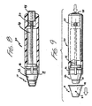
- Fig. 7 is a perspective view of a meter of this invention ejecting a device;
- Fig. 8 is a longitudinal cross section, with certain parts in elevation for clarity, of the meter of Fig. 7 in a first, in-use, position;
- Fig. 9 is a side elevational view, partially in cross section, of the meter of Fig. 7 in a second, ejection, position;
- Fig. 10 is a perspective view of an alternate embodiment of a meter;
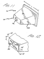
- Fig. 11 is a perspective view of an alternate embodiment of a device of this invention;
- Fig. 12 is a fragmentary perspective view of the distal end of the device of Fig. 11;
- Fig. 13 is a cross-sectional view taken along line 13-13 of Fig. 12;
- Fig. 14 is a cross-sectional view taken along line 14-14 of Fig. 12;
- Fig. 15 is a cross-sectional view of a further embodiment of the distal end of a device of the invention;
- Fig. 16 is a perspective view of another embodiment of a meter and device prior to their being attached;
- Fig. 17 is another embodiment of a meter and device;
- Fig. 18 is a perspective view of the distal end of a further embodiment of the meter and device;
- Fig. 19 is a side view of the distal end of the meter and device of Fig. 18 shown in an assembled position.
-
- The device of the present invention is generally adapted for use in an apparatus for measuring the concentration of analytes, such as alcohol, cholesterol, proteins, ketones, enzymes, phenylalanine, and glucose, in biological fluids such as blood, urine, and saliva. For brevity, we describe the details for using the device in connection with self-monitoring of blood glucose; however, a person of ordinary skill in the art of medical diagnostics would be able to readily adapt the technology for measuring other analytes in other biological fluids.
- Self-monitoring of blood glucose is generally done with meters that operate on one of two principles. The first is the photometric type, which is based on reagent strips that indude a composition that changes color after blood is applied. The color change is a measure of the glucose concentration.
- The second type of blood glucose monitor is electrochemical and operates on the understanding that blood applied to an electrochemical cell can cause an electrical signal - voltage, current, or charge, depending on the type of meter-that can be related to the blood glucose concentration.
- The present invention permits convenient, remote dosing for both photometric and electrochemical systems. For brevity, the description below focuses on a photometric system. Similar devices can be used with an electrochemical system. With either type of system, the present device permits the meter to monitor the complete course of the reaction, from the time the sample is applied until a glucose determination is made. The ability to measure the test start time makes it easier to determine the glucose concentration accurately.
- There are some advantages to using a photometric rather than an electrochemical system to make a glucose determination. One advantage of a photometric system is that measurements can be made at more than one wavelength of light, and corrections can be made for variations in blood hematocrit. The disposable disclosed here provides these advantages of the photometric system, while also permitting minimal meter contamination.
- The disposables used in photometric measurement systems are generally made in the form of a thin rectangular strip. The shape derives from the original so- called "dip and read" test strip configuration. One end serves as a handle, while the chemical reaction with the fluid sample is carried out at the other end.
- These rectangular disposables form the male portion of the interface with the meter. That is, the strip is retained by features on the meter that enclose the disposable. This method of retention invites contamination of the meter with the fluid sample.
- In order to avoid the problems of contamination the present disposable takes the form of a hollow frustum, which provides the female portion of the interface with the meter. That is, the disposable encloses a portion of the meter and serves as a cover to prevent contamination of the meter by the fluid sample.
- Fig. 1 depicts in partial cutaway an embodiment of this invention in which the disposable 10 is a hollow frustum of a cone.
Membrane 12 is attached to thesmaller end 14.Feature 16 provides a surface to whichmembrane 12 is attached withadhesive 18.Optional indentations 20 are spaced around the circumference of the cone to provide a retention mechanism, in conjunction with a groove on a meter. - Fig. 2 is a cross section of the disposable of Fig. 1 taken along the line 2-2. As shown in Fig. 2, the membrane is attached to the outside of the disposable. Alternatively, as shown in Fig. 11, the membrane may be attached to the inside of the disposable.
- Fig. 3 is an exploded perspective view of a photometric meter and a disposable device of the type shown in Fig. 1.
Meter 30 has an elongated configuration with adistal section 32 that is a substantially cylindrically symmetrical frustum, along whose perimeter is optionally agroove 34. Note that the disposable nests on the distal section of the meter in such a way that there is an accurately defined gap G between thedistal end 36 ofmeter 30 and the bottom surface ofmembrane 12. The accurate positioning contributes to measurement precision and reliability. In the cutout can be seen a light source 38 and detector 40, which provide for illuminating a disposable and for detecting light reflected from the disposable, respectively. As discussed below, measuring light reflected from the disposable yields the glucose concentration in the sample applied to the membrane. Although only one source and detector are shown in Fig. 3, multiple sources, optionally having different output spectra, and/or multiple detectors may be used. - Fig. 4 is a perspective view of the way in which a device and meter of Fig. 3 can be used to obtain a sample S from a stuck finger tip. It is quite easy for the user to bring the disposable into contact with the finger, which is a big advantage for users that have impaired vision.
- Fig. 5 is a cross section of part of
distal section 32 ofmeter 30 and disposable 10, which illustrates the way indentations 20 andgroove 34 positively locatemeter 30 within disposable 10, leaving gap G. Note that gap G ensures that blood that penetrates through the membrane does not contaminate the meter. The gap dimension, while not critical, is preferably at least about ½ mm. - An advantage of the device of the invention, when used with a meter of the type shown in Fig. 3, is that the devices can be in a stack, nested conveniently in a
container 42, as shown in Fig. 6. A device can then be secured simply by inserting thedistal section 32 ofmeter 30 intocontainer 42 and engaginggroove 34 andindentations 20. After a test has been completed, a used disposable can be ejected into waste container W, as shown in Fig. 7, provided there is an optional push-button ejection mechanism. - Push-button ejection mechanisms of the type that are widely known and used are suitable for this invention (see e.g.; U.S. Pat. 3,991,617). One such mechanism is depicted in Figs. 8 and 9, which show a push-button mechanism mounted in a meter of the type shown in Fig. 3. The elements of the mechanism include
shaft 44, which joinsejector 46 andpush button 48.Push button 48 works throughshaft 44 to causeejector 46 to disengage disposable 10 from thedistal section 32 ofmeter 30.Spring 50 works to return theejector 46 andpush button 48 to their retracted position. Push-button ejection, by permitting the disposable to be removed without direct contact, helps to avoid contamination. Disposables to be used with push-button ejection mechanisms of the type shown in Figs. 8 and 9 preferably have aflange 19. - Fig. 10 depicts an embodiment of a meter of this invention, which includes a
display 50 for depicting the analyte concentration measured by the meter. The display can be a light-emitting diode (LED) display, a liquid crystal display (LCD), or similar display well known in the art. - Although the above description and Figs. contemplate a disposable having a circular cross section and meter having a distal section having a mating cross section, that geometry is not essential and, in fact, may not even be preferred. A primary consideration in selecting the geometry in a photometric system is the optical design. Generally, reflectometry dictates at least a minimum angular separation (typically 45°) between a detector and specularly reflected light. This, in turn requires at least a minimum vertex angle of the conical disposable. However, it is an advantage to a user to be able to view his/her finger for dosing, and a large vertex angle interferes with that view. Thus, a disposable having a rectangular cross section may be preferred, such as the hollow frustum of a
rectangular pyramid 110 shown in Fig. 11. In that case, the angular separation between detector and specular-reflected light determines only the minimum feasible value of L, the longitudinal dimension of the larger open end. But the disposable could be smaller and provide less interference with a user's view of his/her finger. Furthermore, rectangular membranes can be fabricated from ribbons or sheets at less expense and with less waste of material. Nevertheless, a circular cross section is advantageous when an array of several sources and/or detectors is used in the optical system. - Since contamination is possible if excess sample were to drop from the disposable, it is desirable to accommodate large samples, without dripping. Various designs can serve to retain excess sample. One is shown in Figs. 12, 13, and 14. Fig. 12 depicts the disposable of Fig. 11 with
indentations 124 on the small-end surface of the disposable. As shown in Figs. 13 and 14, the indentations allow capillary flow to fill the resulting gap between the membrane and the top inside surface of the device. An alternative way of forming such gaps is to adhere the membrane to the disposable with thick adhesive, leaving gaps to accommodate the excess sample. Another way to absorb excess sample is to attach anabsorbent pad 126 over the front surface of the membrane, as shown in Fig. 15. - Fig. 16 is an exploded perspective view of a meter and a disposable of the type shown in Fig. 11. The
distal section 132 ofmeter 130 has anoptional groove 134, which is similar to groove 34, for retaining the disposable.Elongated neck 130 facilitates pickup of disposables from theelongated containers 42 shown in Fig. 6.Display 150 depicts the measured analyte concentration. - Fig. 17 depicts an alternative embodiment of a meter adapted for use with the disposable of Fig. 11.
- Fig. 18 depicts the distal portion of yet another embodiment of a disposable 210 and
meter 230.Distal section 232 mates with disposable 210. Note thatslots 234 are an alternative to groove 34 (or 134) for capturing indentations, such as 220, on the disposable. - Fig. 19 is a side view of the embodiment of Fig. 18.
- In the disclosed method, a blood sample is picked up on the outward-facing surface of the membrane. Glucose in the sample interacts with a reagent in the membrane to cause a color change, which changes the reflectance of the inward-facing membrane surface. The light source in the meter illuminates the inward-facing membrane surface and measures the intensity of light reflected from that surface. Using the appropriate computation, the change in reflectance yields the glucose concentration in the sample.
- A variety of combinations of membrane and reagent compositions are known for photometric determinations of blood glucose concentration. A preferred membrane/reagent composition is a polyamide matrix incorporating an oxidase enzyme, a peroxidase, and a dye or dye couple. The oxidase enzyme is preferably glucose oxidase. The peroxidase is preferably horseradish peroxidase. A preferred dye couple is 3-methyl-2 benzothiazolinone hydrazone hydrochloride plus 3,3-dimethylaminobenzoic acid. Details of that membrane/reagent combination and variations on it appear in U.S. Pat. 5,304,468, issued April 19, 1994, to Phillips et al.
- Another preferred membrane/reagent composition is an anisotropic polysulfone membrane (available from Memtec America Corp., Timonium, MD) incorporating glucose oxidase, horseradish peroxidase, and the dye couple [3-methyl-2-benzothiazolinone hydrazone] N-sulfonyl benzenesulfonate monosodium combined with 8-anilino-1-naphthalene sulfonic acid ammonium. Details of that membrane/reagent combination and variations on it appear in U.S. Pat. Appl. Ser. No. 08/302,575, filed September 8,1994.
- It will be understood by those skilled in the art that the foregoing descriptions of embodiments of this invention are illustrative of practicing the present invention but are in no way limiting. Variations of the detail presented herein may be made without departing from the scope of the present invention.
Claims (17)
- A device (10; 110; 210) for use in an apparatus for measuring a concentration of an analyte in a sample of a biological fluid, comprising(a) a hollow frustum, having open ends of unequal size, the smaller open end (14) having an inward-extending surface (16), and(b) a porous membrane (12) for accepting the sample substantially closing the smaller open end (14), the membrane (12) comprisingcharacterised in that the membrane (12) is attached to the inward-extending surface (16) at the smaller open end.(i) a first surface for accepting the sample and(ii) a reagent for reacting with the analyte to cause a colour change at a second surface, opposite to the first surface, resulting in a change iri reflectance at the second surface that can be measured and related to the concentration of the analyte in the sample;
- The device (110) of claim 1, in which the frustum has a rectangular cross section.
- The device (10) of claim 1 in which the frustum has a circular cross section.
- The device (10; 110; 210) of claim 1, claim 2 or claim 3 in which the membrane (12) comprises polyamide.
- The device (10; 110; 210) of claim 1, claim 2 or claim 3 in which the membrane (12) comprises polysulfone.
- The device (10; 110; 210) of any one of the preceding claims, in which the frustum has a plurality of circumferential indentations (20; 120; 220).
- The device (10; 110; 210) of any one of the preceding claims, wherein the second surface of the membrane is attached to the outward-facing surface of the inward-extending surface (16), the device further comprising an absorbent pad (126) over the first surface of the membrane (12).
- The device (10; 110; 210) of any one of claims 1 to 6, in which the membrane (12) is adhered to the inward-extending surface (16) at a plurality of points (18; 124), which are separated by regions where it is not attached.
- The device (10; 110; 210) of any one of claims 1 to 6, in which the membrane (12) is attached to the inward-facing surface of the inward-extending surface (16) on indentations (124) to leave a gap between the surface (16) and the membrane.
- The device (10; 110; 210) of any one of claims 1 to 6 and 8, in which the membrane (12) is attached to the inward-facing surface of the inward-extending surface (16) with thick adhesive to leave a gap between the surface (16) and the membrane.
- The device (10; 110; 210) of any one of the preceding claims in which the larger open end has an outward-extending flange.
- A stack of devices (10; 110; 210) according to any one of the preceding claims, nested in a container (42).
- An apparatus (30) for measuring a concentration of an analyte in a sample of a biological fluid, comprising a device (10; 110; 210) according to any one of the preceding claims for securing to a distal section (32) of the apparatus (30).
- An apparatus (30) according to claim 13, wherein, when a device (10; 110; 210) is secured to the distal section (32), a gap (G) is left between the distal end (36) of the distal section (32) and the second surface of the membrane (12).
- An apparatus (30) according to claim 13 or claim 14, comprising a push button ejection mechanism for ejecting a device (10; 110; 210) off the distal section (32).
- An apparatus (30) according to claim 13, claim 14 or claim 15, comprising a display (50) for depicting the analyte concentration measured by the apparatus (30).
- An apparatus (30) according to any one of claims 13 to 16, wherein the distal section (32) is at the end of an elongated neck (130).
Priority Applications (1)
| Application Number | Priority Date | Filing Date | Title |
|---|---|---|---|
| DK97306039T DK0823635T3 (en) | 1996-08-09 | 1997-08-08 | Reagent test device in the form of a hollow cone or pyramid stub |
Applications Claiming Priority (2)
| Application Number | Priority Date | Filing Date | Title |
|---|---|---|---|
| US694960 | 1996-08-09 | ||
| US08/694,960 US5846486A (en) | 1996-08-09 | 1996-08-09 | Hollow frustum reagent test device |
Publications (3)
| Publication Number | Publication Date |
|---|---|
| EP0823635A2 EP0823635A2 (en) | 1998-02-11 |
| EP0823635A3 EP0823635A3 (en) | 2000-03-15 |
| EP0823635B1 true EP0823635B1 (en) | 2004-12-22 |
Family
ID=24790990
Family Applications (1)
| Application Number | Title | Priority Date | Filing Date |
|---|---|---|---|
| EP97306039A Expired - Lifetime EP0823635B1 (en) | 1996-08-09 | 1997-08-08 | Hollow frustum reagent test device |
Country Status (21)
| Country | Link |
|---|---|
| US (1) | US5846486A (en) |
| EP (1) | EP0823635B1 (en) |
| JP (1) | JPH10127611A (en) |
| KR (1) | KR100562178B1 (en) |
| CN (1) | CN1115562C (en) |
| AR (1) | AR009046A1 (en) |
| AT (1) | ATE285580T1 (en) |
| AU (1) | AU712689B2 (en) |
| BR (1) | BR9704299A (en) |
| CA (1) | CA2212475A1 (en) |
| DE (1) | DE69732003T2 (en) |
| DK (1) | DK0823635T3 (en) |
| ES (1) | ES2235215T3 (en) |
| HK (1) | HK1004422A1 (en) |
| IL (1) | IL121481A (en) |
| MY (1) | MY125477A (en) |
| NO (1) | NO320325B1 (en) |
| PT (1) | PT823635E (en) |
| RU (1) | RU2188425C2 (en) |
| SG (1) | SG91245A1 (en) |
| TW (1) | TW588157B (en) |
Families Citing this family (81)
| Publication number | Priority date | Publication date | Assignee | Title |
|---|---|---|---|---|
| US6391005B1 (en) | 1998-03-30 | 2002-05-21 | Agilent Technologies, Inc. | Apparatus and method for penetration with shaft having a sensor for sensing penetration depth |
| US6554798B1 (en) | 1998-08-18 | 2003-04-29 | Medtronic Minimed, Inc. | External infusion device with remote programming, bolus estimator and/or vibration alarm capabilities |
| US6535753B1 (en) * | 1998-08-20 | 2003-03-18 | Microsense International, Llc | Micro-invasive method for painless detection of analytes in extra-cellular space |
| US6197257B1 (en) * | 1998-08-20 | 2001-03-06 | Microsense Of St. Louis, Llc | Micro sensor device |
| JP3654786B2 (en) * | 1999-02-08 | 2005-06-02 | テルモ株式会社 | Component measurement chip |
| MXPA02004778A (en) * | 1999-11-12 | 2005-09-08 | Pham Tuan | Diagnostic testing kit for collection and testing of fluid samples with user configurable test strips and timer. |
| US6458326B1 (en) | 1999-11-24 | 2002-10-01 | Home Diagnostics, Inc. | Protective test strip platform |
| US8641644B2 (en) | 2000-11-21 | 2014-02-04 | Sanofi-Aventis Deutschland Gmbh | Blood testing apparatus having a rotatable cartridge with multiple lancing elements and testing means |
| US6525330B2 (en) | 2001-02-28 | 2003-02-25 | Home Diagnostics, Inc. | Method of strip insertion detection |
| US6541266B2 (en) | 2001-02-28 | 2003-04-01 | Home Diagnostics, Inc. | Method for determining concentration of an analyte in a test strip |
| US6562625B2 (en) | 2001-02-28 | 2003-05-13 | Home Diagnostics, Inc. | Distinguishing test types through spectral analysis |
| US9226699B2 (en) | 2002-04-19 | 2016-01-05 | Sanofi-Aventis Deutschland Gmbh | Body fluid sampling module with a continuous compression tissue interface surface |
| US7025774B2 (en) | 2001-06-12 | 2006-04-11 | Pelikan Technologies, Inc. | Tissue penetration device |
| US8337419B2 (en) | 2002-04-19 | 2012-12-25 | Sanofi-Aventis Deutschland Gmbh | Tissue penetration device |
| US9795747B2 (en) | 2010-06-02 | 2017-10-24 | Sanofi-Aventis Deutschland Gmbh | Methods and apparatus for lancet actuation |
| WO2002100254A2 (en) | 2001-06-12 | 2002-12-19 | Pelikan Technologies, Inc. | Method and apparatus for lancet launching device integrated onto a blood-sampling cartridge |
| DE60238119D1 (en) | 2001-06-12 | 2010-12-09 | Pelikan Technologies Inc | ELECTRIC ACTUATOR ELEMENT FOR A LANZETTE |
| US7981056B2 (en) | 2002-04-19 | 2011-07-19 | Pelikan Technologies, Inc. | Methods and apparatus for lancet actuation |
| US9427532B2 (en) | 2001-06-12 | 2016-08-30 | Sanofi-Aventis Deutschland Gmbh | Tissue penetration device |
| ES2336081T3 (en) | 2001-06-12 | 2010-04-08 | Pelikan Technologies Inc. | SELF-OPTIMIZATION PUNCTURE DEVICE WITH MEANS OF ADAPTATION TO TEMPORARY VARIATIONS IN CUTANEOUS PROPERTIES. |
| US6939310B2 (en) | 2001-10-10 | 2005-09-06 | Lifescan, Inc. | Devices for physiological fluid sampling and methods of using the same |
| US6723500B2 (en) * | 2001-12-05 | 2004-04-20 | Lifescan, Inc. | Test strips having reaction zones and channels defined by a thermally transferred hydrophobic barrier |
| US6872358B2 (en) | 2002-01-16 | 2005-03-29 | Lifescan, Inc. | Test strip dispenser |
| US20030212379A1 (en) * | 2002-02-26 | 2003-11-13 | Bylund Adam David | Systems and methods for remotely controlling medication infusion and analyte monitoring |
| US7175642B2 (en) | 2002-04-19 | 2007-02-13 | Pelikan Technologies, Inc. | Methods and apparatus for lancet actuation |
| US8702624B2 (en) | 2006-09-29 | 2014-04-22 | Sanofi-Aventis Deutschland Gmbh | Analyte measurement device with a single shot actuator |
| US7547287B2 (en) | 2002-04-19 | 2009-06-16 | Pelikan Technologies, Inc. | Method and apparatus for penetrating tissue |
| US7229458B2 (en) | 2002-04-19 | 2007-06-12 | Pelikan Technologies, Inc. | Method and apparatus for penetrating tissue |
| US9795334B2 (en) | 2002-04-19 | 2017-10-24 | Sanofi-Aventis Deutschland Gmbh | Method and apparatus for penetrating tissue |
| US7901362B2 (en) | 2002-04-19 | 2011-03-08 | Pelikan Technologies, Inc. | Method and apparatus for penetrating tissue |
| US7674232B2 (en) | 2002-04-19 | 2010-03-09 | Pelikan Technologies, Inc. | Method and apparatus for penetrating tissue |
| US7491178B2 (en) | 2002-04-19 | 2009-02-17 | Pelikan Technologies, Inc. | Method and apparatus for penetrating tissue |
| US8784335B2 (en) | 2002-04-19 | 2014-07-22 | Sanofi-Aventis Deutschland Gmbh | Body fluid sampling device with a capacitive sensor |
| US8579831B2 (en) | 2002-04-19 | 2013-11-12 | Sanofi-Aventis Deutschland Gmbh | Method and apparatus for penetrating tissue |
| US9248267B2 (en) | 2002-04-19 | 2016-02-02 | Sanofi-Aventis Deustchland Gmbh | Tissue penetration device |
| US7976476B2 (en) | 2002-04-19 | 2011-07-12 | Pelikan Technologies, Inc. | Device and method for variable speed lancet |
| US7708701B2 (en) | 2002-04-19 | 2010-05-04 | Pelikan Technologies, Inc. | Method and apparatus for a multi-use body fluid sampling device |
| US7892183B2 (en) | 2002-04-19 | 2011-02-22 | Pelikan Technologies, Inc. | Method and apparatus for body fluid sampling and analyte sensing |
| US8372016B2 (en) | 2002-04-19 | 2013-02-12 | Sanofi-Aventis Deutschland Gmbh | Method and apparatus for body fluid sampling and analyte sensing |
| US7909778B2 (en) | 2002-04-19 | 2011-03-22 | Pelikan Technologies, Inc. | Method and apparatus for penetrating tissue |
| US8221334B2 (en) | 2002-04-19 | 2012-07-17 | Sanofi-Aventis Deutschland Gmbh | Method and apparatus for penetrating tissue |
| US9314194B2 (en) | 2002-04-19 | 2016-04-19 | Sanofi-Aventis Deutschland Gmbh | Tissue penetration device |
| US7232451B2 (en) | 2002-04-19 | 2007-06-19 | Pelikan Technologies, Inc. | Method and apparatus for penetrating tissue |
| US7331931B2 (en) | 2002-04-19 | 2008-02-19 | Pelikan Technologies, Inc. | Method and apparatus for penetrating tissue |
| US8267870B2 (en) | 2002-04-19 | 2012-09-18 | Sanofi-Aventis Deutschland Gmbh | Method and apparatus for body fluid sampling with hybrid actuation |
| US7297122B2 (en) | 2002-04-19 | 2007-11-20 | Pelikan Technologies, Inc. | Method and apparatus for penetrating tissue |
| US8360992B2 (en) | 2002-04-19 | 2013-01-29 | Sanofi-Aventis Deutschland Gmbh | Method and apparatus for penetrating tissue |
| US7343188B2 (en) * | 2002-05-09 | 2008-03-11 | Lifescan, Inc. | Devices and methods for accessing and analyzing physiological fluid |
| US20030212344A1 (en) * | 2002-05-09 | 2003-11-13 | Vadim Yuzhakov | Physiological sample collection devices and methods of using the same |
| US20030223906A1 (en) * | 2002-06-03 | 2003-12-04 | Mcallister Devin | Test strip container system |
| ATE396398T1 (en) | 2002-10-29 | 2008-06-15 | Hoffmann La Roche | TEST ELEMENT ANALYSIS SYSTEM |
| US8574895B2 (en) | 2002-12-30 | 2013-11-05 | Sanofi-Aventis Deutschland Gmbh | Method and apparatus using optical techniques to measure analyte levels |
| TW568772B (en) * | 2002-12-31 | 2004-01-01 | Veutron Corp | Apparatus with a combination of a point light source and a single lens |
| ATE476137T1 (en) | 2003-05-30 | 2010-08-15 | Pelikan Technologies Inc | METHOD AND DEVICE FOR INJECTING LIQUID |
| DK1633235T3 (en) | 2003-06-06 | 2014-08-18 | Sanofi Aventis Deutschland | Apparatus for sampling body fluid and detecting analyte |
| WO2006001797A1 (en) | 2004-06-14 | 2006-01-05 | Pelikan Technologies, Inc. | Low pain penetrating |
| WO2005023088A2 (en) * | 2003-09-03 | 2005-03-17 | Facet Technologies, Llc | Endcap for a fluid sampling device |
| EP1671096A4 (en) | 2003-09-29 | 2009-09-16 | Pelikan Technologies Inc | Method and apparatus for an improved sample capture device |
| EP1680014A4 (en) | 2003-10-14 | 2009-01-21 | Pelikan Technologies Inc | Method and apparatus for a variable user interface |
| EP1680175B1 (en) | 2003-11-06 | 2019-06-05 | LifeScan, Inc. | Drug delivery pen with event notification means |
| EP1706026B1 (en) | 2003-12-31 | 2017-03-01 | Sanofi-Aventis Deutschland GmbH | Method and apparatus for improving fluidic flow and sample capture |
| US7822454B1 (en) | 2005-01-03 | 2010-10-26 | Pelikan Technologies, Inc. | Fluid sampling device with improved analyte detecting member configuration |
| US8828203B2 (en) | 2004-05-20 | 2014-09-09 | Sanofi-Aventis Deutschland Gmbh | Printable hydrogels for biosensors |
| US9775553B2 (en) | 2004-06-03 | 2017-10-03 | Sanofi-Aventis Deutschland Gmbh | Method and apparatus for a fluid sampling device |
| WO2005120365A1 (en) | 2004-06-03 | 2005-12-22 | Pelikan Technologies, Inc. | Method and apparatus for a fluid sampling device |
| DE102004057503B4 (en) * | 2004-11-29 | 2013-11-21 | Roche Diagnostics Gmbh | Diagnostic system for determining substance concentrations in liquid samples |
| US8652831B2 (en) | 2004-12-30 | 2014-02-18 | Sanofi-Aventis Deutschland Gmbh | Method and apparatus for analyte measurement test time |
| JP4635140B2 (en) * | 2006-07-31 | 2011-02-16 | アークレイ株式会社 | Lancet-integrated body fluid measuring device and attached body to be used by attaching to this body fluid measuring device |
| WO2009120600A2 (en) | 2008-03-25 | 2009-10-01 | The Curators Of The University Of Missouri | Method and system for non-invasive blood glucose detection utilizing spectral data of one or more components other than glucose |
| WO2009126900A1 (en) | 2008-04-11 | 2009-10-15 | Pelikan Technologies, Inc. | Method and apparatus for analyte detecting device |
| RU2566920C2 (en) | 2008-05-22 | 2015-10-27 | Дзе Кьюрейторз Оф Дзе Юниверсити Оф Миссури | Method and system for non-invasive optic determination of blood glucose with application of data spectral analysis |
| US9375169B2 (en) | 2009-01-30 | 2016-06-28 | Sanofi-Aventis Deutschland Gmbh | Cam drive for managing disposable penetrating member actions with a single motor and motor and control system |
| EP2413784A4 (en) * | 2009-04-01 | 2014-01-22 | Univ Missouri | Optical spectroscopy device for non-invasive blood glucose detection and associated method of use |
| US8574510B2 (en) | 2009-09-30 | 2013-11-05 | Bayer Healthcare Llc | Stackable electrochemical analyte sensors, systems and methods including same |
| JP5668215B2 (en) * | 2009-12-08 | 2015-02-12 | パナソニックヘルスケアホールディングス株式会社 | Biological information measuring device |
| US8965476B2 (en) | 2010-04-16 | 2015-02-24 | Sanofi-Aventis Deutschland Gmbh | Tissue penetration device |
| AT512978B1 (en) * | 2012-06-08 | 2015-10-15 | Hagl Peter Dipl Ing | Cover cap, measuring device with cap and method for producing a cap |
| JP6563892B2 (en) | 2013-03-11 | 2019-08-21 | アセンシア・ディアベティス・ケア・ホールディングス・アーゲー | Strip grabber |
| US9376708B2 (en) | 2013-03-13 | 2016-06-28 | Ascensia Diabetes Care Holdings Ag | Bottled glucose sensor with no handling |
| JP2016518152A (en) * | 2013-03-13 | 2016-06-23 | ボストン サイエンティフィック サイムド,インコーポレイテッドBoston Scientific Scimed,Inc. | Chemochromic medical device |
| EP3172570A4 (en) | 2014-07-25 | 2017-12-27 | Becton, Dickinson and Company | Analyte test strip assays, and test strips and kits for use in practicing the same |
Family Cites Families (17)
| Publication number | Priority date | Publication date | Assignee | Title |
|---|---|---|---|---|
| US3992158A (en) * | 1973-08-16 | 1976-11-16 | Eastman Kodak Company | Integral analytical element |
| FR2287941A1 (en) * | 1974-10-15 | 1976-05-14 | Marteau D Autry Eric | DEVICE FOR EJECTING THE REMOVABLE TIP OF A PIPETTE |
| US4246339A (en) * | 1978-11-01 | 1981-01-20 | Millipore Corporation | Test device |
| US4787398A (en) * | 1985-04-08 | 1988-11-29 | Garid, Inc. | Glucose medical monitoring system |
| US4693834A (en) * | 1986-05-05 | 1987-09-15 | Murex Corporation | Transverse flow diagnostic kit |
| US4774058A (en) * | 1985-09-26 | 1988-09-27 | Mehl Ehrenfried L | Apparatus for, and methods of, operating upon a fluid |
| US4935346A (en) * | 1986-08-13 | 1990-06-19 | Lifescan, Inc. | Minimum procedure system for the determination of analytes |
| US5137691A (en) * | 1987-01-27 | 1992-08-11 | V-Tech, Inc. | Antibody testing system with removable air gap |
| US4874691A (en) * | 1987-10-16 | 1989-10-17 | Quadra Logic Technologies Inc. | Membrane-supported immunoassays |
| US4952373A (en) * | 1989-04-21 | 1990-08-28 | Biotrack, Inc. | Liquid shield for cartridge |
| US5100620A (en) * | 1989-05-15 | 1992-03-31 | Miles, Inc. | Capillary tube/gap reagent format |
| US5306623A (en) * | 1989-08-28 | 1994-04-26 | Lifescan, Inc. | Visual blood glucose concentration test strip |
| JPH06500174A (en) * | 1990-10-30 | 1994-01-06 | ハイポガード(ユーケイ)リミテッド | Collection and display equipment |
| CA2133983C (en) * | 1992-04-27 | 2004-04-06 | Stephen E. Zweig | Test article and method for performing blood coagulation assays |
| CA2105962A1 (en) * | 1992-09-18 | 1994-03-19 | Margaret Patricia Raybuck | Device and method for affinity separation |
| EP0588564B1 (en) * | 1992-09-18 | 1996-11-13 | AMERSHAM INTERNATIONAL plc | Device and method for affinity separation |
| US5563031A (en) * | 1994-09-08 | 1996-10-08 | Lifescan, Inc. | Highly stable oxidative coupling dye for spectrophotometric determination of analytes |
-
1996
- 1996-08-09 US US08/694,960 patent/US5846486A/en not_active Expired - Lifetime
-
1997
- 1997-08-06 IL IL12148197A patent/IL121481A/en not_active IP Right Cessation
- 1997-08-07 AU AU33207/97A patent/AU712689B2/en not_active Expired
- 1997-08-07 CA CA002212475A patent/CA2212475A1/en not_active Abandoned
- 1997-08-07 SG SG9702815A patent/SG91245A1/en unknown
- 1997-08-08 BR BR9704299A patent/BR9704299A/en not_active Application Discontinuation
- 1997-08-08 EP EP97306039A patent/EP0823635B1/en not_active Expired - Lifetime
- 1997-08-08 KR KR1019970038352A patent/KR100562178B1/en not_active IP Right Cessation
- 1997-08-08 DE DE69732003T patent/DE69732003T2/en not_active Expired - Lifetime
- 1997-08-08 NO NO19973660A patent/NO320325B1/en not_active IP Right Cessation
- 1997-08-08 DK DK97306039T patent/DK0823635T3/en active
- 1997-08-08 AT AT97306039T patent/ATE285580T1/en active
- 1997-08-08 JP JP9225610A patent/JPH10127611A/en active Pending
- 1997-08-08 PT PT97306039T patent/PT823635E/en unknown
- 1997-08-08 ES ES97306039T patent/ES2235215T3/en not_active Expired - Lifetime
- 1997-08-08 MY MYPI97003647A patent/MY125477A/en unknown
- 1997-08-08 RU RU97113954/14A patent/RU2188425C2/en active
- 1997-08-09 CN CN97119335A patent/CN1115562C/en not_active Expired - Lifetime
- 1997-08-11 AR ARP970103639A patent/AR009046A1/en unknown
- 1997-08-27 TW TW086111561A patent/TW588157B/en not_active IP Right Cessation
-
1998
- 1998-05-01 HK HK98103749A patent/HK1004422A1/en not_active IP Right Cessation
Also Published As
| Publication number | Publication date |
|---|---|
| AU712689B2 (en) | 1999-11-11 |
| CA2212475A1 (en) | 1998-02-09 |
| US5846486A (en) | 1998-12-08 |
| DK0823635T3 (en) | 2005-04-11 |
| CN1115562C (en) | 2003-07-23 |
| HK1004422A1 (en) | 1998-11-27 |
| DE69732003T2 (en) | 2005-12-15 |
| KR100562178B1 (en) | 2006-08-31 |
| DE69732003D1 (en) | 2005-01-27 |
| EP0823635A2 (en) | 1998-02-11 |
| SG91245A1 (en) | 2002-09-17 |
| EP0823635A3 (en) | 2000-03-15 |
| NO973660L (en) | 1998-02-10 |
| AU3320797A (en) | 1998-02-12 |
| NO320325B1 (en) | 2005-11-21 |
| TW588157B (en) | 2004-05-21 |
| IL121481A0 (en) | 1998-02-08 |
| PT823635E (en) | 2005-03-31 |
| JPH10127611A (en) | 1998-05-19 |
| MY125477A (en) | 2006-08-30 |
| BR9704299A (en) | 1999-01-26 |
| MX9706102A (en) | 1998-05-31 |
| AR009046A1 (en) | 2000-03-08 |
| KR19980018607A (en) | 1998-06-05 |
| NO973660D0 (en) | 1997-08-08 |
| IL121481A (en) | 2000-08-31 |
| RU2188425C2 (en) | 2002-08-27 |
| ES2235215T3 (en) | 2005-07-01 |
| ATE285580T1 (en) | 2005-01-15 |
| CN1178906A (en) | 1998-04-15 |
Similar Documents
| Publication | Publication Date | Title |
|---|---|---|
| EP0823635B1 (en) | Hollow frustum reagent test device | |
| EP0823634B1 (en) | Analyte concentration measurement using a hollow frustum | |
| EP0823636B1 (en) | Remote-dosing analyte concentration meter | |
| US6099802A (en) | Hollow frustum reagent test device | |
| AU688979B2 (en) | Analyte detection strip with orientation index | |
| US20120165626A1 (en) | Devices, methods, and kits for determining analyte concentrations | |
| MXPA97006102A (en) | Hollow troncoconic device for pru reagents | |
| MXPA97006103A (en) | Measurement of analytic concentration through the use of a hu troncoconic device | |
| MXPA97006104A (en) | Concentration meter of analytics by remote |
Legal Events
| Date | Code | Title | Description |
|---|---|---|---|
| PUAI | Public reference made under article 153(3) epc to a published international application that has entered the european phase |
Free format text: ORIGINAL CODE: 0009012 |
|
| AK | Designated contracting states |
Kind code of ref document: A2 Designated state(s): AT BE CH DE DK ES FI FR GB GR IT LI LU NL PT SE |
|
| PUAL | Search report despatched |
Free format text: ORIGINAL CODE: 0009013 |
|
| AK | Designated contracting states |
Kind code of ref document: A3 Designated state(s): AT BE CH DE DK ES FI FR GB GR IE IT LI LU MC NL PT SE |
|
| 17P | Request for examination filed |
Effective date: 20000821 |
|
| AKX | Designation fees paid |
Free format text: AT BE CH DE DK ES FI FR GB GR IT LI LU NL PT SE |
|
| 17Q | First examination report despatched |
Effective date: 20020923 |
|
| GRAP | Despatch of communication of intention to grant a patent |
Free format text: ORIGINAL CODE: EPIDOSNIGR1 |
|
| GRAS | Grant fee paid |
Free format text: ORIGINAL CODE: EPIDOSNIGR3 |
|
| GRAA | (expected) grant |
Free format text: ORIGINAL CODE: 0009210 |
|
| AK | Designated contracting states |
Kind code of ref document: B1 Designated state(s): AT BE CH DE DK ES FI FR GB GR IT LI LU NL PT SE |
|
| REG | Reference to a national code |
Ref country code: GB Ref legal event code: FG4D |
|
| REG | Reference to a national code |
Ref country code: CH Ref legal event code: EP |
|
| REF | Corresponds to: |
Ref document number: 69732003 Country of ref document: DE Date of ref document: 20050127 Kind code of ref document: P |
|
| REG | Reference to a national code |
Ref country code: CH Ref legal event code: NV Representative=s name: E. BLUM & CO. PATENTANWAELTE |
|
| REG | Reference to a national code |
Ref country code: GR Ref legal event code: EP Ref document number: 20050400516 Country of ref document: GR |
|
| REG | Reference to a national code |
Ref country code: PT Ref legal event code: SC4A Free format text: AVAILABILITY OF NATIONAL TRANSLATION Effective date: 20050119 |
|
| REG | Reference to a national code |
Ref country code: DK Ref legal event code: T3 |
|
| REG | Reference to a national code |
Ref country code: SE Ref legal event code: TRGR |
|
| REG | Reference to a national code |
Ref country code: HK Ref legal event code: GR Ref document number: 1004422 Country of ref document: HK |
|
| REG | Reference to a national code |
Ref country code: ES Ref legal event code: FG2A Ref document number: 2235215 Country of ref document: ES Kind code of ref document: T3 |
|
| PLBE | No opposition filed within time limit |
Free format text: ORIGINAL CODE: 0009261 |
|
| STAA | Information on the status of an ep patent application or granted ep patent |
Free format text: STATUS: NO OPPOSITION FILED WITHIN TIME LIMIT |
|
| ET | Fr: translation filed | ||
| 26N | No opposition filed |
Effective date: 20050923 |
|
| REG | Reference to a national code |
Ref country code: CH Ref legal event code: PFA Owner name: LIFESCAN, INC. Free format text: LIFESCAN, INC.#1000 GIBRALTAR DRIVE#MILPITAS, CALIFORNIA 95035-6312 (US) -TRANSFER TO- LIFESCAN, INC.#1000 GIBRALTAR DRIVE#MILPITAS, CALIFORNIA 95035-6312 (US) |
|
| REG | Reference to a national code |
Ref country code: FR Ref legal event code: PLFP Year of fee payment: 20 |
|
| PGFP | Annual fee paid to national office [announced via postgrant information from national office to epo] |
Ref country code: LU Payment date: 20160801 Year of fee payment: 20 Ref country code: NL Payment date: 20160810 Year of fee payment: 20 |
|
| PGFP | Annual fee paid to national office [announced via postgrant information from national office to epo] |
Ref country code: CH Payment date: 20160812 Year of fee payment: 20 Ref country code: IT Payment date: 20160822 Year of fee payment: 20 Ref country code: GB Payment date: 20160803 Year of fee payment: 20 Ref country code: FI Payment date: 20160809 Year of fee payment: 20 Ref country code: DK Payment date: 20160810 Year of fee payment: 20 Ref country code: DE Payment date: 20160802 Year of fee payment: 20 |
|
| PGFP | Annual fee paid to national office [announced via postgrant information from national office to epo] |
Ref country code: FR Payment date: 20160712 Year of fee payment: 20 Ref country code: AT Payment date: 20160725 Year of fee payment: 20 Ref country code: SE Payment date: 20160811 Year of fee payment: 20 Ref country code: PT Payment date: 20160804 Year of fee payment: 20 Ref country code: GR Payment date: 20160722 Year of fee payment: 20 |
|
| PGFP | Annual fee paid to national office [announced via postgrant information from national office to epo] |
Ref country code: ES Payment date: 20160712 Year of fee payment: 20 Ref country code: BE Payment date: 20160713 Year of fee payment: 20 |
|
| REG | Reference to a national code |
Ref country code: DE Ref legal event code: R071 Ref document number: 69732003 Country of ref document: DE |
|
| REG | Reference to a national code |
Ref country code: NL Ref legal event code: MK Effective date: 20170807 |
|
| REG | Reference to a national code |
Ref country code: DK Ref legal event code: EUP Effective date: 20170808 |
|
| REG | Reference to a national code |
Ref country code: CH Ref legal event code: PL |
|
| REG | Reference to a national code |
Ref country code: GB Ref legal event code: PE20 Expiry date: 20170807 |
|
| REG | Reference to a national code |
Ref country code: AT Ref legal event code: MK07 Ref document number: 285580 Country of ref document: AT Kind code of ref document: T Effective date: 20170808 |
|
| REG | Reference to a national code |
Ref country code: SE Ref legal event code: EUG |
|
| REG | Reference to a national code |
Ref country code: BE Ref legal event code: MK Effective date: 20170808 |
|
| REG | Reference to a national code |
Ref country code: ES Ref legal event code: FD2A Effective date: 20171124 |
|
| PG25 | Lapsed in a contracting state [announced via postgrant information from national office to epo] |
Ref country code: PT Free format text: LAPSE BECAUSE OF EXPIRATION OF PROTECTION Effective date: 20170817 Ref country code: GB Free format text: LAPSE BECAUSE OF EXPIRATION OF PROTECTION Effective date: 20170807 |
|
| PG25 | Lapsed in a contracting state [announced via postgrant information from national office to epo] |
Ref country code: ES Free format text: LAPSE BECAUSE OF EXPIRATION OF PROTECTION Effective date: 20170809 |