EP0822084A2 - An ink jet recording head, an ink jet head cartridge, and an ink jet recording apparatus - Google Patents
An ink jet recording head, an ink jet head cartridge, and an ink jet recording apparatus Download PDFInfo
- Publication number
- EP0822084A2 EP0822084A2 EP97113153A EP97113153A EP0822084A2 EP 0822084 A2 EP0822084 A2 EP 0822084A2 EP 97113153 A EP97113153 A EP 97113153A EP 97113153 A EP97113153 A EP 97113153A EP 0822084 A2 EP0822084 A2 EP 0822084A2
- Authority
- EP
- European Patent Office
- Prior art keywords
- ink
- ink jet
- tanks
- recording
- jet recording
- Prior art date
- Legal status (The legal status is an assumption and is not a legal conclusion. Google has not performed a legal analysis and makes no representation as to the accuracy of the status listed.)
- Granted
Links
Images


Classifications
-
- B—PERFORMING OPERATIONS; TRANSPORTING
- B41—PRINTING; LINING MACHINES; TYPEWRITERS; STAMPS
- B41J—TYPEWRITERS; SELECTIVE PRINTING MECHANISMS, i.e. MECHANISMS PRINTING OTHERWISE THAN FROM A FORME; CORRECTION OF TYPOGRAPHICAL ERRORS
- B41J2/00—Typewriters or selective printing mechanisms characterised by the printing or marking process for which they are designed
- B41J2/005—Typewriters or selective printing mechanisms characterised by the printing or marking process for which they are designed characterised by bringing liquid or particles selectively into contact with a printing material
- B41J2/01—Ink jet
- B41J2/17—Ink jet characterised by ink handling
-
- B—PERFORMING OPERATIONS; TRANSPORTING
- B44—DECORATIVE ARTS
- B44C—PRODUCING DECORATIVE EFFECTS; MOSAICS; TARSIA WORK; PAPERHANGING
- B44C1/00—Processes, not specifically provided for elsewhere, for producing decorative surface effects
- B44C1/16—Processes, not specifically provided for elsewhere, for producing decorative surface effects for applying transfer pictures or the like
- B44C1/165—Processes, not specifically provided for elsewhere, for producing decorative surface effects for applying transfer pictures or the like for decalcomanias; sheet material therefor
- B44C1/17—Dry transfer
- B44C1/1712—Decalcomanias applied under heat and pressure, e.g. provided with a heat activable adhesive
-
- B—PERFORMING OPERATIONS; TRANSPORTING
- B41—PRINTING; LINING MACHINES; TYPEWRITERS; STAMPS
- B41J—TYPEWRITERS; SELECTIVE PRINTING MECHANISMS, i.e. MECHANISMS PRINTING OTHERWISE THAN FROM A FORME; CORRECTION OF TYPOGRAPHICAL ERRORS
- B41J2/00—Typewriters or selective printing mechanisms characterised by the printing or marking process for which they are designed
- B41J2/005—Typewriters or selective printing mechanisms characterised by the printing or marking process for which they are designed characterised by bringing liquid or particles selectively into contact with a printing material
- B41J2/01—Ink jet
- B41J2/17—Ink jet characterised by ink handling
- B41J2/175—Ink supply systems ; Circuit parts therefor
- B41J2/17503—Ink cartridges
- B41J2/17513—Inner structure
-
- B—PERFORMING OPERATIONS; TRANSPORTING
- B41—PRINTING; LINING MACHINES; TYPEWRITERS; STAMPS
- B41J—TYPEWRITERS; SELECTIVE PRINTING MECHANISMS, i.e. MECHANISMS PRINTING OTHERWISE THAN FROM A FORME; CORRECTION OF TYPOGRAPHICAL ERRORS
- B41J2/00—Typewriters or selective printing mechanisms characterised by the printing or marking process for which they are designed
- B41J2/005—Typewriters or selective printing mechanisms characterised by the printing or marking process for which they are designed characterised by bringing liquid or particles selectively into contact with a printing material
- B41J2/01—Ink jet
- B41J2/17—Ink jet characterised by ink handling
- B41J2/175—Ink supply systems ; Circuit parts therefor
- B41J2/17503—Ink cartridges
- B41J2/1752—Mounting within the printer
-
- B—PERFORMING OPERATIONS; TRANSPORTING
- B41—PRINTING; LINING MACHINES; TYPEWRITERS; STAMPS
- B41J—TYPEWRITERS; SELECTIVE PRINTING MECHANISMS, i.e. MECHANISMS PRINTING OTHERWISE THAN FROM A FORME; CORRECTION OF TYPOGRAPHICAL ERRORS
- B41J2/00—Typewriters or selective printing mechanisms characterised by the printing or marking process for which they are designed
- B41J2/005—Typewriters or selective printing mechanisms characterised by the printing or marking process for which they are designed characterised by bringing liquid or particles selectively into contact with a printing material
- B41J2/01—Ink jet
- B41J2/17—Ink jet characterised by ink handling
- B41J2/175—Ink supply systems ; Circuit parts therefor
- B41J2/17503—Ink cartridges
- B41J2/17526—Electrical contacts to the cartridge
Definitions
- the present invention relates to the ink jet recording head of an ink jet recording apparatus. More particularly, the invention relates to an ink jet recording head that scans across a recording medium, such as a paper sheet.
- An ink jet recording apparatus is the recording apparatus of the so-called non-impact type recording apparatus, which is capable of recording at high speeds on various kinds of recording media. This apparatus is characterized in that it makes almost no noises at the time of recording. Because of this feature, the ink jet recording apparatus is widely adopted for an apparatus to serve as a printer, a word processor, a facsimile, a copying machine, and others that operate recording system.
- the ink jet recording As a typical method applicable to the ink jet recording, there is the one that uses electrothermal transducing devices to perform recording on a recording sheet by discharging fine droplets from fine discharge ports.
- This method is generally structured by an ink jet recording head that forms droplets, and a supply system that supplies ink to this head.
- the ink jet recording head that uses electrothermal transducing devices is provided with the electrothermal transducing devices in the pressurized chambers, and thermal energy is given to recording liquid by applying electric pulses, which serve as recording signals, to the electrothermal transducing devices.
- the pressure of bubbles is utilized for discharging recording droplets at the time of foaming of recording liquid (film boiling) generated by change of phases of the recording liquid.
- an ink jet recording head there is the one having the system that allows its ink tanks to be separated or does not allow them to be separated from the head.
- Figs. 10A and 10B are views which show the outer appearances of the conventional ink jet recording head of a system that allows its ink tanks to be separated from it.
- Fig. 10A is a cross-sectional view showing the principal part on the front thereof.
- Fig. 10B is a side view of such recording head.
- the recording unit 1 comprises a recording device substrate (not shown) fixed to a base plate 3, and an ink supply member 4 connected with the recording device substrate, among some others.
- the wiring substrate 5 that supplies recording signals to the recording device substrate is adhesively bonded to the base plate 3.
- a holder member 25 is provided with an ink supply path 7 for supplying ink from the ink tank when it is connected with the ink supply member 4 of the recording unit 1.
- a filter 9 is provided for the joint portion between the ink supply path 7 and the ink tank to remove dust particles, bubbles, and the like in ink.
- the recording unit 1 and the holder member 25 are fixed by thermally caulking the caulking pin of the holder member 25 to couple it with the base plate of the recording unit 1.
- the ink supply member 4 of the recording unit 1 and the ink supply path 7 of the holder member 25 are connected by the application of sealing rubber 26 or a bonding agent (silicone sealant, for instance).
- the present invention is designed with a view to solving the problems described above.
- the objectives of the invention are to simplify the structure of junction between the recording unit and holder member, thus providing an ink jet recording head at lower costs with higher reliability.
- the ink jet recording head of the present invention is structured by coupling the recording unit, which is provided with all the functions of discharging ink, and the holder member, which is provided only with the function of holding and fixing ink tanks.
- the recording unit is provided with all the functions of discharging ink, making it unnecessary to connect ink supply paths or the like. Consequently, there is no need for any provision of sealing members.
- the inspection of the recording heads can be made only in accordance with the recording unit. The number of parts is made smaller for an easier manufacture. Therefore, not only the reliability of heads become higher, but also, the recording heads are provided at lower costs.
- Fig. 1 is a perspective view which shows an ink jet recording head in accordance with a first embodiment of the present invention.
- Fig. 2 is an exploded view which shows the ink jet recording head represented in Fig. 1.
- Figs. 3A, 3B, 3C and 3D are views which illustrate the ink jet recording head represented in Fig. 1, observed in the directions indicated by arrows A to D in Fig. 1, respectively.
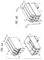
- Figs. 4A and 4B are perspective views which illustrate the states where an ink tank is mounted on the ink jet recording head of the first embodiment.
- Fig. 5 is a cross-sectional view which shows the ink jet recording head, taken along line 5 - 5 in Fig. 4B.
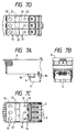
- Figs. 6A, 6B, 6C and 6D are views which illustrate the outer appearance of an ink jet recording head in accordance with a second embodiment of the present invention.
- Figs. 7A, 7B, 7C and 7D are views which illustrate the outer appearance of another ink jet recording head in accordance with a second embodiment of the present invention.
- Figs. 8A and 8B are perspective views which illustrate an ink jet recording head in accordance with a third embodiment of the present invention.
- Fig. 9 is a cross-sectional view which shows the ink jet recording head of the third embodiment.
- Figs. 10A and 10B are cross-sectional views which illustrate the principal part of the conventional ink jet recording head.
- Figs. 11A and 11B are perspective views which illustrate an ink tank in accordance with a first embodiment of the present invention
- Fig. 11C is a cross-sectional view of this ink tank.
- Figs. 12A, 12B, 12C and 12D are cross-sectional views which illustrate the state where the ink tanks represented in Figs. 11A, 11B and 11C are being installed.
- Fig. 13 is a cross-sectional view which shows an ink tank and an ink jet head cartridge.
- Fig. 14 is a perspective view which shows an ink tank in accordance with a second embodiment of the present invention.
- Fig. 15 is a perspective view which shows an ink tank in accordance with a third embodiment of the present invention.
- Fig. 16 is a perspective view which shows a color ink jet recording apparatus.
- Figs. 17A and 17B are perspective views which illustrate an ink jet head cartridge.
- Figs. 18A and 18B are perspective views which illustrate an ink tank.
- Fig. 18C is a cross-sectional view of this ink tank.
- Figs. 19A, 19B and 19C are cross-sectional views which illustrate the state where an ink tank is being mounted on an ink jet head cartridge.
- Figs. 20A and 20B are cross-sectional views which illustrate the state where an ink tank is being mounted on an ink jet head cartridge.
- the ink jet recording head of the present invention that enables its ink tank to be separated from or coupled with the head comprises a recording device substrate having a plurality of recording devices arranged thereon for discharging ink; a wiring substrate to apply electrical recording signals to the recording device substrate from the outside; an ink supply member that holds and fixes the recording device substrate and wiring substrate, and supplies ink to the recording device substrate; and a filter member to remove dust particles and the like in ink.
- This ink jet recording head is characterized in that it is structured by the recording unit having all the functions of discharging ink therefor, which is coupled with the holder member having only the function of holding and fixing ink tanks.
- the recording unit and the holder member are fixed by means of screws or by the application of bonding agent.
- the recording unit is provided with a part of fixing unit that holds and fixes each of the ink tanks.
- the holder member is provided with apertures for positioning ink tanks, apertures for holding and fixing ink tanks, apertures for reading the ink remains in the ink tanks optically, and apertures for reading the ink remains visually by eyesight.
- Fig. 1 is a perspective view showing an ink jet recording head in accordance with a first embodiment of the present invention.
- Fig. 2 is an exploded view of the ink jet recording head shown in Fig. 1.
- Figs. 3A to 3D are views of the head, observed in the directions indicated by arrows A to D in Fig. 1.
- Fig. 4A is a perspective view showing the state before the ink tank is mounted on the ink jet head.
- Fig. 4B is also a perspective view showing the state after the ink tank is mounted on the head.
- Fig. 5 is a cross-sectional view taken along line 5 - 5 in Fig. 4B.
- a reference numeral 2 designates a recording device substrate having a plurality of recording devices being arranged thereon; 5, a wiring substrate having signals lines provided therefor to give recording signals to the recording device substrate 2; and 4, an ink supply member to supply ink to the recording device substrate 2.
- Both the recording device substrate 2 and the wiring substrate 5 are held and fixed to the ink supply member 4.
- the ink supply opening 8 of the ink supply member 4 is provided with a filter 9 to remove and trap dust particles and bubbles in ink.
- the recording unit 1 is formed. Ink is supplied from the ink supply opening 8 of the recording unit 1. Recording signals are given to the wiring substrate 5 from outside. Thus, ink jet recording is performed. In other words, all the functions of discharging ink are incorporated in this recording unit 1.
- a reference numeral 6 designates the holder member having the function of holding and fixing ink tanks.
- the holder member 6 is provided only with ink tank fixing holes 13a and 13b and partition walls 11 between each of the ink tanks, serving as the fixing unit that holds and fixes the ink tanks, and ink tank positioning holes (apertures) 12, apertures 21 for detecting the ink remains in the ink tanks optically as shown in Figs. 3A to 3D, and apertures 22 for reading the ink remains in the ink tanks visually by eyesight (see Figs. 4A and 4B).
- the holder member 6 has only the functions of coupling it with the recording unit 1 in order to hold and fix the ink tanks, and the function of detecting ink remains.
- ink tanks 14 are inserted into the holder member 6, the ink tank fixing ribs 18 and 19 arranged on the sides, and the ink tank positioning knobs 20 arranged on the bottom of the ink tanks engage with the ink tank fixing holes 13a and 13b, and the ink tank positioning holes 12 arranged on the holder member 6, respectively, thus fixing the ink tanks 14.
- the surface of the ink supply opening 17 of the ink tanks 14 and the surface of the filter 9 arranged for the ink supply opening 8 of the recording unit 1 are positioned precisely.
- the first embodiment of the present invention is characterized in that the ink jet head is structured by coupling together the recording unit 1 which is provided with all the functions of discharging ink, and the holder member 6 which is provided only with the function of holding and fixing ink tanks.
- Figs. 6A to 6D and Figs. 7A to 7D are views showing the outer appearance of an ink jet recording head in accordance with a second embodiment of the present invention.
- each of the reference marks is the same as each of those applied to the first embodiment shown in Figs. 3A to 3D. Therefore, the description thereof will be omitted.
- the recording unit 1 and the holder member 6 are coupled and fixed by means of screws 15 (see Figs. 6A to 6D) or by the application of bonding agent 16 (see Figs. 7A to 7D).
- the ink jet recording head should be prevented from being broken even when the recording head falls off onto a floor or the like by mistake. Particularly, it is necessary to prevent the recording unit 1 and the holder member 6 from being separated in such a case.
- the engagement between the recording unit 1 and the holder member 6 is arranged by means of screws 15 and/or by the application of bonding agent 16 so as to make the mechanical strength of the coupling portion stronger for them.
- Figs. 8A and 8B show an ink jet recording head in accordance with a third embodiment of the present invention
- Fig. 8A is a perspective view showing the ink jet recording head
- Fig. 8B is an exploded perspective view thereof.
- Fig. 9 is a cross-sectional view showing the state where the ink tank is mounted on the ink jet recording head of the third embodiment.
- each of the reference marks is the same as each of those applied to the first embodiment shown in Figs. 1, 2 and 5. Therefore, the description thereof will be omitted.
- the recording unit 1 is provided with ink tank fixing holes 13 to hold and fix ink tanks 14.
- the positioning precision between the surface of the ink supply opening 17 of the ink tanks 14 and the surface of the filter 9 provided for the ink supply opening 8 of the recording unit 1 is most important with respect to the ink supply.
- all the portions that regulate the position of the ink tanks 14 are provided only for the holder member 6 as in the first embodiment; it tends to lower the positioning precision between the surface of the ink supply opening 17 and the surface of the filter 9 of the ink supply opening 8 due to the accumulated errors of the coupling play between the holder member 6 and the recording unit 1 and the dimensional errors of the holder member 6 and the recording unit 1.
- the ink tank fixing holes 13a are arranged for the recording unit 1 to hold and fix the ink tanks 14 by allowing them to engage with the ink tank fixing ribs 18 arranged on the side nearer to the surface of the ink supply opening 17 of the ink tank 14. In this way, it is made possible to improve the positioning precision between the surface of the ink supply opening 17 of the ink tanks 14 and the surface of the filter 9 of the ink supply opening 8 of the recording unit 1.
- the ink tanks described in accordance with the first embodiment are fixed when the ink tank fixing ribs 18, 19, and 20 engage with the holder.
- the description will be made of the state of the ink tank being mounted on the holder.
- the ink tank of the present embodiment is arranged so as not to damage the joint portion of the head cartridge when the ink tank is mounted even if the ink supply opening thereof is configured to protrude outward.
- the ink jet head cartridge houses the ink jet head that discharges ink, and also, through the holding mechanism, the head cartridge detachably houses the ink tanks that retain ink to be supplied to the ink jet head.
- Each of the ink tanks comprises the ink supply opening arranged on the bottom thereof; the first nail for fixing the ink tank, which is arranged on the bottom side of the first side; and the second nail arranged to be shiftable by means of a movable lever provided for the second side that faces the first side. Then, the structure is formed so that the third nail is provided above the first nail on the first side in order to regulate the mounting direction.
- Figs. 11A and 11B are perspective views showing the ink tank in accordance with the present embodiment.
- Fig. 11C is a cross-sectional view showing the state where the ink tank is mounted.
- Figs. 12A, 12B, 12C and 12D are cross-sectional views which illustrate the state where the ink tanks represented in Figs. 11A, 11B and 11C are being installed.
- the ink tank 11 is provided with the ink supply opening 211 in a shape that protrudes downward.
- the first nail 18 is arranged as the ink tank fixing rib that fixes the ink tank to the tank holder.
- the third nail is arranged above the first nail in order to regulate the mounting direction of the ink tank.
- the second nail 19 serving as an ink tank fixing rib, which can turn out from the fixing position by means of the movable lever 30.
- the tank holder 6 of the ink jet head cartridge having the ink tanks 14 mounted thereon there are arranged the first hole 13a for fixing the ink tank, which engages with the first nail 18, and the second hole 13b for fixing the ink tank, which engages with the second nail 19.
- the upper part of the side of the tank holder 6 where the first hole is arranged is inclined outward. The ink tank is guided by means of this inclined portion, and then, the upper end 43 of this inclined portion is formed to be in contact with the third nail of the tank which is inserted slantly.
- the ink tank 14 When the ink tank 14 is put in the holder 6 of the ink jet head cartridge in the normal posture, the ink tank is guided by means of the inclined portion so that the first nail 18 engages with the first hole 13a. In this state, the ink tank is pressed in from above. Then, the movable member 30 is caused to bend inward so that the second nail 19 is inserted into the second hole 13b, and the ink tank 14 is mounted on and fixed to the ink jet head 1. At this juncture, the third nail 33 is retained in the inner side of the tank holder which is inclined outward.
- the third nail 33 abuts upon the upper end 43 of the holder before the outer circumference of the ink supply opening 211 is in contact with the joint portion 204 of the head cartridge. Therefore, the outer circumference of the ink supply opening is prevented from abutting upon the joint portion.
- the ink tank rotates with the third nail as a fulcrum, and when the side of the ink tank is in contact with the inclined portion of the holder, the third nail is caused to part from the upper end of the holder.
- the first nail 18 engages with the first hole 13a.
- the ink tanks are coupled with the ink jet head.
- Fig. 13 is a cross-sectional view which shows the ink tank and the ink jet head cartridge.
- m the distance from the upper end of the first nail 18 to the lower end of the third nail (in the height direction) as m, and the distance from the upper end of the first hole 13a of the first hole of the tank holder to the upper end 43 of the side of the holder as n, it is preferable to set the relationship between them as follows: n ⁇ m ⁇ n + 0.5 mm
- the tolerance of this play of 0.5 mm is ⁇ 0.2 mm. Normally, the ink tank cannot be mounted accurately if the play is more or less than this tolerance.
- the first nail and the third nail are arranged almost on the central portion of the side of the ink tank.
- the nails may be prepared in plural numbers as shown in Fig. 14. This mode is particularly suitable for a tank having a larger capacity.
- Fig. 16 is a perspective view which shows an ink jet head recording apparatus generally in use.
- Figs. 17A and 17B are perspective views which shows an ink jet head cartridge to be mounted in a carriage.
- the carriage 101 travels on a lead screw 104 and a guide shaft 105 in parallel with them by means of the lead screw 104 interlocked with a carriage motor (not shown).
- an ink jet head 102 is fixed as shown in Figs. 17A and 17B.
- a black ink tank 111, a yellow ink tank 112, a magenta ink tank 113, and a cyan ink tank 114 are detachably mounted along the tank holder 103 to supply ink.
- Fig. 17A shows the ink jet head cartridge before the ink tank are mounted in the tank holder 103 and Fig. 17B shows the ink jet head cartridge after the ink tanks are mounted in the tank holder 103.
- Ink discharged from the ink jet head 102 is shot onto a recording medium serving as a recording sheet 106 for the present embodiment, which faces the ink jet head 102 for the formation of images. While being carried for printing by means of a sheet feed roller 107, a sheet exhaust roller 108, and a sheet pressure plate 109, which are interlocked with a sheet exhaust motor (not shown), the recording sheet 106 is exhausted.
- An ink jet recording head capable of separating or coupling ink tanks from or with the head comprises a recording device substrate having a plurality of recording devices thereon for discharging ink, a wiring device for giving electrical recording signals to the recording device substrate, an ink supply member for supplying ink to the recording device substrate, and a filter member for removing dust particles or the like in ink.
- This recording unit is provided with all the functions of discharging ink, and coupled with a holder member having only the function of holding and fixing ink tanks. With the structure thus arranged, it becomes unnecessary to connect ink supply paths as in the conventional art, hence eliminating the provision of sealing members. The number of parts is made smaller, while making it possible to carry out inspection of heads only in accordance with the recording units, which significantly contributes to simplifying manufacture and providing highly reliable heads at lower costs.
Abstract
Description
Claims (15)
- An ink jet recording head capable of separating or coupling ink tanks from or with said head, comprising:a recording device substrate having a plurality of recording devices thereon for discharging ink;a wiring device for giving electrical recording signals to said recording device substrate;an ink supply member for supplying ink to said recording device substrate; anda filter member for removing dust particles or the like in ink, anda recording unit provided with all the functions of discharging ink being coupled with a holder member having only the function of holding and fixing ink tanks.
- An ink jet recording head according to Claim 1, wherein said recording unit and said holder member are fixed by means of screws or by the application of bonding agent.
- An ink jet recording head according to Claim 1, wherein a part of fixing portion for holding and fixing said ink tanks is provided for said recording unit.
- An ink jet recording head according to Claim 2, wherein a part of fixing portion for holding and fixing said ink tanks is provided for said recording unit.
- An ink jet recording head according to Claim 1, wherein said holder member comprises openings for positioning ink tanks, openings for optically reading ink remains in ink tanks, and opening for reading ink remains visually by eyesight.
- An ink jet recording head according to Claim 2, wherein said holder member comprises openings for positioning ink tanks, openings for optically reading ink remains in ink tanks, and opening for reading ink remains visually by eyesight.
- An ink jet recording head according to Claim 3, wherein said holder member comprises openings for positioning ink tanks, openings for optically reading ink remains in ink tanks, and opening for reading ink remains visually by eyesight.
- An ink jet recording head according to Claim 4, wherein said holder member comprises openings for positioning ink tanks, openings for optically reading ink remains in ink tanks, and opening for reading ink remains visually by eyesight.
- An ink jet recording head according to Claim 1, wherein said recording unit is attachable and detachable to and from said holder member.
- An ink jet head cartridge provided with an ink jet head, and ink tanks retaining ink to be supplied to said ink jet head and being attachable and detachable to and from said ink jet head through a holder mechanism,each of said ink tanks having an ink supply opening on the bottom thereof, a first nail for fixing ink tank arranged on the bottom of a first side, a second nail for fixing ink tank being movable by means of a movable lever arranged on a second side facing said first side, and a third nail arranged above said first nail on said first side for regulating the mounting direction.
- An ink jet head cartridge according to Claim 10, wherein said holder mechanism is provided with an inclined portion on the part thereof facing said first side of said ink tank.
- An ink jet head cartridge according to Claim 11, wherein given the distance from the upper end of the first nail of said ink tank to the lower end of said third nail as m, and the distance from the upper end of the first hole engaging with said first nail of said holder mechanism to the upper end of said inclined portion as n, the relationship between them is:
- An ink tank detachably mountable on an ink jet head cartridge provided with an ink jet head, and a holder mechanism to detachably couple therewith ink tanks retaining ink to be supplied to said ink jet head, comprising:an ink supply opening on the bottom thereof;a first nail for fixing ink tank arranged on the bottom of a first side;a second nail for fixing ink tank being movable by means of a movable lever arranged on a second side facing said first side; anda third nail arranged above said first nail on said first side for regulating the mounting direction.
- An ink jet recording apparatus comprising:an ink jet recording head according to Claim 1; anda driving mechanism for moving said ink jet recording head.
- An ink jet recording apparatus comprising:an ink jet head cartridge according to either one of Claim 6 to Claim 8; anda driving mechanism for moving said ink jet recording head.
Applications Claiming Priority (6)
| Application Number | Priority Date | Filing Date | Title |
|---|---|---|---|
| JP202246/96 | 1996-07-31 | ||
| JP8202246A JPH1044465A (en) | 1996-07-31 | 1996-07-31 | Ink jet recording head |
| JP20224696 | 1996-07-31 | ||
| JP202250/96 | 1996-07-31 | ||
| JP20225096 | 1996-07-31 | ||
| JP20225096A JP3530684B2 (en) | 1996-07-31 | 1996-07-31 | Ink tank |
Publications (3)
| Publication Number | Publication Date |
|---|---|
| EP0822084A2 true EP0822084A2 (en) | 1998-02-04 |
| EP0822084A3 EP0822084A3 (en) | 1998-12-16 |
| EP0822084B1 EP0822084B1 (en) | 2003-05-28 |
Family
ID=26513265
Family Applications (1)
| Application Number | Title | Priority Date | Filing Date |
|---|---|---|---|
| EP97113153A Expired - Lifetime EP0822084B1 (en) | 1996-07-31 | 1997-07-30 | An ink jet recording head, an ink jet head cartridge, and an ink jet recording apparatus |
Country Status (10)
| Country | Link |
|---|---|
| US (1) | US6464338B1 (en) |
| EP (1) | EP0822084B1 (en) |
| KR (1) | KR100221508B1 (en) |
| CN (1) | CN1087229C (en) |
| AT (1) | ATE241473T1 (en) |
| AU (1) | AU745397B2 (en) |
| CA (1) | CA2212266C (en) |
| DE (1) | DE69722324T2 (en) |
| ES (1) | ES2197272T3 (en) |
| TW (1) | TW369486B (en) |
Cited By (13)
| Publication number | Priority date | Publication date | Assignee | Title |
|---|---|---|---|---|
| EP1000749A2 (en) * | 1998-10-27 | 2000-05-17 | Canon Kabushiki Kaisha | Ink tank, ink jet head cartridge, and ink jet recording apparatus |
| EP1122076A1 (en) * | 2000-01-31 | 2001-08-08 | Hewlett-Packard Company, A Delaware Corporation | Replaceable ink container having a seperately attachable latch |
| US6350025B1 (en) * | 1998-09-03 | 2002-02-26 | Canon Kabushiki Kaisha | Ink tank with improved handling, tank holder for installation of such ink tank, ink jet cartridge, and ink jet recording apparatus |
| EP1188567A2 (en) * | 2000-09-06 | 2002-03-20 | Canon Kabushiki Kaisha | Electric contacts on ink jet recording head |
| US6502917B1 (en) | 1998-05-18 | 2003-01-07 | Seiko Epson Corporation | Ink-jet printing apparatus and ink cartridge therefor |
| US6634738B1 (en) | 1999-10-12 | 2003-10-21 | Seiko Epson Corporation | Ink cartridge for ink-jet printing apparatus |
| WO2003103973A1 (en) * | 2002-06-11 | 2003-12-18 | セイコーエプソン株式会社 | Ink cartridge |
| AU2002301858B2 (en) * | 1998-10-27 | 2004-11-11 | Canon Kabushiki Kaisha | Ink Tank, Ink Jet Head Cartridge, and Ink Jet Recording Apparatus |
| US6863376B2 (en) | 2001-04-03 | 2005-03-08 | Seiko Epson Corporation | Ink cartridge and ink-jet recording apparatus |
| US6913351B2 (en) * | 2002-02-15 | 2005-07-05 | Canon Kabushiki Kaisha | Liquid jet recording head and recording apparatus |
| US6955422B2 (en) | 2001-04-03 | 2005-10-18 | Seiko Epson Corporation | Ink cartridge |
| US6979079B2 (en) | 2002-11-26 | 2005-12-27 | Seiko Epson Corporation | Ink cartridge and recording apparatus |
| US7008053B2 (en) | 2002-11-26 | 2006-03-07 | Seiko Epson Corporation | Ink cartridge and recording apparatus |
Families Citing this family (11)
| Publication number | Priority date | Publication date | Assignee | Title |
|---|---|---|---|---|
| TWI259149B (en) * | 2002-09-30 | 2006-08-01 | Canon Kk | Ink container and recording apparatus |
| US7134747B2 (en) * | 2002-09-30 | 2006-11-14 | Canon Kabushiki Kaisha | Ink container, recording head and recording device using same |
| MXPA04012681A (en) * | 2003-12-26 | 2005-07-01 | Canon Kk | Liquid container and liquid supplying system. |
| KR100612321B1 (en) * | 2004-07-12 | 2006-08-16 | 삼성전자주식회사 | Ink cartridge and the ink-jet printer thereof |
| US7625072B2 (en) * | 2004-07-22 | 2009-12-01 | Canon Kabushiki Kaisha | Ink jet recording head and recording apparatus |
| JP4290154B2 (en) * | 2004-12-08 | 2009-07-01 | キヤノン株式会社 | Liquid discharge recording head and ink jet recording apparatus |
| CN100334266C (en) * | 2005-12-20 | 2007-08-29 | 东华大学 | Mfg. of fiber for textile by environment protection biological-chemical method |
| JP4882733B2 (en) * | 2006-03-30 | 2012-02-22 | ブラザー工業株式会社 | ink cartridge |
| JP2007276344A (en) | 2006-04-10 | 2007-10-25 | Fuji Xerox Co Ltd | Droplet discharge head, its manufacturing method, and droplet discharge apparatus |
| US7810917B2 (en) * | 2006-12-21 | 2010-10-12 | Eastman Kodak Company | Printing device fluid reservoir with alignment features |
| JP6976735B2 (en) | 2017-06-15 | 2021-12-08 | キヤノン株式会社 | How to install the liquid discharge head, liquid discharge device and liquid discharge head |
Citations (7)
| Publication number | Priority date | Publication date | Assignee | Title |
|---|---|---|---|---|
| JPH0631930A (en) * | 1992-07-14 | 1994-02-08 | Fuji Xerox Co Ltd | Inkjet recording apparatus |
| EP0639462A2 (en) * | 1993-08-19 | 1995-02-22 | Canon Kabushiki Kaisha | Ink tank cartridge and ink-jet apparatus in which the ink tank cartridge is installed |
| EP0655336A1 (en) * | 1993-11-29 | 1995-05-31 | Canon Kabushiki Kaisha | Improved ink container, installing-removing method therefore, and apparatus usable with the same |
| EP0698497A2 (en) * | 1994-08-24 | 1996-02-28 | Canon Kabushiki Kaisha | Ink container for ink jet printer, holder for the container carriage for the holder and ink jet printer |
| EP0699532A2 (en) * | 1994-08-31 | 1996-03-06 | Canon Kabushiki Kaisha | Ink jet refilling method and apparatus for ink container |
| EP0706888A2 (en) * | 1994-10-14 | 1996-04-17 | Canon Kabushiki Kaisha | Ink jet recording apparatus having residual quantity detection unit and residual quantity detection method therefor |
| EP0765757A2 (en) * | 1995-09-28 | 1997-04-02 | Fuji Xerox Co., Ltd. | Ink jet recording unit |
Family Cites Families (4)
| Publication number | Priority date | Publication date | Assignee | Title |
|---|---|---|---|---|
| JP2817657B2 (en) * | 1994-08-23 | 1998-10-30 | 富士ゼロックス株式会社 | Ink supply device and recording device |
| JPS631930A (en) * | 1986-06-20 | 1988-01-06 | Iseki & Co Ltd | Grain weighing apparatus |
| JP3217610B2 (en) * | 1993-09-03 | 2001-10-09 | キヤノン株式会社 | Ink jet recording device and information processing system |
| DE9405723U1 (en) * | 1994-04-06 | 1994-06-01 | Pelikan Produktions Ag Egg | Ink cartridge for a printhead of an ink jet printer |
-
1997
- 1997-07-28 US US08/901,107 patent/US6464338B1/en not_active Expired - Lifetime
- 1997-07-29 TW TW086110812A patent/TW369486B/en not_active IP Right Cessation
- 1997-07-30 EP EP97113153A patent/EP0822084B1/en not_active Expired - Lifetime
- 1997-07-30 CA CA002212266A patent/CA2212266C/en not_active Expired - Fee Related
- 1997-07-30 AT AT97113153T patent/ATE241473T1/en active
- 1997-07-30 DE DE69722324T patent/DE69722324T2/en not_active Expired - Lifetime
- 1997-07-30 AU AU32380/97A patent/AU745397B2/en not_active Ceased
- 1997-07-30 ES ES97113153T patent/ES2197272T3/en not_active Expired - Lifetime
- 1997-07-31 CN CN97117457A patent/CN1087229C/en not_active Expired - Fee Related
- 1997-07-31 KR KR1019970036342A patent/KR100221508B1/en not_active IP Right Cessation
Patent Citations (7)
| Publication number | Priority date | Publication date | Assignee | Title |
|---|---|---|---|---|
| JPH0631930A (en) * | 1992-07-14 | 1994-02-08 | Fuji Xerox Co Ltd | Inkjet recording apparatus |
| EP0639462A2 (en) * | 1993-08-19 | 1995-02-22 | Canon Kabushiki Kaisha | Ink tank cartridge and ink-jet apparatus in which the ink tank cartridge is installed |
| EP0655336A1 (en) * | 1993-11-29 | 1995-05-31 | Canon Kabushiki Kaisha | Improved ink container, installing-removing method therefore, and apparatus usable with the same |
| EP0698497A2 (en) * | 1994-08-24 | 1996-02-28 | Canon Kabushiki Kaisha | Ink container for ink jet printer, holder for the container carriage for the holder and ink jet printer |
| EP0699532A2 (en) * | 1994-08-31 | 1996-03-06 | Canon Kabushiki Kaisha | Ink jet refilling method and apparatus for ink container |
| EP0706888A2 (en) * | 1994-10-14 | 1996-04-17 | Canon Kabushiki Kaisha | Ink jet recording apparatus having residual quantity detection unit and residual quantity detection method therefor |
| EP0765757A2 (en) * | 1995-09-28 | 1997-04-02 | Fuji Xerox Co., Ltd. | Ink jet recording unit |
Non-Patent Citations (1)
| Title |
|---|
| PATENT ABSTRACTS OF JAPAN vol. 018, no. 243 (M-1602), 10 May 1994 & JP 06 031930 A (FUJI XEROX CO LTD), 8 February 1994 * |
Cited By (40)
| Publication number | Priority date | Publication date | Assignee | Title |
|---|---|---|---|---|
| DE19964216B4 (en) * | 1998-05-18 | 2007-12-13 | Seiko Epson Corp. | Ink-jet recorder and ink cartridge |
| US7954934B2 (en) | 1998-05-18 | 2011-06-07 | Seiko Epson Corporation | Ink-jet printing apparatus and ink cartridge therefor |
| US7669969B2 (en) | 1998-05-18 | 2010-03-02 | Seiko Epson Corporation | Ink-jet printing apparatus and ink cartridge therefor |
| US6550902B2 (en) | 1998-05-18 | 2003-04-22 | Seiko Epson Corporation | Ink-jet printing apparatus and ink cartridge therefor |
| US6502917B1 (en) | 1998-05-18 | 2003-01-07 | Seiko Epson Corporation | Ink-jet printing apparatus and ink cartridge therefor |
| US6350025B1 (en) * | 1998-09-03 | 2002-02-26 | Canon Kabushiki Kaisha | Ink tank with improved handling, tank holder for installation of such ink tank, ink jet cartridge, and ink jet recording apparatus |
| US6390601B1 (en) | 1998-10-27 | 2002-05-21 | Canon Kabushiki Kaisha | Ink tank, ink jet head cartridge, and ink jet recording apparatus |
| AU2002301858B2 (en) * | 1998-10-27 | 2004-11-11 | Canon Kabushiki Kaisha | Ink Tank, Ink Jet Head Cartridge, and Ink Jet Recording Apparatus |
| EP1000749A2 (en) * | 1998-10-27 | 2000-05-17 | Canon Kabushiki Kaisha | Ink tank, ink jet head cartridge, and ink jet recording apparatus |
| AU756458B2 (en) * | 1998-10-27 | 2003-01-16 | Canon Kabushiki Kaisha | Ink tank, ink jet head cartridge, and ink jet recording apparatus |
| EP1000749A3 (en) * | 1998-10-27 | 2000-07-26 | Canon Kabushiki Kaisha | Ink tank, ink jet head cartridge, and ink jet recording apparatus |
| CN1113754C (en) * | 1998-10-27 | 2003-07-09 | 佳能株式会社 | Ink pot, ink jet head assembly and ink jet recording device |
| AU2002301857B2 (en) * | 1998-10-27 | 2004-11-11 | Canon Kabushiki Kaisha | Ink Tank, Ink Jet Head Cartridge, and Ink Jet Recording Apparatus |
| US6634738B1 (en) | 1999-10-12 | 2003-10-21 | Seiko Epson Corporation | Ink cartridge for ink-jet printing apparatus |
| US6908184B2 (en) | 1999-10-12 | 2005-06-21 | Seiko Epson Corporation | Ink cartridge for ink-jet printing apparatus |
| EP1122076A1 (en) * | 2000-01-31 | 2001-08-08 | Hewlett-Packard Company, A Delaware Corporation | Replaceable ink container having a seperately attachable latch |
| US6431697B1 (en) | 2000-01-31 | 2002-08-13 | Hewlett-Packard Company | Replaceable ink container having a separately attachable latch and method for assembling the container |
| US6749287B2 (en) | 2000-09-06 | 2004-06-15 | Canon Kabushiki Kaisha | Ink jet recording head and ink jet recording apparatus |
| EP1188567A3 (en) * | 2000-09-06 | 2002-09-11 | Canon Kabushiki Kaisha | Electric contacts on ink jet recording head |
| EP1188567A2 (en) * | 2000-09-06 | 2002-03-20 | Canon Kabushiki Kaisha | Electric contacts on ink jet recording head |
| US7566112B2 (en) | 2001-04-03 | 2009-07-28 | Seiko Epson Corporation | Ink cartridge and ink-jet recording apparatus |
| US6955422B2 (en) | 2001-04-03 | 2005-10-18 | Seiko Epson Corporation | Ink cartridge |
| US6863376B2 (en) | 2001-04-03 | 2005-03-08 | Seiko Epson Corporation | Ink cartridge and ink-jet recording apparatus |
| US7018030B2 (en) | 2001-04-03 | 2006-03-28 | Seiko Epson Corporation | Ink cartridge and ink-jet recording apparatus |
| US7178902B2 (en) | 2001-04-03 | 2007-02-20 | Seiko Epson Corporation | Ink cartridge and ink-jet recording apparatus |
| US6913351B2 (en) * | 2002-02-15 | 2005-07-05 | Canon Kabushiki Kaisha | Liquid jet recording head and recording apparatus |
| CN100333914C (en) * | 2002-06-11 | 2007-08-29 | 精工爱普生株式会社 | Ink cartridge |
| WO2003103973A1 (en) * | 2002-06-11 | 2003-12-18 | セイコーエプソン株式会社 | Ink cartridge |
| EP1512536A4 (en) * | 2002-06-11 | 2007-08-22 | Seiko Epson Corp | Ink cartridge |
| US7240990B2 (en) | 2002-06-11 | 2007-07-10 | Seiko Epson Corporation | Ink cartridge |
| EP1512536A1 (en) * | 2002-06-11 | 2005-03-09 | Seiko Epson Corporation | Ink cartridge |
| DE10341100B4 (en) * | 2002-11-26 | 2009-05-20 | Seiko Epson Corp. | ink cartridge |
| EP2050573A2 (en) | 2002-11-26 | 2009-04-22 | Seiko Epson Corporation | Ink cartridge |
| US7244018B2 (en) | 2002-11-26 | 2007-07-17 | Seiko Epson Corporation | Ink cartridge having retaining structure and memory |
| US6979079B2 (en) | 2002-11-26 | 2005-12-27 | Seiko Epson Corporation | Ink cartridge and recording apparatus |
| DE10362128B4 (en) * | 2002-11-26 | 2008-09-11 | Seiko Epson Corp. | Ink cartridge and recording device |
| US7669993B2 (en) | 2002-11-26 | 2010-03-02 | Seiko Epson Corporation | Ink cartridge and recording apparatus |
| EP2165834A1 (en) | 2002-11-26 | 2010-03-24 | Seiko Epson Corporation | Ink cartridge |
| US7686441B2 (en) | 2002-11-26 | 2010-03-30 | Seiko Epson Corporation | Ink cartridge and recording apparatus |
| US7008053B2 (en) | 2002-11-26 | 2006-03-07 | Seiko Epson Corporation | Ink cartridge and recording apparatus |
Also Published As
| Publication number | Publication date |
|---|---|
| KR100221508B1 (en) | 1999-09-15 |
| AU745397B2 (en) | 2002-03-21 |
| CN1087229C (en) | 2002-07-10 |
| ATE241473T1 (en) | 2003-06-15 |
| CN1174127A (en) | 1998-02-25 |
| AU3238097A (en) | 1998-02-05 |
| CA2212266A1 (en) | 1998-01-31 |
| MX9705776A (en) | 1998-08-30 |
| ES2197272T3 (en) | 2004-01-01 |
| CA2212266C (en) | 2005-05-24 |
| KR980008578A (en) | 1998-04-30 |
| EP0822084A3 (en) | 1998-12-16 |
| US6464338B1 (en) | 2002-10-15 |
| DE69722324T2 (en) | 2004-02-12 |
| DE69722324D1 (en) | 2003-07-03 |
| TW369486B (en) | 1999-09-11 |
| EP0822084B1 (en) | 2003-05-28 |
Similar Documents
| Publication | Publication Date | Title |
|---|---|---|
| EP0822084B1 (en) | An ink jet recording head, an ink jet head cartridge, and an ink jet recording apparatus | |
| EP0546544B1 (en) | Ink jet recording apparatus | |
| KR100357680B1 (en) | Ink tank, ink supply system, ink jet head cartridge, and ink jet recording apparatus | |
| EP2527154B3 (en) | Combined ink family keying for an ink cartridge | |
| EP0829363B1 (en) | Ink container, ink container holder for removably holding ink container, and ink container cap | |
| US6824243B2 (en) | Liquid jet print head and liquid jet printing apparatus | |
| EP0418817B1 (en) | Ink jet recording head and ink jet recording apparatus using same | |
| US6851795B2 (en) | Cartridge with opposed electrical and ink connection portions, and carriage and ink jet recording apparatus for same | |
| EP1484182A1 (en) | Ink container and ink container holder | |
| JP4027111B2 (en) | Liquid jet recording head | |
| JP2003237107A (en) | Liquid jet recording head and liquid jet recorder | |
| JPH0239945A (en) | Ink cartridge | |
| JP2001063084A (en) | Ink tank holding member and ink-jet cartridge comprising the holding member | |
| JPH1044451A (en) | Ink jet head cartridge and ink jet recorder | |
| AU2003200319B2 (en) | An Ink Jet Recording Head, an Ink Jet Head Cartridge, and an Ink Jet Recording Apparatus | |
| US6913351B2 (en) | Liquid jet recording head and recording apparatus | |
| MXPA97005776A (en) | Ink jet registration head, ink jet head cartridge, and it jet registration apparatus | |
| JPH1044465A (en) | Ink jet recording head | |
| EP3505353B1 (en) | System including liquid cartridge and cartridge receiving portion | |
| JP2006168071A (en) | Ink tank, recording head cartridge and method for attaching ink tank | |
| JPH10235889A (en) | Ink jet cartridge | |
| JP2005186292A (en) | Inkjet head |
Legal Events
| Date | Code | Title | Description |
|---|---|---|---|
| PUAI | Public reference made under article 153(3) epc to a published international application that has entered the european phase |
Free format text: ORIGINAL CODE: 0009012 |
|
| AK | Designated contracting states |
Kind code of ref document: A2 Designated state(s): AT CH DE ES FR GB IT LI NL |
|
| AX | Request for extension of the european patent |
Free format text: AL;LT;LV;RO;SI |
|
| PUAL | Search report despatched |
Free format text: ORIGINAL CODE: 0009013 |
|
| AK | Designated contracting states |
Kind code of ref document: A3 Designated state(s): AT BE CH DE DK ES FI FR GB GR IE IT LI LU MC NL PT SE |
|
| AX | Request for extension of the european patent |
Free format text: AL;LT;LV;RO;SI |
|
| 17P | Request for examination filed |
Effective date: 19990503 |
|
| AKX | Designation fees paid |
Free format text: AT CH DE ES FR GB IT LI NL |
|
| 17Q | First examination report despatched |
Effective date: 20010612 |
|
| GRAH | Despatch of communication of intention to grant a patent |
Free format text: ORIGINAL CODE: EPIDOS IGRA |
|
| GRAH | Despatch of communication of intention to grant a patent |
Free format text: ORIGINAL CODE: EPIDOS IGRA |
|
| GRAA | (expected) grant |
Free format text: ORIGINAL CODE: 0009210 |
|
| AK | Designated contracting states |
Designated state(s): AT CH DE ES FR GB IT LI NL |
|
| REG | Reference to a national code |
Ref country code: GB Ref legal event code: FG4D |
|
| REG | Reference to a national code |
Ref country code: CH Ref legal event code: EP |
|
| REF | Corresponds to: |
Ref document number: 69722324 Country of ref document: DE Date of ref document: 20030703 Kind code of ref document: P |
|
| REG | Reference to a national code |
Ref country code: CH Ref legal event code: NV Representative=s name: BOVARD AG PATENTANWAELTE |
|
| REG | Reference to a national code |
Ref country code: ES Ref legal event code: FG2A Ref document number: 2197272 Country of ref document: ES Kind code of ref document: T3 |
|
| ET | Fr: translation filed | ||
| PLBE | No opposition filed within time limit |
Free format text: ORIGINAL CODE: 0009261 |
|
| STAA | Information on the status of an ep patent application or granted ep patent |
Free format text: STATUS: NO OPPOSITION FILED WITHIN TIME LIMIT |
|
| 26N | No opposition filed |
Effective date: 20040302 |
|
| REG | Reference to a national code |
Ref country code: CH Ref legal event code: PFA Owner name: CANON KABUSHIKI KAISHA Free format text: CANON KABUSHIKI KAISHA#30-2, 3-CHOME, SHIMOMARUKO, OHTA-KU#TOKYO (JP) -TRANSFER TO- CANON KABUSHIKI KAISHA#30-2, 3-CHOME, SHIMOMARUKO, OHTA-KU#TOKYO (JP) |
|
| REG | Reference to a national code |
Ref country code: FR Ref legal event code: PLFP Year of fee payment: 19 |
|
| PGFP | Annual fee paid to national office [announced via postgrant information from national office to epo] |
Ref country code: NL Payment date: 20150608 Year of fee payment: 19 |
|
| PGFP | Annual fee paid to national office [announced via postgrant information from national office to epo] |
Ref country code: CH Payment date: 20150729 Year of fee payment: 19 Ref country code: GB Payment date: 20150727 Year of fee payment: 19 Ref country code: ES Payment date: 20150714 Year of fee payment: 19 Ref country code: DE Payment date: 20150731 Year of fee payment: 19 |
|
| PGFP | Annual fee paid to national office [announced via postgrant information from national office to epo] |
Ref country code: FR Payment date: 20150729 Year of fee payment: 19 Ref country code: AT Payment date: 20150717 Year of fee payment: 19 |
|
| PGFP | Annual fee paid to national office [announced via postgrant information from national office to epo] |
Ref country code: IT Payment date: 20150708 Year of fee payment: 19 |
|
| REG | Reference to a national code |
Ref country code: DE Ref legal event code: R119 Ref document number: 69722324 Country of ref document: DE |
|
| REG | Reference to a national code |
Ref country code: CH Ref legal event code: PL |
|
| REG | Reference to a national code |
Ref country code: NL Ref legal event code: MM Effective date: 20160801 |
|
| REG | Reference to a national code |
Ref country code: AT Ref legal event code: MM01 Ref document number: 241473 Country of ref document: AT Kind code of ref document: T Effective date: 20160730 |
|
| GBPC | Gb: european patent ceased through non-payment of renewal fee |
Effective date: 20160730 |
|
| PG25 | Lapsed in a contracting state [announced via postgrant information from national office to epo] |
Ref country code: CH Free format text: LAPSE BECAUSE OF NON-PAYMENT OF DUE FEES Effective date: 20160731 Ref country code: LI Free format text: LAPSE BECAUSE OF NON-PAYMENT OF DUE FEES Effective date: 20160731 Ref country code: FR Free format text: LAPSE BECAUSE OF NON-PAYMENT OF DUE FEES Effective date: 20160801 Ref country code: NL Free format text: LAPSE BECAUSE OF NON-PAYMENT OF DUE FEES Effective date: 20160801 Ref country code: DE Free format text: LAPSE BECAUSE OF NON-PAYMENT OF DUE FEES Effective date: 20170201 |
|
| REG | Reference to a national code |
Ref country code: FR Ref legal event code: ST Effective date: 20170331 |
|
| PG25 | Lapsed in a contracting state [announced via postgrant information from national office to epo] |
Ref country code: GB Free format text: LAPSE BECAUSE OF NON-PAYMENT OF DUE FEES Effective date: 20160730 Ref country code: AT Free format text: LAPSE BECAUSE OF NON-PAYMENT OF DUE FEES Effective date: 20160730 |
|
| PG25 | Lapsed in a contracting state [announced via postgrant information from national office to epo] |
Ref country code: IT Free format text: LAPSE BECAUSE OF NON-PAYMENT OF DUE FEES Effective date: 20160730 |
|
| REG | Reference to a national code |
Ref country code: ES Ref legal event code: FD2A Effective date: 20180507 |
|
| PG25 | Lapsed in a contracting state [announced via postgrant information from national office to epo] |
Ref country code: ES Free format text: LAPSE BECAUSE OF NON-PAYMENT OF DUE FEES Effective date: 20160731 |