EP0822077B1 - Liquid-ejection head and method of manufacturing the same - Google Patents
Liquid-ejection head and method of manufacturing the same Download PDFInfo
- Publication number
- EP0822077B1 EP0822077B1 EP97113006A EP97113006A EP0822077B1 EP 0822077 B1 EP0822077 B1 EP 0822077B1 EP 97113006 A EP97113006 A EP 97113006A EP 97113006 A EP97113006 A EP 97113006A EP 0822077 B1 EP0822077 B1 EP 0822077B1
- Authority
- EP
- European Patent Office
- Prior art keywords
- liquid
- depression region
- ejection orifices
- array
- printing
- Prior art date
- Legal status (The legal status is an assumption and is not a legal conclusion. Google has not performed a legal analysis and makes no representation as to the accuracy of the status listed.)
- Expired - Lifetime
Links
- 238000004519 manufacturing process Methods 0.000 title claims description 12
- 238000007639 printing Methods 0.000 claims description 93
- 239000011347 resin Substances 0.000 claims description 44
- 229920005989 resin Polymers 0.000 claims description 44
- 238000007789 sealing Methods 0.000 claims description 33
- 238000000034 method Methods 0.000 claims description 31
- 239000007788 liquid Substances 0.000 claims description 27
- 239000000463 material Substances 0.000 claims description 15
- 239000004744 fabric Substances 0.000 claims description 7
- 239000004033 plastic Substances 0.000 claims description 7
- 230000033001 locomotion Effects 0.000 claims description 6
- 238000012545 processing Methods 0.000 claims description 6
- 229910010293 ceramic material Inorganic materials 0.000 claims description 3
- 239000007769 metal material Substances 0.000 claims description 3
- 238000009835 boiling Methods 0.000 claims 2
- 239000000976 ink Substances 0.000 description 42
- 238000007641 inkjet printing Methods 0.000 description 18
- 230000008569 process Effects 0.000 description 12
- 239000000758 substrate Substances 0.000 description 9
- XUIMIQQOPSSXEZ-UHFFFAOYSA-N Silicon Chemical compound [Si] XUIMIQQOPSSXEZ-UHFFFAOYSA-N 0.000 description 8
- 229910052710 silicon Inorganic materials 0.000 description 8
- 239000010703 silicon Substances 0.000 description 8
- 238000011282 treatment Methods 0.000 description 8
- 239000000470 constituent Substances 0.000 description 7
- 239000010410 layer Substances 0.000 description 7
- 238000000206 photolithography Methods 0.000 description 7
- 238000002203 pretreatment Methods 0.000 description 6
- 239000004020 conductor Substances 0.000 description 5
- 229910052751 metal Inorganic materials 0.000 description 5
- 239000002184 metal Substances 0.000 description 5
- 230000015572 biosynthetic process Effects 0.000 description 4
- 239000003086 colorant Substances 0.000 description 4
- 239000010408 film Substances 0.000 description 4
- 239000010985 leather Substances 0.000 description 4
- 238000000059 patterning Methods 0.000 description 4
- 239000011241 protective layer Substances 0.000 description 4
- KWYUFKZDYYNOTN-UHFFFAOYSA-M Potassium hydroxide Chemical compound [OH-].[K+] KWYUFKZDYYNOTN-UHFFFAOYSA-M 0.000 description 3
- XSQUKJJJFZCRTK-UHFFFAOYSA-N Urea Chemical compound NC(N)=O XSQUKJJJFZCRTK-UHFFFAOYSA-N 0.000 description 3
- 230000005587 bubbling Effects 0.000 description 3
- 239000000919 ceramic Substances 0.000 description 3
- 239000010409 thin film Substances 0.000 description 3
- 239000002023 wood Substances 0.000 description 3
- RYGMFSIKBFXOCR-UHFFFAOYSA-N Copper Chemical compound [Cu] RYGMFSIKBFXOCR-UHFFFAOYSA-N 0.000 description 2
- 229910052782 aluminium Inorganic materials 0.000 description 2
- XAGFODPZIPBFFR-UHFFFAOYSA-N aluminium Chemical compound [Al] XAGFODPZIPBFFR-UHFFFAOYSA-N 0.000 description 2
- 230000000903 blocking effect Effects 0.000 description 2
- 238000005266 casting Methods 0.000 description 2
- 238000004891 communication Methods 0.000 description 2
- 229910052802 copper Inorganic materials 0.000 description 2
- 239000010949 copper Substances 0.000 description 2
- 238000010586 diagram Methods 0.000 description 2
- 239000000428 dust Substances 0.000 description 2
- 230000005611 electricity Effects 0.000 description 2
- 238000005516 engineering process Methods 0.000 description 2
- 238000005530 etching Methods 0.000 description 2
- 239000000835 fiber Substances 0.000 description 2
- 239000011521 glass Substances 0.000 description 2
- 230000006872 improvement Effects 0.000 description 2
- 238000000465 moulding Methods 0.000 description 2
- 230000009467 reduction Effects 0.000 description 2
- 230000003068 static effect Effects 0.000 description 2
- 239000004753 textile Substances 0.000 description 2
- UMGDCJDMYOKAJW-UHFFFAOYSA-N thiourea Chemical compound NC(N)=S UMGDCJDMYOKAJW-UHFFFAOYSA-N 0.000 description 2
- 238000011144 upstream manufacturing Methods 0.000 description 2
- XLYOFNOQVPJJNP-UHFFFAOYSA-N water Substances O XLYOFNOQVPJJNP-UHFFFAOYSA-N 0.000 description 2
- 235000017166 Bambusa arundinacea Nutrition 0.000 description 1
- 235000017491 Bambusa tulda Nutrition 0.000 description 1
- 241001330002 Bambuseae Species 0.000 description 1
- 241000283690 Bos taurus Species 0.000 description 1
- CBENFWSGALASAD-UHFFFAOYSA-N Ozone Chemical compound [O-][O+]=O CBENFWSGALASAD-UHFFFAOYSA-N 0.000 description 1
- 235000015334 Phyllostachys viridis Nutrition 0.000 description 1
- 230000002159 abnormal effect Effects 0.000 description 1
- 230000009471 action Effects 0.000 description 1
- 239000011425 bamboo Substances 0.000 description 1
- 239000011230 binding agent Substances 0.000 description 1
- 238000005422 blasting Methods 0.000 description 1
- 230000000740 bleeding effect Effects 0.000 description 1
- 239000004202 carbamide Substances 0.000 description 1
- 230000015556 catabolic process Effects 0.000 description 1
- 239000011248 coating agent Substances 0.000 description 1
- 238000000576 coating method Methods 0.000 description 1
- 238000010276 construction Methods 0.000 description 1
- 238000005520 cutting process Methods 0.000 description 1
- 230000006735 deficit Effects 0.000 description 1
- 238000006731 degradation reaction Methods 0.000 description 1
- 230000001419 dependent effect Effects 0.000 description 1
- 230000000994 depressogenic effect Effects 0.000 description 1
- 238000013461 design Methods 0.000 description 1
- 238000011161 development Methods 0.000 description 1
- 230000018109 developmental process Effects 0.000 description 1
- 230000000694 effects Effects 0.000 description 1
- 238000009429 electrical wiring Methods 0.000 description 1
- PCHJSUWPFVWCPO-UHFFFAOYSA-N gold Chemical compound [Au] PCHJSUWPFVWCPO-UHFFFAOYSA-N 0.000 description 1
- 239000010931 gold Substances 0.000 description 1
- 229910052737 gold Inorganic materials 0.000 description 1
- 238000010438 heat treatment Methods 0.000 description 1
- 238000009413 insulation Methods 0.000 description 1
- 239000002649 leather substitute Substances 0.000 description 1
- 238000012423 maintenance Methods 0.000 description 1
- 230000003287 optical effect Effects 0.000 description 1
- 230000002093 peripheral effect Effects 0.000 description 1
- 238000007747 plating Methods 0.000 description 1
- 239000011120 plywood Substances 0.000 description 1
- 229920001721 polyimide Polymers 0.000 description 1
- 229920000642 polymer Polymers 0.000 description 1
- 238000003825 pressing Methods 0.000 description 1
- 230000002265 prevention Effects 0.000 description 1
- 230000001737 promoting effect Effects 0.000 description 1
- 238000011084 recovery Methods 0.000 description 1
- 150000003839 salts Chemical class 0.000 description 1
- 238000005549 size reduction Methods 0.000 description 1
- 239000002195 soluble material Substances 0.000 description 1
- 230000000007 visual effect Effects 0.000 description 1
- 238000005406 washing Methods 0.000 description 1
Images


Classifications
-
- B—PERFORMING OPERATIONS; TRANSPORTING
- B41—PRINTING; LINING MACHINES; TYPEWRITERS; STAMPS
- B41J—TYPEWRITERS; SELECTIVE PRINTING MECHANISMS, i.e. MECHANISMS PRINTING OTHERWISE THAN FROM A FORME; CORRECTION OF TYPOGRAPHICAL ERRORS
- B41J2/00—Typewriters or selective printing mechanisms characterised by the printing or marking process for which they are designed
- B41J2/005—Typewriters or selective printing mechanisms characterised by the printing or marking process for which they are designed characterised by bringing liquid or particles selectively into contact with a printing material
- B41J2/01—Ink jet
- B41J2/135—Nozzles
- B41J2/14—Structure thereof only for on-demand ink jet heads
- B41J2/14016—Structure of bubble jet print heads
- B41J2/14024—Assembling head parts
-
- B—PERFORMING OPERATIONS; TRANSPORTING
- B41—PRINTING; LINING MACHINES; TYPEWRITERS; STAMPS
- B41J—TYPEWRITERS; SELECTIVE PRINTING MECHANISMS, i.e. MECHANISMS PRINTING OTHERWISE THAN FROM A FORME; CORRECTION OF TYPOGRAPHICAL ERRORS
- B41J2/00—Typewriters or selective printing mechanisms characterised by the printing or marking process for which they are designed
- B41J2/005—Typewriters or selective printing mechanisms characterised by the printing or marking process for which they are designed characterised by bringing liquid or particles selectively into contact with a printing material
- B41J2/01—Ink jet
- B41J2/135—Nozzles
- B41J2/14—Structure thereof only for on-demand ink jet heads
- B41J2/14016—Structure of bubble jet print heads
- B41J2/14072—Electrical connections, e.g. details on electrodes, connecting the chip to the outside...
-
- B—PERFORMING OPERATIONS; TRANSPORTING
- B41—PRINTING; LINING MACHINES; TYPEWRITERS; STAMPS
- B41J—TYPEWRITERS; SELECTIVE PRINTING MECHANISMS, i.e. MECHANISMS PRINTING OTHERWISE THAN FROM A FORME; CORRECTION OF TYPOGRAPHICAL ERRORS
- B41J2/00—Typewriters or selective printing mechanisms characterised by the printing or marking process for which they are designed
- B41J2/005—Typewriters or selective printing mechanisms characterised by the printing or marking process for which they are designed characterised by bringing liquid or particles selectively into contact with a printing material
- B41J2/01—Ink jet
- B41J2/135—Nozzles
- B41J2/16—Production of nozzles
- B41J2/1601—Production of bubble jet print heads
- B41J2/1603—Production of bubble jet print heads of the front shooter type
-
- B—PERFORMING OPERATIONS; TRANSPORTING
- B41—PRINTING; LINING MACHINES; TYPEWRITERS; STAMPS
- B41J—TYPEWRITERS; SELECTIVE PRINTING MECHANISMS, i.e. MECHANISMS PRINTING OTHERWISE THAN FROM A FORME; CORRECTION OF TYPOGRAPHICAL ERRORS
- B41J2/00—Typewriters or selective printing mechanisms characterised by the printing or marking process for which they are designed
- B41J2/005—Typewriters or selective printing mechanisms characterised by the printing or marking process for which they are designed characterised by bringing liquid or particles selectively into contact with a printing material
- B41J2/01—Ink jet
- B41J2/135—Nozzles
- B41J2/16—Production of nozzles
- B41J2/1621—Manufacturing processes
- B41J2/1623—Manufacturing processes bonding and adhesion
-
- B—PERFORMING OPERATIONS; TRANSPORTING
- B41—PRINTING; LINING MACHINES; TYPEWRITERS; STAMPS
- B41J—TYPEWRITERS; SELECTIVE PRINTING MECHANISMS, i.e. MECHANISMS PRINTING OTHERWISE THAN FROM A FORME; CORRECTION OF TYPOGRAPHICAL ERRORS
- B41J2/00—Typewriters or selective printing mechanisms characterised by the printing or marking process for which they are designed
- B41J2/005—Typewriters or selective printing mechanisms characterised by the printing or marking process for which they are designed characterised by bringing liquid or particles selectively into contact with a printing material
- B41J2/01—Ink jet
- B41J2/135—Nozzles
- B41J2/16—Production of nozzles
- B41J2/1621—Manufacturing processes
- B41J2/1625—Manufacturing processes electroforming
-
- B—PERFORMING OPERATIONS; TRANSPORTING
- B41—PRINTING; LINING MACHINES; TYPEWRITERS; STAMPS
- B41J—TYPEWRITERS; SELECTIVE PRINTING MECHANISMS, i.e. MECHANISMS PRINTING OTHERWISE THAN FROM A FORME; CORRECTION OF TYPOGRAPHICAL ERRORS
- B41J2/00—Typewriters or selective printing mechanisms characterised by the printing or marking process for which they are designed
- B41J2/005—Typewriters or selective printing mechanisms characterised by the printing or marking process for which they are designed characterised by bringing liquid or particles selectively into contact with a printing material
- B41J2/01—Ink jet
- B41J2/135—Nozzles
- B41J2/16—Production of nozzles
- B41J2/1621—Manufacturing processes
- B41J2/1626—Manufacturing processes etching
-
- B—PERFORMING OPERATIONS; TRANSPORTING
- B41—PRINTING; LINING MACHINES; TYPEWRITERS; STAMPS
- B41J—TYPEWRITERS; SELECTIVE PRINTING MECHANISMS, i.e. MECHANISMS PRINTING OTHERWISE THAN FROM A FORME; CORRECTION OF TYPOGRAPHICAL ERRORS
- B41J2/00—Typewriters or selective printing mechanisms characterised by the printing or marking process for which they are designed
- B41J2/005—Typewriters or selective printing mechanisms characterised by the printing or marking process for which they are designed characterised by bringing liquid or particles selectively into contact with a printing material
- B41J2/01—Ink jet
- B41J2/135—Nozzles
- B41J2/16—Production of nozzles
- B41J2/1621—Manufacturing processes
- B41J2/1631—Manufacturing processes photolithography
-
- B—PERFORMING OPERATIONS; TRANSPORTING
- B41—PRINTING; LINING MACHINES; TYPEWRITERS; STAMPS
- B41J—TYPEWRITERS; SELECTIVE PRINTING MECHANISMS, i.e. MECHANISMS PRINTING OTHERWISE THAN FROM A FORME; CORRECTION OF TYPOGRAPHICAL ERRORS
- B41J2/00—Typewriters or selective printing mechanisms characterised by the printing or marking process for which they are designed
- B41J2/005—Typewriters or selective printing mechanisms characterised by the printing or marking process for which they are designed characterised by bringing liquid or particles selectively into contact with a printing material
- B41J2/01—Ink jet
- B41J2/135—Nozzles
- B41J2/16—Production of nozzles
- B41J2/1621—Manufacturing processes
- B41J2/1632—Manufacturing processes machining
-
- B—PERFORMING OPERATIONS; TRANSPORTING
- B41—PRINTING; LINING MACHINES; TYPEWRITERS; STAMPS
- B41J—TYPEWRITERS; SELECTIVE PRINTING MECHANISMS, i.e. MECHANISMS PRINTING OTHERWISE THAN FROM A FORME; CORRECTION OF TYPOGRAPHICAL ERRORS
- B41J2/00—Typewriters or selective printing mechanisms characterised by the printing or marking process for which they are designed
- B41J2/005—Typewriters or selective printing mechanisms characterised by the printing or marking process for which they are designed characterised by bringing liquid or particles selectively into contact with a printing material
- B41J2/01—Ink jet
- B41J2/135—Nozzles
- B41J2/16—Production of nozzles
- B41J2/1621—Manufacturing processes
- B41J2/1637—Manufacturing processes molding
-
- B—PERFORMING OPERATIONS; TRANSPORTING
- B41—PRINTING; LINING MACHINES; TYPEWRITERS; STAMPS
- B41J—TYPEWRITERS; SELECTIVE PRINTING MECHANISMS, i.e. MECHANISMS PRINTING OTHERWISE THAN FROM A FORME; CORRECTION OF TYPOGRAPHICAL ERRORS
- B41J2202/00—Embodiments of or processes related to ink-jet or thermal heads
- B41J2202/01—Embodiments of or processes related to ink-jet heads
- B41J2202/21—Line printing
Landscapes
- Engineering & Computer Science (AREA)
- Manufacturing & Machinery (AREA)
- Particle Formation And Scattering Control In Inkjet Printers (AREA)
- Ink Jet (AREA)
Description
Claims (10)
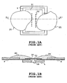
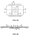
- A liquid-ejecting head, comprising:characterized in thatan orifice plate (11) having an array of a plurality of ejection orifices (10) through which a liquid is ejected;a plurality of energy-generating elements for generating energy to eject the liquid from respective ones of said ejection orifices (10);a wiring member for sending an electrical signal to said respective ones of said energy-generating elements;an exterior wiring portion (2) for applying said electrical signal to said wiring member;an electrically connected portion where said wiring member and said exterior wiring portion (2) are electrically connected together; anda sealing resin (21) that seals said electrically connected portion,
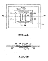
a first depression region (14) is provided on said orifice plate (11) to extend along said array of ejection orifices (10) between said array and said electrically connected portion such that said first depression region (14) prevented said sealing resin (21) from flowing over said depression region (14) to said ejection orifices (10),
and in that a second depression region (22) is provided on said exterior wiring portion (2), wherein said second depression region (22) extends in the same direction as said array of ejection orifices (10) and said first depression region (14) such that said second depression region (22) prevented said sealing resin (21) from flowing over said second depression region (22) in a direction away from said ejection orifices (10),
and wherein said second depression region (22) is longer than said first depression region. - The liquid-ejecting head as claimed in Claim 1, wherein
said electrically connected portion is formed on an extension of an arrangement direction of said array of ejection orifices (10), while said depression region (14) is in a shape of rectangular extending to a direction in parallel with said arrangement direction of said array of ejection orifices (10). - The liquid-ejecting head as claimed in Claim 1, characterized in that
said energy-generating elements are electrothermal transducer that generate heat for causing a film boiling phenomenon in said liquid. - A method of manufacturing a liquid-ejecting head that has:wherein said second depression region (22) is formed to be longer than said first depression region (14).an orifice plate (11) having an array of a plurality of ejection orifices (10) through which a liquid is ejected;a plurality of energy-generating elements for generating energy to eject the liquid from respective ones of said ejection orifices (10);a wiring member for sending an electrical signal to said respective ones of said energy-generating elements;an exterior wiring portion (2) for applying said electrical signal to said wiring member;an electrically connected portion where said wiring member and said exterior wiring portion (2) are electrically connected together; and a sealing resin that seals said electrically connected portion,the method being characterized by comprising a step of:forming a first depression region (14) on said orifice plate (11) to extend along said array of ejection orifices between said array and said electrically connected portion such that said depression region (14) prevents said sealing resin (21) from flowing over said first depression region (14, 15) to said ejection orifices (10), andforming a second depression region (22) on said exterior wiring portion (2), wherein said second depression region (22) extends in the same direction as said array of ejection orifices and said first depression region (14) such that said second depression region (22) prevents said sealing resin (21) from flowing over said second depression region (22) in a direction away from said ejection orifices (10),
- The method as claimed in Claim 4, wherein
said electrically connected portion is formed on an extension of an arrangement direction of said array of ejection orifices (10), while said first depression region (14) is formed in a shape of rectangular extending to a direction in parallel with said arrangement direction of said array of ejection orifices (10). - The method as claimed in Claim 4, wherein
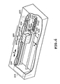
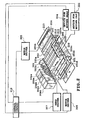
said energy-generating elements are electrothermal transducer that generate heat for causing a film boiling phenomenon in said liquid. - A liquid-ejecting apparatus for ejecting a liquid on a printing medium (P) to print, comprising:a carriage (200) that moves along a main-scanning direction, on which a liquid-ejecting head (201) for ejecting said liquid is removably mounted as a removable head or is fixed as a stationary head;a transporting means (207 to 211) for transporting said printing medium (P);a control means for controlling movements of said liquid-ejecting head (201) said carriage (200), and said transporting means (207 to 211), characterized in thatsaid liquid-ejecting head (201) is a liquid-ejecting head according to one of claims 1 to 3.
- The liquid-ejecting apparatus as claimed in Claim 7, wherein
said printing medium (P) is selected from a group of papers, cloth plastic materials, metal materials, leathers, lumber, and ceramic materials. - The liquid-ejecting apparatus as claimed in Claim 7, wherein
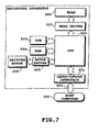
said liquid-ejecting head (201) ejects different colored liquids onto said printing medium (P) to perform a multicolor printing. - A printing system comprising:a control portion (219) for processing an input information; andan output means for outputting aprocessed information from said control portion, characterized in that said output means is a liquid ejecting apparatus according to Claim 7.
Applications Claiming Priority (3)
| Application Number | Priority Date | Filing Date | Title |
|---|---|---|---|
| JP20244796 | 1996-07-31 | ||
| JP8202447A JPH1044419A (en) | 1996-07-31 | 1996-07-31 | Liquid jet head, manufacture thereof, liquid jet unit, and recorder |
| JP202447/96 | 1996-07-31 |
Publications (3)
| Publication Number | Publication Date |
|---|---|
| EP0822077A2 EP0822077A2 (en) | 1998-02-04 |
| EP0822077A3 EP0822077A3 (en) | 1998-09-23 |
| EP0822077B1 true EP0822077B1 (en) | 2004-12-22 |
Family
ID=16457682
Family Applications (1)
| Application Number | Title | Priority Date | Filing Date |
|---|---|---|---|
| EP97113006A Expired - Lifetime EP0822077B1 (en) | 1996-07-31 | 1997-07-29 | Liquid-ejection head and method of manufacturing the same |
Country Status (4)
| Country | Link |
|---|---|
| US (1) | US6099109A (en) |
| EP (1) | EP0822077B1 (en) |
| JP (1) | JPH1044419A (en) |
| DE (1) | DE69732001T2 (en) |
Families Citing this family (20)
| Publication number | Priority date | Publication date | Assignee | Title |
|---|---|---|---|---|
| US6123410A (en) * | 1997-10-28 | 2000-09-26 | Hewlett-Packard Company | Scalable wide-array inkjet printhead and method for fabricating same |
| US5980682A (en) * | 1998-05-14 | 1999-11-09 | Lexmark International, Inc. | Thermal printhead manufacture |
| EP1095773B1 (en) * | 1999-10-29 | 2003-07-09 | Hewlett-Packard Company, A Delaware Corporation | Inkjet printhead having improved reliability |
| JP4632386B2 (en) * | 2000-12-21 | 2011-02-16 | キヤノン株式会社 | Liquid discharge recording head |
| US6520624B1 (en) * | 2002-06-18 | 2003-02-18 | Hewlett-Packard Company | Substrate with fluid passage supports |
| JP4332416B2 (en) * | 2003-12-12 | 2009-09-16 | キヤノン株式会社 | Inkjet recording head |
| DE102004004422A1 (en) * | 2004-01-29 | 2005-08-18 | Conti Temic Microelectronic Gmbh | Electronic device and method for bonding an electronic device |
| JP5038090B2 (en) * | 2006-12-21 | 2012-10-03 | キヤノン株式会社 | Liquid discharge head |
| US20080158298A1 (en) * | 2006-12-28 | 2008-07-03 | Serbicki Jeffrey P | Printhead wirebond encapsulation |
| JP2010000632A (en) * | 2008-06-18 | 2010-01-07 | Canon Inc | Substrate for inkjet head, and inkjet head equipped with substrate |
| JP5455575B2 (en) * | 2009-11-17 | 2014-03-26 | キヤノン株式会社 | Recording device |
| JP5528071B2 (en) * | 2009-11-25 | 2014-06-25 | キヤノン株式会社 | Liquid jet recording head and method of manufacturing liquid jet recording head |
| JP5665366B2 (en) * | 2010-05-17 | 2015-02-04 | キヤノン株式会社 | Recording device |
| JP6537312B2 (en) * | 2014-05-12 | 2019-07-03 | キヤノン株式会社 | Liquid discharge head, method of manufacturing the same, and liquid discharge apparatus |
| JP6604740B2 (en) * | 2014-05-30 | 2019-11-13 | キヤノン株式会社 | Method for manufacturing semiconductor substrate and substrate for liquid discharge head |
| EP3095613B1 (en) * | 2015-05-22 | 2019-11-27 | Agfa Nv | Manufacturing of decorative panels by inkjet |
| JP2016221777A (en) * | 2015-05-28 | 2016-12-28 | セイコーエプソン株式会社 | Liquid jet head unit, liquid jet device and wiping method |
| US10438864B2 (en) * | 2015-08-21 | 2019-10-08 | Hewlett-Packard Development Company, L.P. | Circuit packages comprising epoxy mold compounds and methods of compression molding |
| WO2019211070A1 (en) | 2018-05-03 | 2019-11-07 | Memjet Technology Limited | Inkjet printhead with encapsulant-retaining features |
| JP7146532B2 (en) * | 2018-09-05 | 2022-10-04 | キヤノン株式会社 | LIQUID EJECTION HEAD AND MANUFACTURING METHOD THEREOF |
Citations (1)
| Publication number | Priority date | Publication date | Assignee | Title |
|---|---|---|---|---|
| US5519421A (en) * | 1994-07-18 | 1996-05-21 | Hewlett-Packard Company | Disruption of polymer surface of a nozzle member to inhibit adhesive flow |
Family Cites Families (17)
| Publication number | Priority date | Publication date | Assignee | Title |
|---|---|---|---|---|
| JPS5459936A (en) * | 1977-10-03 | 1979-05-15 | Canon Inc | Recording method and device therefor |
| CA1127227A (en) * | 1977-10-03 | 1982-07-06 | Ichiro Endo | Liquid jet recording process and apparatus therefor |
| JPS5527282A (en) * | 1978-08-18 | 1980-02-27 | Canon Inc | Liquid injection recording method and its device |
| JPH064325B2 (en) * | 1984-06-11 | 1994-01-19 | キヤノン株式会社 | Liquid jet head |
| US4881318A (en) * | 1984-06-11 | 1989-11-21 | Canon Kabushiki Kaisha | Method of manufacturing a liquid jet recording head |
| JPH0822594B2 (en) * | 1984-10-19 | 1996-03-06 | キヤノン株式会社 | Inkjet recording head |
| US4860033A (en) * | 1987-02-04 | 1989-08-22 | Canon Kabushiki Kaisha | Base plate having an oxidation film and an insulating film for ink jet recording head and ink jet recording head using said base plate |
| JPH0216549A (en) * | 1988-07-05 | 1990-01-19 | Brother Ind Ltd | Image forming device |
| JPH04175728A (en) * | 1990-11-08 | 1992-06-23 | Minolta Camera Co Ltd | Solid scanning type optical print head |
| ATE144193T1 (en) * | 1990-12-12 | 1996-11-15 | Canon Kk | INKJET RECORDING |
| US5479197A (en) * | 1991-07-11 | 1995-12-26 | Canon Kabushiki Kaisha | Head for recording apparatus |
| DE69214548T2 (en) * | 1991-08-01 | 1997-03-13 | Canon Kk | Recording head manufacturing process |
| EP0585854B1 (en) * | 1992-08-31 | 1998-11-11 | Canon Kabushiki Kaisha | Ink jet head manufacturing method using ion machining and ink jet head manufactured thereby |
| JP3115720B2 (en) * | 1992-09-29 | 2000-12-11 | キヤノン株式会社 | INK JET PRINT HEAD, INK JET PRINTING APPARATUS HAVING THE PRINT HEAD, AND METHOD OF MANUFACTURING THE PRINT HEAD |
| US5343230A (en) * | 1992-11-20 | 1994-08-30 | Xerox Corporation | Electrical interconnect actuation which interacts with cap station articulation |
| US5896153A (en) * | 1994-10-04 | 1999-04-20 | Hewlett-Packard Company | Leak resistant two-material frame for ink-jet print cartridge |
| JP3459726B2 (en) * | 1996-06-14 | 2003-10-27 | キヤノン株式会社 | Ink jet recording head and method of manufacturing the same |
-
1996
- 1996-07-31 JP JP8202447A patent/JPH1044419A/en active Pending
-
1997
- 1997-07-29 US US08/902,325 patent/US6099109A/en not_active Expired - Lifetime
- 1997-07-29 DE DE69732001T patent/DE69732001T2/en not_active Expired - Lifetime
- 1997-07-29 EP EP97113006A patent/EP0822077B1/en not_active Expired - Lifetime
Patent Citations (1)
| Publication number | Priority date | Publication date | Assignee | Title |
|---|---|---|---|---|
| US5519421A (en) * | 1994-07-18 | 1996-05-21 | Hewlett-Packard Company | Disruption of polymer surface of a nozzle member to inhibit adhesive flow |
Also Published As
| Publication number | Publication date |
|---|---|
| JPH1044419A (en) | 1998-02-17 |
| EP0822077A2 (en) | 1998-02-04 |
| DE69732001D1 (en) | 2005-01-27 |
| DE69732001T2 (en) | 2005-12-15 |
| EP0822077A3 (en) | 1998-09-23 |
| US6099109A (en) | 2000-08-08 |
Similar Documents
| Publication | Publication Date | Title |
|---|---|---|
| EP0822077B1 (en) | Liquid-ejection head and method of manufacturing the same | |
| EP0822081B1 (en) | Liquid ejection head, liquid ejection head cartridge, printing apparatus, printing system and fabrication process of liquid ejection head | |
| US8517509B2 (en) | Liquid ejection head and image-forming apparatus using the same | |
| US6270199B1 (en) | Liquid ejecting head, liquid ejecting device and liquid ejecting method | |
| EP1057646A2 (en) | Forming ink images having a protection film | |
| EP0790129A2 (en) | Liquid ejection apparatus, head unit and ink-jet cartridge | |
| EP0895864B1 (en) | Liquid discharge method and liquid jet apparatus | |
| JP3667096B2 (en) | Inkjet recording apparatus and inkjet recording method | |
| JP3320317B2 (en) | Ink jet printing apparatus and printing method | |
| EP0750995B1 (en) | A method for ink-jet recording and an ink-jet recording apparatus | |
| JPH10278299A (en) | Ink jet recorder and method for ink jet recording | |
| JP3554099B2 (en) | Inkjet printing equipment | |
| EP0847872B1 (en) | Ink-jet printing method using first and second liquids, and printing apparatus for this method | |
| US6705700B2 (en) | Liquid discharge head, and head cartridge and image forming apparatus using such liquid discharge head | |
| US6179412B1 (en) | Liquid discharging head, having opposed element boards and grooved member therebetween | |
| JPH08336979A (en) | Color ink-jet recording device and recording method using the same | |
| EP0819535B1 (en) | Ink-jet textile printing method and apparatus therefor | |
| JP3554113B2 (en) | Liquid discharge head, method of manufacturing liquid discharge head, liquid discharge device, and recording system | |
| US6132031A (en) | Ink-jet head, ink-jet cartridge and ink-jet printing apparatus | |
| US6848769B2 (en) | Liquid ejecting head having a plurality of groups of ejection openings, and image-forming device using the same | |
| JP3176249B2 (en) | Ink jet recording head, ink jet recording apparatus, and information processing system | |
| JP3639698B2 (en) | Liquid discharge head, head cartridge, liquid discharge recording apparatus, and method of manufacturing liquid discharge head | |
| JPH11188862A (en) | Ink jet recording apparatus and ink jet recording method | |
| JPH054335A (en) | Recording device | |
| JP2003127374A (en) | Liquid ejection head, head cartridge, and image forming apparatus |
Legal Events
| Date | Code | Title | Description |
|---|---|---|---|
| PUAI | Public reference made under article 153(3) epc to a published international application that has entered the european phase |
Free format text: ORIGINAL CODE: 0009012 |
|
| AK | Designated contracting states |
Kind code of ref document: A2 Designated state(s): DE FR GB IT |
|
| AX | Request for extension of the european patent |
Free format text: AL;LT;LV;RO;SI |
|
| PUAL | Search report despatched |
Free format text: ORIGINAL CODE: 0009013 |
|
| AK | Designated contracting states |
Kind code of ref document: A3 Designated state(s): AT BE CH DE DK ES FI FR GB GR IE IT LI LU MC NL PT SE |
|
| AX | Request for extension of the european patent |
Free format text: AL;LT;LV;RO;SI |
|
| 17P | Request for examination filed |
Effective date: 19990208 |
|
| AKX | Designation fees paid |
Free format text: DE FR GB IT |
|
| RBV | Designated contracting states (corrected) |
Designated state(s): DE FR GB IT |
|
| 17Q | First examination report despatched |
Effective date: 20010206 |
|
| GRAP | Despatch of communication of intention to grant a patent |
Free format text: ORIGINAL CODE: EPIDOSNIGR1 |
|
| GRAS | Grant fee paid |
Free format text: ORIGINAL CODE: EPIDOSNIGR3 |
|
| GRAA | (expected) grant |
Free format text: ORIGINAL CODE: 0009210 |
|
| AK | Designated contracting states |
Kind code of ref document: B1 Designated state(s): DE FR GB IT |
|
| PG25 | Lapsed in a contracting state [announced via postgrant information from national office to epo] |
Ref country code: IT Free format text: LAPSE BECAUSE OF FAILURE TO SUBMIT A TRANSLATION OF THE DESCRIPTION OR TO PAY THE FEE WITHIN THE PRESCRIBED TIME-LIMIT;WARNING: LAPSES OF ITALIAN PATENTS WITH EFFECTIVE DATE BEFORE 2007 MAY HAVE OCCURRED AT ANY TIME BEFORE 2007. THE CORRECT EFFECTIVE DATE MAY BE DIFFERENT FROM THE ONE RECORDED. Effective date: 20041222 Ref country code: FR Free format text: LAPSE BECAUSE OF FAILURE TO SUBMIT A TRANSLATION OF THE DESCRIPTION OR TO PAY THE FEE WITHIN THE PRESCRIBED TIME-LIMIT Effective date: 20041222 |
|
| REG | Reference to a national code |
Ref country code: GB Ref legal event code: FG4D |
|
| REF | Corresponds to: |
Ref document number: 69732001 Country of ref document: DE Date of ref document: 20050127 Kind code of ref document: P |
|
| PLBE | No opposition filed within time limit |
Free format text: ORIGINAL CODE: 0009261 |
|
| STAA | Information on the status of an ep patent application or granted ep patent |
Free format text: STATUS: NO OPPOSITION FILED WITHIN TIME LIMIT |
|
| 26N | No opposition filed |
Effective date: 20050923 |
|
| EN | Fr: translation not filed | ||
| PGFP | Annual fee paid to national office [announced via postgrant information from national office to epo] |
Ref country code: DE Payment date: 20140731 Year of fee payment: 18 |
|
| PGFP | Annual fee paid to national office [announced via postgrant information from national office to epo] |
Ref country code: GB Payment date: 20140724 Year of fee payment: 18 |
|
| REG | Reference to a national code |
Ref country code: DE Ref legal event code: R119 Ref document number: 69732001 Country of ref document: DE |
|
| GBPC | Gb: european patent ceased through non-payment of renewal fee |
Effective date: 20150729 |
|
| PG25 | Lapsed in a contracting state [announced via postgrant information from national office to epo] |
Ref country code: GB Free format text: LAPSE BECAUSE OF NON-PAYMENT OF DUE FEES Effective date: 20150729 Ref country code: DE Free format text: LAPSE BECAUSE OF NON-PAYMENT OF DUE FEES Effective date: 20160202 |