EP0820853A2 - Filter assembly and method for making it - Google Patents
Filter assembly and method for making it Download PDFInfo
- Publication number
- EP0820853A2 EP0820853A2 EP97202282A EP97202282A EP0820853A2 EP 0820853 A2 EP0820853 A2 EP 0820853A2 EP 97202282 A EP97202282 A EP 97202282A EP 97202282 A EP97202282 A EP 97202282A EP 0820853 A2 EP0820853 A2 EP 0820853A2
- Authority
- EP
- European Patent Office
- Prior art keywords
- filter
- peaks
- wall portions
- along
- pleated
- Prior art date
- Legal status (The legal status is an assumption and is not a legal conclusion. Google has not performed a legal analysis and makes no representation as to the accuracy of the status listed.)
- Granted
Links
- 238000000034 method Methods 0.000 title claims abstract description 56
- 239000000463 material Substances 0.000 claims abstract description 62
- 238000001816 cooling Methods 0.000 claims abstract description 24
- 238000010438 heat treatment Methods 0.000 claims abstract description 14
- 239000003292 glue Substances 0.000 claims description 6
- 239000004033 plastic Substances 0.000 claims description 4
- 229920003023 plastic Polymers 0.000 claims description 4
- 230000001681 protective effect Effects 0.000 claims description 4
- 239000011248 coating agent Substances 0.000 claims description 3
- 238000000576 coating method Methods 0.000 claims description 3
- 239000002657 fibrous material Substances 0.000 claims description 3
- 238000007373 indentation Methods 0.000 claims description 3
- 239000004593 Epoxy Substances 0.000 claims description 2
- 239000004568 cement Substances 0.000 claims description 2
- 239000000203 mixture Substances 0.000 claims description 2
- 239000003973 paint Substances 0.000 claims description 2
- 230000001965 increasing effect Effects 0.000 description 5
- 238000005096 rolling process Methods 0.000 description 4
- 239000012530 fluid Substances 0.000 description 3
- 239000000853 adhesive Substances 0.000 description 2
- 230000001070 adhesive effect Effects 0.000 description 2
- 229910052782 aluminium Inorganic materials 0.000 description 2
- 239000011324 bead Substances 0.000 description 2
- 230000002708 enhancing effect Effects 0.000 description 2
- 239000007789 gas Substances 0.000 description 2
- 230000004048 modification Effects 0.000 description 2
- 238000012986 modification Methods 0.000 description 2
- 239000013618 particulate matter Substances 0.000 description 2
- 239000011253 protective coating Substances 0.000 description 2
- 230000000712 assembly Effects 0.000 description 1
- 238000000429 assembly Methods 0.000 description 1
- 230000015572 biosynthetic process Effects 0.000 description 1
- 238000010924 continuous production Methods 0.000 description 1
- 238000006073 displacement reaction Methods 0.000 description 1
- 239000004744 fabric Substances 0.000 description 1
- 230000006870 function Effects 0.000 description 1
- 238000005304 joining Methods 0.000 description 1
- 238000004519 manufacturing process Methods 0.000 description 1
- 229910052751 metal Inorganic materials 0.000 description 1
- 239000002184 metal Substances 0.000 description 1
- 239000004745 nonwoven fabric Substances 0.000 description 1
- 239000000123 paper Substances 0.000 description 1
- 238000004904 shortening Methods 0.000 description 1
- 238000003860 storage Methods 0.000 description 1
- 239000002759 woven fabric Substances 0.000 description 1
Images


Classifications
-
- B—PERFORMING OPERATIONS; TRANSPORTING
- B01—PHYSICAL OR CHEMICAL PROCESSES OR APPARATUS IN GENERAL
- B01D—SEPARATION
- B01D46/00—Filters or filtering processes specially modified for separating dispersed particles from gases or vapours
- B01D46/52—Particle separators, e.g. dust precipitators, using filters embodying folded corrugated or wound sheet material
- B01D46/521—Particle separators, e.g. dust precipitators, using filters embodying folded corrugated or wound sheet material using folded, pleated material
-
- B—PERFORMING OPERATIONS; TRANSPORTING
- B01—PHYSICAL OR CHEMICAL PROCESSES OR APPARATUS IN GENERAL
- B01D—SEPARATION
- B01D25/00—Filters formed by clamping together several filtering elements or parts of such elements
- B01D25/001—Making filtering elements not provided for elsewhere
-
- B—PERFORMING OPERATIONS; TRANSPORTING
- B01—PHYSICAL OR CHEMICAL PROCESSES OR APPARATUS IN GENERAL
- B01D—SEPARATION
- B01D25/00—Filters formed by clamping together several filtering elements or parts of such elements
- B01D25/22—Cell-type filters
- B01D25/26—Cell-type stack filters
-
- B—PERFORMING OPERATIONS; TRANSPORTING
- B01—PHYSICAL OR CHEMICAL PROCESSES OR APPARATUS IN GENERAL
- B01D—SEPARATION
- B01D29/00—Filters with filtering elements stationary during filtration, e.g. pressure or suction filters, not covered by groups B01D24/00 - B01D27/00; Filtering elements therefor
- B01D29/01—Filters with filtering elements stationary during filtration, e.g. pressure or suction filters, not covered by groups B01D24/00 - B01D27/00; Filtering elements therefor with flat filtering elements
- B01D29/012—Making filtering elements
-
- B—PERFORMING OPERATIONS; TRANSPORTING
- B01—PHYSICAL OR CHEMICAL PROCESSES OR APPARATUS IN GENERAL
- B01D—SEPARATION
- B01D29/00—Filters with filtering elements stationary during filtration, e.g. pressure or suction filters, not covered by groups B01D24/00 - B01D27/00; Filtering elements therefor
- B01D29/01—Filters with filtering elements stationary during filtration, e.g. pressure or suction filters, not covered by groups B01D24/00 - B01D27/00; Filtering elements therefor with flat filtering elements
- B01D29/016—Filters with filtering elements stationary during filtration, e.g. pressure or suction filters, not covered by groups B01D24/00 - B01D27/00; Filtering elements therefor with flat filtering elements with corrugated, folded or wound filtering elements
-
- B—PERFORMING OPERATIONS; TRANSPORTING
- B01—PHYSICAL OR CHEMICAL PROCESSES OR APPARATUS IN GENERAL
- B01D—SEPARATION
- B01D29/00—Filters with filtering elements stationary during filtration, e.g. pressure or suction filters, not covered by groups B01D24/00 - B01D27/00; Filtering elements therefor
- B01D29/11—Filters with filtering elements stationary during filtration, e.g. pressure or suction filters, not covered by groups B01D24/00 - B01D27/00; Filtering elements therefor with bag, cage, hose, tube, sleeve or like filtering elements
- B01D29/111—Making filtering elements
-
- B—PERFORMING OPERATIONS; TRANSPORTING
- B01—PHYSICAL OR CHEMICAL PROCESSES OR APPARATUS IN GENERAL
- B01D—SEPARATION
- B01D29/00—Filters with filtering elements stationary during filtration, e.g. pressure or suction filters, not covered by groups B01D24/00 - B01D27/00; Filtering elements therefor
- B01D29/11—Filters with filtering elements stationary during filtration, e.g. pressure or suction filters, not covered by groups B01D24/00 - B01D27/00; Filtering elements therefor with bag, cage, hose, tube, sleeve or like filtering elements
- B01D29/13—Supported filter elements
- B01D29/15—Supported filter elements arranged for inward flow filtration
- B01D29/21—Supported filter elements arranged for inward flow filtration with corrugated, folded or wound sheets
-
- B—PERFORMING OPERATIONS; TRANSPORTING
- B01—PHYSICAL OR CHEMICAL PROCESSES OR APPARATUS IN GENERAL
- B01D—SEPARATION
- B01D29/00—Filters with filtering elements stationary during filtration, e.g. pressure or suction filters, not covered by groups B01D24/00 - B01D27/00; Filtering elements therefor
- B01D29/11—Filters with filtering elements stationary during filtration, e.g. pressure or suction filters, not covered by groups B01D24/00 - B01D27/00; Filtering elements therefor with bag, cage, hose, tube, sleeve or like filtering elements
- B01D29/13—Supported filter elements
- B01D29/23—Supported filter elements arranged for outward flow filtration
- B01D29/232—Supported filter elements arranged for outward flow filtration with corrugated, folded or wound sheets
-
- B—PERFORMING OPERATIONS; TRANSPORTING
- B01—PHYSICAL OR CHEMICAL PROCESSES OR APPARATUS IN GENERAL
- B01D—SEPARATION
- B01D29/00—Filters with filtering elements stationary during filtration, e.g. pressure or suction filters, not covered by groups B01D24/00 - B01D27/00; Filtering elements therefor
- B01D29/50—Filters with filtering elements stationary during filtration, e.g. pressure or suction filters, not covered by groups B01D24/00 - B01D27/00; Filtering elements therefor with multiple filtering elements, characterised by their mutual disposition
- B01D29/52—Filters with filtering elements stationary during filtration, e.g. pressure or suction filters, not covered by groups B01D24/00 - B01D27/00; Filtering elements therefor with multiple filtering elements, characterised by their mutual disposition in parallel connection
-
- B—PERFORMING OPERATIONS; TRANSPORTING
- B01—PHYSICAL OR CHEMICAL PROCESSES OR APPARATUS IN GENERAL
- B01D—SEPARATION
- B01D46/00—Filters or filtering processes specially modified for separating dispersed particles from gases or vapours
- B01D46/0001—Making filtering elements
-
- B—PERFORMING OPERATIONS; TRANSPORTING
- B01—PHYSICAL OR CHEMICAL PROCESSES OR APPARATUS IN GENERAL
- B01D—SEPARATION
- B01D46/00—Filters or filtering processes specially modified for separating dispersed particles from gases or vapours
- B01D46/10—Particle separators, e.g. dust precipitators, using filter plates, sheets or pads having plane surfaces
-
- B—PERFORMING OPERATIONS; TRANSPORTING
- B29—WORKING OF PLASTICS; WORKING OF SUBSTANCES IN A PLASTIC STATE IN GENERAL
- B29C—SHAPING OR JOINING OF PLASTICS; SHAPING OF MATERIAL IN A PLASTIC STATE, NOT OTHERWISE PROVIDED FOR; AFTER-TREATMENT OF THE SHAPED PRODUCTS, e.g. REPAIRING
- B29C61/00—Shaping by liberation of internal stresses; Making preforms having internal stresses; Apparatus therefor
- B29C61/06—Making preforms having internal stresses, e.g. plastic memory
- B29C61/0608—Making preforms having internal stresses, e.g. plastic memory characterised by the configuration or structure of the preforms
-
- B—PERFORMING OPERATIONS; TRANSPORTING
- B01—PHYSICAL OR CHEMICAL PROCESSES OR APPARATUS IN GENERAL
- B01D—SEPARATION
- B01D2201/00—Details relating to filtering apparatus
- B01D2201/12—Pleated filters
-
- B—PERFORMING OPERATIONS; TRANSPORTING
- B01—PHYSICAL OR CHEMICAL PROCESSES OR APPARATUS IN GENERAL
- B01D—SEPARATION
- B01D2201/00—Details relating to filtering apparatus
- B01D2201/46—Several filtrate discharge conduits each connected to one filter element or group of filter elements
-
- B—PERFORMING OPERATIONS; TRANSPORTING
- B01—PHYSICAL OR CHEMICAL PROCESSES OR APPARATUS IN GENERAL
- B01D—SEPARATION
- B01D2279/00—Filters adapted for separating dispersed particles from gases or vapours specially modified for specific uses
- B01D2279/60—Filters adapted for separating dispersed particles from gases or vapours specially modified for specific uses for the intake of internal combustion engines or turbines
-
- B—PERFORMING OPERATIONS; TRANSPORTING
- B29—WORKING OF PLASTICS; WORKING OF SUBSTANCES IN A PLASTIC STATE IN GENERAL
- B29C—SHAPING OR JOINING OF PLASTICS; SHAPING OF MATERIAL IN A PLASTIC STATE, NOT OTHERWISE PROVIDED FOR; AFTER-TREATMENT OF THE SHAPED PRODUCTS, e.g. REPAIRING
- B29C53/00—Shaping by bending, folding, twisting, straightening or flattening; Apparatus therefor
- B29C53/02—Bending or folding
-
- B—PERFORMING OPERATIONS; TRANSPORTING
- B29—WORKING OF PLASTICS; WORKING OF SUBSTANCES IN A PLASTIC STATE IN GENERAL
- B29L—INDEXING SCHEME ASSOCIATED WITH SUBCLASS B29C, RELATING TO PARTICULAR ARTICLES
- B29L2016/00—Articles with corrugations or pleats
-
- B—PERFORMING OPERATIONS; TRANSPORTING
- B29—WORKING OF PLASTICS; WORKING OF SUBSTANCES IN A PLASTIC STATE IN GENERAL
- B29L—INDEXING SCHEME ASSOCIATED WITH SUBCLASS B29C, RELATING TO PARTICULAR ARTICLES
- B29L2031/00—Other particular articles
- B29L2031/14—Filters
-
- Y—GENERAL TAGGING OF NEW TECHNOLOGICAL DEVELOPMENTS; GENERAL TAGGING OF CROSS-SECTIONAL TECHNOLOGIES SPANNING OVER SEVERAL SECTIONS OF THE IPC; TECHNICAL SUBJECTS COVERED BY FORMER USPC CROSS-REFERENCE ART COLLECTIONS [XRACs] AND DIGESTS
- Y10—TECHNICAL SUBJECTS COVERED BY FORMER USPC
- Y10S—TECHNICAL SUBJECTS COVERED BY FORMER USPC CROSS-REFERENCE ART COLLECTIONS [XRACs] AND DIGESTS
- Y10S493/00—Manufacturing container or tube from paper; or other manufacturing from a sheet or web
- Y10S493/941—Filter
-
- Y—GENERAL TAGGING OF NEW TECHNOLOGICAL DEVELOPMENTS; GENERAL TAGGING OF CROSS-SECTIONAL TECHNOLOGIES SPANNING OVER SEVERAL SECTIONS OF THE IPC; TECHNICAL SUBJECTS COVERED BY FORMER USPC CROSS-REFERENCE ART COLLECTIONS [XRACs] AND DIGESTS
- Y10—TECHNICAL SUBJECTS COVERED BY FORMER USPC
- Y10T—TECHNICAL SUBJECTS COVERED BY FORMER US CLASSIFICATION
- Y10T156/00—Adhesive bonding and miscellaneous chemical manufacture
- Y10T156/10—Methods of surface bonding and/or assembly therefor
- Y10T156/1002—Methods of surface bonding and/or assembly therefor with permanent bending or reshaping or surface deformation of self sustaining lamina
- Y10T156/1007—Running or continuous length work
- Y10T156/1015—Folding
-
- Y—GENERAL TAGGING OF NEW TECHNOLOGICAL DEVELOPMENTS; GENERAL TAGGING OF CROSS-SECTIONAL TECHNOLOGIES SPANNING OVER SEVERAL SECTIONS OF THE IPC; TECHNICAL SUBJECTS COVERED BY FORMER USPC CROSS-REFERENCE ART COLLECTIONS [XRACs] AND DIGESTS
- Y10—TECHNICAL SUBJECTS COVERED BY FORMER USPC
- Y10T—TECHNICAL SUBJECTS COVERED BY FORMER US CLASSIFICATION
- Y10T156/00—Adhesive bonding and miscellaneous chemical manufacture
- Y10T156/10—Methods of surface bonding and/or assembly therefor
- Y10T156/1002—Methods of surface bonding and/or assembly therefor with permanent bending or reshaping or surface deformation of self sustaining lamina
- Y10T156/1051—Methods of surface bonding and/or assembly therefor with permanent bending or reshaping or surface deformation of self sustaining lamina by folding
Definitions
- the present invention relates to a filter assembly, particularly a filter pack structure and a method for forming same.
- Filters for air and other gases are commonly used in hostile environments and typically require a high degree of structural integrity and performance characteristics.
- Conventional filters for example for gas turbine and compressor intake equipment and the like, typically use a filter pack formed from a filter media.
- filters such as those described above include a casing or housing member which contains the filter pack formed from suitable filter media.
- the function of the filter pack is to filter air passing through the filter. It is desirable to position the filter media within the housing in such a way as to provide as low a pressure drop across the filter as possible. Pressure drop across the filter is attributed to two primary sources.
- the first source is called a media pressure drop (MPD) and refers to the pressure drop caused by the filter media. Since this pressure drop is related to the velocity of air passing through the filter media, the media pressure drop is reduced as the area of filter media through which air passes is increased.
- MPD media pressure drop
- the other source of filter pressure drop is the configuration pressure drop (CPD), which is a pressure drop caused by the configuration of filter media within the casing or housing which obstructs flow therethrough.
- CPD configuration pressure drop
- Figure 1 shows a simple filter media configuration wherein the media pressure drop is relatively high due to a high air to media ratio.
- the configuration pressure drop of the configuration of Figure 1 is very low or negligible due to an absence of obstacles to air flow through the filter.
- the filter media is provided in a zig-zag pattern allowing more media to be disposed within the same casing space.
- This configuration is referred to in the industry as an extended surface filter.
- the configuration provides a lower air to media ratio which produces a lower media pressure drop than the configuration of Figure 1.
- the configuration of Figure 2 does not create a significant configuration pressure drop.
- the filter pressure drop of the configuration of Figure 2 would be lower and therefore more preferable than the filter pressure drop of Figure 1.
- Figure 3 shows a configuration wherein a very large amount of filter media is disposed within the casing, so as to provide a very low media pressure drop.
- the configuration of the filter media is so congested as to create a large configuration pressure drop which would practically inhibit any flow whatsoever through the filter.
- the large configuration pressure drop of the configuration of Figure 3 would provide this filter with an unacceptably high filter pressure drop.
- a problem encountered with providing filter media in a configuration such as that shown in Figure 2 is the problem associated with maintaining the filter media in a desired configuration.
- some form of structure is required to enhance the rigidity of the filter media.
- One method for enhancing the rigidity of a filter configuration such as that of Figure 2 is to apply an open and rigid backing to the media such as a wire mesh or expanded metal.
- application of such a backing to the filter media significantly impedes pleating or folding of the media to desired configurations.
- Another method for enhancing the rigidity of such filter media is to place separators between filter media pleats or folds so that the media is kept in place and does not collapse due to air flow.
- the separator elements required for this solution add an additional source of cost to the filter, and also contribute to the configuration pressure drop.
- Another approach to solving the rigidity problem of the filter media is to apply a glue bead to the filter media after it has been pleated or folded, and the glue bead is intended to separate the pleats of media sufficiently to allow a low flow of air. This is suitable for some very high efficiency air filters handling low rates of air flow. However, this approach does not allow for a large air flow rate through the filter.
- a method for making a pleated structure having shape memory comprises the steps of providing a material in a pleated structure having a plurality of substantially parallel folds; folding the material along a plurality of axes substantially perpendicular to the first plurality of folds so as to provide a folded structure defining wall portions between folds along the plurality of axes and having face portions at the folds; heating the material in the pleated structure so as to provide a heated material; and cooling the heated material so as to provide the material with shape memory toward the pleated structure.
- a method for forming a filter pack structure wherein the material is a filter media and the folding step provides a filter pack having a zig-zag folded structure.
- a filter pack structure which comprises a filter media folded along a plurality of axes in a substantially zig-zag folded structure to provide a plurality of wall portions connected at alternating edges by face portions, and having a pleated structure including pleats along fold lines substantially perpendicular to the axes to provide each wall portion and face portion with alternating peaks and valleys, wherein the filter media has shape memory toward the pleated structure.
- the invention relates generally to a pleated structure having shape memory and more specifically to a filter pack structure and method for forming same which advantageously provide a rigid filter pack structure formed from filter media which filter pack structure allows a large amount of filter media to be placed in a filter casing while providing a low filter pressure drop as desired.
- Figures 1-3 illustrate several configurations of filter media disposed within a filter casing and providing various levels of media pressure drop and configuration pressure drop.
- the configuration of Figure 1 has the highest media pressure drop and the configuration of Figure 3 has the highest configuration pressure drop.
- the configuration of Figure 2 provides the most advantageous overall filter pressure drop of the configurations illustrated.
- a filter pack structure and method for forming same are provided which advantageously result in a low media pressure drop and also in a low configuration pressure drop, thereby providing an advantageously low total filter pressure drop.
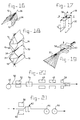
- filter pack structure 10 preferably is formed from a suitable filter media which is folded into a substantially zig-zag pattern so as to define a plurality of wall portions 12 connected at alternating edges 14 by face portions 16.
- the filter media of filter pack structure 10 is pleated, according to the invention, so as to provide each wall portion 12 with alternating peaks 18 and valleys 20 as shown. Further, the folding of filter pack structure 10 provides wall portions 12 wherein the peaks 18 of adjacent wall portions 12 are substantially adjacent to each other.
- filter pack structure 10 is positioned with alternating face portions 16a facing toward an incoming flow of air or other fluid to be filtered as shown in Figure 4, and with remaining face portions 16b on the air leaving or outlet side of filter pack structure 10.
- the filter media of filter pack structure 10 is pleated so as to provide peaks 18 and valleys 20 and then treated so as to provide the filter media with a set or shape memory which urges the material toward the pleated structure. This is desirable so as to provide filter pack structure 10 with enhanced rigidity so as to resist shifting or undesirable displacement within a filter casing due to air flow and to provide a filter pack structure 10 which readily folds into shape. Also as will be discussed, the filter media of the present invention is preferably provided with the desired set or shape memory through a heating and cooling step. It should be noted, of course, that other methods for providing the material with the desired set could be used in accordance with the present invention depending upon the materials used as filter media.
- Figure 5 is a schematic view taken along the cross-section of lines 5-5 of Figure 4 and shows a section of filter pack structure 10 having a number of wall portions 12.
- Figure 5 further illustrates the substantially adjacent positioning of peaks 18 of adjacent wall portions 12. This is desirable in accordance with the present invention as contact of adjacent peaks 18 serves to further support the filter media of filter pack structure 10 in a desired configuration against shifting or collapsing.
- peaks 18 of adjacent wall portions 12 rest loosely against each other and support one another when wall portions 12 are biased toward each other.
- adjacent peaks 18 can be secured or bonded together as shown in Figure 6, for example, with glue 22 or any other suitable adhesive.
- peaks 18 could be thermally bonded together.
- numerous methods are known by which adjacent peaks 18 could be secured to each other and the term bonding when used to refer to the attachment of adjacent peaks 18 is not intended to indicate any specific means for affixing. Rather, any suitable method for joining peaks 18 of the filter media used is intended to fall within the scope of the term bonding as used herein.
- the structure illustrated in Figure 6 serves to further advantageously provide filter pack 10 with enhanced rigidity as desired.
- FIG 7 a further alternative embodiment of the present invention is illustrated wherein wall portions 12 are provided with pleats so as to form peaks 18a and valleys 20a from a double fold thereby defining substantially flat peak surfaces 24 and substantially flat valley surfaces 26.
- Substantially flat peak surfaces 24 are advantageous in that additional surface area is provided for adjacent wall portions 12 to support each other.
- the flat peak surface structure of this embodiment may be provided to filter pack structure 10 in accordance with the invention as shown Figure 19 through the application of heat and pressure. This process will be further discussed below.
- adjacent peak surfaces 24 could be bonded together for additional rigidity in accordance with the present invention if desired.
- separator members 28 are positioned between adjacent wall portions 12 so as to further enhance the rigidity and resistance to collapse of structure 10.
- Separator members 28 are preferably provided from any suitable material such as, for example, filter media, cardboard, metal-aluminum, plastic and the like, and may be provided as substantially flat structures as illustrated in Figure 8, or any of a wide variety of alternative structures which serve to hold wall portions 12 in position in accordance with the invention.
- separators could be provided from cord or wire materials, and the like.
- separator members 28 could be bonded to adjacent peaks 18 for still further enhanced rigidity, if desired.
- Figure 9 shows a portion of a filter pack structure 10, specifically a face portion 16 thereof.
- some face portions 16a of filter pack structure 10 will be facing toward the incoming air flow directed to the filter casing in which filter pack structure 10 is positioned. Obviously, these face portions 16a are subjected to increased wear due to impingement of entrained particulate matter and the like carried by air to be filtered with filter pack structure 10.
- filter pack structures generally are protected with a screen member positioned at the inlet of the filter to remove the largest of such particulate matter.
- face portions 16 may suitably be treated with a wear resistant coating 30 such as a glue, epoxy, plastic, cement, paint and the like, or mixtures thereof, so as to protect face portions 16 from impingement by the air flow, and reduce or eliminate the need for protective screens at the inlet of the filter. It is particularly desirable to treat face portions 16 on the air inlet side of a filter pack structure 10 which are subjected to wear from incoming air or fluid to be filtered.
- the provision or application of protective coating 30 in accordance with the present invention also advantageously serves to enhance the rigidity of filter pack structure 10 by providing a set for filter pack structure 10 to retain the fold structure defining face portions 16.
- the embodiments of the present invention discussed above provide a filter pack structure 10 which advantageously possesses enhanced structural rigidity and therefore resists undesirable shifting or collapsing due to flow through the filter. It should also be noted that variable flow rates are a problem in the industry, and such flows tend to further cause filter collapse and the like.
- the enhanced rigidity provided by the structure of the present invention further serves to allow filter pack structure 10 to be used to filter variable flow rates of air or other fluid with further enhanced resistance to filter collapse.
- filter media 32 is preferably provided in a substantially elongate or web structure as will be further discussed below, a portion of which is illustrated in Figure 10.
- Figure 10 shows filter media 32 preferably scored along longitudinal fold lines 34 to provide for subsequent pleating.
- Filter media 32 is preferably also scored along a number of axes 36 which are preferably substantially perpendicular to fold lines 34 and which are to form the basis for folding into the substantially zig-zag shaped filter pack structure 10 also as will be further described below.
- Scoring may be carried out using conventional scoring equipment which may also provide for scoring using heat if desired. Further, scoring or heated scoring may be performed initially, intermediately, or as a final step in the production of a filter pack structure 10 in accordance with the present invention, or at several of these stages.
- scoring along axes 36 is preferably provided in a substantially diamond-shaped pattern centered along axis 36.
- the diamond-shaped pattern is preferably provided with adjacent points 38 of individual diamond-shapes contacting one another and positioned on axes 36 as shown.
- Filter media 32 is preferably scored along axes 36 at a spacing between axes 36 defining the desired length of wall portions 12.
- filter media 32 is preferably pleated, most preferably after scoring, so as to define alternating peaks 18 and valleys 20 running longitudinally along the length of filter media 32 as shown.
- Pleating can also be carried out using conventional pleating equipment, and may be carried out simultaneously with the application of heat as the beginning of or a part of the heating step to provide shape memory.
- filter media 32 is treated after pleating to provide filter media 32 with a set which is biased toward the pleated or folded condition.
- Figure 12 schematically shows a heat applying station 40 and a cooling station 42.
- filter media 32 is provided with a set which tends toward the pleated shape rather than the original starting flat shape.
- this set of the filter media material is desirable so as to further enhance the rigidity of the final filter pack structure 10 which is formed in accordance with the method of the present invention.
- suitable filter media may include fibrous or non-fibrous material, woven or non-woven fabric, paper, cloth, metal-aluminum, plastics and the like.
- a particularly suitable example of filter media for use in accordance with the invention is a material identified as Hollingsworth & Vose Media HF0393.
- HF0393 filter media has been found to adopt a suitable shape memory or set through the application of heat at a temperature of at least about 460°F for at least about 3 minutes. Of course, other materials may have significantly different temperatures and times of exposure during which acceptable set or shape memory is accomplished.
- Cooling station 42 for positively cooling the heated filter media, it is within the scope of the present invention to simply allow heated filter media 32 to cool passively to the desired temperature. Cooling station 42 is advantageous, however, in that cooling is accomplished in less time thereby shortening the overall path length required to form filter pack structure 10 in accordance with the invention.
- filter media 32 is preferably spread laterally along axes 36 as shown, and then folded along axes 36 in alternating directions so as to provide the desired final zig-zag configuration of filter pack structure 10 according to the invention. After folding along axes 36, filter media 32 is laterally released allowing the material to return to the set pleated structure forming face portions 16 at the folds along axes 36 which also have peaks 18 and valleys 20 as shown in Figures 4 and 9.
- filter media 32 is preferably folded in alternating opposite directions until a sufficient number of folds and resulting wall portions 12 are defined, at which point filter pack structure 10 is provided and ready for positioning within a filter casing structure according to the invention.
- Figures 15-17 illustrate an alternative method for forming a filter pack structure 10 in accordance with the present invention.
- Figure 15 shows an initial scoring step including substantially parallel fold lines 34 as shown.
- a diamond-shaped scoring pattern is preferably centered around axes 36.
- additional straight fold lines 44 are also preferably scored into filter media 32, preferably substantially parallel to axes 36 and spaced to either side thereof so as to coincide with the longitudinally extending points 46 of the scored diamond-shapes.
- filter media 32 is pleated as shown in Figure 11 and in an identical procedure as that discussed above.
- the pleated structure is then preferably treated as illustrated in Figure 12 so as to provide filter media 32 with a set toward the pleated condition.
- pleated and set filter media 32 is then preferably folded along fold lines 44, and forces A, B and C are applied to face portions 16 of filter media 32 as shown in Figure 17.
- Force A is preferably applied at the location where points 38 cross and coincide with axes 36 while forces B and C are preferably inwardly applied to edges of face portion 16 at score lines corresponding to valleys 20 aligned with points 38.
- This advantageously provides filter pack structure 10 with face portions 16 as shown in Figure 18 having further enhanced rigidity as desired in accordance with the present invention.
- Application of forces A, B and C result in face portions 16 having a series of substantially X-shaped or hour-glass-shaped indentations 21 divided by peaks 19 positioned therebetween.
- This configuration also advantageously serves to provide face portions 16 of filter structure 10 with enhanced rigidity as desired.
- heating and cooling step as illustrated in Figure 12 is described above as being carried out after the material is pleated. It is noted that heating and cooling could be carried out at other specific time periods or after other steps in the method of the present invention, or in several stages or discrete steps if desired. For example, heating and cooling may be performed at the end of the process, after pleated filter media is folded along axes 36 to the desired end zig-zag shaped structure.
- FIG. 19 illustrates a method for providing substantially flat surfaces 24, 26 of peaks and valleys in accordance with the invention.
- a pleated web may suitably be fed first to a heating station 58 where the web is heated to a temperature sufficient for providing the material of the web, upon cooling, with shape memory as desired, and is subsequently fed to a pressure roller station 60 for pressure rolling peaks 18 into substantially flat peak surfaces 24.
- substantially flat surfaces 24 Upon cooling, substantially flat surfaces 24 have shape memory toward the desired configuration.
- a wide number of alternative methods may be used to provide substantially flat surfaces 24, 26 as desired in accordance with the invention.
- filter media 32 may preferably be provided for example from a feed roll 48 and provided as a substantially continuous web 50 which is fed to various stations for treatment as discussed above.
- web 50 of filter media 32 may suitably first be fed to a scoring station 52 (shown schematically) so as to provide a scored web material having scoring as discussed above in connection with Figures 10 and 15.
- scored filter media is fed to a pleating station 54 for carrying out pleating as shown and discussed with respect to Figure 11.
- the pleated web is then preferably fed to a heat applying station 40, preferably followed by cooling station 42 or alternatively by a passive cooling period so as to provide pleated web 50 with the desired pleated set.
- web 50 with the pleated set or shape memory is then fed to a folding station 56 for folding along axes 36 so as to provide filter pack structure 10 having the desired zig-zag structure of wall portions 12 joined by face portions 16 at alternating edges 14 of wall portions 12.
- one or more additional stations could be provided in the system shown in Figure 20 for carrying out additional steps such as applying glue or other adhesive material to bond adjacent peaks 18, or for applying protective coating to face portions 16, or for carrying out any other additional processing steps as desired in accordance with the present invention.
- the scoring steps, with or without heat, as discussed above render the pleating and folding steps of the method of the present invention more accurate and readily performed.
- the filter media may be pleated and folded into the filter pack structure 10 of the present invention without an initial scoring step if desired.
- the present invention is not specifically limited to requiring a scoring step.
- filter media 62 may suitably be fed to a rolling station 64 after folding at folding station 56 so as to provide filter media in a roll 66 convenient for shipping, storage and subsequent unrolling for folding into filter pack structure as desired.
- media 62 is preferably treated to provide shape memory toward the folded structure, and then unfolded and rolled.
- media 62 may be scored or heat scored along axes 36 and fed from pleating station 54 to rolling station 64 without folding, if desired.
- filter pack structure 10 formed in accordance with the present invention provides an excellent overall filter pressure drop by advantageously reducing the ratio of air flow to filter area, or air-media ratio, while maintaining a relatively low configuration pressure drop.
Abstract
Description
Application of forces A, B and C result in
Claims (39)
- Method for making a pleated structure having a pleated shape memory, comprising the steps of:providing a material in a pleated structure having a plurality of substantially parallel folds;folding the material along a plurality of axes substantially perpendicular to the first plurality of folds so as to provide a folded structure defining wall portions between folds along the plurality of axes and having face portions at the folds;heating tne material in the pleated structure so as to provide a heated material; andcooling the heated material so as to provide the material with shape memory toward the pleated structure.
- Method according to claim 1, comprising the steps of heating and cooling the material in the folded structure so as to provide the material with shape memory toward the folded structure.
- Method according to claim 2, comprising heating and cooling the material in a pleated and folded structure so as to provide the material with shape memory to the pleated and folded structure.
- Method according to one of the preceding claims wherein the cooling step comprises allowing the heated material to cool.
- Method according to one of the preceding claims wherein the cooling step comprises positively cooling the heated material.
- Method according to one of the preceding claims, wherein the step of providing the material comprises scoring the material along lines corresponding to the first plurality of substantially parallel folds, and pleating the material by folding in alternating opposite directions along the lines.
- Method according to claim 6, further comprising the step of scoring the material in a substantially diamond-shaped pattern centered along each axis of the plurality of axes.
- Method according to claim 7, wherein the scoring step comprises scoring the material in a substantially diamond-shaped pattern centered along each axis of the plurality of axes so as to provide a series of diamond-shaped score lines arranged along each axis and meeting at adjacent points with the adjacent points positioned on an axis of the plurality of axes, and scoring the material along a second plurality of transverse lines substantially perpendicular to the first plurality of folds and spaced to each side of each axis.
- Method according to claim 8, further comprising the steps of applying force to the face portions of the folded structure at the adjacent points and to the wall portions at valleys corresponding to the adjacent points so as to provide the face portions with a series of substantially X-shaped indentations separated by peaks.
- Method according to one of the preceding claims wherein the material is a filter media and the folding step provides a filter pack having a substantially zig-zag folded structure.
- Method according to claim 10, wherein the pleats of each wall portion define a series of alternating peaks and valleys, and wherein the folding step provides the filter pack with peaks of adjacent wall portions substantially adjacent to each other whereby spacing of the wall portions is maintained.
- Method according to claim 11, further comprising the step of bonding peaks of adjacent wall portions which are substantially adjacent to each other together so as to enhance rigidity of the filter pack.
- Method according to one of the claims 10-12, further comprising the step of providing separators between adjacent wall portions so as to enhance rigidity of the filter pack.
- Method according to claim 13, wherein the pleats of each wall portion define a series of alternating peaks and valleys, wherein the folding step provides the filter pack with peaks of adjacent wall portions substantially adjacent to each other, and wherein the step of providing separators comprises positioning a substantially flat sheet between the peaks of adjacent wall portions.
- Method according to claim 14, further comprising the step of bonding peaks of the wall portions to separators positioned therebetween.
- Method according to one of the claims 10-15, wherein the pleating step comprises pleating the filter media so as to provide alternating peaks and valleys each formed by a double pleat so as to provide peaks with a substantially flat peak surface, and wherein the folding step provides the filter pack with flat peak surfaces of adjacent wall portions substantially adjacent to each other.
- Method according to one of the claims 10-16, wherein the folding step provides the filter pack having face portions connecting alternating edges of the wall portions.
- Method according to claim 17, wherein the folding step provides the face portions having pleats along the substantially parallel folds, the pleats defining alternating peaks and valleys in the face portions.
- Method according to claim 17 of 18, comprising the step of coating the face portions with a protective material so as to enhance wear-resistance of the face portions.
- Method according to claim 19, wherein the coating step comprises applying a protective material selected from the group consisting of glue, epoxy, plastic, cement, paint and mixtures thereof to the face portions.
- Method according to one of the claims 10-20, wherein the filter media is provided as a substantially elongate continuous web, and wherein the step of providing the material comprises the steps of:feeding the web along a path to a pleating station for pleating the web along the first plurality of folds substantially parallel to the path to provide a pleated web;advancing the pleated web to a folding station for folding along the plurality of axes substantially perpendicular to the path to provide the filter pack; andafter at least one of the feeding and advancing steps, advancing the web to a station for heating and cooling the web to provide the web with shape memory toward at least one of the pleated structure and the folded structure.
- Method according to claim 21, further comprising the step of feeding the web material to a scoring station for scoring along at least one of the first plurality or folds and a substantially diamond-shaped pattern centered along the plurality of axes to provide a scored web, and feeding the scored web to at least one of the pleating station and the folding station.
- Method according to claim 22, wherein the step of feeding to the scoring station comprises feeding the web to a scoring and heating station for heat scoring the web.
- Method pack having shape memory toward a pleated structure, comprising:
a filter media folded along a plurality of axes in a substantially zig-zag folded structure to provide a plurality of wall portions connected at alternating edges by face portions, and having a pleated structure including pleats along fold lines substantially perpendicular to the axes to provide each wall portion and face portion with alternating peaks and valleys, wherein the filter media has shape memory toward the pleated structure. - Filter pack according to claim 24, wherein the pleats define alternating peaks and valleys in the wall portions, and wherein peaks of adjacent wall portions are substantially adjacent to each other.
- Filter pack according to claim 24 or 25, wherein the pleats define alternating peaks and valleys in the wall portions, and wherein peaks of adjacent wall portions are bonded together.
- Filter pack according to one of the claims 24-26, comprising separator members positioned between adjacent wall portions.
- Filter according to claim 27, wherein the pleats define alternating peaks and valleys in the wall portions, and wherein the peaks are bonded to adjacent separator members.
- Filter pack according to one of the claims 24-28, wherein the pleats define alternating peaks and valleys each defined by a double fold to provide substantially flat peak surfaces, and wherein peak surfaces of adjacent wall portions are substantially adjacent to each other.
- Filter pack according to one of the claims 24-29, wherein the face portions have pleats defining alternating peaks and valleys.
- Filter pack according to claim 30 , wherein the face portions are defined by a series of diamond-shaped sections joined at adjacent points, and wherein the adjacent points are positioned at peaks of the face portions.
- Filter pack according to claim 30 or 31, wherein the face portions are defined by a series of substantially X-shaped indentations separated by peaks.
- Filter pack according to one of the claims 24-30, wherein the face portion are coated with a protective material.
- Filter pack according to one of the claims 24-33, wherein the filter media is selected from the group consisting of fibrous material, non-fibrous material, woven material, non-woven material and combinations thereof.
- Filter pack according to one of the claims 24-34, wherein the filter media has shape memory toward the folded structure.
- Filter media, comprising filter material having a length and having shape memory toward a plurality of substantially parallel longitudinal pleats, the filter material being provided in roll form whereby the material, when unwound from the roll form, is urged toward a pleated structure.
- Filter media according to claim 36, wherein the filter material further has shape memory toward a plurality of transverse folds, substantially perpendicular to the plurality longitudinal pleats whereby the material, when unwound from the roll form, is urged toward a substantially zig-zag folded structure folded at the transverse folds to define a plurality of wall portions connected at alternating edges by face portions, and having longitudinal pleats in the wall portions.
- Filter media according to claim 35 or 36, wherein the filter material is scored in a diamond-shaped pattern along the transverse folds.
- Filter media according to claim 38, wherein the filter material has shape memory toward folds along the diamond-shaped pattern.
Applications Claiming Priority (2)
| Application Number | Priority Date | Filing Date | Title |
|---|---|---|---|
| US681456 | 1996-07-22 | ||
| US08/681,456 US5804073A (en) | 1996-07-22 | 1996-07-22 | Method of making a pleated structure having a pleated memory shape and the filter media made therefrom |
Publications (3)
| Publication Number | Publication Date |
|---|---|
| EP0820853A2 true EP0820853A2 (en) | 1998-01-28 |
| EP0820853A3 EP0820853A3 (en) | 1998-08-19 |
| EP0820853B1 EP0820853B1 (en) | 2002-12-04 |
Family
ID=24735358
Family Applications (1)
| Application Number | Title | Priority Date | Filing Date |
|---|---|---|---|
| EP97202282A Expired - Lifetime EP0820853B1 (en) | 1996-07-22 | 1997-07-22 | Filter assembly and method for making it |
Country Status (6)
| Country | Link |
|---|---|
| US (1) | US5804073A (en) |
| EP (1) | EP0820853B1 (en) |
| AT (1) | ATE228928T1 (en) |
| CA (1) | CA2210862C (en) |
| CO (1) | CO4700494A1 (en) |
| DE (1) | DE69717554T2 (en) |
Cited By (2)
| Publication number | Priority date | Publication date | Assignee | Title |
|---|---|---|---|---|
| JP2019181372A (en) * | 2018-04-11 | 2019-10-24 | 和興フィルタテクノロジー株式会社 | Air filter |
| JP2020089888A (en) * | 2020-02-20 | 2020-06-11 | 和興フィルタテクノロジー株式会社 | Air filter |
Families Citing this family (21)
| Publication number | Priority date | Publication date | Assignee | Title |
|---|---|---|---|---|
| US6364978B1 (en) * | 1999-09-02 | 2002-04-02 | Moldex-Metric, Inc. | Method and apparatus for producing a filter material |
| DE10063789A1 (en) * | 2000-12-21 | 2002-06-27 | Mann & Hummel Filter | Filter element for face flow |
| FI20012420A (en) * | 2001-12-07 | 2003-06-08 | Valtion Teknillinen | Method of making a filter and a filter |
| US20060065592A1 (en) * | 2004-09-29 | 2006-03-30 | Terres Mark A | Direct flow filter with sealing mechanism |
| US20060151383A1 (en) * | 2005-01-12 | 2006-07-13 | Aaf-Mcquay Inc. | Pleated corrugated media and method of making |
| US20080011673A1 (en) * | 2005-09-01 | 2008-01-17 | Janikowski Eric A | Modified Direct Flow Filter |
| EP2514504B1 (en) | 2007-02-02 | 2018-05-30 | Donaldson Company, Inc. | Air filtration media pack |
| US8356727B2 (en) | 2007-03-07 | 2013-01-22 | Cornerstone Research Group, Inc. | Venting mechanisms for containers |
| AU2008268271B8 (en) | 2007-06-26 | 2014-04-10 | Donaldson Company, Inc. | Filtration media pack, filter elements, and methods |
| MX2010008530A (en) | 2008-02-04 | 2010-08-30 | Donaldson Co Inc | Method and apparatus for forming fluted filtration media. |
| CA2731554A1 (en) | 2008-07-25 | 2010-01-28 | Donaldson Company, Inc. | Pleated filtration media, media packs, filter elements, and methods for filtering fluids |
| WO2011017352A2 (en) | 2009-08-03 | 2011-02-10 | Donaldson Company, Inc. | Method and apparatus for forming fluted filtration media having tapered flutes |
| CN105536383B (en) * | 2010-01-25 | 2019-12-24 | 唐纳森公司 | Pleated filter media with wedge shaped flutes |
| EP2906320B1 (en) | 2012-10-09 | 2020-08-26 | Donaldson Company, Inc. | Self-supporting folded sheet material, filter elements |
| USD740405S1 (en) * | 2013-07-17 | 2015-10-06 | Ngk Insulators, Ltd. | Catalyst carrier for gas purification |
| CN115155188A (en) | 2014-04-09 | 2022-10-11 | 唐纳森公司 | Self-supporting folded sheet material and filter element |
| DE102015223091A1 (en) | 2015-11-23 | 2017-05-24 | Continental Reifen Deutschland Gmbh | Vehicle tires |
| US11040302B2 (en) * | 2016-02-25 | 2021-06-22 | Cummins Filtration Ip, Inc. | Folded filter media pack with varying channels and deep corrugations |
| US11364462B2 (en) | 2017-09-25 | 2022-06-21 | Donaldson Company, Inc. | Filter assembly |
| JP2022519925A (en) | 2019-03-27 | 2022-03-25 | ドナルドソン カンパニー,インコーポレイティド | Particle separator filter with an axially extending flow surface |
| CN114832529B (en) * | 2022-05-05 | 2023-03-24 | 中南大学 | Vehicle efficient disinfection-ozone destruction integrated air filter element and production equipment thereof |
Citations (7)
| Publication number | Priority date | Publication date | Assignee | Title |
|---|---|---|---|---|
| US3470053A (en) * | 1965-02-19 | 1969-09-30 | Hexcel Corp | Method and apparatus for making corrugated material structure |
| US4012932A (en) * | 1974-06-06 | 1977-03-22 | Marc Wood S.A. | Machine for manufacturing herringbone-pleated structures |
| DE3802190A1 (en) * | 1988-01-26 | 1989-08-03 | Klaus Schumann | Filter element and process for the production of filter elements |
| JPH02207807A (en) * | 1989-02-06 | 1990-08-17 | Toyo Roki Seizo Kk | Annular filter element |
| JPH02207805A (en) * | 1989-02-06 | 1990-08-17 | Toyo Roki Seizo Kk | Filter element and its production |
| JPH02207806A (en) * | 1989-02-06 | 1990-08-17 | Toyo Roki Seizo Kk | Filter element and its production |
| US5211091A (en) * | 1992-07-02 | 1993-05-18 | Purolator Products Company | Pleat pack cutter |
Family Cites Families (5)
| Publication number | Priority date | Publication date | Assignee | Title |
|---|---|---|---|---|
| US4410427A (en) * | 1981-11-02 | 1983-10-18 | Donaldson Company, Inc. | Fluid filtering device |
| US4940500A (en) * | 1987-08-31 | 1990-07-10 | Tsuchiya Mfg. Co., Ltd. | Filter medium forming system and process |
| US4961974A (en) * | 1989-03-03 | 1990-10-09 | Ahlstrom Filtration, Inc. | Laminated filters |
| US5053066A (en) * | 1990-05-04 | 1991-10-01 | Hassenboehler Charles B | Nonwoven filter and method of manufacture |
| US5531235A (en) * | 1992-09-28 | 1996-07-02 | Hassenboehler, Jr.; Charles B. | Cigarette filter micropleated web and method of manufacture |
-
1996
- 1996-07-22 US US08/681,456 patent/US5804073A/en not_active Expired - Lifetime
-
1997
- 1997-07-18 CA CA002210862A patent/CA2210862C/en not_active Expired - Fee Related
- 1997-07-21 CO CO97041292A patent/CO4700494A1/en unknown
- 1997-07-22 AT AT97202282T patent/ATE228928T1/en not_active IP Right Cessation
- 1997-07-22 EP EP97202282A patent/EP0820853B1/en not_active Expired - Lifetime
- 1997-07-22 DE DE69717554T patent/DE69717554T2/en not_active Expired - Fee Related
Patent Citations (7)
| Publication number | Priority date | Publication date | Assignee | Title |
|---|---|---|---|---|
| US3470053A (en) * | 1965-02-19 | 1969-09-30 | Hexcel Corp | Method and apparatus for making corrugated material structure |
| US4012932A (en) * | 1974-06-06 | 1977-03-22 | Marc Wood S.A. | Machine for manufacturing herringbone-pleated structures |
| DE3802190A1 (en) * | 1988-01-26 | 1989-08-03 | Klaus Schumann | Filter element and process for the production of filter elements |
| JPH02207807A (en) * | 1989-02-06 | 1990-08-17 | Toyo Roki Seizo Kk | Annular filter element |
| JPH02207805A (en) * | 1989-02-06 | 1990-08-17 | Toyo Roki Seizo Kk | Filter element and its production |
| JPH02207806A (en) * | 1989-02-06 | 1990-08-17 | Toyo Roki Seizo Kk | Filter element and its production |
| US5211091A (en) * | 1992-07-02 | 1993-05-18 | Purolator Products Company | Pleat pack cutter |
Non-Patent Citations (3)
| Title |
|---|
| PATENT ABSTRACTS OF JAPAN vol. 014, no. 497 (C-0774), 30 October 1990 & JP 02 207805 A (TOYO ROKI SEIZO KK), 17 August 1990 * |
| PATENT ABSTRACTS OF JAPAN vol. 014, no. 497 (C-0774), 30 October 1990 & JP 02 207806 A (TOYO ROKI SEIZO KK), 17 August 1990 * |
| PATENT ABSTRACTS OF JAPAN vol. 014, no. 497 (C-0774), 30 October 1990 & JP 02 207807 A (TOYO ROKI SEIZO KK), 17 August 1990 * |
Cited By (2)
| Publication number | Priority date | Publication date | Assignee | Title |
|---|---|---|---|---|
| JP2019181372A (en) * | 2018-04-11 | 2019-10-24 | 和興フィルタテクノロジー株式会社 | Air filter |
| JP2020089888A (en) * | 2020-02-20 | 2020-06-11 | 和興フィルタテクノロジー株式会社 | Air filter |
Also Published As
| Publication number | Publication date |
|---|---|
| EP0820853A3 (en) | 1998-08-19 |
| CO4700494A1 (en) | 1998-12-29 |
| EP0820853B1 (en) | 2002-12-04 |
| DE69717554D1 (en) | 2003-01-16 |
| CA2210862A1 (en) | 1999-01-18 |
| CA2210862C (en) | 2001-04-17 |
| ATE228928T1 (en) | 2002-12-15 |
| US5804073A (en) | 1998-09-08 |
| MX9705513A (en) | 1998-07-31 |
| DE69717554T2 (en) | 2003-04-10 |
Similar Documents
| Publication | Publication Date | Title |
|---|---|---|
| US5804073A (en) | Method of making a pleated structure having a pleated memory shape and the filter media made therefrom | |
| US7503953B2 (en) | Self-supporting pleated filter | |
| US11179665B2 (en) | Nestable framed pleated air filter and method of making | |
| EP1552872B1 (en) | Crest supported filter frame assembly | |
| TWI725009B (en) | Conformable pleated air filter with bridging filaments, kit and assembly for filtering air and method of filtering air | |
| US3853529A (en) | Pleated air filter cartridge | |
| US6398839B2 (en) | Pleated fluid filter medium frame | |
| US9174159B2 (en) | Framed pleated air filter with upstream bridging filaments | |
| US5858045A (en) | Multiple layer air filter media | |
| EP0556932B1 (en) | Method of producing a filter element | |
| US6071419A (en) | Fluid filter, method of making and using thereof | |
| US20080067121A1 (en) | Fluid filter element with reinforcing scrim | |
| MXPA05000604A (en) | Filter pack having nonwoven filter media and nonwoven edge banding frame. | |
| JP2008518754A (en) | Gathered filter medium for air filter and manufacturing method thereof | |
| CA2532603A1 (en) | A pleated corrugated media and method of making | |
| EP2117672A1 (en) | Air filtration media pack, filter element, air filtration media, and methods | |
| WO2010025385A1 (en) | Filter assembly; components therefor; and, methods | |
| CN104043295A (en) | Filter cartridge with seal member and method | |
| US20050204714A1 (en) | Self-supporting pleated filter and method of making same | |
| KR20100112583A (en) | Joined filter media pleat packs | |
| US20210129068A1 (en) | Pulse cleanable deep pleated industrial filter | |
| MXPA97005513A (en) | Assembly of fil | |
| EP1450927B1 (en) | A method for manufacturing a filter, and a filter | |
| WO2016182792A1 (en) | V-bank filter and method of making |
Legal Events
| Date | Code | Title | Description |
|---|---|---|---|
| PUAI | Public reference made under article 153(3) epc to a published international application that has entered the european phase |
Free format text: ORIGINAL CODE: 0009012 |
|
| AK | Designated contracting states |
Kind code of ref document: A2 Designated state(s): AT BE CH DE DK ES FI FR GB IT LI NL PT SE |
|
| PUAL | Search report despatched |
Free format text: ORIGINAL CODE: 0009013 |
|
| AK | Designated contracting states |
Kind code of ref document: A3 Designated state(s): AT BE CH DE DK ES FI FR GB GR IE IT LI LU MC NL PT SE |
|
| 17P | Request for examination filed |
Effective date: 19980928 |
|
| AKX | Designation fees paid |
Free format text: AT BE CH DE DK ES FI FR GB IT LI NL PT SE |
|
| RBV | Designated contracting states (corrected) |
Designated state(s): AT BE CH DE DK ES FI FR GB IT LI NL PT SE |
|
| 17Q | First examination report despatched |
Effective date: 20000417 |
|
| GRAG | Despatch of communication of intention to grant |
Free format text: ORIGINAL CODE: EPIDOS AGRA |
|
| RIC1 | Information provided on ipc code assigned before grant |
Free format text: 7B 31D 5/04 A |
|
| GRAG | Despatch of communication of intention to grant |
Free format text: ORIGINAL CODE: EPIDOS AGRA |
|
| GRAG | Despatch of communication of intention to grant |
Free format text: ORIGINAL CODE: EPIDOS AGRA |
|
| GRAH | Despatch of communication of intention to grant a patent |
Free format text: ORIGINAL CODE: EPIDOS IGRA |
|
| GRAH | Despatch of communication of intention to grant a patent |
Free format text: ORIGINAL CODE: EPIDOS IGRA |
|
| GRAA | (expected) grant |
Free format text: ORIGINAL CODE: 0009210 |
|
| AK | Designated contracting states |
Kind code of ref document: B1 Designated state(s): AT BE CH DE DK ES FI FR GB IT LI NL PT SE |
|
| PG25 | Lapsed in a contracting state [announced via postgrant information from national office to epo] |
Ref country code: NL Free format text: LAPSE BECAUSE OF FAILURE TO SUBMIT A TRANSLATION OF THE DESCRIPTION OR TO PAY THE FEE WITHIN THE PRESCRIBED TIME-LIMIT Effective date: 20021204 Ref country code: FI Free format text: LAPSE BECAUSE OF FAILURE TO SUBMIT A TRANSLATION OF THE DESCRIPTION OR TO PAY THE FEE WITHIN THE PRESCRIBED TIME-LIMIT Effective date: 20021204 Ref country code: BE Free format text: LAPSE BECAUSE OF FAILURE TO SUBMIT A TRANSLATION OF THE DESCRIPTION OR TO PAY THE FEE WITHIN THE PRESCRIBED TIME-LIMIT Effective date: 20021204 Ref country code: AT Free format text: LAPSE BECAUSE OF FAILURE TO SUBMIT A TRANSLATION OF THE DESCRIPTION OR TO PAY THE FEE WITHIN THE PRESCRIBED TIME-LIMIT Effective date: 20021204 |
|
| REF | Corresponds to: |
Ref document number: 228928 Country of ref document: AT Date of ref document: 20021215 Kind code of ref document: T |
|
| REG | Reference to a national code |
Ref country code: GB Ref legal event code: FG4D |
|
| REG | Reference to a national code |
Ref country code: CH Ref legal event code: NV Representative=s name: E. BLUM & CO. PATENTANWAELTE Ref country code: CH Ref legal event code: EP |
|
| REF | Corresponds to: |
Ref document number: 69717554 Country of ref document: DE Date of ref document: 20030116 |
|
| PG25 | Lapsed in a contracting state [announced via postgrant information from national office to epo] |
Ref country code: DK Free format text: LAPSE BECAUSE OF FAILURE TO SUBMIT A TRANSLATION OF THE DESCRIPTION OR TO PAY THE FEE WITHIN THE PRESCRIBED TIME-LIMIT Effective date: 20030304 |
|
| PG25 | Lapsed in a contracting state [announced via postgrant information from national office to epo] |
Ref country code: PT Free format text: LAPSE BECAUSE OF FAILURE TO SUBMIT A TRANSLATION OF THE DESCRIPTION OR TO PAY THE FEE WITHIN THE PRESCRIBED TIME-LIMIT Effective date: 20030305 |
|
| NLV1 | Nl: lapsed or annulled due to failure to fulfill the requirements of art. 29p and 29m of the patents act | ||
| ET | Fr: translation filed | ||
| PG25 | Lapsed in a contracting state [announced via postgrant information from national office to epo] |
Ref country code: ES Free format text: LAPSE BECAUSE OF FAILURE TO SUBMIT A TRANSLATION OF THE DESCRIPTION OR TO PAY THE FEE WITHIN THE PRESCRIBED TIME-LIMIT Effective date: 20030627 |
|
| PG25 | Lapsed in a contracting state [announced via postgrant information from national office to epo] |
Ref country code: LI Free format text: LAPSE BECAUSE OF NON-PAYMENT OF DUE FEES Effective date: 20030731 Ref country code: CH Free format text: LAPSE BECAUSE OF NON-PAYMENT OF DUE FEES Effective date: 20030731 |
|
| PLBE | No opposition filed within time limit |
Free format text: ORIGINAL CODE: 0009261 |
|
| STAA | Information on the status of an ep patent application or granted ep patent |
Free format text: STATUS: NO OPPOSITION FILED WITHIN TIME LIMIT |
|
| 26N | No opposition filed |
Effective date: 20030905 |
|
| REG | Reference to a national code |
Ref country code: CH Ref legal event code: PL |
|
| PGFP | Annual fee paid to national office [announced via postgrant information from national office to epo] |
Ref country code: FR Payment date: 20060717 Year of fee payment: 10 |
|
| PGFP | Annual fee paid to national office [announced via postgrant information from national office to epo] |
Ref country code: GB Payment date: 20060726 Year of fee payment: 10 |
|
| PGFP | Annual fee paid to national office [announced via postgrant information from national office to epo] |
Ref country code: IT Payment date: 20060731 Year of fee payment: 10 |
|
| PGFP | Annual fee paid to national office [announced via postgrant information from national office to epo] |
Ref country code: DE Payment date: 20060831 Year of fee payment: 10 |
|
| PGFP | Annual fee paid to national office [announced via postgrant information from national office to epo] |
Ref country code: SE Payment date: 20060727 Year of fee payment: 10 |
|
| EUG | Se: european patent has lapsed | ||
| GBPC | Gb: european patent ceased through non-payment of renewal fee |
Effective date: 20070722 |
|
| PG25 | Lapsed in a contracting state [announced via postgrant information from national office to epo] |
Ref country code: SE Free format text: LAPSE BECAUSE OF NON-PAYMENT OF DUE FEES Effective date: 20070723 Ref country code: DE Free format text: LAPSE BECAUSE OF NON-PAYMENT OF DUE FEES Effective date: 20080201 |
|
| PG25 | Lapsed in a contracting state [announced via postgrant information from national office to epo] |
Ref country code: GB Free format text: LAPSE BECAUSE OF NON-PAYMENT OF DUE FEES Effective date: 20070722 |
|
| REG | Reference to a national code |
Ref country code: FR Ref legal event code: ST Effective date: 20080331 |
|
| PG25 | Lapsed in a contracting state [announced via postgrant information from national office to epo] |
Ref country code: FR Free format text: LAPSE BECAUSE OF NON-PAYMENT OF DUE FEES Effective date: 20070731 |
|
| PG25 | Lapsed in a contracting state [announced via postgrant information from national office to epo] |
Ref country code: IT Free format text: LAPSE BECAUSE OF NON-PAYMENT OF DUE FEES Effective date: 20070722 |