EP0820157A2 - Method for digital differential demodulation - Google Patents
Method for digital differential demodulation Download PDFInfo
- Publication number
- EP0820157A2 EP0820157A2 EP97401680A EP97401680A EP0820157A2 EP 0820157 A2 EP0820157 A2 EP 0820157A2 EP 97401680 A EP97401680 A EP 97401680A EP 97401680 A EP97401680 A EP 97401680A EP 0820157 A2 EP0820157 A2 EP 0820157A2
- Authority
- EP
- European Patent Office
- Prior art keywords
- sample
- rank
- samples
- symbol
- signal
- Prior art date
- Legal status (The legal status is an assumption and is not a legal conclusion. Google has not performed a legal analysis and makes no representation as to the accuracy of the status listed.)
- Granted
Links
Images


Classifications
-
- H—ELECTRICITY
- H04—ELECTRIC COMMUNICATION TECHNIQUE
- H04B—TRANSMISSION
- H04B1/00—Details of transmission systems, not covered by a single one of groups H04B3/00 - H04B13/00; Details of transmission systems not characterised by the medium used for transmission
- H04B1/69—Spread spectrum techniques
- H04B1/707—Spread spectrum techniques using direct sequence modulation
- H04B1/7073—Synchronisation aspects
- H04B1/7075—Synchronisation aspects with code phase acquisition
- H04B1/70755—Setting of lock conditions, e.g. threshold
Definitions
- the present invention relates to a digital differential demodulation method. It finds application in so-called code division multiple access transmission systems, or CDMA for short. Such a technique is used in radio mobile systems.
- Code-division multiple access as a technique for sharing the radio channel, is often considered as the basis for defining future third-generation radio mobile systems. It is also used in some current telecommunications systems with land mobiles or satellites [1]. It allows simultaneous occupation of the same radio channel by signals transmitted by several or to several mobile terminals. This type of cohabitation specific to CDMA is only made possible by the use of spread spectrum modulation.
- the transmitted signal occupies a much wider frequency band than the band necessary for transmission.
- conventional modulation [6].
- the spreading factor which is the ratio of the occupied band to the transmitted information rate, is an important parameter. In the system cited in reference [1], it is 128.
- the spread spectrum modulation technique is a particularly flexible access technique. It is indeed possible to transmit signals simultaneously in the same frequency band without any coordination.
- the AMRC arouses a very particular interest insofar as it offers the opportunity of an original treatment of the multiple paths generated by the propagation.
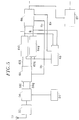
- FIG. 1 The principle diagram for CDMA modulation and demodulation is illustrated in FIG. 1 attached.
- This schematic diagram is voluntarily simplified, in particular there does not appear there the stages RF (radiofrequency) which make it possible, on transmission, to transpose and transmit the signal in the allocated frequency band, and at reception, to recover the signal in the allocated frequency band and transpose it to the base band where it will be processed.
- This figure shows, on the one hand, a spectrum spreading circuit 20 used for transmission and, on the other hand, a suitable filtering circuit 30, used for reception.
- the spread spectrum circuit 20 used for transmission receives information consisting of a series of binary symbols denoted a (k), where k is an index marking the rank of the symbol. These symbols can be received directly from an information source, where, as illustrated in FIG. 1, from a corrector coding circuit 10, which receives the raw information on its input 12 and delivers the protected information on its output 14.
- the frequency information symbols is noted Hs.
- the spread spectrum circuit 20 first comprises a spread sequence generator 22.
- This sequence is formed by a series of binary elements called "chips".
- This sequence is generally pseudo-random.
- the chips are noted ⁇ (n), where n denotes the rank of the chip in the sequence. This rank runs from 0 to N-1 for the same sequence.
- Each information symbol a (k) is multiplied by all the chips of the sequence ⁇ (n) in a multiplier 24. At the output of this multiplier, there is therefore a signal consisting of N pulses of width Tc. With the previous notations, the following of these signals can be noted: ............................ a (k-1). ⁇ (N-1), a (k) . ⁇ (0), a (k) . ⁇ (1), a (k) . ⁇ (2), ..., a (k) . ⁇ (N- 1), a (k + 1) . ⁇ (0), ...
- Such a signal has a bit rate, expressed in chips per second, N times greater than the bit rate in information symbols.
- the spectrum has therefore been spread out in an N ratio.
- the spreading circuit 20 is completed by a filter 26 which is of the low-pass filter type.
- the complete transmitter also comprises other means which have not been shown because they are well known to those skilled in the art, such as for example a local oscillator for generating a carrier, a modulation circuit for this carrier, transmitting antenna, etc.
- the circuit 30 comprises, first of all, a low-pass filter 32, analogous to the filter 26 used on transmission, and a filter 36 adapted to the spreading sequence used on transmission. More precisely, the impulse response of the receiver filter is the time reversal of the pseudo-random sequence used in the transmitter.
- the matched filter 36 performs a convolution operation on the signal delivered by the first filter 32. The flow of pulses at the input of the matched filter 36 carrying out the convolution is equal to the bit rate Hc of the chips, but, after convolution, this flow falls to Hc / N or Hs.
- a circuit 40 decides the value of the information received as a function of the value of the convolution signal. The information is then restored on the general output 42.
- the information transmitted can be ordinary binary information, but it is most often information resulting from a prior operation known as differential coding.
- the symbols a (k) are obtained by a preliminary differential encoder, composed, for example, of a logic gate of the exclusive OR type and of a delay circuit, the gate combining a current bit with the bit which precedes. The symbols thus coded are then multiplied by the pseudo-random sequence which has been discussed.
- the modulation of the carrier it can be of any known type, but it is often preferred to use phase modulation, in particular phase modulation with two states, called MDP2.
- MDP2 phase modulation with two states
- the receiver it suffices to compare the phase of the current symbol with the phase of the previous symbol. The receiver therefore does not have to estimate the phase of the symbols, but only the phase difference between two successive symbols. Hence the "differential" nature of the process.
- Figure 2 illustrates the operation of the system by schematically representing some signals appearing in the chain.
- Binary information is shown on line (a). It is a series of binary symbols of period Ts, in this case the series +1, -1, -1, +1, -1.
- Line (b) illustrates the spreading sequence S formed of N chips, in this case 110100 (naturally, in practice, the number N is much greater than 6).
- Line (c) shows the result of the multiplication of the information signal of line (a) by the sequence S of line (b).
- the correlation signal delivered by the filter to the spreading sequence is represented on line (d). Correlation peaks appear in a background of noise, the sign of which allows the patterns + S and -S to be found. A decision can then be taken to restore the original information (line e).
- Optimal reception then consists in recognizing, in the signal received, the patterns: a1S (t-t1) + a2S (t-t2) + a3S (t-t3) + a4S (t-t4)
- the optimal receiver of FIG. 1 is then completed by a filtering adapted to the impulse response h (t) of the channel.
- the filtering adapted to the impulse response of the channel realizes a recombination of all the existing paths. This operation is partially performed in conventional rake receivers, [1], [3], which combine a limited number of paths.
- the filtering adapted to the received pulse being done at the bit rate of the chips, so that the receiver achieves the best possible performance with a given transmission channel, this bit rate must be high enough.
- this bit rate must be high enough.
- the existing routes can only be taken into account with a chip speed greater than 5 Mchips / s.
- Spread spectrum modulation is precisely a technique which makes it possible to discriminate the different paths constituting the transmission channel.
- the recombination of these paths provides very significant performance gains compared to a transmission which would have undergone an ordinary channel (known as Rayleigh) as will be seen below with reference to FIG. 7.
- the object of the invention is precisely to remedy these drawbacks.
- the invention proposes a demodulation method, one of the essential characteristics of which is to implement an asynchronous sampling of frequency twice the chip frequency, that is to say at the frequency 2Hc.
- a conventional optimal reception requires that we combine samples taken exactly at times t1, t2, t3, ...
- an asynchronous sampling at the rate of the chips, that is to say at the frequency Hc can lead to missing one, two, or even all the received paths, if the sampling instants do not exactly coincide with the instants t1, t2, t3. ..
- an asynchronous sampling at double rhythm that is to say twice the frequency of the chips (2Hc)
- 2Hc twice the frequency of the chips
- This quantity U (k, i) is used to make the decision on the binary value of the information received. This decision is made by comparing the quantity obtained to a threshold of zero value, as is customary in MDP2. This quantity can also be kept in analog form for a possible protection treatment against transmission errors.
- the method of the invention can also be implemented by limiting the calculation of the decision sample to only significant samples.
- a threshold can be used on the amplitude of the samples received. This threshold can be adjusted from the automatic gain control signal, which keeps the power of the demodulated signal at a constant level. This device is found in all transmitters / receivers for radio transmission, and it is also necessary for the proper functioning of a CDMA receiver. Full demodulation is then applied only to samples whose amplitude exceeds the threshold. This this procedure eliminates a number of noise samples.
- FIG. 4 shows the impulse response of the radio mobile channel as it appears at the output of the filter adapted to the spreading sequence (that is to say at the output of the filter 36 in the diagram of FIG. 1).
- These responses have a width at the base of the peaks equal to 2Tc but these peaks are narrow and, by taking a single sample every Tc seconds, it is very possible not to sample the signal correctly.
- the samples are therefore taken at the rate of two per chip. This cadence corresponds to an oversampling of the signal and makes it possible not to miss a journey.
- the advantage of this oversampling is that it does not require perfect location of each path as is the case in conventional rake receivers.
- the circuit 56 delivers two analog signals, traditionally identified by letters I and Q, which are the signals representing the parts of the signal received respectively in phase and in quadrature of phase with the signal produced by the local oscillator 54. These two signals, in phase and in quadrature, are delivered on two connections 58I , 58Q. This whole part of the receiver is classic. The signals are then sampled at the frequency 2Hc and filtered in the circuit 60. This digital filtering is adapted to the chip pulse form used for transmission in the filter 26 of FIG. 1.
- the circuit 60 therefore delivers , on two outputs 62I and 62Q, sequences of 2N samples per period Ts. These samples are then the subject of a filtering adapted to the spreading sequence used on transmission in two filters 64I and 64Q, which deliver two sampled signals which will be noted later, more simply, I and Q. These two signals are applied to a demodulator circuit 66, the output of which is connected to a decision circuit 67. Furthermore, the signals I and Q are sent to a synchronization circuit 68, which delivers both the clock Hc relating to the chips , which allows sampling in the circuit 60 and processing in the demodulator 66, and the clock Hs relating to the information symbols.
- FIG. 6 shows the architecture of the demodulator 66, which makes it possible to calculate the quantities previously defined.
- This demodulator firstly comprises a circuit 70 for calculating products of the form Z (k, i) .Z * (k-1, i) where Z (k, i) is a complex sample of ranks k and i and Z * (k-1, i) the complex conjugate sample of previous rank in the order k of the sequences but of the same rank i within a sequence.
- circuit 70 directly receives samples I and Q of rows k and i, which corresponds to Z (k, i), and samples I (k-1, i) and Q (k-1 , i) delayed by the duration Ts, that is to say delayed by 2N samples. These delayed samples are delivered by two delay circuits 72I, 72Q.
- the circuit 70 having formed the product Z (k, 1) .Z * (k-1, i), it takes the real part, ie U (k, i).
- a circuit 74 receives this signal and forms a weighted sum using weighting coefficients P (k, i) and this in a window going from rank M to rank P, ie:
- the circuit shown also comprises a circuit 76 which receives I and Q and calculates the square of Z (k, i). It also includes taken by a circuit 78 which calculates a quantity A (k, i) which is an average defined by:
- FIG. 7 illustrates the performance of the method of the invention. This figure represents the probability of error as a function of the level of the signal expressed in decibels, for several bit rates.
- the curves shown correspond to the GSM-TU channel with six paths except curve 60 which represents a RAYLEIGH channel.
- Curves 61, 62, 63 are the curves obtained with chip rates of 1, 2 and 4 Mchips / s respectively.
- Curve 64 is the ideal curve corresponding to a rake receiver with six branches, comprising six demodulators with parallel correlation, perfectly synchronized. This reference curve supposes ideal spreading sequences (auto-orthogonal) and cannot therefore be reached in a Qualcomm type system. It does not depend on the bit rate but implicitly assumes that this rate is high enough for the different paths to be separated (of the order of 4 to 5 Mchips / s).
- FIG. 7 clearly shows the influence of the bit rate on the performance of the digital integral differential demodulator.
- the chip pulses must have a duration of the order of the smallest delay separating two successive paths so that the demodulator can recombine the paths.
- Figure 7 shows above all that the digital integral differential demodulator provides performances very close to the ideal.
- the residual offset can be explained by the autocorrelation noise, insofar as the sequences used are not auto-orthogonal but simply pseudo-random, as in the Qualcomm system.
Abstract
Description
La présente invention a pour objet un procédé de démodulation différentielle numérique. Elle trouve une application dans les systèmes de transmission dits à accès multiple à répartition par les codes, ou AMRC en abrégé. Une telle technique est utilisée dans les systèmes radiomobiles.The present invention relates to a digital differential demodulation method. It finds application in so-called code division multiple access transmission systems, or CDMA for short. Such a technique is used in radio mobile systems.
L'exposé de l'état de la technique qui va suivre renvoie à huit documents dont les références sont données en fin de description.The description of the state of the art which follows refers to eight documents, the references of which are given at the end of the description.
L'accès multiple à répartition par les codes, en tant que technique de partage du canal radioélectrique, est souvent envisagé comme base de définition des futurs systèmes radiomobiles de troisième génération. Elle est également utilisée dans certains systèmes actuels de télécommunications avec les mobiles terrestres ou par satellites [1]. Elle permet l'occupation simultanée d'un même canal radio par les signaux émis par plusieurs ou vers plusieurs terminaux mobiles. Ce type de cohabitation propre à l'AMRC n'est rendu possible que grâce à l'emploi d'une modulation à étalement de spectre.Code-division multiple access, as a technique for sharing the radio channel, is often considered as the basis for defining future third-generation radio mobile systems. It is also used in some current telecommunications systems with land mobiles or satellites [1]. It allows simultaneous occupation of the same radio channel by signals transmitted by several or to several mobile terminals. This type of cohabitation specific to CDMA is only made possible by the use of spread spectrum modulation.
Dans la modulation à étalement de spectre, le signal émis occupe une bande de fréquence beaucoup plus large que la bande nécessaire à une transmission utilisant une modulation classique [6] . Deux méthodes d'étalement existent : l'étalement par saut de fréquence et l'étalement par séquence directe [6]. Le facteur d'étalement, qui est le rapport de la bande occupée au débit d'information transmis, est un paramètre important. Dans le système cité en référence [1], il est de 128.In spread spectrum modulation, the transmitted signal occupies a much wider frequency band than the band necessary for transmission. using conventional modulation [6]. Two spreading methods exist: spreading by frequency hopping and spreading by direct sequence [6]. The spreading factor, which is the ratio of the occupied band to the transmitted information rate, is an important parameter. In the system cited in reference [1], it is 128.
La technique de modulation à étalement de spectre constitue une technique d'accès particulièrement souple. Il est en effet possible de transmettre des signaux simultanément dans la même bande fréquence sans aucune coordination. En outre, dans le domaine radiomobile, l'AMRC suscite un intérêt tout particulier dans la mesure où il offre l'opportunité d'un traitement original des trajets multiples engendrés par la propagation.The spread spectrum modulation technique is a particularly flexible access technique. It is indeed possible to transmit signals simultaneously in the same frequency band without any coordination. In addition, in the radiomobile field, the AMRC arouses a very particular interest insofar as it offers the opportunity of an original treatment of the multiple paths generated by the propagation.
Le schéma de principe de la modulation et de la démodulation AMRC est illustré sur la figure 1 annexée. Ce schéma de principe est volontairement simplifié, n'y figurent pas notamment les étages RF (radiofréquence) qui permettent, à l'émission, de transposer et d'émettre le signal dans la bande de fréquence allouée, et à la réception, de récupérer le signal dans la bande de fréquence allouée et de le transposer en bande de base où il sera traité. Sur cette figure, on voit, d'une part, un circuit d'étalement de spectre 20 utilisé à l'émission et, d'autre part, un circuit de filtrage adapté 30, utilisé à la réception. Le circuit d'étalement de spectre 20 utilisé à l'émission reçoit des informations constituées par une suite de symboles binaires notés a(k), où k est un indice marquant le rang du symbole. Ces symboles peuvent être reçus directement d'une source d'informations, où, comme illustré sur la figure 1, d'un circuit de codage correcteur 10, qui reçoit l'information brute sur son entrée 12 et délivre l'information protégée sur sa sortie 14. La fréquence des symboles d'information est notée Hs.The principle diagram for CDMA modulation and demodulation is illustrated in FIG. 1 attached. This schematic diagram is voluntarily simplified, in particular there does not appear there the stages RF (radiofrequency) which make it possible, on transmission, to transpose and transmit the signal in the allocated frequency band, and at reception, to recover the signal in the allocated frequency band and transpose it to the base band where it will be processed. This figure shows, on the one hand, a
Le circuit d'étalement de spectre 20 comprend d'abord un générateur de séquence d'étalement 22. Cette séquence est formée d'une suite d'éléments binaires appelés "chips". Cette séquence est généralement pseudo-aléatoire. La fréquence des chips est notée Hc. Elle est N fois plus grande que la fréquence Hs des symboles d'information (Hc=NHs). Autrement dit, la période des chips, notée Tc, est N fois plus petite que la période des symboles (Tc=Ts/N). Les chips sont notés α(n), où n désigne le rang du chip dans la séquence. Ce rang court de 0 à N-1 pour une même séquence.The
Chaque symbole d'information a(k) est multiplié par tous les chips de la séquence α(n) dans un multiplieur 24. A la sortie de ce multiplieur, on trouve donc un signal constitué de N impulsions de largeur Tc. Avec les notations précédentes, la suite de ces signaux peut être notée :
............................a(k-1). α(N-1), a(k).α(0), a(k).α(1), a(k).α(2), ..., a(k).α(N-1), a(k+1).α(0), ...Each information symbol a (k) is multiplied by all the chips of the sequence α (n) in a
............................ a (k-1). α (N-1), a (k) .α (0), a (k) .α (1), a (k) .α (2), ..., a (k) .α (N- 1), a (k + 1) .α (0), ...
Un tel signal a un débit, exprimé en chips par seconde, N fois plus grand que le débit en symboles d'information. Le spectre a donc bien été étalé dans un rapport N.Such a signal has a bit rate, expressed in chips per second, N times greater than the bit rate in information symbols. The spectrum has therefore been spread out in an N ratio.
Le circuit d'étalement 20 se complète par un filtre 26 qui est du type filtre passe-bas.The spreading
L'émetteur complet comprend encore d'autres moyens qui n'ont pas été représentés parce qu'ils sont bien connus de l'homme de l'art, comme par exemple un oscillateur local pour engendrer une porteuse, un circuit de modulation de cette porteuse, une antenne d'émission, etc...The complete transmitter also comprises other means which have not been shown because they are well known to those skilled in the art, such as for example a local oscillator for generating a carrier, a modulation circuit for this carrier, transmitting antenna, etc.
Côté réception, le circuit 30 comprend, tout d'abord, un filtre passe-bas 32, analogue au filtre 26 utilisé à l'émission, et un filtre 36 adapté à la séquence d'étalement utilisée à l'émission. Plus précisément, la réponse impulsionnelle du filtre du récepteur est la renversée dans le temps de la séquence pseudo-aléatoire utilisée dans l'émetteur. En d'autres termes, le filtre adapté 36 effectue une opération de convolution sur le signal délivré par le premier filtre 32. Le débit des impulsions à l'entrée du filtre adapté 36 réalisant la convolution est égal au débit Hc des chips, mais, après convolution, ce débit tombe à Hc/N soit Hs.On the reception side, the
Un circuit 40 décide de la valeur de l'information reçue en fonction de la valeur du signal de convolution. L'information est alors restituée sur la sortie générale 42.A
Dans un tel système, les informations transmises peuvent être des informations binaires ordinaires, mais elles sont le plus souvent des informations résultant d'une opération préalable dite de codage différentielle. Dans ce cas, les symboles a(k) sont obtenus par un codeur différentiel préliminaire, composé, par exemple, d'une porte logique de type OU exclusif et d'un circuit à retard, la porte combinant un bit courant avec le bit qui précède. Les symboles ainsi codés sont ensuite multipliés par la séquence pseudo-aléatoire dont il a été question.In such a system, the information transmitted can be ordinary binary information, but it is most often information resulting from a prior operation known as differential coding. In this case, the symbols a (k) are obtained by a preliminary differential encoder, composed, for example, of a logic gate of the exclusive OR type and of a delay circuit, the gate combining a current bit with the bit which precedes. The symbols thus coded are then multiplied by the pseudo-random sequence which has been discussed.
Quant à la modulation de la porteuse, elle peut être de tout type connu, mais on préfère souvent utiliser une modulation de phase, notamment la modulation de phase à deux états, dite MDP2. Dans le récepteur, il suffit de comparer la phase du symbole en cours avec la phase du symbole précédent. Le récepteur n'a donc pas à estimer la phase des symboles, mais seulement la différence de phase entre deux symboles successifs. D'où le caractère "différentiel" du procédé.As for the modulation of the carrier, it can be of any known type, but it is often preferred to use phase modulation, in particular phase modulation with two states, called MDP2. In the receiver, it suffices to compare the phase of the current symbol with the phase of the previous symbol. The receiver therefore does not have to estimate the phase of the symbols, but only the phase difference between two successive symbols. Hence the "differential" nature of the process.
La figure 2 permet d'illustrer le fonctionnement du système en représentant schématiquement quelques signaux apparaissant dans la chaîne.Figure 2 illustrates the operation of the system by schematically representing some signals appearing in the chain.
L'information binaire est représentée sur la ligne (a). Il s'agit d'une suite de symboles binaires de période Ts, en l'occurrence la suite +1, -1, -1, +1, -1. La ligne (b) illustre la séquence d'étalement S formée de N chips, en l'occurrence 110100 (naturellement, en pratique, le nombre N est bien supérieur à 6). La ligne (c) montre le résultat de la multiplication du signal d'information de la ligne (a) par la séquence S de la ligne (b). On obtient une suite de motifs +S, -S, -S, +S, -S. Le signal de corrélation délivré par le filtre à la séquence d'étalement est représenté sur la ligne (d). Apparaissent, dans un fond de bruit, des pics de corrélation dont le signe permet de retrouver les motifs +S et -S. Une décision peut alors être prise pour restituer l'information d'origine (ligne e).Binary information is shown on line (a). It is a series of binary symbols of period Ts, in this case the series +1, -1, -1, +1, -1. Line (b) illustrates the spreading sequence S formed of N chips, in this case 110100 (naturally, in practice, the number N is much greater than 6). Line (c) shows the result of the multiplication of the information signal of line (a) by the sequence S of line (b). We obtain a sequence of patterns + S, -S, -S, + S, -S. The correlation signal delivered by the filter to the spreading sequence is represented on line (d). Correlation peaks appear in a background of noise, the sign of which allows the patterns + S and -S to be found. A decision can then be taken to restore the original information (line e).
Les schémas de la figure 2 sont, en fait, assez théoriques car, dans la réalité, le signal radioélectrique se propage de manière complexe entre l'émetteur et le récepteur en suivant plusieurs trajets différents [2],[3],[8]. Le signal reçu se présente au récepteur à des instants décalés. La réponse impulsionnelle d'un canal radiomobile ne se présente donc pas sous forme d'un pic localisé dans le temps, mais plutôt sous forme d'une série de raies d'amplitudes diverses, comme représenté sur la figure 3 annexée. On voit ainsi, sur cette figure, quatre réponses différentes situées aux instants t1, t2, t3 et t4, avec quatre amplitudes différentes a1, a2, a3 et a4.The diagrams in Figure 2 are, in fact, quite theoretical because, in reality, the radio signal propagates in a complex way between the transmitter and the receiver by following several different paths [2], [3], [8] . The received signal is presented to the receiver at offset times. The impulse response of a radio mobile channel is therefore not in the form of a peak localized in time, but rather in the form of a series of lines of various amplitudes, as shown in Figure 3 attached. We thus see, in this figure, four different responses located at times t1, t2, t3 and t4, with four different amplitudes a1, a2, a3 and a4.
La réception optimale consiste alors à reconnaître, dans le signal reçu, les motifs :![]()
![]()
Pratiquement, cela veut dire que le récepteur effectue la corrélation glissante avec la séquence S et doit recombiner les différents pics obtenus pour chacun des trajets existants. Comme il existe un problème dans l'estimation des trajets, c'est-à-dire dans la connaissance des paramètres (a1,t1), ..., (a4,t4), on peut se servir d'un signal pilote (signal spécifique), comme par exemple dans les systèmes Qualcomm, [1], et Globalstar.In practice, this means that the receiver performs the sliding correlation with the sequence S and must recombine the different peaks obtained for each of the existing paths. As there is a problem in the estimation of the paths, that is to say in the knowledge of the parameters (a1, t1), ..., (a4, t4), we can use a pilot signal ( specific signal), as for example in the Qualcomm, [1], and Globalstar systems.
Le récepteur optimal de la figure 1 est alors complété par un filtrage adapté à la réponse impulsionnelle h(t) du canal. D'un point de vue mathématique, le filtrage adapté à la réponse impulsionnelle du canal réalise une recombinaison de tous les trajets existant. Cette opération est partiellement réalisée dans les récepteurs en râteau classique, ("Rake Receiver"), [1],[3], qui combinent un nombre limité de trajets.The optimal receiver of FIG. 1 is then completed by a filtering adapted to the impulse response h (t) of the channel. From a mathematical point of view, the filtering adapted to the impulse response of the channel realizes a recombination of all the existing paths. This operation is partially performed in conventional rake receivers, [1], [3], which combine a limited number of paths.
Le filtrage adapté à l'impulsion reçue se faisant au débit des chips, pour que le récepteur atteigne la meilleure performance possible avec un canal de transmission donné, il faut que ce débit soit assez élevé. Par exemple, avec le canal urbain de type GSM-TU, [8], les trajets existants ne peuvent être tous pris en compte qu'avec un débit chip supérieur à 5 Mchips/s.The filtering adapted to the received pulse being done at the bit rate of the chips, so that the receiver achieves the best possible performance with a given transmission channel, this bit rate must be high enough. For example, with the GSM-TU type urban channel, [8], the existing routes can only be taken into account with a chip speed greater than 5 Mchips / s.
La modulation à étalement de spectre est justement une technique qui permet de discriminer les différents trajets constituant le canal de transmission. La recombinaison de ces trajets procure des gains de performance très appréciables par rapport à une transmission qui aurait subi un canal ordinaire (dit de Rayleigh) comme on le verra plus loin à propos de la figure 7.Spread spectrum modulation is precisely a technique which makes it possible to discriminate the different paths constituting the transmission channel. The recombination of these paths provides very significant performance gains compared to a transmission which would have undergone an ordinary channel (known as Rayleigh) as will be seen below with reference to FIG. 7.
Bien que donnant satisfaction à certains égards, toutes ces techniques ne sont pas pour autant dénuées d'inconvénients. En particulier, elles sont très complexes de mise en oeuvre. Par exemple, dans le système Qualcomm, norme IS-95, il existe un démodulateur par trajet reçu. La norme préconise de mettre en oeuvre cinq démodulateurs, trois pour démoduler les principaux trajets et deux supplémentaires pour gérer l'existence des trajets, notamment leurs apparitions et disparitions. Le débit de transmission de chips de 1 Mbit/s est d'ailleurs adapté à ce nombre de démodulateurs. Avec des débits de chips beaucoup plus importants, nécessaires pour transmettre des services à débits plus élevés, le nombre potentiel de trajets que le récepteur pourra discriminer peut être très grand.Although satisfactory in certain respects, all of these techniques are not without their drawbacks. In particular, they are very complex to implement. For example, in the Qualcomm system, IS-95 standard, there is one demodulator per received path. The standard recommends using five demodulators, three to demodulate the main routes and two additional to manage the existence of the routes, in particular their appearance and disappearance. The chip transmission rate of 1 Mbit / s is moreover adapted to this number of demodulators. With much higher chip speeds, necessary for transmit services at higher rates, the potential number of paths that the receiver can discriminate can be very large.
Le but de l'invention est justement de remédier à ces inconvénients.The object of the invention is precisely to remedy these drawbacks.
A cette fin, l'invention propose un procédé de démodulation dont l'une des caractéristiques essentielles est de mettre en oeuvre un échantillonnage asynchrone de fréquence double de la fréquence chips, c'est-à-dire à la fréquence 2Hc. En effet, et comme le montrait la figure 3, une réception optimale classique nécessite que l'on combine des échantillons pris exactement aux instants t1, t2, t3, ... Mais, comme on le comprendra mieux par la suite, un échantillonnage asynchrone au rythme des chips, c'est-à-dire à la fréquence Hc, peut conduire à rater un, deux, voire tous les trajets reçus, si les instants d'échantillonnage ne coïncident pas exactement avec les instants t1, t2, t3 ...To this end, the invention proposes a demodulation method, one of the essential characteristics of which is to implement an asynchronous sampling of frequency twice the chip frequency, that is to say at the frequency 2Hc. Indeed, and as shown in Figure 3, a conventional optimal reception requires that we combine samples taken exactly at times t1, t2, t3, ... But, as will be better understood below, an asynchronous sampling at the rate of the chips, that is to say at the frequency Hc, can lead to missing one, two, or even all the received paths, if the sampling instants do not exactly coincide with the instants t1, t2, t3. ..
Selon la présente invention, on met en oeuvre un échantillonnage asynchrone au rythme double, c'est-à-dire à deux fois la fréquence des chips (2Hc). Si l'on n'échantillonne pas à l'instant optimal t1, t2 ou t3, on dispose tout de même de deux échantillons du même trajet et l'on ne peut plus rater aucun trajet. Les inventeurs ont vérifié que, pratiquement, la recombinaison de ces échantillons apporte la même information que l'échantillon pris à l'instant optimal, et ceci bien que les échantillons de bruit correspondants soient corrélés. Cette propriété ne se vérifie plus pour un nombre d'échantillons supérieur. En effet, avec un nombre plus grand d'échantillons, on constate que les performances se dégradent.According to the present invention, an asynchronous sampling at double rhythm, that is to say twice the frequency of the chips (2Hc), is implemented. If we do not sample at the optimal time t1, t2 or t3, we still have two samples of the same path and we can no longer miss any path. The inventors have verified that, practically, the recombination of these samples provides the same information as the sample taken at the optimal time, and this although the corresponding noise samples are correlated. This property is no longer checked for a higher number of samples. In fact, with a larger number of samples, it can be seen that the performance degrades.
Pour chaque symbole de rang k, au lieu d'obtenir N échantillons Z(k,i) avec i allant de 1 à N, on en obtient donc, selon l'invention, 2N. Autrement dit, l'indice i de 1 à 2N. La démodulation effectuée est encore de type différentiel. Elle est qualifiée d'intégrale par les inventeurs, en ce sens qu'elle tient compte de tous les trajets significatifs reçus. Selon l'invention, on calcule, pour chaque indice i, le produit d'un échantillon Z(k,i), par l'échantillon précédent conjugué, soit Z*(k-1,i) et l'on fait la somme de ces produits sur les 2N échantillons disponibles. Comme les échantillons sont, en fait, des quantités complexes, on calcule la partie réelle de cette somme, soit la quantité :
En l'absence de toute indication sur la réponse impulsionnelle du canal, c'est-à-dire sur l'étalement et l'amplitude des trajets, il est toutefois possible de se limiter à une fenêtre temporelle plus étroite que la durée d'un symbole transmis. En effet, chaque environnement possède ses caractéristiques de propagation propres. Par exemple, l'étalement des trajets dans les grandes cellules en environnement urbain peut atteindre 5 microsecondes, alors qu'à l'intérieur des bâtiments, il est de l'ordre de quelques dixièmes de microsecondes, [4]. Lors de la mise en place d'un réseau radiomobile, les conditions de propagation font l'objet de mesures précises et la valeur de ce paramètre significatif est bien connue. En conséquence, on limitera le calcul de la grandeur de décision à un intervalle de durée égale à la durée d'étalement correspondant aux conditions d'utilisation du réseau mobile. La démodulation intégrale est alors fondée sur le calcul de la quantité :
Le procédé de l'invention peut être également mis en oeuvre en limitant le calcul de l'échantillon de décision aux seuls échantillons significatifs. A cet usage, on peut utiliser un seuil sur l'amplitude des échantillons reçus. Ce seuil peut être ajusté à partir du signal de contrôle automatique de gain, lequel permet de maintenir la puissance du signal démodulé à un niveau constant. On trouve ce dispositif dans tous les émetteurs/récepteurs pour transmission sur voie radioélectrique, et il est également nécessaire au bon fonctionnement d'un récepteur AMRC. La démodulation intégrale n'est alors appliquée qu'aux seuls échantillons dont l'amplitude dépasse le seuil. Cette façon de procéder permet d'éliminer un certain nombre d'échantillons de bruit.The method of the invention can also be implemented by limiting the calculation of the decision sample to only significant samples. For this purpose, a threshold can be used on the amplitude of the samples received. This threshold can be adjusted from the automatic gain control signal, which keeps the power of the demodulated signal at a constant level. This device is found in all transmitters / receivers for radio transmission, and it is also necessary for the proper functioning of a CDMA receiver. Full demodulation is then applied only to samples whose amplitude exceeds the threshold. This this procedure eliminates a number of noise samples.
Dans une variante particulière, on utilise, pour valider les échantillons, non pas leurs amplitudes instantanées mais leurs amplitudes moyennes, calculées sur K bits, ainsi qu'un seuil adapté à ce traitement particulier.In a particular variant, one uses, to validate the samples, not their instantaneous amplitudes but their average amplitudes, calculated on K bits, as well as a threshold adapted to this particular processing.
Dans la détection du bit de rang k, on propose donc d'utiliser, comme signal de contrôle, les quantités
![]()
![]()
La connaissance de l'amplitude des trajets peut être utilisée dans la quantité à calculer pour prendre la décision. C'est ainsi qu'on améliore les performances avec les deux quantités :

De façon précise, la présente invention a donc pour objet un procédé de démodulation différentielle numérique pour signal obtenu par modulation différentielle à étalement de spectre, ce signal ayant été obtenu à partir d'une information formée d'une suite de symboles a(k) ayant une certaine durée (Ts), chaque symbole a(k) ayant été multiplié par une séquence d'étalement de même durée (Ts) et constituée de N éléments binaires ayant chacun une durée (Tc) qui est N fois plus faible que la durée des symboles (Tc=Ts/N), ce procédé de démodulation différentielle numérique étant caractérisé par le fait qu'il comprend les opérations suivantes :
- a) on suréchantillonne le signal reçu toutes les Tc/2 secondes pour obtenir 2N échantillons numériques complexes pour chaque période Ts du signal, ces 2N échantillons étant notés Z(k,i) où l'indice k est le rang du symbole de période Ts et i le rang de l'échantillon dans la période Ts, l'indice i allant de 1 à 2N,
- b) pour chaque échantillon courant Z(k,i), on considère l'échantillon de même indice i mais situé dans le symbole précédent de rang k-1, soit Z(k-1,i), et l'on forme le complexe conjugué de cet échantillon précédent soit Z*(k-1,i),
- c) on forme le produit de l'échantillon courant par l'échantillon précédent conjugué, soit Z(k,i).Z*(k-1,i),
- d) on forme la somme éventuellement pondérée par des coefficients de pondération P(k,i) de ces produits sur une partie au moins de la période Ts, c'est-à-dire pour le rang i allant d'un entier M supérieur ou égal à 1 jusqu'à un entier P inférieur ou égal à 2N,
- e)on prend la partie réelle U(k,i) de cette somme, ce qui donne un échantillon de décision permettant de restituer l'information correspondant au symbole de rang k.
- a) the signal received is oversampled every Tc / 2 seconds to obtain 2N complex digital samples for each period Ts of the signal, these 2N samples being denoted Z (k, i) where the index k is the rank of the symbol of period Ts and i the rank of the sample in the period Ts, the index i ranging from 1 to 2N,
- b) for each current sample Z (k, i), we consider the sample of the same index i but located in the previous symbol of rank k-1, that is Z (k-1, i), and we form the conjugate complex of this previous sample let Z * (k-1, i),
- c) the product of the current sample is formed by the preceding conjugate sample, ie Z (k, i) .Z * (k-1, i),
- d) the sum possibly weighted by weighting coefficients P (k, i) of these products is formed over at least part of the period Ts, that is to say for the rank i going from an integer M greater or equal to 1 up to an integer P less than or equal to 2N,
- e) the real part U (k, i) of this sum is taken, which gives a decision sample making it possible to restore the information corresponding to the symbol of rank k.
- la figure 1, déjà décrite, est un schéma de principe de la technique à accès multiple à répartition par les codes ;FIG. 1, already described, is a block diagram of the multiple access technique distributed by codes;
- la figure 2, déjà décrite, montre quelques signaux illustrant le principe de cette technique ;FIG. 2, already described, shows some signals illustrating the principle of this technique;
- la figure 3, déjà décrite, montre la réponse impulsionnelle d'un canal radiomobile ;FIG. 3, already described, shows the impulse response of a radio mobile channel;
- la figure 4 montre la sortie du filtre adapté à la séquence d'étalement dans le cas d'un canal radiomobile multitrajet ;FIG. 4 shows the output of the filter adapted to the spreading sequence in the case of a multi-path radio mobile channel;
- la figure 5 est un schéma synoptique d'un récepteur mettant en oeuvre le procédé de démodulation différentielle intégrale numérique selon l'invention ;Figure 5 is a block diagram of a receiver implementing the digital integral differential demodulation method according to the invention;
- la figure 6 est un schéma synoptique proprement dit ;Figure 6 is a block diagram proper;
- la figure 7 montre les performances de la démodulation différentielle intégrale numérique sur un canal à six trajets.FIG. 7 shows the performance of digital integral differential demodulation on a six-path channel.
La figure 4 montre la réponse impulsionnelle du canal radiomobile telle qu'elle apparaît en sortie du filtre adapté à la séquence d'étalement (c'est-à-dire à la sortie du filtre 36 dans le schéma de la figure 1). Ces réponses ont une largeur à la base des pics égale à 2Tc mais ces pics sont étroits et, en prenant un seul échantillon tous les Tc secondes, on peut très bien ne pas échantillonner correctement le signal. Selon une première caractéristique de l'invention, les échantillons sont donc pris au rythme de deux par chip. Cette cadence correspond à un suréchantillonnage du signal et permet de ne pas manquer un trajet. L'avantage de ce suréchantillonnage est qu'il ne demande pas de localisation parfaite de chaque trajet comme c'est le cas dans les récepteurs en râteau classique.FIG. 4 shows the impulse response of the radio mobile channel as it appears at the output of the filter adapted to the spreading sequence (that is to say at the output of the
Cette particularité de suréchantillonnage ne modifie pas naturellement le processus d'émission, mais suppose que le récepteur soit modifié pour le mettre en oeuvre et soit complété par un circuit de calcul des sommes de produits précédemment définis. Un tel récepteur est représenté schématiquement sur la figure 5.This characteristic of oversampling does not naturally modify the transmission process, but supposes that the receiver is modified to implement it and is completed by a circuit for calculating the sums of products previously defined. Such a receiver is shown diagrammatically in FIG. 5.
Il comprend d'abord une antenne de réception 50, un étage de réception radiofréquence 52, un oscillateur local 54 à la fréquence RF ou à une fréquence intermédiaire et un circuit 56 de transposition en bande de base, lequel est relié au circuit 52 et à l'oscillateur local 54. Le circuit 56 délivre deux signaux analogiques, traditionnellement repérés par des lettres I et Q, qui sont les signaux représentant les parties du signal reçu respectivement en phase et en quadrature de phase avec le signal produit par l'oscillateur local 54. Ces deux signaux, en phase et en quadrature, sont délivrés sur deux connexions 58I, 58Q. Toute cette partie du récepteur est classique. Les signaux sont ensuite échantillonnés à la fréquence 2Hc et filtrés dans le circuit 60. Ce filtrage réalisé de façon numérique est adapté à la forme d'impulsion chip utilisée à l'émission dans le filtre 26 de la figure 1. Le circuit 60 délivre donc, sur deux sorties 62I et 62Q, des suites de 2N échantillons par période Ts. Ces échantillons sont ensuite l'objet d'un filtrage adapté à la séquence d'étalement utilisée à l'émission dans deux filtres 64I et 64Q, lesquels délivrent deux signaux échantillonnés qui seront notés par la suite, plus simplement, I et Q. Ces deux signaux sont appliqués à un circuit démodulateur 66 dont la sortie est reliée à un circuit de décision 67. Par ailleurs, les signaux I et Q sont adressés à un circuit de synchronisation 68, qui délivre à la fois l'horloge Hc relative aux chips, qui permet l'échantillonnage dans le circuit 60 et le traitement dans le démodulateur 66, et l'horloge Hs relative aux symboles d'information.It firstly comprises a
La figure 6 montre l'architecture du démodulateur 66, qui permet de calculer les quantités précédemment définies. Ce démodulateur comprend tout d'abord un circuit 70 de calcul de produits de la forme Z(k,i).Z*(k-1,i) où Z(k,i) est un échantillon complexe de rangs k et i et Z*(k-1,i) l'échantillon complexe conjugué de rang précédent dans l'ordre k des séquences mais de même rang i au sein d'une séquence. Pour effectuer ce type de produit, le circuit 70 reçoit directement les échantillons I et Q de rangs k et i, ce qui correspond à Z(k,i), et les échantillons I(k-1,i) et Q(k-1,i) retardés de la durée Ts, c'est-à-dire retardés de 2N échantillons. Ces échantillons retardés sont délivrés par deux circuits à retard 72I, 72Q.FIG. 6 shows the architecture of the
Le circuit 70 ayant formé le produit Z(k,1).Z*(k-1,i), il en prend la partie réelle, soit U(k,i). Un circuit 74 reçoit ce signal et forme une somme pondéré à l'aide de coefficients de pondération P(k,i) et cela dans une fenêtre allant du rang M au rang P soit :
Cette somme constitue l'échantillon de prise de décision qui sera dirigée vers le circuit de prise de décision.This sum constitutes the decision-making sample which will be directed to the decision-making circuit.
Le circuit représenté comprend en outre un circuit 76 qui reçoit I et Q et calcule le carré de Z(k,i). Il comprend encore pris par un circuit 78 qui calcule une quantité A(k,i) qui est une moyenne définie par :
Un circuit 80 détermine la valeur maximale prise par A(k,i) quand le rang i varie, soit S(k)=MaxA(k,i). Le circuit 80 prend une fraction sS(k) de cette valeur, ce qui constitue un seuil T(k).A
Un circuit 82 calcule ensuite des coefficients de pondération P(k,i) de la manière suivante :
- si la moyenne A(k,i) est inférieure au seuil T(k), le coefficient de pondération P(k,i) est pris égal à 0 ; autrement dit, les échantillons qui n'ont pas franchi le seuil ne sont pas pris en compte ;
- si la moyenne A(k,i) est supérieure ou égale au seuil T(k), alors le coefficient de pondération est pris égal à 1 (c'est-à-dire qu'en fait il n'y a pas de pondération) ou est pris égal à A(k,i), ou à A2(k,i).
- if the mean A (k, i) is less than the threshold T (k), the weighting coefficient P (k, i) is taken equal to 0; in other words, samples which have not crossed the threshold are not taken into account;
- if the mean A (k, i) is greater than or equal to the threshold T (k), then the weighting coefficient is taken equal to 1 (i.e. in fact there is no weighting ) or is taken equal to A (k, i), or to A 2 (k, i).
La figure 7 illustre les performances du procédé de l'invention. Cette figure représente la probabilité d'erreur en fonction du niveau du signal exprimé en décibels, pour plusieurs débits chips. Les courbes représentées correspondent au canal GSM-TU à six trajets sauf la courbe 60 qui représente un canal de RAYLEIGH. Les courbes 61, 62, 63 sont les courbes obtenues avec des débits chips respectivement de 1, 2 et 4 Mchips/s. La courbe 64 est la courbe idéale correspondant à un récepteur en râteau à six branches, comprenant six démodulateurs à corrélation en parallèle, parfaitement synchronisés. Cette courbe de référence suppose des séquences d'étalement idéales (auto-orthogonales) et ne saurait donc être atteinte dans un système de type Qualcomm. Elle ne dépend pas du débit chips mais suppose implicitement que ce débit est suffisamment élevé pour que les différents trajets puissent être séparés (de l'ordre de 4 à 5 Mchips/s).FIG. 7 illustrates the performance of the method of the invention. This figure represents the probability of error as a function of the level of the signal expressed in decibels, for several bit rates. The curves shown correspond to the GSM-TU channel with six paths except
La figure 7 fait apparaître clairement l'influence du débit chips sur les performances du démodulateur différentiel intégral numérique. Comme il vient d'être expliqué, il faut que les impulsions chips soient d'une durée de l'ordre du plus petit délai séparant deux trajets successifs pour que le démodulateur puisse recombiner les trajets.FIG. 7 clearly shows the influence of the bit rate on the performance of the digital integral differential demodulator. As just explained, the chip pulses must have a duration of the order of the smallest delay separating two successive paths so that the demodulator can recombine the paths.
La figure 7 montre surtout que le démodulateur différentiel intégral numérique fournit des performances très proches de l'idéal. Le décalage résiduel peut être expliqué par le bruit d'autocorrélation, dans la mesure où les séquences utilisées ne sont pas auto-orthogonales mais simplement pseudo-aléatoires, comme dans le système Qualcomm.Figure 7 shows above all that the digital integral differential demodulator provides performances very close to the ideal. The residual offset can be explained by the autocorrelation noise, insofar as the sequences used are not auto-orthogonal but simply pseudo-random, as in the Qualcomm system.
- [1] A. Salmasi, K.S. Gilhousen, "On the System Design Aspects of Code Division Multiple Access (CDMA) Applied to Digital Cellular and Personal Communications Networks", 41st IEEE Vehicular Technology Conference, May 1991, pp. 57-62.[1] A. Salmasi, K.S. Gilhousen, "On the System Design Aspects of Code Division Multiple Access (CDMA) Applied to Digital Cellular and Personal Communications Networks", 41st IEEE Vehicular Technology Conference, May 1991, pp. 57-62.
- [2] W.C. Jakes Jr., "Microwave Mobile Communication", John Wiley, 1974.[2] W.C. Jakes Jr., "Microwave Mobile Communication", John Wiley, 1974.
- [3] G.L. Turin, "Introduction to Spread Spectrum Antimultipath Techniques and their Applications to Urban Digital Radio", Proceedings of the IEEE, vol. 68, n°3, March 1980, pp. 328-353.[3] G.L. Turin, "Introduction to Spread Spectrum Antimultipath Techniques and their Applications to Urban Digital Radio", Proceedings of the IEEE, vol. 68, n ° 3, March 1980, pp. 328-353.
- [4] H. Hashemi, "The Indoor Propagation Channel", Proceedings of the IEEE, vol. 81, July 1993, pp. 943-968.[4] H. Hashemi, "The Indoor Propagation Channel", Proceedings of the IEEE, vol. 81, July 1993, pp. 943-968.
- [5] J.C. Bic, D. Duponteil, J.C. Imbeaux, "Eléments de Communications Numériques", Collection Technique et Scientifique des Télécommunications, Dunod, 1986.[5] J.C. Bic, D. Duponteil, J.C. Imbeaux, "Elements of Digital Communications", Technical and Scientific Collection of Telecommunications, Dunod, 1986.
- [6] M.K. Simon, J.K. Omura, R.A. Scholtz, B.K. Levitt, "Spread Spectrum Communications", Computer Science Press, 1985.[6] M.K. Simon, J.K. Omura, R.A. Scholtz, B.K. Levitt, "Spread Spectrum Communications", Computer Science Press, 1985.
- [7] M. Kaverhad, G.E. Bodeep, "Design and Experimental Results for a Direct-Sequence Spread Spectrum Radio Using Differential Phase-Shift-Keying Modulation for Indoor Wireless Communications", IEEE Journal on Selected Areas in Communications, vol. SAC-5, N°5, June 1987.[7] M. Kaverhad, GE Bodeep, "Design and Experimental Results for a Direct-Sequence Spread Spectrum Radio Using Differential Phase-Shift-Keying Modulation for Indoor Wireless Communications", IEEE Journal on Selected Areas in Communications, vol. SAC-5, N ° 5, June 1987.
- [8] ETSI, "European Digital Cellular Telecommunications System (Phase 2) ; Radio Transmission and Reception, (GSM 05.05)", 1994.[8] ETSI, "European Digital Cellular Telecommunications System (Phase 2); Radio Transmission and Reception, (GSM 05.05)", 1994.
Claims (6)
Applications Claiming Priority (2)
| Application Number | Priority Date | Filing Date | Title |
|---|---|---|---|
| FR9608866 | 1996-07-16 | ||
| FR9608866A FR2751499B1 (en) | 1996-07-16 | 1996-07-16 | DIGITAL DIFFERENTIAL DEMODULATION METHOD |
Publications (3)
| Publication Number | Publication Date |
|---|---|
| EP0820157A2 true EP0820157A2 (en) | 1998-01-21 |
| EP0820157A3 EP0820157A3 (en) | 1998-01-28 |
| EP0820157B1 EP0820157B1 (en) | 2004-10-20 |
Family
ID=9494089
Family Applications (1)
| Application Number | Title | Priority Date | Filing Date |
|---|---|---|---|
| EP97401680A Expired - Lifetime EP0820157B1 (en) | 1996-07-16 | 1997-07-11 | Method for digital differential demodulation |
Country Status (4)
| Country | Link |
|---|---|
| US (1) | US5960045A (en) |
| EP (1) | EP0820157B1 (en) |
| DE (1) | DE69731260T2 (en) |
| FR (1) | FR2751499B1 (en) |
Cited By (2)
| Publication number | Priority date | Publication date | Assignee | Title |
|---|---|---|---|---|
| EP1475900A3 (en) * | 1999-09-10 | 2004-12-15 | Interdigital Technology Corporation | Interference cancellation in a spread sprectrum communication system |
| US6985515B2 (en) | 1999-09-10 | 2006-01-10 | Interdigital Technology Corporation | Interference cancellation in a spread spectrum communication system |
Families Citing this family (9)
| Publication number | Priority date | Publication date | Assignee | Title |
|---|---|---|---|---|
| US6539050B1 (en) | 1997-06-26 | 2003-03-25 | Hughes Electronics Corporation | Method for transmitting wideband signals via a communication system adapted for narrow-band signal transmission |
| US6510147B1 (en) | 1997-07-15 | 2003-01-21 | Hughes Electronics Corporation | Method and apparatus for orthogonally overlaying variable chip rate spread spectrum signals |
| US6396822B1 (en) | 1997-07-15 | 2002-05-28 | Hughes Electronics Corporation | Method and apparatus for encoding data for transmission in a communication system |
| US6185248B1 (en) * | 1998-03-12 | 2001-02-06 | Northrop Grumman Corporation | Wideband digital microwave receiver |
| FR2794586B1 (en) | 1999-06-02 | 2001-08-03 | Commissariat Energie Atomique | PROCESS FOR PROCESSING AN IMPULSE RESPONSE WITH ADAPTIVE THRESHOLD AND CORRESPONDING RECEIVER |
| US20040110508A1 (en) * | 2002-09-20 | 2004-06-10 | Jacobus Haartsen | Methods and electronic devices for wireless ad-hoc network communications using receiver determined channels and transmitted reference signals |
| KR100649678B1 (en) | 2005-07-15 | 2006-11-27 | 삼성전기주식회사 | Multiple differential demodulator using weighting value |
| KR100759514B1 (en) | 2006-07-10 | 2007-09-18 | 삼성전기주식회사 | Demodulator for wpan and mathod thereof |
| US9112754B2 (en) | 2013-10-08 | 2015-08-18 | Freescale Semiconductor, Inc. | Techniques for generating bit log-likelihood ratios in communication systems using differential modulation |
Citations (4)
| Publication number | Priority date | Publication date | Assignee | Title |
|---|---|---|---|---|
| US4969159A (en) * | 1989-03-22 | 1990-11-06 | Harris Corporation | Spread spectrum communication system employing composite spreading codes with matched filter demodulator |
| GB2233860A (en) * | 1989-07-13 | 1991-01-16 | Stc Plc | "Extending the range of radio transmissions" |
| WO1991015912A1 (en) * | 1990-04-09 | 1991-10-17 | Proxim, Inc. | Radio communication system using spread spectrum techniques |
| US5506862A (en) * | 1993-06-25 | 1996-04-09 | Digital Wireless Corp. | Digital implementation of spread spectrum communications system |
Family Cites Families (1)
| Publication number | Priority date | Publication date | Assignee | Title |
|---|---|---|---|---|
| US5754599A (en) * | 1996-01-04 | 1998-05-19 | Motorola, Inc. | Method and apparatus for coherent channel estimation in a communication system |
-
1996
- 1996-07-16 FR FR9608866A patent/FR2751499B1/en not_active Expired - Fee Related
-
1997
- 1997-07-10 US US08/891,031 patent/US5960045A/en not_active Expired - Fee Related
- 1997-07-11 DE DE69731260T patent/DE69731260T2/en not_active Expired - Fee Related
- 1997-07-11 EP EP97401680A patent/EP0820157B1/en not_active Expired - Lifetime
Patent Citations (4)
| Publication number | Priority date | Publication date | Assignee | Title |
|---|---|---|---|---|
| US4969159A (en) * | 1989-03-22 | 1990-11-06 | Harris Corporation | Spread spectrum communication system employing composite spreading codes with matched filter demodulator |
| GB2233860A (en) * | 1989-07-13 | 1991-01-16 | Stc Plc | "Extending the range of radio transmissions" |
| WO1991015912A1 (en) * | 1990-04-09 | 1991-10-17 | Proxim, Inc. | Radio communication system using spread spectrum techniques |
| US5506862A (en) * | 1993-06-25 | 1996-04-09 | Digital Wireless Corp. | Digital implementation of spread spectrum communications system |
Cited By (10)
| Publication number | Priority date | Publication date | Assignee | Title |
|---|---|---|---|---|
| EP1475900A3 (en) * | 1999-09-10 | 2004-12-15 | Interdigital Technology Corporation | Interference cancellation in a spread sprectrum communication system |
| US6983008B2 (en) | 1999-09-10 | 2006-01-03 | Interdigital Technology Corporation | Base station for use in a CDMA communication system using an antenna array |
| US6985515B2 (en) | 1999-09-10 | 2006-01-10 | Interdigital Technology Corporation | Interference cancellation in a spread spectrum communication system |
| US7545846B2 (en) | 1999-09-10 | 2009-06-09 | Interdigital Technology Corporation | Interference cancellation in a spread spectrum communication system |
| US7684469B2 (en) | 1999-09-10 | 2010-03-23 | Interdigital Technology Corporation | Code division multiple access transmission antenna weighting |
| US7813413B2 (en) | 1999-09-10 | 2010-10-12 | Interdigital Technology Corporation | Antenna array communication using spreading codes |
| US7953139B2 (en) | 1999-09-10 | 2011-05-31 | Interdigital Technology Corporation | Interference cancellation in a spread spectrum communication system |
| US9036680B2 (en) | 1999-09-10 | 2015-05-19 | Interdigital Technology Corporation | Interference cancellation in a spread spectrum communication system |
| US9219522B2 (en) | 1999-09-10 | 2015-12-22 | Interdigital Technology Corporation | Code division multiple access transmission antenna weighting |
| US9270327B2 (en) | 1999-09-10 | 2016-02-23 | Interdigital Technology Corporation | Interference cancellation in a spread spectrum communication system |
Also Published As
| Publication number | Publication date |
|---|---|
| FR2751499B1 (en) | 1998-08-28 |
| US5960045A (en) | 1999-09-28 |
| DE69731260T2 (en) | 2005-11-17 |
| DE69731260D1 (en) | 2004-11-25 |
| FR2751499A1 (en) | 1998-01-23 |
| EP0820157A3 (en) | 1998-01-28 |
| EP0820157B1 (en) | 2004-10-20 |
Similar Documents
| Publication | Publication Date | Title |
|---|---|---|
| EP0113487B1 (en) | Method to be used in an echo cancelling arrangement for measuring an echo delay, and arrangement for carrying out this method | |
| FR2642922A1 (en) | DISPERSE SPECTRUM COMMUNICATION DEVICE | |
| FR2774831A1 (en) | ADAPTIVE SIGNAL RECEIVER FOR CULTIVATED PULTIPLE ACCESS COMMUNICATION SYSTEM | |
| EP0630120A1 (en) | Synchronisation method for radio telephone communications with code division multiplex access | |
| FR2737362A1 (en) | PROCEDURE FOR SELECTING THE PROPAGATION DELAYS RETAINED TO RECEIVE MESSAGES TRANSMITTED BY RADIOCOMMUNICATION WITH SPRAY OF SPECTRUM | |
| EP0013343A1 (en) | Process and device to detect a pseudo-random sequence of 0 degree and 180 degree phase changes of the carrier in a data receiver | |
| EP1260071B1 (en) | Method and device for estimating channel propagation | |
| EP0820157B1 (en) | Method for digital differential demodulation | |
| EP0643504A1 (en) | Threshold detector for CDMA system | |
| EP2958245B1 (en) | Uwb receiver with robust tracking of time drift | |
| FR2681488A1 (en) | DISPERSE SPECTRUM COMMUNICATION DEVICE. | |
| EP0629059B1 (en) | Spread spectrum digital transmission system with low frequency pseudorandom coding of the useful information and method for spectrum spreading and compressing used in such a system | |
| WO2000011799A1 (en) | Iterative rake receiver and corresponding reception method | |
| EP0849889B1 (en) | Method of multipath signal reception | |
| FR3093257A1 (en) | ZADOFF-CHU SEQUENCE MODULATION METHOD AND DEVICE | |
| EP1050987B1 (en) | CDMA multiple access method with improved capacity | |
| EP0702467B1 (en) | Digital transmission system synchronizable on initialization sequences | |
| EP1058402B1 (en) | Method for processing an impulse signal with an adaptive threshold and corresponding receiver | |
| FR2691309A1 (en) | Despreading method in reception of a broadband signal | |
| FR2813474A1 (en) | NON-CONSISTENT DP-MOK RECEPTION METHOD WITH MULTIPLE PATH COMBINATION AND CORRESPONDING RECEIVER | |
| FR2770058A1 (en) | METHOD FOR PROCESSING AN INFORMATION TRANSMISSION SIGNAL BY SPECTRUM SPREAD AND CORRESPONDING RECEIVER | |
| EP0497250B1 (en) | Method for detecting an interfering signal for a digital data demodulator and apparatus for the implementation of such a method | |
| WO2000028662A1 (en) | Digital filter with parallel architecture and spread-spectrum signal receiver using same | |
| EP1252722B1 (en) | Cdma radiocommunication method with access codes and corresponding receiver | |
| EP1693969B9 (en) | CDMA signal reception method with parallel interference suppression and its corresponding stage and receiver |
Legal Events
| Date | Code | Title | Description |
|---|---|---|---|
| PUAI | Public reference made under article 153(3) epc to a published international application that has entered the european phase |
Free format text: ORIGINAL CODE: 0009012 |
|
| PUAL | Search report despatched |
Free format text: ORIGINAL CODE: 0009013 |
|
| AK | Designated contracting states |
Kind code of ref document: A2 Designated state(s): AT BE CH DE DK ES FI FR GB GR IE IT LI LU MC NL PT SE |
|
| AK | Designated contracting states |
Kind code of ref document: A3 Designated state(s): AT BE CH DE DK ES FI FR GB GR IE IT LI LU MC NL PT SE |
|
| 17P | Request for examination filed |
Effective date: 19980706 |
|
| RBV | Designated contracting states (corrected) |
Designated state(s): DE GB |
|
| GRAH | Despatch of communication of intention to grant a patent |
Free format text: ORIGINAL CODE: EPIDOS IGRA |
|
| GRAH | Despatch of communication of intention to grant a patent |
Free format text: ORIGINAL CODE: EPIDOS IGRA |
|
| GRAA | (expected) grant |
Free format text: ORIGINAL CODE: 0009210 |
|
| AK | Designated contracting states |
Kind code of ref document: B1 Designated state(s): DE GB |
|
| REG | Reference to a national code |
Ref country code: GB Ref legal event code: FG4D Free format text: NOT ENGLISH |
|
| REF | Corresponds to: |
Ref document number: 69731260 Country of ref document: DE Date of ref document: 20041125 Kind code of ref document: P |
|
| GBT | Gb: translation of ep patent filed (gb section 77(6)(a)/1977) |
Effective date: 20050201 |
|
| PLBE | No opposition filed within time limit |
Free format text: ORIGINAL CODE: 0009261 |
|
| STAA | Information on the status of an ep patent application or granted ep patent |
Free format text: STATUS: NO OPPOSITION FILED WITHIN TIME LIMIT |
|
| 26N | No opposition filed |
Effective date: 20050721 |
|
| PGFP | Annual fee paid to national office [announced via postgrant information from national office to epo] |
Ref country code: DE Payment date: 20080730 Year of fee payment: 12 |
|
| PGFP | Annual fee paid to national office [announced via postgrant information from national office to epo] |
Ref country code: GB Payment date: 20080630 Year of fee payment: 12 |
|
| GBPC | Gb: european patent ceased through non-payment of renewal fee |
Effective date: 20090711 |
|
| PG25 | Lapsed in a contracting state [announced via postgrant information from national office to epo] |
Ref country code: GB Free format text: LAPSE BECAUSE OF NON-PAYMENT OF DUE FEES Effective date: 20090711 |
|
| PG25 | Lapsed in a contracting state [announced via postgrant information from national office to epo] |
Ref country code: DE Free format text: LAPSE BECAUSE OF NON-PAYMENT OF DUE FEES Effective date: 20100202 |