EP0819942A2 - Apparatus for transferring liquid having liquid level sensing function - Google Patents
Apparatus for transferring liquid having liquid level sensing function Download PDFInfo
- Publication number
- EP0819942A2 EP0819942A2 EP97111437A EP97111437A EP0819942A2 EP 0819942 A2 EP0819942 A2 EP 0819942A2 EP 97111437 A EP97111437 A EP 97111437A EP 97111437 A EP97111437 A EP 97111437A EP 0819942 A2 EP0819942 A2 EP 0819942A2
- Authority
- EP
- European Patent Office
- Prior art keywords
- liquid
- probe
- inner tube
- container
- sensing electrode
- Prior art date
- Legal status (The legal status is an assumption and is not a legal conclusion. Google has not performed a legal analysis and makes no representation as to the accuracy of the status listed.)
- Granted
Links
Images


Classifications
-
- G—PHYSICS
- G01—MEASURING; TESTING
- G01N—INVESTIGATING OR ANALYSING MATERIALS BY DETERMINING THEIR CHEMICAL OR PHYSICAL PROPERTIES
- G01N35/00—Automatic analysis not limited to methods or materials provided for in any single one of groups G01N1/00 - G01N33/00; Handling materials therefor
- G01N35/10—Devices for transferring samples or any liquids to, in, or from, the analysis apparatus, e.g. suction devices, injection devices
- G01N35/1009—Characterised by arrangements for controlling the aspiration or dispense of liquids
-
- G—PHYSICS
- G01—MEASURING; TESTING
- G01F—MEASURING VOLUME, VOLUME FLOW, MASS FLOW OR LIQUID LEVEL; METERING BY VOLUME
- G01F23/00—Indicating or measuring liquid level or level of fluent solid material, e.g. indicating in terms of volume or indicating by means of an alarm
- G01F23/22—Indicating or measuring liquid level or level of fluent solid material, e.g. indicating in terms of volume or indicating by means of an alarm by measuring physical variables, other than linear dimensions, pressure or weight, dependent on the level to be measured, e.g. by difference of heat transfer of steam or water
- G01F23/26—Indicating or measuring liquid level or level of fluent solid material, e.g. indicating in terms of volume or indicating by means of an alarm by measuring physical variables, other than linear dimensions, pressure or weight, dependent on the level to be measured, e.g. by difference of heat transfer of steam or water by measuring variations of capacity or inductance of capacitors or inductors arising from the presence of liquid or fluent solid material in the electric or electromagnetic fields
- G01F23/263—Indicating or measuring liquid level or level of fluent solid material, e.g. indicating in terms of volume or indicating by means of an alarm by measuring physical variables, other than linear dimensions, pressure or weight, dependent on the level to be measured, e.g. by difference of heat transfer of steam or water by measuring variations of capacity or inductance of capacitors or inductors arising from the presence of liquid or fluent solid material in the electric or electromagnetic fields by measuring variations in capacitance of capacitors
- G01F23/268—Indicating or measuring liquid level or level of fluent solid material, e.g. indicating in terms of volume or indicating by means of an alarm by measuring physical variables, other than linear dimensions, pressure or weight, dependent on the level to be measured, e.g. by difference of heat transfer of steam or water by measuring variations of capacity or inductance of capacitors or inductors arising from the presence of liquid or fluent solid material in the electric or electromagnetic fields by measuring variations in capacitance of capacitors mounting arrangements of probes
-
- G—PHYSICS
- G01—MEASURING; TESTING
- G01N—INVESTIGATING OR ANALYSING MATERIALS BY DETERMINING THEIR CHEMICAL OR PHYSICAL PROPERTIES
- G01N35/00—Automatic analysis not limited to methods or materials provided for in any single one of groups G01N1/00 - G01N33/00; Handling materials therefor
- G01N35/10—Devices for transferring samples or any liquids to, in, or from, the analysis apparatus, e.g. suction devices, injection devices
- G01N35/1009—Characterised by arrangements for controlling the aspiration or dispense of liquids
- G01N2035/1025—Fluid level sensing
-
- Y—GENERAL TAGGING OF NEW TECHNOLOGICAL DEVELOPMENTS; GENERAL TAGGING OF CROSS-SECTIONAL TECHNOLOGIES SPANNING OVER SEVERAL SECTIONS OF THE IPC; TECHNICAL SUBJECTS COVERED BY FORMER USPC CROSS-REFERENCE ART COLLECTIONS [XRACs] AND DIGESTS
- Y10—TECHNICAL SUBJECTS COVERED BY FORMER USPC
- Y10T—TECHNICAL SUBJECTS COVERED BY FORMER US CLASSIFICATION
- Y10T436/00—Chemistry: analytical and immunological testing
- Y10T436/11—Automated chemical analysis
- Y10T436/119163—Automated chemical analysis with aspirator of claimed structure
Definitions
- the present invention relates to an apparatus for transferring a liquid having a liquid level sensing function, and more particularly relates to an apparatus for transferring a liquid suitable for applying a clinical automatic analyzer for analyzing body fluid samples.
- an automatic analyzer for automatically analyzing biological samples, as a pre-treatment of analysis there is a process in which a sample and a reagent are pipetted and reacted. Further, the reacted reaction solution sometimes needs to be pipetted. It is a necessary condition for accurately performing the measurement of the sample to accurately perform the pipetting work.
- a pipetting probe is dipped in the sample or the reagent to suck the sample or the reagent into the pipetting probe using a sucking means such as a syringe. Then, the probe having pipetted the sample or the reagent is moved down inside a reaction container to discharge the sample or the reagent in the probe into the reaction container by a discharging operation of the syringe. Pure water is generally used as a medium for transmitting the operation of the syringe to the probe, that is, as an in-flow-passage moving fluid.
- the depth of dipping the probe into the sample or the reagent should be minimized.
- the reason is as follows. Since the sample or the reagent is attached onto the outer surface of the probe when the probe is dipped into the sample or the reagent, the sample or the reagent attached onto the surface must be cleaned. However, if the probe is inserted into the sample or the reagent more deeply than a necessary depth, the outer wall of the probe is not sufficiently cleaned and the remaining fluid attached on the probe may become a source of contamination. Further, a large amount of water cleaning the outer wall of the probe is necessary if the probe is inserted into the sample or the reagent more deeply than a necessary depth, which is not preferable from the viewpoint of economy.
- a liquid level sensor of electrostatic capacitance type disclosed, for example, in Japanese Patent Application Laid-Open No. 1-178826 is used.
- the detection of a liquid surface utilizes the fact that the body fluid sample and the reagent are conductive fluids.
- the inside of the vertically movable probe is filled with pure water as an in-flow-passage movable fluid, and the sample is sucked into the probe by operation of the syringe.
- a sample container is placed on a metallic container holder.
- the probe formed of a single tube is used as a one electrode for detecting a liquid surface, and the container holder is used as the other electrode.
- the probe serves as the electrode for detecting liquid surface, and the container holder is grounded.
- An electrostatic capacitance between the electrodes is converted to an electric signal corresponding to the electrostatic capacitance using a converting circuit.
- a detection circuit detects that the probe reaches the liquid surface when the capacitance changes, and the downward movement of the probe is stopped.
- a liquid level sensor using a pipetting probe having two tubes is disclosed in Japanese Patent Application Laid-Open No.7-43369.
- An inner tube is used as an electrode for detecting liquid surface, and an outer tube is used as an electric conductive shield member.
- the outer tube is grounded.
- the top end of the inner tube is positioned at a level lower than the top end of the outer tube so that the inner tube may be brought in contact with a sample to be pipetted.
- An electric insulator insulates between the inner tube and the outer tube.
- the electrostatic capacitance between the pipetting probe and the container holder changes as the probe is moved upward or downward. Such change disturbs the measurement of detecting a liquid surface of a liquid to be pipetted.
- An object of the present invention is to provide an apparatus for transferring a liquid in which a liquid having electric conductivity can be used as a movable fluid applied to a pipetting probe.
- Another object of the present invention is to provide an apparatus for transferring a liquid in which the change of electric capacitance between a pipetting probe and a container holder is extremely small during a period when the pipetting probe is being moved downward until it comes in contact with a liquid surface.
- a further object of the present invention is to provide an apparatus for transferring a liquid having a liquid level sensor in which an electric connection between a movable fluid and a nozzle tip does not occur.
- a probe is constructed so that movable fluid moved in the probe by operation of a pipetting pump is not in contact directly with a liquid level sensing electrode of the probe and is also electrically not connected with the liquid level sensing electrode.
- the probe in accordance with the present invention has an inner tube and the liquid level sensing electrode, and the liquid level sensing electrode has an outer tube. Just before starting sucking operation of a liquid to be pipetted by the probe, the inside of the inner tube is filled with the moving fluid. The liquid level sensing electrode is into contact with the liquid to be pipetted, but the inner tube does not come in contact with the liquid.
- the top end of the liquid level sensing electrode is arranged so as to be positioned at a level lower than the level of the top end of the inner tube, and the inner tube is arranged so that the liquid taken into the probe does not come into contact to the inner tube. Further, the liquid level sensing electrode and the inner tube are electrically insulated between them.
- the inner tube is made of an electrically conductive material, and the inner tube is in the same electric potential with the container holder.
- the apparatus for transferring a liquid comprises an electrically conductive container holder for holding a container containing a liquid to be pipetted, a probe for pipetting part of the liquid in the container, a pipetting pump connected to the probe, the pump being capable of sucking the liquid into the probe by moving the movable fluid in the probe, and a device for outputting a signal detecting the liquid surface of the liquid on the container based on a change in electrostatic capacitance between the container holder and the probe.
- the liquid level sensing electrode has an electrically conductive nozzle tip, and the nozzle tip is detachably connected to the outer tube.
- the liquid level sensing electrode has a hollow compartment for receiving a liquid from a container, and the inner tube is arranged so that the top end of the inner tube is exposed in the hollow compartment.
- the inner tube is made of an electrically conductive material, and the container holder and the inner tube are grounded. Further, there is provided a means for measuring an electric potential between the liquid level sensing electrode and the inner tube in order to check an electric connection between the liquid level sensing electrode and the inner tube.
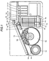
- FIG. 1 is a plan view showing an embodiment of an automatic analyzer to which the present invention is applied.
- FIG. 2A is a schematic view showing the construction of an apparatus for transferring a liquid used in the analyzer of FIG. 1.
- FIG. 2B is an enlarged view of the probe in FIG. 2A.
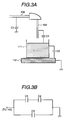
- FIG. 3A is a schematic diagram explaining the distribution of electrostatic capacitance in a conventional liquid surface detecting sensor.
- FIG. 3B is a diagram showing the equivalent circuit for the construction of FIG. 3A.
- FIG. 4A is a schematic diagram explaining the distribution of electrostatic capacitance in a liquid surface detecting sensor to which the present invention is applied.
- FIG. 4B is a diagram showing the equivalent circuit for the construction of FIG. 4A.
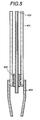
- FIG. 5 is a cross-sectional view showing a modified embodiment of a probe.
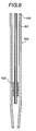
- FIG. 6 is a cross-sectional view showing another modified embodiment of a probe.
- FIG. 7 is a view showing the construction of the main portion of another embodiment of an apparatus for transferring a liquid of which construction of flow passage of moving fluid is modified.
- FIG. 1 is a view showing an example of an automatic analyzer to which an apparatus for transferring a liquid in accordance with the present invention is applied.
- a plurality of sample containers 701 are arranged on a sample disk 702 which can be rotated using a motor. These sample containers 701 are detachably mounted onto the sample disk 702 which forms container holders.
- a plurality of reagent bottles 703 are arranged on a reagent disk 704 which can be rotated using a motor.
- the reagent disk 704 has a plurality of container holders.
- Reaction containers 707 are stored in a reaction position 706.
- a pipetter arm 708 having a probe can be moved from an upper portion of a sample sucking position 709 to an upper portion of a reaction container receiving position 723, and from an upper portion of a reagent sucking position 710 to the upper portion of the reaction container receiving position 723 using a motor, and further can be moved vertically at each of the positions.
- a sipper 711 can be freely moved among an upper portion of a reaction solution sucking position 712, an upper portion of a buffer solution sucking position 713 and an upper portion of an in-flow-cell cleaning liquid sucking position 714 using a motor, and also can be vertically moved at each of the positions.
- the sipper 711 has a function to transfer a reaction solution to a flow cell in a detecting unit 715 through a tube.
- a transferring mechanism 717 for tip and reaction container transfers an unused disposable nozzle tip 105 from a tip storing position 718 to a tip connecting position 720, an unused disposable reaction container 707 from a reaction container storing position 719 to a reaction container receiving position 723, the reaction container 707 added with a sample and a reagent from the reaction container receiving position 723 to the reaction position 706 in a constant temperature bath 705, and further the reaction container 707 after incubation from the reaction position 706 to the reaction solution sucking position 712.
- the analyzer has an apparatus for transferring a liquid as shown in FIG. 2A, and a pipetting probe 100 as shown in FIG. 2B is attached to the pipetter arm 708.
- the probe 100 has an inner tube 102 containing a moving fluid, a liquid level sensing electrode 103 and an electrostatic capacitance shield member 101.
- the sample disk 702, the reagent disk 704, the inner tube 102 and the electrostatic capacitance shield member 101 are grounded. By doing so, the container holders in the disks 702 and 704 are grounded.
- the unused nozzle tip 105 is connected to the outer tube 103A of the probe 100 at the tip connecting position 720 prior to starting sucking operation of a sample and/or a reagent.
- the sipper 711 has a liquid level sensor which has a structure different from that of the liquid level sensor in accordance with the present invention.
- Each of the units is time-controlled to be operated by a controller 108.
- the transferring mechanism 717 for tip and reaction container transfers an unused disposable nozzle tip 105 to the tip connecting position 720 and an unused reaction container 707 to the reaction container receiving position 723.
- the sample disk 702 is rotated so that a sample container 704 containing a sample to be analyzed is positioned at the sample sucking position 709.
- a reagent disk 704 is rotated so that a reagent bottle containing a reagent used for the analysis is positioned at the reagent sucking position 710.
- an unused nozzle tip is connected to the pipetting probe 100 at the upper portion of the tip connecting position 720, and then the pipetter arm 708 is moved to the reagent sucking position.
- the pipetter arm 708 is moved down at the reagent sucking position 710 and the liquid level sensor is actuated to stop the operation of downward movement when the top end of the disposable nozzle tip 105 reaches the liquid surface of the reagent.
- the reagent is sucked in the nozzle tip 105 of the probe 100.
- the pipetter arm 708 is moved upward and to a probe cleaning position 721. As the probe 100 reaches the probe cleaning position 721, cleaning water comes out from a cleaning unit to clean the outer wall of the nozzle tip 105.
- the pipetter arm 708 is moved to the upper portion of the sample sucking position 709 on the sample disk 702.
- the pipetter arm 708 is moved down at the sample sucking position 709 and the liquid level sensor is actuated to stop the operation of downward movement when the disposable tip 105 reaches the liquid surface of the sample.
- the pipetter 708 sucks the sample.
- the pipetter arm 708 is moved upward and moved to the upper portion of the reaction container receiving position 723.
- the pipetter arm 708 is moved downward and stopped at an appropriate level to eject the mixed solution of the sample and the reagent into a reaction container 707.
- the pipetter arm 708 After ejecting the mixed solution, the pipetter arm 708 is moved upward and moved to a tip disposing position 725. At the tip disposing position 725, the nozzle tip 105 detached from the outer tube 103A of the probe 100 is disposed. Then, the transferring mechanism 717 transfers the reaction container 707 containing the mixed solution from the reaction container receiving position 723 to the reaction position 706.
- the sipper 711 After elapsing an appropriate time for reaction, the sipper 711 is moved to the upper portion of the buffer solution sucking position 713. The sipper 711 is moved downward and the liquid detector is actuated to stop operation of downward movement when the top end of the sipper reaches the liquid surface of the buffer solution. Then, the buffer solution is sucked. After that, the top end portion of the sipper 711 is cleaned at a sipper cleaning position 722.
- the transferring mechanism 717 further transfers the reaction container 707 after passing an incubation time from the reaction position 706 to the reaction solution sucking position 712.
- the sipper 711 sucks the reaction solution at the reaction solution sucking position 712. After sucking the reaction solution, the sipper 711 is moved to the buffer solution sucking position 713 to suck the buffer solution.
- the buffer solution and the reaction solution are introduced into a flow cell in the detecting unit 715 through a tube to be measured. Then, the sipper 711 sucks a cleaning liquid at the in-flow-cell cleaning liquid sucking position 714 to clean the inside of the flow cell in the detecting unit 715 through the tube.
- FIG. 2A shows an embodiment of an apparatus for transferring a liquid to which the present invention is applied
- FIG. 2B is a cross-sectional view of a pipetting probe used in FIG. 2A
- the inner tube 102 of the probe 100 is connected to the syringe 107 through a connecting tube 106, and the inside of the inner tube 102 is filled with water supplied from a cleaning water supply tank 121 through a switching valve 120.
- the water in the inner tube 102 of the pipetting probe 100 and the connecting tube 106 is moved inside the flow passage by operation of the syringe 107 serving as a pipetting pump, and functions as a movable fluid necessary for the pipetting operation.
- the pipetting probe 100 has the inner tube 102, the liquid level sensing electrode and the electric conductive shield member 101.
- the probe 100 is fixed to the pipetter arm 708.
- the liquid level sensing electrode 103 has the outer tube 103A coaxial to the inner tube 102 and the disposable nozzle tip 105.
- the outer diameter if the lower end portion of the outer tube 103A is determined so as to be closely engaged with the top portion of the nozzle tip 105.
- the outer tube 103A is electrically connected to one of input terminals of a measuring unit 113 through a lead wire.
- the electrically conductive shield member 101 in the probe 100 is also cylindrical, and therefore the prove has a coaxial triple-tube structure.
- a container 111 such as the sample container 701 or the reagent container 703 is contained in the container holder 112 made of a metal of electrically conductive material.
- the container holder 112 made of a metal of electrically conductive material.
- the electrically conductive shield member 101, the inner tube 102 and the liquid level sensing electrode 103 are made of a metallic conductive material such as stainless steel, and electric insulating members 104A and 104B made of polybuthylene-terephtharate (PBT) or the like electrically insulate between the shield member 101 and the sensing electrode 103 and between the inner tube 102 and the sensing electrode 103, respectively. Further, the shield member 101 and the inner tube 102 are grounded.
- PBT polybuthylene-terephtharate
- a liquid to be pipetted such as a sample, a reagent or a reaction solution of a sample and a reagent is sucked in the nozzle tip 105 forming the sensing electrode 103.
- the nozzle tip 105 is detachable to the outer tube 103A and disposable.
- the nozzle tip 105 is made of an electrically conductive material such as an electrically conductive plastic.
- the electrostatic capacitance between the container holder 112 of the other electrode for detecting liquid surface and the sensing electrode 103 is less affected by an electrostatic capacitance change in the other portions. Furthermore, since the electric conductive shield member 101 exists, it is possible to prevent erroneous operation of the liquid level sensing due to noise from outside caused by a motor 109 and so on.
- the top end of the inner tube 102 is projecting to the top end of the outer tube 103A. That is, the top end of the inner tube 102 is placed at a level lower than the top end of the outer tube 103A.
- the projecting portion of the inner tube 102 is exposed inside the hollow compartment formed by the nozzle tip 105.
- the lower end of an electric insulator member 104B is projected from the outer tube 103 and exposed to the hollow compartment inside the nozzle tip 105. Since the top end of the inner tube 102 is kept a distance from the outer tube 103A by such a construction, electric continuity between the inner tube 102 and the outer tube 103A can be prevented even if water droplets attach to the top end of the inner tube.
- the probe 100 can be vertically moved by a probe vertical moving mechanism 110.
- a container 111 containing a liquid to be pipetted is stored in the container holder 112.
- the container holder 112 is made of a conductive material such as aluminum and grounded.
- the sensing electrode 103 and the container holder 112 are connected to an electrostatic capacitance measuring unit 113 as two electrodes for an electrostatic capacitance type liquid level sensor. Further, a liquid surface judging unit 114 is connected between the electrostatic capacitance measuring unit 113 and a control unit 108.
- the probe 100 connected the nozzle tip 105 is moved downward by the vertical moving mechanism 110 to suck the liquid contained in the container 111.
- the electrostatic capacitance measuring unit 113 measures an electrostatic capacitance between the sensing electrode 103 and the container holder 112 and the corresponding output signal is transferred to the liquid surface judging unit 114.
- the liquid surface judging unit 114 transmits a liquid surface detecting signal to the controller 108.
- the controller 108 stops rotation of the motor 109 to stop downward movement of the probe 100.
- the connecting tube 106 and the inner tube 102 are filled with a movable medium (liquid) such as water or the like, and accordingly sucking of the liquid into the nozzle tip and discharging of the sucked liquid from the nozzle tip 105 are performed by the movable fluid serving as the sucking and discharging medium moving in the flow passage corresponding to operation of the syringe 107.
- the control unit 108 controls vertical movement of the probe 100 and operation of the syringe 107 so that the liquid surface of the liquid sucked in the nozzle tip does not contact to the inner tube 102 and the moving medium inside the inner tube.
- a foreign object detector 115 measures an electric potential between the sensing electrode 103 and the inner tube 102 and recognizes from change in the electric potential that an object (liquid) is attached to the top end of the nozzle tip.
- the foreign object detector 115 it is possible to detect in real time by detecting the change in the electric potential that the outer tube 103A and the inner tube 103 are brought in conduction. Further, in this case, a signal is transmitted from the foreign object detector 115 to an alarm generator 116 to generate an alarm.
- the control unit 108 controls operation of the syringe 107 so as to perform cleaning operation.
- FIG. 3A shows distribution of electrostatic capacitance in the portion of a liquid level sensor employed in a conventional apparatus for transferring a liquid
- FIG. 3B shows the equivalent circuit.
- the reference character C1 indicates an electrostatic capacitance between the sensing electrode 103B and the liquid surface in the container 111
- the reference character C2 indicates an electrostatic capacitance between the container holder 112 (grounded) and the liquid in the container 111
- the reference character C3 indicates an electrostatic capacitance between the movable medium filling the connecting tube 106 and the other grounded positions of the apparatus.
- the movable fluid is pure water
- FIG. 4A shows the distribution of electrostatic capacitance of a liquid level sensor in an apparatus for transferring a liquid to which the present invention is applied
- FIG. 4B shows the equivalent circuit.
- the reference character C1 indicates an electrostatic capacitance between the sensing electrode 103 and the liquid surface in the container 111
- the reference character C2 indicates an electrostatic capacitance between the container holder 112 (grounded) and the liquid in the container 111
- the reference character C4 indicates an electrostatic capacitance between the sensing electrode 103 and the inner tube 102 (grounded).
- the measured electrostatic capacitance is irrespective of the electric conductance of the water in the connecting tube 106 including the flow passage.
- liquid surface can be detected only when the electric conductivity of the moving fluid of water in the connecting tube 106 is lower than 1 ⁇ S/cm.
- FIG. 5 shows a modified embodiment of a pipetting probe used in an apparatus for transferring a liquid in accordance with the present invention.
- This probe 400 is of a coaxial double tube construction of an outer tube 401 and an inner tube 402.
- Each of the outer tube 401 and the inner tube 402 is made of an electrically conductive material, and are electrically insulated by an electric insulator material 403 between them.
- the inner tube 402 is grounded.
- a detachable disposable nozzle tip 404 is connected to near the top end of the probe 400, and liquid is sucked in the inside space portion of the nozzle tip 404.
- the other parts except for the probe 400 and the operation are the same as those in the apparatus of FIG. 2A.
- the construction of the probe of FIG. 5 is simple in a point that the probe does not have the electrically conductive shield member 101 shown in FIG. 2B.
- FIG. 6 shows another modified embodiment of a probe used in an apparatus for transferring a liquid in accordance with the present invention.
- This probe 500 is of a coaxial double tube construction of an outer tube 501 serving as a sensing electrode and an inner tube 502 serving as a movable fluid tube.
- Each of the outer tube 501 and the inner tube 502 is made of an electrically conductive material, and the outer tube 501 and the inner tube 502 are electrically insulated by an electric insulator material 503 between them.
- the inner tube 502 is grounded.
- FIG. 6 shows an example of a probe without using disposable nozzle tip, and the liquid to be pipetted is sucked in the inside space portion formed by the outer tube near the top end portion of the outer tube. In this case, the sucked liquid is not in contact with the inner tube 502.
- the other parts except for the probe 500 and the operation are the same as those in the apparatus of FIG. 2A.
- FIG. 7 shows the main portion of another embodiment of an apparatus for transferring a liquid in accordance with the present invention.
- an outer tube 601 serving as a sensing electrode and an inner tube 602 serving as a moving fluid tube are formed a coaxial state, extended up to near the syringe 107 so as to include a probe 600 and a connecting tube, and a circuit 603 for maintaining an electric potential between the outer tube and the inner tube at a constant is connected between them.
- the electrostatic capacitance between the outer tube 601 and the inner tube 602 can be maintained at a constant, and consequently it is possible to prevent the effect of a change in the electrostatic capacitance on the liquid level sensing.
- a circuit for maintaining electric potential between coaxial tubes constant disclosed in USP5,304,347 may be employ as the circuit 603 for maintaining electric potential constant.
Abstract
Description
Claims (9)
- An apparatus for transferring a liquid comprising a container holder for holding an electric conductive container containing a liquid to be pipetted; a probe for pipetting part of the liquid in the container; a pipetting pump connected to the probe, the pump allowing the liquid to be sucked into the probe by moving a movable fluid in the probe; and a device for outputting a signal of detecting a liquid surface of the liquid in the container based on a change in an electrostatic capacitance between the container holder and the probe; whereinsaid probe comprises an inner tube filled with the moving fluid therein; and a liquid level sensing electrode having an outer tube and being capable of contacting with the liquid to be pipetted;the top end of said liquid level sensing electrode being arranged so as to be positioned at a level lower than the top end of the inner tube, the inner tube being arranged so that the liquid taken into the probe is prevented from coming into contact with the inner tube, said liquid level sensing electrode and the inner tube being electrically insulated therebetween.
- An apparatus for transferring a liquid according to claim 1, whereinsaid liquid level sensing electrode comprises an electrically conductive nozzle tip, and said nozzle tip is detachably connected to the outer tube.
- An apparatus for transferring a liquid according to claim 2, whereinthe nozzle tip forms a hollow compartment for receiving the liquid in the nozzle tip when the nozzle tip is connected to the outer tube, and the top end of the inner tube is projected in said hollow compartment.
- An apparatus for transferring a liquid according to claim 2, whereinsaid inner tube is made of an electrically conductive material, and said container holder and said inner tube are the same in electric potential with each other.
- An apparatus for transferring a liquid according to claim 1, whereinsaid probe has an electrically conductive shield member for covering said outer tube.
- An apparatus for transferring a liquid comprising a container holder for holding an electrically conductive container containing a liquid to be pipetted; a probe for pipetting part of the liquid in the container; a pipetting pump connected to the probe, the pump allowing the liquid to be sucked into the probe by moving a movable fluid in the probe; and a device for outputting a signal of detecting a liquid surface of the liquid in the container based on a change in an electrostatic capacitance between the container holder and the probe; whereinsaid probe comprises an inner tube filled with the movable fluid therein; a liquid level sensing electrode having an outer tube and being capable of coming into contact with the liquid to be pipetted; and an electric insulator member placed between the inner tube and the outer tube;the inner tube being made of an electric conductive material, the inner tube and the container holder being the same in electric potential with each other.
- An apparatus for transferring a liquid according to claim 6, which comprises a means for measuring an electric potential difference between said liquid level sensing electrode and said inner tube in order to check an electric conduction state between said liquid level sensing electrode and said inner tube.
- An apparatus for transferring a liquid according to claim 6, whereinsaid inner tube and said container holder are grounded.
- An apparatus for transferring a liquid according to claim 6, whereinsaid liquid level sensing electrode comprises a hollow compartment for receiving the liquid from said container, and said inner tube is arranged so that the top end of the inner tube is exposed in said hollow compartment.
Applications Claiming Priority (3)
| Application Number | Priority Date | Filing Date | Title |
|---|---|---|---|
| JP190551/96 | 1996-07-19 | ||
| JP19055196 | 1996-07-19 | ||
| JP19055196A JP3158054B2 (en) | 1996-07-19 | 1996-07-19 | Liquid sampling device |
Publications (3)
| Publication Number | Publication Date |
|---|---|
| EP0819942A2 true EP0819942A2 (en) | 1998-01-21 |
| EP0819942A3 EP0819942A3 (en) | 1998-09-23 |
| EP0819942B1 EP0819942B1 (en) | 2001-04-11 |
Family
ID=16259966
Family Applications (1)
| Application Number | Title | Priority Date | Filing Date |
|---|---|---|---|
| EP97111437A Expired - Lifetime EP0819942B1 (en) | 1996-07-19 | 1997-07-07 | Apparatus for transferring liquid having liquid level sensing function |
Country Status (6)
| Country | Link |
|---|---|
| US (1) | US5855851A (en) |
| EP (1) | EP0819942B1 (en) |
| JP (1) | JP3158054B2 (en) |
| AT (1) | ATE200582T1 (en) |
| DE (1) | DE69704522T2 (en) |
| ES (1) | ES2157034T3 (en) |
Cited By (9)
| Publication number | Priority date | Publication date | Assignee | Title |
|---|---|---|---|---|
| NL1012197C2 (en) * | 1999-05-31 | 2000-12-01 | Univ Delft Tech | Device for determining an amount of a liquid. |
| DE20117914U1 (en) * | 2001-11-02 | 2003-03-13 | Evotec Ag | Sample delivery device |
| US8358216B2 (en) | 2009-04-09 | 2013-01-22 | Shenzhen Mindray Bio-Medical Electronics Co., Ltd. | Liquid level detecting device and sample applying system |
| CN101657727B (en) * | 2006-11-09 | 2013-11-06 | 德赛诊断系统有限公司 | Method for identifying a blockage, a coagulum or a clot on the receiving opening of a dosing needle |
| CN103675307A (en) * | 2013-11-19 | 2014-03-26 | 梁福鹏 | Non-contact reaction cup flushing device and flushing method thereof |
| CN103743916A (en) * | 2013-12-23 | 2014-04-23 | 江苏泽成生物技术有限公司 | Full-automatic chemiluminiscence immunoassay analyzer |
| CN105834176A (en) * | 2016-05-20 | 2016-08-10 | 威海威高生物科技有限公司 | Convenient and fast cleaning device of full-automatic chemiluminescence tester |
| WO2018175923A3 (en) * | 2017-03-24 | 2018-11-01 | Gen-Probe Incorporated | Systems and methods for capacitive fluid level detection, and handling containers |
| WO2021116408A1 (en) * | 2019-12-12 | 2021-06-17 | Hamilton Bonaduz Ag | Pipetting unit with capacitive liquid detection function, combination of such a pipetting unit and a pipette tip, and method for capacitively detecting pipetting liquid |
Families Citing this family (48)
| Publication number | Priority date | Publication date | Assignee | Title |
|---|---|---|---|---|
| JP3577917B2 (en) * | 1997-10-31 | 2004-10-20 | 株式会社日立製作所 | Automatic analyzer |
| US6232129B1 (en) * | 1999-02-03 | 2001-05-15 | Peter Wiktor | Piezoelectric pipetting device |
| DE19919305A1 (en) * | 1999-04-28 | 2000-11-02 | Roche Diagnostics Gmbh | Method and device for liquid transfer with an analysis device |
| US6270726B1 (en) * | 1999-09-30 | 2001-08-07 | Dpc Cirrus, Inc. | Tube bottom sensing for small fluid samples |
| AU2005211568B2 (en) * | 2000-02-29 | 2007-06-07 | Gen-Probe Incorporated | Fluid dispense and fluid surface verification system and method |
| JP4717312B2 (en) * | 2000-02-29 | 2011-07-06 | ジェン−プローブ・インコーポレイテッド | Fluid transfer probe |
| US6599484B1 (en) * | 2000-05-12 | 2003-07-29 | Cti, Inc. | Apparatus for processing radionuclides |
| AU2002239442A1 (en) * | 2000-10-25 | 2002-05-21 | Dna Sciences, Inc. | Variable geometry fluid sample loader |
| JP2004518127A (en) * | 2000-12-15 | 2004-06-17 | サイトメーション, インコーポレイテッド | Electrically conductive containment system |
| US7588725B2 (en) * | 2001-04-25 | 2009-09-15 | Biotrove, Inc. | High throughput autosampler |
| US8414774B2 (en) * | 2001-04-25 | 2013-04-09 | Agilent Technologies, Inc. | Systems and methods for high-throughput screening of fluidic samples |
| US20050123970A1 (en) * | 2001-04-25 | 2005-06-09 | Can Ozbal | High throughput autosampler |
| US6948537B2 (en) | 2002-05-31 | 2005-09-27 | John Jones | Systems and methods for collecting a particulate substance |
| WO2004034011A2 (en) * | 2002-10-10 | 2004-04-22 | Universita' Degli Studi Di Milano | Ionization source for mass spectrometry analysis |
| DE10312197A1 (en) * | 2003-03-19 | 2004-09-30 | Roche Diagnostics Gmbh | Sample treatment device, in particular automatic analysis device |
| US7191647B2 (en) * | 2003-10-30 | 2007-03-20 | Perkinelmer Las, Inc. | Method and apparatus to reject electrical interference in a capacitive liquid level sensor system |
| US7396512B2 (en) * | 2003-11-04 | 2008-07-08 | Drummond Scientific Company | Automatic precision non-contact open-loop fluid dispensing |
| WO2005121780A2 (en) * | 2003-12-09 | 2005-12-22 | Board Of Regents, The University Of Texas System | Methods and apparatus for characterizing, measuring, and dispensing fluids |
| EP1464965B1 (en) * | 2004-01-15 | 2006-03-08 | Agilent Technologies Inc. a Delaware Corporation | Positioning system and method for a liquid transfer device |
| DE102005049034A1 (en) * | 2005-10-11 | 2007-04-12 | Vega Grieshaber Kg | Measuring device for levels/limiting status has a transmitter/receiver for generating an oscillation and for picking up an oscillation and making a corresponding receiving signal available |
| US7730778B2 (en) * | 2005-10-11 | 2010-06-08 | Vega Grieshaber Kg | Filling level and/or limit level measuring device with flexible connecting piece |
| DE102006029606B4 (en) * | 2006-06-26 | 2011-02-24 | Miele & Cie. Kg | Level sensor device for a storage container with an outlet for storing an electrically conductive fluid of a household appliance |
| US7814788B2 (en) * | 2006-10-20 | 2010-10-19 | Abbott Laboratories, Inc. | Liquid level sensor |
| US7794664B2 (en) | 2006-11-16 | 2010-09-14 | Idexx Laboratories, Inc. | Pipette tip |
| WO2008131186A1 (en) * | 2007-04-18 | 2008-10-30 | Becton, Dickinson And Company | Method and apparatus for determining dispense volume |
| JP4966913B2 (en) * | 2007-05-15 | 2012-07-04 | 株式会社日立ハイテクノロジーズ | Liquid dispensing device |
| US8273268B2 (en) | 2007-08-13 | 2012-09-25 | Polyone Corporation | Electrically conductive polyolefin blends |
| JP2011503548A (en) * | 2007-11-02 | 2011-01-27 | バイオトローブ, インコーポレイテッド | Apparatus and method for coupling a mass spectrometer to a chromatography system |
| US7804599B2 (en) * | 2008-07-24 | 2010-09-28 | MGM Instruments, Inc. | Fluid volume verification system |
| US9103782B2 (en) | 2008-12-02 | 2015-08-11 | Malvern Instruments Incorporated | Automatic isothermal titration microcalorimeter apparatus and method of use |
| US8715574B2 (en) | 2009-06-19 | 2014-05-06 | Abbott Laboratories | System for managing inventory of bulk liquids |
| DE102009030674A1 (en) * | 2009-06-26 | 2010-12-30 | Emitec Gesellschaft Für Emissionstechnologie Mbh | Extraction pipe for a tank and method for its production |
| JP5287579B2 (en) * | 2009-07-31 | 2013-09-11 | 東洋紡株式会社 | Analytical equipment |
| US9599501B2 (en) | 2011-12-29 | 2017-03-21 | Abbott Laboratories | Devices and systems for liquid level detection in hematology instruments, and methods related thereto |
| EP2741087B1 (en) * | 2012-12-04 | 2019-10-02 | F. Hoffmann-La Roche AG | Method and system for fluid surface detection |
| US10379131B2 (en) | 2015-11-18 | 2019-08-13 | Elbit Systems Of America/Kmc Systems, Inc. | Systems and methods for detecting a liquid level |
| CN108780109B (en) * | 2016-03-24 | 2022-03-08 | 株式会社日立高新技术 | Automatic analyzer |
| TWI604182B (en) * | 2016-04-26 | 2017-11-01 | 諾貝爾生物有限公司 | Syringe assembly and method of using the same |
| EP3455596B1 (en) * | 2016-05-11 | 2020-12-09 | Siemens Healthcare Diagnostics Inc. | Quick connection for liquid level sense-enabled metering probe |
| CN109195705B (en) * | 2016-05-12 | 2022-01-14 | 西门子医疗保健诊断公司 | Mechanism and method for detecting probe impact of clinical analyzer |
| WO2017223214A1 (en) * | 2016-06-22 | 2017-12-28 | Abbott Laboratories | Liquid level sensing apparatus and related methods |
| CH712735A1 (en) * | 2016-07-22 | 2018-01-31 | Tecan Trading Ag | Pipetting device with a liquid volume sensor and liquid processing system. |
| CN107340171A (en) * | 2017-08-14 | 2017-11-10 | 中生(苏州)医疗科技有限公司 | A kind of separate type system for pretreating sample |
| CN107340172A (en) * | 2017-08-14 | 2017-11-10 | 中生(苏州)医疗科技有限公司 | A kind of integrated sample preprocessing system |
| EP3501654B1 (en) * | 2017-12-22 | 2021-08-25 | Tecan Trading Ag | Pipetting apparatus with a pipette tube and method for detecting a liquid within an intermediate section of pipette tube |
| JP7339260B2 (en) * | 2017-12-28 | 2023-09-05 | フォーミュラトリクス・インターナショナル・ホールディング・リミテッド | Pipette tip and method for automatically maintaining pipette tip depth in liquid |
| JP6837086B2 (en) * | 2019-01-24 | 2021-03-03 | 日本電子株式会社 | Automatic analyzer |
| CN114222901A (en) * | 2019-09-02 | 2022-03-22 | 株式会社岛津制作所 | Liquid processing apparatus and liquid level detection method |
Citations (5)
| Publication number | Priority date | Publication date | Assignee | Title |
|---|---|---|---|---|
| EP0072558A2 (en) * | 1981-08-19 | 1983-02-23 | Tecan AG | Method and automatic apparatus for pipetting |
| US5212992A (en) * | 1991-06-14 | 1993-05-25 | Medical Laboratory Automation, Inc. | Capacitive probe sensor with reduced effective stray capacitance |
| EP0555710A2 (en) * | 1992-02-08 | 1993-08-18 | Roche Diagnostics GmbH | Liquid transfer device for a clinical analyser |
| JPH0743369A (en) * | 1993-07-28 | 1995-02-14 | Hitachi Ltd | Analyzer with liquid level sensor |
| EP0670497A1 (en) * | 1994-02-23 | 1995-09-06 | Bayer Corporation | Fluid sensing pipette |
Family Cites Families (6)
| Publication number | Priority date | Publication date | Assignee | Title |
|---|---|---|---|---|
| US3754444A (en) * | 1970-09-14 | 1973-08-28 | Bio Logics Products | Medical sampling and reading |
| JPH01178826A (en) * | 1988-01-08 | 1989-07-17 | Hitachi Ltd | Liquid-level sensor |
| US5045286A (en) * | 1988-02-25 | 1991-09-03 | Olympus Optical Co., Ltd. | Device for aspirating a fixed quantity of liquid |
| US5365783A (en) * | 1993-04-30 | 1994-11-22 | Packard Instrument Company, Inc. | Capacitive sensing system and technique |
| US5493922A (en) * | 1993-07-09 | 1996-02-27 | Akzo N.V. | Liquid level sensing probe and control circuit |
| US5648727A (en) * | 1995-10-24 | 1997-07-15 | Dpc Cirrus Inc. | Capacitive level sensing pipette probe |
-
1996
- 1996-07-19 JP JP19055196A patent/JP3158054B2/en not_active Expired - Lifetime
-
1997
- 1997-07-07 AT AT97111437T patent/ATE200582T1/en not_active IP Right Cessation
- 1997-07-07 ES ES97111437T patent/ES2157034T3/en not_active Expired - Lifetime
- 1997-07-07 DE DE69704522T patent/DE69704522T2/en not_active Expired - Lifetime
- 1997-07-07 EP EP97111437A patent/EP0819942B1/en not_active Expired - Lifetime
- 1997-07-15 US US08/892,658 patent/US5855851A/en not_active Expired - Lifetime
Patent Citations (5)
| Publication number | Priority date | Publication date | Assignee | Title |
|---|---|---|---|---|
| EP0072558A2 (en) * | 1981-08-19 | 1983-02-23 | Tecan AG | Method and automatic apparatus for pipetting |
| US5212992A (en) * | 1991-06-14 | 1993-05-25 | Medical Laboratory Automation, Inc. | Capacitive probe sensor with reduced effective stray capacitance |
| EP0555710A2 (en) * | 1992-02-08 | 1993-08-18 | Roche Diagnostics GmbH | Liquid transfer device for a clinical analyser |
| JPH0743369A (en) * | 1993-07-28 | 1995-02-14 | Hitachi Ltd | Analyzer with liquid level sensor |
| EP0670497A1 (en) * | 1994-02-23 | 1995-09-06 | Bayer Corporation | Fluid sensing pipette |
Non-Patent Citations (1)
| Title |
|---|
| PATENT ABSTRACTS OF JAPAN vol. 095, no. 005, 30 June 1995 -& JP 07 043369 A (HITACHI LTD), 14 February 1995 * |
Cited By (13)
| Publication number | Priority date | Publication date | Assignee | Title |
|---|---|---|---|---|
| NL1012197C2 (en) * | 1999-05-31 | 2000-12-01 | Univ Delft Tech | Device for determining an amount of a liquid. |
| WO2000073746A1 (en) * | 1999-05-31 | 2000-12-07 | Technische Universiteit Delft | Apparatus for measuring a small quantity of a liquid |
| US6796174B1 (en) | 1999-05-31 | 2004-09-28 | Technische Universiteit Delft | Apparatus for measuring a small quantity of a liquid |
| DE20117914U1 (en) * | 2001-11-02 | 2003-03-13 | Evotec Ag | Sample delivery device |
| CN101657727B (en) * | 2006-11-09 | 2013-11-06 | 德赛诊断系统有限公司 | Method for identifying a blockage, a coagulum or a clot on the receiving opening of a dosing needle |
| US8358216B2 (en) | 2009-04-09 | 2013-01-22 | Shenzhen Mindray Bio-Medical Electronics Co., Ltd. | Liquid level detecting device and sample applying system |
| CN103675307A (en) * | 2013-11-19 | 2014-03-26 | 梁福鹏 | Non-contact reaction cup flushing device and flushing method thereof |
| CN103743916A (en) * | 2013-12-23 | 2014-04-23 | 江苏泽成生物技术有限公司 | Full-automatic chemiluminiscence immunoassay analyzer |
| CN103743916B (en) * | 2013-12-23 | 2016-04-06 | 江苏泽成生物技术有限公司 | A kind of Full-automatic chemiluminescence immunoassay analysis meter |
| CN105834176A (en) * | 2016-05-20 | 2016-08-10 | 威海威高生物科技有限公司 | Convenient and fast cleaning device of full-automatic chemiluminescence tester |
| WO2018175923A3 (en) * | 2017-03-24 | 2018-11-01 | Gen-Probe Incorporated | Systems and methods for capacitive fluid level detection, and handling containers |
| US11345946B2 (en) | 2017-03-24 | 2022-05-31 | Gen-Probe Incorporated | Systems and methods for capacitive fluid level detection, and handling containers |
| WO2021116408A1 (en) * | 2019-12-12 | 2021-06-17 | Hamilton Bonaduz Ag | Pipetting unit with capacitive liquid detection function, combination of such a pipetting unit and a pipette tip, and method for capacitively detecting pipetting liquid |
Also Published As
| Publication number | Publication date |
|---|---|
| DE69704522D1 (en) | 2001-05-17 |
| US5855851A (en) | 1999-01-05 |
| ES2157034T3 (en) | 2001-08-01 |
| EP0819942B1 (en) | 2001-04-11 |
| EP0819942A3 (en) | 1998-09-23 |
| JP3158054B2 (en) | 2001-04-23 |
| JPH1038899A (en) | 1998-02-13 |
| DE69704522T2 (en) | 2001-10-25 |
| ATE200582T1 (en) | 2001-04-15 |
Similar Documents
| Publication | Publication Date | Title |
|---|---|---|
| EP0819942B1 (en) | Apparatus for transferring liquid having liquid level sensing function | |
| US8911685B2 (en) | Automated analyzer | |
| JP4966913B2 (en) | Liquid dispensing device | |
| CN101377520B (en) | Automatic analyzer | |
| US11311872B2 (en) | Pipetting device comprising a fluid volume sensor and fluid processing system | |
| US6413475B2 (en) | Automatic analysis apparatus with liquid level detection function | |
| JP5943825B2 (en) | Method and system for distinguishing bulk liquid from foam and bulk liquid residue | |
| US6212949B1 (en) | Level sensor and washer unit | |
| US7804599B2 (en) | Fluid volume verification system | |
| JP3674503B2 (en) | Automatic analyzer and liquid level detection method of automatic analyzer | |
| EP0694784B1 (en) | Liquid sampling apparatus | |
| JP2010071765A (en) | Dispensing probe cleaning method and automatic analyzing apparatus | |
| US20100097231A1 (en) | Process and System for Measuring Liquid Volumes and for Controlling Pipetting Processes | |
| JP4829624B2 (en) | Reagent container lid, reagent container equipped with the same, and reagent kit | |
| JP2001004641A (en) | Automatic analyzer provided with liquid level detecting function | |
| JP6563114B2 (en) | Automatic analyzer | |
| JP3200048B2 (en) | Liquid level detector | |
| JPH09133686A (en) | Device and method for detecting liquid level | |
| JP2000266768A (en) | Automatic analyzer | |
| JPH01216268A (en) | Liquid dispenser | |
| JP3421556B2 (en) | Analyzer with liquid level detection function | |
| JPS5912601Y2 (en) | liquid analyzer | |
| JPH0577765U (en) | Sampling device for automatic chemical analyzer | |
| JP2002055111A (en) | Detector for collecting mistake of reagent | |
| JPH0579471U (en) | Automatic chemical analyzer |
Legal Events
| Date | Code | Title | Description |
|---|---|---|---|
| PUAI | Public reference made under article 153(3) epc to a published international application that has entered the european phase |
Free format text: ORIGINAL CODE: 0009012 |
|
| 17P | Request for examination filed |
Effective date: 19970707 |
|
| AK | Designated contracting states |
Kind code of ref document: A2 Designated state(s): AT CH DE ES FR GB IT LI |
|
| PUAL | Search report despatched |
Free format text: ORIGINAL CODE: 0009013 |
|
| AK | Designated contracting states |
Kind code of ref document: A3 Designated state(s): AT BE CH DE DK ES FI FR GB GR IE IT LI LU MC NL PT SE |
|
| RAP3 | Party data changed (applicant data changed or rights of an application transferred) |
Owner name: ROCHE DIAGNOSTICS GMBH Owner name: HITACHI, LTD. |
|
| 17Q | First examination report despatched |
Effective date: 19990414 |
|
| AKX | Designation fees paid |
Free format text: AT CH DE ES FR GB IT LI |
|
| RBV | Designated contracting states (corrected) |
Designated state(s): AT CH DE ES FR GB IT LI |
|
| GRAG | Despatch of communication of intention to grant |
Free format text: ORIGINAL CODE: EPIDOS AGRA |
|
| GRAG | Despatch of communication of intention to grant |
Free format text: ORIGINAL CODE: EPIDOS AGRA |
|
| GRAG | Despatch of communication of intention to grant |
Free format text: ORIGINAL CODE: EPIDOS AGRA |
|
| GRAH | Despatch of communication of intention to grant a patent |
Free format text: ORIGINAL CODE: EPIDOS IGRA |
|
| GRAH | Despatch of communication of intention to grant a patent |
Free format text: ORIGINAL CODE: EPIDOS IGRA |
|
| GRAA | (expected) grant |
Free format text: ORIGINAL CODE: 0009210 |
|
| AK | Designated contracting states |
Kind code of ref document: B1 Designated state(s): AT CH DE ES FR GB IT LI |
|
| PG25 | Lapsed in a contracting state [announced via postgrant information from national office to epo] |
Ref country code: LI Free format text: LAPSE BECAUSE OF FAILURE TO SUBMIT A TRANSLATION OF THE DESCRIPTION OR TO PAY THE FEE WITHIN THE PRESCRIBED TIME-LIMIT Effective date: 20010411 Ref country code: CH Free format text: LAPSE BECAUSE OF FAILURE TO SUBMIT A TRANSLATION OF THE DESCRIPTION OR TO PAY THE FEE WITHIN THE PRESCRIBED TIME-LIMIT Effective date: 20010411 Ref country code: AT Free format text: LAPSE BECAUSE OF FAILURE TO SUBMIT A TRANSLATION OF THE DESCRIPTION OR TO PAY THE FEE WITHIN THE PRESCRIBED TIME-LIMIT Effective date: 20010411 |
|
| REF | Corresponds to: |
Ref document number: 200582 Country of ref document: AT Date of ref document: 20010415 Kind code of ref document: T |
|
| REG | Reference to a national code |
Ref country code: CH Ref legal event code: EP |
|
| RAP2 | Party data changed (patent owner data changed or rights of a patent transferred) |
Owner name: ROCHE DIAGNOSTICS GMBH Owner name: HITACHI, LTD. |
|
| REF | Corresponds to: |
Ref document number: 69704522 Country of ref document: DE Date of ref document: 20010517 |
|
| ITF | It: translation for a ep patent filed |
Owner name: MODIANO & ASSOCIATI S.R.L. |
|
| PGFP | Annual fee paid to national office [announced via postgrant information from national office to epo] |
Ref country code: CH Payment date: 20010713 Year of fee payment: 5 |
|
| REG | Reference to a national code |
Ref country code: ES Ref legal event code: FG2A Ref document number: 2157034 Country of ref document: ES Kind code of ref document: T3 |
|
| ET | Fr: translation filed | ||
| REG | Reference to a national code |
Ref country code: CH Ref legal event code: PL |
|
| REG | Reference to a national code |
Ref country code: GB Ref legal event code: IF02 |
|
| PLBE | No opposition filed within time limit |
Free format text: ORIGINAL CODE: 0009261 |
|
| STAA | Information on the status of an ep patent application or granted ep patent |
Free format text: STATUS: NO OPPOSITION FILED WITHIN TIME LIMIT |
|
| 26N | No opposition filed | ||
| REG | Reference to a national code |
Ref country code: FR Ref legal event code: PLFP Year of fee payment: 20 |
|
| PGFP | Annual fee paid to national office [announced via postgrant information from national office to epo] |
Ref country code: FR Payment date: 20160630 Year of fee payment: 20 |
|
| PGFP | Annual fee paid to national office [announced via postgrant information from national office to epo] |
Ref country code: IT Payment date: 20160720 Year of fee payment: 20 Ref country code: GB Payment date: 20160706 Year of fee payment: 20 Ref country code: DE Payment date: 20160728 Year of fee payment: 20 |
|
| PGFP | Annual fee paid to national office [announced via postgrant information from national office to epo] |
Ref country code: ES Payment date: 20160708 Year of fee payment: 20 |
|
| REG | Reference to a national code |
Ref country code: DE Ref legal event code: R071 Ref document number: 69704522 Country of ref document: DE |
|
| REG | Reference to a national code |
Ref country code: GB Ref legal event code: PE20 Expiry date: 20170706 |
|
| PG25 | Lapsed in a contracting state [announced via postgrant information from national office to epo] |
Ref country code: GB Free format text: LAPSE BECAUSE OF EXPIRATION OF PROTECTION Effective date: 20170706 |
|
| REG | Reference to a national code |
Ref country code: ES Ref legal event code: FD2A Effective date: 20180508 |
|
| PG25 | Lapsed in a contracting state [announced via postgrant information from national office to epo] |
Ref country code: ES Free format text: LAPSE BECAUSE OF EXPIRATION OF PROTECTION Effective date: 20170708 |