EP0817265A1 - Lead frame for an integrated circuit and package comprising such a lead frame and a heat slug - Google Patents
Lead frame for an integrated circuit and package comprising such a lead frame and a heat slug Download PDFInfo
- Publication number
- EP0817265A1 EP0817265A1 EP97110219A EP97110219A EP0817265A1 EP 0817265 A1 EP0817265 A1 EP 0817265A1 EP 97110219 A EP97110219 A EP 97110219A EP 97110219 A EP97110219 A EP 97110219A EP 0817265 A1 EP0817265 A1 EP 0817265A1
- Authority
- EP
- European Patent Office
- Prior art keywords
- lead frame
- heatslug
- fastening elements
- fasteners
- frame according
- Prior art date
- Legal status (The legal status is an assumption and is not a legal conclusion. Google has not performed a legal analysis and makes no representation as to the accuracy of the status listed.)
- Withdrawn
Links
Images


Classifications
-
- H—ELECTRICITY
- H01—ELECTRIC ELEMENTS
- H01L—SEMICONDUCTOR DEVICES NOT COVERED BY CLASS H10
- H01L23/00—Details of semiconductor or other solid state devices
- H01L23/48—Arrangements for conducting electric current to or from the solid state body in operation, e.g. leads, terminal arrangements ; Selection of materials therefor
- H01L23/488—Arrangements for conducting electric current to or from the solid state body in operation, e.g. leads, terminal arrangements ; Selection of materials therefor consisting of soldered or bonded constructions
- H01L23/495—Lead-frames or other flat leads
- H01L23/49541—Geometry of the lead-frame
- H01L23/49548—Cross section geometry
- H01L23/49551—Cross section geometry characterised by bent parts
-
- H—ELECTRICITY
- H01—ELECTRIC ELEMENTS
- H01L—SEMICONDUCTOR DEVICES NOT COVERED BY CLASS H10
- H01L23/00—Details of semiconductor or other solid state devices
- H01L23/34—Arrangements for cooling, heating, ventilating or temperature compensation ; Temperature sensing arrangements
- H01L23/42—Fillings or auxiliary members in containers or encapsulations selected or arranged to facilitate heating or cooling
- H01L23/433—Auxiliary members in containers characterised by their shape, e.g. pistons
- H01L23/4334—Auxiliary members in encapsulations
-
- H—ELECTRICITY
- H01—ELECTRIC ELEMENTS
- H01L—SEMICONDUCTOR DEVICES NOT COVERED BY CLASS H10
- H01L2924/00—Indexing scheme for arrangements or methods for connecting or disconnecting semiconductor or solid-state bodies as covered by H01L24/00
- H01L2924/0001—Technical content checked by a classifier
- H01L2924/0002—Not covered by any one of groups H01L24/00, H01L24/00 and H01L2224/00
Definitions
- the invention relates to a lead frame for use in a power housing with connecting fingers and fasteners.
- the invention further relates to a component for use in a power package for an integrated circuit with a heatslug and a lead frame, the connecting finger and fasteners for connection to the Has heatslug.
- Such lead frames which are also referred to as lead frames, are used in power packages for integrated circuits usually used in combination with a heatslug that usually consists of a metallic block and one better heat distribution in the housing and thus a better one Heat dissipation is used.
- the invention has for its object to provide a lead frame and a component of the type mentioned, which are easy to manufacture and allow the best possible use of space.
- the supply frame mentioned at the beginning designed so that the fastening means twice have angled fasteners so that an end region the fasteners opposite the lead frame is offset in parallel, the end portions of the fasteners are flat to produce a connection and one of the fasteners electrically conductive with one of the Connection finger is connected.
- the component mentioned at the beginning which includes a heatslug and a Has lead frame, will continue to solve the problem developed that the fastener angled twice Have fasteners, an end portion of the fasteners offset parallel to the lead frame is, the end portions of the fasteners for connection are flat with the heatslug and one of the fasteners electrically conductive with one of the connecting fingers is connected, this connection finger a ground connection for the heatslug.
- a stable attachment is also with three Fasteners or more than four fasteners conceivable.
- the arrangement of four is particularly favorable Fasteners in the corners of the lead frame.
- the double angled fasteners are in one Continuing education Z-shaped.
- the direct transitions of the double angled Fastening elements are rounded, not a real one To create a kink and to avoid material breakage.
- the flat trained end regions of the fasteners preferably designed for spot welding. Is conceivable also a rivet, adhesive or solder attachment.
- the lead frame has two opposite rows of connecting fingers on, with the fasteners attached to the other two attached to opposite sides of the lead frame are.
- DSO Direct Small Outline
- the lead frame is preferably designed for use in a DSO housing.
- the heatslug has protrusions on, the dimensions of the flat end regions of the Fasteners correspond.
- Projections are arranged in the corners of the heatslug.
- the projection is advantageously in one piece with the Heatslug trained, but not as thick as this one, so the Projection an upper edge or upper projection of the heatslug represents.
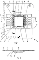
- FIG. 1 shows a lead frame according to the invention, which is denoted overall by 1.
- a lead frame is part of a strip that is usually consists of ten individual lead frames 1.
- the lead frame 1 has various circular recesses in the outer area 2 on that for the automated further transport of the serve entire strip with the plurality of lead frame 1.
- the elongated recesses 3 serve as a predetermined breaking point to separate the individual lead frames 1 from the entire strip.
- the lead frame 1 has two rows of each five connection fingers that face each other.
- the Connection fingers are designated 4.
- the stability of the connecting fingers 4 is through a connecting web 5, each connecting a series of connecting fingers increases.
- the connecting bridge 5 is after being pressed into a molding compound housing away.
- the connecting fingers 4 have a Silver coating 19, so that better contact making in the bond connection of the connecting fingers 4 with a Semiconductor chip is made possible.
- a heatslug 6 is arranged opposite the lead frame 1 is slightly lowered.
- the Heatslug 6 is from four fasteners 7 held, the connection attachment 8 to lead frame 1.
- a further recess 9 is provided so that one is dashed shown breaking edge 10 arises on the after pouring of an integrated circuit the outer area of the Lead frame 1 can be separated.
- One of the fasteners 7, in this case the one shown at the top left, has an electrical connection 11 which is integral with the connector 8 is formed and the closest Connection finger 4 contacted.
- a connecting finger 4 designed as a ground connection for the heatslug 6.
- the heatslug 6 is rectangular in shape and points to the extensions 12 on both ends.
- FIG. 2 shows a section along the line A-A from FIG. 1, which runs through one of the connecting fingers 4. Of the Cut through the connecting finger is from the elongated recess 3 and the hole 13 interrupted. In the central area of the lead frame, the contour of the recess 9 is indicated.
- the heatslug 6 is at a certain distance, also called downset, removed from the lead frame.
- the heatslug 6 has projections 14 at the corners, which are connected to the fastening element 7 are connected.
- the projections 14 are only formed over a fraction of the depth of the heatslug 6.
- the Fastening elements 7 are on the projections 14 Welding points 15 connected, which are also shown in Fig. 1 are. These welding spots are created with a laser.
- FIG. 3 shows a section along the line B-B in FIG. 1.
- the connecting fingers 4 are shown and in heatslug 6 a notch 16 is provided with which an additional anchoring of the heatslug is achieved when the housing is pressed in.
- connection attachment 8 on the level of the entire lead frame 1 is formed, a connecting part 17 and a flat end region 18.
- This extended areal End region 18 is offset parallel to the lead frame trained and with a weld spot 15 on the projection 14 of the heatslug 6 arranged, the projection 14 the corner area of the heatslug 6 expanded square and in its shape the flat expansion of the end region 18 of the fastening element 7 corresponds.
- Connecting part formed with two bends through which an overall Z-shaped fastener is created, which be formed in one piece. The bends can be used to protect the material is also rounded.
- the breaking edge 10 is to a parallel offset between connection attachment 8 and end area 18 .
Abstract
Description
Die Erfindung betrifft einen Zuleitungsrahmen zur Verwendung in einem Leistungsgehäuse mit Anschlußfingern und Befestigungsmitteln. Weiterhin betrifft die Erfindung ein Bauteil zur Verwendung in einem Leistungsgehäuse für einen integrierten Schaltkreis mit einem Heatslug und einem Zuleitungsrahmen, der Anschlußfinger und Befestigungsmittel zur Verbindung mit dem Heatslug aufweist.The invention relates to a lead frame for use in a power housing with connecting fingers and fasteners. The invention further relates to a component for use in a power package for an integrated circuit with a heatslug and a lead frame, the connecting finger and fasteners for connection to the Has heatslug.
Solche Zuleitungsrahmen, die auch als Leadframe bezeichnet werden, werden in Leistungsgehäusen für integrierte Schaltkreise üblicherweise in Kombination mit einem Heatslug verwendet, der in der Regel aus einem metallischen Block besteht und zu einer besseren Verteilung der Wärme im Gehäuse und damit einer besseren Wärmeabfuhr dient.Such lead frames, which are also referred to as lead frames, are used in power packages for integrated circuits usually used in combination with a heatslug that usually consists of a metallic block and one better heat distribution in the housing and thus a better one Heat dissipation is used.
Es ist bekannt, den Heatslug mit vier elektrischen Anschlüssen des Leadframes, die auch als Pins bezeichnet werden, am Leadframe zu befestigen. Diese Anschlüsse stehen dann für eine elektrische Kontaktierung nicht mehr zur Verfügung.It is known the heatslug with four electrical connections of the lead frame, also referred to as pins, on the lead frame to fix. These connections then stand for one electrical contacting no longer available.
Der Erfindung liegt die Aufgabe zugrunde, einen Zuleitungsrahmen und ein Bauteil der eingangs genannten Art zu schaffen, welche einfach herstellbar sind und eine möglichst gute Flächenausnutzung erlauben.The invention has for its object to provide a lead frame and a component of the type mentioned, which are easy to manufacture and allow the best possible use of space.
Zur Lösung dieser Aufgabe wird der eingangs genannte Zuleitungsrahmen so ausgebildet, daß die Befestigungsmittel zweifach abgewinkelte Befestigungselemente aufweisen, so daß ein Endbereich der Befestigungselemente gegenüber dem Zuleitungsrahmen parallel versetzt ist, die Endbereiche der Befestigungselemente zur Herstellung einer Verbindung flächig ausgebildet sind und eines der Befestigungselemente elektrisch leitend mit einem der Anschlußfinger verbunden ist.To solve this problem, the supply frame mentioned at the beginning designed so that the fastening means twice have angled fasteners so that an end region the fasteners opposite the lead frame is offset in parallel, the end portions of the fasteners are flat to produce a connection and one of the fasteners electrically conductive with one of the Connection finger is connected.
Das eingangs genannte Bauteil, welches einen Heatslug und einen Zuleitungsrahmen aufweist, wird zur Lösung der Aufgabe so weiter entwickelt, daß die Befestigungsmittel zweifach abgewinkelte Befestigungselemente aufweisen, ein Endbereich der Befestigungselemente gegenüber dem Zuleitungsrahmen parallel versetzt ist, die Endbereiche der Befestigungselemente zur Verbindung mit dem Heatslug flächig ausgebildet sind und eines der Befestigungselemente elektrisch leitend mit einem der Anschlußfinger verbunden ist, wobei dieser Anschlußfinger einen Masseanschluß für den Heatslug darstellt.The component mentioned at the beginning, which includes a heatslug and a Has lead frame, will continue to solve the problem developed that the fastener angled twice Have fasteners, an end portion of the fasteners offset parallel to the lead frame is, the end portions of the fasteners for connection are flat with the heatslug and one of the fasteners electrically conductive with one of the connecting fingers is connected, this connection finger a ground connection for the heatslug.
Durch diese Maßnahmen ergeben sich die Vorteile, daß der Heatslug mit einem gewissen Versatz oder Abstand gegenüber den Anschlußfingern des Zuleitungsrahmens angeordnet werden kann und die Anschlußfinger dadurch näher an Kontaktflächen an einer Oberseite eines integrierten Schaltkreises, positioniert werden können. Die flächigen Endbereiche der Befestigungselemente spannen eine Ebene auf, die parallel versetzt zu der Ebene des Zuleitungsrahmens liegt. In dieser Ebene erfolgt die Befestigung des Heatslugs. Auf dem Heatslug und damit auch in dieser Ebene erfolgt die Befestigung des integrierten Schaltkreises. Durch die Verwendung dieser zusätzlichen Befestigungselemente steht bei gleicher Gehäusegröße eine größere Anzahl von elektrisch aktiven Anschlußfingern oder Pins zum Anschluß an den integrierten Schaltkreis zur Verfügung.These measures have the advantages that the heatslug with a certain offset or distance from the connection fingers of the lead frame can be arranged and the connecting fingers thereby closer to contact surfaces on a Top of an integrated circuit can. The flat end areas of the fasteners span a plane that is offset parallel to the plane of the Lead frame is. The attachment takes place at this level of the heatslug. On the heatslug and therefore also in this one The integrated circuit is attached on the level. By using these additional fasteners there is a larger number of electrical with the same housing size active connection fingers or pins for connection to the integrated circuit available.
In einer bevorzugten Ausführungsform sind vier Befestigungselemente vorgesehen. Eine stabile Befestigung ist auch mit drei Befestigungselementen oder mehr als vier Befestigungselementen denkbar. Besonders günstig ist jedoch die Anordnung von vier Befestigungselementen in den Ecken des Zuleitungsrahmens.In a preferred embodiment there are four fastening elements intended. A stable attachment is also with three Fasteners or more than four fasteners conceivable. However, the arrangement of four is particularly favorable Fasteners in the corners of the lead frame.
Die zweifach abgewinkelten Befestigungselemente sind in einer Weiterbildung Z-förmig ausgebildet. In einer anderen Ausführungsform sind die direkten Übergänge der zweifach abgewinkelten Befestigungselemente abgerundet ausgebildet, um keinen echten Knick zu erzeugen und Materialbruch zu vermeiden. Die flächig ausgebildeten Endbereiche der Befestigungselemente sind bevorzugt zur Schweißpunktbefestigung ausgelegt. Denkbar ist auch eine Niet-, Kleb- oder Lötbefestigung.The double angled fasteners are in one Continuing education Z-shaped. In another embodiment are the direct transitions of the double angled Fastening elements are rounded, not a real one To create a kink and to avoid material breakage. The flat trained end regions of the fasteners preferably designed for spot welding. Is conceivable also a rivet, adhesive or solder attachment.
In einer besonders bevorzugten Ausführungsform weist der Zuleitungsrahmen zwei sich gegenüberliegende Reihen von Anschlußfingern auf, wobei die Befestigungselemente an den beiden anderen sich gegenüberliegenden Seiten des Zuleitungsrahmens befestigt sind. Eine solche Anordnung wird insbesondere bei einem DSO(Dual Small Outline)-Leistungsgehäuse verwirklicht. Bevorzugt sind die Befestigungselemente dabei an einer Bruchkante des Zuleitungsrahmens ausgebildet, so daß nach Eingießen des Zuleitungsrahmens und des integrierten Schaltkreises in ein Preßmassengehäuse die überstehenden Bereiche des Zuleitungsrahmens problemlos abgebrochen werden können. Der Zuleitungsrahmen ist bevorzugt zur Verwendung in einem DSO-Gehäuse ausgebildet.In a particularly preferred embodiment, the lead frame has two opposite rows of connecting fingers on, with the fasteners attached to the other two attached to opposite sides of the lead frame are. Such an arrangement is particularly in one DSO (Dual Small Outline) power package realized. Prefers the fasteners are on a broken edge of the lead frame so that after pouring the Lead frame and the integrated circuit in one Molding compound housing the protruding areas of the lead frame can be easily canceled. The lead frame is preferably designed for use in a DSO housing.
In einer anderen Weiterbildung weist der Heatslug Vorsprünge auf, die in ihren Abmessungen den flächigen Endbereichen der Befestigungselemente entsprechen. Günstigerweise sind vier solcher Vorsprünge jeweils in den Ecken des Heatslugs angeordnet. Der Vorsprung ist dabei günstigerweise einstückig mit dem Heatslug ausgebildet, aber nicht so dick wie dieser, so daß der Vorsprung eine obere Kante oder oberen Vorsprung des Heatslugs darstellt. In another development, the heatslug has protrusions on, the dimensions of the flat end regions of the Fasteners correspond. Four are favorably such Projections are arranged in the corners of the heatslug. The projection is advantageously in one piece with the Heatslug trained, but not as thick as this one, so the Projection an upper edge or upper projection of the heatslug represents.
Nachfolgend wird die Erfindung anhand eines in der Zeichnung dargestellten Ausführungsbeispiels weiter erläutert. Im einzelnen zeigen die schematischen Darstellungen in:
- Fig. 1
- eine Draufsicht auf ein erfindungsgemäßes Leadframe;
- Fig. 2
- einen Querschnitt entlang der Linie A-A des erfindungsgemäßen Leadframes;
- Fig. 3
- einen Querschnitt entlang der Linie B-B des erfindungsgemäßen Leadframes;
- Fig. 4
- eine seitliche Detailansicht eines Befestigungselements und
- Fig. 5
- eine Draufsicht auf das Befestigungselement gemäß Fig. 4.
- Fig. 1
- a plan view of a leadframe according to the invention;
- Fig. 2
- a cross section along the line AA of the leadframe according to the invention;
- Fig. 3
- a cross section along the line BB of the leadframe according to the invention;
- Fig. 4
- a detailed side view of a fastener and
- Fig. 5
- 4 shows a plan view of the fastening element according to FIG. 4.
In Fig. 1 ist ein erfindungsgemäßer Zuleitungsrahmen dargestellt,
der insgesamt mit 1 bezeichnet ist. Ein solcher Zuleitungsrahmen
ist Bestandteil eines Streifens, der üblicherweise
aus zehn einzelnen Zuleitungsrahmen 1 besteht. Der Zuleitungsrahmen
1 weist im Außenbereich verschiedene kreisförmige Ausnehmungen
2 auf, die zum automatisierten Weitertransport des
gesamten Streifens mit der Vielzahl von Zuleitungsrahmen 1 dienen.
Die länglichen Ausnehmungen 3 dienen als Sollbruchstelle
zum Trennen der einzelnen Zuleitungsrahmen 1 aus dem Gesamtstreifen.
Der Zuleitungsrahmen 1 weist zwei Reihen von jeweils
fünf Anschlußfingern auf, die sich gegenüberliegen. Die
Anschlußfinger sind mit 4 bezeichnet. Die Stabilität der Anschlußfinger
4 wird durch einen Verbindungssteg 5, der jeweils
eine Reihe von Anschlußfingern verbindet, erhöht. Der Verbindungssteg
5 wird nach dem Einpressen in ein Preßmassengehäuse
entfernt. Im vorderen Bereich weisen die Anschlußfinger 4 eine
Silberbeschichtung 19 auf, so daß eine bessere Kontaktherstellung
bei der Bondverbindung der Anschlußfinger 4 mit einem
Halbleiterchip ermöglicht wird. Zentral zwischen den Anschlußfingern
4 ist ein Heatslug 6 angeordnet, der gegenüber dem Zuleitungsrahmen
1 etwas abgesenkt ist. Der Heatslug 6 wird von
vier Befestigungselementen 7 gehalten, die eine Anschlußbefestigung
8 zum Zuleitungsrahmen 1 aufweisen. In diesem Bereich
ist eine weitere Ausnehmung 9 vorgesehen, so daß eine gestrichelt
dargestellte Bruchkante 10 entsteht, an der nach dem Eingießen
eines integrierten Schaltkreises der äußere Bereich des
Zuleitungsrahmens 1 abgetrennt werden kann. Eines der Befestigungselemente
7, in diesem Fall das links oben dargestellte,
weist eine elektrische Verbindung 11 auf, die einstückig mit
der Anschlußbefestigung 8 ausgebildet ist und den nächstgelegenen
Anschlußfinger 4 kontaktiert. Auf diese Weise wird ein Anschlußfinger
4 als Masseanschluß für den Heatslug 6 ausgebildet.
Der Heatslug 6 ist von rechteckiger Form und weist an den
beiden Stirnseiten Erweiterungen 12 auf.1 shows a lead frame according to the invention,
which is denoted overall by 1. Such a lead frame
is part of a strip that is usually
consists of ten
In Fig. 2 ist ein Schnitt entlang der Linie A-A aus Fig. 1 dargestellt,
der durch einen der Anschlußfinger 4 verläuft. Der
Schnitt durch den Anschlußfinger wird von der länglichen Ausnehmung
3 und dem Loch 13 unterbrochen. Im zentralen Bereich
des Zuleitungsrahmens ist die Kontur der Ausnehmung 9 angedeutet.
Der Heatslug 6 befindet sich mit einem gewissen Abstand,
auch Downset genannt, vom Zuleitungsrahmen entfernt. Der Heatslug
6 weist an den Ecken Vorsprünge 14 auf, die mit dem Befestigungselement
7 verbunden sind. Die Vorsprünge 14 sind nur
über einen Bruchteil der Tiefe des Heatslug 6 ausgebildet. Die
Befestigungselemente 7 sind an den Vorsprüngen 14 durch
Schweißpunkte 15 verbunden, die auch in Fig. 1 dargestellt
sind. Diese Schweißpunkte werden mit einem Laser erzeugt. 2 shows a section along the line A-A from FIG. 1,
which runs through one of the connecting
In Fig. 3 ist ein Schnitt entlang der Linie B-B in Fig. 1 dargestellt.
Neben dem Zuleitungsrahmen 1 sind im zentralen Bereich
die Anschlußfinger 4 dargestellt und im Heatslug 6 ist
eine Kerbe 16 vorgesehen, mit der eine zusätzliche Verankerung
des Heatslugs beim Einpressen des Gehäuses erreicht wird.FIG. 3 shows a section along the line B-B in FIG. 1.
In addition to the
In den Fig. 4 und 5 sind ein Querschnitt und eine Draufsicht
auf ein Befestigungselement 7 und den dazugehörigen Teil eines
Heatslug 6 dargestellt. Das Befestigungselement 7 weist eine
Anschlußbefestigung 8 auf, die in der Ebene des gesamten Zuleitungsrahmens
1 ausgebildet ist, einen Verbindungsteil 17 und
einen flächig erweiterten Endbereich 18 auf. Dieser flächig erweiterte
Endbereich 18 ist parallel versetzt zum Zuleitungsrahmen
ausgebildet und mit einem Schweißpunkt 15 auf dem Vorsprung
14 des Heatslug 6 angeordnet, wobei der Vorsprung 14 den Eckbereich
des Heatslug 6 quadratisch erweitert und in seiner Form
der flächigen Erweiterung des Endbereichs 18 des Befestigungselements
7 entspricht. Um einen parallelen Versatz zwischen Anschlußbefestigung
8 und Endbereich 18 zu erreichen, ist das
Verbindungsteil mit zwei Abwinklungen ausgebildet, durch die
ein insgesamt Z-förmiges Befestigungselement entsteht, welches
einstückig ausgebildet sein. Die Abwinklungen können zur Materialschonung
auch abgerundet ausgebildet ist. Am Ende der Anschlußbefestigung
8 befindet sich die Bruchkante 10. 4 and 5 are a cross section and a plan view
on a
- 11
- ZuleitungsrahmenLead frame
- 22nd
- kreisförmige Ausnehmungencircular recesses
- 33rd
- längliche Ausnehmungenelongated recesses
- 44th
- AnschlußfingerConnecting finger
- 55
- VerbindungsstegConnecting bridge
- 66
- HeatslugHeatslug
- 77
- BefestigungselementFastener
- 88th
- AnschlußbefestigungConnection attachment
- 99
- AusnehmungRecess
- 1010th
- BruchkanteBreaking edge
- 1111
- elektrische Verbindungelectrical connection
- 1212th
- Erweiterungextension
- 1313
- Lochhole
- 1414
- Vorsprunghead Start
- 1515
- SchweißpunktSpot weld
- 1616
- Kerbescore
- 1717th
- VerbindungsteilConnecting part
- 1818th
- EndbereichEnd area
- 1919th
- SilberbeschichtungSilver coating
Claims (12)
dadurch gekennzeichnet,
characterized by
dadurch gekennzeichnet,
characterized,
dadurch gekennzeichnet,
characterized,
dadurch gekennzeichnet,
characterized,
dadurch gekennzeichnet,
characterized,
dadurch gekennzeichnet,
characterized by
dadurch gekennzeichnet,
characterized by
dadurch gekennzeichnet,
characterized by
dadurch gekennzeichnet,
characterized by
dadurch gekennzeichnet,
characterized by
dadurch gekennzeichnet,
characterized by
dadurch gekennzeichnet,
characterized by
Applications Claiming Priority (2)
| Application Number | Priority Date | Filing Date | Title |
|---|---|---|---|
| DE19626088 | 1996-06-28 | ||
| DE19626088 | 1996-06-28 |
Publications (1)
| Publication Number | Publication Date |
|---|---|
| EP0817265A1 true EP0817265A1 (en) | 1998-01-07 |
Family
ID=7798368
Family Applications (1)
| Application Number | Title | Priority Date | Filing Date |
|---|---|---|---|
| EP97110219A Withdrawn EP0817265A1 (en) | 1996-06-28 | 1997-06-23 | Lead frame for an integrated circuit and package comprising such a lead frame and a heat slug |
Country Status (2)
| Country | Link |
|---|---|
| EP (1) | EP0817265A1 (en) |
| JP (1) | JPH1065085A (en) |
Cited By (2)
| Publication number | Priority date | Publication date | Assignee | Title |
|---|---|---|---|---|
| DE19844873A1 (en) * | 1998-09-30 | 2000-04-13 | Possehl Electronic Gmbh | Carrier arrangement to accommodate semiconducting element has carrying frame to which heat conducting body is attached using at least one welded joint, e.g. laser welded joint |
| WO2007050038A1 (en) * | 2005-10-25 | 2007-05-03 | Infineon Technologies Ag | Method of manufacture of encapsulated package |
Families Citing this family (1)
| Publication number | Priority date | Publication date | Assignee | Title |
|---|---|---|---|---|
| CN107598324B (en) * | 2017-10-23 | 2024-02-20 | 中国电子科技集团公司第四十三研究所 | Packaged product preheating device |
Citations (10)
| Publication number | Priority date | Publication date | Assignee | Title |
|---|---|---|---|---|
| FR2487580A1 (en) * | 1980-07-22 | 1982-01-29 | Thomson Csf Mat Tel | Flat package with exposed heat sink, for semiconductor chip - where heat sink and connector tags are made from single metal strip |
| GB2084796A (en) * | 1980-09-17 | 1982-04-15 | Hitachi Ltd | Mounting and cooling arrangements for semiconductor devices |
| JPS58219755A (en) * | 1982-06-14 | 1983-12-21 | Nec Corp | Integrated circuit package |
| EP0443508A1 (en) * | 1990-02-22 | 1991-08-28 | STMicroelectronics S.r.l. | Leadframe for packages of integrated power devices |
| EP0503072A1 (en) * | 1990-09-10 | 1992-09-16 | Fujitsu Limited | Semiconductor device and its manufacturing process |
| EP0588491A2 (en) * | 1992-08-14 | 1994-03-23 | Texas Instruments Incorporated | Lead frame for integrated circuits and a method for optimizing heat dissipation |
| US5345106A (en) * | 1990-06-01 | 1994-09-06 | Robert Bosch Gmbh | Electronic circuit component with heat sink mounted on a lead frame |
| US5497032A (en) * | 1993-03-17 | 1996-03-05 | Fujitsu Limited | Semiconductor device and lead frame therefore |
| EP0712160A2 (en) * | 1994-11-14 | 1996-05-15 | Texas Instruments Incorporated | Improvements in or relating to semiconductor devices |
| JPH08125082A (en) * | 1994-10-24 | 1996-05-17 | Sanyo Electric Co Ltd | Lead frame and manufacture of semiconductor device |
-
1997
- 1997-06-20 JP JP9180798A patent/JPH1065085A/en active Pending
- 1997-06-23 EP EP97110219A patent/EP0817265A1/en not_active Withdrawn
Patent Citations (10)
| Publication number | Priority date | Publication date | Assignee | Title |
|---|---|---|---|---|
| FR2487580A1 (en) * | 1980-07-22 | 1982-01-29 | Thomson Csf Mat Tel | Flat package with exposed heat sink, for semiconductor chip - where heat sink and connector tags are made from single metal strip |
| GB2084796A (en) * | 1980-09-17 | 1982-04-15 | Hitachi Ltd | Mounting and cooling arrangements for semiconductor devices |
| JPS58219755A (en) * | 1982-06-14 | 1983-12-21 | Nec Corp | Integrated circuit package |
| EP0443508A1 (en) * | 1990-02-22 | 1991-08-28 | STMicroelectronics S.r.l. | Leadframe for packages of integrated power devices |
| US5345106A (en) * | 1990-06-01 | 1994-09-06 | Robert Bosch Gmbh | Electronic circuit component with heat sink mounted on a lead frame |
| EP0503072A1 (en) * | 1990-09-10 | 1992-09-16 | Fujitsu Limited | Semiconductor device and its manufacturing process |
| EP0588491A2 (en) * | 1992-08-14 | 1994-03-23 | Texas Instruments Incorporated | Lead frame for integrated circuits and a method for optimizing heat dissipation |
| US5497032A (en) * | 1993-03-17 | 1996-03-05 | Fujitsu Limited | Semiconductor device and lead frame therefore |
| JPH08125082A (en) * | 1994-10-24 | 1996-05-17 | Sanyo Electric Co Ltd | Lead frame and manufacture of semiconductor device |
| EP0712160A2 (en) * | 1994-11-14 | 1996-05-15 | Texas Instruments Incorporated | Improvements in or relating to semiconductor devices |
Non-Patent Citations (2)
| Title |
|---|
| PATENT ABSTRACTS OF JAPAN vol. 008, no. 070 (E - 235) 3 April 1984 (1984-04-03) * |
| PATENT ABSTRACTS OF JAPAN vol. 096, no. 009 30 September 1996 (1996-09-30) * |
Cited By (4)
| Publication number | Priority date | Publication date | Assignee | Title |
|---|---|---|---|---|
| DE19844873A1 (en) * | 1998-09-30 | 2000-04-13 | Possehl Electronic Gmbh | Carrier arrangement to accommodate semiconducting element has carrying frame to which heat conducting body is attached using at least one welded joint, e.g. laser welded joint |
| DE19844873C2 (en) * | 1998-09-30 | 2003-11-13 | Possehl Electronic Gmbh | Carrier arrangement for receiving a semiconductor element and method for producing a laser welded connection |
| WO2007050038A1 (en) * | 2005-10-25 | 2007-05-03 | Infineon Technologies Ag | Method of manufacture of encapsulated package |
| US7674657B2 (en) | 2005-10-25 | 2010-03-09 | Infineon Technologies Ag | Method of manufacture of encapsulated package |
Also Published As
| Publication number | Publication date |
|---|---|
| JPH1065085A (en) | 1998-03-06 |
Similar Documents
| Publication | Publication Date | Title |
|---|---|---|
| DE3913221C2 (en) | Semiconductor arrangement with lead frame and molded resin housing | |
| EP0627104B1 (en) | Contacting device for a chip card | |
| DE2901416A1 (en) | ARRANGEMENT FOR ELECTRICALLY CONNECTING A VARIETY OF CONNECTIONS | |
| DE4115128A1 (en) | SEMICONDUCTOR PERFORMANCE ARRANGEMENT FOR HIGH-FREQUENCY APPLICATIONS | |
| DE2315711A1 (en) | METHOD OF CONTACTING INTEGRATED CIRCUITS HOUSED IN A SEMICONDUCTOR BODY WITH THE AID OF A FIRST CONTACTING FRAME | |
| EP0817265A1 (en) | Lead frame for an integrated circuit and package comprising such a lead frame and a heat slug | |
| DE3639053C2 (en) | Integrated circuit arrangement | |
| DE19732807B4 (en) | Integrated circuit component | |
| EP0057253A2 (en) | System carrier tape with a plurality of system carriers for integrated circuits | |
| DE3619636A1 (en) | Housing for integrated circuits | |
| DE102017103476B4 (en) | Circuit source package arrangement | |
| DE2837318A1 (en) | Solder connection formed by gap in disc - placed between conducting paths on printed circuit board so that solder beads join profiled ends of path | |
| DE4213250C2 (en) | Double-sided SMD-populated circuit board with special measures to reduce alternating temperature voltages | |
| DE19723431A1 (en) | Semiconductor component provided with an ESD protection circuit | |
| DE10318589A1 (en) | Printed circuit board assembly | |
| DE3510638C1 (en) | Inductive miniature component, especially a miniature coil, and a method for producing such a component | |
| EP0794571B1 (en) | Prepunched leadframe for making electronic components | |
| DE19549097A1 (en) | Semiconductor package for surface mounting | |
| DE10158770B4 (en) | Lead frame and component with a lead frame | |
| DE4404312C1 (en) | Connection device for microwave device unilateral planar line | |
| DE19506958C2 (en) | Semiconductor device with good thermal behavior | |
| DE102005001151A1 (en) | Component arrangement for serial connection with high voltage application has semiconductor chip, load connections, and control port whereby first and second load connection are arranged on opposite sides of semiconductor chip | |
| EP2302987B1 (en) | Integration of SMD components in an IC housing | |
| EP1186037B1 (en) | Multi-chip module for leads-on-chip (loc) assembly and method for production of the same. | |
| DE19733416A1 (en) | Packaging for semiconductor chip |
Legal Events
| Date | Code | Title | Description |
|---|---|---|---|
| PUAI | Public reference made under article 153(3) epc to a published international application that has entered the european phase |
Free format text: ORIGINAL CODE: 0009012 |
|
| AK | Designated contracting states |
Kind code of ref document: A1 Designated state(s): AT BE CH DE DK ES FI FR GB GR IE IT LI LU MC NL PT SE |
|
| AKX | Designation fees paid | ||
| RBV | Designated contracting states (corrected) | ||
| RBV | Designated contracting states (corrected) | ||
| STAA | Information on the status of an ep patent application or granted ep patent |
Free format text: STATUS: THE APPLICATION IS DEEMED TO BE WITHDRAWN |
|
| 18D | Application deemed to be withdrawn |
Effective date: 19980708 |