EP0815778A1 - Improvements for systems with differential shaping of back supports of office chairs - Google Patents
Improvements for systems with differential shaping of back supports of office chairs Download PDFInfo
- Publication number
- EP0815778A1 EP0815778A1 EP96440052A EP96440052A EP0815778A1 EP 0815778 A1 EP0815778 A1 EP 0815778A1 EP 96440052 A EP96440052 A EP 96440052A EP 96440052 A EP96440052 A EP 96440052A EP 0815778 A1 EP0815778 A1 EP 0815778A1
- Authority
- EP
- European Patent Office
- Prior art keywords
- bar
- backrest
- torsion
- seat
- user
- Prior art date
- Legal status (The legal status is an assumption and is not a legal conclusion. Google has not performed a legal analysis and makes no representation as to the accuracy of the status listed.)
- Granted
Links
Images


Classifications
-
- A—HUMAN NECESSITIES
- A47—FURNITURE; DOMESTIC ARTICLES OR APPLIANCES; COFFEE MILLS; SPICE MILLS; SUCTION CLEANERS IN GENERAL
- A47C—CHAIRS; SOFAS; BEDS
- A47C1/00—Chairs adapted for special purposes
- A47C1/02—Reclining or easy chairs
- A47C1/031—Reclining or easy chairs having coupled concurrently adjustable supporting parts
- A47C1/032—Reclining or easy chairs having coupled concurrently adjustable supporting parts the parts being movably-coupled seat and back-rest
- A47C1/03294—Reclining or easy chairs having coupled concurrently adjustable supporting parts the parts being movably-coupled seat and back-rest slidingly movable in the base frame, e.g. by rollers
-
- A—HUMAN NECESSITIES
- A47—FURNITURE; DOMESTIC ARTICLES OR APPLIANCES; COFFEE MILLS; SPICE MILLS; SUCTION CLEANERS IN GENERAL
- A47C—CHAIRS; SOFAS; BEDS
- A47C1/00—Chairs adapted for special purposes
- A47C1/02—Reclining or easy chairs
- A47C1/031—Reclining or easy chairs having coupled concurrently adjustable supporting parts
- A47C1/032—Reclining or easy chairs having coupled concurrently adjustable supporting parts the parts being movably-coupled seat and back-rest
- A47C1/03261—Reclining or easy chairs having coupled concurrently adjustable supporting parts the parts being movably-coupled seat and back-rest characterised by elastic means
- A47C1/03266—Reclining or easy chairs having coupled concurrently adjustable supporting parts the parts being movably-coupled seat and back-rest characterised by elastic means with adjustable elasticity
-
- A—HUMAN NECESSITIES
- A47—FURNITURE; DOMESTIC ARTICLES OR APPLIANCES; COFFEE MILLS; SPICE MILLS; SUCTION CLEANERS IN GENERAL
- A47C—CHAIRS; SOFAS; BEDS
- A47C1/00—Chairs adapted for special purposes
- A47C1/02—Reclining or easy chairs
- A47C1/031—Reclining or easy chairs having coupled concurrently adjustable supporting parts
- A47C1/032—Reclining or easy chairs having coupled concurrently adjustable supporting parts the parts being movably-coupled seat and back-rest
- A47C1/03255—Reclining or easy chairs having coupled concurrently adjustable supporting parts the parts being movably-coupled seat and back-rest with a central column, e.g. rocking office chairs
-
- A—HUMAN NECESSITIES
- A47—FURNITURE; DOMESTIC ARTICLES OR APPLIANCES; COFFEE MILLS; SPICE MILLS; SUCTION CLEANERS IN GENERAL
- A47C—CHAIRS; SOFAS; BEDS
- A47C1/00—Chairs adapted for special purposes
- A47C1/02—Reclining or easy chairs
- A47C1/031—Reclining or easy chairs having coupled concurrently adjustable supporting parts
- A47C1/032—Reclining or easy chairs having coupled concurrently adjustable supporting parts the parts being movably-coupled seat and back-rest
- A47C1/03261—Reclining or easy chairs having coupled concurrently adjustable supporting parts the parts being movably-coupled seat and back-rest characterised by elastic means
- A47C1/03277—Reclining or easy chairs having coupled concurrently adjustable supporting parts the parts being movably-coupled seat and back-rest characterised by elastic means with bar or leaf springs
- A47C1/03279—Reclining or easy chairs having coupled concurrently adjustable supporting parts the parts being movably-coupled seat and back-rest characterised by elastic means with bar or leaf springs of torsion type
Definitions
- the present invention relates to office chairs with backrests adjustable, and it aims more specifically at improvements adjustable backrest systems with organs for independent adjustment of the thoracic portion and the portion lumbar of these files in order to make them more comfortable thanks to their ability to better adapt to different user back configurations.
- the mechanism determining the adjustable support of the lumbar portion is mounted fixed by relative to the column on which the seat rests swivel, that is to say that the seat base is fixed. Furthermore, in this same structure, the elements transmitting the action of this mechanism to said lumbar portion are relatively close to each other laterally due to the nature of this mechanism, whereas on the contrary it would be desirable for them to be located at the outer edge of the backrest.
- the present invention eliminates all of these drawbacks, thanks to a other mechanism, involving means ensuring resistance elastic of each of the support elements by elastic deformation under the action of a torsional stress.
- These means can in particular be torsion springs, bars torsion or combinations of the two, but preferably according to the invention, they consist of a couple of torsion bars.
- these means are associated with each other by in such a way that the second intervenes sequentially with respect to the first.
- the second of these bars is mounted relative to the first so as to intervene after to have undergone the action of the deformation of the first.
- a first torsion bar determines the inclination of the thoracic portion of the backrest by tilting, around the fixed seat box, a first crew carrying a bar substantially vertical support from the high point of the backrest, and a second bar of torsion determines the inclination of the lumbar portion of the backrest, by tilting, around said first crew, of a second crew carrying columns supporting a substantially horizontal grab bar of the arched area adapting to the user's lumbar area.
- the first crew consists essentially of a torsion bar horizontal constant section, working over its entire length, fixed to a end to a concentric sheath rotatably attached to the fixed housing of the seat, and serving as a reminder of the rotation of said sheath, which carries a casing tilting to which is fixed a corner bar whose top is articulated to a point on the backrest under pressure from the back of the rib cage the user, and preferably comprising at its other end means for preload allowing the hardness of the reaction to be adjusted at will of the file at said pressure.
- the second crew consists essentially of a torsion bar horizontal preferably formed of four equal bars with square section, in order to allow the development of a higher degree of twist, this composite bar serving similarly to the previous one, as an organ to a pair of sleeves rotatably attached to said tilting casing and carrying at each end a vertical column, preferably at height adjustable, these columns supporting a determining horizontal grab bar, behind the backrest, the optimal degree of curvature of the lumbar region of the body of the user, ie the base of the spine and the pelvis.
- the central area of this second torsion bar includes prestressing means regulating at will the reaction of the lumbar portion of the backrest at user pressure.
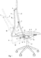
- the mobile elements are shown in solid lines in rest position, and in broken line in deformed position under the effect of user body.
- the seat according to the invention comprises a fixed casing B based on a pivoting column system P.
- the seat A of the seat On the fixed box B is mounted the seat A of the seat, having preferably certain features which will be explained below.
- first torsion bar 1 ( Figure 2) carrying a first crew consisting of a tilting casing 2 integral a sleeve 11 concentric with the bar 1, to which it is fixed at one end 1a, this sleeve being rotatably attached to the housing B, and carrying a bar 3, having a first section 3a, oriented towards the rear substantially in the horizontal extension of the housing 2, and a second section 3b, at right angles with section 3a, extending upwards behind the backrest D which is attached to it hooked by a system of links 4 ensuring its maintenance whatever the height, preferably with the interposition of a silent block.
- the second torsion bar 5 (figures 3 and 3a), mounted in a pair of rotary sleeves 12 and 13 welded to ends 5a and 5b of the bar, and carrying at their two external ends columns 6 substantially vertical, or slightly inclined backwards at rest, which are located on either side of the backrest, and which are joined to their upper part by a horizontal grab bar 7 in front of which is arch the lower portion of the backrest.
- the height of the columns 6 can be adjusted, for example by means of racks, with which cooperate with detachable elastic pawls or fingers or analogues (as shown schematically in 14). As one can see in FIG.
- the bar 5 is made up of four bars 5a, 5b, 5c, 5d of identical square sections, but each equal to a quarter of the section of the bar 5.
- the contact surfaces of the small bars 5a, 5b, 5c, 5d slide against each other, facilitating the overall deformation by twisting the bar 5.
- the user's lumbar portion will exert pressure on the lower arched part of the backrest D and the grab bar 7, with the same elastic holding effect, in degree and hardness. Moving in tilting forward of this lower portion is limited by stopper adjustable tabs fixed to the sheath against stops 16 fixed to the seat.
- the torsion bar 1 may include a prestressing system to adapt the hardness.
- a member 8 actuated by a button 9 located under the seat, and which tends to subject the bar 1 to a beginning of torsion, by support on the fixed base B even before the user exerts his weight on the folder. This beginning of torsion makes it harder to continue the user action.
- torsion bar 5 Similar means can be used with torsion bar 5, such as illustrated in Figure 3.
- the prestressing is exerted, not at the free end of the bar, as in the previous case, but at the center 10 of the bar, which then works twice as much on each side to reach the same inclination of the columns 6.
- the bar 5 carries a housing 15 (FIG. 3a), the tilting of which, controlled by the rod 10 'screwed into the housing 2, modifies the torsion of the bar 5.
- This structure ensures symmetry of operation, the bar serving at the same rotation axis time.
- the tilt point 1 of the housing 2 is located at the front of the pivoting column P. This results in a very low inclination of the rear portion of the seat A, (the front portion resting on the case B) even for a relatively large tilting of the backrest D, this which is sometimes sought after today. For example, for a report of distances of 2.5, backrest tilting up to 24 ° angle will cause an inclination of the seat only about 9 °. This contributes to overall seat comfort.
- the top of the seat A is convex, as shown in C, unlike the usual geometry in this type of seat.
- the backrest D must be flexible enough to allow independent bending of its upper portion and its portion lower.
- a composite material may be used, for example formed of glass fibers embedded in polyether foam; so the seat comfort is formed by the curve and not by the thickness of the foam.
Abstract
Description
La présente invention concerne les sièges de bureau à dossier réglable, et elle vise plus particulièrement des perfectionnements aux systèmes de dossiers réglables comportant des organes pour le réglage indépendant de la portion thoracique et de la portion lombaire de ces dossiers en vue de les rendre plus confortables grâce à leur possibilité de mieux s'adapter aux différentes configurations du dos des utilisateurs.The present invention relates to office chairs with backrests adjustable, and it aims more specifically at improvements adjustable backrest systems with organs for independent adjustment of the thoracic portion and the portion lumbar of these files in order to make them more comfortable thanks to their ability to better adapt to different user back configurations.
On sait que les systèmes de dossiers réglables des sièges de bureau sont généralement conçus pour s'adapter à une conformation "moyenne" des utilisateurs. Du fait qu'un utilisateur a relativement rarement cette conformation moyenne, il faut admettre que c'est bien souvent l'utilisateur qui doit s'adapter à son siège plutôt que le siège à l'utilisateur. Il en résulte donc certaines contraintes, conduisant à la fatigue de l'utilisateur.We know that the adjustable seat backrest systems office are generally designed to fit a "average" user conformation. Because a user has relatively rarely this average conformation, we must admit that it is often the user who must adapt to his seat rather than the seat to the user. This therefore results in certain constraints, leading to user fatigue.
On a récemment tenté de remédier à cet inconvénient. Ainsi, les brevets US 5 249 839 et 5 385 388 décrivent des sièges comportant un réglage indépendant de la portion thoracique et de la portion lombaire du dossier. Selon cette construction connue, un premier élément de support du dossier, agissant sur ladite portion thoracique, est monté pivotant sur la commande du système de réglage, qui est généralement située sous l'assise du siège, tandis qu'un second élément de support du dossier agit sur ladite portion lombaire, lesdits premier et second éléments de support fonctionnant indépendamment l'un de l'autre en rotation vers l'arrière par rapport au siège. La portion thoracique peut prendre un mouvement de rotation latérale pour suivre les mouvements de torsion de la région thoracique de l'utilisateur, tandis que la portion lombaire peut être reliée à des moyens qui en limitant la rotation latérale.Recently, an attempt has been made to remedy this drawback. So the US patents 5,249,839 and 5,385,388 describe seats having independent adjustment of the thoracic portion and the portion back lumbar. According to this known construction, a first back support element, acting on said portion thoracic, is pivotally mounted on the control system adjustment, which is usually located under the seat cushion, while that a second support element of the back acts on said portion lumbar, said first and second support elements operating independently of each other in rotation towards the rear relative to the seat. The chest portion may take a lateral rotation movement to follow the torsional movements of the user's chest region, while the lumbar portion may be connected to means which by limiting lateral rotation.
Bien que ce type de construction connue conduise à un comportement naturel et réglable du dossier, en assurant un soutien continu du dos de l'utilisateur, il présente encore quelques inconvénients.Although this type of known construction leads to behavior natural and adjustable backrest, ensuring continuous back support the user, it still has some drawbacks.
En effet, dans la structure décrite aux brevets US précités, le mécanisme déterminant le support réglable de la portion lombaire est monté fixe par rapport à la colonne sur laquelle le siège repose pivotant, c'est à dire que l'assise du siège est fixe. Au surplus, dans cette même structure, les éléments transmettant l'action de ce mécanisme à ladite portion lombaire sont relativement rapprochés latéralement l'un de l'autre en raison de la nature de ce mécanisme, alors qu'il serait au contraire souhaitable qu'ils fussent situés en bordure extérieure du dossier.Indeed, in the structure described in the aforementioned US patents, the mechanism determining the adjustable support of the lumbar portion is mounted fixed by relative to the column on which the seat rests swivel, that is to say that the seat base is fixed. Furthermore, in this same structure, the elements transmitting the action of this mechanism to said lumbar portion are relatively close to each other laterally due to the nature of this mechanism, whereas on the contrary it would be desirable for them to be located at the outer edge of the backrest.
On peut donc considérer que, malgré ses qualités, la structure décrite aux brevets US précités, ne s'adapte pas encore suffisamment parfaitement à la morphologie de l'utilisateur, et cela en raison de la nature du mécanisme utilisé, à savoir des couples de ressorts logés dans le volume fixe supportant l'assise et reposant sur la colonne.We can therefore consider that, despite its qualities, the structure described in aforementioned US patents, does not yet sufficiently adapt to the user morphology, due to the nature of the mechanism used, namely pairs of springs housed in the fixed volume supporting the seat and resting on the column.
La présente invention élimine l'ensemble de ces inconvénients, grâce à un autre mécanisme, faisant intervenir des moyens assurant la résistance élastique de chacun des éléments de support par déformation élastique sous l'action d'une contrainte de torsion.The present invention eliminates all of these drawbacks, thanks to a other mechanism, involving means ensuring resistance elastic of each of the support elements by elastic deformation under the action of a torsional stress.
Ces moyens peuvent être notamment des ressorts de torsion, des barres de torsion ou des combinaisons des deux, mais de préférence, selon l'invention, ils consistent en un couple de barres de torsion.These means can in particular be torsion springs, bars torsion or combinations of the two, but preferably according to the invention, they consist of a couple of torsion bars.
Au surplus, selon l'invention, ces moyens sont associés l'un à l'autre de manière telle que le second intervienne séquentiellement par rapport au premier.Furthermore, according to the invention, these means are associated with each other by in such a way that the second intervenes sequentially with respect to the first.
Ainsi, dans le cas préférentiel de deux barres de torsion, la seconde de ces barres est montée par rapport à la première de manière à intervenir après avoir subi l'action de la déformation de la première.Thus, in the preferred case of two torsion bars, the second of these bars is mounted relative to the first so as to intervene after to have undergone the action of the deformation of the first.
Plus précisément, selon l'invention, une première barre de torsion détermine l'inclinaison de la portion thoracique du dossier par basculement, autour du boítier fixe du siège, d'un premier équipage portant une barre de support sensiblement verticale du point haut du dossier, et une seconde barre de torsion détermine l'inclinaison de la portion lombaire du dossier, par basculement, autour dudit premier équipage, d'un second équipage portant des colonnes supportant une barre d'appui sensiblement horizontale de la zone cambrée s'adaptant à la zone lombaire de l'utilisateur.More specifically, according to the invention, a first torsion bar determines the inclination of the thoracic portion of the backrest by tilting, around the fixed seat box, a first crew carrying a bar substantially vertical support from the high point of the backrest, and a second bar of torsion determines the inclination of the lumbar portion of the backrest, by tilting, around said first crew, of a second crew carrying columns supporting a substantially horizontal grab bar of the arched area adapting to the user's lumbar area.
Le premier équipage se compose essentiellement d'une barre de torsion horizontale à section constante, travaillant sur toute sa longueur, fixée à une extrémité à un fourreau concentrique fixé rotatif au boítier fixe du siège, et servant d'organe de rappel à la rotation dudit fourreau, lequel porte un carter basculant auquel est fixée une barre angulaire dont le sommet est articulé à un point du dossier soumis à la pression de l'arrière de la cage thoracique de l'utilisateur, et comportant de préférence à son autre extrémité des moyens de précontrainte permettant de régler à volonté la dureté de la réaction du haut du dossier à ladite pression.The first crew consists essentially of a torsion bar horizontal constant section, working over its entire length, fixed to a end to a concentric sheath rotatably attached to the fixed housing of the seat, and serving as a reminder of the rotation of said sheath, which carries a casing tilting to which is fixed a corner bar whose top is articulated to a point on the backrest under pressure from the back of the rib cage the user, and preferably comprising at its other end means for preload allowing the hardness of the reaction to be adjusted at will of the file at said pressure.
Le second équipage se compose essentiellement d'une barre de torsion horizontale formée de préférence de quatre barres égales à section carrée, dans le but d'autoriser le développement d'un degré de torsion plus élevé, cette barre composite servant de façon semblable à la précédente, d'organe de rappel à une paire de fourreaux fixés rotatifs audit carter basculant et portant à chaque extrémité une colonne verticale, de préférence à hauteur réglable, ces colonnes supportant une barre d'appui horizontale déterminant, derrière le dossier, le degré de courbure optimal de la zone lombaire du corps de l'utilisateur, c'est à dire la base de la colonne vertébrale et le bassin. De préférence, également, la zone centrale de cette seconde barre de torsion comporte des moyens de précontrainte réglant à volonté la réaction de la portion lombaire du dossier à la pression de l'utilisateur.The second crew consists essentially of a torsion bar horizontal preferably formed of four equal bars with square section, in order to allow the development of a higher degree of twist, this composite bar serving similarly to the previous one, as an organ to a pair of sleeves rotatably attached to said tilting casing and carrying at each end a vertical column, preferably at height adjustable, these columns supporting a determining horizontal grab bar, behind the backrest, the optimal degree of curvature of the lumbar region of the body of the user, ie the base of the spine and the pelvis. Of preferably also the central area of this second torsion bar includes prestressing means regulating at will the reaction of the lumbar portion of the backrest at user pressure.
D'autres caractéristiques et détails de la présente invention apparaítront à la lecture de la description suivante, correspondant au dessin annexé, sur lequel :
- La figure 1 est un schéma cinématique des éléments essentiels du mécanisme selon l'invention, vu de côté ;
- La figure 2 représente schématiquement le principe du rôle fonctionnel de la première barre de torsion, vue de l'arrière ;
- La figure 3 représente schématiquement le principe du rôle fonctionnel de la seconde barre de torsion, vue de l'arrière ; et
- La figure 3a est une coupe verticale suivant X-X de la figure 3.
- Figure 1 is a kinematic diagram of the essential elements of the mechanism according to the invention, seen from the side;
- FIG. 2 schematically represents the principle of the functional role of the first torsion bar, seen from the rear;
- FIG. 3 schematically represents the principle of the functional role of the second torsion bar, seen from the rear; and
- FIG. 3a is a vertical section along XX of FIG. 3.
Sur la figure 1, les éléments mobiles sont représentés en trait plein en position de repos, et en trait interrompu en position déformée sous l'effet du corps de l'utilisateur.In FIG. 1, the mobile elements are shown in solid lines in rest position, and in broken line in deformed position under the effect of user body.
De façon connue, le siège selon l'invention comporte un boítier fixe B reposant sur un système de colonne pivotante P.In known manner, the seat according to the invention comprises a fixed casing B based on a pivoting column system P.
Sur le boítier fixe B est montée l'assise A du siège, présentant de préférence certaines particularités qui seront exposées plus loin.On the fixed box B is mounted the seat A of the seat, having preferably certain features which will be explained below.
Dans le boítier B est montée la première barre de torsion 1 (figure 2)
portant un premier équipage se composant d'un carter basculant 2 solidaire
d'un fourreau 11 concentrique à la barre 1, à laquelle il est fixé à une extrémité
1a, ce fourreau étant fixé rotatif au boítier B, et portant une barre 3, présentant
une première section 3a, orientée vers l'arrière sensiblement dans le
prolongement horizontal du boítier 2, et une seconde section 3b, à angle droit
avec la section 3a, s'étendant vers le haut derrière le dossier D qui lui est
accroché par un système de biellettes 4 assurant son maintien quelle que soit
la hauteur, de préférence avec interposition d'un silentbloc.In the housing B is mounted the first torsion bar 1 (Figure 2)
carrying a first crew consisting of a tilting
Sur le carter 2 est à son tour montée la seconde barre de torsion 5 (figures
3 et 3a), montée dans une paire de fourreaux rotatifs 12 et 13 soudés aux
extrémités 5a et 5b de la barre, et portant à leurs deux extrémités externes des
colonnes 6 sensiblement verticales, ou légèrement inclinées vers l'arrière au
repos, qui sont situées de part et d'autre du dossier, et qui sont réunies à leur
partie supérieure par une barre d'appui horizontale 7 par devant laquelle se
cambre la portion inférieure du dossier. De préférence, la hauteur des
colonnes 6 peut être réglée, par exemple au moyen de crémaillères, avec
lesquelles coopèrent des cliquets ou doigts élastiques débrayables ou
analogues (tels que représentés schématiquement en 14). Comme on le voit
sur la figure 3a, de préférence la barre 5 se compose de quatre barres 5a, 5b,
5c, 5d de sections carrées identiques, mais chacune égale au quart de la
section de la barre 5. A la torsion, les surfaces en contact des petites barres
5a, 5b, 5c, 5d glissent l'un contre l'autre, en facilitant la déformation globale
par torsion de la barre 5.On the
Le fonctionnement du dispositif selon l'invention est le suivant :The operation of the device according to the invention is as follows:
Au moment où l'utilisateur s'installe sur le siège en s'appuyant contre le
dossier D, la pression de la partie supérieure de son dos, correspondant à
l'arrière de sa cage thoracique, s'exerçant sur le point haut 4 du dossier et du
tube 3, va faire basculer l'ensemble du dossier vers l'arrière par rotation du
fourreau 11. En raison de la soudure du fourreau 11 sur l'extrémité 1a de la
barre de torsion 1, cette dernière déterminera la résistance à ce basculement,
en degré et en dureté.When the user installs himself on the seat, leaning against the
folder D, the pressure of the upper part of his back, corresponding to
the back of his rib cage, acting on the
Simultanément, la portion lombaire de l'utilisateur exercera une pression
sur la partie basse cambrée du dossier D et la barre d'appui 7, avec le même
effet de maintien élastique, en degré et en dureté. Le déplacement en
basculement vers l'avant de cette portion basse est limité par butée de
languettes réglables fixées au fourreau contre des arrêts 16 fixés à l'assise.Simultaneously, the user's lumbar portion will exert pressure
on the lower arched part of the backrest D and the
De l'illustration qui précède, il est clair que, pour l'utilisateur, grâce au
couple de barres de torsion 1 et 5, on obtient un soutien dynamique s'adaptant
complètement à la morphologie de l'utilisateur, alors que dans la structure
connue ci-dessus rappelée, le soutien lombaire était fixe.From the above illustration, it is clear that, for the user, thanks to the
couple of
A partir de cette nouvelle structure pourront être développés des aménagements visant à adapter les possibilités du mécanisme aux différentes catégories d'utilisateurs.From this new structure can be developed adjustments aimed at adapting the possibilities of the mechanism to the different user categories.
Ainsi, comme l'illustre la figure 2, la barre de torsion 1 peut comporter un
système de précontrainte permettant d'en adapter la dureté. A cet effet, sur
l'extrémité 1b de la barre 1 opposée à l'extrémité 1a qui est solidaire du
fourreau 11, peut être monté un organe 8 actionné par un bouton 9 situé sous
l'assise, et qui tend à faire subir à la barre 1 un commencement de torsion, par
appui sur la base fixe B avant même que l'utilisateur n'exerce son poids sur le
dossier. Ce commencement de torsion rend plus dure la poursuite de la
torsion sous l'action de l'utilisateur.Thus, as illustrated in FIG. 2, the
Un moyen semblable peut être utilisé avec la barre de torsion 5, comme
l'illustre la figure 3. Toutefois, dans ce second cas, la précontrainte est
exercée, non pas à l'extrémité libre de la barre, comme dans le cas précédent,
mais au niveau du centre 10 de la barre, laquelle travaille alors deux fois plus
sur chaque côté pour atteindre la même inclinaison des colonnes 6. A cet effet,
la barre 5 porte un boítier 15 (figure 3a), dont le basculement, commandé par
la tige 10' vissée dans le boítier 2, modifie la torsion de la barre 5. Cette
structure assure la symétrie du fonctionnement, la barre servant en même
temps d'axe de rotation.Similar means can be used with
Comme l'illustre également la figure 1, le point de basculement 1 du boítier
2 est situé à l'avant de la colonne pivotante P. Il en résulte une très faible
inclinaison de la portion arrière de l'assise A, (la portion avant reposant sur le
boítier B) même pour un basculement du dossier D relativement important, ce
qui est parfois recherché de nos jours. Par exemple, pour un rapport de
distances de 2,5, un basculement du dossier allant jusqu'à 24° d'angle
n'entraínera une inclinaison de l'assise que de 9° environ. Cela contribue au
confort global du siège.As also illustrated in Figure 1, the
De même, selon l'invention, le dessus de l'assise A est convexe, comme représenté en C, au contraire de la géométrie usuelle dans ce type de siège.Similarly, according to the invention, the top of the seat A is convex, as shown in C, unlike the usual geometry in this type of seat.
Une telle géométrie originale permet la rotation du bassin, ce qui assure un bon soutien lombaire, d'autant que le fémur est lui aussi convexe.Such an original geometry allows the rotation of the pelvis, which ensures a good lumbar support, especially since the femur is also convex.
Enfin, selon l'invention, le dossier D doit être suffisamment souple, pour permettre la flexion indépendante de sa portion supérieure et de sa portion inférieure. A cet effet, on pourra utiliser un matériau composite, par exemple formé de fibres de verre noyées dans de la mousse de polyether ; ainsi le confort du siège est formé par le galbe et non par l'épaisseur de mousse.Finally, according to the invention, the backrest D must be flexible enough to allow independent bending of its upper portion and its portion lower. For this purpose, a composite material may be used, for example formed of glass fibers embedded in polyether foam; so the seat comfort is formed by the curve and not by the thickness of the foam.
Claims (12)
caractérisé en ce que les moyens mécaniques assurant la résistance élastique de chacun des deux éléments de support consistent chacun en un organe susceptible de subir une déformation élastique sous l'action d'une contrainte de torsion, les deux organes étant associés l'un à l'autre de manière que le second intervienne séquentiellement par rapport au premier.Adjustable backrest system for an office chair, comprising an independent adjustment of the thoracic portion and of the lumbar portion of said backrest, of the type in which a first support element, acting elastically on said thoracic portion is pivotally mounted on the fixed control unit of said adjustment system, while a second support element acts elastically on said lumbar portion, said first and second support elements operating independently of one another in rotation towards the rear relative to the seat,
characterized in that the mechanical means ensuring the elastic resistance of each of the two support elements each consist of a member capable of undergoing elastic deformation under the action of a torsional stress, the two members being associated one with the 'other so that the second intervenes sequentially with respect to the first.
Priority Applications (5)
| Application Number | Priority Date | Filing Date | Title |
|---|---|---|---|
| EP96440052A EP0815778B1 (en) | 1996-06-28 | 1996-06-28 | Improvements for systems with differential shaping of back supports of office chairs |
| ES96440052T ES2114755T3 (en) | 1996-06-28 | 1996-06-28 | IMPROVEMENTS IN THE DIFFERENTIAL FLEXION SYSTEMS OF THE SUPPORTS OF OFFICE ARMCHAIRS. |
| AT96440052T ATE162937T1 (en) | 1996-06-28 | 1996-06-28 | IMPROVEMENTS TO DIFFERENTIAL SHAPING SYSTEMS FOR OFFICE CHAIR BACKS |
| DK96440052T DK0815778T3 (en) | 1996-06-28 | 1996-06-28 | Improvements in systems for differential bending of backrests on office chairs |
| DE69600161T DE69600161T2 (en) | 1996-06-28 | 1996-06-28 | Improvements for systems with differential shaping of backrests of office chairs |
Applications Claiming Priority (1)
| Application Number | Priority Date | Filing Date | Title |
|---|---|---|---|
| EP96440052A EP0815778B1 (en) | 1996-06-28 | 1996-06-28 | Improvements for systems with differential shaping of back supports of office chairs |
Publications (2)
| Publication Number | Publication Date |
|---|---|
| EP0815778A1 true EP0815778A1 (en) | 1998-01-07 |
| EP0815778B1 EP0815778B1 (en) | 1998-02-04 |
Family
ID=8225411
Family Applications (1)
| Application Number | Title | Priority Date | Filing Date |
|---|---|---|---|
| EP96440052A Expired - Lifetime EP0815778B1 (en) | 1996-06-28 | 1996-06-28 | Improvements for systems with differential shaping of back supports of office chairs |
Country Status (5)
| Country | Link |
|---|---|
| EP (1) | EP0815778B1 (en) |
| AT (1) | ATE162937T1 (en) |
| DE (1) | DE69600161T2 (en) |
| DK (1) | DK0815778T3 (en) |
| ES (1) | ES2114755T3 (en) |
Cited By (24)
| Publication number | Priority date | Publication date | Assignee | Title |
|---|---|---|---|---|
| WO2000022960A1 (en) * | 1998-10-21 | 2000-04-27 | Vitra Patente Ag | Adjustment mechanism, back cover and arm rest for a chair |
| WO2002024125A1 (en) * | 2000-09-19 | 2002-03-28 | Yoo Han Keel | Chair for correcting an improper alignment of spinal vertebrae and method for correcting an improper alignment of spinal vertebrae by means of the chair |
| EP1057430B1 (en) * | 1999-06-04 | 2002-07-17 | PRO-CORD s.r.l. | Chair with a tilting seat |
| WO2009033535A1 (en) * | 2007-09-15 | 2009-03-19 | König + Neurath AG | Back rest, especially for an office chair |
| WO2010041895A2 (en) | 2008-10-10 | 2010-04-15 | 주식회사 시디즈 | Tiltable chair |
| US7841666B2 (en) | 2002-02-13 | 2010-11-30 | Herman Miller, Inc. | Back support structure |
| USD637423S1 (en) | 2010-04-13 | 2011-05-10 | Herman Miller, Inc. | Chair |
| USD639091S1 (en) | 2010-04-13 | 2011-06-07 | Herman Miller, Inc. | Backrest |
| NL1037679C2 (en) * | 2010-02-03 | 2011-08-04 | Konink Ahrend N V | CHAIR, IN PARTICULAR AN OFFICE CHAIR. |
| USD650206S1 (en) | 2010-04-13 | 2011-12-13 | Herman Miller, Inc. | Chair |
| USD652657S1 (en) | 2010-04-13 | 2012-01-24 | Herman Miller, Inc. | Chair |
| USD653061S1 (en) | 2010-04-13 | 2012-01-31 | Herman Miller, Inc. | Chair |
| USD657166S1 (en) | 2010-04-13 | 2012-04-10 | Herman Miller, Inc. | Chair |
| WO2012139233A1 (en) * | 2011-04-12 | 2012-10-18 | Vitra Patente Ag | Mechanism for a chair having synchronously adjustable alignment of the backrest and seat |
| US8449037B2 (en) | 2010-04-13 | 2013-05-28 | Herman Miller, Inc. | Seating structure with a contoured flexible backrest |
| DE202012007254U1 (en) * | 2012-07-26 | 2013-10-28 | Proflm Sp. Z.O.O. | Seating furniture, in particular office chair |
| US20150245714A1 (en) * | 2012-10-18 | 2015-09-03 | Vitra Patente Ag | Seat With Relative Synchronous Displacement Between Back Incline And Seat Incline |
| US10299595B2 (en) | 2016-06-11 | 2019-05-28 | Humanscale Corporation | Chair with articulating backrest |
| US10383446B2 (en) | 2010-06-15 | 2019-08-20 | Herman Miller, Inc. | Chair |
| US10842281B2 (en) | 2012-09-20 | 2020-11-24 | Steelcase Inc. | Control assembly for chair |
| US11109683B2 (en) | 2019-02-21 | 2021-09-07 | Steelcase Inc. | Body support assembly and method for the use and assembly thereof |
| US11229294B2 (en) | 2012-09-20 | 2022-01-25 | Steelcase Inc. | Chair assembly with upholstery covering |
| US11304528B2 (en) | 2012-09-20 | 2022-04-19 | Steelcase Inc. | Chair assembly with upholstery covering |
| US11357329B2 (en) | 2019-12-13 | 2022-06-14 | Steelcase Inc. | Body support assembly and methods for the use and assembly thereof |
Citations (3)
| Publication number | Priority date | Publication date | Assignee | Title |
|---|---|---|---|---|
| US3072436A (en) * | 1960-04-14 | 1963-01-08 | Moore Edwin Rosco | Tilting devices for chair seats and chair backs |
| DE3719784A1 (en) * | 1987-06-13 | 1988-12-22 | Roeder Soehne Sitzmoebelfab | A piece of seating furniture |
| US5385388A (en) * | 1991-11-12 | 1995-01-31 | Steelcase Inc. | Split back chair |
-
1996
- 1996-06-28 EP EP96440052A patent/EP0815778B1/en not_active Expired - Lifetime
- 1996-06-28 AT AT96440052T patent/ATE162937T1/en not_active IP Right Cessation
- 1996-06-28 DK DK96440052T patent/DK0815778T3/en active
- 1996-06-28 ES ES96440052T patent/ES2114755T3/en not_active Expired - Lifetime
- 1996-06-28 DE DE69600161T patent/DE69600161T2/en not_active Expired - Lifetime
Patent Citations (3)
| Publication number | Priority date | Publication date | Assignee | Title |
|---|---|---|---|---|
| US3072436A (en) * | 1960-04-14 | 1963-01-08 | Moore Edwin Rosco | Tilting devices for chair seats and chair backs |
| DE3719784A1 (en) * | 1987-06-13 | 1988-12-22 | Roeder Soehne Sitzmoebelfab | A piece of seating furniture |
| US5385388A (en) * | 1991-11-12 | 1995-01-31 | Steelcase Inc. | Split back chair |
Cited By (35)
| Publication number | Priority date | Publication date | Assignee | Title |
|---|---|---|---|---|
| US6557939B1 (en) | 1998-10-21 | 2003-05-06 | Vitra Patente Ag | Adjustment mechanism, back cover and arm rest for a chair |
| WO2000022960A1 (en) * | 1998-10-21 | 2000-04-27 | Vitra Patente Ag | Adjustment mechanism, back cover and arm rest for a chair |
| EP1057430B1 (en) * | 1999-06-04 | 2002-07-17 | PRO-CORD s.r.l. | Chair with a tilting seat |
| WO2002024125A1 (en) * | 2000-09-19 | 2002-03-28 | Yoo Han Keel | Chair for correcting an improper alignment of spinal vertebrae and method for correcting an improper alignment of spinal vertebrae by means of the chair |
| US7841666B2 (en) | 2002-02-13 | 2010-11-30 | Herman Miller, Inc. | Back support structure |
| WO2009033535A1 (en) * | 2007-09-15 | 2009-03-19 | König + Neurath AG | Back rest, especially for an office chair |
| EP2351500A4 (en) * | 2008-10-10 | 2012-04-04 | Sidiz Inc | Tiltable chair |
| WO2010041895A2 (en) | 2008-10-10 | 2010-04-15 | 주식회사 시디즈 | Tiltable chair |
| EP2351500A2 (en) * | 2008-10-10 | 2011-08-03 | Sidiz, Inc. | Tiltable chair |
| EP2353450A3 (en) * | 2010-02-03 | 2013-03-20 | Koninklijke Ahrend N.V. | Chair, in parlicular an office chair |
| NL1037679C2 (en) * | 2010-02-03 | 2011-08-04 | Konink Ahrend N V | CHAIR, IN PARTICULAR AN OFFICE CHAIR. |
| USD639091S1 (en) | 2010-04-13 | 2011-06-07 | Herman Miller, Inc. | Backrest |
| USD652657S1 (en) | 2010-04-13 | 2012-01-24 | Herman Miller, Inc. | Chair |
| USD653061S1 (en) | 2010-04-13 | 2012-01-31 | Herman Miller, Inc. | Chair |
| USD650206S1 (en) | 2010-04-13 | 2011-12-13 | Herman Miller, Inc. | Chair |
| USD657166S1 (en) | 2010-04-13 | 2012-04-10 | Herman Miller, Inc. | Chair |
| US9301615B2 (en) | 2010-04-13 | 2016-04-05 | Herman Miller, Inc. | Seating structure with a contoured flexible backrest |
| USD637423S1 (en) | 2010-04-13 | 2011-05-10 | Herman Miller, Inc. | Chair |
| US8449037B2 (en) | 2010-04-13 | 2013-05-28 | Herman Miller, Inc. | Seating structure with a contoured flexible backrest |
| US10383446B2 (en) | 2010-06-15 | 2019-08-20 | Herman Miller, Inc. | Chair |
| WO2012139233A1 (en) * | 2011-04-12 | 2012-10-18 | Vitra Patente Ag | Mechanism for a chair having synchronously adjustable alignment of the backrest and seat |
| DE202012007254U1 (en) * | 2012-07-26 | 2013-10-28 | Proflm Sp. Z.O.O. | Seating furniture, in particular office chair |
| US11464341B2 (en) | 2012-09-20 | 2022-10-11 | Steelcase Inc. | Chair assembly with upholstery covering |
| US10842281B2 (en) | 2012-09-20 | 2020-11-24 | Steelcase Inc. | Control assembly for chair |
| US11229294B2 (en) | 2012-09-20 | 2022-01-25 | Steelcase Inc. | Chair assembly with upholstery covering |
| US11304528B2 (en) | 2012-09-20 | 2022-04-19 | Steelcase Inc. | Chair assembly with upholstery covering |
| US10028586B2 (en) * | 2012-10-18 | 2018-07-24 | Vitra Patente Ag | Seat with relative synchronous displacement between back incline and seat incline |
| US20150245714A1 (en) * | 2012-10-18 | 2015-09-03 | Vitra Patente Ag | Seat With Relative Synchronous Displacement Between Back Incline And Seat Incline |
| US10299595B2 (en) | 2016-06-11 | 2019-05-28 | Humanscale Corporation | Chair with articulating backrest |
| US11109683B2 (en) | 2019-02-21 | 2021-09-07 | Steelcase Inc. | Body support assembly and method for the use and assembly thereof |
| US11602223B2 (en) | 2019-02-21 | 2023-03-14 | Steelcase Inc. | Body support assembly and methods for the use and assembly thereof |
| US11910934B2 (en) | 2019-02-21 | 2024-02-27 | Steelcase Inc. | Body support assembly and methods for the use and assembly thereof |
| US11357329B2 (en) | 2019-12-13 | 2022-06-14 | Steelcase Inc. | Body support assembly and methods for the use and assembly thereof |
| US11786039B2 (en) | 2019-12-13 | 2023-10-17 | Steelcase Inc. | Body support assembly and methods for the use and assembly thereof |
| US11805913B2 (en) | 2019-12-13 | 2023-11-07 | Steelcase Inc. | Body support assembly and methods for the use and assembly thereof |
Also Published As
| Publication number | Publication date |
|---|---|
| DK0815778T3 (en) | 1998-09-23 |
| ATE162937T1 (en) | 1998-02-15 |
| DE69600161T2 (en) | 1998-09-17 |
| DE69600161D1 (en) | 1998-03-19 |
| EP0815778B1 (en) | 1998-02-04 |
| ES2114755T3 (en) | 1998-06-01 |
Similar Documents
| Publication | Publication Date | Title |
|---|---|---|
| EP0815778B1 (en) | Improvements for systems with differential shaping of back supports of office chairs | |
| US9756945B2 (en) | Mobile ergonomic rotating adjustable chair with lumbar support | |
| CA1309334C (en) | Chair | |
| EP0309368B1 (en) | Ergonomic chair | |
| EP3585346B1 (en) | Wheelchair for assisting walking | |
| US4789203A (en) | Chair with movable seat and backrest | |
| JP6120190B2 (en) | Chair with adjustable backrest and seat | |
| JPS6348529B2 (en) | ||
| AU2003248183A1 (en) | Chair with movable seat and backrest | |
| EP0277870A1 (en) | Operating device for an adjustable chair, seat or couch with a lumbar support | |
| WO2009061204A1 (en) | Device for chair | |
| EP1559348A2 (en) | Flexible chair with post base | |
| EP1489945B1 (en) | Ergonomic seating module and seat fitted with said module | |
| FR2594663A1 (en) | Chair or armchair having a slope which is variable and synchronised with the seat and the backrest | |
| BE546887A (en) | ||
| WO2018104595A1 (en) | Anterior support device for the lower limbs | |
| JP4015236B2 (en) | Chair | |
| CA2539700A1 (en) | Chair system with a suspended balanced inclination seat adjustable by a body weight only | |
| EP0774222B1 (en) | Chair adjustable to the shape of the user | |
| FR3069765B1 (en) | ERGONOMIC SEAT ADJUSTABLE | |
| EP0423017B1 (en) | Chair for resting and relaxation | |
| FR2730146A1 (en) | Arm-chair with adjustable inclination of back and seat | |
| FR2729837A1 (en) | Chair with independent support for knees and thighs | |
| KR0117303Y1 (en) | Chairs with changeable inclination system | |
| FR2842403A1 (en) | Rocking chair is supported by vertical post mounted on rocker feet, components of chair frame being flexible enough to adjust point of projection of center of gravity on ground so that it remains behind rocking axis |
Legal Events
| Date | Code | Title | Description |
|---|---|---|---|
| GRAG | Despatch of communication of intention to grant |
Free format text: ORIGINAL CODE: EPIDOS AGRA |
|
| GRAG | Despatch of communication of intention to grant |
Free format text: ORIGINAL CODE: EPIDOS AGRA |
|
| GRAH | Despatch of communication of intention to grant a patent |
Free format text: ORIGINAL CODE: EPIDOS IGRA |
|
| GRAH | Despatch of communication of intention to grant a patent |
Free format text: ORIGINAL CODE: EPIDOS IGRA |
|
| PUAI | Public reference made under article 153(3) epc to a published international application that has entered the european phase |
Free format text: ORIGINAL CODE: 0009012 |
|
| GRAA | (expected) grant |
Free format text: ORIGINAL CODE: 0009210 |
|
| 17P | Request for examination filed |
Effective date: 19960715 |
|
| AK | Designated contracting states |
Kind code of ref document: A1 Designated state(s): AT BE CH DE DK ES FI FR GB GR IE IT LI LU MC NL PT SE |
|
| AK | Designated contracting states |
Kind code of ref document: B1 Designated state(s): AT BE CH DE DK ES FI FR GB GR IE IT LI LU MC NL PT SE |
|
| REF | Corresponds to: |
Ref document number: 162937 Country of ref document: AT Date of ref document: 19980215 Kind code of ref document: T |
|
| REG | Reference to a national code |
Ref country code: CH Ref legal event code: EP |
|
| REF | Corresponds to: |
Ref document number: 69600161 Country of ref document: DE Date of ref document: 19980319 |
|
| ITF | It: translation for a ep patent filed |
Owner name: STUDIO TORTA S.R.L. |
|
| GBT | Gb: translation of ep patent filed (gb section 77(6)(a)/1977) |
Effective date: 19980427 |
|
| REG | Reference to a national code |
Ref country code: ES Ref legal event code: FG2A Ref document number: 2114755 Country of ref document: ES Kind code of ref document: T3 |
|
| REG | Reference to a national code |
Ref country code: IE Ref legal event code: FG4D Free format text: 78818 |
|
| REG | Reference to a national code |
Ref country code: PT Ref legal event code: SC4A Free format text: AVAILABILITY OF NATIONAL TRANSLATION Effective date: 19980415 |
|
| REG | Reference to a national code |
Ref country code: DK Ref legal event code: T3 |
|
| PLBE | No opposition filed within time limit |
Free format text: ORIGINAL CODE: 0009261 |
|
| STAA | Information on the status of an ep patent application or granted ep patent |
Free format text: STATUS: NO OPPOSITION FILED WITHIN TIME LIMIT |
|
| 26N | No opposition filed | ||
| REG | Reference to a national code |
Ref country code: GB Ref legal event code: IF02 |
|
| PGFP | Annual fee paid to national office [announced via postgrant information from national office to epo] |
Ref country code: AT Payment date: 20070515 Year of fee payment: 12 |
|
| PGFP | Annual fee paid to national office [announced via postgrant information from national office to epo] |
Ref country code: SE Payment date: 20070521 Year of fee payment: 12 |
|
| PGFP | Annual fee paid to national office [announced via postgrant information from national office to epo] |
Ref country code: PT Payment date: 20070522 Year of fee payment: 12 Ref country code: FI Payment date: 20070522 Year of fee payment: 12 |
|
| PGFP | Annual fee paid to national office [announced via postgrant information from national office to epo] |
Ref country code: DK Payment date: 20070523 Year of fee payment: 12 |
|
| PGFP | Annual fee paid to national office [announced via postgrant information from national office to epo] |
Ref country code: IE Payment date: 20070529 Year of fee payment: 12 |
|
| PGFP | Annual fee paid to national office [announced via postgrant information from national office to epo] |
Ref country code: CH Payment date: 20070611 Year of fee payment: 12 Ref country code: BE Payment date: 20070611 Year of fee payment: 12 |
|
| PGFP | Annual fee paid to national office [announced via postgrant information from national office to epo] |
Ref country code: MC Payment date: 20070612 Year of fee payment: 12 |
|
| PGFP | Annual fee paid to national office [announced via postgrant information from national office to epo] |
Ref country code: LU Payment date: 20070705 Year of fee payment: 12 |
|
| PGFP | Annual fee paid to national office [announced via postgrant information from national office to epo] |
Ref country code: GR Payment date: 20070531 Year of fee payment: 12 |
|
| PGFP | Annual fee paid to national office [announced via postgrant information from national office to epo] |
Ref country code: NL Payment date: 20081021 Year of fee payment: 13 |
|
| BERE | Be: lapsed |
Owner name: S.A. *STEELCASE STRAFOR Effective date: 20080630 |
|
| REG | Reference to a national code |
Ref country code: PT Ref legal event code: MM4A Free format text: LAPSE DUE TO NON-PAYMENT OF FEES Effective date: 20081229 |
|
| PG25 | Lapsed in a contracting state [announced via postgrant information from national office to epo] |
Ref country code: PT Free format text: LAPSE BECAUSE OF NON-PAYMENT OF DUE FEES Effective date: 20081229 Ref country code: MC Free format text: LAPSE BECAUSE OF NON-PAYMENT OF DUE FEES Effective date: 20080630 |
|
| REG | Reference to a national code |
Ref country code: CH Ref legal event code: PL |
|
| REG | Reference to a national code |
Ref country code: DK Ref legal event code: EBP |
|
| EUG | Se: european patent has lapsed | ||
| PG25 | Lapsed in a contracting state [announced via postgrant information from national office to epo] |
Ref country code: FI Free format text: LAPSE BECAUSE OF NON-PAYMENT OF DUE FEES Effective date: 20080628 |
|
| PG25 | Lapsed in a contracting state [announced via postgrant information from national office to epo] |
Ref country code: BE Free format text: LAPSE BECAUSE OF NON-PAYMENT OF DUE FEES Effective date: 20080630 |
|
| PGFP | Annual fee paid to national office [announced via postgrant information from national office to epo] |
Ref country code: IT Payment date: 20081018 Year of fee payment: 13 |
|
| REG | Reference to a national code |
Ref country code: IE Ref legal event code: MM4A |
|
| PG25 | Lapsed in a contracting state [announced via postgrant information from national office to epo] |
Ref country code: IE Free format text: LAPSE BECAUSE OF NON-PAYMENT OF DUE FEES Effective date: 20080630 Ref country code: AT Free format text: LAPSE BECAUSE OF NON-PAYMENT OF DUE FEES Effective date: 20080628 |
|
| PG25 | Lapsed in a contracting state [announced via postgrant information from national office to epo] |
Ref country code: LI Free format text: LAPSE BECAUSE OF NON-PAYMENT OF DUE FEES Effective date: 20080630 Ref country code: GR Free format text: LAPSE BECAUSE OF NON-PAYMENT OF DUE FEES Effective date: 20090107 Ref country code: CH Free format text: LAPSE BECAUSE OF NON-PAYMENT OF DUE FEES Effective date: 20080630 |
|
| PG25 | Lapsed in a contracting state [announced via postgrant information from national office to epo] |
Ref country code: DK Free format text: LAPSE BECAUSE OF NON-PAYMENT OF DUE FEES Effective date: 20090106 |
|
| NLV4 | Nl: lapsed or anulled due to non-payment of the annual fee |
Effective date: 20100101 |
|
| PG25 | Lapsed in a contracting state [announced via postgrant information from national office to epo] |
Ref country code: DK Free format text: LAPSE BECAUSE OF NON-PAYMENT OF DUE FEES Effective date: 20080630 |
|
| PG25 | Lapsed in a contracting state [announced via postgrant information from national office to epo] |
Ref country code: LU Free format text: LAPSE BECAUSE OF NON-PAYMENT OF DUE FEES Effective date: 20080628 |
|
| PG25 | Lapsed in a contracting state [announced via postgrant information from national office to epo] |
Ref country code: SE Free format text: LAPSE BECAUSE OF NON-PAYMENT OF DUE FEES Effective date: 20080629 Ref country code: NL Free format text: LAPSE BECAUSE OF NON-PAYMENT OF DUE FEES Effective date: 20100101 |
|
| PG25 | Lapsed in a contracting state [announced via postgrant information from national office to epo] |
Ref country code: IT Free format text: LAPSE BECAUSE OF NON-PAYMENT OF DUE FEES Effective date: 20090628 |
|
| REG | Reference to a national code |
Ref country code: FR Ref legal event code: PLFP Year of fee payment: 20 |
|
| PGFP | Annual fee paid to national office [announced via postgrant information from national office to epo] |
Ref country code: DE Payment date: 20150629 Year of fee payment: 20 Ref country code: GB Payment date: 20150629 Year of fee payment: 20 Ref country code: ES Payment date: 20150626 Year of fee payment: 20 |
|
| PGFP | Annual fee paid to national office [announced via postgrant information from national office to epo] |
Ref country code: FR Payment date: 20150617 Year of fee payment: 20 |
|
| REG | Reference to a national code |
Ref country code: FR Ref legal event code: CD Owner name: STEELCASE SA Effective date: 20160121 Ref country code: FR Ref legal event code: CA Effective date: 20160121 |
|
| REG | Reference to a national code |
Ref country code: FR Ref legal event code: TP Owner name: STEELCASE INC., US Effective date: 20160324 |
|
| REG | Reference to a national code |
Ref country code: DE Ref legal event code: R071 Ref document number: 69600161 Country of ref document: DE |
|
| REG | Reference to a national code |
Ref country code: GB Ref legal event code: PE20 Expiry date: 20160627 |
|
| PG25 | Lapsed in a contracting state [announced via postgrant information from national office to epo] |
Ref country code: GB Free format text: LAPSE BECAUSE OF EXPIRATION OF PROTECTION Effective date: 20160627 |
|
| REG | Reference to a national code |
Ref country code: ES Ref legal event code: FD2A Effective date: 20161005 |
|
| PG25 | Lapsed in a contracting state [announced via postgrant information from national office to epo] |
Ref country code: ES Free format text: LAPSE BECAUSE OF EXPIRATION OF PROTECTION Effective date: 20160629 |