EP0813971A2 - Modular electronic printer architecture - Google Patents
Modular electronic printer architecture Download PDFInfo
- Publication number
- EP0813971A2 EP0813971A2 EP97304186A EP97304186A EP0813971A2 EP 0813971 A2 EP0813971 A2 EP 0813971A2 EP 97304186 A EP97304186 A EP 97304186A EP 97304186 A EP97304186 A EP 97304186A EP 0813971 A2 EP0813971 A2 EP 0813971A2
- Authority
- EP
- European Patent Office
- Prior art keywords
- printing system
- electronic printing
- print head
- printing
- Prior art date
- Legal status (The legal status is an assumption and is not a legal conclusion. Google has not performed a legal analysis and makes no representation as to the accuracy of the status listed.)
- Granted
Links
Images


Classifications
-
- B—PERFORMING OPERATIONS; TRANSPORTING
- B41—PRINTING; LINING MACHINES; TYPEWRITERS; STAMPS
- B41J—TYPEWRITERS; SELECTIVE PRINTING MECHANISMS, i.e. MECHANISMS PRINTING OTHERWISE THAN FROM A FORME; CORRECTION OF TYPOGRAPHICAL ERRORS
- B41J2/00—Typewriters or selective printing mechanisms characterised by the printing or marking process for which they are designed
- B41J2/005—Typewriters or selective printing mechanisms characterised by the printing or marking process for which they are designed characterised by bringing liquid or particles selectively into contact with a printing material
- B41J2/01—Ink jet
- B41J2/135—Nozzles
- B41J2/165—Preventing or detecting of nozzle clogging, e.g. cleaning, capping or moistening for nozzles
- B41J2/16585—Preventing or detecting of nozzle clogging, e.g. cleaning, capping or moistening for nozzles for paper-width or non-reciprocating print heads
- B41J2/16588—Print heads movable towards the cleaning unit
-
- B—PERFORMING OPERATIONS; TRANSPORTING
- B41—PRINTING; LINING MACHINES; TYPEWRITERS; STAMPS
- B41J—TYPEWRITERS; SELECTIVE PRINTING MECHANISMS, i.e. MECHANISMS PRINTING OTHERWISE THAN FROM A FORME; CORRECTION OF TYPOGRAPHICAL ERRORS
- B41J11/00—Devices or arrangements of selective printing mechanisms, e.g. ink-jet printers or thermal printers, for supporting or handling copy material in sheet or web form
- B41J11/0015—Devices or arrangements of selective printing mechanisms, e.g. ink-jet printers or thermal printers, for supporting or handling copy material in sheet or web form for treating before, during or after printing or for uniform coating or laminating the copy material before or after printing
- B41J11/002—Curing or drying the ink on the copy materials, e.g. by heating or irradiating
-
- B—PERFORMING OPERATIONS; TRANSPORTING
- B41—PRINTING; LINING MACHINES; TYPEWRITERS; STAMPS
- B41J—TYPEWRITERS; SELECTIVE PRINTING MECHANISMS, i.e. MECHANISMS PRINTING OTHERWISE THAN FROM A FORME; CORRECTION OF TYPOGRAPHICAL ERRORS
- B41J15/00—Devices or arrangements of selective printing mechanisms, e.g. ink-jet printers or thermal printers, specially adapted for supporting or handling copy material in continuous form, e.g. webs
- B41J15/04—Supporting, feeding, or guiding devices; Mountings for web rolls or spindles
-
- B—PERFORMING OPERATIONS; TRANSPORTING
- B41—PRINTING; LINING MACHINES; TYPEWRITERS; STAMPS
- B41J—TYPEWRITERS; SELECTIVE PRINTING MECHANISMS, i.e. MECHANISMS PRINTING OTHERWISE THAN FROM A FORME; CORRECTION OF TYPOGRAPHICAL ERRORS
- B41J3/00—Typewriters or selective printing or marking mechanisms characterised by the purpose for which they are constructed
- B41J3/60—Typewriters or selective printing or marking mechanisms characterised by the purpose for which they are constructed for printing on both faces of the printing material
-
- B—PERFORMING OPERATIONS; TRANSPORTING
- B41—PRINTING; LINING MACHINES; TYPEWRITERS; STAMPS
- B41J—TYPEWRITERS; SELECTIVE PRINTING MECHANISMS, i.e. MECHANISMS PRINTING OTHERWISE THAN FROM A FORME; CORRECTION OF TYPOGRAPHICAL ERRORS
- B41J2202/00—Embodiments of or processes related to ink-jet or thermal heads
- B41J2202/01—Embodiments of or processes related to ink-jet heads
- B41J2202/14—Mounting head into the printer
Definitions
- the present invention relates to electronic printing systems and, more particularly, to the architecture of high speed web presses for electronic printing.
- Electronic printing includes all ink jet printing, such as continuous ink jet printing, and all other systems wherein images are dried to fix the image on the substrate, as well as ionography, electrophotography, and all other systems wherein toner is fused to fix the image on the substrate.
- Current large scale electronic printing presses typified by the Scitex 3500/3600 family, manufactured by Scitex Digital Printing, Inc., of Dayton, Ohio, are configured with a standard fuser/fixer or fixer/dryer system and are capable of drying at high speed, and full width.
- dryers are purchased as standard configurations, which are available with few options. They can be used at lower power if they are to be used at low speed, but standard products are generally not modular in the sense to be described below.
- Conventional printing presses arrange all the apparatus for printing in a tower. Paper is fed to the tower by appropriate paper feeding apparatus using either sheets of paper, or a continuous web of paper. Typical color printing presses utilize multiple “towers". The paper is fed sequentially from one tower to the next, each tower printing a particular color (or sometimes a transparent coating). For printing processes which require fixing of one color ink before the next color ink is printed, a standard fixer/dryer is used between towers.
- Another common web configuration is called a "perfecting" press.
- print stations are positioned on each side of the web, so that both sides of the substrate are printed essentially simultaneously. This helps the floor space requirements, but the press setup is complicated by the dense packing of the equipment.
- an electronic printing system includes substrate supply means, and means for controllably transporting the substrate through the printing system past a plurality of print stations in sequence.
- Each of the print stations are capable of printing on one side of the substrate.
- the system further comprises means for fixing the printed image between image stations without contacting the printed side until it is dry, and means for collecting the completed print work by rewinding the work on a roll, cutting the work into pages and stacking it, or any other suitable finishing operations.
- Print heads are mounted on a swing arm mechanism to allow rotation from a print-ready position into a service position.
- the system is created from simplex print modules and is capable of multi-color duplex printing without turnbars between print stations or print modules.
- the system is configured so that additional print stations can be added to the printing system without adding substantially to the length of the system.
- the present invention provides the advantage of consolidating the dryers into a single modular unit to lower cost and enable improved management of the heat.
- the present invention provides the further advantage of enabling use of a single exhaust for air flow and a single insulated cabinet.
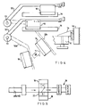
- a paper path for a proposed printer architecture 10 is illustrated in Fig. 1.
- the paper input and output features applicable to this invention are readily available standard components. The available options for paper input and output are quite broad.
- the illustration depicts a system which uses a roll feed input and a sheeter/stacker output 11. Paper proceeds generally from the left to the right in the press illustrated. Paper from the roll proceeds through the region where duplex printing and drying are accomplished. The details of the print head fixer/dryer region vary, depending on the desired capability of the particular press.
- a print engine comprises two towers 14, 16 of print modules 12 with a fixer/dryer region 20 situated between the towers 14 and 16.
- a print module 12 typically comprises adjustable print head mounts, rollers, and cue sensors.
- print heads 18 are accessible to the system operator.
- the print head mounts in the print module 12 could be rotated 90° about a vertical axis pivot on one side of the module 12, to provide the system operator print head access.
- the arrangement according to the present invention enables multi-color duplex printing in a very compact architecture, without requiring turnbars between print stations.
- finishing comprises various tasks, including but not limited to collecting the completed print work by rewinding it on a roll, cutting it into sheets or pages, stacking, folding, collating, etc.
- Fig. 2 there is illustrated a side view of an embodiment of an electronic print station having eight print modules 12.
- the print engine of Fig. 2 is comprised of eight print modules 12, it will be obvious to those skilled in the art that the number and arrangement of print modules may vary without departing from the scope of the present invention.
- the right hand stack of print modules is not needed if only one side of the substrate is being printed.
- the print stations comprise ink jet print stations in an ink jet system.
- the ink jet system may comprise a continuous ink jet system or a drop-on-demand ink jet system.
- the system could further comprise a continuous binary ink jet system having either a variable or a fixed number of drops per spot printed.
- the number of pixels per inch is preferably at least eighty.
- the maximum number of drops printed per spot is typically between one and sixty-four.
- the ink jet system comprises a duplex full process color printing system. Although the process speed is typically at least fifty feet per minute, the speed could be slower, such as for a drop-on-demand system.
- Fig. 3 is an illustration of two print modules 12 printing on opposite sides of substrate 22.
- the substrate 22 enters from the top left of Fig. 3, as indicated by arrow 30, and is wrapped around rollers 32 which provide a positive wrap around roller 34.
- the positive wrap provides a fixed position for printing.
- an eighteen inch print swath is to be created with the use of two nine inch print heads.
- This approach provides modularity in width. If the required print width is only, for example, nine inches, only one print head is required at each print station.
- the print head over roller 34 is spatially closer to the viewer than the print head over roller 36, which is further from the viewer. Print heads which are physically wider than their print swaths are staggered so that their print swaths butt (stitch), allowing the desired eighteen inch total print swath.
- roller 38 touches the opposite side of the web from the unfixed image.
- the bottom, or print side, of the web is heated, and the image in fixed.
- the web now proceeds to rollers 42 and 44, where an image is placed on the opposite side of the web from the image placed at the earlier print stations at rollers 34 and 36. The result is a duplex image created without a turnbar.
- the web now passes through the dryer area 20 again, and the unfixed image on the bottom of the web is fixed.
- FIG. 3 there is right side module 12 comprising two print heads 18 over rollers 34 and 36.
- the right side module 12 is identical to or the mirror image of left side module 12, comprising two print heads 18 over rollers 42 and 44.
- the dryers 40 are the same as dryers 50.
- the dryers 40 and 50 are themselves modular. The means for drying is positioned so that heat from the dryer does not affect print mechanisms. In the configuration illustrated, there are two dryers.
- the lower throughput device could use one module in its dryer, while the higher throughput device could use two modules, side by side.
- the dryers could be modular in width, so that, for example, a nine inch print width could use a single dryer, while the comparable eighteen inch print width would use two dryer modules, each drying half the print width.
- FIG. 3 Another level of modularity comprises the entire single color print system illustrated in Fig. 3. This system occurs at four positions in Fig. 2, to make up a four color duplex printer. In that context, it should be observed in Fig. 3 that the web enters the dryer area at the top left at the same angle as the web exits at the lower right.
- print modules such as printing two colors on a front side of the substrate and one color on a back side, or three colors on a front side and two on a back side, or one color on a front side and three colors on a back side, etc.
- a further feature of the print system illustrated in Fig. 3 is that opposite pairs of print heads 18 are at the same vertical height. This enables simpler maintenance and also allows for a stackable module. If a fifth print station is required for a particular system, it can be added to the system in a straightforward manner, without lengthening the digital printer. It is also possible, with the present invention, to add a second tower to provide fifth and/or sixth color capability, although this, of course, would lengthen the system.
- Fig. 4 there is illustrated a top view of the mounting of the print heads 18, showing how multiple print heads, specifically two print heads, are used to cover the total printed width.
- print heads 18 are accessible to the system operator.
- the print head mounts in the print module 12 can be rotated by 90° about vertical axis pivot points 51 and 53 on one side of the module 12, to provide the system operator print head access.
- the print head which prints on the left side of the web is placed over roller 36, and is attached to swing arm 50.
- the right side of swing arm 50 is detachably fixed to a stop 55, typically located on the right side of the printing system.
- swing arm 50 In the detached position, swing arm 50 assumes a position 50a at which the print head is serviceable by an operator. Similarly, swing arm 52 can swing about the pivot point 53 to assume the position 52a illustrated. This enables print head service by approaching the print head from the perspective 58.
- 55 illustrates an exploded view of the attachment point of either swing arm 50 or 52.
- a knurled screw 60 is shown as the means of attachment, but it is clear to one skilled in the art, that other quick detachment means could be used.
- the attachment means attaches the bar 50 (or 52) to a stop 54 which is slidably attached to a member 56 which is fixed to the frame of the electronic printing system. Movement of the stop 54 relative to the fixed member 56 by suitable adjusting means (not shown) creates a small change in the angle of the swing arm 50 (or 52).
- the system which mounts the print head 18 to the swing arm also allows significant adjustment in the "y" axis illustrated in Fig. 4 so that the print swaths of the print heads on rollers 34 and 36 can be perfectly aligned with one another.
- the mounting means also allows some degree of motion in the "x" direction, so that the print heads can be positioned properly with relation to the rollers 34 and 36. This latter adjustment is especially important because adjustment of the swing arm attachment point 54 also causes some motion of the print head in the "x" direction as a result of the alignment of the print head and roller axes.
- the entire print system comprising module 12, fixer/dryer region 20, and tower 16, can optionally be rotated 90° by means of one turnbar at the top of unit 20 and one turnbar at the bottom of unit 20.
- the print modules 12 can face aisles on either side of the web flow, enabling viewing and print head access, as well as shortening the length of the overall system.
- the present invention is useful in the field of electronic printing, and has the advantages of improving the architecture of an electronic printer so that modular solutions to various printing problems can be obtained. It is another advantage of the present invention that it provides a duplex color printing system which does not grow in length as more printing colors are required. It is a further advantage of the present invention that the modular system can be field upgraded from one color to multiple colors, and from simplex to duplex printing without adding proportional length to the printing system. It is a further advantage of the invention that it enables a modular upgrade path from page wide printing to two-up printing. It is another advantage of this invention that it provides an architecture which positions the fixer/dryers such that they are consolidated in a single cabinet and separated from, and specifically not under, the electronic printing system.
Abstract
Description
- This is a continuation-in-part of application Serial No. 08/543,944 filed on October 17, 1995.
- The present invention relates to electronic printing systems and, more particularly, to the architecture of high speed web presses for electronic printing.
- Electronic printing includes all ink jet printing, such as continuous ink jet printing, and all other systems wherein images are dried to fix the image on the substrate, as well as ionography, electrophotography, and all other systems wherein toner is fused to fix the image on the substrate. Current large scale electronic printing presses, typified by the Scitex 3500/3600 family, manufactured by Scitex Digital Printing, Inc., of Dayton, Ohio, are configured with a standard fuser/fixer or fixer/dryer system and are capable of drying at high speed, and full width.
- The design of a typical fixer/dryer is very much related to the designs of fixers in general use in the printing industry. Typically, dryers are purchased as standard configurations, which are available with few options. They can be used at lower power if they are to be used at low speed, but standard products are generally not modular in the sense to be described below.
- Conventional printing presses arrange all the apparatus for printing in a tower. Paper is fed to the tower by appropriate paper feeding apparatus using either sheets of paper, or a continuous web of paper. Typical color printing presses utilize multiple "towers". The paper is fed sequentially from one tower to the next, each tower printing a particular color (or sometimes a transparent coating). For printing processes which require fixing of one color ink before the next color ink is printed, a standard fixer/dryer is used between towers.
- When it is desired to print on both sides of a substrate, there are several options in common usage. In one common web press configuration the first side is printed in a first tower and then a second tower is used for printing on the reverse side. In this type configuration, a turnbar is required between towers. A turnbar is an arrangement of rollers which have the effect of inverting the web so that the unprinted side of the paper is available for printing in a subsequent tower. Typically, at least four colors are needed on each side of the paper, so eight towers are required. Obviously, the result is a long printing press, especially if dryers are required between print impressions. Long printing presses have associated problems which include excessive floor space requirements and, for digital printing systems, excessive data memory requirements.
- Another common web configuration is called a "perfecting" press. In this configuration, print stations are positioned on each side of the web, so that both sides of the substrate are printed essentially simultaneously. This helps the floor space requirements, but the press setup is complicated by the dense packing of the equipment.
- Furthermore, when printing at high speeds with ink jet presses, a roller is needed on the unprinted side of the substrate to hold the web flat and close to the print head, and the "wet" side of the substrate cannot be contacted immediately after printing. Therefore, a perfecting press design is not possible.
- It is seen, then that there is a need for an improved electronic printing architecture which overcomes the problems associated with prior art electronic printing system architectures, and, in particular, does not add substantially to the length of the printing system.
- This need is met by the present invention which discloses a modular ink jet printer architecture wherein printers are allowed to be constructed from modules which can be upgraded for increased number of colors, increased capability in speed, simplex/duplex and print width, and which enables compact, cost effective systems.
- In accordance with one aspect of the present invention, an electronic printing system includes substrate supply means, and means for controllably transporting the substrate through the printing system past a plurality of print stations in sequence. Each of the print stations are capable of printing on one side of the substrate. The system further comprises means for fixing the printed image between image stations without contacting the printed side until it is dry, and means for collecting the completed print work by rewinding the work on a roll, cutting the work into pages and stacking it, or any other suitable finishing operations. Print heads are mounted on a swing arm mechanism to allow rotation from a print-ready position into a service position. The system is created from simplex print modules and is capable of multi-color duplex printing without turnbars between print stations or print modules. The system is configured so that additional print stations can be added to the printing system without adding substantially to the length of the system.
- It is an object of the present invention to improve the architecture of an electronic printer so that modular solutions to various printing problems can be obtained. It is another object of the present invention to provide a duplex color printing system which does not grow in length as more printing colors are required. It is a further object of the present invention to provide a modular system which can be field upgraded from one color to multiple colors, and from simplex to duplex printing without adding proportional length to the printing system. It is yet another object of the invention to enable a modular upgrade path from page wide printing to two-up printing. It is still another object of this invention to provide an architecture in which the fixer/dryer is in a position separated from, and specifically not under, the electronic printing system. This has the advantage of insuring that the electronic print system is not affected by heat from the fixer/dryer. It is a further object of this invention to enable modular growth in drying capability as process speed increases. The present invention, therefore, provides the advantage of consolidating the dryers into a single modular unit to lower cost and enable improved management of the heat. The present invention provides the further advantage of enabling use of a single exhaust for air flow and a single insulated cabinet.
- Other objects and advantages of the invention will be apparent from the following description and the appended claims.
-
- Fig. 1 illustrates a paper path for the proposed printer architecture;
- Fig. 2 is a side view of one embodiment of an electronic print station having eight print modules;
- Fig. 3 illustrates an electronic print station wherein two print modules print on opposite sides of a substrate;
- Fig. 4 illustrates a top view of the full width print head mounting system for one station; and
- Fig. 5 illustrates a top view of the swing arm embodiment of the present invention wherein the entire print system is allowed to rotate by at least 90°.
- The present invention is described in detail with particular reference to certain preferred embodiments thereof, but it will be understood that modifications and variations can be effected without departing from the spirit and scope of the invention.
- Referring to the drawings, a paper path for a proposed
printer architecture 10 is illustrated in Fig. 1. The paper input and output features applicable to this invention are readily available standard components. The available options for paper input and output are quite broad. For exemplary purposes, the illustration depicts a system which uses a roll feed input and a sheeter/stacker output 11. Paper proceeds generally from the left to the right in the press illustrated. Paper from the roll proceeds through the region where duplex printing and drying are accomplished. The details of the print head fixer/dryer region vary, depending on the desired capability of the particular press. - In general, a print engine comprises two
towers print modules 12 with a fixer/dryer region 20 situated between thetowers print module 12 typically comprises adjustable print head mounts, rollers, and cue sensors. In accordance with the present invention,print heads 18 are accessible to the system operator. The print head mounts in theprint module 12 could be rotated 90° about a vertical axis pivot on one side of themodule 12, to provide the system operator print head access. The arrangement according to the present invention enables multi-color duplex printing in a very compact architecture, without requiring turnbars between print stations. - After a
substrate 22 from web feed 24 emerges from the printing and drying area, it moves into a finishingregion 26. As known by those skilled in the art, finishing comprises various tasks, including but not limited to collecting the completed print work by rewinding it on a roll, cutting it into sheets or pages, stacking, folding, collating, etc. - Referring now to Fig. 2, there is illustrated a side view of an embodiment of an electronic print station having eight
print modules 12. Although the print engine of Fig. 2 is comprised of eightprint modules 12, it will be obvious to those skilled in the art that the number and arrangement of print modules may vary without departing from the scope of the present invention. Of course, as will be understood by persons skilled in the art, the right hand stack of print modules is not needed if only one side of the substrate is being printed. - In a preferred embodiment of the present invention, the print stations comprise ink jet print stations in an ink jet system. The ink jet system may comprise a continuous ink jet system or a drop-on-demand ink jet system. The system could further comprise a continuous binary ink jet system having either a variable or a fixed number of drops per spot printed. The number of pixels per inch is preferably at least eighty. The maximum number of drops printed per spot is typically between one and sixty-four. In a further preferred embodiment, the ink jet system comprises a duplex full process color printing system. Although the process speed is typically at least fifty feet per minute, the speed could be slower, such as for a drop-on-demand system.
- Fig. 3 is an illustration of two
print modules 12 printing on opposite sides ofsubstrate 22. Thesubstrate 22 enters from the top left of Fig. 3, as indicated by arrow 30, and is wrapped around rollers 32 which provide a positive wrap aroundroller 34. The positive wrap provides a fixed position for printing. In the configuration shown in Fig. 3, there are four print heads 18. For the purposes of this illustration, but not to be considered as limiting the invention, it is assumed that an eighteen inch print swath is to be created with the use of two nine inch print heads. This approach provides modularity in width. If the required print width is only, for example, nine inches, only one print head is required at each print station. The print head overroller 34 is spatially closer to the viewer than the print head overroller 36, which is further from the viewer. Print heads which are physically wider than their print swaths are staggered so that their print swaths butt (stitch), allowing the desired eighteen inch total print swath. - Again, for illustration purposes only, it is assumed that the print heads 18 print down.
Roller 38 touches the opposite side of the web from the unfixed image. As the web proceeds through the fixingregion 40, the bottom, or print side, of the web is heated, and the image in fixed. The web now proceeds torollers rollers dryer area 20 again, and the unfixed image on the bottom of the web is fixed. - Several features of the approach of the present invention are apparent from Fig. 3. First, there is
right side module 12 comprising twoprint heads 18 overrollers right side module 12 is identical to or the mirror image ofleft side module 12, comprising twoprint heads 18 overrollers dryers 40 are the same asdryers 50. Thedryers - Another level of modularity comprises the entire single color print system illustrated in Fig. 3. This system occurs at four positions in Fig. 2, to make up a four color duplex printer. In that context, it should be observed in Fig. 3 that the web enters the dryer area at the top left at the same angle as the web exits at the lower right. Of course, those skilled in the art will recognize that there are many variations of print options achieved by combining print modules, such as printing two colors on a front side of the substrate and one color on a back side, or three colors on a front side and two on a back side, or one color on a front side and three colors on a back side, etc.
- A further feature of the print system illustrated in Fig. 3 is that opposite pairs of print heads 18 are at the same vertical height. This enables simpler maintenance and also allows for a stackable module. If a fifth print station is required for a particular system, it can be added to the system in a straightforward manner, without lengthening the digital printer. It is also possible, with the present invention, to add a second tower to provide fifth and/or sixth color capability, although this, of course, would lengthen the system.
- Referring now to Fig. 4, and continuing with Fig. 3, there is illustrated a top view of the mounting of the print heads 18, showing how multiple print heads, specifically two print heads, are used to cover the total printed width. In accordance with the present invention, print heads 18 are accessible to the system operator. The print head mounts in the
print module 12 can be rotated by 90° about vertical axis pivot points 51 and 53 on one side of themodule 12, to provide the system operator print head access. The print head which prints on the left side of the web is placed overroller 36, and is attached to swingarm 50. The right side ofswing arm 50 is detachably fixed to astop 55, typically located on the right side of the printing system. In the detached position,swing arm 50 assumes aposition 50a at which the print head is serviceable by an operator. Similarly, swing arm 52 can swing about thepivot point 53 to assume theposition 52a illustrated. This enables print head service by approaching the print head from theperspective 58. - Referring again to Fig. 4, 55 illustrates an exploded view of the attachment point of either
swing arm 50 or 52. For exemplary purposes a knurled screw 60 is shown as the means of attachment, but it is clear to one skilled in the art, that other quick detachment means could be used. The attachment means attaches the bar 50 (or 52) to astop 54 which is slidably attached to amember 56 which is fixed to the frame of the electronic printing system. Movement of thestop 54 relative to the fixedmember 56 by suitable adjusting means (not shown) creates a small change in the angle of the swing arm 50 (or 52). This changes the angle of theprint head 18 relative to the axis of the roller 36 (or 34) and allows perfect alignment of the axis of the print head to the printing mechanism axis. The system which mounts theprint head 18 to the swing arm also allows significant adjustment in the "y" axis illustrated in Fig. 4 so that the print swaths of the print heads onrollers rollers arm attachment point 54 also causes some motion of the print head in the "x" direction as a result of the alignment of the print head and roller axes. - In a preferred embodiment of the present invention, shown in Fig. 5, the entire print system, comprising
module 12, fixer/dryer region 20, andtower 16, can optionally be rotated 90° by means of one turnbar at the top ofunit 20 and one turnbar at the bottom ofunit 20. Thus, theprint modules 12 can face aisles on either side of the web flow, enabling viewing and print head access, as well as shortening the length of the overall system. - The present invention is useful in the field of electronic printing, and has the advantages of improving the architecture of an electronic printer so that modular solutions to various printing problems can be obtained. It is another advantage of the present invention that it provides a duplex color printing system which does not grow in length as more printing colors are required. It is a further advantage of the present invention that the modular system can be field upgraded from one color to multiple colors, and from simplex to duplex printing without adding proportional length to the printing system. It is a further advantage of the invention that it enables a modular upgrade path from page wide printing to two-up printing. It is another advantage of this invention that it provides an architecture which positions the fixer/dryers such that they are consolidated in a single cabinet and separated from, and specifically not under, the electronic printing system. This has the advantage of insuring that the electronic print system is not affected by heat from the fixer/dryer. It is another advantage of this invention that print head mounting on a swing arm allows accurate alignment of the printing axis and the paper motion, and additionally allows easily accessible print head servicing. It is yet another advantage of this invention that it enables modular growth in drying capability as process speed increases.
- The invention has been described in detail with particular reference to certain preferred embodiments thereof, but it will be understood that modifications and variations can be effected within the spirit and scope of the invention.
Claims (10)
- An electronic printing system comprising:at least one print heada swing arm mechanism to which the at least one print head is mountable, the swing arm mechanism allowing rotation of the at least one print head from a print-ready position into a service position;substrate supply means for supplying a substrate; andmeans for controllably transporting the substrate through the electronic printing system past the at least one print head to generate a printed image.
- An electronic printing system as claimed in claim 1 wherein configuration of the system enables the at least one print head to be placed in an approximately vertical alignment over the substrate.
- An electronic printing system as claimed in claim 1 further comprising a frame for defining structural rigidity of the electronic printing system.
- An electronic printing system as claimed in claim 3 further comprising a mounting means for mounting the swing arm to the frame of the printing system.
- An electronic printing system as claimed in claim 4 wherein the mounting means comprises an easily detachable mounting means.
- An electronic printing system as claimed in claim 5 further comprising slidable attachment means for slidably attaching the mounting means to the frame, whereby the print head axis can be aligned to the printing system axis, utilizing the swing arm as a rotation means.
- An electronic printing system as claimed in claim 3 further comprising attachment means for attaching the at least one print head to the swing arm mechanism.
- An electronic printing system as claimed in claim 7 wherein the attachment means allows adjustment of the at least one print head in an "x" direction and in a "y" direction.
- An electronic printing system as claimed in claim 1 wherein the electronic printing system comprises a continuous ink jet system.
- An electronic printing system as claimed in claim 1 wherein the electronic printing system comprises a duplex full process color printing system.
Applications Claiming Priority (2)
| Application Number | Priority Date | Filing Date | Title |
|---|---|---|---|
| US66556296A | 1996-06-18 | 1996-06-18 | |
| US665562 | 1996-06-18 |
Publications (3)
| Publication Number | Publication Date |
|---|---|
| EP0813971A2 true EP0813971A2 (en) | 1997-12-29 |
| EP0813971A3 EP0813971A3 (en) | 1999-01-07 |
| EP0813971B1 EP0813971B1 (en) | 2001-10-10 |
Family
ID=24670614
Family Applications (1)
| Application Number | Title | Priority Date | Filing Date |
|---|---|---|---|
| EP97304186A Expired - Lifetime EP0813971B1 (en) | 1996-06-18 | 1997-06-16 | Modular electronic printer architecture |
Country Status (4)
| Country | Link |
|---|---|
| EP (1) | EP0813971B1 (en) |
| AU (1) | AU726906B2 (en) |
| CA (1) | CA2207841A1 (en) |
| DE (1) | DE69707204T2 (en) |
Cited By (16)
| Publication number | Priority date | Publication date | Assignee | Title |
|---|---|---|---|---|
| US6209454B1 (en) * | 1997-05-05 | 2001-04-03 | Koenig & Bauer Aktiengesellschaft | Multicolor rotogravure rotary press with first and second side printing towers |
| WO2001056802A1 (en) * | 2000-02-06 | 2001-08-09 | Indigo N.V. | Tandem printer and printing method |
| EP1184188A2 (en) * | 2000-09-05 | 2002-03-06 | Hewlett-Packard Company | Dual ink jet print carriage for web printing |
| EP1238813A1 (en) * | 2001-03-08 | 2002-09-11 | Agfa-Gevaert | An ink jet printer equipped for aligning the printheads |
| EP1238814A1 (en) * | 2001-03-08 | 2002-09-11 | Agfa-Gevaert | Ink-jet printer equipped for aligning the printheads |
| US6554398B2 (en) | 2001-03-08 | 2003-04-29 | Agfa-Gevaert | Ink-jet printer equipped for aligning the printheads |
| US6823786B1 (en) | 1999-11-07 | 2004-11-30 | Hewlett-Packard Indigo B.V. | Tandem printing system with fine paper-position correction |
| US6851672B1 (en) | 2000-04-18 | 2005-02-08 | Hewlett-Packard Indigo B.V. | Sheet transport position and jam monitor |
| GB2435242A (en) * | 2006-02-15 | 2007-08-22 | Markem Tech Ltd | Modular apparatus for performing a work operation on a patch |
| EP2082885A1 (en) * | 2008-01-25 | 2009-07-29 | Kabushiki Kaisha Tokyo Kikai Seisakusho | Continuous paper web duplex inkjet printing unit |
| SG155764A1 (en) * | 2000-09-13 | 2009-10-29 | Silverbrook Res Pty Ltd | Modular printer with ink drying means for print media |
| WO2010034375A1 (en) * | 2008-09-26 | 2010-04-01 | Khs Ag | Device for applying one multiple-pass print each to packaging containers |
| US8113650B2 (en) | 2000-09-15 | 2012-02-14 | Silverbrook Resesarch Pty Ltd | Printer having arcuate printhead |
| US20120224010A1 (en) * | 2011-03-04 | 2012-09-06 | Kasiske Jr W Charles | Printing method including web media moving apparatus |
| US20120224009A1 (en) * | 2011-03-04 | 2012-09-06 | Kasiske Jr W Charles | Printing system including web media moving apparatus |
| KR101193442B1 (en) | 2009-05-22 | 2012-10-24 | 한국기계연구원 | printing apparatus |
Families Citing this family (5)
| Publication number | Priority date | Publication date | Assignee | Title |
|---|---|---|---|---|
| SG155763A1 (en) * | 2000-09-13 | 2009-10-29 | Silverbrook Res Pty Ltd | Modular printer and printhead assembly therefore |
| DE102004018483B4 (en) * | 2004-04-14 | 2007-11-29 | Infineon Technologies Ag | Method of applying coatings to ribbon-like structures in semiconductor device fabrication and use of a device for applying coatings to ribbon-like structures |
| DE102010016856A1 (en) * | 2010-05-10 | 2011-11-10 | OCé PRINTING SYSTEMS GMBH | Printing device i.e. cyan, magenta, yellow and black color printing device, for reciprocal printing of paper web, has pressure module arranged on top surface of print material to print images on back side of material |
| CN103221217B (en) * | 2010-06-24 | 2015-01-28 | 惠普发展公司,有限责任合伙企业 | Web press and method of printing |
| US11034164B2 (en) | 2017-04-06 | 2021-06-15 | Hewlett-Packard Development Company, L.P. | Printing path that travels in different directions through dryer |
Citations (7)
| Publication number | Priority date | Publication date | Assignee | Title |
|---|---|---|---|---|
| JPS60206690A (en) * | 1984-03-30 | 1985-10-18 | Matsushita Electric Ind Co Ltd | Type printer |
| GB2159770A (en) * | 1984-03-10 | 1985-12-11 | Control Systems Ltd | Thermal printer |
| DE3616925A1 (en) * | 1985-10-04 | 1987-04-09 | Robotron Veb K | Device for pivoting a thermal print head onto and away from the platen |
| JPS6341159A (en) * | 1986-08-06 | 1988-02-22 | Fuji Xerox Co Ltd | Thermal head positioning mechanism of line scanning type thermal recording apparatus |
| JPH01226375A (en) * | 1988-03-08 | 1989-09-11 | Seiko Epson Corp | Support mechanism of thermal printing head |
| DE4219798A1 (en) * | 1992-06-17 | 1993-12-23 | Esselte Meto Int Gmbh | Thermal print head with mechanism for head access - has head mounted on lever arrangement with eccentric element turned to effect release |
| EP0711063A2 (en) * | 1994-11-02 | 1996-05-08 | Nur Advanced Technologies Ltd. | Apparatus and method for duplex printing |
-
1997
- 1997-06-16 DE DE69707204T patent/DE69707204T2/en not_active Expired - Lifetime
- 1997-06-16 EP EP97304186A patent/EP0813971B1/en not_active Expired - Lifetime
- 1997-06-17 AU AU24930/97A patent/AU726906B2/en not_active Ceased
- 1997-06-17 CA CA002207841A patent/CA2207841A1/en not_active Abandoned
Patent Citations (7)
| Publication number | Priority date | Publication date | Assignee | Title |
|---|---|---|---|---|
| GB2159770A (en) * | 1984-03-10 | 1985-12-11 | Control Systems Ltd | Thermal printer |
| JPS60206690A (en) * | 1984-03-30 | 1985-10-18 | Matsushita Electric Ind Co Ltd | Type printer |
| DE3616925A1 (en) * | 1985-10-04 | 1987-04-09 | Robotron Veb K | Device for pivoting a thermal print head onto and away from the platen |
| JPS6341159A (en) * | 1986-08-06 | 1988-02-22 | Fuji Xerox Co Ltd | Thermal head positioning mechanism of line scanning type thermal recording apparatus |
| JPH01226375A (en) * | 1988-03-08 | 1989-09-11 | Seiko Epson Corp | Support mechanism of thermal printing head |
| DE4219798A1 (en) * | 1992-06-17 | 1993-12-23 | Esselte Meto Int Gmbh | Thermal print head with mechanism for head access - has head mounted on lever arrangement with eccentric element turned to effect release |
| EP0711063A2 (en) * | 1994-11-02 | 1996-05-08 | Nur Advanced Technologies Ltd. | Apparatus and method for duplex printing |
Non-Patent Citations (3)
| Title |
|---|
| PATENT ABSTRACTS OF JAPAN vol. 010, no. 059 (M-459), 8 March 1986 & JP 60 206690 A (MATSUSHITA DENKI SANGYO KK), 18 October 1985 * |
| PATENT ABSTRACTS OF JAPAN vol. 012, no. 257 (M-719), 20 July 1988 & JP 63 041159 A (FUJI XEROX CO LTD), 22 February 1988 * |
| PATENT ABSTRACTS OF JAPAN vol. 013, no. 545 (M-902), 6 December 1989 & JP 01 226375 A (SEIKO EPSON CORP), 11 September 1989 * |
Cited By (26)
| Publication number | Priority date | Publication date | Assignee | Title |
|---|---|---|---|---|
| US6209454B1 (en) * | 1997-05-05 | 2001-04-03 | Koenig & Bauer Aktiengesellschaft | Multicolor rotogravure rotary press with first and second side printing towers |
| US6823786B1 (en) | 1999-11-07 | 2004-11-30 | Hewlett-Packard Indigo B.V. | Tandem printing system with fine paper-position correction |
| US6731898B1 (en) | 2000-02-06 | 2004-05-04 | Hewlett-Packard Indigo B.V. | Interleaved tandem printer and printing method |
| WO2001056802A1 (en) * | 2000-02-06 | 2001-08-09 | Indigo N.V. | Tandem printer and printing method |
| US6851672B1 (en) | 2000-04-18 | 2005-02-08 | Hewlett-Packard Indigo B.V. | Sheet transport position and jam monitor |
| EP1184188A3 (en) * | 2000-09-05 | 2002-06-05 | Hewlett-Packard Company | Dual ink jet print carriage for web printing |
| US6593953B1 (en) | 2000-09-05 | 2003-07-15 | Hewlett-Packard Development Company, L.P. | Dual ink jet print carriage for web printing |
| CN1298548C (en) * | 2000-09-05 | 2007-02-07 | 惠普公司 | Double-ink-jet printing carriage for network printing |
| EP1184188A2 (en) * | 2000-09-05 | 2002-03-06 | Hewlett-Packard Company | Dual ink jet print carriage for web printing |
| SG155764A1 (en) * | 2000-09-13 | 2009-10-29 | Silverbrook Res Pty Ltd | Modular printer with ink drying means for print media |
| US8113650B2 (en) | 2000-09-15 | 2012-02-14 | Silverbrook Resesarch Pty Ltd | Printer having arcuate printhead |
| US6554398B2 (en) | 2001-03-08 | 2003-04-29 | Agfa-Gevaert | Ink-jet printer equipped for aligning the printheads |
| EP1238814A1 (en) * | 2001-03-08 | 2002-09-11 | Agfa-Gevaert | Ink-jet printer equipped for aligning the printheads |
| EP1238813A1 (en) * | 2001-03-08 | 2002-09-11 | Agfa-Gevaert | An ink jet printer equipped for aligning the printheads |
| GB2435242A (en) * | 2006-02-15 | 2007-08-22 | Markem Tech Ltd | Modular apparatus for performing a work operation on a patch |
| EP2082885A1 (en) * | 2008-01-25 | 2009-07-29 | Kabushiki Kaisha Tokyo Kikai Seisakusho | Continuous paper web duplex inkjet printing unit |
| WO2010034375A1 (en) * | 2008-09-26 | 2010-04-01 | Khs Ag | Device for applying one multiple-pass print each to packaging containers |
| JP2012503576A (en) * | 2008-09-26 | 2012-02-09 | カーハーエス・ゲゼルシャフト・ミト・ベシュレンクテル・ハフツング | A device that performs one multiple printing on each packaging means |
| RU2472626C2 (en) * | 2008-09-26 | 2013-01-20 | Кхс Гмбх | Device for applying multiple printing on package |
| US8667895B2 (en) | 2008-09-26 | 2014-03-11 | Khs Gmbh | Device for applying one multiple-pass print each to packaging containers |
| CN102202902B (en) * | 2008-09-26 | 2014-07-16 | Khs有限责任公司 | Device for applying one multiple-pass print each to packaging containers |
| KR101193442B1 (en) | 2009-05-22 | 2012-10-24 | 한국기계연구원 | printing apparatus |
| US20120224010A1 (en) * | 2011-03-04 | 2012-09-06 | Kasiske Jr W Charles | Printing method including web media moving apparatus |
| US20120224009A1 (en) * | 2011-03-04 | 2012-09-06 | Kasiske Jr W Charles | Printing system including web media moving apparatus |
| US8303106B2 (en) * | 2011-03-04 | 2012-11-06 | Eastman Kodak Company | Printing system including web media moving apparatus |
| US8303107B2 (en) * | 2011-03-04 | 2012-11-06 | Eastman Kodak Company | Printing method including web media moving apparatus |
Also Published As
| Publication number | Publication date |
|---|---|
| AU2493097A (en) | 1998-01-08 |
| CA2207841A1 (en) | 1997-12-18 |
| EP0813971A3 (en) | 1999-01-07 |
| AU726906B2 (en) | 2000-11-23 |
| EP0813971B1 (en) | 2001-10-10 |
| DE69707204D1 (en) | 2001-11-15 |
| DE69707204T2 (en) | 2002-05-16 |
Similar Documents
| Publication | Publication Date | Title |
|---|---|---|
| EP0813971B1 (en) | Modular electronic printer architecture | |
| US6050191A (en) | System and method for providing multi-pass imaging in a printing system | |
| US6382850B1 (en) | Ink jet printer for photofinishing | |
| US6019046A (en) | Printing press with replaceable units allowing for different methods of printing | |
| EP0925948B1 (en) | Printer architecture | |
| EP0435520A2 (en) | Printing press and method | |
| US8737862B2 (en) | Operating a selectively interconnected modular printing system | |
| RU96119207A (en) | PRINT METHOD FOR PAPER TAPE, PRINTING SYSTEM | |
| US8240843B2 (en) | Media roll winder for digital web press | |
| US8967789B2 (en) | Spreader/transfix system for handling tabbed media sheets during duplex printing in an inkjet printer | |
| US6935738B2 (en) | Ink-jet printer and method for printing image material in an ink-jet printer | |
| US8625141B2 (en) | Configuring a modular printing system | |
| CA1321919C (en) | Printer apparatus having two-sided printing capability | |
| JPH11138915A (en) | Printer | |
| EP1063096A2 (en) | Ink jet printer for photofinishing | |
| US20150239234A1 (en) | System for reducing tension fluctuations on a web | |
| US20030230210A1 (en) | Rotary plural plate cylinders head | |
| US20150239231A1 (en) | Method for reducing artifacts using tension control | |
| US11528386B1 (en) | Printing color separation and fiducials on substrates in an inkjet printer to register and print remaning color separations | |
| US20240100825A1 (en) | System and method for improving image quality by orienting adjacent printheads to produce opposite direction ink flows in the manifolds of the adjacent printheads | |
| US6886459B2 (en) | Double-sided high speed printing apparatus and method | |
| US11827035B2 (en) | System and method for printing color images on substrates in an inkjet printer | |
| US20150239232A1 (en) | System for reducing artifacts using tension control | |
| US20150239233A1 (en) | Method for reducing tension fluctuations on a web | |
| JP2000025214A (en) | Left/right print synchronism shift detector for ink jet printer |
Legal Events
| Date | Code | Title | Description |
|---|---|---|---|
| PUAI | Public reference made under article 153(3) epc to a published international application that has entered the european phase |
Free format text: ORIGINAL CODE: 0009012 |
|
| AK | Designated contracting states |
Kind code of ref document: A2 Designated state(s): DE FR GB |
|
| 17P | Request for examination filed |
Effective date: 19971208 |
|
| PUAL | Search report despatched |
Free format text: ORIGINAL CODE: 0009013 |
|
| AK | Designated contracting states |
Kind code of ref document: A3 Designated state(s): AT BE CH DE DK ES FI FR GB GR IE IT LI LU MC NL PT SE |
|
| AKX | Designation fees paid |
Free format text: DE FR GB |
|
| 17Q | First examination report despatched |
Effective date: 20000114 |
|
| GRAG | Despatch of communication of intention to grant |
Free format text: ORIGINAL CODE: EPIDOS AGRA |
|
| GRAG | Despatch of communication of intention to grant |
Free format text: ORIGINAL CODE: EPIDOS AGRA |
|
| GRAH | Despatch of communication of intention to grant a patent |
Free format text: ORIGINAL CODE: EPIDOS IGRA |
|
| GRAH | Despatch of communication of intention to grant a patent |
Free format text: ORIGINAL CODE: EPIDOS IGRA |
|
| GRAH | Despatch of communication of intention to grant a patent |
Free format text: ORIGINAL CODE: EPIDOS IGRA |
|
| GRAA | (expected) grant |
Free format text: ORIGINAL CODE: 0009210 |
|
| AK | Designated contracting states |
Kind code of ref document: B1 Designated state(s): DE FR GB |
|
| REF | Corresponds to: |
Ref document number: 69707204 Country of ref document: DE Date of ref document: 20011115 |
|
| REG | Reference to a national code |
Ref country code: GB Ref legal event code: IF02 |
|
| ET | Fr: translation filed | ||
| PLBE | No opposition filed within time limit |
Free format text: ORIGINAL CODE: 0009261 |
|
| STAA | Information on the status of an ep patent application or granted ep patent |
Free format text: STATUS: NO OPPOSITION FILED WITHIN TIME LIMIT |
|
| 26N | No opposition filed | ||
| REG | Reference to a national code |
Ref country code: GB Ref legal event code: 732E |
|
| REG | Reference to a national code |
Ref country code: FR Ref legal event code: TP |
|
| PGFP | Annual fee paid to national office [announced via postgrant information from national office to epo] |
Ref country code: GB Payment date: 20050506 Year of fee payment: 9 |
|
| PGFP | Annual fee paid to national office [announced via postgrant information from national office to epo] |
Ref country code: FR Payment date: 20050602 Year of fee payment: 9 |
|
| PGFP | Annual fee paid to national office [announced via postgrant information from national office to epo] |
Ref country code: DE Payment date: 20050630 Year of fee payment: 9 |
|
| PG25 | Lapsed in a contracting state [announced via postgrant information from national office to epo] |
Ref country code: DE Free format text: LAPSE BECAUSE OF THE APPLICANT RENOUNCES Effective date: 20060221 |
|
| PG25 | Lapsed in a contracting state [announced via postgrant information from national office to epo] |
Ref country code: GB Free format text: LAPSE BECAUSE OF NON-PAYMENT OF DUE FEES Effective date: 20060616 |
|
| GBPC | Gb: european patent ceased through non-payment of renewal fee |
Effective date: 20060616 |
|
| REG | Reference to a national code |
Ref country code: FR Ref legal event code: ST Effective date: 20070228 |
|
| PG25 | Lapsed in a contracting state [announced via postgrant information from national office to epo] |
Ref country code: FR Free format text: LAPSE BECAUSE OF NON-PAYMENT OF DUE FEES Effective date: 20060630 |