EP0809981B1 - Biodegradable stent - Google Patents
Biodegradable stent Download PDFInfo
- Publication number
- EP0809981B1 EP0809981B1 EP97303112A EP97303112A EP0809981B1 EP 0809981 B1 EP0809981 B1 EP 0809981B1 EP 97303112 A EP97303112 A EP 97303112A EP 97303112 A EP97303112 A EP 97303112A EP 0809981 B1 EP0809981 B1 EP 0809981B1
- Authority
- EP
- European Patent Office
- Prior art keywords
- stent
- tube
- copolymer
- body lumen
- expandable
- Prior art date
- Legal status (The legal status is an assumption and is not a legal conclusion. Google has not performed a legal analysis and makes no representation as to the accuracy of the status listed.)
- Expired - Lifetime
Links
Images
Classifications
-
- A—HUMAN NECESSITIES
- A61—MEDICAL OR VETERINARY SCIENCE; HYGIENE
- A61F—FILTERS IMPLANTABLE INTO BLOOD VESSELS; PROSTHESES; DEVICES PROVIDING PATENCY TO, OR PREVENTING COLLAPSING OF, TUBULAR STRUCTURES OF THE BODY, e.g. STENTS; ORTHOPAEDIC, NURSING OR CONTRACEPTIVE DEVICES; FOMENTATION; TREATMENT OR PROTECTION OF EYES OR EARS; BANDAGES, DRESSINGS OR ABSORBENT PADS; FIRST-AID KITS
- A61F2/00—Filters implantable into blood vessels; Prostheses, i.e. artificial substitutes or replacements for parts of the body; Appliances for connecting them with the body; Devices providing patency to, or preventing collapsing of, tubular structures of the body, e.g. stents
- A61F2/82—Devices providing patency to, or preventing collapsing of, tubular structures of the body, e.g. stents
-
- A—HUMAN NECESSITIES
- A61—MEDICAL OR VETERINARY SCIENCE; HYGIENE
- A61F—FILTERS IMPLANTABLE INTO BLOOD VESSELS; PROSTHESES; DEVICES PROVIDING PATENCY TO, OR PREVENTING COLLAPSING OF, TUBULAR STRUCTURES OF THE BODY, e.g. STENTS; ORTHOPAEDIC, NURSING OR CONTRACEPTIVE DEVICES; FOMENTATION; TREATMENT OR PROTECTION OF EYES OR EARS; BANDAGES, DRESSINGS OR ABSORBENT PADS; FIRST-AID KITS
- A61F2210/00—Particular material properties of prostheses classified in groups A61F2/00 - A61F2/26 or A61F2/82 or A61F9/00 or A61F11/00 or subgroups thereof
- A61F2210/0004—Particular material properties of prostheses classified in groups A61F2/00 - A61F2/26 or A61F2/82 or A61F9/00 or A61F11/00 or subgroups thereof bioabsorbable
Definitions
- the present invention relates to a biodegradable stent that is capable of being absorbed by the human body, and that also may function as a drug or nutrient delivery system as a result of its biodegradable properties.
- Stents including cardiovascular and biliary stents
- a body lumen such as an artery, vein, biliary duct, or esophagus. They may be employed as a primary treatment for a constriction of a body lumen (stenosis), or may be used following a medical procedure, such as angioplasty, used to remedy stenosis.
- stents have taken two forms.
- Such stents are permanently implanted into the human body by deploying them on or through a catheter, although removable stents of this kind are known to the art.
- the stent which may be woven, strutted, or wound like a spring, is placed in tension or compression along the inner or outer perimeter of the catheter, and percutaneously inserted into the body where it is guided to the site of implantation.
- the stent then is released from the perimeter of the catheter, or extruded from the interior of the catheter, where it expands to a fixed, predetermined diameter, and is held in position as a result of that expansion.
- Many different configurations of such self-expanding stents, and of catheters used to deploy such stents, are known to the art.
- Kawai et al. United States Patent No. 4,950,258.
- Kawai discloses the use of a spring-like coil of plastic having "shape memory.”
- the stent is manufactured to a desired size from homopolymers or copolymers of lactide and/or glycolide, and then compressed under suitable conditions for insertion into the body. Thereafter, the stent is heated, and because of "shape memory,” returns to its original (uncompressed) size.
- a second type of stent commonly used in the field is expandable as a result of mechanical action by the surgeon.
- One such stent is disclosed in Palmaz, United Stated Patent Nos. 4,733,665, 4,776,337 and 4,639,632.
- an unexpanded stent is permanently implanted in the body by percutaneously inserting it into a vessel using a catheter, and guiding the stent to the site where it is to be permanently implanted.
- the balloon portion of the catheter is expanded, and concomitantly a portion of the stent also is expanded solely as a result of the mechanical force applied by the expanding balloon, until the stent is sized appropriately for the implantation site.
- the stents disclosed in Palmaz are made of a metal or a nondegradable plastic, and, to achieve compatibility with and in the body, the stent may be coated with a biologically-compatible substance.
- stents of the types described above exhibit undesirable characteristics that the art has sought to overcome.
- Self-expanding stents may be inappropriately sized for the sites where they are to be deployed, increasing the risk of rupture, stent migration, stenosis, and thrombosis as the stent continually tries to expand after deployment to its predetermined, optimal diameter.
- a stent sized too small for the lumen may project into the lumen, thereby causing a primary or secondary obstruction or migration.
- vascular smooth muscle cell migration and proliferation may be undesirable when it is uncontrolled (as in intimal hyperplasia) and results in the occlusion of the lumen that has been surgically opened by placement of the stent.
- stents such as that described by Palmaz may be undesirable when the risk of intimal hyperplasia is substantial.
- the benefits of a balloon-deployed stent therefore may not be realized in such circumstances.
- design of stents such as those described in Palmaz are dictated primarily by mechanical considerations, such as the forces needed to open the stent, biological considerations (such as designing the stent to limit cell ingrowth and migration, for example) frequently play a secondary role or no role at all.
- Still another disadvantage of existing stents is that the materials from which they are made are rigid, and therefore the compliance of the stents (i.e. , the ability to control the flexibility of the material used to design stents for particular applications) is limited. This has the disadvantage of exposing patients to risks associated with the placement of a device that may exhibit a rigidity in excess of that needed for the particular application.
- Most conventional stents also are capable of being used as drug delivery systems when they are coated with a biodegradable coating that contains the drug to be delivered.
- Beck et al. United States Patent No. 5,147,385, discloses the use of a degradable, mechanically expandable stent prepared from poly( ⁇ -caprolactone) or similar polymers that melt between 45-75°C, because the melted polymer may be expanded in such a manner as to adapt to the body lumen in which it is deployed.
- poly( ⁇ -caprolactone) enters a liquid phase in the temperature range that Beck discloses (at about 60°C)
- the ability to achieve controlled, improved strength characteristics using the stent described by Beck is limited.
- the temperature range described by Beck et al. is well-above the glass-transition temperature for poly( ⁇ -caprolactone).
- WO 93/15787 (Chandler) describes a stent made of a biodegradable copolymer which may be applied to the exterior surface of an angioplasty balloon. Upon being positioned at a restricted vessel section, a contrast fluid present in the balloon is heated which results in the stent being heated. Heating the stent and expanding the angioplasty balloon allows the stent to expand so that it presses against the vessel wall. The balloon is then collapsed.
- the polymer stent is preferably formed of two polymers comprising a lactide and a caprolactone.
- EP-A-0,420,541 (Bristol-Myers Squibb Company) describes a biodegradable, biocompatible, resorbable ureteral stent made of a biodegradable polymer composition having a defined tensile strength, a defined elongation and a Shaw hardness of between 50 to 100.
- the polymer composition preferably comprises a terpolymer of L(-)lactide, glycolide and epsiloncaprolactone.
- EP-A-0,621,017 (Advanced Cardiovascular Systems, Inc.) describes an intravascular stent comprising a cylindrical sheet having interlocking overlapping edges.
- the stent may be expanded by a balloon catheter or it may be self-expanding.
- the stent is biocompatible and is capable of localised drug delivery. It is described that the stent may be made of materials including polymers of the linear aliphatic polyester and glycolide families.
- WO 95/29647 (Scimed Life Systems, Inc.) describes a stent which has collagen applied to it for increasing the biocompatibility of the stent.
- EP-A-0,716,836 (Advanced Cardiovascular Systems, Inc.) describes a stent having a planar sheet of polymeric material attached to the outside of the expandable stent structural member.
- the polymeric material is preferably bioabsorbable and may be loaded or coated with a therapeutic agent or drug.
- Slepian et al. United States Patent No. 5,213,580, discloses an endoluminal sealing process using a poly(caprolactone) material that is flowable at temperatures above 60-80°C. According to Slepian, this flowable material is able to conform to irregularities on the inner surface of the body lumen in which it is deployed.
- Goldberg et al. United States Patent No. 5,085,629, discloses the manufacture of a urethral stent made from a terpolymer of L-lactide, glycolide, and ⁇ -caprolactone, which is selected to permit the stent to degrade within the body. Goldberg does not, however, disclose the use of an expandable stent, nor does Goldberg et al. provide any information regarding the design of the stent or its method of deployment within the body.
- a stent that overcomes the problems just identified, while at the same time providing or enhancing the benefits that result from the use of stents, is needed to improve patient safety and recovery.
- the present invention seeks to overcome those problems by providing an expandable, biodegradable stent for use within a body lumen.
- the invention consists in essence of a hollow tube made from a copolymer of L-lactide and ⁇ -caprolactone that, in unexpanded form, is of a first diameter sufficient to be retained upon a balloon catheter for placement within the body lumen.
- the stent is not expandable at normal body temperatures.
- the stent is expandable using a thermally-assisted mechanical expansion process at a temperature between about 38-55°C, to a second diameter sufficiently large to be retained in place within the body lumen. It is a characteristic feature of the present invention that the tube has a non-woven structure.
- the invention also is found in a method of making that stent.
- Another object of the invention is to provide a stent that can be designed with a variable geometry and compliance to permit the designer and/or surgeon to tailor the characteristics of a particular stent to fit its application more precisely than is presently possible.
- Still another object of the invention is to provide such a stent made from a material that permits the use of the stent as a drug delivery system to promote healing at the site of deployment.
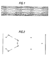
- Figure 1 is an illustration of an embodiment of an unexpanded stent according to the present invention.
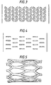
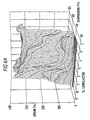
- Figures 2-4 are plan drawings of various perforation patterns useful for stents made according to the invention.
- Figure 5 is an illustration of the end portion of the stent of Figure 1 after expansion.
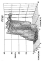
- Figures 6A and 6B are graphs showing the relationship between caprolactone content in the copolymer of the present invention, temperature, and strain.
- the stent made according to the present invention comprises a cylindrical tube of appropriate size to be inserted into a body lumen, and thus typically is about 1-12 cm in length (and for vascular applications, most frequently 2-3 cm in length), and about 0.5-8 mm in diameter (for vascular stents, most frequently 1-3 mm in diameter).
- the stent is a hollow tube of substantial length that is used to line the body lumen and provide support for keeping the lumen open, while at the same time limiting intimal hyperplasia by providing a finite number of perforations through which cells may migrate and occlude the body lumen in the region of the stent.
- This technique which includes endoluminal paving, therefore is believed to be effective in limiting intimal hyperplasia.
- Endothelial coverage in which the cells grow over and envelop the stent, is desirable in some cases because the stent may become a site for thrombosis, or clotting, to occur. As a result, it may be desirable to permit limited cell growth from the intima into the stent by providing perforations in the walls of the stent through which endothelial cells may grow and eventually cover all of the stent.
- the stent made according to the present invention may desirably incorporate perforations of different size and shape to permit the ingrowth of cells from the intima
- a small perforation is provided in the walls of the stent at discrete intervals (designated by the letter "a") correlated to cell ingrowth in the particular body lumen.
- a vascular stent having the design shown in Figure 2 would be perforated at 2 mm intervals to accommodate cell ingrowth from the vascular intima, which has been shown to grow over this distance.
- Figures 3 and 4 show perforation patterns that have been found desirable for expanding the stent intraluminally while maintaining significant hoop strength.
- the stent may be an imperforate tube.
- Perforations in the walls of a stent made according to the present invention reduce the amount of material that must be heated to permanently deploy the stent. As a result, those perforations permit the stent to be deployed with a lesser amount of heat than if the stent were not perforated. This means that a perforated stent can be deployed using lower temperature heating devices, or with less heating time, or both, than if perforations were not present.
- the stent still must be heated near or above the glass-transition temperature, as described below, to be expanded.
- the size and shape of these perforations, the frequency of their placement along the walls of the stent, and the thickness of the stent material also control the total force required to expand the stent, and also to resist collapse after deployment.
- the characteristics of the perforations also affect the change in length of the stent as it is expanded.
- such perforations may be placed to accomplish desirable biological effects, such as control ingrowth or migration, at distances that maximize the ability to prevent lumen narrowing, and that also foster cell ingrowth for the particular body lumen.
- the design thus may be selected to optimize the mechanical properties required of the stent with the biological properties that are desired from the stent.
- a radio-opaque contrast material is incorporated into the stent, so that the location of the stent can be determined using conventional radiographic techniques.
- the radio-opaque material may take the form of a platinum wire or other similar radio-opaque structure that is molded into the stent or inserted through perforations in the stent.
- the radio-opaque material may take the form of fine particles of barium sulfate that are blended with the copolymer from which the stent is made; in this case, the radio-opaque material must not adversely impact the mechanical properties of the copolymer, and must be biocompatible.
- the stent of the present invention is prepared from a copolymer of L-lactide and ⁇ -caprolactone in the molar ratios described below.
- blends of either this copolymer (with different quantities of L-lactide and ⁇ -caprolactone in each component of the blend) or of each homopolymer also may be used to achieve the desired thermal and mechanical properties in the final product.
- the L-lactide- ⁇ -caprolactone copolymer is biodegradable, in that it is broken down over time by random hydrolysis within the body and metabolized without adverse consequence to the patient.
- the relative amounts of each of L-lactide and ⁇ -caprolactone in the copolymer are selected to produce thermal and mechanical properties that permit the copolymer to be thermo-mechanically expanded just above normal body temperatures, while remaining sufficiently rigid and strong at normal body temperatures to support the body lumen.
- the copolymer when heated, should be expandable near its glass-transition temperature, in the range of about 38-55 °C, but the copolymer should not melt ( viz ., become a flowable liquid) within the temperature range.
- thermo-mechanical “expansion” means that the polymer can be plastically deformed without fracture by increasing the inside and outside diameters of the stent under applied heat and mechanical force.
- the copolymer undergoes a transition from a glassy state, in which the copolymer is strong and stiff, and exhibits less than about 3% elongation, to a rubbery state in which the material becomes elastic, leathery, pliable, and undergoes more than about 200% elongation.
- the temperature needed to expand the copolymer is significantly higher than 55°C, the heat needed to expand the copolymer may adversely affect the surrounding tissue by burning or otherwise damaging it, thereby interfering with healing following the deployment of the stent.
- the expansion temperature of the polymer is below about 38°C, there is a risk that the stent will soften in the body and collapse if the temperature rises as a result of fever or other similar circumstance. This creates a risk of restenosis or other adverse conditions resulting from collapse or deformation of the softened stent.
- the data set forth in Table 1 were obtained by performing tensile testing in a controlled temperature environment using thin samples (approximately 0.3 mm x 6.35 mm x 75 mm) of the L-lactide/ ⁇ -caprolactone copolymer.
- the strain and elastic modulus data presented are averages obtained from multiple tests of each material at each temperature. Melting point data were either determined by conventional DSC techniques or modulated DSC techniques (as denoted in Table 1 by an asterisk).
- Figure 6 shows the effects of material composition and temperature on the strain of each of the materials tested. From the data plotted in Figures 6A and 6B, it can be seen that the material softens beginning at just above the body temperature (around 38°C), and that pronounced strain effects can be noted in the copolymer beginning around 40°C. For the reasons noted above, the preferred copolymers exhibit the desired softening behavior beginning at a slightly higher temperature, around 43°C. The figures also reveal that softening occurs at lower temperatures in stents having a higher ⁇ -caprolactone content.
- copolymers having about 3-7 mol % ⁇ -caprolactone exhibit a substantial improvement in elongation up to temperatures of about 55°C.
- copolymers containing up to about 10 mol % ⁇ -caprolactone can be utilized in the invention.
- biodegradable materials including copolymers of L-lactide and/or ⁇ -caprolactone, that exhibit similar properties also may be used in the present invention without departing therefrom.
- the temperature of the polymer can be increased incrementally to a point near the glass-transition temperature of the copolymer, permitting the stent to enter a rubbery phase that takes advantage of a lower elastic modulus.
- the stent may be plastically deformed and the shape stabilized prior to any viscoelastic behavior (such as creep, stress relaxation, strain recovery, or shrinkage) causes the stent to return to its unexpanded shape or to diminish in strength.
- any viscoelastic behavior such as creep, stress relaxation, strain recovery, or shrinkage
- thermo-mechanical expansion of the stent is considered a processing step occurring in situ and concomitant with deployment.
- Thermo-mechanical expansion can be viewed as a low temperature drawing of the copolymer tube, which orients the polymer chains and crystallites circumferentially. It is believed that this expansion method, used within the temperature range of about 38-55°C, results in the preferential orientation of the polymer chains in the amorphous domains of the material.
- This low temperature drawing substantially increases the elastic modulus and strength of the stent, while stabilizing and maintaining the shape of the expanded stent under external loads.
- the degree of improvement of these properties depends on the draw ratio, measured as a function of the cross-sectional area of the annulus defining the end of the stent prior to and after expansion.
- the draw ratio should be above about 1.2, and preferably above about 2.0, and depends on the deployment method and material properties such as initial crystallinity and composition. Desirable draw ratios desired for any particular material can be readily determined by those skilled in
- the copolymer used in the present invention may be obtained from Purac Biochem b.v. (Gorinchem, Netherlands) in the nominal ratios specified above. However, because of the presence of unreacted monomers, low molecular weight oligomers, catalysts, and other impurities, it is desirable (and, depending upon the materials used, may be necessary) to increase the purity of the copolymer over that which is commercially available. This purification process yields a copolymer of better-known composition, and therefore increases both the predictability of the mechanical characteristics of the stents made from such materials and the reliability of those stents. In the purification process, the copolymer is dissolved in a suitable solvent, such as methylene chloride.
- a suitable solvent such as methylene chloride.
- Suitable solvents include (but are not limited to) ethyl acetate, chloroform, and tetrahydrofuran.
- the copolymer solution is mixed with a second material that is miscible with the solvent, but in which the copolymer is not soluble, so that the copolymer (but not appreciable quantities of impurities or unreacted monomer) precipitates out of solution.
- a methylene chloride solution of the copolymer may be mixed with heptane, causing the copolymer to fall out of solution.
- the solvent mixture then is removed from the copolymer precipitate using conventional techniques.
- the copolymer thus prepared is melted at a temperature sufficiently low to minimize polymer degradation in a conventional extruder, and extruded through a die to form a cylindrical tube of the desired wall thickness, inside and outside diameters.
- the stent may be cut to length on line while hot, or preferably is cooled before cutting.
- the molten extrudate is cooled preferably by quenching in air or in a temperature-controlled water bath to retain shape and strength-enhancing molecular orientation (along the long axis of the tube) that is introduced by the extrusion process.
- the extrusion and quenching processes also are used to control the degree of crystallinity of the extruded tube, by locking in the amorphous structure of the extruded polymer, thereby reducing the glass-transition temperature to fall within the desired range.
- the copolymers are nearly amorphous and have oriented molecular chains.
- the stents prepared in this way may be employed in the form in which they were extruded without further processing (i.e., a solid, unperforated tube), or they may incorporate perforations of such size, shape, and frequency so as to enhance thermally-assisted mechanical expansion and allow regeneration of the vascular (or other) tissue.
- the perforations may be machined using excimer or other lasers, for example, a 193 nanometer argon fluoride laser which is particularly useful to take advantage of certain absorption properties of the L-lactide- ⁇ -caprolactone copolymer.
- the laser pulses preferably at 40Hz and 100 mJ/pulse, dispersing energy at 0.7 J/cm 2 .
- the invention therefore does not rely upon a woven material to define perforations, which is an advantage because woven material potentially provides a site for thrombogenesis and bacteria colonization.
- deployment of woven polymer stents may be elusive, since polymers typically creep during the time when they are stored in a stressed position on the catheter.
- the stents may be injection molded using conventional techniques, or may be formed using dip-coating techniques.
- any desired perforations may be part of the mold or substrate for coating, or may be micromachined as described above.
- the orientation of the polymer chains and crystallites circumferentially, to improve the mechanical properties of the stent, is important.
- Conventional methods of processing do not allow circumferential orientation of polymer chains and crystal domains (i.e ., crystallites).
- One method to achieve this preferred orientation is to use a glass rod with a crystal-like film of poly(tetrafluoroethylene) (PTFE) deposited mechanically on the surface by known methods.
- the PTFE film should be deposited circumferentially on a glass rod having an outer diameter equivalent to the desired inner diameter of the stent.
- the copolymer from which the stent is made is dip coated onto the rod from either the melt or an appropriate solution, such as ethyl acetate or methylene chloride.
- the formed tube may be heat treated to increase its crystallinity; for example, the tube may be heated at about 80-100°C for about 5 minutes.
- the crystallinity should remain low enough to allow low temperature expansion of the stent.
- the fabrication process is believed to orient both the polymer chains and any crystallites formed in the circumferential direction.
- the "oriented" tube may be processed by laser micromachining as described previously. The thermo-mechanical expansion process further increases the crystallinity, modulus, and strength of the material, and ultimately the strength of the stent.
- Still another method for creating materials with oriented polymer chains and crystallites is to fabricate tubes from fibers drawn from the materials described herein.
- Conventional drawing of fibers aligns the polymer chains and induced crystallites parallel to the direction of fiber length. This process can result in substantial increases in modulus and strength as compared with the non-oriented material.
- fibers for this application would be processed with draw ratios of approximately 20 to 50% of the draw ratio that produced optimal strength and modulus. Fibers of this nature will achieve their optimal strength and modulus when they are expanded in situ , where they will receive the additional drawing.
- fibers may be fabricated into a tube by conventional fiber winding techniques on appropriately sized mandrels, and bonded to make contiguous structures by either solvent vapor fusion, autoclave pressure, vacuum bag, or other conventional techniques.
- This phase of the processing should not alter the orientation of either the polymer chains or crystallites in the drawn fibers. It is believed that the fibers should be oriented circumferentially so the polymer molecular chains and crystallites are aligned in a similar fashion.
- the formed tube may be heat treated to increase the crystallinity; for example, the tube may be heated at about 80-100°C for about 5 minutes. However, the crystallinity should remain low enough to allow expansion of the stent.
- micromachining then may be performed to introduce any desired perforations.
- the stent desirably may incorporate one or more drugs that positively affect healing at the site where the stent is deployed, either incorporated into the copolymer forming the stent, or incorporated into the coating, or both.
- drugs may include antithrombotics (such as anticoagulants), antimitogens, antimitotoxins, antisense oligonucleotides, gene therapy vehicles, nitric oxide, and growth factors and inhibitors.
- Direct thrombin inhibitors believed to be useful in the invention include Hirudin, Hirugen, Hirulog, PPACK (D-phenylalanyl-L-propyl-L-arginine chloromethyl ketone), Argatreban, and D-FPRCH 2 Cl (D-phenylalanyl-L-propyl-L-arginyl chloromethyl ketone); indirect thrombin inhibitors include Heparin and Warfarin. Materials capable of ⁇ -particle emission also may be useful to inhibit neointima formation. These materials preferably are incorporated in quantities that permit desirable timed release as the stent and/or coating biodegrades.
- a stent such as that shown in Figure 1 is believed to have a useful structural life of about 5-10 weeks, and remains in the body for about 6-9 months without showing major loss of structure. From this information, the quantities of drugs to be included in the copolymer matrix may be readily determined.
- a stent prepared according to the present invention preferably also incorporates surface coatings or thin films (about 25 ⁇ m thick) designed to reduce the risk of thrombosis and to deliver bioactive agents.
- These include polymers such as poly(ethylene glycol), poly(vinyl alcohol), poly(vinyl pyrrolidone), poly(methacrylic acid), poly(acrylic acid), and polyacrylamide, that are blended or copolymerized with biodegradable materials; monomers of those materials also may be employed, as may other materials having similar lubricious effects.
- These materials may be formed as either statistical, block, or graft copolymers or as interpenetrating polymer networks. These materials may serve as drug delivery systems by incorporating effective quantities of pharmacologically active materials in the coating.
- the film may coat only the surfaces of the stent, or may extend over the micro-machined perforations in the stent to create a combination of a barrier and delivery vehicle.
- stents In making stents according to the invention, it is desirable to control the glass-transition temperature by controlling the copolymer molar ratio and degree of crystallinity. Thus, a stent having lower crystallinity will exhibit a lower glass-transition temperature than with a stent having a higher degree of crystallinity.
- degree of crystallinity By controlling the degree of crystallinity, therefore, one may engineer a copolymer that exhibits optimal strain performance within the temperature range above body temperature but below temperatures that will injure tissue surrounding the body lumen in which the stent is to be deployed.
- quenching the extruded hot stent tends to lock in an amorphous structure that desirably reduces the glass-transition temperature of the polymer.
- the stents made according to the invention may be annealed at about 80-90°C to increase the crystallinity of the polymer and thereby increase the glass-transition temperature.
- the poly(L-lactide- ⁇ -caprolactone) copolymer undergoes thermally-assisted mechanical expansion when exposed to a balloon catheter that is heated in situ during percutaneous insertion of the stent.
- a conventional balloon catheter used for percutaneous placement of a stent may be filled with a heated contrast medium (at a temperature sufficiently high to heat the stent) that can be injected into the balloon, providing in one medium a method both for expanding the balloon and for transferring heat into the stent.
- the contrast medium may be heated in situ using microwave radiation, an RF generator, or a resistance heater, and/or by injecting into the catheter contrast medium that has been heated externally of the body.
- the contrast medium will need to be heated to about 70°C to permit sufficient heat to transfer to the stent, and the heated medium will be retained within or circulated through the catheter over a predetermined time period to permit the temperature of the stent to rise above the glass-transition temperature. Heated contrast medium is retained within or circulated through the catheter until the stent rises above the glass-transition temperature.
- Experimental data shows that sufficient heating occurs in a 37°C water bath using a saline solution in place of a contrast medium, holding the saline solution at 60°C for about three minutes.
- a perfusion catheter may be used so that the flow of fluids, such as blood, through the body lumen is not interrupted while the stent is being deployed.
- the perfusion catheter by permitting blood flow through the affected region, also enhances convection cooling of the catheter and stent.
- the stent is placed in its unexpanded state along the periphery of a balloon portion of a balloon catheter, and inserted into the body lumen percutaneously where it travels through the body lumen to the desired site for deployment.
- the location of the stent at the desired site may be confirmed intraoperatively by radiography.
- the stent is heated for the requisite period of time until its temperature is above the glass-transition temperature of the copolymer, and the balloon then is expanded so that the stent expands to the required size.
- the heat source then is removed, and the stent cooled by convection and conduction until its temperature is reduced below the glass-transition temperature.
- a cooling medium may optionally be introduced through the catheter to cool the stent below the glass-transition temperature.
- the stent may also be expanded slightly during this cooling process to fix the circumferential alignment of the polymer chains and prevent strain recovery (shrinkage) of the expanded stent.
- microwave energy first heats low water content materials, leaving high water content materials (such as body tissue) relatively unaffected. Because the stent made according to the invention is made from a low water content material, it will be heated preferentially by such a microwave antenna before body tissues are adversely affected. If such a heating technique is used, it may be desirable to modify the stent to include material enhancing the stent's absorption of microwave radiation.
- the microwave frequency and power may be adjusted to preferentially heat the amorphous domains and disordered defects within the crystalline domains.
- the selective heating may be achieved by using an alternating current field with a high frequency in the microwave region (e.g. , 2.45 GHz, 1.5 kW) in a manner known to the art.
- the advantage of this method of heating is that low temperature microwave heat-drawing is believed to produce similar physical properties at lower temperatures than the other methods described herein, since the amorphous domains are selectively targeted.
- it is believed that the expansion observed within the temperature range of about 38-55°C is due to the orientation of the polymer chains in the amorphous domains. This method is believed to allow deployment with minimal transfer of heat to the surrounding tissue, and avoids the need for positive cooling.
- Another embodiment uses a balloon that is coated with a microwave sensitive material that selectively heats when exposed to microwave radiation. Heat transferred from this coating raises the temperature of the stent to permit thermo-mechanical expansion.
- the balloon may be coated with a dye or similar substance that heats upon exposure to electromagnetic radiation (such as ultraviolet light), which is introduced through the catheter using an optical fiber to heat the stent in situ .
- electromagnetic radiation such as ultraviolet light
- thermo-mechanical deployment techniques reveal that other heating and expansion methods besides those described may be used to carry out the invention. In practice, however, it should be understood that the invention is limited to thermo-mechanical deployment techniques.
Abstract
Description
- The present invention relates to a biodegradable stent that is capable of being absorbed by the human body, and that also may function as a drug or nutrient delivery system as a result of its biodegradable properties.
- Stents, including cardiovascular and biliary stents, are well-known as devices that are used to support a body lumen, such as an artery, vein, biliary duct, or esophagus. They may be employed as a primary treatment for a constriction of a body lumen (stenosis), or may be used following a medical procedure, such as angioplasty, used to remedy stenosis.
- Conventional stents have taken two forms. First, there are the self-expanding stents that typically are made of metal, and that may include a biocompatible coating. Such stents are permanently implanted into the human body by deploying them on or through a catheter, although removable stents of this kind are known to the art. The stent, which may be woven, strutted, or wound like a spring, is placed in tension or compression along the inner or outer perimeter of the catheter, and percutaneously inserted into the body where it is guided to the site of implantation. The stent then is released from the perimeter of the catheter, or extruded from the interior of the catheter, where it expands to a fixed, predetermined diameter, and is held in position as a result of that expansion. Many different configurations of such self-expanding stents, and of catheters used to deploy such stents, are known to the art.
- One variation on these self-expanding stents is illustrated in Kawai et al., United States Patent No. 4,950,258. Kawai discloses the use of a spring-like coil of plastic having "shape memory." The stent is manufactured to a desired size from homopolymers or copolymers of lactide and/or glycolide, and then compressed under suitable conditions for insertion into the body. Thereafter, the stent is heated, and because of "shape memory," returns to its original (uncompressed) size.
- A second type of stent commonly used in the field is expandable as a result of mechanical action by the surgeon. One such stent is disclosed in Palmaz, United Stated Patent Nos. 4,733,665, 4,776,337 and 4,639,632. According to the Palmaz patents, an unexpanded stent is permanently implanted in the body by percutaneously inserting it into a vessel using a catheter, and guiding the stent to the site where it is to be permanently implanted. Upon reaching the site of implantation, the balloon portion of the catheter is expanded, and concomitantly a portion of the stent also is expanded solely as a result of the mechanical force applied by the expanding balloon, until the stent is sized appropriately for the implantation site. Thereafter, the expanded balloon is deflated, and the catheter is removed from the body, leaving the stent held permanently in position. The stents disclosed in Palmaz are made of a metal or a nondegradable plastic, and, to achieve compatibility with and in the body, the stent may be coated with a biologically-compatible substance.
- Commercially available stents of the types described above exhibit undesirable characteristics that the art has sought to overcome. Self-expanding stents may be inappropriately sized for the sites where they are to be deployed, increasing the risk of rupture, stent migration, stenosis, and thrombosis as the stent continually tries to expand after deployment to its predetermined, optimal diameter. Conversely, a stent sized too small for the lumen may project into the lumen, thereby causing a primary or secondary obstruction or migration. Both self-expanding and expandable stents that are known in the art, because they are designed for permanent implantation in the body, increase the risk of restenosis, thrombosis or other adverse medical effects because of the risk of adverse reaction by surrounding tissue, adverse reaction by the material flowing through the body lumen (such as blood or blood products), and deterioration of surrounding tissue and/or the stent itself. The metals or alloys used for such stents, because they are believed to be biologically stable, also remain in the body for the patient's life, unless surgically removed at a later date along with surrounding tissue. Thus, these stents do not permit temporary placement within the body unless patient and surgeon are prepared to undertake a second procedure to remove the stent, which is difficult or impossible in most cases.
- Conventional balloon-deployed stents, like that described by Palmaz, also require an extensively perforated structure that can be mechanically expanded intraluminally by a balloon catheter without applying forces that are potentially threatening to the surrounding tissue. Such perforations also permit cell growth to occur from the intima or media lining the lumen. Thus, for example, endothelial cells and smooth muscle fibroblasts migrate through the perforations inside and around stents like that shown in Palmaz. Such endothelial cell growth is desirable to the extent that the endothelial layer inhibits the formation of blood clots (thrombogenesis) by providing a blood-compatible surface. However, vascular smooth muscle cell migration and proliferation may be undesirable when it is uncontrolled (as in intimal hyperplasia) and results in the occlusion of the lumen that has been surgically opened by placement of the stent. Thus, stents such as that described by Palmaz may be undesirable when the risk of intimal hyperplasia is substantial. The benefits of a balloon-deployed stent therefore may not be realized in such circumstances. Moreover, to the extent that the design of stents such as those described in Palmaz are dictated primarily by mechanical considerations, such as the forces needed to open the stent, biological considerations (such as designing the stent to limit cell ingrowth and migration, for example) frequently play a secondary role or no role at all.
- Still another disadvantage of existing stents is that the materials from which they are made are rigid, and therefore the compliance of the stents (i.e., the ability to control the flexibility of the material used to design stents for particular applications) is limited. This has the disadvantage of exposing patients to risks associated with the placement of a device that may exhibit a rigidity in excess of that needed for the particular application.
- Most conventional stents also are capable of being used as drug delivery systems when they are coated with a biodegradable coating that contains the drug to be delivered. The amount of the drug that can be delivered, and the time over which it may be released, therefore may be limited by the quantity of coating employed.
- Beck et al., United States Patent No. 5,147,385, discloses the use of a degradable, mechanically expandable stent prepared from poly(ε-caprolactone) or similar polymers that melt between 45-75°C, because the melted polymer may be expanded in such a manner as to adapt to the body lumen in which it is deployed. At the same time, because poly(ε-caprolactone) enters a liquid phase in the temperature range that Beck discloses (at about 60°C), the ability to achieve controlled, improved strength characteristics using the stent described by Beck is limited. Furthermore, the temperature range described by Beck et al. is well-above the glass-transition temperature for poly(ε-caprolactone). This limits the ability of a stent made according to Beck et al. to resist radially compressive forces imparted by the lumen upon the stent without creeping or relaxing, introducing a substantial risk of occluding the lumen. Alternatively, one might use massive structures made according to Beck et al. to keep the lumen open, but in so doing, the normal function of the lumen would be perturbed significantly, possibly creating regions where flow of body liquids through the lumen would be severely restricted or stagnate, so that clots may form in those regions.
- WO 93/15787 (Chandler) describes a stent made of a biodegradable copolymer which may be applied to the exterior surface of an angioplasty balloon. Upon being positioned at a restricted vessel section, a contrast fluid present in the balloon is heated which results in the stent being heated. Heating the stent and expanding the angioplasty balloon allows the stent to expand so that it presses against the vessel wall. The balloon is then collapsed. The polymer stent is preferably formed of two polymers comprising a lactide and a caprolactone.
- EP-A-0,420,541 (Bristol-Myers Squibb Company) describes a biodegradable, biocompatible, resorbable ureteral stent made of a biodegradable polymer composition having a defined tensile strength, a defined elongation and a Shaw hardness of between 50 to 100. The polymer composition preferably comprises a terpolymer of L(-)lactide, glycolide and epsiloncaprolactone.
- EP-A-0,621,017 (Advanced Cardiovascular Systems, Inc.) describes an intravascular stent comprising a cylindrical sheet having interlocking overlapping edges. The stent may be expanded by a balloon catheter or it may be self-expanding. The stent is biocompatible and is capable of localised drug delivery. It is described that the stent may be made of materials including polymers of the linear aliphatic polyester and glycolide families.
- WO 95/29647 (Scimed Life Systems, Inc.) describes a stent which has collagen applied to it for increasing the biocompatibility of the stent.
- EP-A-0,716,836 (Advanced Cardiovascular Systems, Inc.) describes a stent having a planar sheet of polymeric material attached to the outside of the expandable stent structural member. The polymeric material is preferably bioabsorbable and may be loaded or coated with a therapeutic agent or drug.
- Slepian et al., United States Patent No. 5,213,580, discloses an endoluminal sealing process using a poly(caprolactone) material that is flowable at temperatures above 60-80°C. According to Slepian, this flowable material is able to conform to irregularities on the inner surface of the body lumen in which it is deployed.
- Goldberg et al., United States Patent No. 5,085,629, discloses the manufacture of a urethral stent made from a terpolymer of L-lactide, glycolide, and ε-caprolactone, which is selected to permit the stent to degrade within the body. Goldberg does not, however, disclose the use of an expandable stent, nor does Goldberg et al. provide any information regarding the design of the stent or its method of deployment within the body.
- Thus, a stent that overcomes the problems just identified, while at the same time providing or enhancing the benefits that result from the use of stents, is needed to improve patient safety and recovery.
- The present invention seeks to overcome those problems by providing an expandable, biodegradable stent for use within a body lumen. The invention consists in essence of a hollow tube made from a copolymer of L-lactide and ε-caprolactone that, in unexpanded form, is of a first diameter sufficient to be retained upon a balloon catheter for placement within the body lumen. The stent is not expandable at normal body temperatures. The stent is expandable using a thermally-assisted mechanical expansion process at a temperature between about 38-55°C, to a second diameter sufficiently large to be retained in place within the body lumen. It is a characteristic feature of the present invention that the tube has a non-woven structure. The invention also is found in a method of making that stent.
- It is thus an object of the invention to provide a biodegradable stent that can be deployed in the body for a sufficient period of time to permit the site to be supported by the stent to heal, remodel, and grow strong, and thereafter to be absorbed into the body, thus reducing the risk of thrombosis or other adverse health effects associated with foreign materials in the body.
- It is still another object of the invention to provide such a stent which can be deployed percutaneously by taking advantage of thermally-activated properties that permit the stent to be permanently deformed at temperatures just above normal body temperature, while remaining sufficiently rigid at body temperature to provide for mechanical support of the surrounding tissue.
- Another object of the invention is to provide a stent that can be designed with a variable geometry and compliance to permit the designer and/or surgeon to tailor the characteristics of a particular stent to fit its application more precisely than is presently possible.
- Still another object of the invention is to provide such a stent made from a material that permits the use of the stent as a drug delivery system to promote healing at the site of deployment. These and other objects of the invention are achieved as described below.
- Figure 1 is an illustration of an embodiment of an unexpanded stent according to the present invention. Figures 2-4 are plan drawings of various perforation patterns useful for stents made according to the invention. Figure 5 is an illustration of the end portion of the stent of Figure 1 after expansion.
- Figures 6A and 6B are graphs showing the relationship between caprolactone content in the copolymer of the present invention, temperature, and strain.
- The stent made according to the present invention comprises a cylindrical tube of appropriate size to be inserted into a body lumen, and thus typically is about 1-12 cm in length (and for vascular applications, most frequently 2-3 cm in length), and about 0.5-8 mm in diameter (for vascular stents, most frequently 1-3 mm in diameter). As shown in Figure 1, the stent is a hollow tube of substantial length that is used to line the body lumen and provide support for keeping the lumen open, while at the same time limiting intimal hyperplasia by providing a finite number of perforations through which cells may migrate and occlude the body lumen in the region of the stent. This technique, which includes endoluminal paving, therefore is believed to be effective in limiting intimal hyperplasia.
- Endothelial coverage, in which the cells grow over and envelop the stent, is desirable in some cases because the stent may become a site for thrombosis, or clotting, to occur. As a result, it may be desirable to permit limited cell growth from the intima into the stent by providing perforations in the walls of the stent through which endothelial cells may grow and eventually cover all of the stent. Thus, as shown in Figures 2 through 4, the stent made according to the present invention may desirably incorporate perforations of different size and shape to permit the ingrowth of cells from the intima In Figure 2, a small perforation is provided in the walls of the stent at discrete intervals (designated by the letter "a") correlated to cell ingrowth in the particular body lumen. For example, a vascular stent having the design shown in Figure 2 would be perforated at 2 mm intervals to accommodate cell ingrowth from the vascular intima, which has been shown to grow over this distance.
- Figures 3 and 4 show perforation patterns that have been found desirable for expanding the stent intraluminally while maintaining significant hoop strength. Alternatively, the stent may be an imperforate tube.
- Perforations in the walls of a stent made according to the present invention reduce the amount of material that must be heated to permanently deploy the stent. As a result, those perforations permit the stent to be deployed with a lesser amount of heat than if the stent were not perforated. This means that a perforated stent can be deployed using lower temperature heating devices, or with less heating time, or both, than if perforations were not present. (The stent still must be heated near or above the glass-transition temperature, as described below, to be expanded.) The size and shape of these perforations, the frequency of their placement along the walls of the stent, and the thickness of the stent material also control the total force required to expand the stent, and also to resist collapse after deployment. The characteristics of the perforations also affect the change in length of the stent as it is expanded. Finally, such perforations may be placed to accomplish desirable biological effects, such as control ingrowth or migration, at distances that maximize the ability to prevent lumen narrowing, and that also foster cell ingrowth for the particular body lumen. The design thus may be selected to optimize the mechanical properties required of the stent with the biological properties that are desired from the stent.
- In a particularly preferred embodiment of the invention, a radio-opaque contrast material is incorporated into the stent, so that the location of the stent can be determined using conventional radiographic techniques. The radio-opaque material may take the form of a platinum wire or other similar radio-opaque structure that is molded into the stent or inserted through perforations in the stent. Alternatively, the radio-opaque material may take the form of fine particles of barium sulfate that are blended with the copolymer from which the stent is made; in this case, the radio-opaque material must not adversely impact the mechanical properties of the copolymer, and must be biocompatible.
- When the stent is expanded, any perforations that are included in the stent also are expanded, and their shape is changed. This is illustrated in Figure 5, which is an expanded version of the stent depicted in Figure 1.
- Regardless of the macrostructure of the stent, the stent of the present invention is prepared from a copolymer of L-lactide and ε-caprolactone in the molar ratios described below. In addition to the random copolymer, blends of either this copolymer (with different quantities of L-lactide and ε-caprolactone in each component of the blend) or of each homopolymer also may be used to achieve the desired thermal and mechanical properties in the final product. The L-lactide-ε-caprolactone copolymer is biodegradable, in that it is broken down over time by random hydrolysis within the body and metabolized without adverse consequence to the patient.
- The relative amounts of each of L-lactide and ε-caprolactone in the copolymer are selected to produce thermal and mechanical properties that permit the copolymer to be thermo-mechanically expanded just above normal body temperatures, while remaining sufficiently rigid and strong at normal body temperatures to support the body lumen. Thus, when heated, the copolymer should be expandable near its glass-transition temperature, in the range of about 38-55 °C, but the copolymer should not melt (viz., become a flowable liquid) within the temperature range. (The exact glass-transition temperature will vary depending upon the relative composition of each component of the copolymer and other physical properties of the material.) In this context, thermo-mechanical "expansion" means that the polymer can be plastically deformed without fracture by increasing the inside and outside diameters of the stent under applied heat and mechanical force. Thus, in the useful temperature range, the copolymer undergoes a transition from a glassy state, in which the copolymer is strong and stiff, and exhibits less than about 3% elongation, to a rubbery state in which the material becomes elastic, leathery, pliable, and undergoes more than about 200% elongation. It is believed that if the temperature needed to expand the copolymer is significantly higher than 55°C, the heat needed to expand the copolymer may adversely affect the surrounding tissue by burning or otherwise damaging it, thereby interfering with healing following the deployment of the stent. At the same time, however, if the expansion temperature of the polymer is below about 38°C, there is a risk that the stent will soften in the body and collapse if the temperature rises as a result of fever or other similar circumstance. This creates a risk of restenosis or other adverse conditions resulting from collapse or deformation of the softened stent.
- Some mechanical properties of the poly(L-lactide-ε-caprolactone) copolymer are set forth in Table 1. Thus, it is believed copolymers having a molar ratio of L-lactide to ε-caprolactone of about 90:10 to about 98:2 (as determined by conventional NMR analysis) are useful in the present invention.
L-lactide (mol %) ε-caprolactone (mol %) Melting Point (°C) Sample Temper- ature (°C) Modulus of Elasticity (MPa) Strain (%) 86 14 130-140 35 1134 372 37 878 335 40 818 347.3 42 338 368.7 45 148 382.5 47 136 384 50 17 411.3 53 -- 393.2 91 9 141-165 35 1916 2.8 37 1690 2.8 40 1809 115 42 1432 151.7 45 758 375.2 47 1051 356.7 50 352 381.7 53 121 383.3 92 8 152-171 35 1309 3 37 910 2.9 40 1225 88.1 42 1451 192.5 45 591 318.7 47 991 340.7 50 499 324.3 93 7 155.5* 35 1035 3.07 37 1147 3.58 40 1233 2.9 42 1013 6.14 45 1290 41.3 47 1367 222 50 1343 264 53 529 294 93.5 6.5 155-172 35 1421 2.3 37 1262 2.5 40 1274 3 42 1559 3 45 1036 3.9 47 1051 308.7 50 543 335.7 53 550 291.7 93.7 6.3 151.52* -35 1064 2.68 37 1006 2.55 40 937 2.95 42 1104 2.73 45 1751 38.35 47 1128 292 50 787 326 53 324 319 95.6 4.4 155.44* 35 1471 2.68 37 865 2.75 40 788 2.83 42 835 2.75 45 916 74.00 47 1192 194.00 50 934 320.00 53 779 330.00 55 1572 297.00 97 3 156-178 35 1656 2.4 37 1155 3.2 40 1191 2.6 42 1305 3.3 45 1054 3.7 47 1537 3.4 50 1085 302 53 1467 270.3 97.0 3.0 166.24* 35 1628 2.53 37 1141 3.16 40 1120 2.98 42 1003 3.30 45 921 3.18 47 980 74.00 50 1019 356.00 53 903 342.00 55 713 318.00 - The data set forth in Table 1 were obtained by performing tensile testing in a controlled temperature environment using thin samples (approximately 0.3 mm x 6.35 mm x 75 mm) of the L-lactide/ε-caprolactone copolymer. The strain and elastic modulus data presented are averages obtained from multiple tests of each material at each temperature. Melting point data were either determined by conventional DSC techniques or modulated DSC techniques (as denoted in Table 1 by an asterisk).
- Figure 6 shows the effects of material composition and temperature on the strain of each of the materials tested. From the data plotted in Figures 6A and 6B, it can be seen that the material softens beginning at just above the body temperature (around 38°C), and that pronounced strain effects can be noted in the copolymer beginning around 40°C. For the reasons noted above, the preferred copolymers exhibit the desired softening behavior beginning at a slightly higher temperature, around 43°C. The figures also reveal that softening occurs at lower temperatures in stents having a higher ε-caprolactone content. Thus, as shown in Figures 6A and 6B, at just above body temperature, copolymers having about 3-7 mol % ε-caprolactone exhibit a substantial improvement in elongation up to temperatures of about 55°C. However, it should be understood that copolymers containing up to about 10 mol % ε-caprolactone can be utilized in the invention.
- Other biodegradable materials, including copolymers of L-lactide and/or ε-caprolactone, that exhibit similar properties also may be used in the present invention without departing therefrom.
- Using the heating techniques described more fully below, the temperature of the polymer can be increased incrementally to a point near the glass-transition temperature of the copolymer, permitting the stent to enter a rubbery phase that takes advantage of a lower elastic modulus. In this phase, the stent may be plastically deformed and the shape stabilized prior to any viscoelastic behavior (such as creep, stress relaxation, strain recovery, or shrinkage) causes the stent to return to its unexpanded shape or to diminish in strength. Following expansion, the polymer is allowed to cool, but because plastic deformation has occurred, the stent remains open. Attempting to expand the stent of the present invention below the glass-transition temperature causes the stent to fracture as a result of its brittle or glassy characteristics below the glass-transition temperature. This could be potentially hazardous, depending upon whether and how the stent fractures as a result of being expanded improperly. Thus, controlled heating and expansion of the stent is important to the invention, as it results in a circumferential drawing of the extruded stent, helping to orient the copolymer molecules, and thereby enhances the modulus and strength of the materials, and ultimately the strength of the stent.
- The thermo-mechanical expansion of the stent is considered a processing step occurring in situ and concomitant with deployment. Thermo-mechanical expansion can be viewed as a low temperature drawing of the copolymer tube, which orients the polymer chains and crystallites circumferentially. It is believed that this expansion method, used within the temperature range of about 38-55°C, results in the preferential orientation of the polymer chains in the amorphous domains of the material. This low temperature drawing substantially increases the elastic modulus and strength of the stent, while stabilizing and maintaining the shape of the expanded stent under external loads. The degree of improvement of these properties depends on the draw ratio, measured as a function of the cross-sectional area of the annulus defining the end of the stent prior to and after expansion. The draw ratio should be above about 1.2, and preferably above about 2.0, and depends on the deployment method and material properties such as initial crystallinity and composition. Desirable draw ratios desired for any particular material can be readily determined by those skilled in the art.
- The copolymer used in the present invention may be obtained from Purac Biochem b.v. (Gorinchem, Netherlands) in the nominal ratios specified above. However, because of the presence of unreacted monomers, low molecular weight oligomers, catalysts, and other impurities, it is desirable (and, depending upon the materials used, may be necessary) to increase the purity of the copolymer over that which is commercially available. This purification process yields a copolymer of better-known composition, and therefore increases both the predictability of the mechanical characteristics of the stents made from such materials and the reliability of those stents. In the purification process, the copolymer is dissolved in a suitable solvent, such as methylene chloride. Other suitable solvents include (but are not limited to) ethyl acetate, chloroform, and tetrahydrofuran. The copolymer solution is mixed with a second material that is miscible with the solvent, but in which the copolymer is not soluble, so that the copolymer (but not appreciable quantities of impurities or unreacted monomer) precipitates out of solution. For example, a methylene chloride solution of the copolymer may be mixed with heptane, causing the copolymer to fall out of solution. The solvent mixture then is removed from the copolymer precipitate using conventional techniques.
- To form the stent, the copolymer thus prepared is melted at a temperature sufficiently low to minimize polymer degradation in a conventional extruder, and extruded through a die to form a cylindrical tube of the desired wall thickness, inside and outside diameters. The stent may be cut to length on line while hot, or preferably is cooled before cutting. The molten extrudate is cooled preferably by quenching in air or in a temperature-controlled water bath to retain shape and strength-enhancing molecular orientation (along the long axis of the tube) that is introduced by the extrusion process. The extrusion and quenching processes also are used to control the degree of crystallinity of the extruded tube, by locking in the amorphous structure of the extruded polymer, thereby reducing the glass-transition temperature to fall within the desired range. Thus, after the extrusion process, the copolymers are nearly amorphous and have oriented molecular chains.
- The stents prepared in this way may be employed in the form in which they were extruded without further processing (i.e., a solid, unperforated tube), or they may incorporate perforations of such size, shape, and frequency so as to enhance thermally-assisted mechanical expansion and allow regeneration of the vascular (or other) tissue. The perforations may be machined using excimer or other lasers, for example, a 193 nanometer argon fluoride laser which is particularly useful to take advantage of certain absorption properties of the L-lactide-ε-caprolactone copolymer. The laser pulses preferably at 40Hz and 100 mJ/pulse, dispersing energy at 0.7 J/cm2. The invention therefore does not rely upon a woven material to define perforations, which is an advantage because woven material potentially provides a site for thrombogenesis and bacteria colonization. In addition, deployment of woven polymer stents may be elusive, since polymers typically creep during the time when they are stored in a stressed position on the catheter.
- As a alternative to the extrusion process just described, the stents may be injection molded using conventional techniques, or may be formed using dip-coating techniques. In these embodiments, any desired perforations may be part of the mold or substrate for coating, or may be micromachined as described above.
- The orientation of the polymer chains and crystallites circumferentially, to improve the mechanical properties of the stent, is important. Conventional methods of processing do not allow circumferential orientation of polymer chains and crystal domains (i.e., crystallites). One method to achieve this preferred orientation is to use a glass rod with a crystal-like film of poly(tetrafluoroethylene) (PTFE) deposited mechanically on the surface by known methods. The PTFE film should be deposited circumferentially on a glass rod having an outer diameter equivalent to the desired inner diameter of the stent. The copolymer from which the stent is made is dip coated onto the rod from either the melt or an appropriate solution, such as ethyl acetate or methylene chloride. Additionally, the formed tube may be heat treated to increase its crystallinity; for example, the tube may be heated at about 80-100°C for about 5 minutes. However, the crystallinity should remain low enough to allow low temperature expansion of the stent. The fabrication process is believed to orient both the polymer chains and any crystallites formed in the circumferential direction. The "oriented" tube may be processed by laser micromachining as described previously. The thermo-mechanical expansion process further increases the crystallinity, modulus, and strength of the material, and ultimately the strength of the stent.
- Still another method for creating materials with oriented polymer chains and crystallites is to fabricate tubes from fibers drawn from the materials described herein. Conventional drawing of fibers aligns the polymer chains and induced crystallites parallel to the direction of fiber length. This process can result in substantial increases in modulus and strength as compared with the non-oriented material. Unlike conventional fiber drawing for self-reinforced composites, fibers for this application would be processed with draw ratios of approximately 20 to 50% of the draw ratio that produced optimal strength and modulus. Fibers of this nature will achieve their optimal strength and modulus when they are expanded in situ, where they will receive the additional drawing. In this technique, fibers may be fabricated into a tube by conventional fiber winding techniques on appropriately sized mandrels, and bonded to make contiguous structures by either solvent vapor fusion, autoclave pressure, vacuum bag, or other conventional techniques. This phase of the processing should not alter the orientation of either the polymer chains or crystallites in the drawn fibers. It is believed that the fibers should be oriented circumferentially so the polymer molecular chains and crystallites are aligned in a similar fashion. Additionally, the formed tube may be heat treated to increase the crystallinity; for example, the tube may be heated at about 80-100°C for about 5 minutes. However, the crystallinity should remain low enough to allow expansion of the stent. As above, micromachining then may be performed to introduce any desired perforations.
- The stent desirably may incorporate one or more drugs that positively affect healing at the site where the stent is deployed, either incorporated into the copolymer forming the stent, or incorporated into the coating, or both. Such drugs may include antithrombotics (such as anticoagulants), antimitogens, antimitotoxins, antisense oligonucleotides, gene therapy vehicles, nitric oxide, and growth factors and inhibitors. Direct thrombin inhibitors believed to be useful in the invention include Hirudin, Hirugen, Hirulog, PPACK (D-phenylalanyl-L-propyl-L-arginine chloromethyl ketone), Argatreban, and D-FPRCH2Cl (D-phenylalanyl-L-propyl-L-arginyl chloromethyl ketone); indirect thrombin inhibitors include Heparin and Warfarin. Materials capable of β-particle emission also may be useful to inhibit neointima formation. These materials preferably are incorporated in quantities that permit desirable timed release as the stent and/or coating biodegrades. Thus, a stent such as that shown in Figure 1 is believed to have a useful structural life of about 5-10 weeks, and remains in the body for about 6-9 months without showing major loss of structure. From this information, the quantities of drugs to be included in the copolymer matrix may be readily determined.
- A stent prepared according to the present invention preferably also incorporates surface coatings or thin films (about 25 µm thick) designed to reduce the risk of thrombosis and to deliver bioactive agents. These include polymers such as poly(ethylene glycol), poly(vinyl alcohol), poly(vinyl pyrrolidone), poly(methacrylic acid), poly(acrylic acid), and polyacrylamide, that are blended or copolymerized with biodegradable materials; monomers of those materials also may be employed, as may other materials having similar lubricious effects. These materials may be formed as either statistical, block, or graft copolymers or as interpenetrating polymer networks. These materials may serve as drug delivery systems by incorporating effective quantities of pharmacologically active materials in the coating. The film may coat only the surfaces of the stent, or may extend over the micro-machined perforations in the stent to create a combination of a barrier and delivery vehicle.
- In making stents according to the invention, it is desirable to control the glass-transition temperature by controlling the copolymer molar ratio and degree of crystallinity. Thus, a stent having lower crystallinity will exhibit a lower glass-transition temperature than with a stent having a higher degree of crystallinity. By controlling the degree of crystallinity, therefore, one may engineer a copolymer that exhibits optimal strain performance within the temperature range above body temperature but below temperatures that will injure tissue surrounding the body lumen in which the stent is to be deployed. As already noted, quenching the extruded hot stent tends to lock in an amorphous structure that desirably reduces the glass-transition temperature of the polymer. Likewise, the stents made according to the invention may be annealed at about 80-90°C to increase the crystallinity of the polymer and thereby increase the glass-transition temperature.
- In the temperature range described above, the poly(L-lactide-ε-caprolactone) copolymer undergoes thermally-assisted mechanical expansion when exposed to a balloon catheter that is heated in situ during percutaneous insertion of the stent. For example, a conventional balloon catheter used for percutaneous placement of a stent may be filled with a heated contrast medium (at a temperature sufficiently high to heat the stent) that can be injected into the balloon, providing in one medium a method both for expanding the balloon and for transferring heat into the stent. Thus, the contrast medium may be heated in situ using microwave radiation, an RF generator, or a resistance heater, and/or by injecting into the catheter contrast medium that has been heated externally of the body. The contrast medium will need to be heated to about 70°C to permit sufficient heat to transfer to the stent, and the heated medium will be retained within or circulated through the catheter over a predetermined time period to permit the temperature of the stent to rise above the glass-transition temperature. Heated contrast medium is retained within or circulated through the catheter until the stent rises above the glass-transition temperature. Experimental data shows that sufficient heating occurs in a 37°C water bath using a saline solution in place of a contrast medium, holding the saline solution at 60°C for about three minutes.
- Instead of a conventional balloon catheter, and depending upon the amount of time needed to heat the stent sufficiently to permit expansion, a perfusion catheter may be used so that the flow of fluids, such as blood, through the body lumen is not interrupted while the stent is being deployed. The perfusion catheter, by permitting blood flow through the affected region, also enhances convection cooling of the catheter and stent.
- Thus, to deploy the stent according to the present invention, the stent is placed in its unexpanded state along the periphery of a balloon portion of a balloon catheter, and inserted into the body lumen percutaneously where it travels through the body lumen to the desired site for deployment. The location of the stent at the desired site may be confirmed intraoperatively by radiography. Once at the desired site, the stent is heated for the requisite period of time until its temperature is above the glass-transition temperature of the copolymer, and the balloon then is expanded so that the stent expands to the required size. The heat source then is removed, and the stent cooled by convection and conduction until its temperature is reduced below the glass-transition temperature. (Alternatively, but less desirably, a cooling medium may optionally be introduced through the catheter to cool the stent below the glass-transition temperature.) The stent may also be expanded slightly during this cooling process to fix the circumferential alignment of the polymer chains and prevent strain recovery (shrinkage) of the expanded stent.
- One such heating technique is described generally in Lee, United States Patent No. 5,292,321. However, the positive cooling step required by Lee is not needed in the preferred embodiment of the present invention. Rather convection cooling resulting from blood flow past the stent, and the conduction of heat from the stent into surrounding body tissues, are believed adequate to return the stent to a temperature below the glass-transition temperature.
- Another heating technique that may be used in the invention is described generally in Rappaport, United States Patent No. 5,470,352, as a balloon catheter including a microwave antenna. According to Rappaport, microwave energy first heats low water content materials, leaving high water content materials (such as body tissue) relatively unaffected. Because the stent made according to the invention is made from a low water content material, it will be heated preferentially by such a microwave antenna before body tissues are adversely affected. If such a heating technique is used, it may be desirable to modify the stent to include material enhancing the stent's absorption of microwave radiation.
- Alternatively, the microwave frequency and power may be adjusted to preferentially heat the amorphous domains and disordered defects within the crystalline domains. The selective heating may be achieved by using an alternating current field with a high frequency in the microwave region (e.g., 2.45 GHz, 1.5 kW) in a manner known to the art. The advantage of this method of heating is that low temperature microwave heat-drawing is believed to produce similar physical properties at lower temperatures than the other methods described herein, since the amorphous domains are selectively targeted. As previously mentioned, it is believed that the expansion observed within the temperature range of about 38-55°C is due to the orientation of the polymer chains in the amorphous domains. This method is believed to allow deployment with minimal transfer of heat to the surrounding tissue, and avoids the need for positive cooling.
- Another embodiment uses a balloon that is coated with a microwave sensitive material that selectively heats when exposed to microwave radiation. Heat transferred from this coating raises the temperature of the stent to permit thermo-mechanical expansion.
- In still another embodiment, the balloon may be coated with a dye or similar substance that heats upon exposure to electromagnetic radiation (such as ultraviolet light), which is introduced through the catheter using an optical fiber to heat the stent in situ.
- These embodiments reveal that other heating and expansion methods besides those described may be used to carry out the invention. In practice, however, it should be understood that the invention is limited to thermo-mechanical deployment techniques.
Claims (14)
- An expandable, biodegradable stent for use within a body lumen comprising a hollow tube made from a copolymer of L-lactide and ε-caprolactone that, in unexpanded form, is of a first diameter sufficient to be retained upon a balloon catheter for placement within the body lumen, and that is not plastically expandable at normal body temperatures, and that is expandable using thermo-mechanical means at a temperature between 38-55°C when the balloon catheter is inflated to a second diameter sufficient to be retained within the body lumen, characterised in that the tube is non-woven.
- A stent as claimed in Claim 1, wherein the molar ratio of L-lactide to ε-caprolactone is in the range from 90:10 to 98:2.
- A stent as claimed in Claim 1 or Claim 2, wherein the tube is imperforated.
- A stent as claimed in Claim 1 or Claim 2 wherein the tube is perforated, the perforations being placed at a distance relative to each other corresponding to cell ingrowth within the body lumen.
- A stent as claimed in any preceding claim, wherein the tube incorporates a radio-opaque material.
- A stent as claimed in any preceding claim wherein the tube is coated with a lubricious material.
- A stent as claimed in Claim 6 wherein the thickness of the coating is 25µm.
- A stent as claimed in Claim 6 or Claim 7 wherein the coating is a copolymer or blend of a biodegradable material with lubricious materials selected from monomer constituents of poly(ethylene glycol), poly (vinyl alcohol), poly (vinyl pyrrolidine), poly (acrylic acid), poly (methacrylic acid) and polyacrylamide, or the polymers thereof.
- A stent as claimed in any preceding claim wherein the tube includes a drug, either blended with the copolymer or blended with the coating.
- A stent as claimed in Claim 7 wherein the drug is selected from antithrombotics, anticoagulants, antimitogens, antimitotoxins, antisense oligonucleotides, gene therapy vehicles, nitric oxide, growth factors and inhibitors, Hirudin, Hirugen, Hirulog, PPACK, D-FPRCH2Cl, Heparin and Warfarin.
- A method for making a stent as defined in any one of Claims 1 to 10 comprising the steps of:providing a copolymer of L-lactide and ε-caprolactone that is not expandable at normal body temperatures, and that is thermo-mechanically expandable at a temperature between 38-55°C;creating a non-woven tube from the copolymer having a diameter sufficient to permit the tube to be retained upon an unexpanded balloon catheter for insertion into a body lumen; andcutting the tube into lengths for use as a stent within the body lumen.
- A method as claimed in Claim 11 wherein the tube is created by extrusion.
- A method as claimed in Claim 11 wherein the tube is created by dip-coating.
- A method as claimed in any one of Claims 11 to 13 further comprising the step of micromachining perforations in the tube using a laser.
Applications Claiming Priority (2)
| Application Number | Priority Date | Filing Date | Title |
|---|---|---|---|
| US654314 | 1996-05-28 | ||
| US08/654,314 US5670161A (en) | 1996-05-28 | 1996-05-28 | Biodegradable stent |
Publications (2)
| Publication Number | Publication Date |
|---|---|
| EP0809981A1 EP0809981A1 (en) | 1997-12-03 |
| EP0809981B1 true EP0809981B1 (en) | 2005-10-12 |
Family
ID=24624349
Family Applications (1)
| Application Number | Title | Priority Date | Filing Date |
|---|---|---|---|
| EP97303112A Expired - Lifetime EP0809981B1 (en) | 1996-05-28 | 1997-05-07 | Biodegradable stent |
Country Status (5)
| Country | Link |
|---|---|
| US (1) | US5670161A (en) |
| EP (1) | EP0809981B1 (en) |
| AT (1) | ATE306226T1 (en) |
| DE (1) | DE69734333T2 (en) |
| ES (1) | ES2251012T3 (en) |
Families Citing this family (356)
| Publication number | Priority date | Publication date | Assignee | Title |
|---|---|---|---|---|
| US5500013A (en) * | 1991-10-04 | 1996-03-19 | Scimed Life Systems, Inc. | Biodegradable drug delivery vascular stent |
| EP1304085A3 (en) * | 1994-09-16 | 2004-01-21 | Ethicon Endo-Surgery, Inc. | Biodegradable tissue marking device |
| FI98136C (en) * | 1995-09-27 | 1997-04-25 | Biocon Oy | A tissue-soluble material and process for its manufacture |
| US6060534A (en) | 1996-07-11 | 2000-05-09 | Scimed Life Systems, Inc. | Medical devices comprising ionically and non-ionically crosslinked polymer hydrogels having improved mechanical properties |
| AUPO394496A0 (en) * | 1996-11-29 | 1997-01-02 | Lions Eye Institute | Biological microfistula tube and implantation method and apparatus |
| US8663311B2 (en) * | 1997-01-24 | 2014-03-04 | Celonova Stent, Inc. | Device comprising biodegradable bistable or multistable cells and methods of use |
| US6174330B1 (en) | 1997-08-01 | 2001-01-16 | Schneider (Usa) Inc | Bioabsorbable marker having radiopaque constituents |
| US6245103B1 (en) | 1997-08-01 | 2001-06-12 | Schneider (Usa) Inc | Bioabsorbable self-expanding stent |
| US5980564A (en) * | 1997-08-01 | 1999-11-09 | Schneider (Usa) Inc. | Bioabsorbable implantable endoprosthesis with reservoir |
| US6270464B1 (en) | 1998-06-22 | 2001-08-07 | Artemis Medical, Inc. | Biopsy localization method and device |
| US6156062A (en) * | 1997-12-03 | 2000-12-05 | Ave Connaught | Helically wrapped interlocking stent |
| US6626939B1 (en) * | 1997-12-18 | 2003-09-30 | Boston Scientific Scimed, Inc. | Stent-graft with bioabsorbable structural support |
| US5962007A (en) * | 1997-12-19 | 1999-10-05 | Indigo Medical, Inc. | Use of a multi-component coil medical construct |
| US6221425B1 (en) | 1998-01-30 | 2001-04-24 | Advanced Cardiovascular Systems, Inc. | Lubricious hydrophilic coating for an intracorporeal medical device |
| IT1302061B1 (en) * | 1998-02-24 | 2000-07-20 | Sorin Biomedica Cardio Spa | COATED VASCULAR PROSTHESIS AND PROCEDURE FOR ITS PRODUCTION. |
| US6176864B1 (en) * | 1998-03-09 | 2001-01-23 | Corvascular, Inc. | Anastomosis device and method |
| US6241762B1 (en) | 1998-03-30 | 2001-06-05 | Conor Medsystems, Inc. | Expandable medical device with ductile hinges |
| US7179289B2 (en) | 1998-03-30 | 2007-02-20 | Conor Medsystems, Inc. | Expandable medical device for delivery of beneficial agent |
| US7208010B2 (en) | 2000-10-16 | 2007-04-24 | Conor Medsystems, Inc. | Expandable medical device for delivery of beneficial agent |
| US6083258A (en) * | 1998-05-28 | 2000-07-04 | Yadav; Jay S. | Locking stent |
| US6682554B2 (en) | 1998-09-05 | 2004-01-27 | Jomed Gmbh | Methods and apparatus for a stent having an expandable web structure |
| US7887578B2 (en) | 1998-09-05 | 2011-02-15 | Abbott Laboratories Vascular Enterprises Limited | Stent having an expandable web structure |
| US7815763B2 (en) | 2001-09-28 | 2010-10-19 | Abbott Laboratories Vascular Enterprises Limited | Porous membranes for medical implants and methods of manufacture |
| US6755856B2 (en) | 1998-09-05 | 2004-06-29 | Abbott Laboratories Vascular Enterprises Limited | Methods and apparatus for stenting comprising enhanced embolic protection, coupled with improved protection against restenosis and thrombus formation |
| US20020019660A1 (en) * | 1998-09-05 | 2002-02-14 | Marc Gianotti | Methods and apparatus for a curved stent |
| AU5862199A (en) * | 1998-09-11 | 2000-04-03 | Michael Raschke | Biologically active implants |
| GB2344053A (en) | 1998-11-30 | 2000-05-31 | Imperial College | Stents for blood vessels |
| US6371904B1 (en) | 1998-12-24 | 2002-04-16 | Vivant Medical, Inc. | Subcutaneous cavity marking device and method |
| US9669113B1 (en) | 1998-12-24 | 2017-06-06 | Devicor Medical Products, Inc. | Device and method for safe location and marking of a biopsy cavity |
| US6356782B1 (en) | 1998-12-24 | 2002-03-12 | Vivant Medical, Inc. | Subcutaneous cavity marking device and method |
| US6165140A (en) | 1998-12-28 | 2000-12-26 | Micrus Corporation | Composite guidewire |
| US6350277B1 (en) * | 1999-01-15 | 2002-02-26 | Scimed Life Systems, Inc. | Stents with temporary retaining bands |
| IL144695A0 (en) | 1999-02-01 | 2002-06-30 | Univ Texas | Woven bifurcated and trifurcated stents and methods for making the same |
| US7018401B1 (en) | 1999-02-01 | 2006-03-28 | Board Of Regents, The University Of Texas System | Woven intravascular devices and methods for making the same and apparatus for delivery of the same |
| US6887235B2 (en) | 1999-03-24 | 2005-05-03 | Micrus Corporation | Variable stiffness heating catheter |
| US6352531B1 (en) | 1999-03-24 | 2002-03-05 | Micrus Corporation | Variable stiffness optical fiber shaft |
| WO2000056376A1 (en) * | 1999-03-25 | 2000-09-28 | Metabolix, Inc. | Medical devices and applications of polyhydroxyalkanoate polymers |
| US6312457B1 (en) * | 1999-04-01 | 2001-11-06 | Boston Scientific Corporation | Intraluminal lining |
| US6325825B1 (en) * | 1999-04-08 | 2001-12-04 | Cordis Corporation | Stent with variable wall thickness |
| US6368658B1 (en) * | 1999-04-19 | 2002-04-09 | Scimed Life Systems, Inc. | Coating medical devices using air suspension |
| US20050119601A9 (en) * | 1999-04-26 | 2005-06-02 | Lynch Mary G. | Shunt device and method for treating glaucoma |
| CZ20013823A3 (en) | 1999-04-26 | 2002-03-13 | Gmp Vision Solutions, Inc. | Stent device and method for treating glaucoma |
| US6689142B1 (en) * | 1999-04-26 | 2004-02-10 | Scimed Life Systems, Inc. | Apparatus and methods for guiding a needle |
| US6267776B1 (en) * | 1999-05-03 | 2001-07-31 | O'connell Paul T. | Vena cava filter and method for treating pulmonary embolism |
| US6368346B1 (en) * | 1999-06-03 | 2002-04-09 | American Medical Systems, Inc. | Bioresorbable stent |
| US6663607B2 (en) * | 1999-07-12 | 2003-12-16 | Scimed Life Systems, Inc. | Bioactive aneurysm closure device assembly and kit |
| US7807211B2 (en) * | 1999-09-03 | 2010-10-05 | Advanced Cardiovascular Systems, Inc. | Thermal treatment of an implantable medical device |
| EP1229901B1 (en) | 1999-11-17 | 2009-03-18 | Boston Scientific Limited | Microfabricated devices for the delivery of molecules into a carrier fluid |
| EP1240708A2 (en) * | 1999-11-29 | 2002-09-18 | Iolon, Inc. | Balanced microdevice and rotary electrostatic microactuator for use therewith |
| US8088060B2 (en) | 2000-03-15 | 2012-01-03 | Orbusneich Medical, Inc. | Progenitor endothelial cell capturing with a drug eluting implantable medical device |
| US8460367B2 (en) | 2000-03-15 | 2013-06-11 | Orbusneich Medical, Inc. | Progenitor endothelial cell capturing with a drug eluting implantable medical device |
| US9522217B2 (en) | 2000-03-15 | 2016-12-20 | Orbusneich Medical, Inc. | Medical device with coating for capturing genetically-altered cells and methods for using same |
| US7867186B2 (en) | 2002-04-08 | 2011-01-11 | Glaukos Corporation | Devices and methods for treatment of ocular disorders |
| US6638239B1 (en) | 2000-04-14 | 2003-10-28 | Glaukos Corporation | Apparatus and method for treating glaucoma |
| US7708711B2 (en) | 2000-04-14 | 2010-05-04 | Glaukos Corporation | Ocular implant with therapeutic agents and methods thereof |
| US6805704B1 (en) | 2000-06-26 | 2004-10-19 | C. R. Bard, Inc. | Intraluminal stents |
| US6569191B1 (en) * | 2000-07-27 | 2003-05-27 | Bionx Implants, Inc. | Self-expanding stent with enhanced radial expansion and shape memory |
| US6799637B2 (en) | 2000-10-20 | 2004-10-05 | Schlumberger Technology Corporation | Expandable tubing and method |
| US20040106988A1 (en) * | 2000-09-29 | 2004-06-03 | Summers David P. | Resorbable prosthesis for medical treatment |
| DE20122506U1 (en) | 2000-10-16 | 2005-12-08 | Conor Medsystems, Inc., Menlo Park | Expandable medical device for delivering a beneficial agent |
| US6607553B1 (en) * | 2000-11-17 | 2003-08-19 | B. Braun Medical, Inc. | Method for deploying a thermo-mechanically expandable stent |
| NO335594B1 (en) | 2001-01-16 | 2015-01-12 | Halliburton Energy Serv Inc | Expandable devices and methods thereof |
| US20040220660A1 (en) * | 2001-02-05 | 2004-11-04 | Shanley John F. | Bioresorbable stent with beneficial agent reservoirs |
| CA2683224C (en) | 2001-04-07 | 2014-12-02 | Glaukos Corporation | System and methods thereof for treatment of ocular disorders |
| US7488303B1 (en) | 2002-09-21 | 2009-02-10 | Glaukos Corporation | Ocular implant with anchor and multiple openings |
| US7431710B2 (en) | 2002-04-08 | 2008-10-07 | Glaukos Corporation | Ocular implants with anchors and methods thereof |
| US6981958B1 (en) | 2001-05-02 | 2006-01-03 | Glaukos Corporation | Implant with pressure sensor for glaucoma treatment |
| US6913762B2 (en) * | 2001-04-25 | 2005-07-05 | Mayo Foundation For Medical Education And Research | Stent having non-woven framework containing cells |
| US7678065B2 (en) | 2001-05-02 | 2010-03-16 | Glaukos Corporation | Implant with intraocular pressure sensor for glaucoma treatment |
| WO2002089699A2 (en) | 2001-05-03 | 2002-11-14 | Glaukos Corporation | Medical device and methods of use for glaucoma treatment |
| US20030069629A1 (en) * | 2001-06-01 | 2003-04-10 | Jadhav Balkrishna S. | Bioresorbable medical devices |
| US20020188342A1 (en) * | 2001-06-01 | 2002-12-12 | Rykhus Robert L. | Short-term bioresorbable stents |
| US8741378B1 (en) | 2001-06-27 | 2014-06-03 | Advanced Cardiovascular Systems, Inc. | Methods of coating an implantable device |
| GB0116341D0 (en) | 2001-07-04 | 2001-08-29 | Smith & Nephew | Biodegradable polymer systems |
| US7842083B2 (en) | 2001-08-20 | 2010-11-30 | Innovational Holdings, Llc. | Expandable medical device with improved spatial distribution |
| US7331984B2 (en) | 2001-08-28 | 2008-02-19 | Glaukos Corporation | Glaucoma stent for treating glaucoma and methods of use |
| GB0121980D0 (en) | 2001-09-11 | 2001-10-31 | Cathnet Science Holding As | Expandable stent |
| US20030077310A1 (en) | 2001-10-22 | 2003-04-24 | Chandrashekhar Pathak | Stent coatings containing HMG-CoA reductase inhibitors |
| US7572287B2 (en) * | 2001-10-25 | 2009-08-11 | Boston Scientific Scimed, Inc. | Balloon expandable polymer stent with reduced elastic recoil |
| US7892273B2 (en) | 2001-12-03 | 2011-02-22 | Xtent, Inc. | Custom length stent apparatus |
| US7182779B2 (en) | 2001-12-03 | 2007-02-27 | Xtent, Inc. | Apparatus and methods for positioning prostheses for deployment from a catheter |
| US20030135266A1 (en) | 2001-12-03 | 2003-07-17 | Xtent, Inc. | Apparatus and methods for delivery of multiple distributed stents |
| US7147656B2 (en) | 2001-12-03 | 2006-12-12 | Xtent, Inc. | Apparatus and methods for delivery of braided prostheses |
| US7137993B2 (en) | 2001-12-03 | 2006-11-21 | Xtent, Inc. | Apparatus and methods for delivery of multiple distributed stents |
| US8080048B2 (en) * | 2001-12-03 | 2011-12-20 | Xtent, Inc. | Stent delivery for bifurcated vessels |
| US7351255B2 (en) | 2001-12-03 | 2008-04-01 | Xtent, Inc. | Stent delivery apparatus and method |
| US7294146B2 (en) | 2001-12-03 | 2007-11-13 | Xtent, Inc. | Apparatus and methods for delivery of variable length stents |
| US7309350B2 (en) | 2001-12-03 | 2007-12-18 | Xtent, Inc. | Apparatus and methods for deployment of vascular prostheses |
| US20040186551A1 (en) | 2003-01-17 | 2004-09-23 | Xtent, Inc. | Multiple independent nested stent structures and methods for their preparation and deployment |
| US7169155B2 (en) * | 2001-12-14 | 2007-01-30 | Scimed Life Systems, Inc. | Methods and apparatus for guiding a needle |
| GB0202233D0 (en) * | 2002-01-31 | 2002-03-20 | Smith & Nephew | Bioresorbable polymers |
| US7918883B2 (en) * | 2002-02-25 | 2011-04-05 | Boston Scientific Scimed, Inc. | Non-invasive heating of implanted vascular treatment device |
| WO2003073968A2 (en) | 2002-02-28 | 2003-09-12 | Gmp Vision Solutions, Inc. | Device and method for monitoring aqueous flow within the eye |
| US7186232B1 (en) | 2002-03-07 | 2007-03-06 | Glaukoa Corporation | Fluid infusion methods for glaucoma treatment |
| US7951155B2 (en) | 2002-03-15 | 2011-05-31 | Glaukos Corporation | Combined treatment for cataract and glaucoma treatment |
| US9301875B2 (en) | 2002-04-08 | 2016-04-05 | Glaukos Corporation | Ocular disorder treatment implants with multiple opening |
| US7105021B2 (en) * | 2002-04-25 | 2006-09-12 | Scimed Life Systems, Inc. | Implantable textile prostheses having PTFE cold drawn yarns |
| US20040127895A1 (en) * | 2002-05-20 | 2004-07-01 | Flock Stephen T. | Electromagnetic treatment of tissues and cells |
| US20050163822A1 (en) * | 2002-06-25 | 2005-07-28 | Hiroyuki Shirahama | Biodegradable bio-absorbable material for clinical practice and method for producing the same |
| US20050019404A1 (en) * | 2003-06-30 | 2005-01-27 | Hsing-Wen Sung | Drug-eluting biodegradable stent |
| US7794494B2 (en) * | 2002-10-11 | 2010-09-14 | Boston Scientific Scimed, Inc. | Implantable medical devices |
| AU2003277332B2 (en) * | 2002-10-11 | 2009-03-12 | University Of Connecticut | Shape memory polymers based on semicrystalline thermoplastic polyurethanes bearing nanostructured hard segments |
| EP1569695B1 (en) | 2002-11-13 | 2013-05-15 | Genzyme Corporation | Antisense modulation of apolipoprotein b expression |
| DK2336318T3 (en) | 2002-11-13 | 2013-07-15 | Genzyme Corp | ANTISENSE MODULATION OF APOLIPOPROTEIN B EXPRESSION |
| US7285287B2 (en) * | 2002-11-14 | 2007-10-23 | Synecor, Llc | Carbon dioxide-assisted methods of providing biocompatible intraluminal prostheses |
| US6887266B2 (en) * | 2002-11-14 | 2005-05-03 | Synecor, Llc | Endoprostheses and methods of manufacture |
| US20040098106A1 (en) * | 2002-11-14 | 2004-05-20 | Williams Michael S. | Intraluminal prostheses and carbon dioxide-assisted methods of impregnating same with pharmacological agents |
| US20040098090A1 (en) * | 2002-11-14 | 2004-05-20 | Williams Michael S. | Polymeric endoprosthesis and method of manufacture |
| EP1567089B1 (en) * | 2002-11-15 | 2014-10-08 | Synecor, LLC | Polymeric endoprosthesis |
| US20050187615A1 (en) * | 2004-02-23 | 2005-08-25 | Williams Michael S. | Polymeric endoprostheses with enhanced strength and flexibility and methods of manufacture |
| US20040260386A1 (en) * | 2003-01-31 | 2004-12-23 | Shalaby Shalaby W. | Absorbable / biodegradable tubular stent and methods of making the same |
| US7314480B2 (en) * | 2003-02-27 | 2008-01-01 | Boston Scientific Scimed, Inc. | Rotating balloon expandable sheath bifurcation delivery |
| US6932930B2 (en) * | 2003-03-10 | 2005-08-23 | Synecor, Llc | Intraluminal prostheses having polymeric material with selectively modified crystallinity and methods of making same |
| GB0306176D0 (en) * | 2003-03-18 | 2003-04-23 | Imp College Innovations Ltd | Tubing |
| US20040210118A1 (en) * | 2003-04-18 | 2004-10-21 | Michel Letort | In situ detection of endoleak and endotension |
| US20040213767A1 (en) * | 2003-04-23 | 2004-10-28 | Marc Hendriks | Methods for using adipose-derived cells for healing of aortic aneurysmal tissue |
| US20040215318A1 (en) * | 2003-04-24 | 2004-10-28 | Brian Kwitkin | Timed delivery of therapeutics to blood vessels |
| US7396540B2 (en) * | 2003-04-25 | 2008-07-08 | Medtronic Vascular, Inc. | In situ blood vessel and aneurysm treatment |
| US20040254629A1 (en) * | 2003-04-25 | 2004-12-16 | Brian Fernandes | Methods and apparatus for treatment of aneurysmal tissue |
| US20040215320A1 (en) * | 2003-04-25 | 2004-10-28 | James Machek | Integral stent graft |
| US20040215335A1 (en) * | 2003-04-25 | 2004-10-28 | Brin David S. | Methods and apparatus for treatment of aneurysmal tissue |
| US7387645B2 (en) * | 2003-04-25 | 2008-06-17 | Medtronic Vascular, Inc. | Cellular therapy to heal vascular tissue |
| AU2004238229B2 (en) | 2003-05-08 | 2007-07-12 | Tepha, Inc. | Polyhydroxyalkanoate medical textiles and fibers |
| US7241308B2 (en) | 2003-06-09 | 2007-07-10 | Xtent, Inc. | Stent deployment systems and methods |
| US7214383B2 (en) * | 2003-06-16 | 2007-05-08 | Bruce Alan Daniels | Stent for delivery of drugs to the endothelium |
| US20050118344A1 (en) | 2003-12-01 | 2005-06-02 | Pacetti Stephen D. | Temperature controlled crimping |
| WO2005009523A1 (en) * | 2003-07-18 | 2005-02-03 | Boston Scientific Limited | Medical devices |
| US20050043786A1 (en) * | 2003-08-18 | 2005-02-24 | Medtronic Ave, Inc. | Methods and apparatus for treatment of aneurysmal tissue |
| US7371228B2 (en) * | 2003-09-19 | 2008-05-13 | Medtronic Vascular, Inc. | Delivery of therapeutics to treat aneurysms |
| US7141354B2 (en) * | 2003-09-30 | 2006-11-28 | Dai Nippon Printing Co., Ltd. | Photo radical generator, photo sensitive resin composition and article |
| DE10351220A1 (en) * | 2003-10-28 | 2005-06-02 | Deutsche Institute für Textil- und Faserforschung Stuttgart - Stiftung des öffentlichen Rechts | Tubular implant |
| US7326236B2 (en) | 2003-12-23 | 2008-02-05 | Xtent, Inc. | Devices and methods for controlling and indicating the length of an interventional element |
| GB0329654D0 (en) | 2003-12-23 | 2004-01-28 | Smith & Nephew | Tunable segmented polyacetal |
| US7686841B2 (en) | 2003-12-29 | 2010-03-30 | Boston Scientific Scimed, Inc. | Rotating balloon expandable sheath bifurcation delivery system |
| WO2005068020A1 (en) | 2004-01-02 | 2005-07-28 | Advanced Cardiovascular Systems, Inc. | High-density lipoprotein coated medical devices |
| US7922753B2 (en) * | 2004-01-13 | 2011-04-12 | Boston Scientific Scimed, Inc. | Bifurcated stent delivery system |
| US8012192B2 (en) | 2004-02-18 | 2011-09-06 | Boston Scientific Scimed, Inc. | Multi-stent delivery system |
| US7323006B2 (en) | 2004-03-30 | 2008-01-29 | Xtent, Inc. | Rapid exchange interventional devices and methods |
| US9498322B2 (en) * | 2004-03-31 | 2016-11-22 | Cook Medical Technologies Llc | Multi-portion endoluminal prosthesis |
| CA2563023C (en) * | 2004-04-02 | 2012-01-24 | Arterial Remodelling Technologies, Inc. | Polymer-based stent assembly |
| US20050266043A1 (en) * | 2004-05-27 | 2005-12-01 | Medtronic Vascular, Inc. | Methods and compounds for treatment of aneurysmal tissue |
| US20050266042A1 (en) * | 2004-05-27 | 2005-12-01 | Medtronic Vascular, Inc. | Methods and apparatus for treatment of aneurysmal tissue |
| US8048409B2 (en) * | 2004-05-27 | 2011-11-01 | Medtronic Vascular, Inc. | Cellular therapy to heal vascular tissue |
| US8317859B2 (en) | 2004-06-28 | 2012-11-27 | J.W. Medical Systems Ltd. | Devices and methods for controlling expandable prostheses during deployment |
| US20050288766A1 (en) | 2004-06-28 | 2005-12-29 | Xtent, Inc. | Devices and methods for controlling expandable prostheses during deployment |
| US8709469B2 (en) | 2004-06-30 | 2014-04-29 | Abbott Cardiovascular Systems Inc. | Anti-proliferative and anti-inflammatory agent combination for treatment of vascular disorders with an implantable medical device |
| US7731890B2 (en) * | 2006-06-15 | 2010-06-08 | Advanced Cardiovascular Systems, Inc. | Methods of fabricating stents with enhanced fracture toughness |
| US8778256B1 (en) | 2004-09-30 | 2014-07-15 | Advanced Cardiovascular Systems, Inc. | Deformation of a polymer tube in the fabrication of a medical article |
| US20140107761A1 (en) | 2004-07-26 | 2014-04-17 | Abbott Cardiovascular Systems Inc. | Biodegradable stent with enhanced fracture toughness |
| US20060020330A1 (en) | 2004-07-26 | 2006-01-26 | Bin Huang | Method of fabricating an implantable medical device with biaxially oriented polymers |
| US7971333B2 (en) | 2006-05-30 | 2011-07-05 | Advanced Cardiovascular Systems, Inc. | Manufacturing process for polymetric stents |
| US20110066222A1 (en) * | 2009-09-11 | 2011-03-17 | Yunbing Wang | Polymeric Stent and Method of Making Same |
| US8268228B2 (en) | 2007-12-11 | 2012-09-18 | Abbott Cardiovascular Systems Inc. | Method of fabricating stents from blow molded tubing |
| US8501079B2 (en) * | 2009-09-14 | 2013-08-06 | Abbott Cardiovascular Systems Inc. | Controlling crystalline morphology of a bioabsorbable stent |
| US8012402B2 (en) * | 2008-08-04 | 2011-09-06 | Abbott Cardiovascular Systems Inc. | Tube expansion process for semicrystalline polymers to maximize fracture toughness |
| US8747879B2 (en) | 2006-04-28 | 2014-06-10 | Advanced Cardiovascular Systems, Inc. | Method of fabricating an implantable medical device to reduce chance of late inflammatory response |
| US20060025852A1 (en) * | 2004-08-02 | 2006-02-02 | Armstrong Joseph R | Bioabsorbable self-expanding endolumenal devices |
| PT1778305E (en) | 2004-08-03 | 2010-07-27 | Tepha Inc | Non-curling polyhydroxyalkanoate sutures |
| US8980300B2 (en) | 2004-08-05 | 2015-03-17 | Advanced Cardiovascular Systems, Inc. | Plasticizers for coating compositions |
| US9283099B2 (en) | 2004-08-25 | 2016-03-15 | Advanced Cardiovascular Systems, Inc. | Stent-catheter assembly with a releasable connection for stent retention |
| JP2006068378A (en) * | 2004-09-03 | 2006-03-16 | Terumo Corp | Intravascular indwelling object |
| US8173062B1 (en) | 2004-09-30 | 2012-05-08 | Advanced Cardiovascular Systems, Inc. | Controlled deformation of a polymer tube in fabricating a medical article |
| US7875233B2 (en) * | 2004-09-30 | 2011-01-25 | Advanced Cardiovascular Systems, Inc. | Method of fabricating a biaxially oriented implantable medical device |
| US8043553B1 (en) * | 2004-09-30 | 2011-10-25 | Advanced Cardiovascular Systems, Inc. | Controlled deformation of a polymer tube with a restraining surface in fabricating a medical article |
| DE602006016915D1 (en) * | 2005-01-28 | 2010-10-28 | Tepha Inc | EMBOLIZATION USING POLY-4-HYDROXYBUTYRATE PARTICLES |
| US8083805B2 (en) * | 2005-08-16 | 2011-12-27 | Poly-Med, Inc. | Absorbable endo-urological devices and applications therefor |
| WO2006104648A2 (en) * | 2005-03-24 | 2006-10-05 | Medtronic Vascular, Inc. | Hybrid biodegradable/non-biodegradable stent, delivery system and method of treating a vascular condition |
| KR20070117705A (en) * | 2005-04-04 | 2007-12-12 | 비. 브라운 메디컬 에스에이에스 | Removable filter head |
| CN101189016B (en) * | 2005-04-04 | 2013-03-27 | 因特尔赛克特耳鼻喉公司 | Device and methods for treating paranasal sinus conditions |
| US8641746B2 (en) * | 2005-05-31 | 2014-02-04 | J.W. Medical Systems Ltd. | In situ stent formation |
| US7655288B2 (en) * | 2005-07-29 | 2010-02-02 | Gore Enterprise Holdings, Inc. | Composite self-cohered web materials |
| US20070027551A1 (en) * | 2005-07-29 | 2007-02-01 | Farnsworth Ted R | Composite self-cohered web materials |
| US7850810B2 (en) * | 2005-07-29 | 2010-12-14 | Gore Enterprise Holdings, Inc. | Method of making porous self-cohered web materials |
| US7655584B2 (en) * | 2005-07-29 | 2010-02-02 | Gore Enterprise Holdings, Inc. | Highly porous self-cohered web materials |
| US20070026040A1 (en) * | 2005-07-29 | 2007-02-01 | Crawley Jerald M | Composite self-cohered web materials |
| US8048503B2 (en) * | 2005-07-29 | 2011-11-01 | Gore Enterprise Holdings, Inc. | Highly porous self-cohered web materials |
| US20070026039A1 (en) * | 2005-07-29 | 2007-02-01 | Drumheller Paul D | Composite self-cohered web materials |
| US7604668B2 (en) * | 2005-07-29 | 2009-10-20 | Gore Enterprise Holdings, Inc. | Composite self-cohered web materials |
| US20070155010A1 (en) * | 2005-07-29 | 2007-07-05 | Farnsworth Ted R | Highly porous self-cohered fibrous tissue engineering scaffold |
| US7658880B2 (en) * | 2005-07-29 | 2010-02-09 | Advanced Cardiovascular Systems, Inc. | Polymeric stent polishing method and apparatus |
| US20070038292A1 (en) * | 2005-08-09 | 2007-02-15 | Moise Danielpour | Bio-absorbable stent |
| US20070038290A1 (en) * | 2005-08-15 | 2007-02-15 | Bin Huang | Fiber reinforced composite stents |
| WO2007024481A2 (en) * | 2005-08-25 | 2007-03-01 | Medtronic Vascular, Inc. | 4-aza-caprolactone-based polymeric compositions useful for the manufacture of biodegradable medical devices and as medical device coatings |
| US20070135893A1 (en) * | 2005-12-13 | 2007-06-14 | Robert Burgermeister | Polymeric stent having modified molecular structures in the flexible connectors and the radial arcs of the hoops |
| US20070134295A1 (en) * | 2005-12-13 | 2007-06-14 | Robert Burgermeister | Polymeric stent having modified molecular structures |
| US7914573B2 (en) * | 2005-12-13 | 2011-03-29 | Cordis Corporation | Polymeric stent having modified molecular structures |
| US7225825B1 (en) * | 2005-12-15 | 2007-06-05 | Hartman Brian T | Valve seal and method of installing a valve seal |
| US20070142892A1 (en) * | 2005-12-15 | 2007-06-21 | Vipul Bhupendra Dave | Self-expanding stent delivery system |
| CN1799650B (en) * | 2005-12-30 | 2010-07-14 | 李文涛 | Method for preparing biodegradable drug-carried high molecular material stent |
| US20070156230A1 (en) | 2006-01-04 | 2007-07-05 | Dugan Stephen R | Stents with radiopaque markers |
| US20070162110A1 (en) * | 2006-01-06 | 2007-07-12 | Vipul Bhupendra Dave | Bioabsorbable drug delivery devices |
| US20070160672A1 (en) * | 2006-01-06 | 2007-07-12 | Vipul Bhupendra Dave | Methods of making bioabsorbable drug delivery devices comprised of solvent cast films |
| US7951185B1 (en) | 2006-01-06 | 2011-05-31 | Advanced Cardiovascular Systems, Inc. | Delivery of a stent at an elevated temperature |
| US20070158880A1 (en) * | 2006-01-06 | 2007-07-12 | Vipul Bhupendra Dave | Methods of making bioabsorbable drug delivery devices comprised of solvent cast tubes |
| US9592325B2 (en) * | 2006-02-07 | 2017-03-14 | Tepha, Inc. | Polymeric, degradable drug-eluting stents and coatings |
| WO2007092418A2 (en) * | 2006-02-07 | 2007-08-16 | Tepha, Inc. | Polymeric, degradable drug-eluting stents and coatings |
| US8979921B2 (en) * | 2006-02-07 | 2015-03-17 | Tepha, Inc. | Polymeric, degradable drug-eluting stents and coatings |
| CA2646885A1 (en) | 2006-03-20 | 2007-09-27 | Xtent, Inc. | Apparatus and methods for deployment of linked prosthetic segments |
| AU2007249229B2 (en) * | 2006-05-12 | 2013-05-23 | Cardinal Health 529, Llc | Balloon expandable bioabsorbable drug eluting flexible stent |
| US8752268B2 (en) | 2006-05-26 | 2014-06-17 | Abbott Cardiovascular Systems Inc. | Method of making stents with radiopaque markers |
| WO2007140320A2 (en) | 2006-05-26 | 2007-12-06 | Nanyang Technological University | Implantable article, method of forming same and method for reducing thrombogenicity |
| US7959940B2 (en) * | 2006-05-30 | 2011-06-14 | Advanced Cardiovascular Systems, Inc. | Polymer-bioceramic composite implantable medical devices |
| US20070282433A1 (en) * | 2006-06-01 | 2007-12-06 | Limon Timothy A | Stent with retention protrusions formed during crimping |
| US8535372B1 (en) | 2006-06-16 | 2013-09-17 | Abbott Cardiovascular Systems Inc. | Bioabsorbable stent with prohealing layer |
| US8128688B2 (en) | 2006-06-27 | 2012-03-06 | Abbott Cardiovascular Systems Inc. | Carbon coating on an implantable device |
| US8663303B2 (en) | 2010-11-15 | 2014-03-04 | Aquesys, Inc. | Methods for deploying an intraocular shunt from a deployment device and into an eye |
| US8801766B2 (en) | 2010-11-15 | 2014-08-12 | Aquesys, Inc. | Devices for deploying intraocular shunts |
| US8852256B2 (en) | 2010-11-15 | 2014-10-07 | Aquesys, Inc. | Methods for intraocular shunt placement |
| US8308701B2 (en) | 2010-11-15 | 2012-11-13 | Aquesys, Inc. | Methods for deploying intraocular shunts |
| WO2008005873A2 (en) | 2006-06-30 | 2008-01-10 | Aquesys Inc. | Methods, systems and apparatus for relieving pressure in an organ |
| US8974511B2 (en) | 2010-11-15 | 2015-03-10 | Aquesys, Inc. | Methods for treating closed angle glaucoma |
| US20120123316A1 (en) | 2010-11-15 | 2012-05-17 | Aquesys, Inc. | Intraocular shunts for placement in the intra-tenon's space |
| US9095411B2 (en) | 2010-11-15 | 2015-08-04 | Aquesys, Inc. | Devices for deploying intraocular shunts |
| US8721702B2 (en) | 2010-11-15 | 2014-05-13 | Aquesys, Inc. | Intraocular shunt deployment devices |
| US10085884B2 (en) | 2006-06-30 | 2018-10-02 | Aquesys, Inc. | Intraocular devices |
| US7740791B2 (en) | 2006-06-30 | 2010-06-22 | Advanced Cardiovascular Systems, Inc. | Method of fabricating a stent with features by blow molding |
| US8758290B2 (en) | 2010-11-15 | 2014-06-24 | Aquesys, Inc. | Devices and methods for implanting a shunt in the suprachoroidal space |
| US8828070B2 (en) | 2010-11-15 | 2014-09-09 | Aquesys, Inc. | Devices for deploying intraocular shunts |
| US8852137B2 (en) | 2010-11-15 | 2014-10-07 | Aquesys, Inc. | Methods for implanting a soft gel shunt in the suprachoroidal space |
| US20080033523A1 (en) * | 2006-07-10 | 2008-02-07 | Gale David C | Stent crack reduction |
| US7823263B2 (en) | 2006-07-11 | 2010-11-02 | Abbott Cardiovascular Systems Inc. | Method of removing stent islands from a stent |
| US9089627B2 (en) * | 2006-07-11 | 2015-07-28 | Abbott Cardiovascular Systems Inc. | Stent fabricated from polymer composite toughened by a dispersed phase |
| US20080033524A1 (en) * | 2006-07-11 | 2008-02-07 | Gale David C | Heated balloon assembly for delivery of polymeric stents |
| EP2044140B1 (en) | 2006-07-20 | 2017-05-17 | OrbusNeich Medical, Inc. | Bioabsorbable polymeric composition for a medical device |
| US8016879B2 (en) | 2006-08-01 | 2011-09-13 | Abbott Cardiovascular Systems Inc. | Drug delivery after biodegradation of the stent scaffolding |
| US20120277844A1 (en) * | 2006-08-22 | 2012-11-01 | Tim Wu | Biodegradable Drug Eluting stent Pattern |
| WO2008070304A2 (en) | 2006-10-20 | 2008-06-12 | Orbusneich Medical, Inc. | Bioabsorbable polymeric composition and medical device background |
| US7959942B2 (en) | 2006-10-20 | 2011-06-14 | Orbusneich Medical, Inc. | Bioabsorbable medical device with coating |
| KR101659197B1 (en) | 2006-10-22 | 2016-09-22 | 이데브 테크놀로지스, 아이엔씨. | Devices and methods for stent advancement |
| CA2934168C (en) | 2006-10-22 | 2019-04-02 | Idev Technologies, Inc. | Devices and methods for stent advancement |
| US20080103584A1 (en) | 2006-10-25 | 2008-05-01 | Biosensors International Group | Temporal Intraluminal Stent, Methods of Making and Using |
| US20080099170A1 (en) * | 2006-10-31 | 2008-05-01 | The Procter & Gamble Company | Process of making wet-microcontracted paper |
| EP2088976B1 (en) | 2006-11-10 | 2019-07-03 | Glaukos Corporation | Uveoscleral shunt |
| US8722783B2 (en) | 2006-11-30 | 2014-05-13 | Smith & Nephew, Inc. | Fiber reinforced composite material |
| US7943683B2 (en) | 2006-12-01 | 2011-05-17 | Tepha, Inc. | Medical devices containing oriented films of poly-4-hydroxybutyrate and copolymers |
| US20130150943A1 (en) | 2007-01-19 | 2013-06-13 | Elixir Medical Corporation | Biodegradable endoprostheses and methods for their fabrication |
| US8814930B2 (en) * | 2007-01-19 | 2014-08-26 | Elixir Medical Corporation | Biodegradable endoprosthesis and methods for their fabrication |
| US20080177373A1 (en) * | 2007-01-19 | 2008-07-24 | Elixir Medical Corporation | Endoprosthesis structures having supporting features |
| US20080199510A1 (en) | 2007-02-20 | 2008-08-21 | Xtent, Inc. | Thermo-mechanically controlled implants and methods of use |
| US8486132B2 (en) | 2007-03-22 | 2013-07-16 | J.W. Medical Systems Ltd. | Devices and methods for controlling expandable prostheses during deployment |
| AU2008240418B2 (en) * | 2007-04-18 | 2013-08-15 | Smith & Nephew Plc | Expansion moulding of shape memory polymers |
| EP2142227B1 (en) * | 2007-04-19 | 2012-02-29 | Smith & Nephew, Inc. | Multi-modal shape memory polymers |
| US9770534B2 (en) * | 2007-04-19 | 2017-09-26 | Smith & Nephew, Inc. | Graft fixation |
| US8016874B2 (en) | 2007-05-23 | 2011-09-13 | Abbott Laboratories Vascular Enterprises Limited | Flexible stent with elevated scaffolding properties |
| US8128679B2 (en) | 2007-05-23 | 2012-03-06 | Abbott Laboratories Vascular Enterprises Limited | Flexible stent with torque-absorbing connectors |
| US8372138B2 (en) * | 2007-06-12 | 2013-02-12 | Boston Scientific Scimed, Inc. | Shape memory polymeric stent |
| US7901452B2 (en) | 2007-06-27 | 2011-03-08 | Abbott Cardiovascular Systems Inc. | Method to fabricate a stent having selected morphology to reduce restenosis |
| US7955381B1 (en) | 2007-06-29 | 2011-06-07 | Advanced Cardiovascular Systems, Inc. | Polymer-bioceramic composite implantable medical device with different types of bioceramic particles |
| US20090004243A1 (en) | 2007-06-29 | 2009-01-01 | Pacetti Stephen D | Biodegradable triblock copolymers for implantable devices |
| US7666342B2 (en) * | 2007-06-29 | 2010-02-23 | Abbott Cardiovascular Systems Inc. | Method of manufacturing a stent from a polymer tube |
| EP2182892B1 (en) | 2007-07-30 | 2020-08-12 | Audubon Technologies, LLC | Device for maintaining patent paranasal sinus ostia |
| US20090093871A1 (en) * | 2007-10-08 | 2009-04-09 | Medtronic Vascular, Inc. | Medical Implant With Internal Drug Delivery System |
| US8661630B2 (en) | 2008-05-21 | 2014-03-04 | Abbott Cardiovascular Systems Inc. | Coating comprising an amorphous primer layer and a semi-crystalline reservoir layer |
| US7972373B2 (en) * | 2007-12-19 | 2011-07-05 | Advanced Technologies And Regenerative Medicine, Llc | Balloon expandable bioabsorbable stent with a single stress concentration region interconnecting adjacent struts |
| US8920488B2 (en) | 2007-12-20 | 2014-12-30 | Abbott Laboratories Vascular Enterprises Limited | Endoprosthesis having a stable architecture |
| US7850726B2 (en) | 2007-12-20 | 2010-12-14 | Abbott Laboratories Vascular Enterprises Limited | Endoprosthesis having struts linked by foot extensions |
| US8337544B2 (en) | 2007-12-20 | 2012-12-25 | Abbott Laboratories Vascular Enterprises Limited | Endoprosthesis having flexible connectors |
| US20090246246A1 (en) * | 2008-02-29 | 2009-10-01 | William George | Processes for relieving blocked vessels and products thereby |
| US9101503B2 (en) | 2008-03-06 | 2015-08-11 | J.W. Medical Systems Ltd. | Apparatus having variable strut length and methods of use |
| US20090287233A1 (en) * | 2008-05-15 | 2009-11-19 | Huculak John C | Small Gauge Mechanical Tissue Cutter/Aspirator Probe For Glaucoma Surgery |
| US20090287143A1 (en) * | 2008-05-15 | 2009-11-19 | Casey Line | Small Gauge Mechanical Tissue Cutter/Aspirator Probe For Glaucoma Surgery |
| US8206635B2 (en) * | 2008-06-20 | 2012-06-26 | Amaranth Medical Pte. | Stent fabrication via tubular casting processes |
| US8206636B2 (en) | 2008-06-20 | 2012-06-26 | Amaranth Medical Pte. | Stent fabrication via tubular casting processes |
| US10898620B2 (en) | 2008-06-20 | 2021-01-26 | Razmodics Llc | Composite stent having multi-axial flexibility and method of manufacture thereof |
| US8298466B1 (en) | 2008-06-27 | 2012-10-30 | Abbott Cardiovascular Systems Inc. | Method for fabricating medical devices with porous polymeric structures |
| US8133199B2 (en) | 2008-08-27 | 2012-03-13 | Boston Scientific Scimed, Inc. | Electroactive polymer activation system for a medical device |
| EP2344068B1 (en) | 2008-09-25 | 2022-10-19 | Advanced Bifurcation Systems Inc. | Partially crimped stent |
| US8821562B2 (en) | 2008-09-25 | 2014-09-02 | Advanced Bifurcation Systems, Inc. | Partially crimped stent |
| US8769796B2 (en) | 2008-09-25 | 2014-07-08 | Advanced Bifurcation Systems, Inc. | Selective stent crimping |
| US11298252B2 (en) | 2008-09-25 | 2022-04-12 | Advanced Bifurcation Systems Inc. | Stent alignment during treatment of a bifurcation |
| US9597214B2 (en) | 2008-10-10 | 2017-03-21 | Kevin Heraty | Medical device |
| US9125720B2 (en) | 2008-10-13 | 2015-09-08 | Alcon Research, Ltd. | Capsularhexis device with flexible heating element |
| US8137344B2 (en) | 2008-12-10 | 2012-03-20 | Alcon Research, Ltd. | Flexible, automated capsulorhexis device |
| US8157797B2 (en) | 2009-01-12 | 2012-04-17 | Alcon Research, Ltd. | Capsularhexis device with retractable bipolar electrodes |
| US9572692B2 (en) * | 2009-02-02 | 2017-02-21 | Abbott Cardiovascular Systems Inc. | Bioabsorbable stent that modulates plaque geometric morphology and chemical composition |
| US20100244304A1 (en) * | 2009-03-31 | 2010-09-30 | Yunbing Wang | Stents fabricated from a sheet with increased strength, modulus and fracture toughness |
| US20100262157A1 (en) * | 2009-04-14 | 2010-10-14 | Medtronic Vascular, Inc. | Methods and Systems for Loading a Stent |
| US10206813B2 (en) | 2009-05-18 | 2019-02-19 | Dose Medical Corporation | Implants with controlled drug delivery features and methods of using same |
| US20100312252A1 (en) * | 2009-06-03 | 2010-12-09 | Guangyao Jia | Capsularhexis device with flexible heating element having an angled transitional neck |
| US8814854B2 (en) | 2009-06-03 | 2014-08-26 | Alcon Research, Ltd. | Capsulotomy repair device and method for capsulotomy repair |
| EP2440162A1 (en) * | 2009-06-08 | 2012-04-18 | Boston Scientific Scimed, Inc. | Crosslinked bioabsorbable medical devices |
| US9283305B2 (en) | 2009-07-09 | 2016-03-15 | Medtronic Vascular, Inc. | Hollow tubular drug eluting medical devices |
| US8435437B2 (en) * | 2009-09-04 | 2013-05-07 | Abbott Cardiovascular Systems Inc. | Setting laser power for laser machining stents from polymer tubing |
| US20110070358A1 (en) | 2009-09-20 | 2011-03-24 | Medtronic Vascular, Inc. | Method of forming hollow tubular drug eluting medical devices |
| US8678046B2 (en) | 2009-09-20 | 2014-03-25 | Medtronic Vascular, Inc. | Apparatus and methods for loading a drug eluting medical device |
| US8828474B2 (en) | 2009-09-20 | 2014-09-09 | Medtronic Vascular, Inc. | Apparatus and methods for loading a drug eluting medical device |
| US8381774B2 (en) | 2009-09-20 | 2013-02-26 | Medtronic Vascular, Inc. | Methods for loading a drug eluting medical device |
| US8808353B2 (en) | 2010-01-30 | 2014-08-19 | Abbott Cardiovascular Systems Inc. | Crush recoverable polymer scaffolds having a low crossing profile |
| US8568471B2 (en) | 2010-01-30 | 2013-10-29 | Abbott Cardiovascular Systems Inc. | Crush recoverable polymer scaffolds |
| US9358098B2 (en) * | 2010-02-16 | 2016-06-07 | Cook Medical Technologies Llc | Tissue ingrowth anchoring systems and methods and related products |
| CA2794080A1 (en) | 2010-03-24 | 2011-09-29 | Advanced Bifurcation Systems, Inc. | System and methods for treating a bifurcation |
| WO2011119883A1 (en) | 2010-03-24 | 2011-09-29 | Advanced Bifurcation Systems, Inc. | Stent alignment during treatment of a bifurcation |
| CA2794064A1 (en) | 2010-03-24 | 2011-09-29 | Advanced Bifurcation Systems, Inc. | Methods and systems for treating a bifurcation with provisional side branch stenting |
| JP2011206114A (en) * | 2010-03-29 | 2011-10-20 | Jms Co Ltd | Bioabsorbable stent and medical device including the same |
| US8685433B2 (en) | 2010-03-31 | 2014-04-01 | Abbott Cardiovascular Systems Inc. | Absorbable coating for implantable device |
| US8370120B2 (en) | 2010-04-30 | 2013-02-05 | Abbott Cardiovascular Systems Inc. | Polymeric stents and method of manufacturing same |
| US9241755B2 (en) | 2010-05-11 | 2016-01-26 | Alcon Research, Ltd. | Capsule polishing device and method for capsule polishing |
| JP5282069B2 (en) * | 2010-05-19 | 2013-09-04 | アルテリアル リモデリング テクノロジーズ, インコーポレイテッド | Polymer-based stent assembly |
| US9023095B2 (en) | 2010-05-27 | 2015-05-05 | Idev Technologies, Inc. | Stent delivery system with pusher assembly |
| US8616040B2 (en) | 2010-09-17 | 2013-12-31 | Medtronic Vascular, Inc. | Method of forming a drug-eluting medical device |
| US8333801B2 (en) | 2010-09-17 | 2012-12-18 | Medtronic Vascular, Inc. | Method of Forming a Drug-Eluting Medical Device |
| US8632846B2 (en) | 2010-09-17 | 2014-01-21 | Medtronic Vascular, Inc. | Apparatus and methods for loading a drug eluting medical device |
| US9149388B2 (en) | 2010-09-29 | 2015-10-06 | Alcon Research, Ltd. | Attenuated RF power for automated capsulorhexis |
| US20160256317A1 (en) | 2010-11-15 | 2016-09-08 | Aquesys, Inc. | Methods for implanting intraocular shunts |
| US8585629B2 (en) | 2010-11-15 | 2013-11-19 | Aquesys, Inc. | Systems for deploying intraocular shunts |
| WO2012109382A2 (en) | 2011-02-08 | 2012-08-16 | Advanced Bifurcation Systems, Inc. | Multi-stent and multi-balloon apparatus for treating bifurcations and methods of use |
| EP3449879B1 (en) | 2011-02-08 | 2020-09-23 | Advanced Bifurcation Systems Inc. | System for treating a bifurcation with a fully crimped stent |
| CN102755670B (en) * | 2011-04-29 | 2014-04-09 | 李文涛 | Preparation method of traceable biodegradable polymer bracket |
| US10245178B1 (en) | 2011-06-07 | 2019-04-02 | Glaukos Corporation | Anterior chamber drug-eluting ocular implant |
| US8726483B2 (en) | 2011-07-29 | 2014-05-20 | Abbott Cardiovascular Systems Inc. | Methods for uniform crimping and deployment of a polymer scaffold |
| WO2013040079A1 (en) | 2011-09-13 | 2013-03-21 | Dose Medical Corporation | Intraocular physiological sensor |
| CN102727938A (en) * | 2011-10-28 | 2012-10-17 | 上海市第一人民医院 | Radioactive biodegradable bile duct stent and preparation method thereof |
| US9808373B2 (en) | 2013-06-28 | 2017-11-07 | Aquesys, Inc. | Intraocular shunt implantation |
| US8765210B2 (en) | 2011-12-08 | 2014-07-01 | Aquesys, Inc. | Systems and methods for making gelatin shunts |
| US10080682B2 (en) | 2011-12-08 | 2018-09-25 | Aquesys, Inc. | Intrascleral shunt placement |
| US9610195B2 (en) | 2013-02-27 | 2017-04-04 | Aquesys, Inc. | Intraocular shunt implantation methods and devices |
| US8852136B2 (en) | 2011-12-08 | 2014-10-07 | Aquesys, Inc. | Methods for placing a shunt into the intra-scleral space |
| EP2634198B1 (en) | 2012-03-02 | 2014-09-17 | Suntech Co., Ltd. | Copolymers containing phosphorylcholine groups and methods of preparing and using the same |
| US8968387B2 (en) | 2012-07-23 | 2015-03-03 | Abbott Cardiovascular Systems Inc. | Shape memory bioresorbable polymer peripheral scaffolds |
| JP5675756B2 (en) * | 2012-11-21 | 2015-02-25 | アルテリアル リモデリング テクノロジーズ, インコーポレイテッド | Polymer-based stent assembly |
| US9125723B2 (en) | 2013-02-19 | 2015-09-08 | Aquesys, Inc. | Adjustable glaucoma implant |
| US10159600B2 (en) | 2013-02-19 | 2018-12-25 | Aquesys, Inc. | Adjustable intraocular flow regulation |
| USD707818S1 (en) | 2013-03-05 | 2014-06-24 | Alcon Research Ltd. | Capsulorhexis handpiece |
| US9730638B2 (en) | 2013-03-13 | 2017-08-15 | Glaukos Corporation | Intraocular physiological sensor |
| WO2014151906A1 (en) | 2013-03-14 | 2014-09-25 | Medtronic Vascular Inc. | Method for manufacturing a stent and stent manufactured thereby |
| US9592151B2 (en) | 2013-03-15 | 2017-03-14 | Glaukos Corporation | Systems and methods for delivering an ocular implant to the suprachoroidal space within an eye |
| WO2015020527A1 (en) | 2013-08-09 | 2015-02-12 | Maastricht University | Biodegradable radiopaque stents and other implants |
| US20150073535A1 (en) * | 2013-09-12 | 2015-03-12 | Abbott Cardiovascular Systems Inc. | Treatment of coronary artery lesions with a scaffold having vessel scaffold interactions that reduce or prevent angina |
| EP3068354B1 (en) | 2013-11-14 | 2023-06-28 | Aquesys, Inc. | Intraocular shunt inserter |
| JP2017505817A (en) | 2014-02-04 | 2017-02-23 | アボット カーディオバスキュラー システムズ インコーポレイテッド | Drug delivery scaffold or stent having a coating based on NOVOLIMUS and lactide so that the binding of NOVOLIMUS to the coating is minimized |
| USD737438S1 (en) | 2014-03-04 | 2015-08-25 | Novartis Ag | Capsulorhexis handpiece |
| ES2782428T3 (en) | 2014-04-18 | 2020-09-15 | Univ Auburn | Particle Vaccine Formulations for Induction of Innate and Adaptive Immunity |
| US10293044B2 (en) | 2014-04-18 | 2019-05-21 | Auburn University | Particulate formulations for improving feed conversion rate in a subject |
| EP3148491B1 (en) | 2014-05-29 | 2020-07-01 | Glaukos Corporation | Implants with controlled drug delivery features and manufacturing method for said implants |
| US9480588B2 (en) | 2014-08-15 | 2016-11-01 | Elixir Medical Corporation | Biodegradable endoprostheses and methods of their fabrication |
| US9730819B2 (en) * | 2014-08-15 | 2017-08-15 | Elixir Medical Corporation | Biodegradable endoprostheses and methods of their fabrication |
| US9259339B1 (en) | 2014-08-15 | 2016-02-16 | Elixir Medical Corporation | Biodegradable endoprostheses and methods of their fabrication |
| US10500303B2 (en) | 2014-08-15 | 2019-12-10 | Tepha, Inc. | Self-retaining sutures of poly-4-hydroxybutyrate and copolymers thereof |
| US9855156B2 (en) * | 2014-08-15 | 2018-01-02 | Elixir Medical Corporation | Biodegradable endoprostheses and methods of their fabrication |
| WO2016033424A1 (en) | 2014-08-29 | 2016-03-03 | Genzyme Corporation | Methods for the prevention and treatment of major adverse cardiovascular events using compounds that modulate apolipoprotein b |
| US10626521B2 (en) | 2014-12-11 | 2020-04-21 | Tepha, Inc. | Methods of manufacturing mesh sutures from poly-4-hydroxybutyrate and copolymers thereof |
| US9555155B2 (en) | 2014-12-11 | 2017-01-31 | Tepha, Inc. | Methods of orienting multifilament yarn and monofilaments of poly-4-hydroxybutyrate and copolymers thereof |
| US9999527B2 (en) | 2015-02-11 | 2018-06-19 | Abbott Cardiovascular Systems Inc. | Scaffolds having radiopaque markers |
| US9737368B2 (en) | 2015-02-24 | 2017-08-22 | Abbott Cardiovascular Systems Inc. | System and method for attaching a radiopaque marker bead to an endoprosthesis |
| UA122570C2 (en) | 2015-06-03 | 2020-12-10 | Аквісіс, Інк. | Ab externo intraocular shunt placement |
| US9700443B2 (en) | 2015-06-12 | 2017-07-11 | Abbott Cardiovascular Systems Inc. | Methods for attaching a radiopaque marker to a scaffold |
| WO2017040853A1 (en) | 2015-09-02 | 2017-03-09 | Glaukos Corporation | Drug delivery implants with bi-directional delivery capacity |
| US11564833B2 (en) | 2015-09-25 | 2023-01-31 | Glaukos Corporation | Punctal implants with controlled drug delivery features and methods of using same |
| CA3022830A1 (en) | 2016-04-20 | 2017-10-26 | Harold Alexander Heitzmann | Bioresorbable ocular drug delivery device |
| US10583199B2 (en) | 2016-04-26 | 2020-03-10 | Northwestern University | Nanocarriers having surface conjugated peptides and uses thereof for sustained local release of drugs |
| CN113143536B (en) | 2016-05-16 | 2022-08-30 | 万能医药公司 | Opening support |
| US11622872B2 (en) | 2016-05-16 | 2023-04-11 | Elixir Medical Corporation | Uncaging stent |
| CA3025526A1 (en) | 2016-06-02 | 2017-12-07 | Aquesys, Inc. | Intraocular drug delivery |
| US11246753B2 (en) | 2017-11-08 | 2022-02-15 | Aquesys, Inc. | Manually adjustable intraocular flow regulation |
| US11135089B2 (en) | 2018-03-09 | 2021-10-05 | Aquesys, Inc. | Intraocular shunt inserter |
| US10952898B2 (en) | 2018-03-09 | 2021-03-23 | Aquesys, Inc. | Intraocular shunt inserter |
Family Cites Families (10)
| Publication number | Priority date | Publication date | Assignee | Title |
|---|---|---|---|---|
| US4733665C2 (en) * | 1985-11-07 | 2002-01-29 | Expandable Grafts Partnership | Expandable intraluminal graft and method and apparatus for implanting an expandable intraluminal graft |
| US5085629A (en) * | 1988-10-06 | 1992-02-04 | Medical Engineering Corporation | Biodegradable stent |
| US5147385A (en) * | 1989-11-01 | 1992-09-15 | Schneider (Europe) A.G. | Stent and catheter for the introduction of the stent |
| US5163952A (en) * | 1990-09-14 | 1992-11-17 | Michael Froix | Expandable polymeric stent with memory and delivery apparatus and method |
| US5464450A (en) * | 1991-10-04 | 1995-11-07 | Scimed Lifesystems Inc. | Biodegradable drug delivery vascular stent |
| WO1993015787A1 (en) * | 1992-02-12 | 1993-08-19 | Chandler Jerry W | Biodegradable stent |
| US5441515A (en) * | 1993-04-23 | 1995-08-15 | Advanced Cardiovascular Systems, Inc. | Ratcheting stent |
| FI942170A (en) * | 1993-06-15 | 1994-12-16 | Esa Viherkoski | Tubular device for holding the urethra open |
| DE69534640T2 (en) * | 1994-04-29 | 2006-08-10 | Scimed Life Systems, Inc., Maple Grove | Stent with collagen |
| US5637113A (en) * | 1994-12-13 | 1997-06-10 | Advanced Cardiovascular Systems, Inc. | Polymer film for wrapping a stent structure |
-
1996
- 1996-05-28 US US08/654,314 patent/US5670161A/en not_active Expired - Lifetime
-
1997
- 1997-05-07 EP EP97303112A patent/EP0809981B1/en not_active Expired - Lifetime
- 1997-05-07 ES ES97303112T patent/ES2251012T3/en not_active Expired - Lifetime
- 1997-05-07 DE DE69734333T patent/DE69734333T2/en not_active Expired - Lifetime
- 1997-05-07 AT AT97303112T patent/ATE306226T1/en active
Also Published As
| Publication number | Publication date |
|---|---|
| DE69734333T2 (en) | 2006-07-06 |
| DE69734333D1 (en) | 2005-11-17 |
| EP0809981A1 (en) | 1997-12-03 |
| US5670161A (en) | 1997-09-23 |
| ATE306226T1 (en) | 2005-10-15 |
| ES2251012T3 (en) | 2006-04-16 |
Similar Documents
| Publication | Publication Date | Title |
|---|---|---|
| EP0809981B1 (en) | Biodegradable stent | |
| CA2503700C (en) | Absorbable / biodegradable tubular stent and methods of making the same | |
| CA2516799C (en) | Intraluminal prostheses having polymeric material with selectively modified crystallinity and mthods of making same | |
| US5551954A (en) | Biodegradable drug delivery vascular stent | |
| AU2005274097B2 (en) | Bioabsorbable self-expanding endolumenal devices | |
| EP2035057B1 (en) | Method of fabricating an implantable medical device to reduce chance of late inflammatory response | |
| EP1054644B1 (en) | Stent having a programmed pattern of (in vivo) degradation | |
| AU2004318159B8 (en) | Polymer-based stent assembly | |
| US7964136B2 (en) | Method of sterilizing polymeric struts and stents | |
| US5500013A (en) | Biodegradable drug delivery vascular stent | |
| US20120303114A1 (en) | Implantable Medical Devices Fabricated From Polymers With Radiopaque Groups | |
| WO2007126599A2 (en) | Method of fabricating an implantable medical device by controlling crystalline structure | |
| CN116782858A (en) | Crimping fibrous implants by heat treatment |
Legal Events
| Date | Code | Title | Description |
|---|---|---|---|
| PUAI | Public reference made under article 153(3) epc to a published international application that has entered the european phase |
Free format text: ORIGINAL CODE: 0009012 |
|
| AK | Designated contracting states |
Kind code of ref document: A1 Designated state(s): AT BE CH DE DK ES FI FR GB GR IE IT LI LU MC NL PT SE |
|
| 17P | Request for examination filed |
Effective date: 19980528 |
|
| 17Q | First examination report despatched |
Effective date: 20030221 |
|
| GRAP | Despatch of communication of intention to grant a patent |
Free format text: ORIGINAL CODE: EPIDOSNIGR1 |
|
| GRAS | Grant fee paid |
Free format text: ORIGINAL CODE: EPIDOSNIGR3 |
|
| GRAA | (expected) grant |
Free format text: ORIGINAL CODE: 0009210 |
|
| AK | Designated contracting states |
Kind code of ref document: B1 Designated state(s): AT BE CH DE DK ES FI FR GB GR IE IT LI LU MC NL PT SE |
|
| PG25 | Lapsed in a contracting state [announced via postgrant information from national office to epo] |
Ref country code: FI Free format text: LAPSE BECAUSE OF FAILURE TO SUBMIT A TRANSLATION OF THE DESCRIPTION OR TO PAY THE FEE WITHIN THE PRESCRIBED TIME-LIMIT Effective date: 20051012 Ref country code: BE Free format text: LAPSE BECAUSE OF FAILURE TO SUBMIT A TRANSLATION OF THE DESCRIPTION OR TO PAY THE FEE WITHIN THE PRESCRIBED TIME-LIMIT Effective date: 20051012 |
|
| REG | Reference to a national code |
Ref country code: GB Ref legal event code: FG4D |
|
| REG | Reference to a national code |
Ref country code: CH Ref legal event code: EP |
|
| REG | Reference to a national code |
Ref country code: IE Ref legal event code: FG4D |
|
| REF | Corresponds to: |
Ref document number: 69734333 Country of ref document: DE Date of ref document: 20051117 Kind code of ref document: P |
|
| PG25 | Lapsed in a contracting state [announced via postgrant information from national office to epo] |
Ref country code: GR Free format text: LAPSE BECAUSE OF FAILURE TO SUBMIT A TRANSLATION OF THE DESCRIPTION OR TO PAY THE FEE WITHIN THE PRESCRIBED TIME-LIMIT Effective date: 20060112 Ref country code: DK Free format text: LAPSE BECAUSE OF FAILURE TO SUBMIT A TRANSLATION OF THE DESCRIPTION OR TO PAY THE FEE WITHIN THE PRESCRIBED TIME-LIMIT Effective date: 20060112 |
|
| REG | Reference to a national code |
Ref country code: SE Ref legal event code: TRGR |
|
| PG25 | Lapsed in a contracting state [announced via postgrant information from national office to epo] |
Ref country code: PT Free format text: LAPSE BECAUSE OF FAILURE TO SUBMIT A TRANSLATION OF THE DESCRIPTION OR TO PAY THE FEE WITHIN THE PRESCRIBED TIME-LIMIT Effective date: 20060313 |
|
| REG | Reference to a national code |
Ref country code: ES Ref legal event code: FG2A Ref document number: 2251012 Country of ref document: ES Kind code of ref document: T3 |
|
| REG | Reference to a national code |
Ref country code: CH Ref legal event code: NV Representative=s name: CABINET GERMAIN & MAUREAU |
|
| PG25 | Lapsed in a contracting state [announced via postgrant information from national office to epo] |
Ref country code: MC Free format text: LAPSE BECAUSE OF NON-PAYMENT OF DUE FEES Effective date: 20060531 |
|
| ET | Fr: translation filed | ||
| PLBE | No opposition filed within time limit |
Free format text: ORIGINAL CODE: 0009261 |
|
| STAA | Information on the status of an ep patent application or granted ep patent |
Free format text: STATUS: NO OPPOSITION FILED WITHIN TIME LIMIT |
|
| 26N | No opposition filed |
Effective date: 20060713 |
|
| PG25 | Lapsed in a contracting state [announced via postgrant information from national office to epo] |
Ref country code: LU Free format text: LAPSE BECAUSE OF NON-PAYMENT OF DUE FEES Effective date: 20060507 |
|
| REG | Reference to a national code |
Ref country code: CH Ref legal event code: PFA Owner name: BIOENGINEERED MATERIALS, INC. Free format text: BIOENGINEERED MATERIALS, INC.#2517 ASBURY AVENUE#EVANSTON, IL 60201 (US) $ GENERAL VASCULAR DEVICES, LTD.#P.O. BOX 462, 11 SEA RIDGE DRIVE#SAUNDERSTOWN, RI 02874 (US) -TRANSFER TO- BIOENGINEERED MATERIALS, INC.#2517 ASBURY AVENUE#EVANSTON, IL 60201 (US) $ GENERAL VASCULAR DEVICES, LTD.#P.O. BOX 462, 11 SEA RIDGE DRIVE#SAUNDERSTOWN, RI 02874 (US) |
|
| PGFP | Annual fee paid to national office [announced via postgrant information from national office to epo] |
Ref country code: IE Payment date: 20120525 Year of fee payment: 16 Ref country code: CH Payment date: 20120525 Year of fee payment: 16 Ref country code: DE Payment date: 20120529 Year of fee payment: 16 Ref country code: NL Payment date: 20120530 Year of fee payment: 16 |
|
| PGFP | Annual fee paid to national office [announced via postgrant information from national office to epo] |
Ref country code: FR Payment date: 20120607 Year of fee payment: 16 Ref country code: SE Payment date: 20120529 Year of fee payment: 16 Ref country code: GB Payment date: 20120525 Year of fee payment: 16 |
|
| PGFP | Annual fee paid to national office [announced via postgrant information from national office to epo] |
Ref country code: IT Payment date: 20120524 Year of fee payment: 16 |
|
| PGFP | Annual fee paid to national office [announced via postgrant information from national office to epo] |
Ref country code: ES Payment date: 20120528 Year of fee payment: 16 |
|
| PGFP | Annual fee paid to national office [announced via postgrant information from national office to epo] |
Ref country code: AT Payment date: 20120419 Year of fee payment: 16 |
|
| REG | Reference to a national code |
Ref country code: NL Ref legal event code: V1 Effective date: 20131201 |
|
| REG | Reference to a national code |
Ref country code: CH Ref legal event code: PL |
|
| REG | Reference to a national code |
Ref country code: SE Ref legal event code: EUG |
|
| REG | Reference to a national code |
Ref country code: AT Ref legal event code: MM01 Ref document number: 306226 Country of ref document: AT Kind code of ref document: T Effective date: 20130531 |
|
| GBPC | Gb: european patent ceased through non-payment of renewal fee |
Effective date: 20130507 |
|
| PG25 | Lapsed in a contracting state [announced via postgrant information from national office to epo] |
Ref country code: DE Free format text: LAPSE BECAUSE OF NON-PAYMENT OF DUE FEES Effective date: 20131203 Ref country code: SE Free format text: LAPSE BECAUSE OF NON-PAYMENT OF DUE FEES Effective date: 20130508 Ref country code: LI Free format text: LAPSE BECAUSE OF NON-PAYMENT OF DUE FEES Effective date: 20130531 Ref country code: AT Free format text: LAPSE BECAUSE OF NON-PAYMENT OF DUE FEES Effective date: 20130531 Ref country code: CH Free format text: LAPSE BECAUSE OF NON-PAYMENT OF DUE FEES Effective date: 20130531 |
|
| REG | Reference to a national code |
Ref country code: IE Ref legal event code: MM4A |
|
| REG | Reference to a national code |
Ref country code: DE Ref legal event code: R119 Ref document number: 69734333 Country of ref document: DE Effective date: 20131203 |
|
| PG25 | Lapsed in a contracting state [announced via postgrant information from national office to epo] |
Ref country code: NL Free format text: LAPSE BECAUSE OF NON-PAYMENT OF DUE FEES Effective date: 20131201 Ref country code: IT Free format text: LAPSE BECAUSE OF NON-PAYMENT OF DUE FEES Effective date: 20130507 |
|
| REG | Reference to a national code |
Ref country code: FR Ref legal event code: ST Effective date: 20140131 |
|
| PG25 | Lapsed in a contracting state [announced via postgrant information from national office to epo] |
Ref country code: IE Free format text: LAPSE BECAUSE OF NON-PAYMENT OF DUE FEES Effective date: 20130507 Ref country code: GB Free format text: LAPSE BECAUSE OF NON-PAYMENT OF DUE FEES Effective date: 20130507 |
|
| PG25 | Lapsed in a contracting state [announced via postgrant information from national office to epo] |
Ref country code: FR Free format text: LAPSE BECAUSE OF NON-PAYMENT OF DUE FEES Effective date: 20130531 |
|
| REG | Reference to a national code |
Ref country code: ES Ref legal event code: FD2A Effective date: 20140606 |
|
| PG25 | Lapsed in a contracting state [announced via postgrant information from national office to epo] |
Ref country code: ES Free format text: LAPSE BECAUSE OF NON-PAYMENT OF DUE FEES Effective date: 20130508 |