EP0809101A2 - Oxygen sensor element and method of producing same - Google Patents
Oxygen sensor element and method of producing same Download PDFInfo
- Publication number
- EP0809101A2 EP0809101A2 EP97108239A EP97108239A EP0809101A2 EP 0809101 A2 EP0809101 A2 EP 0809101A2 EP 97108239 A EP97108239 A EP 97108239A EP 97108239 A EP97108239 A EP 97108239A EP 0809101 A2 EP0809101 A2 EP 0809101A2
- Authority
- EP
- European Patent Office
- Prior art keywords
- noble metal
- electrode
- solid electrolyte
- oxygen sensor
- sensor element
- Prior art date
- Legal status (The legal status is an assumption and is not a legal conclusion. Google has not performed a legal analysis and makes no representation as to the accuracy of the status listed.)
- Granted
Links
- QVGXLLKOCUKJST-UHFFFAOYSA-N atomic oxygen Chemical compound [O] QVGXLLKOCUKJST-UHFFFAOYSA-N 0.000 title claims abstract description 97
- 229910052760 oxygen Inorganic materials 0.000 title claims abstract description 97
- 239000001301 oxygen Substances 0.000 title claims abstract description 97
- 238000000034 method Methods 0.000 title claims abstract description 33
- 239000007784 solid electrolyte Substances 0.000 claims abstract description 122
- 229910000510 noble metal Inorganic materials 0.000 claims abstract description 107
- 238000007747 plating Methods 0.000 claims abstract description 55
- 150000002736 metal compounds Chemical class 0.000 claims abstract description 32
- 239000011248 coating agent Substances 0.000 claims abstract description 23
- 238000000576 coating method Methods 0.000 claims abstract description 23
- 230000015572 biosynthetic process Effects 0.000 claims abstract description 10
- 239000002245 particle Substances 0.000 claims description 19
- 238000010438 heat treatment Methods 0.000 claims description 16
- 229910052697 platinum Inorganic materials 0.000 claims description 8
- 229910052763 palladium Inorganic materials 0.000 claims description 5
- 229910052737 gold Inorganic materials 0.000 claims description 4
- 229910052703 rhodium Inorganic materials 0.000 claims description 4
- 230000001737 promoting effect Effects 0.000 claims description 3
- 229910052751 metal Inorganic materials 0.000 abstract description 4
- 239000002184 metal Substances 0.000 abstract description 4
- BASFCYQUMIYNBI-UHFFFAOYSA-N platinum Chemical compound [Pt] BASFCYQUMIYNBI-UHFFFAOYSA-N 0.000 description 29
- 239000000243 solution Substances 0.000 description 28
- 238000012986 modification Methods 0.000 description 25
- 230000004048 modification Effects 0.000 description 25
- KDLHZDBZIXYQEI-UHFFFAOYSA-N palladium Substances [Pd] KDLHZDBZIXYQEI-UHFFFAOYSA-N 0.000 description 20
- 239000011241 protective layer Substances 0.000 description 13
- 239000007789 gas Substances 0.000 description 12
- 238000012360 testing method Methods 0.000 description 9
- MCMNRKCIXSYSNV-UHFFFAOYSA-N Zirconium dioxide Chemical compound O=[Zr]=O MCMNRKCIXSYSNV-UHFFFAOYSA-N 0.000 description 6
- 230000000694 effects Effects 0.000 description 6
- 239000010410 layer Substances 0.000 description 6
- 239000010948 rhodium Substances 0.000 description 6
- PNEYBMLMFCGWSK-UHFFFAOYSA-N aluminium oxide Inorganic materials [O-2].[O-2].[O-2].[Al+3].[Al+3] PNEYBMLMFCGWSK-UHFFFAOYSA-N 0.000 description 5
- 229910052593 corundum Inorganic materials 0.000 description 5
- 230000016615 flocculation Effects 0.000 description 5
- 238000005189 flocculation Methods 0.000 description 5
- 150000003058 platinum compounds Chemical class 0.000 description 5
- 229910001845 yogo sapphire Inorganic materials 0.000 description 5
- 239000010931 gold Substances 0.000 description 4
- 239000002923 metal particle Substances 0.000 description 4
- 238000007649 pad printing Methods 0.000 description 4
- 229910052596 spinel Inorganic materials 0.000 description 4
- 239000011230 binding agent Substances 0.000 description 3
- 230000000052 comparative effect Effects 0.000 description 3
- 238000001514 detection method Methods 0.000 description 3
- 238000009792 diffusion process Methods 0.000 description 3
- 238000011156 evaluation Methods 0.000 description 3
- 239000007788 liquid Substances 0.000 description 3
- 238000012546 transfer Methods 0.000 description 3
- 229910026161 MgAl2O4 Inorganic materials 0.000 description 2
- 239000000853 adhesive Substances 0.000 description 2
- 230000001070 adhesive effect Effects 0.000 description 2
- 238000000354 decomposition reaction Methods 0.000 description 2
- RIWOMFPNVAGRHI-UHFFFAOYSA-N dibenzylideneplatinum Chemical compound C=1C=CC=CC=1C=[Pt]=CC1=CC=CC=C1 RIWOMFPNVAGRHI-UHFFFAOYSA-N 0.000 description 2
- 239000000446 fuel Substances 0.000 description 2
- 238000004519 manufacturing process Methods 0.000 description 2
- 239000000463 material Substances 0.000 description 2
- 238000007639 printing Methods 0.000 description 2
- 238000007650 screen-printing Methods 0.000 description 2
- 239000011029 spinel Substances 0.000 description 2
- 239000007921 spray Substances 0.000 description 2
- 238000005507 spraying Methods 0.000 description 2
- 235000007173 Abies balsamea Nutrition 0.000 description 1
- 239000004857 Balsam Substances 0.000 description 1
- OKTJSMMVPCPJKN-UHFFFAOYSA-N Carbon Chemical compound [C] OKTJSMMVPCPJKN-UHFFFAOYSA-N 0.000 description 1
- 229910002621 H2PtCl6 Inorganic materials 0.000 description 1
- 244000018716 Impatiens biflora Species 0.000 description 1
- 229920005822 acrylic binder Polymers 0.000 description 1
- 239000002390 adhesive tape Substances 0.000 description 1
- WUOACPNHFRMFPN-UHFFFAOYSA-N alpha-terpineol Chemical compound CC1=CCC(C(C)(C)O)CC1 WUOACPNHFRMFPN-UHFFFAOYSA-N 0.000 description 1
- 229910052799 carbon Inorganic materials 0.000 description 1
- 230000003197 catalytic effect Effects 0.000 description 1
- 239000000919 ceramic Substances 0.000 description 1
- SQIFACVGCPWBQZ-UHFFFAOYSA-N delta-terpineol Natural products CC(C)(O)C1CCC(=C)CC1 SQIFACVGCPWBQZ-UHFFFAOYSA-N 0.000 description 1
- 230000008021 deposition Effects 0.000 description 1
- 230000006866 deterioration Effects 0.000 description 1
- 238000007772 electroless plating Methods 0.000 description 1
- 238000005530 etching Methods 0.000 description 1
- 239000011521 glass Substances 0.000 description 1
- PCHJSUWPFVWCPO-UHFFFAOYSA-N gold Chemical compound [Au] PCHJSUWPFVWCPO-UHFFFAOYSA-N 0.000 description 1
- 238000002347 injection Methods 0.000 description 1
- 239000007924 injection Substances 0.000 description 1
- 238000001746 injection moulding Methods 0.000 description 1
- 238000003780 insertion Methods 0.000 description 1
- 230000037431 insertion Effects 0.000 description 1
- 238000003475 lamination Methods 0.000 description 1
- 230000000873 masking effect Effects 0.000 description 1
- 150000002739 metals Chemical class 0.000 description 1
- 238000007750 plasma spraying Methods 0.000 description 1
- 239000011148 porous material Substances 0.000 description 1
- 239000000843 powder Substances 0.000 description 1
- MHOVAHRLVXNVSD-UHFFFAOYSA-N rhodium atom Chemical compound [Rh] MHOVAHRLVXNVSD-UHFFFAOYSA-N 0.000 description 1
- 239000007787 solid Substances 0.000 description 1
- 229940116411 terpineol Drugs 0.000 description 1
- 238000007751 thermal spraying Methods 0.000 description 1
Images


Classifications
-
- G—PHYSICS
- G01—MEASURING; TESTING
- G01N—INVESTIGATING OR ANALYSING MATERIALS BY DETERMINING THEIR CHEMICAL OR PHYSICAL PROPERTIES
- G01N27/00—Investigating or analysing materials by the use of electric, electrochemical, or magnetic means
- G01N27/26—Investigating or analysing materials by the use of electric, electrochemical, or magnetic means by investigating electrochemical variables; by using electrolysis or electrophoresis
- G01N27/403—Cells and electrode assemblies
- G01N27/406—Cells and probes with solid electrolytes
- G01N27/407—Cells and probes with solid electrolytes for investigating or analysing gases
- G01N27/4075—Composition or fabrication of the electrodes and coatings thereon, e.g. catalysts
Definitions
- the present invention relates to an oxygen sensor element which can be used in an air-fuel ratio control for an automobile engine, and further relates to a method of producing such an oxygen sensor element.
- an oxygen sensor is provided for measuring the oxygen concentration in the exhaust gas so as to perform an air-fuel ratio control based on measured values of the oxygen concentration.
- the oxygen sensor includes an oxygen sensor element for detecting the oxygen concentration.
- the oxygen sensor element includes a solid electrolyte and electrodes provided on the solid electrolyte.
- the electrodes include an internal electrode exposed to a reference gas and an external electrode exposed to a gas to be measured.
- noble metal nuclei are adhered to the electrode forming portions of the solid electrolyte to form nucleus forming portions. Then, metal plating is applied to the nucleus forming portions to form plating films. Thereafter, the plating films are burned to form the foregoing electrodes on the solid electrolyte.
- nucleus forming portions are achieved by spraying particles of noble metal, such as platinum (Pt), onto the electrode forming portions of the solid electrolyte.
- noble metal such as platinum (Pt)
- a large number of fine holes or cavities are formed on the surface of the solid electrolyte. Accordingly, when the noble metal particles are applied onto the surface of the solid electrolyte at the electrode forming portions thereof, the noble metal particles enter the cavities of the solid electrolyte to form the nucleus forming portions. Thus, upon plating the nucleus forming portions, a plating liquid reacts with the noble metal particles within the cavities so that the plating films are organically tangled with particles of the solid electrolyte to achieve a strong adhesion force therebetween based on an anchor effect. Then, by burning the plating films, the electrodes are achieved which are hard to peel off from the surface of the solid electrolyte.
- a complicated pattern as the foregoing electrode, on the surface of the solid electrolyte as shown, for example, in Fig. 2A and Fig. 9. Accordingly, in the foregoing forming method employing spraying of the noble metal particles, it is necessary to partially mask the surface of the solid electrolyte and thus it is difficult to produce the electrode of a complicated shape.
- Japanese First (unexamined) Patent Publication No. 4-95766 discloses another forming method, wherein a solution containing a noble metal compound is applied to the electrode forming portions of the solid electrolyte to form coating films and then, by heating the coating films at a high temperature, those components (for example, a binder) other than the noble metal in the solution are volatilized or decomposed so that only the noble metal nuclei are deposited to form nucleus forming portions.
- those components for example, a binder
- the nucleus forming portion can be easily provided at the electrode forming portion of a desired shape using, for example, screen printing, stamp printing, pad printing, roll transfer, dip method, spray method or dispenser method.
- the heating of the coating films is carried out at a high temperature, i.e. about 700°C or higher, flocculation of the noble metal advances so that the mean particle diameter of the noble metal nuclei becomes 0.1 ⁇ m to 0.8 ⁇ m.
- the noble metal nuclei 92 can not enter the fine cavities 21 formed on the surface of the solid electrolyte 2, but stay at entrances of the fine cavities 21.
- the plating film 119 can not advance into the fine cavities 21 so that the adhesion force based on the anchor effect can not be achieved between the plating film 119 and the solid electrolyte 2.
- the noble metal nuclei 92 are localized on the surface of the solid electrolyte 2. This means that distances between the adjacent noble metal nuclei 92 become large. As appreciated, the adhesion force between the plating film 119 and the solid electrolyte 2 can not be achieved at portions where no noble metal nuclei 92 exist, and thus, in the latter forming method, those portions where the adhesion force can not be achieved exist largely on the surface of the solid electrolyte 2.
- an object of the present invention to provide an oxygen sensor element, wherein an electrode is hard to peel off from a solid electrolyte and the surface resistance at an interface between the electrode and the solid electrolyte is small.
- an oxygen sensor element comprises a solid electrolyte having cavities on a surface thereof; and an electrode formed on the surface of the solid electrolyte, the electrode deeply entering the cavities for ensuring adhesion of the electrode relative to the surface of the solid electrolyte.
- the electrode is in the form of a plating film produced via noble metal nuclei provided on the surface of the solid electrolyte, the noble metal nuclei having a mean particle diameter which is small enough for the noble metal nuclei to deeply enter the cavities.
- the mean particle diameter of the noble metal nuclei is 0.05 ⁇ m or smaller.
- each of the cavities has finer cavities therein, and that the electrode further enters the finer cavities.
- a method of producing an oxygen sensor element which includes a solid electrolyte having cavities on a surface thereof and an electrode formed on the surface of the solid electrolyte, comprises the steps of: applying a solution containing a noble metal compound for nucleus formation to the surface at an electrode forming portion of the solid electrolyte to form a coating film; heat-treating the coating film by heating to form a nucleus forming portion where noble metal nuclei are deposited; plating the nucleus forming portion to form a plating film, the plating film deeply entering the cavities; and burning the plating film to form the electrode so that the electrode deeply enters the cavities.
- the noble metal nuclei may have a mean particle diameter which is small enough for the noble metal nuclei to deeply enter the cavities.
- the mean particle diameter of the noble metal nuclei is 0.05 ⁇ m or smaller.
- the coating film is heat-treated at a temperature in the range of 200°C to 600°C.
- the noble metal compound is an organic noble metal compound.
- a concavo-convex treatment is applied to the surface of the solid electrolyte for promoting irregularities to be formed on the surface.
- a concentration of the noble metal compound relative to the solution is 0.05% by weight to 0.4% by weight.
- noble metal in the noble metal compound is at least one selected from the group consisting of Pt, Pd, Au and Rh.
- an oxygen sensor element 1 includes a cylindrical solid electrolyte 2 and electrodes formed on the surface of the solid electrolyte 2.
- the electrodes include an external electrode 11 formed on an outer periphery of the solid electrolyte 2 and an internal electrode 12 formed on an inner periphery of the solid electrolyte 2.
- a solution containing a noble metal compound for nucleus formation is applied to electrode forming portions of the solid electrolyte 2 to form coating films.
- the coating films are subjected to heat treatment by heating so as to form nucleus forming portions 20 wherein noble metal nuclei 22 are deposited as shown in Fig. 1A (showing only one of the nucleus forming portions 20).
- the noble metal nuclei 22 are in the form of noble metal spheres or hemispheres obtained by decomposing the noble metal compound contained in the solution through the heat treatment of the coating films so as to deposit on the surface of the solid electrolyte 2.
- plating films 119 are burned to achieve the foregoing electrodes 11 and 12.
- the mean particle diameter of the noble metal nuclei 22 at the nucleus forming portions 20 is 0.05 ⁇ m or smaller.
- the solid electrolyte 2 is closed at its tip to provide a reference gas chamber 13.
- the solid electrolyte 2 is made of zirconia.
- the external electrode 11 is disposed on the outer periphery of the solid electrolyte 2 while the internal electrode 12 is disposed on the inner periphery thereof defining the reference gas chamber 13.
- a collar portion 29 protruding radially outward. At the upper side of the collar portion 29, two steps are formed to provide three diameter-different portions.
- the external electrode 11 is formed in a strip shape at a tip portion 201 of the solid electrolyte 2.
- the internal electrode 12 is formed on the inner periphery at a portion defining the reference gas chamber 13 and corresponding to the external electrode 11.
- the external electrode 11 is electrically connected to electrode terminals 111 via electrode leads 110 each extending upward from the external electrode 11.
- the internal electrode 12 is electrically connected to electrode terminals 121 via electrode leads 120 each extending upward from the internal electrode 12.
- the electrode terminals 111 and 121 are formed on the outer periphery of the solid electrolyte 2 at a trunk portion 202 thereof.
- the electrode terminals 121 may be formed on the inner periphery of the solid electrolyte 2.
- the external electrode 11, the electrode leads 110 and the electrode terminals 111 are formed integral with each other.
- the internal electrode 12, the electrode leads 120 and the electrode terminals 121 are formed integral with each other.
- the electrode leads 110 are provided in pair and the electrode leads 120 are also provided in pair.
- the electrode leads 110 and 120 are arranged in pairs in the same radial directions of the solid electrolyte 2 with a phase difference of 180°.
- the electrode leads 110 and 120 may be arranged in four different radial directions with phase differences of 90°. Further, the number of the electrode leads 110 or 120 may take a value other than two as long as the sensor output can be taken out.
- a length L1 of the external electrode 11 and a length L2 of the internal electrode 12 are set equal to each other, each being set to 10mm.
- a thickness of each of the electrodes 11 and 12 is set to 1 ⁇ m.
- Lead widths W1 and W2 of the electrode leads 110 and 120 are set to 1.5mm, respectively, a length R1 of the electrode lead 110 is set to 23mm, and a length R2 of the electrode lead 120 is set to 34mm.
- each of the electrode terminals 111 and 121 has a rectangular shape with 5mm by 4mm. On the other hand, the electrode terminal 111, 121 may take any shape as long as the sensor output can be taken out.
- the length L1, L2 is set to 2mm to 20mm. If the length L1, L2 is smaller than 2mm, it is possible that the required sensor output can not be achieved. On the other hand, if the length L1, L2 is greater than 20mm, it is possible that the sensor output includes an output from a portion (low temperature portion) whose response characteristic is poor so that the whole response characteristic is deteriorated. Further, the cost performance may be possibly lowered.
- the oxygen sensor 3 includes a housing 30 and the oxygen sensor element 1 received through the housing 30.
- a to-be-measured gas chamber 33 defined by a to-be-measured gas side cover 330 which is double-structured for protecting the tip portion 201 of the oxygen sensor element 1.
- a to-be-measured gas side cover 330 which is double-structured for protecting the tip portion 201 of the oxygen sensor element 1.
- three-stage atmosphere side covers 31, 32 and 33 are provided at the upper side of the housing 30.
- a rod-shaped heater 34 is received in the reference gas chamber 13 of the oxygen sensor element 1 with given clearances relative to the inner periphery of the solid electrolyte 2 defining the reference gas chamber 13.
- An elastic insulating member 39 with leads 391-393 passing therethrough is fitted into the atmosphere side cover 32 at its upper end.
- the leads 391 and 392 are for taking out a current generated through the solid electrolyte 2 as a signal and sending it out to the exterior.
- the lead 393 is for energizing the heater 34 to generate heat.
- terminals 383 and 384 which are electrically connected to terminals 381 and 382 fixed to the oxygen sensor element 1.
- the terminals 381 and 382 are in abutment with the foregoing electrode terminals 111 and 121 of the oxygen sensor element 1.
- each of the electrode forming portions of the solid electrolyte 2 includes not only a portion where the electrode 11, 12 is formed, but also those portions where the electrode leads 110, 120 and the electrode terminals 111, 121 are formed.
- zirconia is formed into a shape as shown in Figs. 2A and 2B and then provisionally burned to obtain the solid electrolyte 2 in the form of a zirconia sintered body (ZrO 2 -Y 2 O 3 ).
- the solid electrolyte 2 may be made of other materials as long as ionic conductivity is achieved.
- a solution containing a noble metal compound is applied to the electrode forming portions on the inner and outer peripheries of the solid electrolyte 2 to form coating films (see Figs. 2A and 2B).
- an organic platinum compound such as dibenzylidene platinum (C 16 H 16 Pt)
- the organic platinum compound is contained at 0.4% by weight.
- the solution contains an acrylic binder and terpineol.
- the dispenser method is used for applying the foregoing solution to the electrode forming portion on the inner periphery.
- the pad printing is carried out several times for applying the foregoing solution to the electrode forming portion on the outer periphery.
- a nozzle 4 having an inside passage and as shown in Figs. 4A and 4B is used.
- a tip portion 41 of the nozzle 4 is bent by an angle of about 90° and formed at its center with an injection hole 410 for injecting the solution.
- the nozzle 4 is inserted into the solid electrolyte 2 near the bottom of the reference gas chamber 13.
- the solution is applied to the electrode forming portion for one of the electrode leads 120.
- the solution is further applied while moving the tip portion 41 of the nozzle 4 vertically and circumferentially relative to the inner periphery of the solid electrolyte, so as to complete application of the solution for the internal electrode 12.
- the nozzle 4 is moved upward of the reference gas chamber 13. At this time, the tip portion 41 of the nozzle 4 is not moved circumferentially relative to the inner periphery of the solid electrolyte 2.
- the solution is applied to the electrode forming portion for lead portions 129 (see Fig. 2A) drawing out the corresponding electrode leads 120 to the outer periphery of the solid electrolyte 2 and for the electrode terminals 121 on the outer periphery of the solid electrolyte 2 near its upper end, and then the application of the solution is completed.
- a nozzle 4 shown in Figs. 5A and 5B may be used instead of the nozzle 4 shown in Figs. 4A and 4B.
- a tip portion of the nozzle 4 in Figs. 5A and 5B includes a porous member 42. Through pores of the porous member 42, the solution is injected and applied to the electrode forming portion.
- the coating films at the electrode forming portions are dried.
- the coating films are subjected to heat treatment at 400°C for decomposing the organic platinum compound contained in the coating films so as to deposit the noble metal nuclei, i.e. the platinum nuclei at the foregoing electrode forming portions, while removing the other components, such as the binder, through volatilization or decomposition.
- the nucleus forming portions 20 are formed wherein the noble metal nuclei 22 are uniformly dispersed and further deeply enter fine holes or cavities 21 which are formed in large number on the surface of the solid electrolyte 2.
- the plating film 119 may be made of noble metal, other than platinum, such as palladium (Pd), gold (Au) and rhodium (Rh). It is not necessary that the plating film is made of the same material as the noble metal nucleus.
- the noble metal nuclei 22 react with the noble metal contained in a plating liquid so as to facilitate formation of the plating films 119. Since the noble metal nuclei 22 deeply enter the fine cavities 21, the plating liquid and thus the plating films 119 also deeply enter the fine cavities 21. Thereafter, the plating films 119 together with the solid electrolyte 2 are burned at 1,000°C to achieve the external and internal electrodes 11 and 12, the electrode leads 110 and 120 and the electrode terminals 111 and 121 which also deeply enter the line cavities 21.
- the oxygen sensor element 1 according to the first embodiment is obtained.
- the oxygen sensor element 1 has the following advantages:
- the mean particle diameter of the noble metal nuclei 22 produced through the foregoing operation is no greater than 0.05 ⁇ m which is much smaller as compared with the fine cavities 21. Accordingly, the noble metal nuclei 22 can deeply enter the fine cavities 21. Further, as best shown in Fig. 1C, the noble metal nuclei 22 can even enter finer holes or cavities 210 formed within the fine cavities 21.
- a distance d between the adjacent noble metal nuclei 22 is very small. This means that the noble metal nuclei 22 are not localized but dispersed uniformly over the electrode forming portions to form the nucleus forming portions 20.
- each of the plating films 119 formed on the nucleus forming portions 20 can be securely adhered to the solid electrolyte 2 based on a strong anchor effect achieved at an interface between the plating film 119 and the solid electrolyte 2. Accordingly, a strong adhesion force can be achieved between the solid electrolyte 2 and each of the external and internal electrodes 11 and 12 which are obtained by burning the plating films 119. Hence, the external and internal electrodes 11 and 12 are hard to peel off from the surface of the solid electrolyte 2.
- the noble metal nuclei 22 are dispersed uniformly all over the nucleus forming portions 20, the foregoing strong adhesion force is exerted all over the interface between the solid electrolyte 2 and each of the external and internal electrodes 11 and 12. Thus, the surface resistance at the interface therebetween is made small. This is also applied to the electrode leads 110 and 120 and the electrode terminals 111 and 121.
- the dispenser method and the pad printing are used for applying the solution to the electrode forming portions.
- it may be arranged to use at least one of the screen printing, the stamp printing, the roll transfer, the dip method and the spray method for applying the solution to the electrode forming portions.
- a coating film of a desired shape can be easily formed on a curved surface, such as the inner/outer periphery of the cylindrical solid electrolyte, and further a coating film can be formed with accuracy.
- the heat treatment to the coating films is performed at 400°C. It is preferable that the heat treatment to the coating films is performed at a temperature in the range of 200°C to 600°C.
- the heat treatment temperature is higher than 600°C. flocculation of the noble metal is liable to occur so that the mean particle diameter of the noble metal nuclei may become greater than 0.05 ⁇ m. Following the flocculation of the noble metal, the noble metal nuclei may be localized. Accordingly, it is possible that the electrode is liable to peel off from the solid electrolyte.
- the heat treatment temperature is lower than 200°C
- it is possible that decomposition of the noble metal compound does not practically occur. Accordingly, deposition of the noble metal nuclei does not advance to disable formation of the nucleus forming portion.
- the plating film does not practically adhere to the solid electrolyte so that the solid electrolyte may be partially exposed to the exterior.
- those components, other than the noble metal compound, contained in the solution or carbon produced by those components remain on the surface of the solid electrolyte. In this case, the strong adhesion force between the noble metal nuclei and the solid electrolyte may not be achieved.
- the noble metal in the noble metal compound for nucleus formation is platinum. It is preferable that noble metal in a noble metal compound for nucleus formation is at least one selected from the group consisting of Pt, Pd, Au and Rh. These metals have a catalytic function for facilitating plating so that excellent plating is achieved on the solid electrolyte. Further, it is preferable to use an organic noble metal compound as the noble metal compound as in the foregoing first embodiment. The organic noble metal compound makes it easy to adjust viscosity of the solution, thereby making it easy to apply the solution to the electrode forming portion of the solid electrolyte.
- the organic platinum compound is contained in the solution at 0.4% by weight. It is preferable that the concentration of the noble metal compound relative to the solution is in the range of 0.05% by weight to 0.4% by weight.
- the concentration is smaller than 0.05% by weight, the amount of the noble metal compound is so small that it may be difficult to form an nucleus forming portion where the noble metal nuclei are uniformly dispersed. In this case, since the strong adhesion force can not be achieved between the plating film and the solid electrolyte, the electrode may be liable to peel off from the solid electrode.
- the concentration exceeds 0.4% by weight
- flocculation of the noble metal may be liable to occur to increase the mean particle diameter of the noble metal nuclei to be greater than 0.05 ⁇ m.
- the noble metal nuclei may be localized. Accordingly, it is possible that the electrode is liable to peel off from the solid electrolyte.
- Table 1 relates to inventive samples 1-19 while Table 2 relates to comparative samples 20-28.
- organic noble metal compounds were used as noble metal compounds.
- dibenzylidene platinum C 16 H 16 Pt
- noble metal was Pd
- samples 1-28 The evaluation of samples 1-28 was carried out based on a resistance value test and a peeling test.
- a resistance value of each sample was obtained by measuring a dc resistance between the external and internal electrodes at 400°C.
- the peeling test was carried out by adhering an adhesive tape to the external electrode and then peeling off the tape. After peeling off the tape, macro-observation and micro-observation of the external electrode were performed. If no peeling of the external electrode was observed both in macro-observation and micro-observation, O was indicated in Table 1 and Table 2.
- the macro-observation was performed using a magnifying glass, while the micro-observation was performed using a scanning electron microscope.
- inventive samples 1-19 all showed low resistance values, meaning that the surface resistances thereof were small. Thus, each inventive sample can ensure an output necessary for detection of the oxygen concentration. As seen from Table 1, the results of the peeling test were also excellent in all inventive samples 1-19.
- the electrode was hard to peel off from the solid electrolyte, the surface resistance at an interface between the electrode and the solid electrolyte was small, and the output necessary for detection of the oxygen concentration was ensured.
- an inorganic noble metal compound can also be used as a noble metal compound.
- the concentration of noble metal in a solution was 0.4% by weight and the heat treatment temperature was 400°C.
- inventive samples 29 and 30 in Table 3 both showed low resistance values, and the results of the peeling test thereof were also excellent.
- Table 1 SAMPLE NO. NOBLE METAL NOBLE METAL NUCLEUS MEAN PARTICLE DIAMETER ( ⁇ m) NOBLE METAL CONCENTRATION (% by weight) HEAT TREATMENT TEMP.
- the solid electrolyte 2 of the oxygen sensor element 1 is formed with two steps at the upper side of the collar portion 29 as shown in Figs. 2A and 2B.
- a solid electrolyte 2 having only one step at the upper side of a collar portion 29 may also be used.
- a solid electrolyte having no step may also be used.
- Figs. 10A and 10B show a modification of the oxygen sensor element according to the foregoing first embodiment, wherein a configuration of each of electrode forming portions on a solid electrolyte 2 differs from that of the foregoing first embodiment.
- a plating film is formed on the outer periphery of the solid electrolyte 2 over a wide range including a tip portion 201 and a trunk portion 202 so as to form a cup-shaped external electrode 11, a cylindrical electrode lead 110 and a cylindrical electrode terminal 111.
- a plating film is formed all over the inner periphery of the solid electrolyte 2 so as to form a cup-shaped internal electrode 12, a cylindrical electrode lead 120 and a cylindrical electrode terminal 121.
- the other structure is the same as the foregoing first embodiment.
- Figs. 11A and 11B show a modification of the oxygen sensor element according to the foregoing first embodiment, wherein a configuration of each of electrode forming portions on a solid electrolyte 2 slightly differs from that of the foregoing first embodiment.
- an external electrode 11 covers the whole of a tip portion 201 of the solid electrolyte 2 on the outer periphery thereof as opposed to the foregoing first embodiment.
- an internal electrode 12 covers the whole of the tip portion 201 on the inner periphery thereof, and further, electrode terminals 121 are formed on the inner periphery of the solid electrolyte 2.
- the other structure is the same as the foregoing first embodiment.
- Figs. 12A, 12B and 13 show a modification of the oxygen sensor element according to the foregoing first embodiment, wherein a configuration of each of electrode forming portions on a solid electrolyte 2 slightly differs from that of the foregoing first embodiment.
- an external electrode 11 is formed into a mesh shape.
- an internal electrode 12 is also formed into a mesh shape, and further, electrode terminals 121 are formed on the inner periphery of the solid electrolyte 2.
- the other structure is the same as the foregoing first embodiment.
- Figs. 14A and 14B show a modification of the oxygen sensor element according to the foregoing first embodiment, wherein a configuration of each of electrode forming portions on a solid electrolyte 2 slightly differs from that of the foregoing first embodiment.
- a length of each of an external electrode 11 and an internal electrode 12 is set approximately half the length L1, L2 of the electrode 11, 12 in the foregoing first embodiment, and further, electrode terminals 121 are formed on the inner periphery of the solid electrolyte 2.
- the other structure is the same as the foregoing first embodiment.
- Figs. 15A, 15B and 16 show a modification of the oxygen sensor element according to the foregoing first embodiment, wherein a configuration of each of electrode forming portions on a solid electrolyte 2 differs from that of the foregoing first embodiment.
- the number of electrode leads 110 extending from an external electrode 11 is four, and similarly, the number of electrode leads 120 extending from an internal electrode 12 is also four, and further, electrode terminals 121 are formed on the inner periphery of the solid electrolyte 2.
- the other structure is the same as the foregoing first embodiment.
- the masking operation can be partly omitted upon formation of the nucleus forming portions so that production of the oxygen sensor element can be facilitated.
- the improvement in oxygen diffusion can be achieved when only one of the external electrode 11 and the internal electrode 12 is formed into the mesh shape.
- the amount of the noble metal to be used can be reduced.
- an oxygen sensor element 1 includes an external electrode 11 and an internal electrode 12 similar to those in the modification shown in Figs. 11A and 11B. Further, a first protective layer 191 is formed on the external electrode 11 so as to cover the whole of the external electrode 11.
- the first protective layer 191 also has a function of a diffusion resistance layer.
- the first protective layer 191 has a thickness of 100 ⁇ m and a porosity of 20% and is formed of MgAl 2 O 4 spinel through plasma spraying.
- the other structure is the same as the foregoing first embodiment.
- the oxygen sensor element 1 is excellent in durability of the external electrode 11.
- Fig. 18 shows a modification of the oxygen sensor element according to the foregoing second embodiment.
- the oxygen sensor element 1 further includes a second protective layer 192 formed on the first protective layer 191.
- the second protective layer 192 has a thickness of 120 ⁇ m and a porosity of 20% to 50% and is made of Al 2 O 3 .
- the second protective layer 192 can be formed by slurrying Al 2 O 3 , coating the surface of the first protective layer 191 with slurried Al 2 O 3 using the dip method, and then applying heat treatment thereto.
- the other structure is the same as the foregoing second embodiment.
- the oxygen sensor element 1 is further excellent in durability of the external electrode 11.
- a concavo-convex treatment is applied to the surface of the solid electrolyte 2 for promoting irregularities to be formed thereon. Since the irregularities are promoted on the surface of the solid electrolyte 2 through the concavo-convex treatment, contact areas between the solid electrolyte 2 and the plating film can be increased, more noble metal nuclei can be in abutment with the plating film, and the plating film can deeply engage with the irregularities on the surface of the solid electrolyte 2. Thus, a strong adhesion force can be exerted between the solid electrolyte 2 and the plating film and thus the electrode. As seen from Fig.
- the irregularities on the surface of the solid electrolyte 2 can increase not only an adhesive force between the solid electrolyte 2 and the external electrode 11, but also an adhesive force between the external electrode 11 and the first protective layer 191.
- the oxygen sensor element 1 having excellent durability can be achieved.
- the foregoing concavo-convex treatment can be performed by etching, powder application, thermal spraying or the like.
- an oxygen sensor element 1 includes an insulating layer 17.
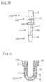
- a nucleus forming portion is formed on the outer periphery of a solid electrolyte 2 in a range up to a portion A at a trunk portion 202 from the tip of a tip portion 201, and then a plating film is formed on the nucleus forming portion.
- the insulating layer 17 made of MgAl 2 O 4 spinel or Al 2 O 3 is formed on the plating film at portions other than the tip portion 201 working as the external electrode 11.
- electrode leads 110 and electrode terminals 111 are formed on the insulating layer 17 so as to be electrically connected to the plating film at the tip portion 201 (see Fig. 21).
- the other structure is the same as the foregoing first embodiment.
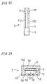
- the fourth embodiment relates to a stacked oxygen sensor element 5.
- the stacked oxygen sensor element 5 includes a plate solid electrolyte 2 provided with an external electrode 11 and an internal electrode 12.
- the external electrode 11 and the internal electrode 12 are obtained in the same manner as in the foregoing first embodiment, that is, by forming nucleus forming portions on electrode forming portions of the plate solid electrolyte 2, then forming plating films on the nucleus forming portions and burning the plating films.
- first and second protective layers 191 and 192 are formed in the order named.
- a heater board 59 having an atmosphere introducing duct and heaters 58 is arranged on the inner side of the solid electrolyte 2 where the internal electrode 12 is formed.
- the heater board 59 is a ceramic sheet of Al 2 O 3 formed by press forming, injection molding, sheet forming, lamination or the like.
- the external electrode 11 is electrically connected via an electrode lead 110 to an electrode terminal 111 exposed to the exterior.
- the internal electrode 12 is electrically connected via an electrode lead 120 to an electrode terminal 121 exposed to the exterior.
- the electrode terminals 111 and 121 are formed on an outer surface of the oxygen sensor element 5.
- the other structure is the same as the foregoing first embodiment.
- the present invention is also applicable to the stacked oxygen sensor element 5.
- the stacked oxygen sensor element 5 in this embodiment achieves effects similar to those of the foregoing first embodiment.
- the present invention is further applicable to, for example, a two-cell type stacked oxygen sensor element where electrodes are provided relative to a plurality of solid electrolytes.
Abstract
Description
- The present invention relates to an oxygen sensor element which can be used in an air-fuel ratio control for an automobile engine, and further relates to a method of producing such an oxygen sensor element.
- In the exhaust system of an automobile engine, an oxygen sensor is provided for measuring the oxygen concentration in the exhaust gas so as to perform an air-fuel ratio control based on measured values of the oxygen concentration.
- The oxygen sensor includes an oxygen sensor element for detecting the oxygen concentration. The oxygen sensor element includes a solid electrolyte and electrodes provided on the solid electrolyte. The electrodes include an internal electrode exposed to a reference gas and an external electrode exposed to a gas to be measured.
- For providing the foregoing electrodes at electrode forming portions of the solid electrolyte, the following method has been used:
- First, noble metal nuclei are adhered to the electrode forming portions of the solid electrolyte to form nucleus forming portions. Then, metal plating is applied to the nucleus forming portions to form plating films. Thereafter, the plating films are burned to form the foregoing electrodes on the solid electrolyte.
- The foregoing nucleus forming portions are achieved by spraying particles of noble metal, such as platinum (Pt), onto the electrode forming portions of the solid electrolyte.
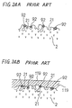
- As shown in Figs. 24A and 24B, a large number of fine holes or cavities are formed on the surface of the solid electrolyte. Accordingly, when the noble metal particles are applied onto the surface of the solid electrolyte at the electrode forming portions thereof, the noble metal particles enter the cavities of the solid electrolyte to form the nucleus forming portions. Thus, upon plating the nucleus forming portions, a plating liquid reacts with the noble metal particles within the cavities so that the plating films are organically tangled with particles of the solid electrolyte to achieve a strong adhesion force therebetween based on an anchor effect. Then, by burning the plating films, the electrodes are achieved which are hard to peel off from the surface of the solid electrolyte.
- However, there is the following problem in the foregoing method of forming the nucleus forming portions:
- Specifically, there may he formed a complicated pattern, as the foregoing electrode, on the surface of the solid electrolyte as shown, for example, in Fig. 2A and Fig. 9. Accordingly, in the foregoing forming method employing spraying of the noble metal particles, it is necessary to partially mask the surface of the solid electrolyte and thus it is difficult to produce the electrode of a complicated shape.
- Japanese First (unexamined) Patent Publication No. 4-95766 discloses another forming method, wherein a solution containing a noble metal compound is applied to the electrode forming portions of the solid electrolyte to form coating films and then, by heating the coating films at a high temperature, those components (for example, a binder) other than the noble metal in the solution are volatilized or decomposed so that only the noble metal nuclei are deposited to form nucleus forming portions.
- In the latter forming method, the nucleus forming portion can be easily provided at the electrode forming portion of a desired shape using, for example, screen printing, stamp printing, pad printing, roll transfer, dip method, spray method or dispenser method.
- However, the latter forming method has the following problem:
- Specifically, since the heating of the coating films is carried out at a high temperature, i.e. about 700°C or higher, flocculation of the noble metal advances so that the mean particle diameter of the noble metal nuclei becomes 0.1µm to 0.8µm. Hence, as shown in Fig. 24A, the
noble metal nuclei 92 can not enter thefine cavities 21 formed on the surface of thesolid electrolyte 2, but stay at entrances of thefine cavities 21. - In this case, as shown in Fig. 24B, the
plating film 119 can not advance into thefine cavities 21 so that the adhesion force based on the anchor effect can not be achieved between theplating film 119 and thesolid electrolyte 2. - Further, as shown in Fig. 24A, in the latter forming method, the
noble metal nuclei 92 are localized on the surface of thesolid electrolyte 2. This means that distances between the adjacentnoble metal nuclei 92 become large. As appreciated, the adhesion force between theplating film 119 and thesolid electrolyte 2 can not be achieved at portions where nonoble metal nuclei 92 exist, and thus, in the latter forming method, those portions where the adhesion force can not be achieved exist largely on the surface of thesolid electrolyte 2. - Consequently, in the latter forming method, such an oxygen sensor element tends to be produced, wherein the peeling-off of the electrode is liable to occur and the surface resistance at an interface between the electrode and the
solid electrolyte 2 is excessively large to disable outputs required for detection of the oxygen concentration. - Therefore, it is an object of the present invention to provide an oxygen sensor element, wherein an electrode is hard to peel off from a solid electrolyte and the surface resistance at an interface between the electrode and the solid electrolyte is small.
- It is another object of the present invention to provide a method of producing such an oxygen sensor element.
- According to one aspect of the present invention, an oxygen sensor element comprises a solid electrolyte having cavities on a surface thereof; and an electrode formed on the surface of the solid electrolyte, the electrode deeply entering the cavities for ensuring adhesion of the electrode relative to the surface of the solid electrolyte.
- It may be arranged that the electrode is in the form of a plating film produced via noble metal nuclei provided on the surface of the solid electrolyte, the noble metal nuclei having a mean particle diameter which is small enough for the noble metal nuclei to deeply enter the cavities.
- It may be arranged that the mean particle diameter of the noble metal nuclei is 0.05µm or smaller.
- It may be arranged that each of the cavities has finer cavities therein, and that the electrode further enters the finer cavities.
- According to another aspect of the present invention, a method of producing an oxygen sensor element which includes a solid electrolyte having cavities on a surface thereof and an electrode formed on the surface of the solid electrolyte, comprises the steps of: applying a solution containing a noble metal compound for nucleus formation to the surface at an electrode forming portion of the solid electrolyte to form a coating film; heat-treating the coating film by heating to form a nucleus forming portion where noble metal nuclei are deposited; plating the nucleus forming portion to form a plating film, the plating film deeply entering the cavities; and burning the plating film to form the electrode so that the electrode deeply enters the cavities.
- It may be arranged that the noble metal nuclei have a mean particle diameter which is small enough for the noble metal nuclei to deeply enter the cavities.
- It may be arranged that the mean particle diameter of the noble metal nuclei is 0.05µm or smaller.
- It may be arranged that the coating film is heat-treated at a temperature in the range of 200°C to 600°C.
- It may be arranged that the noble metal compound is an organic noble metal compound.
- It may be arranged that a concavo-convex treatment is applied to the surface of the solid electrolyte for promoting irregularities to be formed on the surface.
- It may be arranged that a concentration of the noble metal compound relative to the solution is 0.05% by weight to 0.4% by weight.
- It may be arranged that noble metal in the noble metal compound is at least one selected from the group consisting of Pt, Pd, Au and Rh.
- The present invention will be understood more fully from the detailed description given hereinbelow, taken in conjunction with the accompanying drawings.
- In the drawings:
- Fig. 1A is an enlarged view of the surface of a solid electrolyte of an oxygen sensor element according to a first embodiment of the present invention;
- Fig. 1B is an enlarged view of a plating film formed on the surface of the solid electrolyte shown in Fig. 1A;
- Fig. 1C is an enlarged view of a fine hole or cavity formed on the surface of the solid electrolyte shown in Fig. 1B;
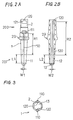
- Fig. 2A is a front view of the oxygen sensor element according to the first embodiment of the present invention;
- Fig. 2B is a longitudinal-sectional view of the oxygen sensor element shown in Fig. 2A;
- Fig. 3 is a cross-sectional view of the oxygen sensor element at its tip portion shown in Figs. 2A and 2B;
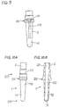
- Fig. 4A is a front view of a nozzle to be used upon forming an electrode according to the first embodiment of the present invention;
- Fig. 4B is a side view of the nozzle shown in Fig. 4A;
- Fig. 5A is a front view showing a modification of the nozzle shown in Figs. 4A and 4B:
- Fig. 5B is a side view of the nozzle shown in Fig. 5A;
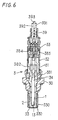
- Fig. 6 is a longitudinal-sectional view of an oxygen sensor according to the first embodiment of the present invention;
- Fig. 7A is a front view showing a modification of the oxygen sensor element according to the first embodiment of the present invention;
- Fig. 7B is a longitudinal-sectional view of the oxygen sensor element shown in Fig. 7A;
- Fig. 8 is a cross-sectional view of the oxygen sensor element at its tip portion shown in Figs. 7A and 7B;
- Fig. 9 is a front view showing a modification of the oxygen sensor element according to the first embodiment of the present invention;
- Fig. 10A is a front view showing a modification of the oxygen sensor element according to the first embodiment of the present invention;
- Fig. 10B is a longitudinal-sectional view of the oxygen sensor element shown in Fig. 10A;
- Fig. 11A is a front view showing a modification of the oxygen sensor element according to the first embodiment of the present invention;
- Fig. 11B is a longitudinal-sectional view of the oxygen sensor element shown in Fig. 11A:
- Fig. 12A is a front view showing a modification of the oxygen sensor element according to the first embodiment of the present invention;
- Fig. 12B is a longitudinal-sectional view of the oxygen sensor element shown in Fig. 12A;
- Fig. 13 is an enlarged view of an external electrode of the oxygen sensor element shown in Figs. 12A and 12B;
- Fig. 14A is a front view showing a modification of the oxygen sensor element according to the first embodiment of the present invention;
- Fig. 14B is a longitudinal-sectional view of the oxygen sensor element shown in Fig. 14A;
- Fig. 15A is a front view showing a modification of the oxygen sensor element according to the first embodiment of the present invention;
- Fig. 15B is a longitudinal-sectional view of the oxygen sensor element shown in Fig. 15A;
- Fig. 16 is a cross-sectional view of the oxygen sensor element at its tip portion shown in Figs. 15A and 15B;
- Fig. 17 is a longitudinal-sectional view of an oxygen sensor element at its tip portion according to a second embodiment of the present invention;
- Fig. 18 is a longitudinal-sectional view showing a modification of the oxygen sensor element according to the second embodiment of the present invention;
- Fig. 19 is a sectional view showing interfaces between a solid electrolyte and an electrode and between the electrode and a protective layer according to a modification of the second embodiment of the present invention;
- Fig. 20 is a front view of an oxygen sensor element according to a third embodiment of the present invention;
- Fig. 21 is a longitudinal-sectional view of the oxygen sensor element at its tip portion shown in Fig. 20;
- Fig. 22 is a front view of a stacked oxygen sensor element according to a fourth embodiment of the present invention;
- Fig. 23 is a cross-sectional view of the oxygen sensor element shown in Fig. 22;
- Fig. 24A is an enlarged view of the surface of a solid electrolyte of a conventional oxygen sensor element; and
- Fig. 24B is an enlarged view of a plating film formed on the surface of the solid electrolyte shown in Fig. 24A.
- Now, preferred embodiments of the present invention will be described hereinbelow with reference to the accompanying drawings. Throughout the figures, the same reference signs represent the same or corresponding elements.
- The first embodiment of the present invention will be described hereinbelow with reference to Figs. 1A to 6.
- As shown in Figs. 2A and 2B, an
oxygen sensor element 1 includes a cylindricalsolid electrolyte 2 and electrodes formed on the surface of thesolid electrolyte 2. The electrodes include anexternal electrode 11 formed on an outer periphery of thesolid electrolyte 2 and aninternal electrode 12 formed on an inner periphery of thesolid electrolyte 2. - For producing the
oxygen sensor element 1, a solution containing a noble metal compound for nucleus formation is applied to electrode forming portions of thesolid electrolyte 2 to form coating films. - Then, the coating films are subjected to heat treatment by heating so as to form
nucleus forming portions 20 whereinnoble metal nuclei 22 are deposited as shown in Fig. 1A (showing only one of the nucleus forming portions 20). Thenoble metal nuclei 22 are in the form of noble metal spheres or hemispheres obtained by decomposing the noble metal compound contained in the solution through the heat treatment of the coating films so as to deposit on the surface of thesolid electrolyte 2. - Then, metal plating is applied to the
nucleus forming portions 20 to form platingfilms 119 thereon. Thereafter, the platingfilms 119 are burned to achieve the foregoingelectrodes - The mean particle diameter of the
noble metal nuclei 22 at thenucleus forming portions 20 is 0.05µm or smaller. - Now, the
oxygen sensor element 1 will be described in detail. - As shown in Figs. 2A to 3, the
solid electrolyte 2 is closed at its tip to provide areference gas chamber 13. Thesolid electrolyte 2 is made of zirconia. As described above, theexternal electrode 11 is disposed on the outer periphery of thesolid electrolyte 2 while theinternal electrode 12 is disposed on the inner periphery thereof defining thereference gas chamber 13. - On the outer periphery of the
solid electrolyte 2 is provided acollar portion 29 protruding radially outward. At the upper side of thecollar portion 29, two steps are formed to provide three diameter-different portions. - As shown in Fig. 2A, the
external electrode 11 is formed in a strip shape at atip portion 201 of thesolid electrolyte 2. As shown in Fig. 2B, theinternal electrode 12 is formed on the inner periphery at a portion defining thereference gas chamber 13 and corresponding to theexternal electrode 11. Theexternal electrode 11 is electrically connected to electrodeterminals 111 via electrode leads 110 each extending upward from theexternal electrode 11. Similarly, theinternal electrode 12 is electrically connected to electrodeterminals 121 via electrode leads 120 each extending upward from theinternal electrode 12. Theelectrode terminals solid electrolyte 2 at atrunk portion 202 thereof. - As shown in Fig. 7B, the
electrode terminals 121 may be formed on the inner periphery of thesolid electrolyte 2. - The
external electrode 11, the electrode leads 110 and theelectrode terminals 111 are formed integral with each other. Similarly, theinternal electrode 12, the electrode leads 120 and theelectrode terminals 121 are formed integral with each other. - As shown in Fig. 3, the electrode leads 110 are provided in pair and the electrode leads 120 are also provided in pair. The electrode leads 110 and 120 are arranged in pairs in the same radial directions of the
solid electrolyte 2 with a phase difference of 180°. - On the other hand, as shown in Fig. 8, the electrode leads 110 and 120 may be arranged in four different radial directions with phase differences of 90°. Further, the number of the electrode leads 110 or 120 may take a value other than two as long as the sensor output can be taken out.
- A length L1 of the
external electrode 11 and a length L2 of theinternal electrode 12 are set equal to each other, each being set to 10mm. A thickness of each of theelectrodes electrode lead 110 is set to 23mm, and a length R2 of theelectrode lead 120 is set to 34mm. Further, each of theelectrode terminals electrode terminal - It is preferable that the length L1, L2 is set to 2mm to 20mm. If the length L1, L2 is smaller than 2mm, it is possible that the required sensor output can not be achieved. On the other hand, if the length L1, L2 is greater than 20mm, it is possible that the sensor output includes an output from a portion (low temperature portion) whose response characteristic is poor so that the whole response characteristic is deteriorated. Further, the cost performance may be possibly lowered.
- Now, an oxygen sensor 3 incorporating the foregoing
oxygen sensor element 1 will be described. - As shown in Fig. 6, the oxygen sensor 3 includes a
housing 30 and theoxygen sensor element 1 received through thehousing 30. At the lower side of thehousing 30 is formed a to-be-measured gas chamber 33 defined by a to-be-measuredgas side cover 330 which is double-structured for protecting thetip portion 201 of theoxygen sensor element 1. At the upper side of thehousing 30 are provided three-stage atmosphere side covers 31, 32 and 33. - A rod-shaped
heater 34 is received in thereference gas chamber 13 of theoxygen sensor element 1 with given clearances relative to the inner periphery of thesolid electrolyte 2 defining thereference gas chamber 13. - An elastic insulating
member 39 with leads 391-393 passing therethrough is fitted into the atmosphere side cover 32 at its upper end. The leads 391 and 392 are for taking out a current generated through thesolid electrolyte 2 as a signal and sending it out to the exterior. On the other hand, thelead 393 is for energizing theheater 34 to generate heat. - At the lower ends of the
leads terminals terminals oxygen sensor element 1. Theterminals electrode terminals oxygen sensor element 1. - Now, a method of producing the foregoing
oxygen sensor element 1 will be described in detail. - As described before, the
external electrode 11, the electrode leads 110 and theelectrode terminals 111 are formed integral with each other, and theinternal electrode 12, the electrode leads 120 and theelectrode terminals 121 are formed integral with each other. Accordingly, each of the electrode forming portions of thesolid electrolyte 2 includes not only a portion where theelectrode electrode terminals - First, zirconia is formed into a shape as shown in Figs. 2A and 2B and then provisionally burned to obtain the
solid electrolyte 2 in the form of a zirconia sintered body (ZrO2-Y2O3). Thesolid electrolyte 2 may be made of other materials as long as ionic conductivity is achieved. Subsequently, a solution containing a noble metal compound is applied to the electrode forming portions on the inner and outer peripheries of thesolid electrolyte 2 to form coating films (see Figs. 2A and 2B). - As the noble metal compound, an organic platinum compound, such as dibenzylidene platinum (C16H16Pt), is used. In the foregoing solution, the organic platinum compound is contained at 0.4% by weight. Other than the organic platinum compound, the solution contains an acrylic binder and terpineol.
- The dispenser method is used for applying the foregoing solution to the electrode forming portion on the inner periphery. On the other hand, the pad printing is carried out several times for applying the foregoing solution to the electrode forming portion on the outer periphery.
- In the dispenser method, a
nozzle 4 having an inside passage and as shown in Figs. 4A and 4B is used. Atip portion 41 of thenozzle 4 is bent by an angle of about 90° and formed at its center with aninjection hole 410 for injecting the solution. - First, the
nozzle 4 is inserted into thesolid electrolyte 2 near the bottom of thereference gas chamber 13. Upon insertion of thenozzle 4, the solution is applied to the electrode forming portion for one of the electrode leads 120. Then, at that position, the solution is further applied while moving thetip portion 41 of thenozzle 4 vertically and circumferentially relative to the inner periphery of the solid electrolyte, so as to complete application of the solution for theinternal electrode 12. - Then, while injecting the solution from the
tip portion 41, thenozzle 4 is moved upward of thereference gas chamber 13. At this time, thetip portion 41 of thenozzle 4 is not moved circumferentially relative to the inner periphery of thesolid electrolyte 2. - Through the foregoing operation, the application of the solution to the electrode forming portion for the
internal electrode 12 and the pair of electrode leads 120 (see Fig. 3) is completed. - Thereafter, the solution is applied to the electrode forming portion for lead portions 129 (see Fig. 2A) drawing out the corresponding electrode leads 120 to the outer periphery of the
solid electrolyte 2 and for theelectrode terminals 121 on the outer periphery of thesolid electrolyte 2 near its upper end, and then the application of the solution is completed. - Instead of the
nozzle 4 shown in Figs. 4A and 4B, anozzle 4 shown in Figs. 5A and 5B may be used. A tip portion of thenozzle 4 in Figs. 5A and 5B includes aporous member 42. Through pores of theporous member 42, the solution is injected and applied to the electrode forming portion. - Subsequently, the coating films at the electrode forming portions are dried.
- Then, the coating films are subjected to heat treatment at 400°C for decomposing the organic platinum compound contained in the coating films so as to deposit the noble metal nuclei, i.e. the platinum nuclei at the foregoing electrode forming portions, while removing the other components, such as the binder, through volatilization or decomposition.
- Through the foregoing operation, as shown in Figs. 1A to 1C, the
nucleus forming portions 20 are formed wherein thenoble metal nuclei 22 are uniformly dispersed and further deeply enter fine holes orcavities 21 which are formed in large number on the surface of thesolid electrolyte 2. - Then, as shown in Fig. 1B, electroless plating of platinum is applied to the
nucleus forming portions 20 to form the platingfilms 119. Theplating film 119 may be made of noble metal, other than platinum, such as palladium (Pd), gold (Au) and rhodium (Rh). It is not necessary that the plating film is made of the same material as the noble metal nucleus. Upon plating, thenoble metal nuclei 22 react with the noble metal contained in a plating liquid so as to facilitate formation of the platingfilms 119. Since thenoble metal nuclei 22 deeply enter thefine cavities 21, the plating liquid and thus the platingfilms 119 also deeply enter thefine cavities 21. Thereafter, the platingfilms 119 together with thesolid electrolyte 2 are burned at 1,000°C to achieve the external andinternal electrodes electrode terminals - Through the foregoing operation, the
oxygen sensor element 1 according to the first embodiment is obtained. - The
oxygen sensor element 1 has the following advantages: - As described above, a large number of the
fine cavities 21 are formed on the surface of thesolid electrolyte 2 as shown in Fig. 1A. On the other hand, as described before, the mean particle diameter of thenoble metal nuclei 22 produced through the foregoing operation is no greater than 0.05µm which is much smaller as compared with thefine cavities 21. Accordingly, thenoble metal nuclei 22 can deeply enter thefine cavities 21. Further, as best shown in Fig. 1C, thenoble metal nuclei 22 can even enter finer holes orcavities 210 formed within thefine cavities 21. - Further, a distance d between the adjacent
noble metal nuclei 22 is very small. This means that thenoble metal nuclei 22 are not localized but dispersed uniformly over the electrode forming portions to form thenucleus forming portions 20. - For this reason, each of the plating
films 119 formed on thenucleus forming portions 20 can be securely adhered to thesolid electrolyte 2 based on a strong anchor effect achieved at an interface between theplating film 119 and thesolid electrolyte 2. Accordingly, a strong adhesion force can be achieved between thesolid electrolyte 2 and each of the external andinternal electrodes films 119. Hence, the external andinternal electrodes solid electrolyte 2. - Further, since the
noble metal nuclei 22 are dispersed uniformly all over thenucleus forming portions 20, the foregoing strong adhesion force is exerted all over the interface between thesolid electrolyte 2 and each of the external andinternal electrodes electrode terminals - In the foregoing first embodiment, the dispenser method and the pad printing are used for applying the solution to the electrode forming portions. On the other hand, it may be arranged to use at least one of the screen printing, the stamp printing, the roll transfer, the dip method and the spray method for applying the solution to the electrode forming portions.
- It is preferable to use the pad printing or the roll transfer since a coating film of a desired shape can be easily formed on a curved surface, such as the inner/outer periphery of the cylindrical solid electrolyte, and further a coating film can be formed with accuracy.
- In the foregoing first embodiment, the heat treatment to the coating films is performed at 400°C. It is preferable that the heat treatment to the coating films is performed at a temperature in the range of 200°C to 600°C.
- When the heat treatment temperature is higher than 600°C. flocculation of the noble metal is liable to occur so that the mean particle diameter of the noble metal nuclei may become greater than 0.05µm. Following the flocculation of the noble metal, the noble metal nuclei may be localized. Accordingly, it is possible that the electrode is liable to peel off from the solid electrolyte.
- On the other hand, when the heat treatment temperature is lower than 200°C, it is possible that decomposition of the noble metal compound does not practically occur. Accordingly, deposition of the noble metal nuclei does not advance to disable formation of the nucleus forming portion. Thus, the plating film does not practically adhere to the solid electrolyte so that the solid electrolyte may be partially exposed to the exterior. Further, it is possible that those components, other than the noble metal compound, contained in the solution or carbon produced by those components remain on the surface of the solid electrolyte. In this case, the strong adhesion force between the noble metal nuclei and the solid electrolyte may not be achieved.
- In the foregoing first embodiment, the noble metal in the noble metal compound for nucleus formation is platinum. It is preferable that noble metal in a noble metal compound for nucleus formation is at least one selected from the group consisting of Pt, Pd, Au and Rh. These metals have a catalytic function for facilitating plating so that excellent plating is achieved on the solid electrolyte. Further, it is preferable to use an organic noble metal compound as the noble metal compound as in the foregoing first embodiment. The organic noble metal compound makes it easy to adjust viscosity of the solution, thereby making it easy to apply the solution to the electrode forming portion of the solid electrolyte.
- In the foregoing first embodiment, the organic platinum compound is contained in the solution at 0.4% by weight. It is preferable that the concentration of the noble metal compound relative to the solution is in the range of 0.05% by weight to 0.4% by weight.
- When the concentration is smaller than 0.05% by weight, the amount of the noble metal compound is so small that it may be difficult to form an nucleus forming portion where the noble metal nuclei are uniformly dispersed. In this case, since the strong adhesion force can not be achieved between the plating film and the solid electrolyte, the electrode may be liable to peel off from the solid electrode.
- On the other hand, when the concentration exceeds 0.4% by weight, flocculation of the noble metal may be liable to occur to increase the mean particle diameter of the noble metal nuclei to be greater than 0.05µm. Following the flocculation of the noble metal, the noble metal nuclei may be localized. Accordingly, it is possible that the electrode is liable to peel off from the solid electrolyte.
- Now, the performance evaluation of samples (oxygen sensor elements) produced according to the present invention (hereinafter also referred to as "inventive samples") and comparative samples (oxygen sensor elements) will be described hereinbelow.
- Table 1 relates to inventive samples 1-19 while Table 2 relates to comparative samples 20-28. In samples 1-28, organic noble metal compounds were used as noble metal compounds. When noble metal was Pt, dibenzylidene platinum (C16H16Pt) was used as an organic noble metal compound and, when noble metal was Pd, balsam palladium (C10H18SPdClx, where x=1-3) was used as an organic noble metal compound.
- The evaluation of samples 1-28 was carried out based on a resistance value test and a peeling test.
- A resistance value of each sample was obtained by measuring a dc resistance between the external and internal electrodes at 400°C.
- The peeling test was carried out by adhering an adhesive tape to the external electrode and then peeling off the tape. After peeling off the tape, macro-observation and micro-observation of the external electrode were performed. If no peeling of the external electrode was observed both in macro-observation and micro-observation, O was indicated in Table 1 and Table 2.
- The macro-observation was performed using a magnifying glass, while the micro-observation was performed using a scanning electron microscope.
- Now, the results of the performance evaluation of samples 1-28 will be given hereinbelow.
- By comparison between Table 1 and Table 2, it is seen that inventive samples 1-19 all showed low resistance values, meaning that the surface resistances thereof were small. Thus, each inventive sample can ensure an output necessary for detection of the oxygen concentration. As seen from Table 1, the results of the peeling test were also excellent in all inventive samples 1-19.
- On the other hand, comparative samples 20-28 showed large resistance values, and the results of the peeling test were also poor.
- Accordingly, it has been confirmed that, in each of the oxygen sensor elements of the inventive samples, the electrode was hard to peel off from the solid electrolyte, the surface resistance at an interface between the electrode and the solid electrolyte was small, and the output necessary for detection of the oxygen concentration was ensured.
- As shown in Table 3, an inorganic noble metal compound can also be used as a noble metal compound. In each of
inventive samples inventive samples Table 1 SAMPLE NO. NOBLE METAL NOBLE METAL NUCLEUS MEAN PARTICLE DIAMETER (µm) NOBLE METAL CONCENTRATION (% by weight) HEAT TREATMENT TEMP. (°C) RESISTANCE VALUE (KΩ) PEELING TEST 1 Pt 0.01 0.4 400 9 O 2 Pt 0.007 0.1 200 10 O 3 Pt 0.01 0.05 600 9 O 4 Pt 0.005 0.05 200 10 O 5 Pt 0.04 0.4 400 11 O 6 Pt 0.03 0.1 600 9 O 7 Pt 0.006 0.1 200 11 O 8 Pt 0.008 0.05 400 10 O 9 Pt 0.08 0.4 600 11 O 10 Pd 0.008 0.4 200 11 O 11 Pd 0.01 0.1 400 10 O 12 Pd 0.01 0.05 600 10 O 13 Pd 0.005 0.05 200 9 O 14 Pd 0.03 0.4 400 10 O 15 Pd 0.05 0.1 600 9 O 16 Pd 0.007 0.1 200 10 O 17 Pd 0.01 0.06 400 10 O 18 Pd 0.09 0.4 600 12 O 19 Rh 0.01 0.4 400 10 O Table 2 SAMPLE NO. NOBLE METAL NOBLE METAL NUCLEUS MEAN PARTICLE DIAMETER (µM) NOBLE METAL CONCENTRATION (% by weight) HEAT TREATMENT TEMP. (°C) RESISTANCE VALUE (kΩ) PEELING TEST 20 Pt *1 0.4 100 *2 X 21 Pt 0.11 0.4 700 32 X 22 Pd 0.15 0.4 900 *2 X 23 Pd *1 0.4 100 *2 X 24 Pd 0.12 0.4 700 96 X 25 Pt 0.18 0.4 900 *2 X 26 Pt 0.001 0.01 600 *2 X 27 Pt 0.12 0.6 600 30 X 28 Rh 0.15 0.4 900 *2 X *1 unmeasurable due to residual binder
*2 resistance value ∞ due to excessive electrode peeling-offTable 3 SAMPLE NO. NOBLE METAL COMPOUND NOBLE METAL NUCLEUS MEAN PARTICLE DIAMETER (µM) RESISTANCE VALUE (kΩ) PEELING TEST 29 H2PtCl6 0.005 9 O 30 Pt PARTICLES 0.05 12 O - In the foregoing first embodiment, the
solid electrolyte 2 of theoxygen sensor element 1 is formed with two steps at the upper side of thecollar portion 29 as shown in Figs. 2A and 2B. On the other hand, as shown in Fig. 9, asolid electrolyte 2 having only one step at the upper side of acollar portion 29 may also be used. Further, a solid electrolyte having no step may also be used. - Figs. 10A and 10B show a modification of the oxygen sensor element according to the foregoing first embodiment, wherein a configuration of each of electrode forming portions on a
solid electrolyte 2 differs from that of the foregoing first embodiment. - Specifically, as seen from Fig. 10A, a plating film is formed on the outer periphery of the
solid electrolyte 2 over a wide range including atip portion 201 and atrunk portion 202 so as to form a cup-shapedexternal electrode 11, acylindrical electrode lead 110 and acylindrical electrode terminal 111. On the other hand, as seen from Fig. 10B, a plating film is formed all over the inner periphery of thesolid electrolyte 2 so as to form a cup-shapedinternal electrode 12, acylindrical electrode lead 120 and acylindrical electrode terminal 121. - The other structure is the same as the foregoing first embodiment.
- Figs. 11A and 11B show a modification of the oxygen sensor element according to the foregoing first embodiment, wherein a configuration of each of electrode forming portions on a
solid electrolyte 2 slightly differs from that of the foregoing first embodiment. - Specifically, as seen from Fig. 11A, an
external electrode 11 covers the whole of atip portion 201 of thesolid electrolyte 2 on the outer periphery thereof as opposed to the foregoing first embodiment. Similarly, as seen from Fig. 11B, aninternal electrode 12 covers the whole of thetip portion 201 on the inner periphery thereof, and further,electrode terminals 121 are formed on the inner periphery of thesolid electrolyte 2. - The other structure is the same as the foregoing first embodiment.
- Figs. 12A, 12B and 13 show a modification of the oxygen sensor element according to the foregoing first embodiment, wherein a configuration of each of electrode forming portions on a
solid electrolyte 2 slightly differs from that of the foregoing first embodiment. - Specifically, as seen from Fig. 12A, an
external electrode 11 is formed into a mesh shape. Similarly, as seen from Fig. 12B, aninternal electrode 12 is also formed into a mesh shape, and further,electrode terminals 121 are formed on the inner periphery of thesolid electrolyte 2. - The other structure is the same as the foregoing first embodiment.
- Figs. 14A and 14B show a modification of the oxygen sensor element according to the foregoing first embodiment, wherein a configuration of each of electrode forming portions on a
solid electrolyte 2 slightly differs from that of the foregoing first embodiment. - Specifically, as seen from Figs. 14A and 14B, a length of each of an
external electrode 11 and aninternal electrode 12 is set approximately half the length L1, L2 of theelectrode electrode terminals 121 are formed on the inner periphery of thesolid electrolyte 2. - The other structure is the same as the foregoing first embodiment.
- Figs. 15A, 15B and 16 show a modification of the oxygen sensor element according to the foregoing first embodiment, wherein a configuration of each of electrode forming portions on a
solid electrolyte 2 differs from that of the foregoing first embodiment. - Specifically, in this modification, the number of electrode leads 110 extending from an
external electrode 11 is four, and similarly, the number of electrode leads 120 extending from aninternal electrode 12 is also four, and further,electrode terminals 121 are formed on the inner periphery of thesolid electrolyte 2. - The other structure is the same as the foregoing first embodiment.
- In the modification shown in Figs. 10A and 10B, since the shapes of the electrode forming portions are simple, formation of nucleus forming portions can be easily achieved to facilitate production of the oxygen sensor element.
- In the modification shown in Figs. 11A and 11B, since the electrode forming portions cover the whole of the
tip portion 201 on the inner and outer peripheries, the masking operation can be partly omitted upon formation of the nucleus forming portions so that production of the oxygen sensor element can be facilitated. - In the modification shown in Figs. 12A, 12B and 13, since the
external electrode 11 and theinternal electrode 12 are formed into the mesh shape diffusion of oxygen to thesolid electrolyte 2 is improved. Thus, theoxygen sensor element 1 is excellent in response characteristic. - The improvement in oxygen diffusion can be achieved when only one of the
external electrode 11 and theinternal electrode 12 is formed into the mesh shape. - In the modification shown in Figs. 14A and 14B, the amount of the noble metal to be used can be reduced.
- In the modification shown in Figs. 15A, 15B and 16, even if deterioration occurs to one pair of the electrode leads 110 or 120, the required sensor output can be achieved.
- Now, the second embodiment of the present invention will be described hereinbelow with reference to Fig. 17.
- As shown in Fig. 17, an
oxygen sensor element 1 includes anexternal electrode 11 and aninternal electrode 12 similar to those in the modification shown in Figs. 11A and 11B. Further, a firstprotective layer 191 is formed on theexternal electrode 11 so as to cover the whole of theexternal electrode 11. - The first
protective layer 191 also has a function of a diffusion resistance layer. The firstprotective layer 191 has a thickness of 100µm and a porosity of 20% and is formed of MgAl2O4 spinel through plasma spraying. - The other structure is the same as the foregoing first embodiment.
- In the second embodiment, since the first
protective layer 191 is provided on the surface of theexternal electrode 11, theoxygen sensor element 1 is excellent in durability of theexternal electrode 11. - Fig. 18 shows a modification of the oxygen sensor element according to the foregoing second embodiment. In the modification shown in Fig. 18, the
oxygen sensor element 1 further includes a secondprotective layer 192 formed on the firstprotective layer 191. The secondprotective layer 192 has a thickness of 120µm and a porosity of 20% to 50% and is made of Al2O3. - Specifically, the second
protective layer 192 can be formed by slurrying Al2O3, coating the surface of the firstprotective layer 191 with slurried Al2O3 using the dip method, and then applying heat treatment thereto. - The other structure is the same as the foregoing second embodiment.
- In the modification shown in Fig. 18, in addition to the foregoing effect of the second embodiment, a trap effect is achieved owing to the second
protective layer 192. Thus, theoxygen sensor element 1 is further excellent in durability of theexternal electrode 11. - As shown in Fig. 19, it is preferable that a concavo-convex treatment is applied to the surface of the
solid electrolyte 2 for promoting irregularities to be formed thereon. Since the irregularities are promoted on the surface of thesolid electrolyte 2 through the concavo-convex treatment, contact areas between thesolid electrolyte 2 and the plating film can be increased, more noble metal nuclei can be in abutment with the plating film, and the plating film can deeply engage with the irregularities on the surface of thesolid electrolyte 2. Thus, a strong adhesion force can be exerted between thesolid electrolyte 2 and the plating film and thus the electrode. As seen from Fig. 19, the irregularities on the surface of thesolid electrolyte 2 can increase not only an adhesive force between thesolid electrolyte 2 and theexternal electrode 11, but also an adhesive force between theexternal electrode 11 and the firstprotective layer 191. Thus, theoxygen sensor element 1 having excellent durability can be achieved. The foregoing concavo-convex treatment can be performed by etching, powder application, thermal spraying or the like. - Now, the third embodiment of the present invention will be described hereinbelow with reference to Figs. 20 and 21.
- As shown in Figs. 20 and 21, an
oxygen sensor element 1 includes an insulatinglayer 17. For producing theoxygen sensor element 1 having the insulatinglayer 17, a nucleus forming portion is formed on the outer periphery of asolid electrolyte 2 in a range up to a portion A at atrunk portion 202 from the tip of atip portion 201, and then a plating film is formed on the nucleus forming portion. - Thereafter, as shown in Fig. 20, the insulating
layer 17 made of MgAl2O4 spinel or Al2O3 is formed on the plating film at portions other than thetip portion 201 working as theexternal electrode 11. - Then, electrode leads 110 and
electrode terminals 111 are formed on the insulatinglayer 17 so as to be electrically connected to the plating film at the tip portion 201 (see Fig. 21). - Thereafter, by burning the
solid electrolyte 2, theoxygen sensor element 1 is obtained. - The other structure is the same as the foregoing first embodiment.
- In the
oxygen sensor element 1 according to the third embodiment, since the portions whose response characteristics are poor are masked by the insulatinglayer 17, sensor outputs from those portions are not included in the sensor output so that an excellent response characteristic can be achieved on the whole. - Now, the fourth embodiment of the present invention will be described hereinbelow with reference to Figs. 22 and 23.
- As shown in Figs. 22 and 23, the fourth embodiment relates to a stacked
oxygen sensor element 5. The stackedoxygen sensor element 5 includes a platesolid electrolyte 2 provided with anexternal electrode 11 and aninternal electrode 12. - The
external electrode 11 and theinternal electrode 12 are obtained in the same manner as in the foregoing first embodiment, that is, by forming nucleus forming portions on electrode forming portions of the platesolid electrolyte 2, then forming plating films on the nucleus forming portions and burning the plating films. - On the outer side of the
solid electrolyte 2 where theexternal electrode 11 is formed, first and secondprotective layers - On the inner side of the
solid electrolyte 2 where theinternal electrode 12 is formed, aheater board 59 having an atmosphere introducing duct andheaters 58 is arranged. - The
heater board 59 is a ceramic sheet of Al2O3 formed by press forming, injection molding, sheet forming, lamination or the like. - The
external electrode 11 is electrically connected via anelectrode lead 110 to anelectrode terminal 111 exposed to the exterior. Similarly, theinternal electrode 12 is electrically connected via anelectrode lead 120 to anelectrode terminal 121 exposed to the exterior. Theelectrode terminals oxygen sensor element 5. - The other structure is the same as the foregoing first embodiment.
- As appreciated, the present invention is also applicable to the stacked
oxygen sensor element 5. The stackedoxygen sensor element 5 in this embodiment achieves effects similar to those of the foregoing first embodiment. The present invention is further applicable to, for example, a two-cell type stacked oxygen sensor element where electrodes are provided relative to a plurality of solid electrolytes. - While the present invention has been described in terms of the preferred embodiments, the invention is not to be limited thereto, but can be embodied in various ways without departing from the principle of the invention as defined in the appended claims.
Claims (12)
- An oxygen sensor element comprising:a solid electrolyte having cavities on a surface thereof; andan electrode formed on the surface of said solid electrolyte, said electrode deeply entering said cavities for ensuring adhesion of said electrode relative to the surface of said solid electrolyte.
- The oxygen sensor element according to claim 1, wherein said electrode is in the form of a plating film produced via noble metal nuclei provided on the surface of said solid electrolyte, said noble metal nuclei having a mean particle diameter which is small enough for the noble metal nuclei to deeply enter said cavities.
- The oxygen sensor element according to claim 2, wherein the mean particle diameter of said noble metal nuclei is 0.05µm or smaller.
- The oxygen sensor element according to claim 1, wherein each of said cavities has finer cavities therein, and wherein said electrode further enters said finer cavities.
- A method of producing an oxygen sensor element which includes a solid electrolyte having cavities on a surface thereof and an electrode formed on the surface of said solid electrolyte, said method comprising the steps of:applying a solution containing a noble metal compound for nucleus formation to said surface at an electrode forming portion of said solid electrolyte to form a coating film;heat-treating said coating film by heating to form a nucleus forming portion where noble metal nuclei are deposited;plating said nucleus forming portion to form a plating film, said plating film deeply entering said cavities; andburning said plating film to form said electrode so that said electrode deeply enters said cavities.
- The method according to claim 5, wherein said noble metal nuclei have a mean particle diameter which is small enough for the noble metal nuclei to deeply enter said cavities.
- The method according to claim 6, wherein the mean particle diameter of said noble metal nuclei is 0.05µm or smaller.
- The method according to claim 5, wherein said coating film is heat-treated at a temperature in the range of 200°C to 600°C.
- The method according to claim 5, wherein said noble metal compound is an organic noble metal compound.
- The method according to claim 5, wherein a concavo-convex treatment is applied to the surface of said solid electrolyte for promoting irregularities to be formed on said surface.
- The method according to claim 5, wherein a concentration of said noble metal compound relative to said solution is 0.05% by weight to 0.4% by weight.
- The method according to claim 5, wherein noble metal in said noble metal compound is at least one selected from the group consisting of Pt, Pd, Au and Rh.
Applications Claiming Priority (3)
| Application Number | Priority Date | Filing Date | Title |
|---|---|---|---|
| JP150255/96 | 1996-05-21 | ||
| JP15025596A JP3811991B2 (en) | 1996-05-21 | 1996-05-21 | Oxygen sensor element manufacturing method and oxygen sensor element |
| JP15025596 | 1996-05-21 |
Publications (3)
| Publication Number | Publication Date |
|---|---|
| EP0809101A2 true EP0809101A2 (en) | 1997-11-26 |
| EP0809101A3 EP0809101A3 (en) | 1999-11-10 |
| EP0809101B1 EP0809101B1 (en) | 2004-02-04 |
Family
ID=15492953
Family Applications (1)
| Application Number | Title | Priority Date | Filing Date |
|---|---|---|---|
| EP97108239A Expired - Lifetime EP0809101B1 (en) | 1996-05-21 | 1997-05-21 | Oxygen sensor element and method of producing same |
Country Status (6)
| Country | Link |
|---|---|
| US (2) | US5948225A (en) |
| EP (1) | EP0809101B1 (en) |
| JP (1) | JP3811991B2 (en) |
| KR (1) | KR100230601B1 (en) |
| CN (1) | CN1122841C (en) |
| DE (1) | DE69727420T2 (en) |
Cited By (3)
| Publication number | Priority date | Publication date | Assignee | Title |
|---|---|---|---|---|
| EP0896219A1 (en) * | 1997-08-07 | 1999-02-10 | Denso Corporation | Improved structure of oxygen sensing element |
| EP0924515A2 (en) * | 1997-11-20 | 1999-06-23 | Denso Corporation | Solid electrolyte with inner reference chamber and electrodes on inner and outer surfaces |
| EP1023590A1 (en) * | 1997-10-16 | 2000-08-02 | Global Systems Incorporated | Chemical plating method, electrolytic cell and automotive oxygen sensor using it |
Families Citing this family (31)
| Publication number | Priority date | Publication date | Assignee | Title |
|---|---|---|---|---|
| JP3532366B2 (en) * | 1996-11-18 | 2004-05-31 | 日本特殊陶業株式会社 | Heat-resistant metal sheath lead wire for sensor |
| JP3605984B2 (en) * | 1997-01-23 | 2004-12-22 | 株式会社デンソー | Method and apparatus for manufacturing oxygen sensor element |
| JP3643224B2 (en) * | 1997-11-25 | 2005-04-27 | 日本特殊陶業株式会社 | Sensor element electrode forming method |
| EP0930282B1 (en) * | 1998-01-16 | 2005-12-07 | Denso Corporation | Ceramic-metal junction structure and a method for manufacturing the same |
| JP3994561B2 (en) * | 1998-08-12 | 2007-10-24 | 株式会社デンソー | Gas sensor |
| JP2002048758A (en) | 2000-07-31 | 2002-02-15 | Denso Corp | Gas sensor element and its manufacturing method |
| JP4617599B2 (en) * | 2000-08-07 | 2011-01-26 | 株式会社デンソー | Gas sensor element and manufacturing method thereof |
| JP2003107033A (en) * | 2001-07-27 | 2003-04-09 | Denso Corp | Gas sensor |
| JP4204773B2 (en) * | 2001-09-17 | 2009-01-07 | 株式会社日立製作所 | Air-fuel ratio detection device |
| EP1354637B1 (en) * | 2002-04-17 | 2012-04-25 | Denso Corporation | Active liquid applicator for forming active film |
| CN1279349C (en) * | 2002-11-06 | 2006-10-11 | 日本特殊陶业株式会社 | Gas sensor mfg. method |
| US7211180B2 (en) * | 2003-02-10 | 2007-05-01 | Robert Bosch Corporation | Contamination-resistant gas sensor element |
| US20090101502A1 (en) * | 2003-02-10 | 2009-04-23 | Robert Bosch Gmbh | Thermal Shock Resistant Gas Sensor Element |
| US8906214B2 (en) * | 2003-02-10 | 2014-12-09 | Robert Bosch Gmbh | Contamination-resistant gas sensor element |
| US6843105B1 (en) * | 2003-06-30 | 2005-01-18 | Robert Bosch Corporation | Contact pin for exhaust gas sensor |
| JP4194452B2 (en) * | 2003-08-29 | 2008-12-10 | 新日本製鐵株式会社 | Equipment for measuring oxygen concentration in high-temperature gas |
| US7404883B2 (en) | 2004-04-12 | 2008-07-29 | Robert Bosch Gmbh | Insulation bushing assembly for an exhaust gas sensor |
| US20060228495A1 (en) * | 2005-04-12 | 2006-10-12 | Robert Bosch Gmbh | Method of manufacturing an exhaust gas sensor |
| JP2007248123A (en) * | 2006-03-14 | 2007-09-27 | Ngk Spark Plug Co Ltd | Gas sensor element and manufacturing method of gas sensor |
| JP2009115776A (en) * | 2007-07-11 | 2009-05-28 | Ngk Spark Plug Co Ltd | Ammonia gas sensor |
| JP5187417B2 (en) * | 2010-09-10 | 2013-04-24 | 株式会社デンソー | Gas sensor element and manufacturing method thereof |
| US9297791B2 (en) | 2012-12-20 | 2016-03-29 | Robert Bosch Gmbh | Gas sensor with thermal shock protection |
| JP6104137B2 (en) * | 2013-02-14 | 2017-03-29 | 日本特殊陶業株式会社 | Method for manufacturing gas sensor element |
| JP6359373B2 (en) * | 2013-09-05 | 2018-07-18 | 日本特殊陶業株式会社 | Gas sensor element and gas sensor |
| JP6003928B2 (en) | 2014-03-04 | 2016-10-05 | 株式会社デンソー | Gas sensor element, method of manufacturing the same, and gas sensor |
| JP6596809B2 (en) * | 2014-06-30 | 2019-10-30 | 株式会社デンソー | Gas sensor element |
| JP6350326B2 (en) | 2014-06-30 | 2018-07-04 | 株式会社デンソー | Gas sensor |
| JP6398741B2 (en) * | 2015-01-20 | 2018-10-03 | 株式会社デンソー | Gas sensor element manufacturing method and active solution dropping device |
| JP6796403B2 (en) * | 2016-06-20 | 2020-12-09 | 日本特殊陶業株式会社 | Sensor |
| JP2018009817A (en) * | 2016-07-11 | 2018-01-18 | 株式会社デンソー | Gas sensor |
| JP2020094831A (en) * | 2018-12-10 | 2020-06-18 | 日本特殊陶業株式会社 | Manufacturing method for gas sensor element, gas sensor element, and gas sensor |
Citations (8)
| Publication number | Priority date | Publication date | Assignee | Title |
|---|---|---|---|---|
| US4477487A (en) * | 1980-05-14 | 1984-10-16 | Ngk Spark Plug Co., Ltd. | Method of producing oxygen concentration cells |
| US4851105A (en) * | 1987-02-16 | 1989-07-25 | Ngk Insulators, Ltd. | Oxygen sensing element and method for producing the same |
| JPH0216442A (en) * | 1988-07-04 | 1990-01-19 | Mitsubishi Motors Corp | Oxygen sensor |
| US4940528A (en) * | 1988-01-18 | 1990-07-10 | Ngk Insulators, Ltd. | Oxygen sensor elements |
| JPH0495766A (en) * | 1990-08-06 | 1992-03-27 | Ngk Spark Plug Co Ltd | Manufacture of oxygen sensor |
| JPH04291143A (en) * | 1991-03-20 | 1992-10-15 | Ngk Spark Plug Co Ltd | Oxygen sensor and its manufacture |
| EP0686847A2 (en) * | 1994-06-09 | 1995-12-13 | Nippondenso Co., Ltd. | Oxygen concentration detector |
| EP0709671A1 (en) * | 1994-10-28 | 1996-05-01 | Nippondenso Co., Ltd. | Oxygen sensor element |
Family Cites Families (16)
| Publication number | Priority date | Publication date | Assignee | Title |
|---|---|---|---|---|
| US3978006A (en) * | 1972-02-10 | 1976-08-31 | Robert Bosch G.M.B.H. | Methods for producing oxygen-sensing element, particularly for use with internal combustion engine exhaust emission analysis |
| JPS5033892A (en) * | 1973-07-24 | 1975-04-01 | ||
| JPS5315886A (en) * | 1976-07-28 | 1978-02-14 | Nippon Denso Co Ltd | Oxygen concentration detector |
| JPS53100890A (en) * | 1977-02-16 | 1978-09-02 | Ngk Insulators Ltd | Oxygen concentration cell and its manufacture |
| DE2830778C2 (en) * | 1978-07-13 | 1985-10-31 | Robert Bosch Gmbh, 7000 Stuttgart | Electrochemical measuring sensor with improved adhesive strength of the electrode system on the solid electrolyte |
| US4199425A (en) * | 1978-11-30 | 1980-04-22 | General Motors Corporation | Solid electrolyte exhaust gas sensor with increased NOx sensitivity |
| JPS5692447A (en) * | 1979-12-26 | 1981-07-27 | Nissan Motor Co Ltd | Production of film-structure oxygen sensor element |
| US4374876A (en) * | 1981-06-02 | 1983-02-22 | Occidental Chemical Corporation | Process for the immersion deposition of gold |
| US4418099A (en) * | 1982-02-05 | 1983-11-29 | Engelhard Corporation | Non-burnished precious metal composition |
| US4477481A (en) * | 1982-06-24 | 1984-10-16 | General Foods Corporation | Method for producing dried citrus pulp |
| US4506485A (en) * | 1983-04-12 | 1985-03-26 | State Of California, Department Of Transportation | Process for inhibiting corrosion of metal embedded in concrete and a reinforced concrete construction |
| JPH0694592B2 (en) * | 1986-04-22 | 1994-11-24 | 日産化学工業株式会社 | Electroless plating method |
| US4863893A (en) * | 1986-08-06 | 1989-09-05 | Engelhard Corporation | Low temperature light off ammonia oxidation |
| US5281635A (en) * | 1991-05-17 | 1994-01-25 | Johnson Matthey Public Limited Company | Precious metal composition |
| JP3443962B2 (en) * | 1993-09-14 | 2003-09-08 | 株式会社デンソー | Oxygen concentration detector and manufacturing method thereof |
| JPH08166369A (en) * | 1994-12-13 | 1996-06-25 | Nippondenso Co Ltd | Oxygen sensor element and manufacture thereof |
-
1996
- 1996-05-21 JP JP15025596A patent/JP3811991B2/en not_active Expired - Fee Related
-
1997
- 1997-05-20 KR KR1019970019573A patent/KR100230601B1/en not_active IP Right Cessation
- 1997-05-21 DE DE69727420T patent/DE69727420T2/en not_active Expired - Lifetime
- 1997-05-21 US US08/861,226 patent/US5948225A/en not_active Expired - Lifetime
- 1997-05-21 EP EP97108239A patent/EP0809101B1/en not_active Expired - Lifetime
- 1997-05-21 CN CN97114948.8A patent/CN1122841C/en not_active Expired - Fee Related
-
1999
- 1999-07-26 US US09/360,147 patent/US6254926B1/en not_active Expired - Lifetime
Patent Citations (8)
| Publication number | Priority date | Publication date | Assignee | Title |
|---|---|---|---|---|
| US4477487A (en) * | 1980-05-14 | 1984-10-16 | Ngk Spark Plug Co., Ltd. | Method of producing oxygen concentration cells |
| US4851105A (en) * | 1987-02-16 | 1989-07-25 | Ngk Insulators, Ltd. | Oxygen sensing element and method for producing the same |
| US4940528A (en) * | 1988-01-18 | 1990-07-10 | Ngk Insulators, Ltd. | Oxygen sensor elements |
| JPH0216442A (en) * | 1988-07-04 | 1990-01-19 | Mitsubishi Motors Corp | Oxygen sensor |
| JPH0495766A (en) * | 1990-08-06 | 1992-03-27 | Ngk Spark Plug Co Ltd | Manufacture of oxygen sensor |
| JPH04291143A (en) * | 1991-03-20 | 1992-10-15 | Ngk Spark Plug Co Ltd | Oxygen sensor and its manufacture |
| EP0686847A2 (en) * | 1994-06-09 | 1995-12-13 | Nippondenso Co., Ltd. | Oxygen concentration detector |
| EP0709671A1 (en) * | 1994-10-28 | 1996-05-01 | Nippondenso Co., Ltd. | Oxygen sensor element |
Non-Patent Citations (3)
| Title |
|---|
| PATENT ABSTRACTS OF JAPAN vol. 014, no. 160 (P-1028), 28 March 1990 (1990-03-28) & JP 02 016442 A (MITSUBISHI MOTORS CORP), 19 January 1990 (1990-01-19) * |
| PATENT ABSTRACTS OF JAPAN vol. 016, no. 323 (P-1386), 15 July 1992 (1992-07-15) & JP 04 095766 A (NGK SPARK PLUG CO LTD), 27 March 1992 (1992-03-27) * |
| PATENT ABSTRACTS OF JAPAN vol. 017, no. 095 (P-1493), 25 February 1993 (1993-02-25) & JP 04 291143 A (NGK SPARK PLUG CO LTD), 15 October 1992 (1992-10-15) * |
Cited By (6)
| Publication number | Priority date | Publication date | Assignee | Title |
|---|---|---|---|---|
| EP0896219A1 (en) * | 1997-08-07 | 1999-02-10 | Denso Corporation | Improved structure of oxygen sensing element |
| US6344118B1 (en) | 1997-08-07 | 2002-02-05 | Denso Corporation | Structure of oxygen sensing element |
| EP1023590A1 (en) * | 1997-10-16 | 2000-08-02 | Global Systems Incorporated | Chemical plating method, electrolytic cell and automotive oxygen sensor using it |
| EP1023590A4 (en) * | 1997-10-16 | 2008-01-09 | Global Systems | Chemical plating method, electrolytic cell and automotive oxygen sensor using it |
| EP0924515A2 (en) * | 1997-11-20 | 1999-06-23 | Denso Corporation | Solid electrolyte with inner reference chamber and electrodes on inner and outer surfaces |
| EP0924515A3 (en) * | 1997-11-20 | 2000-10-11 | Denso Corporation | Solid electrolyte with inner reference chamber and electrodes on inner and outer surfaces |
Also Published As
| Publication number | Publication date |
|---|---|
| US5948225A (en) | 1999-09-07 |
| JPH09304334A (en) | 1997-11-28 |
| CN1174994A (en) | 1998-03-04 |
| DE69727420T2 (en) | 2004-12-16 |
| KR100230601B1 (en) | 1999-12-01 |
| US6254926B1 (en) | 2001-07-03 |
| JP3811991B2 (en) | 2006-08-23 |
| DE69727420D1 (en) | 2004-03-11 |
| CN1122841C (en) | 2003-10-01 |
| EP0809101A3 (en) | 1999-11-10 |
| EP0809101B1 (en) | 2004-02-04 |
Similar Documents
| Publication | Publication Date | Title |
|---|---|---|
| EP0809101A2 (en) | Oxygen sensor element and method of producing same | |
| EP1195601B1 (en) | Oxygen sensor element and manufacturing method thereof | |
| EP1178303A2 (en) | Gas sensor element and manufacturing method thereof | |
| EP0182485B1 (en) | Gas sensing element | |
| EP0345770B1 (en) | Gas sensor for measuring airfuel ratio and method of manufacturing the gas sensor | |
| US6344118B1 (en) | Structure of oxygen sensing element | |
| US5308469A (en) | Oxygen sensor and method of producing it | |
| JP4383897B2 (en) | Manufacturing method of laminated gas sensor element | |
| EP0924515B1 (en) | Solid electrolyte with inner reference chamber and electrodes on inner and outer surfaces | |
| US6723217B1 (en) | Method and device for pumping oxygen into a gas sensor | |
| EP0238081B1 (en) | Thick-film gas-sensitive element | |
| JPS6126022B2 (en) | ||
| EP0064666A1 (en) | Method of producing ceramic substrate having heater layer formed by using conductive paste | |
| WO2001029546A2 (en) | Method and device for pumping oxygen into a gas sensor | |
| US6797138B1 (en) | Gas senior design and method for forming the same | |
| JP4637375B2 (en) | Manufacturing method of oxygen sensor | |
| WO2018012101A1 (en) | Gas sensor | |
| JPH1144671A (en) | Gas sensor | |
| US20020117397A1 (en) | Exhaust oxygen sensor electrode formed with organo-metallic ink additives | |
| EP0360159A2 (en) | Method of producing thick-film gas sensor element having improved stability | |
| JP3577816B2 (en) | Method for manufacturing oxygen sensor element | |
| JP4744043B2 (en) | Air-fuel ratio sensor element | |
| WO2004099596A1 (en) | Methods for forming conical sensors and sensors formed therefrom | |
| JP3996776B2 (en) | Oxygen sensor and manufacturing method thereof | |
| US20020100688A1 (en) | Gas sensor with selective reference electrode and method of making and using the same |
Legal Events
| Date | Code | Title | Description |
|---|---|---|---|
| PUAI | Public reference made under article 153(3) epc to a published international application that has entered the european phase |
Free format text: ORIGINAL CODE: 0009012 |
|
| AK | Designated contracting states |
Kind code of ref document: A2 Designated state(s): DE FR GB |
|
| PUAL | Search report despatched |
Free format text: ORIGINAL CODE: 0009013 |
|
| AK | Designated contracting states |
Kind code of ref document: A3 Designated state(s): DE FR GB |
|
| 17P | Request for examination filed |
Effective date: 20000117 |
|
| 17Q | First examination report despatched |
Effective date: 20020228 |
|
| GRAP | Despatch of communication of intention to grant a patent |
Free format text: ORIGINAL CODE: EPIDOSNIGR1 |
|
| GRAS | Grant fee paid |
Free format text: ORIGINAL CODE: EPIDOSNIGR3 |
|
| GRAA | (expected) grant |
Free format text: ORIGINAL CODE: 0009210 |
|
| AK | Designated contracting states |
Kind code of ref document: B1 Designated state(s): DE FR GB |
|
| REG | Reference to a national code |
Ref country code: GB Ref legal event code: FG4D |
|
| REF | Corresponds to: |
Ref document number: 69727420 Country of ref document: DE Date of ref document: 20040311 Kind code of ref document: P |
|
| ET | Fr: translation filed | ||
| PLBE | No opposition filed within time limit |
Free format text: ORIGINAL CODE: 0009261 |
|
| STAA | Information on the status of an ep patent application or granted ep patent |
Free format text: STATUS: NO OPPOSITION FILED WITHIN TIME LIMIT |
|
| 26N | No opposition filed |
Effective date: 20041105 |
|
| PGFP | Annual fee paid to national office [announced via postgrant information from national office to epo] |
Ref country code: GB Payment date: 20140521 Year of fee payment: 18 |
|
| PGFP | Annual fee paid to national office [announced via postgrant information from national office to epo] |
Ref country code: DE Payment date: 20140521 Year of fee payment: 18 Ref country code: FR Payment date: 20140527 Year of fee payment: 18 |
|
| REG | Reference to a national code |
Ref country code: DE Ref legal event code: R119 Ref document number: 69727420 Country of ref document: DE |
|
| GBPC | Gb: european patent ceased through non-payment of renewal fee |
Effective date: 20150521 |
|
| REG | Reference to a national code |
Ref country code: FR Ref legal event code: ST Effective date: 20160129 |
|
| PG25 | Lapsed in a contracting state [announced via postgrant information from national office to epo] |
Ref country code: DE Free format text: LAPSE BECAUSE OF NON-PAYMENT OF DUE FEES Effective date: 20151201 Ref country code: GB Free format text: LAPSE BECAUSE OF NON-PAYMENT OF DUE FEES Effective date: 20150521 |
|
| PG25 | Lapsed in a contracting state [announced via postgrant information from national office to epo] |
Ref country code: FR Free format text: LAPSE BECAUSE OF NON-PAYMENT OF DUE FEES Effective date: 20150601 |