EP0806884B1 - Gerät zur elektromechanischen Stimulation und Prüfung des Gehörs - Google Patents
Gerät zur elektromechanischen Stimulation und Prüfung des Gehörs Download PDFInfo
- Publication number
- EP0806884B1 EP0806884B1 EP97107228A EP97107228A EP0806884B1 EP 0806884 B1 EP0806884 B1 EP 0806884B1 EP 97107228 A EP97107228 A EP 97107228A EP 97107228 A EP97107228 A EP 97107228A EP 0806884 B1 EP0806884 B1 EP 0806884B1
- Authority
- EP
- European Patent Office
- Prior art keywords
- electromechanical
- transducer
- stimulation
- testing according
- mechanical
- Prior art date
- Legal status (The legal status is an assumption and is not a legal conclusion. Google has not performed a legal analysis and makes no representation as to the accuracy of the status listed.)
- Expired - Lifetime
Links
Images
Classifications
-
- H—ELECTRICITY
- H04—ELECTRIC COMMUNICATION TECHNIQUE
- H04R—LOUDSPEAKERS, MICROPHONES, GRAMOPHONE PICK-UPS OR LIKE ACOUSTIC ELECTROMECHANICAL TRANSDUCERS; DEAF-AID SETS; PUBLIC ADDRESS SYSTEMS
- H04R25/00—Deaf-aid sets, i.e. electro-acoustic or electro-mechanical hearing aids; Electric tinnitus maskers providing an auditory perception
- H04R25/60—Mounting or interconnection of hearing aid parts, e.g. inside tips, housings or to ossicles
- H04R25/604—Mounting or interconnection of hearing aid parts, e.g. inside tips, housings or to ossicles of acoustic or vibrational transducers
- H04R25/606—Mounting or interconnection of hearing aid parts, e.g. inside tips, housings or to ossicles of acoustic or vibrational transducers acting directly on the eardrum, the ossicles or the skull, e.g. mastoid, tooth, maxillary or mandibular bone, or mechanically stimulating the cochlea, e.g. at the oval window
-
- A—HUMAN NECESSITIES
- A61—MEDICAL OR VETERINARY SCIENCE; HYGIENE
- A61B—DIAGNOSIS; SURGERY; IDENTIFICATION
- A61B5/00—Measuring for diagnostic purposes; Identification of persons
- A61B5/12—Audiometering
-
- A—HUMAN NECESSITIES
- A61—MEDICAL OR VETERINARY SCIENCE; HYGIENE
- A61F—FILTERS IMPLANTABLE INTO BLOOD VESSELS; PROSTHESES; DEVICES PROVIDING PATENCY TO, OR PREVENTING COLLAPSING OF, TUBULAR STRUCTURES OF THE BODY, e.g. STENTS; ORTHOPAEDIC, NURSING OR CONTRACEPTIVE DEVICES; FOMENTATION; TREATMENT OR PROTECTION OF EYES OR EARS; BANDAGES, DRESSINGS OR ABSORBENT PADS; FIRST-AID KITS
- A61F11/00—Methods or devices for treatment of the ears or hearing sense; Non-electric hearing aids; Methods or devices for enabling ear patients to achieve auditory perception through physiological senses other than hearing sense; Protective devices for the ears, carried on the body or in the hand
Definitions
- the present invention relates to devices for electromechanical stimulation and Hearing test.
- Devices of this type and according to the preamble of claim 1 are for example known from US-A-2 164 121.
- the hearing ability of the person is checked in such a way that a sound signal and thus an acoustic wave are presented to the test subject monaurally (one-eared) or binaural (both ears) via suitable electroacoustic devices and the subject reacts subjectively to corresponding questions that correspond to the respective purpose of the psychoacoustic Investigation are adequate.
- electro-acoustic devices are referred to with the collective term audiometer, whereby in the most common applications the test signal is either generated electronically (analog or digital signal generators) or taken from a suitable sound carrier (magnetic tape, compact disc, etc.).
- These test signals are usually presented to the test person acoustically via loudspeakers under so-called free-field conditions or via specially calibrated measuring headphones.
- these acoustic signals are routed to the external auditory canal via short formwork tubes and earmolds, for example if an acoustically sealed volume in front of the eardrum is required for the special test.
- objective hearing test methods e.g. BERA: Brainstem Evoked Response Audiometry
- acoustically evoked neuronal responses are taken through skin electrodes and analyzed accordingly
- Böhme, G., Welzl-Müller, K . Audiometry: hearing tests in adults and children " Verlag Hans Huber, Bern, 1988, ISBN: 3-456-81620-0).
- an acoustic signal is generally presented which is based on known signals This causes the eardrum to vibrate mechanically via the ossicular chain forwarded from the middle ear to the inner ear and there into a neuronal stimulus pattern be converted, which leads to an auditory impression.
- the method is non-invasive, i.e. without surgery, not possible.
- test or demonstration signals are presented to the hearing not by acoustic means, but by direct mechanical stimulation of the ossicular chain of the middle ear accessible from the external auditory canal.
- a device for electromechanical stimulation and testing of the hearing which has an electromechanical transducer for generating mechanical vibrations in the audio area and a rigid, mechanical coupling element in order to establish the mechanical vibrations in direct mechanical contact without surgical intervention through the external auditory canal to transfer the center of the eardrum and thus to the hammer handle of the ossicular chain of the middle ear, the electromechanical transducer in connection with the mechanical coupling element being designed such that the first mechanical resonance frequency is at the upper end of the spectral transmission range of ⁇ 10KH 2 .
- the mechanical vibrations of the transducer directly and directly mechanically coupled to the chain of the ossicles and to Forwarded inner ear, and thus lead to an auditory impression.
- Electronic ones can be used to generate audiological test and test signals
- Signal generators can be provided with which freely selectable signals can be generated, or alternatively or alternatively with sound carriers such as Magnetic tapes or Signal sources working on compact discs are used.
- sound carriers such as Magnetic tapes or Signal sources working on compact discs are used.
- Regardless of the type of signal source should be an amplifier with a driving output stage for feeding the audiological test and Test signals to the electromechanical converter can be provided.
- the introduction of the device according to the invention is easier for the examining person and at the same time make it safer for the patient if the electromechanical Transducer in a transducer housing to be inserted into the entrance area of the outer auditory canal is housed, the geometric dimensions are chosen so that the examining person also using a microscope clear view of that Retains the center of the eardrum mechanically contacting acting end of the coupling element.
- the coupling element is preferably in the form of a rod and is stiff in the axial direction Component executed, the active end facing away from the transducer an injury-free, ensures mechanical contact to the center of the eardrum, being special proves advantageous if the coupling element is designed to be easily bendable manually, so that it can be adapted to the individual geometric shapes of the external auditory canal can.
- the electromechanical converter expediently designed so that its mechanical source impedance is significantly larger than the mechanical one in the entire spectral transmission range Load impedance caused by the biological eardrum system, ossicular chain and inner ear is formed.
- the examination can be made even more comfortable for the patient if the electromechanical Transducers acoustically due to the constructive design of the converter housing is encapsulated so that the sound signal emitted by the vibrating transducer structures is minimized so that at high stimulation levels an acoustic masking of the contralateral, unexamined ear can be dispensed with.
- the electromechanical transducer can be based on the principle of electrodynamic, electromagnetic, magnetostrictive, capacitive or piezoelectric conversion based, an electromechanical transducer operating according to the piezoelectric principle is preferred will, since in this way, especially in the case of examination methods, are also derived Allow evoked potentials to completely avoid magnetic stray fields.
- the signal source, amplifier and electromechanical Converter with coupling element existing system as a preoperative diagnostic and Demonstration device of the expected transmission quality in the application partial and fully implantable hearing aids.
- the device To enable simultaneous, two-ear stimulation and testing of the hearing, can the device must be double.
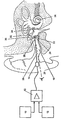
- electrical test signals such as. pure sine tones or broadband signals (noise, etc.) generated, whereby these with regard to the functional parameters (frequency, level, temporal sequences, envelopes etc.) can be set.
- These preprocessed signals are processed with an amplifier 12, which contains a driving output stage corresponding to the selected converter method, amplified and fed to an electromechanical transducer 14.
- Alternative to generation of the test signals by means of the generator part 10 can the signals as in known ones Audiometem also taken from a sound carrier 16 (magnetic tape, compact disc, etc.) and the amplifier 12 are supplied.
- the converter 14 according to all known electromechanical Conversion principles (dynamic, magnetic, piezoelectric, capacitive / dielectric, magnetostrictive) can work, preferably the piezoelectric or capacitive E-field transducer types chosen due to the lack of magnetic interference fields with suitable aids close to the entrance of the external auditory canal 18 of the ear to be examined.
- the external dimensions of this transducer 14 are designed in such a way that the examining person still has a clear view (dashed line of sight 20) through the external auditory canal 18 to the center 22 (umbo) of the eardrum 24 Has.
- the electromechanical converter 14 converts the electrical driver signals into mechanical ones Vibrations around.
- transducer vibrations are on in its longitudinal axis mechanically rigid coupling element 26 transmitted mechanically fixed or by means of a (Not shown) connector connected to the vibrating part of the transducer 14 is.
- the coupling element 26, which is shown in the drawing as a rod-shaped component, makes contact after lowering by the examining person with his face away from the transducer End 28 mechanically with slight pressure the center 22 (umbo) of the eardrum 24.
- the mechanical transducer vibrations via the ossicular chain Transfer hammer 30, anvil 32 and stirrup 34 to the inner ear or the worm 36, to lead to an auditory impression.
- the end 28 of the rod-shaped coupling element 26 is designed and surface-treated by suitable measures that on the one hand after positioning and lowering, slipping off the umbo 22 is avoided and on the other hand, a risk of injury to this eardrum area can be excluded can.
- the rod-shaped coupling element 26 is preferably designed so that it on the one hand in axial direction to avoid mechanical resonances in the listening area if possible has high rigidity and on the other hand manually by the examining person is easily deformable (bendable) to adapt to the light, individual To curvature of the ear canal 18 and thus touching the vibrating Avoid coupling element with areas of the external auditory canal.
- the coupling element 26 is not fixed to the converter 14 connected, but e.g. via a mechanically suitable connector. To this In this way, coupling elements of different lengths for individually different lengths of the outer ear canal can be realized, these different coupling elements cheap are producible and therefore for hygienic reasons during serial examinations as single-use items are executable.
- the overall electromechanical system consisting of transducer 14 and coupling element 26, with its dynamic components that determine the operating behavior
- Dimensions and rigidity are dimensioned so that on the one hand a highly coordinated system is present, i.e. the first mechanical resonance frequency at the upper end of the target Transmission frequency range ( ⁇ 10 kHz). Because of this broadband the system has a short settling time in time behavior, which leads to good impulse transmission behavior of the system.
- the mechanical source impedance of this system are well above the biological load impedance caused by the system Tympanic membrane, ossicular chain and coupled, hydromechanical inner ear is formed to a frequency-independent impression of the transducer and thus coupling element deflection to reach. In this way it is possible to get inter-individual hearing test results to compare, since the stimulus level is then not dependent on the unknown, individual fluctuation of the mechanical (biological) load impedances.
- the module according to the invention can be used as a module of this implant system as amplifier 12 for preoperative assessment of the transmission quality and suitability of the intended Implant system can be used in the subject concerned.
- the device according to the invention can be double-eared with a double version Subjects are used to conduct a simultaneous, binaural hearing test.
Description
Claims (14)
- Gerät zur elektromechanischen Stimulation und Prüfung des Gehörs, gekennzeichnet durch einen elektromechanischen Wandler (14) zum Erzeugen von mechanischen Schwingungen im Audiobereich und ein starres, mechanisches Koppelelement (26) zum Übertragen der mechanischen Schwingungen ohne operativen Eingriff durch den äußeren Gehörgang (18) in direktem mechanischem Kontakt auf das Zentrum (22) des Trommelfells (24) und damit auf den Hammergriff der Gehörknöchelchenkette (30, 32, 34) des Mittelohres, dadurch gekennzeichnet, daß der elektromechanische Wandler (14) in Verbindung mit dem mechanischen Koppelelement (26) so ausgeführt ist, daß die erste mechanische Resonanzfrequenz am oberen Ende des spektralen Übertragungsbereiches von ≥ 10 kHz liegt.
- Stimulations- und Prüfgerät nach Anspruch 1, gekennzeichnet durch mindestens einen elektronischen Signalgenerator (10) und/oder mindestens eine mit Tonträgern wie Magnetbändern oder Compact Discs arbeitende Signalquelle (16) zum Erzeugen von audiologischen Prüf- und Testsignalen sowie durch einen Verstärker (12) mit treibender Endstufe zum Zuführen der audiologischen Prüf- und Testsignale zu dem elektromechanischen Wandler (14).
- Stimulations- und Prüfgerät nach einem der vorhergehenden Ansprüche, dadurch gekennzeichnet, daß der elektromechanische Wandler (14) in einem in den Eingangsbereich des äußeren Gehörgangs (18) einzubringenden Wandlergehäuse untergebracht ist, dessen geometrische Abmessungen so gewählt sind, daß die untersuchende Person auch unter Verwendung eines Mikroskopes freie Sicht auf das das Zentrum (22) des Trommelfells (24) mechanisch kontaktierende Wirkende (28) des Koppelelementes (26) behält.
- Stimulations- und Prüfgerät nach einem der vorhergehenden Ansprüche, dadurch gekennzeichnet, daß das von dem Wandler (14) abgewandte Wirkende (28) des Koppelelements (26) konstruktiv so ausgebildet ist, daß ein verletzungsfreier, mechanischer Kontakt zum Zentrum (22) des Trommelfells (24) gewährleistet ist.
- Stimulations- und Prüfgerät nach einem der vorhergehenden Ansprüche, dadurch gekennzeichnet, daß das Koppelelement (26) als stabförmiges, in axialer Richtung steifes Bauteil ausgeführt ist.
- Stimulations- und Prüfgerät nach einem der vorhergehenden Ansprüche, dadurch gekennzeichnet, daß das Koppelelement (26) manuell leicht biegbar gestaltet ist.
- Stimulations- und Prüfgerät nach einem der vorhergehenden Ansprüche, dadurch gekennzeichnet, daß das Koppelelement (26) über eine mechanische Steckverbindung mit dem Wandler (14) verbunden ist.
- Stimulations- und Prüfgerät nach einem der vorhergehenden Ansprüche, dadurch gekennzeichnet, daß der elektromechanische Wandler (14) so ausgeführt ist, daß seine mechanische Quellimpedanz im gesamten spektralen Übertragungsbereich deutlich größer ist als die mechanische Lastimpedanz, die durch das biologische System Trommelfell (24), Gehörknöchelchenkette (30, 32, 34) und Innenohr (36) gebildet wird.
- Stimulations- und Prüfgerät nach einem der Ansprüche 2 bis 8, dadurch gekennzeichnet, daß der den Wandler (14) treibende Verstärker (12) und der Wandler selbst so ausgelegt sind, daß der Wandler mit Koppelelement (26) im gesamten spektralen, audiologischen Übertragungsbereich bei mechanisch angekoppelter Gehörknöchelchenkette (30, 32, 34) maximale Auslenkungsamplituden im Bereich von 1-5 µm erzeugt, die einem äquivalenten Schalldruckpegel von 120 - 140 dB SPL entsprechen.
- Stimulations- und Prüfgerät nach einem der vorhergehenden Ansprüche, dadurch gekennzeichnet, daß der elektromechanische Wandler (14) durch die konstruktive Gestaltung des Wandlergehäuses akustisch so gekapselt ist, daß das Schallsignal, das durch die schwingenden Wandlerstrukturen abgestrahlt wird, so minimiert ist, daß bei hohen Stimulationspegeln auf eine akustische Vertäubung des kontralateralen, nicht untersuchten Ohres verzichtet werden kann.
- Stimulations- und Prüfgerät nach einem der vorhergehenden Ansprüche, dadurch gekennzeichnet, daß der elektromechanische Wandler (14) auf dem Prinzip der elektrodynamischen, elektromagnetischen, magnetostriktiven, kapazitiven oder piezoelektrischen Wandlung beruht.
- Stimulations- und Prüfgerät nach Anspruch 11, dadurch gekennzeichnet, daß der elektromechanische Wandler (14) nach dem piezoelektrischen Prinzip arbeitet.
- Stimulations- und Prüfgerät nach einem der Ansprüche 2 bis 12, dadurch gekennzeichnet, daß das aus Signalquelle (10, 16), Verstärker (12) und elektromechanischem Wandler (14) mit Koppelelement (26) bestehende System als präoperatives Diagnose- und Demonstrationsgerät der zu erwartenden Übertragungsqualität bei der Applikation teilund vollimplantierbarer Hörgeräte ausgeführt ist.
- Stimulations- und Prüfgerät nach einem der vorhergehenden Ansprüche, dadurch gekennzeichnet, daß das Gerät doppelt ausgeführt ist, um eine simultane, beidohrige Stimulation und Prüfung des Gehörs zu ermöglichen.
Applications Claiming Priority (2)
| Application Number | Priority Date | Filing Date | Title |
|---|---|---|---|
| DE19618961 | 1996-05-10 | ||
| DE19618961A DE19618961B4 (de) | 1996-05-10 | 1996-05-10 | Gerät zur elektromechanischen Stimulation und Prüfung des Gehörs |
Publications (2)
| Publication Number | Publication Date |
|---|---|
| EP0806884A1 EP0806884A1 (de) | 1997-11-12 |
| EP0806884B1 true EP0806884B1 (de) | 2003-09-17 |
Family
ID=7793998
Family Applications (1)
| Application Number | Title | Priority Date | Filing Date |
|---|---|---|---|
| EP97107228A Expired - Lifetime EP0806884B1 (de) | 1996-05-10 | 1997-04-30 | Gerät zur elektromechanischen Stimulation und Prüfung des Gehörs |
Country Status (4)
| Country | Link |
|---|---|
| US (1) | US5833626A (de) |
| EP (1) | EP0806884B1 (de) |
| DE (2) | DE19618961B4 (de) |
| DK (1) | DK0806884T3 (de) |
Families Citing this family (53)
| Publication number | Priority date | Publication date | Assignee | Title |
|---|---|---|---|---|
| DE19527108A1 (de) * | 1995-07-25 | 1997-01-30 | Hans Peter Prof Dr Med Zenner | Ermittlung von Daten über das Hörvermögen |
| DE69739657D1 (de) * | 1996-07-19 | 2009-12-31 | Armand P Neukermans | Biokompatibler, implantierbarer microantrieb für ein hörgerät |
| US5879283A (en) * | 1996-08-07 | 1999-03-09 | St. Croix Medical, Inc. | Implantable hearing system having multiple transducers |
| US6001129A (en) * | 1996-08-07 | 1999-12-14 | St. Croix Medical, Inc. | Hearing aid transducer support |
| US5836863A (en) | 1996-08-07 | 1998-11-17 | St. Croix Medical, Inc. | Hearing aid transducer support |
| US5899847A (en) | 1996-08-07 | 1999-05-04 | St. Croix Medical, Inc. | Implantable middle-ear hearing assist system using piezoelectric transducer film |
| US6315710B1 (en) | 1997-07-21 | 2001-11-13 | St. Croix Medical, Inc. | Hearing system with middle ear transducer mount |
| US5954628A (en) * | 1997-08-07 | 1999-09-21 | St. Croix Medical, Inc. | Capacitive input transducers for middle ear sensing |
| US5993376A (en) * | 1997-08-07 | 1999-11-30 | St. Croix Medical, Inc. | Electromagnetic input transducers for middle ear sensing |
| DE19738587C1 (de) * | 1997-09-03 | 1999-05-27 | Implex Gmbh | Anordnung zum Einstellen und Fixieren der Relativlage zweier Elemente eines aktiven oder passiven Hör-Implantats |
| AU2316099A (en) * | 1998-01-12 | 1999-07-26 | Mdi Instruments, Inc. | Ear examining device with temperature sensor |
| DE19821602C1 (de) * | 1998-05-14 | 2000-04-20 | Univ Dresden Tech | Vibrationsmeßkopf zur Bestimmung der Beweglichkeit der Bestandteile des menschlichen Mittelohrapparates |
| US6137889A (en) * | 1998-05-27 | 2000-10-24 | Insonus Medical, Inc. | Direct tympanic membrane excitation via vibrationally conductive assembly |
| WO1999063785A2 (en) | 1998-06-05 | 1999-12-09 | St. Croix Medical, Inc. | Reduced feedback in implantable hearing assistance systems |
| US6364825B1 (en) | 1998-09-24 | 2002-04-02 | St. Croix Medical, Inc. | Method and apparatus for improving signal quality in implantable hearing systems |
| US7664282B2 (en) * | 1998-11-25 | 2010-02-16 | Insound Medical, Inc. | Sealing retainer for extended wear hearing devices |
| US20060291683A1 (en) * | 1998-11-25 | 2006-12-28 | Insound Medical, Inc. | Sealing retainer for extended wear hearing devices |
| US6940988B1 (en) * | 1998-11-25 | 2005-09-06 | Insound Medical, Inc. | Semi-permanent canal hearing device |
| US7580537B2 (en) * | 1998-11-25 | 2009-08-25 | Insound Medical, Inc. | Sealing retainer for extended wear hearing devices |
| US6496585B1 (en) * | 1999-01-27 | 2002-12-17 | Robert H. Margolis | Adaptive apparatus and method for testing auditory sensitivity |
| DE19914992A1 (de) * | 1999-04-01 | 2000-12-07 | Implex Hear Tech Ag | Implantierbares Hörsystem mit Audiometer |
| US7379555B2 (en) * | 1999-06-08 | 2008-05-27 | Insound Medical, Inc. | Precision micro-hole for extended life batteries |
| US7016504B1 (en) | 1999-09-21 | 2006-03-21 | Insonus Medical, Inc. | Personal hearing evaluator |
| US6940989B1 (en) * | 1999-12-30 | 2005-09-06 | Insound Medical, Inc. | Direct tympanic drive via a floating filament assembly |
| DE10014200C2 (de) * | 2000-03-22 | 2002-02-21 | Implex Hear Tech Ag | Gerät zum elektromechanischen Stimulieren und Prüfen des Gehörs |
| EP1293107A4 (de) * | 2000-06-01 | 2007-03-14 | Otologics Llc | Verfahren und vorrichtung zur leistungsmessung eines implantierbaren mittelohrhörgeräts und zur messung der reaktion eines ein derartigss hörgerät tragenden patienten |
| DE10041725B4 (de) | 2000-08-25 | 2004-04-29 | Phonak Ag | Gerät zur elektromechanischen Stimulation und Prüfung des Gehörs |
| DE10057584A1 (de) * | 2000-11-21 | 2002-06-06 | Implex Ag Hearing Technology I | Gerät zür präoperativen Demonstration implantierbarer Hörsysteme |
| US6730015B2 (en) | 2001-06-01 | 2004-05-04 | Mike Schugt | Flexible transducer supports |
| US6914994B1 (en) | 2001-09-07 | 2005-07-05 | Insound Medical, Inc. | Canal hearing device with transparent mode |
| US7127078B2 (en) | 2001-10-03 | 2006-10-24 | Advanced Bionics Corporation | Implanted outer ear canal hearing aid |
| US6786860B2 (en) | 2001-10-03 | 2004-09-07 | Advanced Bionics Corporation | Hearing aid design |
| US6879695B2 (en) * | 2001-10-03 | 2005-04-12 | Advanced Bionics Corporation | Personal sound link module |
| WO2003037212A2 (en) | 2001-10-30 | 2003-05-08 | Lesinski George S | Implantation method for a hearing aid microactuator implanted into the cochlea |
| US6997864B2 (en) * | 2003-11-03 | 2006-02-14 | Otologics, Llc | Method for obtaining diagnostic information relating to a patient having an implanted transducer |
| US8457336B2 (en) * | 2004-02-05 | 2013-06-04 | Insound Medical, Inc. | Contamination resistant ports for hearing devices |
| US7582052B2 (en) * | 2005-04-27 | 2009-09-01 | Otologics, Llc | Implantable hearing aid actuator positioning |
| US20070003081A1 (en) * | 2005-06-30 | 2007-01-04 | Insound Medical, Inc. | Moisture resistant microphone |
| US7704216B2 (en) * | 2005-08-24 | 2010-04-27 | Audiology Incorporated | Method for assessing the accuracy of test results |
| WO2007147071A2 (en) * | 2006-06-14 | 2007-12-21 | Otologics, Llc | Compressive coupling of an implantable hearing aid actuator to an auditory component |
| EP2076174A4 (de) * | 2006-10-13 | 2012-10-24 | Univ North Carolina | Gerät und verfahren zur akustischen oder mechanischen stimulation einer cochlea und intracochleare aufzeichnung von mechanisch oder akustisch evozierten hörpotentialen in der cochlea |
| EP1968347A3 (de) * | 2007-03-02 | 2011-11-09 | Rion Co., Ltd. | Kontaktvibrator und Hörhilfegerät damit |
| US7722525B2 (en) | 2007-05-24 | 2010-05-25 | Otologics, Llc | Lateral coupling of an implantable hearing aid actuator to an auditory component |
| CN101836463A (zh) * | 2007-08-14 | 2010-09-15 | 声音医药公司 | 用于长期佩戴耳道助听装置的组合话筒和听筒组件 |
| US20110009770A1 (en) * | 2009-07-13 | 2011-01-13 | Margolis Robert H | Audiometric Testing and Calibration Devices and Methods |
| US9313589B2 (en) * | 2011-07-01 | 2016-04-12 | Cochlear Limited | Method and system for configuration of a medical device that stimulates a human physiological system |
| US8808906B2 (en) | 2011-11-23 | 2014-08-19 | Insound Medical, Inc. | Canal hearing devices and batteries for use with same |
| US9604325B2 (en) | 2011-11-23 | 2017-03-28 | Phonak, LLC | Canal hearing devices and batteries for use with same |
| US8761423B2 (en) | 2011-11-23 | 2014-06-24 | Insound Medical, Inc. | Canal hearing devices and batteries for use with same |
| US8682016B2 (en) | 2011-11-23 | 2014-03-25 | Insound Medical, Inc. | Canal hearing devices and batteries for use with same |
| WO2016018200A1 (en) | 2014-07-27 | 2016-02-04 | Sonova Ag | Batteries and battery manufacturing methods |
| CN109662831A (zh) * | 2018-05-23 | 2019-04-23 | 李芝宏 | 一种电子耳膜系统及方法 |
| AU2020311927A1 (en) * | 2019-07-10 | 2021-12-09 | Ohio State Innovation Foundation | Auditory prosthetic devices using early auditory potentials as a microphone and related methods |
Family Cites Families (12)
| Publication number | Priority date | Publication date | Assignee | Title |
|---|---|---|---|---|
| DE337590C (de) * | 1919-09-04 | 1921-06-04 | Bruno Griessmann Dr | Anordnung zur isolierten Untersuchung eines einzelnen Ohres und zur Feststellung einseitiger Taubheit |
| US2164121A (en) * | 1938-05-04 | 1939-06-27 | Pescador Hector | Electric hearing apparatus for the deaf |
| ZA704235B (en) * | 1970-06-22 | 1971-12-29 | Bertrand R | Improvements in communications |
| US3882285A (en) * | 1973-10-09 | 1975-05-06 | Vicon Instr Company | Implantable hearing aid and method of improving hearing |
| DE3121429A1 (de) * | 1981-05-29 | 1983-02-03 | Physik Instrumente (PI) GmbH & Co, 7517 Waldbronn | Piezoelektrischer wandler |
| US4729366A (en) * | 1984-12-04 | 1988-03-08 | Medical Devices Group, Inc. | Implantable hearing aid and method of improving hearing |
| US4850962A (en) * | 1984-12-04 | 1989-07-25 | Medical Devices Group, Inc. | Implantable hearing aid and method of improving hearing |
| DE3918086C1 (de) * | 1989-06-02 | 1990-09-27 | Hortmann Gmbh, 7449 Neckartenzlingen, De | |
| US5176620A (en) * | 1990-10-17 | 1993-01-05 | Samuel Gilman | Hearing aid having a liquid transmission means communicative with the cochlea and method of use thereof |
| US5259032A (en) * | 1990-11-07 | 1993-11-02 | Resound Corporation | contact transducer assembly for hearing devices |
| DE4104358A1 (de) * | 1991-02-13 | 1992-08-20 | Implex Gmbh | Implantierbares hoergeraet zur anregung des innenohres |
| US5430801A (en) * | 1993-12-14 | 1995-07-04 | Hill; Frank C. | Hearing aid |
-
1996
- 1996-05-10 DE DE19618961A patent/DE19618961B4/de not_active Expired - Fee Related
- 1996-10-07 US US08/726,486 patent/US5833626A/en not_active Expired - Lifetime
-
1997
- 1997-04-30 DE DE59710743T patent/DE59710743D1/de not_active Expired - Lifetime
- 1997-04-30 DK DK97107228T patent/DK0806884T3/da active
- 1997-04-30 EP EP97107228A patent/EP0806884B1/de not_active Expired - Lifetime
Also Published As
| Publication number | Publication date |
|---|---|
| US5833626A (en) | 1998-11-10 |
| DK0806884T3 (da) | 2003-12-29 |
| DE59710743D1 (de) | 2003-10-23 |
| EP0806884A1 (de) | 1997-11-12 |
| DE19618961B4 (de) | 2004-09-16 |
| DE19618961A1 (de) | 1997-11-13 |
Similar Documents
| Publication | Publication Date | Title |
|---|---|---|
| EP0806884B1 (de) | Gerät zur elektromechanischen Stimulation und Prüfung des Gehörs | |
| EP1181892B1 (de) | Gerät zur elektromechanischen Stimulation und Prüfung des Gehörs | |
| US5999856A (en) | Implantable hearing assistance system with calibration and auditory response testing | |
| Kemp et al. | A guide to the effective use of otoacoustic emissions | |
| US20200367783A1 (en) | System and method for generating and recording auditory steady-state responses with a speech-like stimulus | |
| CN101636111B (zh) | 用于个体听力的客观测量的系统和方法 | |
| Counter et al. | Hearing loss from the acoustic artifact of the coil used in extracranial magnetic stimulation | |
| EP1041857B1 (de) | Implantierbares Hörsystem mit Audiometer | |
| EP1181950A2 (de) | Implantierbares Hörsystem mit Mitteln zur Messung der Ankopplungsqualität | |
| KR20150129661A (ko) | 청력 검사와 청각 평가 장치 | |
| WO2003099121A8 (en) | System and methods for conducting multiple diagnostic hearing tests | |
| CN102908150B (zh) | 一种复合神经动作电位调谐曲线校准及检测系统 | |
| Mertes et al. | Concurrent measures of contralateral suppression of transient-evoked otoacoustic emissions and of auditory steady-state responses | |
| Schwartz et al. | Spectral characteristics of air and bone conduction transducers used to record the auditory brain stem response | |
| EP3281585B1 (de) | System und verfahren zur erzeugung und aufzeichnung von gehörbereitschaftsreaktionen mit einem sprachähnlichen stimulus | |
| US20090323989A1 (en) | System and method for calibrating an audiometer signal | |
| DE102009052574A1 (de) | Hörgerät mit Simulation eines Hörverlusts und Verfahren zur Simulation eines Hörverlusts | |
| Rasmussen et al. | A new approach for recording distortion product oto-acoustic emissions | |
| Kandzia et al. | Binaural measurement of bone conduction click evoked otoacoustic emissions in adults and infants | |
| Martin | Bone-conducted ultrasonic hearing: can distortion product otoacoustic emissions confirm cochlear involvement? | |
| RU2725746C2 (ru) | Система и способ формирования и записи стабильных слуховых реакций с помощью речеподобного стимула | |
| CA2938690C (en) | A system and method for generating and recording auditory steady-state responses with a speech-like stimulus | |
| Faubion et al. | Effects of contralateral noise on envelope-following responses, auditory-nerve compound action potentials, and otoacoustic emissions measured simultaneously | |
| Bednarska et al. | Advances in hearing prosthetics | |
| Bashford et al. | How broadband speech may avoid neural firing rate saturation at high intensities and maintain intelligibility |
Legal Events
| Date | Code | Title | Description |
|---|---|---|---|
| PUAI | Public reference made under article 153(3) epc to a published international application that has entered the european phase |
Free format text: ORIGINAL CODE: 0009012 |
|
| AK | Designated contracting states |
Kind code of ref document: A1 Designated state(s): CH DE DK FR GB IT LI NL |
|
| 17P | Request for examination filed |
Effective date: 19980112 |
|
| 17Q | First examination report despatched |
Effective date: 20000107 |
|
| RAP1 | Party data changed (applicant data changed or rights of an application transferred) |
Owner name: IMPLEX AKTIENGESELLSCHAFT HEARING TECHNOLOGY |
|
| RAP1 | Party data changed (applicant data changed or rights of an application transferred) |
Owner name: PHONAK AG |
|
| GRAH | Despatch of communication of intention to grant a patent |
Free format text: ORIGINAL CODE: EPIDOS IGRA |
|
| GRAS | Grant fee paid |
Free format text: ORIGINAL CODE: EPIDOSNIGR3 |
|
| GRAA | (expected) grant |
Free format text: ORIGINAL CODE: 0009210 |
|
| AK | Designated contracting states |
Kind code of ref document: B1 Designated state(s): CH DE DK FR GB IT LI NL |
|
| PG25 | Lapsed in a contracting state [announced via postgrant information from national office to epo] |
Ref country code: NL Free format text: LAPSE BECAUSE OF FAILURE TO SUBMIT A TRANSLATION OF THE DESCRIPTION OR TO PAY THE FEE WITHIN THE PRESCRIBED TIME-LIMIT Effective date: 20030917 Ref country code: IT Free format text: LAPSE BECAUSE OF FAILURE TO SUBMIT A TRANSLATION OF THE DESCRIPTION OR TO PAY THE FEE WITHIN THE PRESCRIBED TIME-LIMIT;WARNING: LAPSES OF ITALIAN PATENTS WITH EFFECTIVE DATE BEFORE 2007 MAY HAVE OCCURRED AT ANY TIME BEFORE 2007. THE CORRECT EFFECTIVE DATE MAY BE DIFFERENT FROM THE ONE RECORDED. Effective date: 20030917 |
|
| REG | Reference to a national code |
Ref country code: GB Ref legal event code: FG4D Free format text: NOT ENGLISH |
|
| REG | Reference to a national code |
Ref country code: CH Ref legal event code: EP |
|
| REG | Reference to a national code |
Ref country code: CH Ref legal event code: NV Representative=s name: KELLER & PARTNER PATENTANWAELTE AG |
|
| REF | Corresponds to: |
Ref document number: 59710743 Country of ref document: DE Date of ref document: 20031023 Kind code of ref document: P |
|
| REG | Reference to a national code |
Ref country code: DK Ref legal event code: T3 |
|
| GBT | Gb: translation of ep patent filed (gb section 77(6)(a)/1977) |
Effective date: 20040107 |
|
| NLV1 | Nl: lapsed or annulled due to failure to fulfill the requirements of art. 29p and 29m of the patents act | ||
| ET | Fr: translation filed | ||
| PLBE | No opposition filed within time limit |
Free format text: ORIGINAL CODE: 0009261 |
|
| STAA | Information on the status of an ep patent application or granted ep patent |
Free format text: STATUS: NO OPPOSITION FILED WITHIN TIME LIMIT |
|
| 26N | No opposition filed |
Effective date: 20040618 |
|
| PGFP | Annual fee paid to national office [announced via postgrant information from national office to epo] |
Ref country code: GB Payment date: 20110331 Year of fee payment: 15 Ref country code: FR Payment date: 20110413 Year of fee payment: 15 |
|
| PGFP | Annual fee paid to national office [announced via postgrant information from national office to epo] |
Ref country code: DK Payment date: 20110404 Year of fee payment: 15 |
|
| PGFP | Annual fee paid to national office [announced via postgrant information from national office to epo] |
Ref country code: DE Payment date: 20120430 Year of fee payment: 16 Ref country code: CH Payment date: 20120416 Year of fee payment: 16 |
|
| REG | Reference to a national code |
Ref country code: DK Ref legal event code: EBP |
|
| GBPC | Gb: european patent ceased through non-payment of renewal fee |
Effective date: 20120430 |
|
| REG | Reference to a national code |
Ref country code: FR Ref legal event code: ST Effective date: 20121228 |
|
| PG25 | Lapsed in a contracting state [announced via postgrant information from national office to epo] |
Ref country code: GB Free format text: LAPSE BECAUSE OF NON-PAYMENT OF DUE FEES Effective date: 20120430 |
|
| PG25 | Lapsed in a contracting state [announced via postgrant information from national office to epo] |
Ref country code: FR Free format text: LAPSE BECAUSE OF NON-PAYMENT OF DUE FEES Effective date: 20120430 |
|
| PG25 | Lapsed in a contracting state [announced via postgrant information from national office to epo] |
Ref country code: DK Free format text: LAPSE BECAUSE OF NON-PAYMENT OF DUE FEES Effective date: 20120430 |
|
| REG | Reference to a national code |
Ref country code: CH Ref legal event code: PL |
|
| PG25 | Lapsed in a contracting state [announced via postgrant information from national office to epo] |
Ref country code: LI Free format text: LAPSE BECAUSE OF NON-PAYMENT OF DUE FEES Effective date: 20130430 Ref country code: DE Free format text: LAPSE BECAUSE OF NON-PAYMENT OF DUE FEES Effective date: 20131101 Ref country code: CH Free format text: LAPSE BECAUSE OF NON-PAYMENT OF DUE FEES Effective date: 20130430 |
|
| REG | Reference to a national code |
Ref country code: DE Ref legal event code: R119 Ref document number: 59710743 Country of ref document: DE Effective date: 20131101 |