EP0806663B1 - Apparatus and method for determination of non-hemolyzed levels of occult blood in urine - Google Patents
Apparatus and method for determination of non-hemolyzed levels of occult blood in urine Download PDFInfo
- Publication number
- EP0806663B1 EP0806663B1 EP97107009A EP97107009A EP0806663B1 EP 0806663 B1 EP0806663 B1 EP 0806663B1 EP 97107009 A EP97107009 A EP 97107009A EP 97107009 A EP97107009 A EP 97107009A EP 0806663 B1 EP0806663 B1 EP 0806663B1
- Authority
- EP
- European Patent Office
- Prior art keywords
- reagent pad
- reflectance
- magnitude
- illuminating
- reagent
- Prior art date
- Legal status (The legal status is an assumption and is not a legal conclusion. Google has not performed a legal analysis and makes no representation as to the accuracy of the status listed.)
- Expired - Lifetime
Links
Images

Classifications
-
- G—PHYSICS
- G01—MEASURING; TESTING
- G01N—INVESTIGATING OR ANALYSING MATERIALS BY DETERMINING THEIR CHEMICAL OR PHYSICAL PROPERTIES
- G01N21/00—Investigating or analysing materials by the use of optical means, i.e. using sub-millimetre waves, infrared, visible or ultraviolet light
- G01N21/84—Systems specially adapted for particular applications
- G01N21/8483—Investigating reagent band
-
- G—PHYSICS
- G01—MEASURING; TESTING
- G01N—INVESTIGATING OR ANALYSING MATERIALS BY DETERMINING THEIR CHEMICAL OR PHYSICAL PROPERTIES
- G01N21/00—Investigating or analysing materials by the use of optical means, i.e. using sub-millimetre waves, infrared, visible or ultraviolet light
- G01N21/17—Systems in which incident light is modified in accordance with the properties of the material investigated
- G01N21/47—Scattering, i.e. diffuse reflection
Definitions
- the present invention relates to apparatus and method for performing tests on a sample of body fluid to be analyzed, and more particularly to a reflectance spectroscope and method for determination of non-hemolyzed levels of occult blood in urine.
- a reflectance spectroscope it is useful for various medical diagnostic purposes to utilize a reflectance spectroscope to analyze samples of body fluid, for example, to detect the presence of blood in a person's urine.
- Conventional reflectance spectroscopes like the one disclosed in DE 2 462 716, have been used to detect the presence of blood in a urine sample disposed on a reagent pad. Any blood present in the urine reacts with the reagent on the reagent pad, causing the reagent pad to change color over time to an extent which depends on the concentration of the blood. For example, in the presence of a relatively large concentration of blood, such a reagent pad may change in color from yellow to dark green.
- One prior art reflectance spectroscope detects the concentration of the blood by illuminating a single portion of the reagent pad and detecting, via a conventional reflectance detector, the amount of light received from the reagent pad, which is related to the color of the reagent pad. Based upon the magnitude of the reflectance signal generated by the reflectance detector, the spectroscope assigns the urine sample to one of a number of categories, e.g. a first category corresponding to no blood, a second category corresponding to a small blood concentration, a third category corresponding to a medium blood concentration, and a fourth category corresponding to a large blood concentration.
- a number of categories e.g. a first category corresponding to no blood, a second category corresponding to a small blood concentration, a third category corresponding to a medium blood concentration, and a fourth category corresponding to a large blood concentration.
- the assignment of a urine sample into one of the categories described above has been performed by successively comparing the magnitude of the reflectance signal with each of three threshold levels which define the categories. For example, if the reflectance signal has a magnitude that corresponds to a 10% light reflectance (which would correspond to a dark reagent pad having a large blood concentration), the spectroscope would compare that 10% reflectance signal with the threshold for large blood concentrations, e.g. 15%, and would assign the urine sample to that category.
- a conventional spectroscope is the possibility of miscategorizing the blood concentration in cases where non-hemolyzed blood is present.
- Blood present in a normal urine sample is hemolyzed, which means that the blood is relatively uniformly distributed throughout the urine sample as small blood cell fragments which are visually undetectable.
- the blood is non-hemolyzed, meaning that there are substantially intact red blood cells or relatively large blood cell fragments present which can be visually detected with the unaided eye or with a small amount of magnification.
- a conventional spectroscope may generate a false negative (erroneously reporting the absence of blood) if the concentration of the individual blood cells is small enough.
- the large blood cell fragments could be seen, thus leading the doctor to erroneously believe that the spectroscope was faulty.
- EP 0 743 514 which was published after the priority date of the present application, discloses a method and apparatus for detecting the presence of non-hemolized trace and hemolized occult blood.
- the invention is directed to an apparatus for analyzing a body-fluid sample disposed on a reagent pad.
- the apparatus is provided with means for successively illuminating a plurality of different portions of the reagent pad on which the body-fluid sample is disposed and means for generating a plurality of reflectance signals in response to light received from a corresponding one of the different portions of the reagent pad illuminated by the illuminating means.
- the apparatus is also provided with means for determining whether the magnitude of one of the reflectance signals is substantially different than the magnitude of another of the reflectance signals. Where the body-fluid sample is urine, this capability allows the apparatus to detect the presence of non-hemolyzed blood in the urine sample.
- the illuminating means may successively illuminate a plurality of overlapping portions of the reagent pad, and may successively illuminate at least three different portions of the reagent pad which are linearly offset from each other.
- the apparatus may also be provided with means for determining a decode signal based upon the reflectance signals, and means for comparing the decode signal with a plurality of predetermined thresholds to categorize the body-fluid sample.
- the apparatus may include means for determining a difference between the magnitude of one of the reflectance signals and the magnitude of another of the reflectance signals and means for comparing the difference with a predetermined threshold to detect the presence of non-hemolyzed blood in the urine sample.
- the means for determining the difference may include means for determining which of the reflectance signals has the largest magnitude, means for determining which of the reflectance signals has the smallest magnitude, and means for determining a difference between the largest magnitude and the smallest magnitude of the reflectance signals.
- the invention is also directed to a method of analyzing a urine sample disposed on a reagent pad.
- the method includes the steps of: illuminating a first portion of the reagent pad, detecting light received from the first portion of the reagent pad, and generating a first reflectance signal having a magnitude based on the light detected from the first illuminated portion.
- the method also includes the steps of illuminating a second portion of the reagent pad, detecting light received from the second portion of the reagent pad, and generating a second reflectance signal having a magnitude based on the light detected from the second illuminated portion.
- the method determines whether the magnitude of the first reflectance signal is substantially different than the magnitude of the second reflectance signal.
- the invention is directed to an apparatus for illuminating a body-fluid sample disposed on a reagent pad.
- the apparatus is provided with means for illuminating a first portion of the reagent pad on which the body-fluid sample is disposed, the first portion of the reagent pad having an area that is smaller than the overall area of the reagent pad.
- the apparatus includes means for moving the reagent pad relative to the illuminating means so that the illuminating means illuminates a second portion of the reagent pad different from the first portion of the reagent pad, the second portion of the reagent pad having an area that is smaller than the overall area of the reagent pad.
- the apparatus also includes means for detecting light received from the illuminated portions of the reagent pad.
- Fig. 1 illustrates a reflectance spectroscope 10 for performing various tests, such as urinalysis tests, on a reagent strip.
- the spectroscope 10 has an integral keyboard 12 with a number of entry keys 14 that may be depressed by the user.
- a visual display 16 for displaying various messages relating to the operation of the spectroscope 10 is disposed above the keyboard 12.
- the spectroscope 10 has a front face 17 with an opening 18 formed therein in which a tray 20 for carrying a reagent strip 22 is retractably disposed.
- the tray 20 has a central channel 24 and two side channels 26 formed therein, and the central channel 24 is sized to conform to the shape of the reagent strip 22.
- the reagent strip 22 has a thin, non-reactive substrate 28 on which a number of reagent pads 30 are fixed.
- Each reagent pad 30 is composed of a relatively absorbent material impregnated with a respective reagent, each reagent and reagent pad 30 being associated with a particular test to be performed.
- test to be performed they may include, for example, a test for leukocytes in the urine, a test of the pH of the urine, a test for blood in the urine, etc.
- the pad 30 When each reagent pad 30 comes into contact with a urine sample, the pad changes color over a time period, depending on the reagent used and the characteristics of the urine sample.
- the reagent strip 22 may be, for example, a Multistix® reagent strip commercially available from Bayer Corporation.
- the reagent strip 22 is dipped into a urine sample to be tested so that all of the reagent pads 30 are immersed in the sample. After the side of the reagent strip 22 is blotted to remove excess urine, the strip 22 is placed in the central channel 24 of the tray 20, and after the user presses one of the start keys 14 to initiate testing, the tray 20 is automatically retracted into the spectroscope 10.
- a respective test is performed on each of the reagent pads 30 by illuminating a portion of the reagent pad 30 with white light from a light source and then determining the color of the reagent pad 30 based upon detection of light received from the illuminated portion of the reagent pad 30 at an angle (e.g. 45°) from the upper surface of the pad 30.
- the tray 20 is repositioned relative to the light source so that the next reagent pad 30 to be tested is illuminated.
- the spectroscope 10 When the testing is completed, the spectroscope 10 generates a record of the results, which are displayed on the display 16 and/or printed on a strip of paper 32 via a printer and/or sent to a computer.
- Fig. 3 is a cross-sectional view of an optical system, in the form of a read head 34, for illuminating portions of the reagent pads 30 and for detecting light from the reagent pads 30, and a portion of the tray 20 on which the reagent strip 22 is disposed.
- the read head 34 has a housing with a top wall 36, a bottom wall 38, a side wall 40, an angled wall 42, a planar back wall 44, and a planar front wall (not shown) parallel to the back wall 44.
- An illumination source in the form of a light bulb 46 is supported directly above the reagent pad 30 to be tested via a cylindrical housing portion 48 integrally formed with the top wall 36.
- the lower spherical portion of the light bulb 46 has a concentrating lens integrally formed therein, and the lower spherical surface is acid-etched to provide it with an uneven, diffusing surface so that the shape of the bulb filament does not contribute to non-uniformity of the emitted light.
- the bulb 46 is dynamically fitted to a ceramic base 49 when the bulb 46 is illuminated to ensure that the axial direction in which bulb 46 emits light is substantially parallel to the longitudinal axis of the ceramic base 49.
- the bulb 46 emits light through a circular aperture 50 formed in the top wall 36 to form a cone of light defined by a first edge ray 52 and a second edge ray 54.
- the angled side wall 42 has a rectangular aperture 55 formed therein in which a rectangular detector array 56 is disposed.
- the detector array 56 has four reflectance detectors 57, 58, 59, 60 disposed therein (see Fig. 4), each of which is composed of a conventional colored or IR filter and a conventional silicon detector. Each filter allows light having a distinct wavelength to pass through so that each of the detectors 57-60 is responsive to light of a different wavelength range.
- the four wavelength bands of the filters are: 400-510 nm (nanometers) (blue); 511-586 nm (green); 587-660 nm (red); and 825-855 nm (infrared). Depending on the type of test being performed, one or more of the detectors 57-60 may be used.
- Light passes through a first optical path from the light bulb 46, through a relatively small rectangular aperture 62 formed in the bottom wall 38, to illuminate a relatively small rectangular area of the reagent pad 30 being tested.
- the reagent pad 30 may be moved relative to the aperture 62 so that different rectangular areas of the reagent pad 30 are illuminated.
- the illuminated areas may include a first area indicated by a dotted box 63, a second area indicated by a solid box 64, a third area indicated by a dotted box 65, and a fourth area indicated by a solid box 66.
- the illuminated areas 63-66 are linearly offset with respect to each other, and adjacent areas partially overlap each other.
- a number of irregularly shaped areas 67 representing non-hemolyzed blood cell fragments are also shown in Fig. 5.
- Light passes through a second optical path from the illuminated area on the reagent pad 30, through a first rectangular detection aperture 68 having angled edges 69 formed in the bottom wall 38, through a second rectangular detection aperture 70 having angled edges 71, and through a rectangular aperture 72 formed in the angled wall 42 to a detection area 73 (Fig. 4) in which the four detectors 57-60 are disposed.
- the interior of the read head 34 is provided with an irregularly shaped baffle 74 composed of a first planar wall segment 76, a second planar wall segment 78, and a zig-zag shaped wall segment 80.
- the shape of the baffle 74 is designed to prevent singly-reflected light rays from reaching the reagent pad 30 from the light bulb 46 and to prevent singly-reflected light rays from reaching the detector area 73 from the reagent pad 30.
- All surfaces of the baffle 74 and all interior surfaces of the housing walls 36, 38, 40, 42, 44 are shiny, specular surfaces so that any light incident upon any surface at an angle of incidence is reflected from that surface at an angle of reflection equal to the angle of incidence. This may be accomplished by injection-molding the read head 34 from a metal mold having highly polished molding surfaces.
- the read head 34 is preferably formed of black plastic so that only a small percentage of light, e.g. 5%, incident upon any of its internal surfaces is reflected. Consequently, any light that undergoes at least two reflections from any interior surfaces of the read head 34 is attenuated by at least 99.75%.
- the wall segment 76 has a specular surface 82 that is angled in a direction indicated by a dotted line 84, which intersects the bottom wall 38 at a point just to the left of the aperture 62. Consequently, any light rays emitted by the bulb 46 that impinge upon the surface 82 are reflected to an area to the left of the aperture 62. It should be noted that any such rays are reflected at least twice (in actuality at least three times) before they can pass through the aperture 62. It should also be noted that no light can be reflected from the surface 82 and pass directly through the aperture 62 without further reflection since the surface 82 is not visible when the interior of the read head 34 is viewed from the aperture 62.
- the wall segment 78 has a specular surface 86 angled in a direction indicated by a dotted line 88, which intersects the top wall 36 at a point to the left of the circular opening 50 through which light passes. Consequently, there is no direct path from the light bulb 46 to the surface 86; therefore, any light that is reflected from the surface 86 to the aperture 62 will have undergone at least two (more than two in actuality) reflections from the interior surfaces of the read head 34.
- Fig. 3A is an enlarged view of a portion of read head 34 shown in Fig. 3.
- the zig-zag wall segment 80 has angled surfaces 90-93, each of which is angled in a direction indicated by a respective dotted line. Since all of the dotted lines intersect the bottom wall 38 or the side wall 40 to the left of the aperture 62, no light that impinges upon these surfaces 90-93 directly from the light bulb 46 can be reflected directly to the aperture 62.
- the zig-zag wall segment 80 has two further surfaces 94, 95 (Fig. 3) that are angled so that any light that impinges on those surfaces directly from the bulb 46 is reflected exclusively to the area of the bottom wall 38 to the right sides of the aperture 62.
- the only surfaces from which light rays emitted by the bulb 46 can be singly-reflected and still pass through the aperture 62 are the vertical walls of the aperture 62 itself. However, such singly-reflected light rays constitute an insignificant amount of the total light which passes directly from the light bulb 46 to the reagent pad 30 without reflection. There is also a singly-reflected light path from the bulb 46 to the walls 40 or 44 to the aperture 62. But because the bulb 46 concentrates light in a forward direction within the cone defined by rays 52 and 54, the amount of light going through the aperture 62 from this path is insignificant.
- the second optical path from the reagent pad 30 to the detector area 73 (Fig. 4), is generally indicated by a pair of dotted lines 96, 98.
- the side of the zig-zag wall segment 80 which is disposed adjacent the second optical path has a plurality of planar, specular surfaces 100, 101, 102 which are angled in a direction indicated by a number of corresponding dotted lines (shown in Fig. 3) which intersect the angled side wall 42 at a point to the lower right of the detector area 73.
- any light rays that impinge upon these surfaces 100-102 directly from the reagent pad 30 without reflection cannot reach the detector area 73 without at least one more reflection, and thus any such light rays will be attenuated by at least 99.75%.
- the side of the zig-zag wall segment 80 which is disposed adjacent the second optical path has a plurality of planar, specular surfaces 103, 104 (Fig. 3A) which are angled so that no light rays from the reagent pad 30 can reach the surfaces 103, 104 directly without at least one reflection. Consequently, any light rays that impinge upon these surfaces 103-104 will already have undergone at least one reflection, and therefore any such light rays that eventually reach the detector area 73 will be reflected at least twice and thus be attenuated by at least 99.75%.
- the wall surfaces 100 and 103 join at an edge 105, and the wall surfaces 101 and 104 join at an edge 106, the edges 105, 106 being substantially aligned with a respective edge of the detection area 73, and the edges 69, 71 of the detection apertures 68, 70 are aligned with the edges of the detection area 73.
- Fig. 6 is a block diagram of the electronics and other components of the spectroscope 10.
- the operation of the spectroscope 10 is controlled by a microcontroller 200 which has a microprocessor 202, a random-access memory (RAM) 204, a read-only memory (ROM) 206, and an input/output (I/O) circuit 208, all of which are interconnected via an address/data bus 210.
- the microcontroller 200 which may be a conventional microcontroller such as a DS2253T microcontroller commercially available from Vallas Semiconductor, may incorporate a driver circuit 212 connected to the I/O circuit 208 for driving a printer 214.
- the microcontroller 200 controls the movement of the reagent strip tray 20 via a conventional positioner 220 mechanically coupled to the tray 20 and a motor 222, such as a stepping motor, that is driven by drive signals generated by a driver circuit 224 connected to the I/O circuit 208 via an electrical line 226.
- the microcontroller 200 selectively turns on the light bulb 46 via a switch 227 connected to the I/O circuit 208 via an electrical line 229.
- the light bulb 46 is turned on one second prior to the performance of a test so that it will be sufficiently warmed up. If the light bulb 46 is not needed to provide illumination within the next one-second period following a test, it is turned off to conserve its life.
- Each of the detectors 57-60 of the detector array 56 may generate an electrical reflectance signal on one of a number of electrical lines 228. Each reflectance signal has a magnitude that depends on the amount of light detected by the associated detector.
- the microcontroller 200 can selectively read any one of the reflectance signals by transmitting a select signal to a multiplexer 230 via a line 232. The multiplexer 230 then transmits the selected reflectance signal to an amplifier 234 and an analog-to-digital (A/D) converter 236, which transmits the binary signal corresponding to the analog reflectance signal output by the amplifier 234 to the microcontroller 200 via a line 238 connected to the I/O circuit 208.
- A/D analog-to-digital
- the operation of the spectroscope 10 is controlled by a computer program stored in the ROM 206 and executed by the microprocessor 202.
- a flowchart of a test routine 300 which relates to the detection of blood in the urine is shown in Fig. 7.
- the reagent pad 30 having the reagent which changes color in response to the presence of blood is positioned directly below the light bulb 46.
- the detector having the red filter is used for urinalysis testing of the reagent pad 30 for the blood test.
- the amount of light sensed by the detector from the reagent pad 30 is inversely related to the amount of blood present in the urine sample on the reagent pad.
- a relatively large blood concentration will cause the reagent pad 30 to turn from yellow to green. Since the color green is darker and absorbs more light than the color yellow, relatively large blood concentrations will cause the red-filter detector to detect a relatively small amount of light.
- the red-filter detector For each of a plurality of illuminated portions on the reagent pad 30, the red-filter detector generates an electrical reflectance signal having a magnitude directly proportional to the amount of light sensed by the detector from that portion. Based upon the magnitudes of the reflectance signals, the spectroscope 10 associates the urine sample with one of six categories: no blood present, blood trace present, non-hemolyzed blood trace present, a relatively small blood concentration present, a medium blood concentration present, or a relatively large blood concentration present.
- the test routine 300 shown in Fig. 7 may be used to perform a single urinalysis test.
- steps 301-304 cause four reflectance readings of the reagent pad 30 to be made, each reading corresponding to a different one of the illuminated portions 63-66 of the reagent pad 30 (Fig. 5).
- the light bulb 46 is turned on to illuminate a first portion of the reagent pad 30, such as the portion 63 shown in Fig. 5.
- the reflectance signal generated by the red-filter detector is "read” by transmitting it through the multiplexer 230 to the amplifier 234, the A/D converter 236, the I/O circuit 208, and the RAM 204 where its value is stored.
- step 304 if four readings have not been made, the program branches back to step 301 where a different portion of the reagent pad 30 is illuminated, such as the portion 64, and to step 302, where the reflectance reading generated by the detector is read and stored in the RAM 204. Steps 301-302 are repeated until four readings have been taken.
- the program branches to step 308 where a decode reading is determined.
- the decode reading is used to categorize the urine sample into one of three blood concentration categories: large blood concentration, medium blood concentration, or small blood concentration.
- the decode reading may be determined in a number of different ways, such as by taking the average of all four reflectance readings and assigning the average value to the decode reading. Alternatively, the reflectance reading that was taken from a central portion of the reagent pad 30, such as either one of the portions 64, 65 shown in Fig. 5, could be used as the decode reading.
- step 310 if the value of the decode reading is less than a threshold T1, such as 10.3% reflectance, the program branches to step 312 where the urine sample is categorized as having a relatively large blood concentration, which fact is stored in the RAM 204.
- step 314 if the decode reading is less than a threshold T2, such as 19.7% reflectance, the program branches to step 316 where the urine sample is categorized as having a medium blood concentration. If the program reaches step 316, then the decode reading will have a value between the T2 and T3 thresholds (e.g. between 19.7% and 29.1% reflectance), in which case the program will branch to step 318 where the urine sample is categorized as having a relatively small blood concentration.
- the program branches to step 320, where it determines whether at least three of the readings are greater than a threshold T4 (such as 56.0% reflectance), in which case the program branches to step 322 where the urine sample is categorized as being "negative" or having no blood present.
- a threshold T4 such as 56.0% reflectance
- the urine sample is considered to have a trace amount of blood present.
- This trace amount of blood can be composed of either hemolyzed blood or non-hemolyzed blood.
- the four reflectance readings can vary substantially in value, depending upon whether the blood cell fragments 67 are present within the illuminated portion.
- the illuminated portion 65 covers an area which completely encompasses one blood cell fragment 67 and parts of two others, whereas the illuminated portion 66 covers an area which encompasses no blood cell fragments 67. Consequently, the value of the reflectance reading associated with the illuminated portion 65 would be substantially different than the value of the reflectance reading associated with the illuminated portion 66.
- the program determines the difference between the largest and smallest of the four reflectance reading values.
- a predetermined value K such as 2.5% reflectance
- the program branches to step 330 where the urine sample is categorized as having a trace amount of blood.
- the category to which the urine sample was assigned (at one of steps 312, 316, 318, 322, 328 or 330) is output, such as by generating a printed record of the category and/or displaying the category on the visual display 16.
Description
- The present invention relates to apparatus and method for performing tests on a sample of body fluid to be analyzed, and more particularly to a reflectance spectroscope and method for determination of non-hemolyzed levels of occult blood in urine.
- It is useful for various medical diagnostic purposes to utilize a reflectance spectroscope to analyze samples of body fluid, for example, to detect the presence of blood in a person's urine. Conventional reflectance spectroscopes, like the one disclosed in
DE 2 462 716, have been used to detect the presence of blood in a urine sample disposed on a reagent pad. Any blood present in the urine reacts with the reagent on the reagent pad, causing the reagent pad to change color over time to an extent which depends on the concentration of the blood. For example, in the presence of a relatively large concentration of blood, such a reagent pad may change in color from yellow to dark green. - One prior art reflectance spectroscope detects the concentration of the blood by illuminating a single portion of the reagent pad and detecting, via a conventional reflectance detector, the amount of light received from the reagent pad, which is related to the color of the reagent pad. Based upon the magnitude of the reflectance signal generated by the reflectance detector, the spectroscope assigns the urine sample to one of a number of categories, e.g. a first category corresponding to no blood, a second category corresponding to a small blood concentration, a third category corresponding to a medium blood concentration, and a fourth category corresponding to a large blood concentration.
- The assignment of a urine sample into one of the categories described above has been performed by successively comparing the magnitude of the reflectance signal with each of three threshold levels which define the categories. For example, if the reflectance signal has a magnitude that corresponds to a 10% light reflectance (which would correspond to a dark reagent pad having a large blood concentration), the spectroscope would compare that 10% reflectance signal with the threshold for large blood concentrations, e.g. 15%, and would assign the urine sample to that category.
- One disadvantage of such a conventional spectroscope is the possibility of miscategorizing the blood concentration in cases where non-hemolyzed blood is present. Blood present in a normal urine sample is hemolyzed, which means that the blood is relatively uniformly distributed throughout the urine sample as small blood cell fragments which are visually undetectable. In certain cases, such as in highly concentrated urine, the blood is non-hemolyzed, meaning that there are substantially intact red blood cells or relatively large blood cell fragments present which can be visually detected with the unaided eye or with a small amount of magnification.
- When a relatively small amount of non-hemolyzed blood is present in a urine sample, a conventional spectroscope may generate a false negative (erroneously reporting the absence of blood) if the concentration of the individual blood cells is small enough. However, if that same urine sample on the reagent pad were visually inspected by a doctor, the large blood cell fragments could be seen, thus leading the doctor to erroneously believe that the spectroscope was faulty.
- In line with the above considerations, EP 0 743 514, which was published after the priority date of the present application, discloses a method and apparatus for detecting the presence of non-hemolized trace and hemolized occult blood.
- The problems are solved by apparatus according to
claims claim 7. - The invention is directed to an apparatus for analyzing a body-fluid sample disposed on a reagent pad. The apparatus is provided with means for successively illuminating a plurality of different portions of the reagent pad on which the body-fluid sample is disposed and means for generating a plurality of reflectance signals in response to light received from a corresponding one of the different portions of the reagent pad illuminated by the illuminating means. The apparatus is also provided with means for determining whether the magnitude of one of the reflectance signals is substantially different than the magnitude of another of the reflectance signals. Where the body-fluid sample is urine, this capability allows the apparatus to detect the presence of non-hemolyzed blood in the urine sample.
- The illuminating means may successively illuminate a plurality of overlapping portions of the reagent pad, and may successively illuminate at least three different portions of the reagent pad which are linearly offset from each other. The apparatus may also be provided with means for determining a decode signal based upon the reflectance signals, and means for comparing the decode signal with a plurality of predetermined thresholds to categorize the body-fluid sample.
- The apparatus may include means for determining a difference between the magnitude of one of the reflectance signals and the magnitude of another of the reflectance signals and means for comparing the difference with a predetermined threshold to detect the presence of non-hemolyzed blood in the urine sample. The means for determining the difference may include means for determining which of the reflectance signals has the largest magnitude, means for determining which of the reflectance signals has the smallest magnitude, and means for determining a difference between the largest magnitude and the smallest magnitude of the reflectance signals.
- The invention is also directed to a method of analyzing a urine sample disposed on a reagent pad. The method includes the steps of: illuminating a first portion of the reagent pad, detecting light received from the first portion of the reagent pad, and generating a first reflectance signal having a magnitude based on the light detected from the first illuminated portion. The method also includes the steps of illuminating a second portion of the reagent pad, detecting light received from the second portion of the reagent pad, and generating a second reflectance signal having a magnitude based on the light detected from the second illuminated portion. The method determines whether the magnitude of the first reflectance signal is substantially different than the magnitude of the second reflectance signal.
- In another aspect, the invention is directed to an apparatus for illuminating a body-fluid sample disposed on a reagent pad. The apparatus is provided with means for illuminating a first portion of the reagent pad on which the body-fluid sample is disposed, the first portion of the reagent pad having an area that is smaller than the overall area of the reagent pad. The apparatus includes means for moving the reagent pad relative to the illuminating means so that the illuminating means illuminates a second portion of the reagent pad different from the first portion of the reagent pad, the second portion of the reagent pad having an area that is smaller than the overall area of the reagent pad. The apparatus also includes means for detecting light received from the illuminated portions of the reagent pad.
- These and other features and advantages of the present invention will be apparent to those of ordinary skill in the art in view of the detailed description of the preferred embodiment, which is made with reference to the drawings, a brief description of which is provided below.
-
- Fig. 1 is a perspective view of a reflectance spectroscope which may be used to perform various tests of a body fluid sample disposed on a reagent strip;
- Fig. 2 is a perspective view of a reagent strip and a reagent tray used with the spectroscope of Fig. 1;
- Fig. 3 is a cross-sectional view of a read head used in the spectroscope;
- Fig. 3A is an enlarged view of a portion of the read head shown in Fig. 3;
- Fig. 4 is a schematic view of a detector element used in the spectroscope;
- Fig. 5 is an enlarged view of a reagent pad and a number of illuminated areas on the reagent pad;
- Fig. 6 is a block diagram of the electronics of the spectroscope of Fig. 1; and
- Fig. 7 is a flowchart of a computer program routine that may be used to detect trace levels of non-hemolyzed blood in a urine sample analyzed by the spectroscope.
-
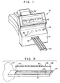
- Fig. 1 illustrates a
reflectance spectroscope 10 for performing various tests, such as urinalysis tests, on a reagent strip. Thespectroscope 10 has anintegral keyboard 12 with a number ofentry keys 14 that may be depressed by the user. Avisual display 16 for displaying various messages relating to the operation of thespectroscope 10 is disposed above thekeyboard 12. Referring to Figs. 1 and 2, thespectroscope 10 has afront face 17 with anopening 18 formed therein in which atray 20 for carrying areagent strip 22 is retractably disposed. Thetray 20 has acentral channel 24 and twoside channels 26 formed therein, and thecentral channel 24 is sized to conform to the shape of thereagent strip 22. - The
reagent strip 22 has a thin,non-reactive substrate 28 on which a number ofreagent pads 30 are fixed. Eachreagent pad 30 is composed of a relatively absorbent material impregnated with a respective reagent, each reagent andreagent pad 30 being associated with a particular test to be performed. When urinalysis tests are performed, they may include, for example, a test for leukocytes in the urine, a test of the pH of the urine, a test for blood in the urine, etc. When eachreagent pad 30 comes into contact with a urine sample, the pad changes color over a time period, depending on the reagent used and the characteristics of the urine sample. Thereagent strip 22 may be, for example, a Multistix® reagent strip commercially available from Bayer Corporation. - To perform urinalysis testing, the
reagent strip 22 is dipped into a urine sample to be tested so that all of thereagent pads 30 are immersed in the sample. After the side of thereagent strip 22 is blotted to remove excess urine, thestrip 22 is placed in thecentral channel 24 of thetray 20, and after the user presses one of thestart keys 14 to initiate testing, thetray 20 is automatically retracted into thespectroscope 10. - A respective test is performed on each of the
reagent pads 30 by illuminating a portion of thereagent pad 30 with white light from a light source and then determining the color of thereagent pad 30 based upon detection of light received from the illuminated portion of thereagent pad 30 at an angle (e.g. 45°) from the upper surface of thepad 30. After each test is performed, thetray 20 is repositioned relative to the light source so that thenext reagent pad 30 to be tested is illuminated. When the testing is completed, thespectroscope 10 generates a record of the results, which are displayed on thedisplay 16 and/or printed on a strip ofpaper 32 via a printer and/or sent to a computer. - Fig. 3 is a cross-sectional view of an optical system, in the form of a
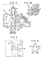
read head 34, for illuminating portions of thereagent pads 30 and for detecting light from thereagent pads 30, and a portion of thetray 20 on which thereagent strip 22 is disposed. Referring to Fig. 3, theread head 34 has a housing with a top wall 36, abottom wall 38, aside wall 40, anangled wall 42, aplanar back wall 44, and a planar front wall (not shown) parallel to theback wall 44. An illumination source in the form of alight bulb 46 is supported directly above thereagent pad 30 to be tested via acylindrical housing portion 48 integrally formed with the top wall 36. - The lower spherical portion of the
light bulb 46 has a concentrating lens integrally formed therein, and the lower spherical surface is acid-etched to provide it with an uneven, diffusing surface so that the shape of the bulb filament does not contribute to non-uniformity of the emitted light. When manufactured, thebulb 46 is dynamically fitted to aceramic base 49 when thebulb 46 is illuminated to ensure that the axial direction in whichbulb 46 emits light is substantially parallel to the longitudinal axis of theceramic base 49. Thebulb 46 emits light through acircular aperture 50 formed in the top wall 36 to form a cone of light defined by afirst edge ray 52 and asecond edge ray 54. - The
angled side wall 42 has arectangular aperture 55 formed therein in which arectangular detector array 56 is disposed. Thedetector array 56 has fourreflectance detectors - Light passes through a first optical path from the
light bulb 46, through a relatively smallrectangular aperture 62 formed in thebottom wall 38, to illuminate a relatively small rectangular area of thereagent pad 30 being tested. Thereagent pad 30 may be moved relative to theaperture 62 so that different rectangular areas of thereagent pad 30 are illuminated. - Referring to Fig. 5, the illuminated areas may include a first area indicated by a dotted
box 63, a second area indicated by asolid box 64, a third area indicated by a dottedbox 65, and a fourth area indicated by asolid box 66. Although shown slightly vertically offset in Fig. 5 so that each box can be distinctly seen, the illuminated areas 63-66 are linearly offset with respect to each other, and adjacent areas partially overlap each other. A number of irregularly shapedareas 67 representing non-hemolyzed blood cell fragments are also shown in Fig. 5. - Light passes through a second optical path from the illuminated area on the
reagent pad 30, through a first rectangular detection aperture 68 having anglededges 69 formed in thebottom wall 38, through a secondrectangular detection aperture 70 having anglededges 71, and through arectangular aperture 72 formed in theangled wall 42 to a detection area 73 (Fig. 4) in which the four detectors 57-60 are disposed. - The interior of the read
head 34 is provided with an irregularly shapedbaffle 74 composed of a firstplanar wall segment 76, a secondplanar wall segment 78, and a zig-zag shapedwall segment 80. The shape of thebaffle 74 is designed to prevent singly-reflected light rays from reaching thereagent pad 30 from thelight bulb 46 and to prevent singly-reflected light rays from reaching thedetector area 73 from thereagent pad 30. - All surfaces of the
baffle 74 and all interior surfaces of thehousing walls head 34 from a metal mold having highly polished molding surfaces. The readhead 34 is preferably formed of black plastic so that only a small percentage of light, e.g. 5%, incident upon any of its internal surfaces is reflected. Consequently, any light that undergoes at least two reflections from any interior surfaces of the readhead 34 is attenuated by at least 99.75%. - Referring to Fig. 3, the
wall segment 76 has aspecular surface 82 that is angled in a direction indicated by a dotted line 84, which intersects thebottom wall 38 at a point just to the left of theaperture 62. Consequently, any light rays emitted by thebulb 46 that impinge upon thesurface 82 are reflected to an area to the left of theaperture 62. It should be noted that any such rays are reflected at least twice (in actuality at least three times) before they can pass through theaperture 62. It should also be noted that no light can be reflected from thesurface 82 and pass directly through theaperture 62 without further reflection since thesurface 82 is not visible when the interior of the readhead 34 is viewed from theaperture 62. - The
wall segment 78 has aspecular surface 86 angled in a direction indicated by a dotted line 88, which intersects the top wall 36 at a point to the left of thecircular opening 50 through which light passes. Consequently, there is no direct path from thelight bulb 46 to thesurface 86; therefore, any light that is reflected from thesurface 86 to theaperture 62 will have undergone at least two (more than two in actuality) reflections from the interior surfaces of the readhead 34. - Fig. 3A is an enlarged view of a portion of
read head 34 shown in Fig. 3. Referring to Figs. 3 and 3A, the zig-zag wall segment 80 has angled surfaces 90-93, each of which is angled in a direction indicated by a respective dotted line. Since all of the dotted lines intersect thebottom wall 38 or theside wall 40 to the left of theaperture 62, no light that impinges upon these surfaces 90-93 directly from thelight bulb 46 can be reflected directly to theaperture 62. The zig-zag wall segment 80 has two further surfaces 94, 95 (Fig. 3) that are angled so that any light that impinges on those surfaces directly from thebulb 46 is reflected exclusively to the area of thebottom wall 38 to the right sides of theaperture 62. - The only surfaces from which light rays emitted by the
bulb 46 can be singly-reflected and still pass through theaperture 62 are the vertical walls of theaperture 62 itself. However, such singly-reflected light rays constitute an insignificant amount of the total light which passes directly from thelight bulb 46 to thereagent pad 30 without reflection. There is also a singly-reflected light path from thebulb 46 to thewalls aperture 62. But because thebulb 46 concentrates light in a forward direction within the cone defined byrays aperture 62 from this path is insignificant. - The second optical path, from the
reagent pad 30 to the detector area 73 (Fig. 4), is generally indicated by a pair ofdotted lines 96, 98. The side of the zig-zag wall segment 80 which is disposed adjacent the second optical path has a plurality of planar,specular surfaces angled side wall 42 at a point to the lower right of thedetector area 73. Consequently, any light rays that impinge upon these surfaces 100-102 directly from thereagent pad 30 without reflection cannot reach thedetector area 73 without at least one more reflection, and thus any such light rays will be attenuated by at least 99.75%. - The side of the zig-
zag wall segment 80 which is disposed adjacent the second optical path has a plurality of planar,specular surfaces 103, 104 (Fig. 3A) which are angled so that no light rays from thereagent pad 30 can reach thesurfaces detector area 73 will be reflected at least twice and thus be attenuated by at least 99.75%. - The wall surfaces 100 and 103 join at an edge 105, and the wall surfaces 101 and 104 join at an edge 106, the edges 105, 106 being substantially aligned with a respective edge of the
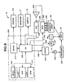
detection area 73, and theedges detection apertures 68, 70 are aligned with the edges of thedetection area 73. - Fig. 6 is a block diagram of the electronics and other components of the
spectroscope 10. Referring to Fig. 6, the operation of thespectroscope 10 is controlled by amicrocontroller 200 which has amicroprocessor 202, a random-access memory (RAM) 204, a read-only memory (ROM) 206, and an input/output (I/O)circuit 208, all of which are interconnected via an address/data bus 210. Themicrocontroller 200, which may be a conventional microcontroller such as a DS2253T microcontroller commercially available from Vallas Semiconductor, may incorporate adriver circuit 212 connected to the I/O circuit 208 for driving aprinter 214. - The
microcontroller 200 controls the movement of thereagent strip tray 20 via aconventional positioner 220 mechanically coupled to thetray 20 and amotor 222, such as a stepping motor, that is driven by drive signals generated by adriver circuit 224 connected to the I/O circuit 208 via anelectrical line 226. - The
microcontroller 200 selectively turns on thelight bulb 46 via aswitch 227 connected to the I/O circuit 208 via anelectrical line 229. Thelight bulb 46 is turned on one second prior to the performance of a test so that it will be sufficiently warmed up. If thelight bulb 46 is not needed to provide illumination within the next one-second period following a test, it is turned off to conserve its life. - Each of the detectors 57-60 of the
detector array 56 may generate an electrical reflectance signal on one of a number ofelectrical lines 228. Each reflectance signal has a magnitude that depends on the amount of light detected by the associated detector. Themicrocontroller 200 can selectively read any one of the reflectance signals by transmitting a select signal to amultiplexer 230 via aline 232. Themultiplexer 230 then transmits the selected reflectance signal to anamplifier 234 and an analog-to-digital (A/D)converter 236, which transmits the binary signal corresponding to the analog reflectance signal output by theamplifier 234 to themicrocontroller 200 via aline 238 connected to the I/O circuit 208. - The operation of the
spectroscope 10 is controlled by a computer program stored in theROM 206 and executed by themicroprocessor 202. A flowchart of atest routine 300 which relates to the detection of blood in the urine is shown in Fig. 7. When a urinalysis test is performed, thereagent pad 30 having the reagent which changes color in response to the presence of blood is positioned directly below thelight bulb 46. The detector having the red filter is used for urinalysis testing of thereagent pad 30 for the blood test. - The amount of light sensed by the detector from the
reagent pad 30 is inversely related to the amount of blood present in the urine sample on the reagent pad. A relatively large blood concentration will cause thereagent pad 30 to turn from yellow to green. Since the color green is darker and absorbs more light than the color yellow, relatively large blood concentrations will cause the red-filter detector to detect a relatively small amount of light. - For each of a plurality of illuminated portions on the
reagent pad 30, the red-filter detector generates an electrical reflectance signal having a magnitude directly proportional to the amount of light sensed by the detector from that portion. Based upon the magnitudes of the reflectance signals, thespectroscope 10 associates the urine sample with one of six categories: no blood present, blood trace present, non-hemolyzed blood trace present, a relatively small blood concentration present, a medium blood concentration present, or a relatively large blood concentration present. - The
test routine 300 shown in Fig. 7 may be used to perform a single urinalysis test. Referring to Fig. 7, steps 301-304 cause four reflectance readings of thereagent pad 30 to be made, each reading corresponding to a different one of the illuminated portions 63-66 of the reagent pad 30 (Fig. 5). Atstep 301, thelight bulb 46 is turned on to illuminate a first portion of thereagent pad 30, such as theportion 63 shown in Fig. 5. Then atstep 302, the reflectance signal generated by the red-filter detector is "read" by transmitting it through themultiplexer 230 to theamplifier 234, the A/D converter 236, the I/O circuit 208, and theRAM 204 where its value is stored. Atstep 304, if four readings have not been made, the program branches back to step 301 where a different portion of thereagent pad 30 is illuminated, such as theportion 64, and to step 302, where the reflectance reading generated by the detector is read and stored in theRAM 204. Steps 301-302 are repeated until four readings have been taken. - At
step 306, if each of the four readings is less than a threshold T3 (e.g. 29.1% reflectance), the program branches to step 308 where a decode reading is determined. The decode reading is used to categorize the urine sample into one of three blood concentration categories: large blood concentration, medium blood concentration, or small blood concentration. Atstep 308, the decode reading may be determined in a number of different ways, such as by taking the average of all four reflectance readings and assigning the average value to the decode reading. Alternatively, the reflectance reading that was taken from a central portion of thereagent pad 30, such as either one of theportions - At
step 310, if the value of the decode reading is less than a threshold T1, such as 10.3% reflectance, the program branches to step 312 where the urine sample is categorized as having a relatively large blood concentration, which fact is stored in theRAM 204. Atstep 314, if the decode reading is less than a threshold T2, such as 19.7% reflectance, the program branches to step 316 where the urine sample is categorized as having a medium blood concentration. If the program reachesstep 316, then the decode reading will have a value between the T2 and T3 thresholds (e.g. between 19.7% and 29.1% reflectance), in which case the program will branch to step 318 where the urine sample is categorized as having a relatively small blood concentration. - If not all four reflectance readings were less than the T3 threshold as determined at
step 306, the program branches to step 320, where it determines whether at least three of the readings are greater than a threshold T4 (such as 56.0% reflectance), in which case the program branches to step 322 where the urine sample is categorized as being "negative" or having no blood present. - If the program reaches step 324 (in which case at least two of the reflectance readings were between the T3 and T4 thresholds as determined at
steps 306, 320), then the urine sample is considered to have a trace amount of blood present. This trace amount of blood can be composed of either hemolyzed blood or non-hemolyzed blood. - Referring to Fig. 5, when non-hemolyzed blood cell fragments 67 come into contact with the
reagent pad 30, they appear to be dark splotches, whereas the remaining portions of thereagent pad 30 appear to be light in color. Consequently, the four reflectance readings, each of which is taken from one of the illuminated portions 63-66, can vary substantially in value, depending upon whether the blood cell fragments 67 are present within the illuminated portion. For example, the illuminatedportion 65 covers an area which completely encompasses oneblood cell fragment 67 and parts of two others, whereas the illuminatedportion 66 covers an area which encompasses no blood cell fragments 67. Consequently, the value of the reflectance reading associated with the illuminatedportion 65 would be substantially different than the value of the reflectance reading associated with the illuminatedportion 66. - Referring to Fig. 7, at
step 324 the program determines the difference between the largest and smallest of the four reflectance reading values. Atstep 326, if that difference is greater than a predetermined value K (such as 2.5% reflectance), it is assumed that non-hemolyzed blood is present, and the program branches to step 328 where the urine sample is categorized as having a trace amount of non-hemolyzed blood. - If the difference between the largest and smallest reflectance readings is not greater than the value K as determined at step 326 (meaning that all four reflectance readings have substantially the same values), the program branches to step 330 where the urine sample is categorized as having a trace amount of blood.
- At
step 332, the category to which the urine sample was assigned (at one ofsteps visual display 16. - Modifications and alternative embodiments of the invention will be apparent to those skilled in the art in view of the foregoing description. This description is to be construed as illustrative only, and is for the purpose of teaching those skilled in the art the best mode of carrying out the invention. The details of the structure and method may be varied substantially without departing from the invention, and the exclusive use of all modifications which come within the scope of the appended claims is reserved.
Claims (10)
- An apparatus for analyzing a urine sample disposed on a reagent pad to detect non-hemolyzed levels of occult blood in said urine sample, said apparatus comprising:means for successively illuminating a plurality of different portions of said reagent pad on which said urine sample is disposed;means for detecting light received from said reagent pad, said detecting means generating a plurality of reflectance signals each having a magnitude, each of said reflectance signals being generated in response to light received from a corresponding one of said different portions of said reagent pad illuminated by said illuminating means;means for determining a difference between said magnitude of one of said reflectance signals and said magnitude of another of said reflectance signals; andmeans for comparing said difference with a predetermined threshold to detect the presence of non-hemolyzed blood in said urine sample.
- An apparatus as defined in claim 1 wherein said illuminating means comprises:a light bulb; andmeans for moving said light bulb relative to said reagent pad.
- An apparatus as defined in claim 2 additionally comprising a tray in which said reagent pad is disposed, wherein said light bulb is disposed in a fixed position and wherein said means for moving said light bulb relative to said reagent pad comprises means for moving said tray.
- An apparatus for analyzing a body-fluid sample disposed on a reagent pad, said apparatus comprising:means for successively illuminating a plurality of different portions of said reagent pad on which said body-fluid sample is disposed;means for detecting light received from said reagent pad, said detecting means generating a plurality of reflectance signals each having a magnitude, each of said reflectance signals being generated in response to light received from a corresponding one of said different portions of said reagent pad illuminated by said illuminating means; andmeans for determining whether said magnitude of one of said reflectance signals is substantially different than said magnitude of another of said reflectance signals.
- An apparatus as defined in claim 4 additionally comprising:means for determining a decode signal based upon said reflectance signals; andmeans for comparing said decode signal with a plurality of predetermined thresholds to categorize said body-fluid sample.
- An apparatus as defined in claim 5 wherein said means for determining a decode signal comprises means for selecting one of said reflectance signals as said decode signal.
- A method of analyzing a urine sample disposed on a reagent pad, said method comprising the steps of:(a) illuminating a first portion of said reagent pad;(b) detecting light received from said first portion of said reagent pad;(c) generating a first reflectance signal having a magnitude based on said light detected during said step (b);(d) illuminating a second portion of said reagent pad, said second portion being different from said first portion;(e) detecting light received from said second portion of said reagent pad;(f) generating a second reflectance signal having a magnitude based on said light detected during said step (e); and(g) determining whether said magnitude of said first reflectance signal is substantially different than said magnitude of said second reflectance signal.
- A method as defined in claim 7 wherein said step (g) comprises the steps of:(g1) determining a difference between said magnitude of said first reflectance signal and said magnitude of said second reflectance signal; and(g2) comparing said difference with a threshold to determine whether said difference is greater than said threshold.
- A method as defined in claim 7 wherein said step (d) comprises the step of illuminating a portion of said reagent pad that overlaps said first portion of said reagent pad.
- An apparatus for illuminating a body-fluid sample disposed on a reagent pad, said reagent pad having an overall area, said apparatus comprising:means for illuminating a first portion of said reagent pad on which said body-fluid sample is disposed, said first portion of said reagent pad having an area that is smaller than said overall area of said reagent pad;means for moving said reagent pad relative to said illuminating means so that said illuminating means illuminates a second portion of said reagent pad different from said first portion of said reagent pad, said second portion of said reagent pad having an area that is smaller than said overall area of said reagent pad; andmeans for detecting light received from said illuminated portions of said reagent pad.
Applications Claiming Priority (2)
| Application Number | Priority Date | Filing Date | Title |
|---|---|---|---|
| US647121 | 1996-05-09 | ||
| US08/647,121 US5654803A (en) | 1996-05-09 | 1996-05-09 | Apparatus and method for determination of non-hemolyzed levels of occult blood in urine |
Publications (3)
| Publication Number | Publication Date |
|---|---|
| EP0806663A2 EP0806663A2 (en) | 1997-11-12 |
| EP0806663A3 EP0806663A3 (en) | 1998-12-16 |
| EP0806663B1 true EP0806663B1 (en) | 2003-10-15 |
Family
ID=24595796
Family Applications (1)
| Application Number | Title | Priority Date | Filing Date |
|---|---|---|---|
| EP97107009A Expired - Lifetime EP0806663B1 (en) | 1996-05-09 | 1997-04-28 | Apparatus and method for determination of non-hemolyzed levels of occult blood in urine |
Country Status (6)
| Country | Link |
|---|---|
| US (1) | US5654803A (en) |
| EP (1) | EP0806663B1 (en) |
| JP (1) | JP3720518B2 (en) |
| AU (1) | AU691441B2 (en) |
| CA (1) | CA2198945C (en) |
| DE (1) | DE69725498T2 (en) |
Families Citing this family (23)
| Publication number | Priority date | Publication date | Assignee | Title |
|---|---|---|---|---|
| CA2266638C (en) * | 1996-09-23 | 2007-05-01 | Novoste Corporation | Intraluminal radiation treatment system |
| US6267722B1 (en) | 1998-02-03 | 2001-07-31 | Adeza Biomedical Corporation | Point of care diagnostic systems |
| WO1999040536A1 (en) * | 1998-02-10 | 1999-08-12 | Ey Laboratories, Inc. | Reflectometry system with compensation for specimen holder topography and with lock-rejection of system noise |
| US6183694B1 (en) * | 1998-10-30 | 2001-02-06 | Bayer Corporation | Spectrophotometric apparatus for reducing fluid carryover |
| CA2366802A1 (en) * | 2001-01-17 | 2002-07-17 | Bayer Corporation | Method and apparatus for using infrared readings to detect misidentification of a diagnostic test strip in a reflectance spectrometer |
| US7173705B2 (en) | 2003-02-26 | 2007-02-06 | Hamamatsu Photonics K.K. | Measuring device for immunochromatography test piece |
| JP4005929B2 (en) * | 2003-02-26 | 2007-11-14 | 浜松ホトニクス株式会社 | Immunochromatographic test piece measuring device |
| US7173704B2 (en) * | 2003-02-26 | 2007-02-06 | Hamamatsu Photonics K.K. | Measuring device for immunochromatography test piece and light source device |
| US7118713B2 (en) * | 2003-06-03 | 2006-10-10 | Bayer Healthcare Llc | Tray assembly for optical inspection apparatus |
| GB2402475A (en) * | 2003-06-04 | 2004-12-08 | Inverness Medical Switzerland | Analyte assay reading providing prompt result declaration |
| US20070071641A1 (en) * | 2004-04-09 | 2007-03-29 | Brock David A | Tray assembly for optical inspection apparatus |
| US7264971B2 (en) * | 2004-07-20 | 2007-09-04 | Siemens Medical Solutions Diagnostics | Read-head for optical diagnostic device |
| US8263414B2 (en) * | 2005-05-23 | 2012-09-11 | Siemens Healthcare Diagnostics Inc. | Dispensing of a diagnostic liquid onto a diagnostic reagent |
| WO2010011460A1 (en) * | 2008-07-22 | 2010-01-28 | Siemens Healthcare Diagnostic Inc. | Disease specific diagnostic aid |
| HUE063638T2 (en) | 2011-04-29 | 2024-01-28 | Siemens Healthcare Diagnostics Inc | High flux collimated illuminator and method of uniform field illumination |
| EP2849648B1 (en) | 2012-05-18 | 2020-01-08 | Siemens Healthcare Diagnostics Inc. | Fish eye lens imaging apparatus and imaging method |
| KR102160034B1 (en) | 2013-07-24 | 2020-09-25 | 삼성전자주식회사 | Test Apparatus and Control Method thereof |
| US10722405B2 (en) | 2016-10-13 | 2020-07-28 | Verily Life Sciences Llc | Smart diaper for detecting and differentiating feces and urine |
| US11679036B2 (en) | 2019-04-12 | 2023-06-20 | Verily Life Sciences Llc | Determining diaper loading using color detection or activity state |
| US11373102B2 (en) | 2018-05-04 | 2022-06-28 | The Procter & Gamble Company | Sensing and activity classification for infants |
| US10575390B2 (en) | 2018-05-04 | 2020-02-25 | Verily Life Sciences Llc | Color sensing using pulsed light |
| US11585804B2 (en) | 2018-10-19 | 2023-02-21 | Youcount Inc. | Urinalysis device and test strip for home and point of care use |
| US11607143B2 (en) | 2019-04-12 | 2023-03-21 | Verily Life Sciences Llc | Sensing physiological parameters through an article |
Family Cites Families (13)
| Publication number | Priority date | Publication date | Assignee | Title |
|---|---|---|---|---|
| JPS5629725Y2 (en) * | 1973-12-12 | 1981-07-15 | ||
| US3907503A (en) * | 1974-01-21 | 1975-09-23 | Miles Lab | Test system |
| US4755058A (en) * | 1984-06-19 | 1988-07-05 | Miles Laboratories, Inc. | Device and method for measuring light diffusely reflected from a nonuniform specimen |
| US4689202A (en) * | 1984-09-11 | 1987-08-25 | Miles Laboratories, Inc. | Reagent test strip reading instrument |
| US5028139A (en) * | 1987-07-16 | 1991-07-02 | Miles Inc. | Readhead for reflectance measurement of distant samples |
| US5318984A (en) * | 1988-12-05 | 1994-06-07 | The Du Pont Merck Pharmaceutical Company | Imidazoles for the treatment of atherosclerosis |
| JPH0395435A (en) * | 1989-09-08 | 1991-04-19 | Terumo Corp | Measuring apparatus |
| US5250262A (en) * | 1989-11-22 | 1993-10-05 | Vettest S.A. | Chemical analyzer |
| US5246858A (en) * | 1991-02-27 | 1993-09-21 | Boehringer Mannheim Corporation | Apparatus and method for analyzing a body fluid |
| US5165078A (en) * | 1991-03-25 | 1992-11-17 | Miles Inc. | Multi-channel, multi-wavelength detection system |
| US5264348A (en) * | 1991-05-13 | 1993-11-23 | Miles Inc. | Ascorbate interference-resistant composition, device and method of assaying for predetermined analyte |
| US5464775A (en) * | 1991-09-16 | 1995-11-07 | Chimera Research And Chemical, Inc. | Method of detecting adulterant in urine |
| US5701181A (en) * | 1995-05-12 | 1997-12-23 | Bayer Corporation | Fiber optic diffuse light reflectance sensor utilized in the detection of occult blood |
-
1996
- 1996-05-09 US US08/647,121 patent/US5654803A/en not_active Expired - Lifetime
-
1997
- 1997-03-03 CA CA002198945A patent/CA2198945C/en not_active Expired - Fee Related
- 1997-03-26 JP JP07290697A patent/JP3720518B2/en not_active Expired - Lifetime
- 1997-04-28 DE DE69725498T patent/DE69725498T2/en not_active Expired - Lifetime
- 1997-04-28 EP EP97107009A patent/EP0806663B1/en not_active Expired - Lifetime
- 1997-05-08 AU AU20122/97A patent/AU691441B2/en not_active Ceased
Also Published As
| Publication number | Publication date |
|---|---|
| AU691441B2 (en) | 1998-05-14 |
| EP0806663A2 (en) | 1997-11-12 |
| JP3720518B2 (en) | 2005-11-30 |
| EP0806663A3 (en) | 1998-12-16 |
| JPH1010123A (en) | 1998-01-16 |
| US5654803A (en) | 1997-08-05 |
| CA2198945A1 (en) | 1997-11-09 |
| DE69725498T2 (en) | 2004-06-24 |
| DE69725498D1 (en) | 2003-11-20 |
| AU2012297A (en) | 1997-11-13 |
| CA2198945C (en) | 2002-01-08 |
Similar Documents
| Publication | Publication Date | Title |
|---|---|---|
| EP0806663B1 (en) | Apparatus and method for determination of non-hemolyzed levels of occult blood in urine | |
| JP3455654B2 (en) | An analyzer equipped with a means for detecting a minute sample amount | |
| US7601544B2 (en) | Method and apparatus for using infrared readings to detect misidentification of a diagnostic test strip in a reflectance spectrometer | |
| EP0837320B1 (en) | System for the optical indentification of coding on a diagnostic test strip | |
| EP0806662B1 (en) | Apparatus and method for determination of urine color | |
| JP2916637B2 (en) | Measuring device for diffuse spectral reflectance | |
| US7768645B2 (en) | Miniature optical readhead and colorimeter for analysis media | |
| US5661563A (en) | Reflectance spectroscope with read head for minimizing singly-reflected light rays | |
| JPH09504872A (en) | Test strip reader | |
| CA2744028A1 (en) | Polarized optics for optical diagnostic device | |
| EP0087466B1 (en) | Method and apparatus for detecting sample fluid | |
| US20230324307A1 (en) | Circuit board with onboard light sources | |
| EP0932825A1 (en) | Two-mode surface defect testing system |
Legal Events
| Date | Code | Title | Description |
|---|---|---|---|
| PUAI | Public reference made under article 153(3) epc to a published international application that has entered the european phase |
Free format text: ORIGINAL CODE: 0009012 |
|
| AK | Designated contracting states |
Kind code of ref document: A2 Designated state(s): BE CH DE ES FI FR GB IE IT LI NL SE |
|
| PUAL | Search report despatched |
Free format text: ORIGINAL CODE: 0009013 |
|
| AK | Designated contracting states |
Kind code of ref document: A3 Designated state(s): BE CH DE ES FI FR GB IE IT LI NL SE |
|
| 17P | Request for examination filed |
Effective date: 19990616 |
|
| GRAH | Despatch of communication of intention to grant a patent |
Free format text: ORIGINAL CODE: EPIDOS IGRA |
|
| RIC1 | Information provided on ipc code assigned before grant |
Ipc: 7G 01N 21/86 B Ipc: 7G 01N 33/487 B Ipc: 7G 01N 21/47 A |
|
| RIC1 | Information provided on ipc code assigned before grant |
Ipc: 7G 01N 21/86 B Ipc: 7G 01N 33/487 B Ipc: 7G 01N 21/47 A |
|
| GRAS | Grant fee paid |
Free format text: ORIGINAL CODE: EPIDOSNIGR3 |
|
| GRAA | (expected) grant |
Free format text: ORIGINAL CODE: 0009210 |
|
| AK | Designated contracting states |
Kind code of ref document: B1 Designated state(s): BE CH DE ES FI FR GB IE IT LI NL SE |
|
| PG25 | Lapsed in a contracting state [announced via postgrant information from national office to epo] |
Ref country code: NL Free format text: LAPSE BECAUSE OF FAILURE TO SUBMIT A TRANSLATION OF THE DESCRIPTION OR TO PAY THE FEE WITHIN THE PRESCRIBED TIME-LIMIT Effective date: 20031015 Ref country code: LI Free format text: LAPSE BECAUSE OF FAILURE TO SUBMIT A TRANSLATION OF THE DESCRIPTION OR TO PAY THE FEE WITHIN THE PRESCRIBED TIME-LIMIT Effective date: 20031015 Ref country code: CH Free format text: LAPSE BECAUSE OF FAILURE TO SUBMIT A TRANSLATION OF THE DESCRIPTION OR TO PAY THE FEE WITHIN THE PRESCRIBED TIME-LIMIT Effective date: 20031015 Ref country code: BE Free format text: LAPSE BECAUSE OF FAILURE TO SUBMIT A TRANSLATION OF THE DESCRIPTION OR TO PAY THE FEE WITHIN THE PRESCRIBED TIME-LIMIT Effective date: 20031015 |
|
| REG | Reference to a national code |
Ref country code: GB Ref legal event code: FG4D Ref country code: CH Ref legal event code: EP |
|
| REG | Reference to a national code |
Ref country code: IE Ref legal event code: FG4D |
|
| REF | Corresponds to: |
Ref document number: 69725498 Country of ref document: DE Date of ref document: 20031120 Kind code of ref document: P |
|
| REG | Reference to a national code |
Ref country code: SE Ref legal event code: TRGR |
|
| PG25 | Lapsed in a contracting state [announced via postgrant information from national office to epo] |
Ref country code: ES Free format text: LAPSE BECAUSE OF FAILURE TO SUBMIT A TRANSLATION OF THE DESCRIPTION OR TO PAY THE FEE WITHIN THE PRESCRIBED TIME-LIMIT Effective date: 20040126 |
|
| NLV1 | Nl: lapsed or annulled due to failure to fulfill the requirements of art. 29p and 29m of the patents act | ||
| PGFP | Annual fee paid to national office [announced via postgrant information from national office to epo] |
Ref country code: SE Payment date: 20040421 Year of fee payment: 8 |
|
| PGFP | Annual fee paid to national office [announced via postgrant information from national office to epo] |
Ref country code: FI Payment date: 20040422 Year of fee payment: 8 |
|
| PG25 | Lapsed in a contracting state [announced via postgrant information from national office to epo] |
Ref country code: IE Free format text: LAPSE BECAUSE OF NON-PAYMENT OF DUE FEES Effective date: 20040428 |
|
| REG | Reference to a national code |
Ref country code: CH Ref legal event code: PL |
|
| ET | Fr: translation filed | ||
| PLBE | No opposition filed within time limit |
Free format text: ORIGINAL CODE: 0009261 |
|
| STAA | Information on the status of an ep patent application or granted ep patent |
Free format text: STATUS: NO OPPOSITION FILED WITHIN TIME LIMIT |
|
| 26N | No opposition filed |
Effective date: 20040716 |
|
| REG | Reference to a national code |
Ref country code: IE Ref legal event code: MM4A |
|
| PG25 | Lapsed in a contracting state [announced via postgrant information from national office to epo] |
Ref country code: FI Free format text: LAPSE BECAUSE OF NON-PAYMENT OF DUE FEES Effective date: 20050428 |
|
| PG25 | Lapsed in a contracting state [announced via postgrant information from national office to epo] |
Ref country code: SE Free format text: LAPSE BECAUSE OF NON-PAYMENT OF DUE FEES Effective date: 20050429 |
|
| EUG | Se: european patent has lapsed | ||
| PGFP | Annual fee paid to national office [announced via postgrant information from national office to epo] |
Ref country code: IT Payment date: 20100427 Year of fee payment: 14 |
|
| REG | Reference to a national code |
Ref country code: GB Ref legal event code: 732E Free format text: REGISTERED BETWEEN 20101104 AND 20101110 |
|
| REG | Reference to a national code |
Ref country code: FR Ref legal event code: TP |
|
| PG25 | Lapsed in a contracting state [announced via postgrant information from national office to epo] |
Ref country code: IT Free format text: LAPSE BECAUSE OF NON-PAYMENT OF DUE FEES Effective date: 20110428 |
|
| REG | Reference to a national code |
Ref country code: FR Ref legal event code: PLFP Year of fee payment: 20 |
|
| PGFP | Annual fee paid to national office [announced via postgrant information from national office to epo] |
Ref country code: DE Payment date: 20160620 Year of fee payment: 20 Ref country code: GB Payment date: 20160411 Year of fee payment: 20 |
|
| PGFP | Annual fee paid to national office [announced via postgrant information from national office to epo] |
Ref country code: FR Payment date: 20160429 Year of fee payment: 20 |
|
| REG | Reference to a national code |
Ref country code: DE Ref legal event code: R071 Ref document number: 69725498 Country of ref document: DE |
|
| REG | Reference to a national code |
Ref country code: GB Ref legal event code: PE20 Expiry date: 20170427 |
|
| PG25 | Lapsed in a contracting state [announced via postgrant information from national office to epo] |
Ref country code: GB Free format text: LAPSE BECAUSE OF EXPIRATION OF PROTECTION Effective date: 20170427 |