EP0804985A1 - Hand held motorised tool with over-moulded cover - Google Patents
Hand held motorised tool with over-moulded cover Download PDFInfo
- Publication number
- EP0804985A1 EP0804985A1 EP97302900A EP97302900A EP0804985A1 EP 0804985 A1 EP0804985 A1 EP 0804985A1 EP 97302900 A EP97302900 A EP 97302900A EP 97302900 A EP97302900 A EP 97302900A EP 0804985 A1 EP0804985 A1 EP 0804985A1
- Authority
- EP
- European Patent Office
- Prior art keywords
- shell
- cover
- mould
- members
- tool
- Prior art date
- Legal status (The legal status is an assumption and is not a legal conclusion. Google has not performed a legal analysis and makes no representation as to the accuracy of the status listed.)
- Ceased
Links
Images


Classifications
-
- B—PERFORMING OPERATIONS; TRANSPORTING
- B25—HAND TOOLS; PORTABLE POWER-DRIVEN TOOLS; MANIPULATORS
- B25F—COMBINATION OR MULTI-PURPOSE TOOLS NOT OTHERWISE PROVIDED FOR; DETAILS OR COMPONENTS OF PORTABLE POWER-DRIVEN TOOLS NOT PARTICULARLY RELATED TO THE OPERATIONS PERFORMED AND NOT OTHERWISE PROVIDED FOR
- B25F5/00—Details or components of portable power-driven tools not particularly related to the operations performed and not otherwise provided for
- B25F5/02—Construction of casings, bodies or handles
-
- A—HUMAN NECESSITIES
- A46—BRUSHWARE
- A46B—BRUSHES
- A46B13/00—Brushes with driven brush bodies or carriers
- A46B13/008—Disc-shaped brush bodies
-
- B—PERFORMING OPERATIONS; TRANSPORTING
- B29—WORKING OF PLASTICS; WORKING OF SUBSTANCES IN A PLASTIC STATE IN GENERAL
- B29C—SHAPING OR JOINING OF PLASTICS; SHAPING OF MATERIAL IN A PLASTIC STATE, NOT OTHERWISE PROVIDED FOR; AFTER-TREATMENT OF THE SHAPED PRODUCTS, e.g. REPAIRING
- B29C45/00—Injection moulding, i.e. forcing the required volume of moulding material through a nozzle into a closed mould; Apparatus therefor
- B29C45/14—Injection moulding, i.e. forcing the required volume of moulding material through a nozzle into a closed mould; Apparatus therefor incorporating preformed parts or layers, e.g. injection moulding around inserts or for coating articles
- B29C45/14467—Joining articles or parts of a single article
-
- Y—GENERAL TAGGING OF NEW TECHNOLOGICAL DEVELOPMENTS; GENERAL TAGGING OF CROSS-SECTIONAL TECHNOLOGIES SPANNING OVER SEVERAL SECTIONS OF THE IPC; TECHNICAL SUBJECTS COVERED BY FORMER USPC CROSS-REFERENCE ART COLLECTIONS [XRACs] AND DIGESTS
- Y10—TECHNICAL SUBJECTS COVERED BY FORMER USPC
- Y10T—TECHNICAL SUBJECTS COVERED BY FORMER US CLASSIFICATION
- Y10T29/00—Metal working
- Y10T29/49—Method of mechanical manufacture
- Y10T29/49826—Assembling or joining
- Y10T29/49888—Subsequently coating
Definitions
- the present invention relates to a housing for a tool and, more particularly, to a housing having a cover moulded onto a shell.
- U.S. Patents disclose various types of motorised cleaning tools with different housings: U.S. Patent 4,168,560 U.S. Patent 4,158,246 U.S. Patent 2,849,736 U.S. Patent 3,289,231 U.S. Patent 3,396,417 U.S. Patent 3,417,417 U.S. Patent Des. 199,115 U.S. Patent Des. 200,293 U.S. Patent Des. 203,254 U.S. Patent Des. 219,790 U.S. Patent Des. 226,043 U.S. Patent Des. 226,941 U.S. Patent Des. 245,883 U.S. Patent Des. 245,948 U.S. Patent Des. 250,228 U.S. Patent Des.
- the present invention provides a hand held cleaning apparatus characterised in that it comprises a rigid subassembly shell with a motor located therein, and a shell cover that is injection moulded around the shell after the motor has been located inside the shell.
- the present invention further provides a method of assembling a housing for a motorised appliance characterised in that it comprises the steps of connecting members of a shell to each other; and moulding a shell cover around the assembled shell to seal areas of connection between the members of the shell.
- the present invention further provides a hand held tool which comprises a motor, a battery and a housing, characterised in that the housing has a rigid multipiece subassembly shell and a shell cover moulded over the shell, the shell enclosing the motor and the cover comprising a resilient polymer material that is injection moulded onto a majority of an exterior surface of the shell, and provides a watertight seal over areas of connection between members that form the shell.
- the present invention further provides a method of assembling a housing for a motorised appliance characterised in that it comprises the steps of inserting a subassembly shell into a mould, the mould encapsulating the shell therein; moving a slide from within one portion of the mould to cover a deflectable member on the shell; and injecting a polymer material into the mould at a space between the shell and the mould to form a resilient cover over a majority of the shell.
- FIG. 1 there is shown a perspective view of a battery operated cleaning apparatus 10 incorporating features of the present invention.
- a battery operated cleaning apparatus 10 incorporating features of the present invention.
- the present invention will be described with reference to the embodiments shown in the drawings, it should be understood that features of the present invention can be embodied in various alternative forms of embodiments.
- any suitable size, shape or type of elements or materials could be used.
- the apparatus 10 generally comprises a housing 12, a battery cap 14, a battery 16, a motor 18, and a cleaning attachment 20.
- the housing 12 generally comprises a subassembly housing or shell 22 and a cover 24.
- the subassembly shell 22 comprises two half members 26; one of which is shown in Figure 2.
- the two members 26 are basically mirror images of each other and held together by a single screw 29 at the holes 28 and metal rings 31 at the front and rear of the members 26. In an alternate embodiment, only one ring 31 is needed at the front of the shell 31. In another alternate embodiment, there might be no metal rings used.
- the interiors of the members 26 have a honeycomb configuration provided by structural strut sections 30.
- the members 26 also have four areas 32, 34, 36, 38 for receiving the battery 16, the motor 18, a switch 40, and an attachment mount 42, respectively.
- each member 26 has raised areas 44, 46, 48.
- the cover 24 is injection moulded over the subassembly shell 22 as further described below.
- the cover 24 is preferably comprised of SANTOPRENE.
- SANTOPRENE is a trademark of Advanced Elastomer Systems of Akron, Ohio.
- the cover 24 (see Figure 1) forms an outer skin over a majority of the subassembly shell 22.
- the cover 24 also forms a hand guard section 66.
- the hand guard section 66 extends along the bottom of the apparatus 10 between the rear end of the handle section 68 and the bottom of the front head section 70. This forms a loop. A user's fingers can extend into that loop.
- the motor 18 is preferably a brushless DC motor with an output shaft 52 and electrical terminals 54.
- the motor 18 is located in a motor/gear support cage 56 before being placed between the two members 26.
- gears 58 that form a transmission between the drive shaft 52 and the mount 42.
- the gears 58 form a planetary gear transmission to convert the high speed low tongue output of the motor into a slower speed higher tongue output for the tool.
- the advantages of this approach are robustness of a planetary gear system and over all smaller space requirements.
- the planetary gear approach is robust because it is forgiving in the sense that the unit doesn't require the tight manufacturing tolerances and the system has no side loads applied to the gears.
- the planetary gear approach is a physically smaller approach for this particular design approach in the regard that a tremendous reduction gear ratio is achievable without having a large space requirement with respect to distance for the motor centreline.
- other gearing approaches could be used, such as spur gears, bevel gears, helical gears or worm gears.
- the motor 18 and cage 56 are received in the receiving aperture 34 such that it forms a structural support between the two members 26. This structural support cooperates with the structure of the members 26 for the purpose of withstanding compression during overmoulding of the cover 24.
- the terminals 54 of the motor are connected by wires to the switch 40 and two spring contact terminals 60, 61.
- the terminals 60, 61 are located at the interior end of the battery receiving area 32.
- the battery receiving area 32 has a general tubular shape.
- the battery 16 has a general column shape with two coaxial terminals 62, 63.
- the first terminal 60 is located to make contact with the centre terminal 62 of the battery 16.
- the second terminal 61 is located to make contact with the outer terminal 63 of the battery 16.
- the two battery terminals are generally coaxially located relative to each other at a single end of the battery 16.
- the battery 16 is preferably a rechargeable battery such as a VERSAPAK battery sold by Black & Decker (U.S.) Inc.
- VERSAPAK is a trademark of The Black & Decker Corporation of Towson, Maryland.
- any suitable type of battery could be used.
- the apparatus could be modified to accept any suitable type of battery or batteries.
- the rear end 76 of the battery extends out of the aperture 50 past the rear end of the housing.
- the two spring contact terminals 60, 61 form a frictional engagement with the two coaxial terminals 62, 63 of the battery 16.
- the terminal 61 does not extend into the annular groove 65 along the outer battery terminal. Therefore, the terminal 61 does not make a snap-lock retainment with the annular groove 65.
- the frictional forces between the spring contact terminals 60, 61 and the coaxial terminals 62, 63 is sufficient to retain the battery 16 inside the battery receiving area 32, even when the battery cap 14 is not connected to the housing 12, until intentionally removed by a user.
- this frictional engagement could be insufficient to mechanically retain the weight of the battery when the battery is vertically located below the spring contact terminals 60, 61.
- the first terminal 60 is connected by a wire directly to one of the terminals 54 of the motor 18.
- the second terminal 61 is connected by a wire to the switch 40 which, in turn, is connected by a wire to one of the terminals 54 of the motor 18.
- the switch 40 is preferably a push-button ON/OFF switch. However, in alternate embodiments, any suitable type of switch could be used.
- the base of the switch 40 is stationarily positioned in the receiving area 36. Covering the switch 40 is a button cover 64.
- the button cover 64 is comprised of a flexible polymer material such that it can be deflected by a user's finger to actuate the switch 40.
- the battery cap 14 is preferably made of a polymer material.
- the battery cap 14 has a front edge 72 with a wavy shape having peaks and valleys.
- the battery cap 14 also has a receiving area 74 for receiving the rear end 76 (see Figure 2) of the battery 16.
- the rear end of the housing 12 has a ledge 78 (see Figure 2).
- the cover 24 does not extend onto the ledge 78.
- the ledge 78 has a general ring shape at the entrance of the battery receiving area.
- the rear edge 80 of the cover 24 has a wavy shape with peaks and valleys that is complimentary to the front edge 72 of the battery cap 14.
- the rear edge 80 is located next to the ledge 78 and outward relative to the ledge.
- the battery cap 14 is friction mounted on the ledge 78 of the subassembly shell 22.
- the ledge 78 has a smooth outer surface such that only frictional grasping of the battery cap 14 on the ledge retains the battery cap to the ledge.
- a user merely slides the cap onto the ledge by pushing the cap and housing 12 together.
- the two edges 72, 80 mate with each other.
- the frictional connection of the battery cap 14 to the ledge 78 is relatively strong and forms a watertight seal.
- the user can use the edges 72, 80 to function as a cam.
- a user merely axially rotates the battery cap 14 on the ledge 78 as indicated by arrow A. This causes the slopes leading up to the peaks to coact against each other to move the battery cap 14 in direction B.
- axial rotation of the battery cap relative to the housing causes the battery cap to be cammed away from the housing by the cam surfaces.
- the battery cap 14 has a bottom section 75 that extends downward off centre from the centreline of the mounting of the battery cap on the ledge. This off centre section 75 has been provided to give a user better leverage in axially rotating the cap 14 on the ledge 78.
- the camming action between the cap 14 and the cover 24 need not completely push the cap 14 off the ledge 78, but preferably moves the cap 14 a majority of the length of the ledge 78. In alternate embodiments other types of battery cap removal assistance could be provided.
- the battery cap 14 is provided to close off the aperture 50 and form a watertight seal with the ledge 78.
- the battery cap 14 functions as a retainer to keep the battery 16 attached to the terminals 60, 61 and inside the battery receiving area.
- the terminal 61 does not interact with the groove 65 of the battery 16 to retain the battery. This has been purposely done to encourage users to only use the apparatus 10 with the battery cap 14 in place.
- the frictional engagement between the terminals of the battery and the apparatus is insufficient to mechanically retain the weight of the battery when the battery is vertically oriented beneath the terminals 60, 61; even partially.
- the user In order to prevent the battery 16 from automatically sliding out of the housing, the user merely needs to slide the battery cap 14 onto the ledge 78. If a user tries to use the apparatus without the battery cap 14, and tilts the rear end of the housing down, the battery 16 will slide out of the housing under its own weight.
- This design allows an easy attachment and removal of the battery cap using an intuitive rotating motion and requires no secondary sealing gasket for the battery cap.
- Alternative designs could include a bayonet design or a snap-lid with a thumbnail lip.
- the attachment mount 42 generally comprises a one-piece polymer member that is attached to an output shaft from the transmission 58.
- the mount 42 includes a stud with a shaft receiving area 82 and a leading section 84 that has a general triangular block shape.
- the mount 42 also has a relatively narrow neck or shaft section 83 behind the leading section 84. This forms slots 85 behind cantilevered generally triangular shaped tips 81 of the leading section 84.
- FIGs 4D and 4E portions of the cleaning attachment 20 are shown.
- the attachment 20 generally comprises a frame 86 and bristles 88 (see Figure 1).
- FIG 4D shows a partial top plan view of the centre of the frame 86.
- the frame 86 has a centre generally triangular shaped aperture 90.
- the aperture 90 is about the same size and shape as the leading section 84 of the mount 42 such that the leading section 84 can pass therethrough.
- Figure 4E is a partial perspective cutaway view of the frame 86 at the aperture 90. Located behind the aperture 90 is a receiving area 92.
- the receiving area 92 has three retaining shelves 94 and three stop blocks 96.
- the mount section 84 is merely inserted through the aperture 90 into the receiving area 92.
- the frame 86 and mount 42 are then rotated relative to each other such that the triangular tips 81 of the leading section 84 move behind the shelves 94.
- the shelves 94 are received in the slots 85 of the mount 42.
- the stop blocks 96 stop the relative rotation of the mount 42 by contacting the triangular tips 81. This interlocking of the mount 42 and frame 86 keeps the attachment 20 connected to the mount 42.
- the motor 18 and transmission 58 are only capable of rotating the mount 42 in one direction C shown in Figures 1 and 4E.
- a user In order to disconnect or remove the attachment 20, a user merely rotates the attachment 20 by hand in a direction reverse to direction C until the leading section 84 aligns with the aperture 90. Then, the attachment 20 can be separated from the mount 42.
- the areas of contact between the shelves 94 and the rear sides of the tips 81 is sufficiently large to provide sufficient frictional force to inhibit unintentional relative rotation between the mount 42 and the frame in a direction reverse to direction C without any additional biasing or holding between the two.
- a user because only friction is being used to prevent relative rotation in a direction reverse to direction C, a user only needs to use minimal force to rotate the cleaning attachment 20 in a disconnection direction. Therefore, the user does not need to grab a large area of the cleaning attachment, which might otherwise be very dirty from use.
- a short spiral mounting system could be provided.
- Other alternatives could include a one or two blade bayonet design.
- the three blade or trilobular bayonet design of the mount 42 is preferred because it is a simple attachment and removable by executing about a 1/6 turn.
- a counterclockwise engaging system could also be used rather than a clockwise engaging system.
- Another alternate embodiment could include the cleaning attachment having the mount and the apparatus having the receiving area.
- the apparatus 10 is shown with a user grasping the apparatus 10 at two different locations. More specifically, the housing 12 has been designed to provide two primary hand holding positions.
- Primary hand holding position is intended to mean a position in which a users' hand can comfortably and surely hold the apparatus during use; i.e.: a location specifically and intentionally designed for the user to hold the apparatus during use.
- the two primary hand holding positions allow a user to properly hold the apparatus 10 based upon the type of attachment being used and/or the type of cleaning task.
- the shape of the housing also allows for easy articulation around items, such as bathroom fixtures.
- Figure 5A shows a user grasping the apparatus 10 at the handle section 68 and cleaning tiles on a wall 98.
- the handle section 68 has a general tubular shape, with the battery 16 therein, for this purpose.
- the handle section 68 extends rigidly from a top rear portion of the head section. This holding position allows the user to scrub areas at a distance, such as above the user's head.
- the button cover 64 and switch 40 are suitably located to be depressed by the user's index finger in this holding position.
- the hand guard section 66 protects the user's knuckles from hitting the wall 98.
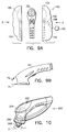
- Figure 5B shows the user grasping the apparatus 10 at the top of the head section 70 and cleaning tiles on a floor 100.
- the top of the head section 70 has been provided with a curved palm contact area 102 and a ridge 104 with an inwardly and downwardly sloping surface 106 below it.
- the ridge 104 is located at a perimeter of the top surface of the head section 70.
- a bottom portion 108 of the head section 70 has a general bell shaped outer perimeter.
- the bottom portion 108 has a centre axis that is angled relative to a centre axis of the handle section 68 at an angle D (see Figure 1) of about 95° to about 120°. In a preferred embodiment, the angle D is about 100°. However, any suitable angle could be provided.
- the surface 106 extends around a majority of the top surface of the head section.
- the curve of the top surface area 102 of the head section 70 has been configured to be matingly or comfortably received in a user's palm with the user's fingers wrapping around the ridge 104 and along the sloping surface 106.
- This shape provides for a grasping position as shown in Figure 5B where the user can locate his hand directly behind the cleaning attachment 20.
- This grasping position allows the user to exert additional force for the cleaning attachment 20 against the floor 100 with minimal additional effort, such as when using a relatively large diameter rotary scrub attachment or for heavy duty scrubbing.
- the attachment 110 generally comprises a frame 112 and a cleaning section 114.
- the frame 112 is comprised of a one-piece moulded plastic or polymer member.
- the frame 112 has a mounting section 116 for the mount 42 of the apparatus 10 and a cleaning pad attachment surface 118 on its bottom.
- the mounting section 116 is substantially the same as that shown in Figures 4D and 4E.
- the mounting section 116 has a generally triangular shaped aperture 90' into a receiving area 92' with three shelves 94' and three blocks 96'.
- the frame 112 could be comprised of multiple members fixedly connected to one another. Other types of mounting sections could be provided such that the attachment could be used with other types of cleaning apparatus.
- the bottom attachment surface 118 generally comprises a plurality of integrally formed hooks 120.
- the hooks 120 are resiliently deflectable such that the distal curved section 122 can be deflected to a partially straightened shape. Examples of similar hooks can be found in U.S. Patents 4,984,339 and 5,201,100.
- the cleaning section 114 in the embodiment shown, is a cleaning pad having a general disk or puck shape.
- the pad 114 is preferably comprised of intermeshed fibres; similar to a steel wool pad.
- the pad 114 is comprised of polymer fibres such as a SCOTCH-BRITE or BRUSHLON pad. SCOTCH-BRITE and BRUSHLON are trademarks of Minnesota Mining and Manufacturing Company of St. Paul Minnesota.
- a user In order to attach the pad 114 to the frame 112, a user merely places the pad 114 against the attachment surface 118 and applies pressure.
- the hooks 120 extend into the pad 114 and make a hooking attachment with the fibres of the pad 114. This completes assembly of the cleaning attachment 110.
- the pad 114 can be relatively easily removed from the frame 112 for replacement merely by pulling the pad 114 off of the hooks 120.
- the hooks 120 merely resiliently deflect to allow for disconnection of the pad 114.
- the connection of the pad to the frame is sufficiently to prevent the pad from coming off of the frame or significantly moving on the surface 118.
- additional or alternative means could be provided to attach the pad to the frame and, different types of cleaning sections could be provided.
- the cleaning attachment 130 generally comprises a housing 132, a rotating drive 134, and a cleaning section 136.
- the rotating drive 134 is suitably sized and shaped to receive the mount 42 of the apparatus 10. More specifically, the rotating drive 134, similar to that shown in Figures 4D and 4E, has a generally triangular shaped aperture, three shelves, three blocks, and a receiving area for the leading section of the mount 42.
- the rotating drive 134 is rotatably connected to the housing 132 and has a drive pin 138 extending from its bottom.
- the cleaning section 136 generally comprises a frame 140 and bristles 142 attached to the bottom side of the frame.
- the frame 140 is connected to the housing 132 to allow for sliding reciprocating linear movement, as shown by arrow E, relative to the housing 132.
- the frame 140 includes a laterally extending groove 144 (seen best in Figure 8C) on its top side.
- the drive pin 138 extends into the groove 144. When the drive 134 is rotated by the mount 42, the drive pin 138 is rotated as indicated by arrow C in Figure 8C.
- the drive pin 138 is able to laterally move in the groove 144, but otherwise causes the frame 140 to reciprocate back and forth on the housing 132 as indicated by arrow E.
- FIG. 8D shows another alternate embodiment.
- the rotating drive 134' is an elongate yoke with a centre of rotation F.
- the frame 140' of the cleaning section has a drive aperture 144' with the drive 134' therein.
- the frame 140' is moved in an orbital direction.
- the axial rotational movement of the drive 134' is converted into orbital motion of the cleaning attachment.
- the subassembly shell 22 shown in Figure 2A is shown being positioned into a mould 150 for overmoulding the cover 24 onto the shell.
- the mould 150 generally comprises two half mould members 152, 153 that have receiving areas 154, 155 therein.
- the moulding apparatus has a robotic arm that moves the shell 22 into and out of the mould 150.
- the robotic arm preferably has a stud that the shell 22 is mounted on.
- the shell 22 is mounted on the stud with the stud being located through the rear aperture 50 and into the battery receiving area 32. This stably supports the shell 22 for movement into and out of the mould 150.
- the members 26 of the shell 22 will be permanently connected to each other. Therefore, prior to insertion of the shell 22 into the mould 150, the two members 26 of the shell 22 are attached to each other by the screw 29 and rings 31 with the motor 18, transmission 58, switch 40, terminals 60, 61 and button cover 64 in place (see Figure 2).
- the two mould members 152, 153 are moved inward, as indicated by arrows G, to sandwich the shell 22 inside the receiving areas 154, 155.
- the raised areas 44, 46, 48 of the shell 22 are contacted by the mould members 152, 153 inside the receiving areas 154, 155. This contact provides two functions.
- the material of the cover is injection moulded at only two areas H 1 and H 2 at the front of the head section of the shell 22 at a relatively high pressure, such as about 3000 psi to about 5000 psi.
- the holding of the shell inside the mould at the raised areas 44, 46, 48 prevents the shell 22 from moving inside the mould 150 even with the relatively high injection pressure. Since the uniform gap between a majority of the shell outer surface and the walls of the mould inside the receiving areas 154, 155 is maintained during moulding, the cover 24 is moulded onto the shell 22 with a substantially uniform thickness over a majority of the shell 22.
- the hand guard 66 is simultaneously formed.
- the material of the shell 22 and the material of the cover 24 have similar melting points. Therefore, a melt bond occurs when the material of the cover 24 is injection moulded onto the shell 22. This prevents the cover 24 from being peeled off of the shell 22. However, due to the similar melting points, precautions had to be taken to prevent the injection moulding process from damaging the shell 22.
- the lower injection point H 1 is directly at the front metal ring 31 (see Figure 2).
- the upper injection point H 2 is parallel to the top surface of the shell, not directly at the shell 22. Thus, the shell is not significantly damaged by the hot injection material.
- the protection device 156 includes a slidable covering arm 158 and a mover 160.
- the arm 158 is slidingly mounted in a recess of the mould member 152 to project outward into the receiving area 154.
- the leading edge of the arm 158 is sized and shaped to cover and compress the button cover 64 against the shell 22 to prevent the injection moulded material from inwardly deforming the button cover 64 and damaging the switch 40.
- the mover 160 can be any suitable type of mover, such as a motor, a hydraulic drive or a pneumatic drive, to move the arm 158 between extended and retracted positions.
- the shell members 26 have structural strut sections 30 that form a honeycomb configuration. This is provided to support the outer walls of the shell 22 during the injection moulding process.
- the motor 18 and gear cage 56 form structural supports for the shell 22. This is also to support the outer walls of the shell 22 during the relatively high pressure of the injection moulding process.
- the motor 18 and the cage 56 also function as structural support members.
- the motor 18 and/or cage 56 could be attached to the shell 22 after the cover 24 is moulded over the shell 22.
- an insert should be used in place of the motor 18 and/or cage 56 during the overmoulding process.
- the purpose of the insert would be to structurally support the shell during the overmoulding process to prevent the shell from collapsing from the pressure during overmoulding.
- the stud of the robotic arm located in the battery receiving area 32 performs the same function at the handle section 68 to prevent collapse at the handle section during the overmoulding process.
- the mould 150 is opened and the shell with its new overmoulded cover is removed by the robotic arm.
- the cover 24 provides a waterproofing function.
- the cover 24 seals the majority of the joint between the two shell halves 26, seals the screw holes 28, and makes a seal with the button cover 64.
- the apparatus 10 can be used in wet locations without significant risk of being damaged by water, such as if the apparatus were accidentally dropped in a bucket of water during cleaning.
- the cover 24 also provides a relatively non-slippery surface over a majority of its surface. In wet environment uses this can be of great assistance to the user.
- the cover also provided a resilient deflectable surface over a majority of the apparatus 10 to resiliently absorb physical shocks, such as if the apparatus is accidentally dropped on a hard surface, such as a tile floor. This prevents damage to the apparatus and the surface it is dropped on.
- the thickness of the cover 24 on the shell 22 is not so thick as to take away from the attributes of the structurally rigid shell 22.
- Another advantage of the cover 24 is that it is moulded integral with the hand guard 66 for a clean and smooth surface that does not have seams that could otherwise collect dirt.
- the top surfaces of the raised areas 44, 46, 48 are also substantially even with the outer surface of the cover 24 to provide a uniform and stylish appearance.
- the cover 24 also provides the cam surface 80 at the shelf 78.
- the cover could be moulded onto a shell of any suitable type of motorised hand tool.
- Alternative shapes of the shell and raised areas on the shell could also be provided.
- the hand guard could also have any suitable type of shape or, need not be provided.
- an overmoulded cover need not be provided, such as by using gaskets between members or using rubber boots placed over members.
- the cleaning apparatus 200 is substantially the same as the apparatus 10 shown in Figure 1.
- the apparatus 200 includes a second cleaning attachment automatic disconnect button 202.
- the button 202 has a switch that is connected to the motor 204.
- the motor and transmission 206 rotate the mount 208 in direction C.
- the motor 204 rotates in a reverse direction. Therefore, the mount 208 is rotated in direction I which is reverse to direction C.
- the button 202 could actuate a lever to control the direction of the transmission 206 rather than change the rotation direction of the motor.
- any suitable type of automatic cleaning attachment disconnect system could be used to allow the user to disconnect a cleaning attachment without having to touch the cleaning attachment.
- a variable speed control for the motor could also be provided.
- a liquid dispenser could also be added.
- a swivel head could be provided or a head that is in-line with the handle.
- the apparatus is compact enough to clean inside a bathroom sink, but can also be used to extend the reach of the user.
- the cleaning apparatus 300 generally comprises a housing 302, a motor 304, batteries 306, a transmission 308, an actuating plate 310, a gasket 312, a cover 314 with studs, and five rotary shaped cleaning brushes 316.
- the housing 302 is made entirely of SANTOPRENE.
- the motor 304 rotates the drive gears of the transmission 308.
- the transmission rotates the five brushes 316.
- a bottom view of the apparatus 300 is shown at section J
- a schematic sectional view is shown at section K at the top of the brushes 316
- a schematic sectional view is shown at section L at the bottom of the actuating plate 310.
- the tops of the brushes 316 are rotatably mounted on studs 318 on the cover 314.
- Drive pins 320 from the gears of the transmission 308 extend into slots 322 in the tops of the brushes 316.
- the actuating plate 310 has slots 324.
- the drive pins 320 extend through the slots 324 from the gears 326 of the transmission.
- the gears 326 are rotated by the motor 304
- the drive pins 320 are rotated to reciprocatingly linearly move the actuating plate 310 from side to side as indicated by arrow M. This moves the cover 314 back and forth in direction M.
- the drive pins 320 also rotate the brushes 316 on their respective posts 318.
- the slots 322 provide clearance for off-centre movement of the cover 314 and brushes 316 relative to the rotational axes of the gears 326.
- Figure 11C shows another embodiment.
- the actuating plate 310' has curved slots 324'.
- the curved slots 324' provide orbital movement for the cover.
- Figure 11D shows a plan top view of an alternate embodiment of another type of actuating plate 310".
- the actuating plate 310" has two guide slots 330, 332. Each guide slot 330, 332 is located on an opposite side of the plate 310. Each guide slot 330, 332 is a linear slot and offset from each other 90°.
- a drive pin is located in the first guide slot 330, the rotational motion of the drive pin is converted in linear reciprocating movement of the plate 310" in direction M.
- the plate 310 similar to plate 310 of Figs.
- 11A and 11B has a cover with brushes connected to the plate 310".
- the brushes are moved in direction M.
- a user can remove the plate 310", flip it 180°, and reconnect the plate 310" with the drive pins now located in slots 332.
- the drive pins are rotated, the plate 310" is now reciprocatingly moved in direction N.
- Other types of motion or combinations of motions could also be provided, such as opposite side-by-side linear reciprocating sections and reverse direction rotating sections.
- FIG. 12 a partial cross-sectional view of an alternate embodiment is shown.
- the rear end of the ledge 78' of the shell 22' has an annular ring section 400, an annular recess 402, and the cover 24' has a reduced thickness at the recess 402.
- the battery cap 14' has an inner annular recess 404.
- the annular ring section 400 is received into the annular recess 404 to removably mechanically interlock the cap on the rear end of the housing.
- the inner surface 406 of the leading section 405 of the battery cap 14' makes a frictional and sealing engagement with the cover 24' at area 408.
- the leading section 405 is outwardly deformed in the mounted position shown in Figure 12. Thus, the leading section 405 compresses against the cover 24' at the area 408.
- other types of detent mounting systems could be provided.
- FIG 13 a partial top view of a cleaning attachment frame 86 similar to Figure 4D is shown with a cross-sectional view of the shaft 83' of an alternate embodiment in the aperture 90.
- the shaft 83' has a generally circular profile, but includes three detent sections 500.
- the detent sections 500 make an interference fit with side walls of the frame 86 in the aperture 90. This helps to prevent unintentional rotation of the frame 86 relative to the shaft 83'.
Abstract
A cleaning apparatus having a housing, a motor, a battery, and a removable cleaning attachment. The housing comprising a rigid subassembly shell and a resilient cover. The cover is injection moulded onto the shell to waterproof a majority of the shell. The shell has raised portions on its exterior that are used to position the shell in the injection mould. After moulding is completed, the cover surrounds the raised portions, but does not cover them.
Description
- The present invention relates to a housing for a tool and, more particularly, to a housing having a cover moulded onto a shell.
- The following U.S. Patents disclose various types of motorised cleaning tools with different housings:
U.S. Patent 4,168,560 U.S. Patent 4,158,246 U.S. Patent 2,849,736 U.S. Patent 3,289,231 U.S. Patent 3,396,417 U.S. Patent 3,417,417 U.S. Patent Des. 199,115 U.S. Patent Des. 200,293 U.S. Patent Des. 203,254 U.S. Patent Des. 219,790 U.S. Patent Des. 226,043 U.S. Patent Des. 226,941 U.S. Patent Des. 245,883 U.S. Patent Des. 245,948 U.S. Patent Des. 250,228 U.S. Patent Des. 257,747 U.S. Patent Des. 259,076 U.S. Patent Des. 262,257 U.S. Patent Des. 263,998 U.S. Patent Des. 281,035 U.S. Patent Des. 286,706 U.S. Patent Des. 290,550 U.S. Patent Des. 290,551 U.S. Patent Des. 300,185 U.S. Patent Des. 301,398 U.S. Patent Des. 305,480 U.S. Patent Des. 313,890 U.S. Patent Des. 321,596 U.S. Patent Des. 352,828 - The present invention provides a hand held cleaning apparatus characterised in that it comprises a rigid subassembly shell with a motor located therein, and a shell cover that is injection moulded around the shell after the motor has been located inside the shell.
- The present invention further provides a method of assembling a housing for a motorised appliance characterised in that it comprises the steps of connecting members of a shell to each other; and moulding a shell cover around the assembled shell to seal areas of connection between the members of the shell.
- The present invention further provides a hand held tool which comprises a motor, a battery and a housing, characterised in that the housing has a rigid multipiece subassembly shell and a shell cover moulded over the shell, the shell enclosing the motor and the cover comprising a resilient polymer material that is injection moulded onto a majority of an exterior surface of the shell, and provides a watertight seal over areas of connection between members that form the shell.
- The present invention further provides a method of assembling a housing for a motorised appliance characterised in that it comprises the steps of inserting a subassembly shell into a mould, the mould encapsulating the shell therein; moving a slide from within one portion of the mould to cover a deflectable member on the shell; and injecting a polymer material into the mould at a space between the shell and the mould to form a resilient cover over a majority of the shell.
- The present invention further provides a hand held cleaning apparatus characterised in that it comprises:
- a rigid subassembly shell with a motor therein; and
- a shell cover that is injection moulded around the shell before the motor has been located inside the shell.
- An embodiment of a hand held appliance according to the present invention will now be described with reference to the accompanying drawings, in which:
- Figure 1 is a perspective view of an embodiment of a battery operated cleaning apparatus incorporating features of the present invention;
- Figure 2 is a schematic cross sectional view of portions of the apparatus shown in Figure 1;
- Figure 2A is a perspective view of the apparatus shown in Figure 1 without the cover, battery cap, battery and cleaning attachment;
- Figure 3A is an enlarged elevational side view of the rear end of the apparatus shown in Figure 1;
- Figure 3B is an elevational side view as in Figure 3A with the battery cap axially rotated to a disconnection position;
- Figure 4A is a perspective view of the bottom of the attachment mount shown in Figure 2;
- Figure 4B is a perspective view of the top of the attachment mount shown in Figure 4A;
- Figure 4C is a cross sectional view of the mount shown in Figure 4B taken along
line 4C-4C; - Figure 4D is a plan top view of the mount aperture in the attachment shown in Figure 1;
- Figure 4E is a perspective view with a cut away section showing an interior mount receiving area inside the housing of the attachment;
- Figure 5A is a schematic perspective view of the apparatus shown in Figure 1 showing a user holding the apparatus at a first hand holding position;
- Figure 5B is a schematic perspective view of the apparatus shown in Figure 1 with a user holding the apparatus at a second hand holding position;
- Figure 6 is an exploded perspective view of an alternative embodiment of an attachment for use with the apparatus shown in Figure 1;
- Figure 7A is a cross sectional view of the housing shown in Figure 6;
- Figure 7B is an enlarged view of
section 7B shown in Figure 7A; - Figure 8A is a schematic perspective view of the apparatus shown in Figure 1 with an alternate embodiment of a cleaning attachment attached thereto;
- Figure 8B is a partial cross sectional view of the attachment shown in Figure 8A taken along
line 8B-8B; - Figure 8C is a cross sectional view of the apparatus shown in Figure 8B taken along
line 8C-8C; - Figure 8D is a schematic cross sectional view of an alternate embodiment of a cleaning attachment for use with the apparatus shown in Figure 8A;
- Figure 9A is a schematic view of the subassembly housing shown in Figure 2A being positioned into a mould;
- Figure 9B is an elevational side view of the subassembly housing shown in Figure 2A showing where material is injected at the subassembly housing inside the mould shown in Figure 9A;
- Figure 10 is a schematic perspective view of an alternate embodiment of the apparatus shown in Figure 1;
- Figure 11A is a schematic side elevational view of an alternate embodiment of the present invention;
- Figure 11B is a schematic partial bottom view and sectional views of the apparatus shown in Figure 11A;
- Figure 11C is a schematic partial bottom view and sectional views similar to Figure 11B of an alternate embodiment of the apparatus shown in Figure 11A;
- Figure 11D is a plan top view of a motion plate used in an alternate embodiment of the apparatus shown in Figure 11A;
- Figure 12 is a partial cross-sectional view of an alternate embodiment at a rear end of the tool; and
- Figure 13 is a partial top view of a frame of a clearing attachment and a cross-sectional view of an alternate embodiment of a mount.
- Referring to Figure 1, there is shown a perspective view of a battery operated cleaning
apparatus 10 incorporating features of the present invention. Although the present invention will be described with reference to the embodiments shown in the drawings, it should be understood that features of the present invention can be embodied in various alternative forms of embodiments. In addition, any suitable size, shape or type of elements or materials could be used. - Referring also to Figure 2, the
apparatus 10 generally comprises ahousing 12, abattery cap 14, abattery 16, amotor 18, and acleaning attachment 20. Referring also to Figure 2A, thehousing 12 generally comprises a subassembly housing orshell 22 and acover 24. Thesubassembly shell 22 comprises twohalf members 26; one of which is shown in Figure 2. The twomembers 26 are basically mirror images of each other and held together by asingle screw 29 at theholes 28 and metal rings 31 at the front and rear of themembers 26. In an alternate embodiment, only onering 31 is needed at the front of theshell 31. In another alternate embodiment, there might be no metal rings used. The interiors of themembers 26 have a honeycomb configuration provided bystructural strut sections 30. Themembers 26 also have fourareas battery 16, themotor 18, aswitch 40, and anattachment mount 42, respectively. - The exterior of each
member 26 has raisedareas members 26 are assembled, as shown in Figure 2, only three apertures are provided into thesubassembly shell 22; the aperture in which theswitch 40 is located, a rearbattery entrance aperture 50 and a front aperture in which themount 42 is located. Thecover 24 is injection moulded over thesubassembly shell 22 as further described below. Thecover 24 is preferably comprised of SANTOPRENE. SANTOPRENE is a trademark of Advanced Elastomer Systems of Akron, Ohio. The cover 24 (see Figure 1) forms an outer skin over a majority of thesubassembly shell 22. Thecover 24 also forms ahand guard section 66. Thehand guard section 66 extends along the bottom of theapparatus 10 between the rear end of thehandle section 68 and the bottom of thefront head section 70. This forms a loop. A user's fingers can extend into that loop. - Referring primarily to Figure 2, the
motor 18 is preferably a brushless DC motor with anoutput shaft 52 andelectrical terminals 54. Themotor 18 is located in a motor/gear support cage 56 before being placed between the twomembers 26. Also located in thecage 56 aregears 58 that form a transmission between thedrive shaft 52 and themount 42. In a preferred embodiment, thegears 58 form a planetary gear transmission to convert the high speed low tongue output of the motor into a slower speed higher tongue output for the tool. The advantages of this approach are robustness of a planetary gear system and over all smaller space requirements. The planetary gear approach is robust because it is forgiving in the sense that the unit doesn't require the tight manufacturing tolerances and the system has no side loads applied to the gears. The planetary gear approach is a physically smaller approach for this particular design approach in the regard that a tremendous reduction gear ratio is achievable without having a large space requirement with respect to distance for the motor centreline. However, in alternate embodiments, other gearing approaches could be used, such as spur gears, bevel gears, helical gears or worm gears. Themotor 18 andcage 56 are received in the receivingaperture 34 such that it forms a structural support between the twomembers 26. This structural support cooperates with the structure of themembers 26 for the purpose of withstanding compression during overmoulding of thecover 24. Theterminals 54 of the motor are connected by wires to theswitch 40 and twospring contact terminals terminals battery receiving area 32. Thebattery receiving area 32 has a general tubular shape. Thebattery 16 has a general column shape with two coaxial terminals 62, 63. Thefirst terminal 60 is located to make contact with the centre terminal 62 of thebattery 16. Thesecond terminal 61 is located to make contact with the outer terminal 63 of thebattery 16. The two battery terminals are generally coaxially located relative to each other at a single end of thebattery 16. Thebattery 16 is preferably a rechargeable battery such as a VERSAPAK battery sold by Black & Decker (U.S.) Inc. VERSAPAK is a trademark of The Black & Decker Corporation of Towson, Maryland. However, any suitable type of battery could be used. In alternate embodiments, the apparatus could be modified to accept any suitable type of battery or batteries. In the embodiment shown, when thebattery 16 is fully inserted into thebattery receiving area 32, therear end 76 of the battery extends out of theaperture 50 past the rear end of the housing. The twospring contact terminals battery 16. The terminal 61 does not extend into the annular groove 65 along the outer battery terminal. Therefore, the terminal 61 does not make a snap-lock retainment with the annular groove 65. In a preferred embodiment, the frictional forces between thespring contact terminals battery 16 inside thebattery receiving area 32, even when thebattery cap 14 is not connected to thehousing 12, until intentionally removed by a user. However, in an alternate embodiment, this frictional engagement could be insufficient to mechanically retain the weight of the battery when the battery is vertically located below thespring contact terminals - The
first terminal 60 is connected by a wire directly to one of theterminals 54 of themotor 18. Thesecond terminal 61 is connected by a wire to theswitch 40 which, in turn, is connected by a wire to one of theterminals 54 of themotor 18. Theswitch 40 is preferably a push-button ON/OFF switch. However, in alternate embodiments, any suitable type of switch could be used. The base of theswitch 40 is stationarily positioned in the receivingarea 36. Covering theswitch 40 is abutton cover 64. Thebutton cover 64 is comprised of a flexible polymer material such that it can be deflected by a user's finger to actuate theswitch 40. - Referring also to Figure 3A, an enlarged view of the rear end of the
apparatus 10 is shown. Thebattery cap 14 is preferably made of a polymer material. Thebattery cap 14 has afront edge 72 with a wavy shape having peaks and valleys. Thebattery cap 14 also has a receivingarea 74 for receiving the rear end 76 (see Figure 2) of thebattery 16. The rear end of thehousing 12 has a ledge 78 (see Figure 2). Thecover 24 does not extend onto theledge 78. Theledge 78 has a general ring shape at the entrance of the battery receiving area. Therear edge 80 of thecover 24 has a wavy shape with peaks and valleys that is complimentary to thefront edge 72 of thebattery cap 14. Therear edge 80 is located next to theledge 78 and outward relative to the ledge. Thebattery cap 14 is friction mounted on theledge 78 of thesubassembly shell 22. Theledge 78 has a smooth outer surface such that only frictional grasping of thebattery cap 14 on the ledge retains the battery cap to the ledge. To mount thebattery cap 14 to theledge 78, a user merely slides the cap onto the ledge by pushing the cap andhousing 12 together. As seen in Figure 3A, when thebattery cap 14 is properly connected to thehousing 12, the twoedges battery cap 14 to theledge 78 is relatively strong and forms a watertight seal. To allow relatively easy removal of thebattery cap 14, the user can use theedges battery cap 14 on theledge 78 as indicated by arrow A. This causes the slopes leading up to the peaks to coact against each other to move thebattery cap 14 in direction B. Thus, axial rotation of the battery cap relative to the housing causes the battery cap to be cammed away from the housing by the cam surfaces. As seen best in Figure 3A, thebattery cap 14 has abottom section 75 that extends downward off centre from the centreline of the mounting of the battery cap on the ledge. This offcentre section 75 has been provided to give a user better leverage in axially rotating thecap 14 on theledge 78. The camming action between thecap 14 and thecover 24 need not completely push thecap 14 off theledge 78, but preferably moves the cap 14 a majority of the length of theledge 78. In alternate embodiments other types of battery cap removal assistance could be provided. - The
battery cap 14 is provided to close off theaperture 50 and form a watertight seal with theledge 78. In addition, thebattery cap 14 functions as a retainer to keep thebattery 16 attached to theterminals battery 16 to retain the battery. This has been purposely done to encourage users to only use theapparatus 10 with thebattery cap 14 in place. As noted above, in one embodiment the frictional engagement between the terminals of the battery and the apparatus is insufficient to mechanically retain the weight of the battery when the battery is vertically oriented beneath theterminals battery 16 from automatically sliding out of the housing, the user merely needs to slide thebattery cap 14 onto theledge 78. If a user tries to use the apparatus without thebattery cap 14, and tilts the rear end of the housing down, thebattery 16 will slide out of the housing under its own weight. This design allows an easy attachment and removal of the battery cap using an intuitive rotating motion and requires no secondary sealing gasket for the battery cap. Alternative designs could include a bayonet design or a snap-lid with a thumbnail lip. - Referring now to Figures 2, 4A, 4B and 4C the
attachment mount 42 generally comprises a one-piece polymer member that is attached to an output shaft from thetransmission 58. Themount 42 includes a stud with ashaft receiving area 82 and a leadingsection 84 that has a general triangular block shape. Themount 42 also has a relatively narrow neck orshaft section 83 behind the leadingsection 84. This formsslots 85 behind cantilevered generally triangular shapedtips 81 of the leadingsection 84. Referring also to Figures 4D and 4E, portions of thecleaning attachment 20 are shown. Theattachment 20 generally comprises aframe 86 and bristles 88 (see Figure 1). - The
bristles 88 are connected to the bottom of theframe 86 and extend therefrom. Figure 4D shows a partial top plan view of the centre of theframe 86. Theframe 86 has a centre generally triangular shapedaperture 90. Theaperture 90 is about the same size and shape as the leadingsection 84 of themount 42 such that the leadingsection 84 can pass therethrough. Figure 4E is a partial perspective cutaway view of theframe 86 at theaperture 90. Located behind theaperture 90 is a receivingarea 92. The receivingarea 92 has three retainingshelves 94 and three stop blocks 96. - To attach the
frame 86 to themount 42, themount section 84 is merely inserted through theaperture 90 into the receivingarea 92. Theframe 86 and mount 42 are then rotated relative to each other such that thetriangular tips 81 of the leadingsection 84 move behind theshelves 94. Theshelves 94 are received in theslots 85 of themount 42. The stop blocks 96 stop the relative rotation of themount 42 by contacting thetriangular tips 81. This interlocking of themount 42 andframe 86 keeps theattachment 20 connected to themount 42. In the embodiment shown, themotor 18 andtransmission 58 are only capable of rotating themount 42 in one direction C shown in Figures 1 and 4E. In order to disconnect or remove theattachment 20, a user merely rotates theattachment 20 by hand in a direction reverse to direction C until the leadingsection 84 aligns with theaperture 90. Then, theattachment 20 can be separated from themount 42. The areas of contact between theshelves 94 and the rear sides of thetips 81 is sufficiently large to provide sufficient frictional force to inhibit unintentional relative rotation between themount 42 and the frame in a direction reverse to direction C without any additional biasing or holding between the two. Thus, because only friction is being used to prevent relative rotation in a direction reverse to direction C, a user only needs to use minimal force to rotate thecleaning attachment 20 in a disconnection direction. Therefore, the user does not need to grab a large area of the cleaning attachment, which might otherwise be very dirty from use. This minimises the user's hands getting dirty or coming into contact with caustic cleaning material. In an alternate embodiment a short spiral mounting system could be provided. Other alternatives could include a one or two blade bayonet design. However, the three blade or trilobular bayonet design of themount 42 is preferred because it is a simple attachment and removable by executing about a 1/6 turn. A counterclockwise engaging system could also be used rather than a clockwise engaging system. Another alternate embodiment could include the cleaning attachment having the mount and the apparatus having the receiving area. - Referring now to Figures 5A and 5B, the
apparatus 10 is shown with a user grasping theapparatus 10 at two different locations. More specifically, thehousing 12 has been designed to provide two primary hand holding positions. "Primary hand holding position" is intended to mean a position in which a users' hand can comfortably and surely hold the apparatus during use; i.e.: a location specifically and intentionally designed for the user to hold the apparatus during use. The two primary hand holding positions allow a user to properly hold theapparatus 10 based upon the type of attachment being used and/or the type of cleaning task. The shape of the housing also allows for easy articulation around items, such as bathroom fixtures. Figure 5A shows a user grasping theapparatus 10 at thehandle section 68 and cleaning tiles on awall 98. Thehandle section 68 has a general tubular shape, with thebattery 16 therein, for this purpose. Thehandle section 68 extends rigidly from a top rear portion of the head section. This holding position allows the user to scrub areas at a distance, such as above the user's head. Thebutton cover 64 and switch 40 (see Figure 2) are suitably located to be depressed by the user's index finger in this holding position. Thehand guard section 66 protects the user's knuckles from hitting thewall 98. Figure 5B, on the other hand, shows the user grasping theapparatus 10 at the top of thehead section 70 and cleaning tiles on afloor 100. As seen in Figure 1, the top of thehead section 70 has been provided with a curvedpalm contact area 102 and aridge 104 with an inwardly and downwardly slopingsurface 106 below it. Theridge 104 is located at a perimeter of the top surface of thehead section 70. Abottom portion 108 of thehead section 70 has a general bell shaped outer perimeter. Thebottom portion 108 has a centre axis that is angled relative to a centre axis of thehandle section 68 at an angle D (see Figure 1) of about 95° to about 120°. In a preferred embodiment, the angle D is about 100°. However, any suitable angle could be provided. Thesurface 106 extends around a majority of the top surface of the head section. The curve of thetop surface area 102 of thehead section 70 has been configured to be matingly or comfortably received in a user's palm with the user's fingers wrapping around theridge 104 and along thesloping surface 106. This shape provides for a grasping position as shown in Figure 5B where the user can locate his hand directly behind thecleaning attachment 20. This grasping position allows the user to exert additional force for thecleaning attachment 20 against thefloor 100 with minimal additional effort, such as when using a relatively large diameter rotary scrub attachment or for heavy duty scrubbing. - Referring now to Figure 6, an exploded schematic perspective view of an alternate embodiment of a cleaning attachment for use with the
apparatus 10 is shown. Theattachment 110 generally comprises aframe 112 and acleaning section 114. Referring also to Figures 7A and 7B, theframe 112 is comprised of a one-piece moulded plastic or polymer member. Theframe 112 has a mountingsection 116 for themount 42 of theapparatus 10 and a cleaningpad attachment surface 118 on its bottom. The mountingsection 116 is substantially the same as that shown in Figures 4D and 4E. The mountingsection 116 has a generally triangular shaped aperture 90' into a receiving area 92' with three shelves 94' and three blocks 96'. In an alternate embodiment, theframe 112 could be comprised of multiple members fixedly connected to one another. Other types of mounting sections could be provided such that the attachment could be used with other types of cleaning apparatus. Thebottom attachment surface 118 generally comprises a plurality of integrally formed hooks 120. Thehooks 120 are resiliently deflectable such that the distalcurved section 122 can be deflected to a partially straightened shape. Examples of similar hooks can be found in U.S. Patents 4,984,339 and 5,201,100. Thecleaning section 114, in the embodiment shown, is a cleaning pad having a general disk or puck shape. Thepad 114 is preferably comprised of intermeshed fibres; similar to a steel wool pad. Preferably, thepad 114 is comprised of polymer fibres such as a SCOTCH-BRITE or BRUSHLON pad. SCOTCH-BRITE and BRUSHLON are trademarks of Minnesota Mining and Manufacturing Company of St. Paul Minnesota. - In order to attach the
pad 114 to theframe 112, a user merely places thepad 114 against theattachment surface 118 and applies pressure. Thehooks 120 extend into thepad 114 and make a hooking attachment with the fibres of thepad 114. This completes assembly of thecleaning attachment 110. Thepad 114 can be relatively easily removed from theframe 112 for replacement merely by pulling thepad 114 off of thehooks 120. Thehooks 120 merely resiliently deflect to allow for disconnection of thepad 114. However, during normal use ofattachment 110, the connection of the pad to the frame is sufficiently to prevent the pad from coming off of the frame or significantly moving on thesurface 118. In alternate embodiments, additional or alternative means could be provided to attach the pad to the frame and, different types of cleaning sections could be provided. - Referring now to Figure 8A, another alternate embodiment of a cleaning attachment is shown connected to the
apparatus 10. Thecleaning attachment 130 generally comprises ahousing 132, arotating drive 134, and acleaning section 136. Referring also to Figures 8B and 8C, therotating drive 134 is suitably sized and shaped to receive themount 42 of theapparatus 10. More specifically, therotating drive 134, similar to that shown in Figures 4D and 4E, has a generally triangular shaped aperture, three shelves, three blocks, and a receiving area for the leading section of themount 42. Therotating drive 134 is rotatably connected to thehousing 132 and has adrive pin 138 extending from its bottom. Thecleaning section 136 generally comprises aframe 140 and bristles 142 attached to the bottom side of the frame. Theframe 140 is connected to thehousing 132 to allow for sliding reciprocating linear movement, as shown by arrow E, relative to thehousing 132. Theframe 140 includes a laterally extending groove 144 (seen best in Figure 8C) on its top side. Thedrive pin 138 extends into thegroove 144. When thedrive 134 is rotated by themount 42, thedrive pin 138 is rotated as indicated by arrow C in Figure 8C. Thedrive pin 138 is able to laterally move in thegroove 144, but otherwise causes theframe 140 to reciprocate back and forth on thehousing 132 as indicated by arrow E. Thus, the axial rotational driving motion of themount 42 is transformed into linear reciprocating motion. In alternate embodiments, other types of mechanical connections could be provided among the members of the cleaning attachment and any suitable type of cleaning section could be provided. Figure 8D shows another alternate embodiment. In this embodiment the rotating drive 134' is an elongate yoke with a centre of rotation F. The frame 140' of the cleaning section has a drive aperture 144' with the drive 134' therein. As the drive 134' is rotated, the frame 140' is moved in an orbital direction. Thus, the axial rotational movement of the drive 134' is converted into orbital motion of the cleaning attachment. - Referring now to Figure 9A, the
subassembly shell 22 shown in Figure 2A is shown being positioned into amould 150 for overmoulding thecover 24 onto the shell. Themould 150 generally comprises twohalf mould members areas shell 22 into and out of themould 150. The robotic arm preferably has a stud that theshell 22 is mounted on. Referring also to Figure 2A, theshell 22 is mounted on the stud with the stud being located through therear aperture 50 and into thebattery receiving area 32. This stably supports theshell 22 for movement into and out of themould 150. - Once the
cover 24 is overmoulded onto theshell 22, themembers 26 of theshell 22 will be permanently connected to each other. Therefore, prior to insertion of theshell 22 into themould 150, the twomembers 26 of theshell 22 are attached to each other by thescrew 29 and rings 31 with themotor 18,transmission 58,switch 40,terminals shell 22 is moved into themould 150, the twomould members shell 22 inside the receivingareas areas shell 22 are contacted by themould members areas areas cover 24 is injected into themould 150, the material is not moulded over the top surfaces of the raisedareas areas mould 150 stationarily holds the shell inside the receivingareas areas shell 22. There are a few exceptions to this uniform gap; namely, at the area proximate the soon to be formedhand guard 66 and, at therear ledge 78 and bottom of thehead section 70 that are covered to prevent moulding of the cover material over these areas. As shown in Figure 9B, the material of the cover is injection moulded at only two areas H1 and H2 at the front of the head section of theshell 22 at a relatively high pressure, such as about 3000 psi to about 5000 psi. The holding of the shell inside the mould at the raisedareas shell 22 from moving inside themould 150 even with the relatively high injection pressure. Since the uniform gap between a majority of the shell outer surface and the walls of the mould inside the receivingareas cover 24 is moulded onto theshell 22 with a substantially uniform thickness over a majority of theshell 22. Thehand guard 66 is simultaneously formed. - In a preferred embodiment, the material of the
shell 22 and the material of thecover 24 have similar melting points. Therefore, a melt bond occurs when the material of thecover 24 is injection moulded onto theshell 22. This prevents thecover 24 from being peeled off of theshell 22. However, due to the similar melting points, precautions had to be taken to prevent the injection moulding process from damaging theshell 22. In particular, the lower injection point H1, is directly at the front metal ring 31 (see Figure 2). The upper injection point H2 is parallel to the top surface of the shell, not directly at theshell 22. Thus, the shell is not significantly damaged by the hot injection material. - Due to the relatively high injection pressure being used, in order to prevent damage to the
switch 40, and to prevent the button cover 64 from being permanently inwardly deformed, or perhaps even dislodged, one of themould members 152 has been provided with aprotection device 156. Theprotection device 156 includes aslidable covering arm 158 and amover 160. Thearm 158 is slidingly mounted in a recess of themould member 152 to project outward into the receivingarea 154. The leading edge of thearm 158 is sized and shaped to cover and compress thebutton cover 64 against theshell 22 to prevent the injection moulded material from inwardly deforming thebutton cover 64 and damaging theswitch 40. However, thearm 158 does allow thecover 24 to be injected around the side perimeter of thebutton cover 64 and form a watertight seal therewith. Themover 160 can be any suitable type of mover, such as a motor, a hydraulic drive or a pneumatic drive, to move thearm 158 between extended and retracted positions. As noted above, theshell members 26 havestructural strut sections 30 that form a honeycomb configuration. This is provided to support the outer walls of theshell 22 during the injection moulding process. Also, as noted above, themotor 18 andgear cage 56 form structural supports for theshell 22. This is also to support the outer walls of theshell 22 during the relatively high pressure of the injection moulding process. Thus, themotor 18 and thecage 56 also function as structural support members. - In an alternate embodiment, the
motor 18 and/orcage 56 could be attached to theshell 22 after thecover 24 is moulded over theshell 22. However, in such an alternate embodiment an insert should be used in place of themotor 18 and/orcage 56 during the overmoulding process. The purpose of the insert would be to structurally support the shell during the overmoulding process to prevent the shell from collapsing from the pressure during overmoulding. The stud of the robotic arm (not shown) located in thebattery receiving area 32 performs the same function at thehandle section 68 to prevent collapse at the handle section during the overmoulding process. - Once the moulding process is complete, the
mould 150 is opened and the shell with its new overmoulded cover is removed by the robotic arm. There are many purposes to overmoulding thecover 24 onto theshell 22. Thecover 24 provides a waterproofing function. Thecover 24 seals the majority of the joint between the twoshell halves 26, seals the screw holes 28, and makes a seal with thebutton cover 64. With a seal at themount 42 and the seal by thebattery cap 14, theapparatus 10 can be used in wet locations without significant risk of being damaged by water, such as if the apparatus were accidentally dropped in a bucket of water during cleaning. Thecover 24 also provides a relatively non-slippery surface over a majority of its surface. In wet environment uses this can be of great assistance to the user. The cover also provided a resilient deflectable surface over a majority of theapparatus 10 to resiliently absorb physical shocks, such as if the apparatus is accidentally dropped on a hard surface, such as a tile floor. This prevents damage to the apparatus and the surface it is dropped on. However, the thickness of thecover 24 on theshell 22 is not so thick as to take away from the attributes of the structurallyrigid shell 22. Another advantage of thecover 24 is that it is moulded integral with thehand guard 66 for a clean and smooth surface that does not have seams that could otherwise collect dirt. The top surfaces of the raisedareas cover 24 to provide a uniform and stylish appearance. Thecover 24 also provides thecam surface 80 at theshelf 78. In alternate embodiments, the cover could be moulded onto a shell of any suitable type of motorised hand tool. Alternative shapes of the shell and raised areas on the shell could also be provided. The hand guard could also have any suitable type of shape or, need not be provided. In alternate embodiments, an overmoulded cover need not be provided, such as by using gaskets between members or using rubber boots placed over members. - Referring now to Figure 10, a schematic perspective view of an alternate embodiment of the cleaning apparatus is shown. The
cleaning apparatus 200 is substantially the same as theapparatus 10 shown in Figure 1. However, in this embodiment, theapparatus 200 includes a second cleaning attachmentautomatic disconnect button 202. Thebutton 202 has a switch that is connected to themotor 204. During normal use of theapparatus 200 the motor andtransmission 206 rotate themount 208 in direction C. However, when a user actuates thebutton 202, themotor 204 rotates in a reverse direction. Therefore, themount 208 is rotated in direction I which is reverse to direction C. Due to the fact that only frictional forces keep the frame of the cleaning attachment from rotating relative to themount 208 in direction I, when themount 208 is rotated in direction I the shelves of the attachment slip on themount 208 such that themount 208 aligns with the triangular aperture 90 (see Figure 4E) of the attachment frame. The cleaning attachment can then merely fall off of themount 208. Therefore, a user does not need to touch the cleaning attachment to remove it from theapparatus 200. In an alternate embodiment, thebutton 202 could actuate a lever to control the direction of thetransmission 206 rather than change the rotation direction of the motor. Alternatively, any suitable type of automatic cleaning attachment disconnect system could be used to allow the user to disconnect a cleaning attachment without having to touch the cleaning attachment. A variable speed control for the motor could also be provided. A liquid dispenser could also be added. In another alternate embodiment a swivel head could be provided or a head that is in-line with the handle. Preferably, the apparatus is compact enough to clean inside a bathroom sink, but can also be used to extend the reach of the user. - Referring now to Figure 11A, an alternate embodiment of a cleaning apparatus is shown. The
cleaning apparatus 300 generally comprises ahousing 302, amotor 304,batteries 306, atransmission 308, anactuating plate 310, agasket 312, acover 314 with studs, and five rotary shaped cleaning brushes 316. In this embodiment thehousing 302 is made entirely of SANTOPRENE. Themotor 304 rotates the drive gears of thetransmission 308. The transmission rotates the five brushes 316. Referring also to Figure 11B, a bottom view of theapparatus 300 is shown at section J, a schematic sectional view is shown at section K at the top of thebrushes 316, and a schematic sectional view is shown at section L at the bottom of theactuating plate 310. The tops of thebrushes 316 are rotatably mounted onstuds 318 on thecover 314. Drive pins 320 from the gears of thetransmission 308 extend intoslots 322 in the tops of thebrushes 316. Theactuating plate 310 hasslots 324. The drive pins 320 extend through theslots 324 from thegears 326 of the transmission. As thegears 326 are rotated by themotor 304, the drive pins 320 are rotated to reciprocatingly linearly move theactuating plate 310 from side to side as indicated by arrow M. This moves thecover 314 back and forth in direction M. The drive pins 320 also rotate thebrushes 316 on theirrespective posts 318. Theslots 322 provide clearance for off-centre movement of thecover 314 and brushes 316 relative to the rotational axes of thegears 326. - Figure 11C shows another embodiment. In this embodiment the actuating plate 310' has curved slots 324'. The curved slots 324' provide orbital movement for the cover. Figure 11D shows a plan top view of an alternate embodiment of another type of
actuating plate 310". Theactuating plate 310" has twoguide slots guide slot plate 310. Eachguide slot first guide slot 330, the rotational motion of the drive pin is converted in linear reciprocating movement of theplate 310" in direction M. Theplate 310", similar toplate 310 of Figs. 11A and 11B has a cover with brushes connected to theplate 310". Thus, the brushes are moved in direction M. However, a user can remove theplate 310", flip it 180°, and reconnect theplate 310" with the drive pins now located inslots 332. When the drive pins are rotated, theplate 310" is now reciprocatingly moved in direction N. Thus, the user can select from two alternative types of motion of the brushes. Other types of motion or combinations of motions could also be provided, such as opposite side-by-side linear reciprocating sections and reverse direction rotating sections. - Referring now to Figure 12, a partial cross-sectional view of an alternate embodiment is shown. In this embodiment the rear end of the ledge 78' of the shell 22' has an
annular ring section 400, anannular recess 402, and the cover 24' has a reduced thickness at therecess 402. The battery cap 14' has an innerannular recess 404. When the cap 14' is mounted to the ledge 78', theannular ring section 400 is received into theannular recess 404 to removably mechanically interlock the cap on the rear end of the housing. Theinner surface 406 of the leadingsection 405 of the battery cap 14' makes a frictional and sealing engagement with the cover 24' atarea 408. The leadingsection 405 is outwardly deformed in the mounted position shown in Figure 12. Thus, the leadingsection 405 compresses against the cover 24' at thearea 408. In alternate embodiments, other types of detent mounting systems could be provided. - Referring now to Figure 13, a partial top view of a
cleaning attachment frame 86 similar to Figure 4D is shown with a cross-sectional view of the shaft 83' of an alternate embodiment in theaperture 90. The shaft 83' has a generally circular profile, but includes threedetent sections 500. Thedetent sections 500 make an interference fit with side walls of theframe 86 in theaperture 90. This helps to prevent unintentional rotation of theframe 86 relative to the shaft 83'.
Claims (35)
- A hand held cleaning apparatus characterised in that it comprises:a rigid subassembly shell (22) with a motor (18) therein; anda shell cover (24) that is injection moulded around the shell (22) after the motor (18) has been located inside the shell (22).
- An apparatus as in Claim 1 characterised in that the shell (22) comprises two half members (26) which are generally mirror images of each other and which are connected to each other by a screw (29).
- An apparatus as in Claim 1 or Claim 2 characterised in that the cover (24) is composed of a resilient polymer material.
- An apparatus as in any of Claims 1 to 3 characterised in that the cover (24) forms a hand guard section (66) for the apparatus.
- An apparatus as in Claim 4 characterised in that the cover (24) has a substantially uniform thickness on the shell (22) except at the hand guard section (66).
- An apparatus as in any of Claims 1 to 5 characterised in that the shell (22) includes raised areas (44,46,48) on its exterior that are surrounded by the cover (24), but are not covered by the cover (24).
- An apparatus as in Claim 6 characterised in that the raised areas (44,46,48) have top surfaces that are substantially even with the cover (24).
- An apparatus as in Claim 1 characterised in that it further comprises a battery cap (14) that is frictionally mounted on the shell (22) to seal off a battery receiving area (32) inside the shell (22).
- An apparatus as in Claim 1 characterised in that the shell cover (24) surrounds a flexible button cover (64) on the shell (22), but does not completely cover the button cover (64), the shell cover (24) forming a watertight seal with the button cover (64).
- An apparatus as in Claim 1 characterised in that the shell cover (24) forms a watertight seal around substantially the entire shell (22).
- A method of assembling a housing for a motorised appliance characterised in that it comprises the steps of:connecting members (26) of a shell (22) to each other; andmoulding a shell cover (24) around the assembled shell (22) to seal areas of connection between the members of the shell.
- A method as in Claim 11 characterised in that the step of connecting the members of the shell (22) comprises attaching two half members (26) which are generally mirror images of each other to each other with a single screw (29).
- A method as in Claim 11 characterised in that the step of connecting the members of the shell (22) comprises attaching two half members (26) which are generally mirror images of each other to each other with at least one metal retaining ring (31), the ring surrounding the shell at a front end drive aperture (38).
- A method as in Claim 11 characterised in that the step of moulding comprises placing the shell (22) into a mould (150) and injection moulding the cover (24) over a majority of the shell (22).
- A method as in Claim 14 characterised in that the step of moulding includes holding the shell (22) stationary in the mould (150) and providing a substantially uniform space between a majority of the shell (22) and the mould (150) such that the cover (24) has a substantially uniform thickness on a majority of the shell (22).
- A method as in Claim 14 characterised in that the shell (22) has raised areas (44,46,48) on its exterior that are contacted by the mould (150) to hold the shell (22) in a stationary position in the mould (150) during injection moulding.
- A method as in Claim 16 characterised in that the step of moulding moulds the cover (24) around the raised areas (44, 46 48), but does not cover the raised areas with the cover.
- A method as in Claim 11 characterised in that the step of moulding a cover (24) also moulds a hand guard section (66) that forms a loop.
- A method as in Claim 11 characterised in that it further comprises moving a portion of the mould (150) to cover a button cover (64) connected to the shell (22) such that the shell cover (24) is moulded around the button cover (64) and forms a watertight seal therewith.
- A hand held tool has a motor (18), a battery (16) and a housing (12) characterised in that:
the housing (12) has a rigid multi-piece subassembly shell (22) and a shell cover (24) moulded over the shell, the shell (22) enclosing the motor (18), and the cover comprising a resilient polymer material that is injection moulded onto a majority of an exterior surface of the shell (22) and provides a watertight seal over areas of connection between members that form the shell (22). - A tool as.in Claim 20 characterised in that the shell (22) comprises two half members (26) which are generally mirror images of each other and which are connected to each other around the motor (18) and form a battery receiving area (32), and the cover seals substantially an entire joint between the two members (26).
- A tool as in Claim 20 characterised in that the cover (24) forms a hand guard section (66) for the tool.
- A tool as in Claim 22 characterised in that the cover (24) has a uniform thickness on the shell (22) except at the hand guard section (66).
- A tool as in Claim 20 characterised in that the shell (22) includes raised areas (44,46,48) on its exterior that are surrounded by the cover (24), but are not covered by the cover (24).
- A tool as in Claim 24 characterised in that the raised areas (44,46,48) have top surfaces that are substantially even with the cover (24).
- A tool as in Claim 20 characterised in that the cover (24) has a substantially uniform thickness on a majority of the shell (22).
- A tool as in Claim 20 characterised in that the shell cover (24) surrounds a flexible button cover (64) on the shell (22), but does not completely cover the button cover (64), the shell cover (24) forming a watertight seal with the button cover (64).
- A tool as in Claim 20 characterised in that the shell cover (24) forms a watertight seal around substantially the entire shell (22).
- A method of assembling a housing (12) for a motorised appliance characterised in that it comprises the steps of:inserting a subassembly shell (22) into a mould (150), the mould (15) encapsulating the shell (22) therein;moving a slide from within one portion of the mould to cover a deflectable member on the shell; andinjecting a polymer material into the mould (150) at a space between the shell (22) and the mould to form a resilient cover (24) over a majority of the shell (22).
- A method as in Claim 29 characterised in that it further comprises the step of attaching two half members (26) which are generally mirror images of each other to each other to form the shell (22).
- A method as in Claim 29 characterised in that the step of inserting includes holding the shell (22) stationary in the mould (150) and providing a substantially uniform space between a majority of the shell (22) and the mould (150) such that the cover (24) has a substantially uniform thickness on a majority of the shell (22).
- A method as in Claim 29 characterised in that the shell (22) has raised areas (44,46,48) on its exterior that are contacted by the mould (150) to hold the shell (22) in a stationary position in the mould (150) during the step of injecting.
- A method as in Claim 32 characterised in that the step of injecting moulds the cover (24) around the raised areas (44,46,48), but does not cover the raised areas (44,46,48) with the cover (24).
- A method as in Claim 29 characterised in that the step of injecting also moulds a hand guard section (66) that forms a loop.
- A hand held cleaning apparatus characterised in that it comprises:a rigid subassembly shell (22) with a motor (18) therein; anda shell cover (24) that is injection moulded around the shell (22) before the motor (18) has been located inside the shell (22).
Applications Claiming Priority (2)
| Application Number | Priority Date | Filing Date | Title |
|---|---|---|---|
| US639149 | 1991-01-09 | ||
| US08/639,149 US5718014A (en) | 1996-04-29 | 1996-04-29 | Hand held motorized tool with over-molded cover |
Publications (1)
| Publication Number | Publication Date |
|---|---|
| EP0804985A1 true EP0804985A1 (en) | 1997-11-05 |
Family
ID=24562933
Family Applications (1)
| Application Number | Title | Priority Date | Filing Date |
|---|---|---|---|
| EP97302900A Ceased EP0804985A1 (en) | 1996-04-29 | 1997-04-28 | Hand held motorised tool with over-moulded cover |
Country Status (7)
| Country | Link |
|---|---|
| US (2) | US5718014A (en) |
| EP (1) | EP0804985A1 (en) |
| JP (1) | JPH1043106A (en) |
| CN (1) | CN1137648C (en) |
| AU (1) | AU725412B2 (en) |
| BR (1) | BR9700627A (en) |
| CA (1) | CA2203347A1 (en) |
Cited By (14)
| Publication number | Priority date | Publication date | Assignee | Title |
|---|---|---|---|---|
| US5718014A (en) * | 1996-04-29 | 1998-02-17 | Black & Decker Inc. | Hand held motorized tool with over-molded cover |
| EP1382420A3 (en) * | 2002-07-16 | 2004-01-28 | Black & Decker Inc. | Power tool with integral gripping member |
| WO2004016399A1 (en) * | 2002-07-30 | 2004-02-26 | Robert Bosch Gmbh | Housing unit |
| EP1260321A3 (en) * | 2001-04-30 | 2004-07-28 | Illinois Tool Works Inc. | Trim-type fastener driving tool |
| WO2004096500A1 (en) * | 2003-04-26 | 2004-11-11 | Robert Bosch Gmbh | Electrical hand tool machine with an accumulator pack |
| EP1516702A2 (en) * | 2003-09-15 | 2005-03-23 | Techtronic Industries Co., Ltd. | Removable battery pack for a portable electric power tool |
| EP1547711A1 (en) * | 2003-12-22 | 2005-06-29 | BLACK & DECKER INC. | Band saw with bumpers |
| EP1913858A2 (en) | 2006-10-19 | 2008-04-23 | Black & Decker, Inc. | Pole Scrubber |
| EP2152489A1 (en) * | 2007-05-09 | 2010-02-17 | Demain Technology PTY Ltd. | A housing for a gearbox of a device and method |
| EP2363258A1 (en) * | 2010-03-04 | 2011-09-07 | Makita Corporation | Cutting tools |
| CN1958242B (en) * | 2005-11-03 | 2012-07-11 | 罗伯特·博世有限公司 | Power tool |
| EP2603353A1 (en) * | 2010-08-10 | 2013-06-19 | Robert Bosch GmbH | Device for surface treatment, in particular a grinder, polisher, or the like |
| GB2511468A (en) * | 2012-05-21 | 2014-09-10 | Kolawole Oladokun | A cleaning device |
| WO2022214319A1 (en) * | 2021-04-06 | 2022-10-13 | Robert Bosch Gmbh | Hand held rotary power tool |
Families Citing this family (89)
| Publication number | Priority date | Publication date | Assignee | Title |
|---|---|---|---|---|
| JP2002504384A (en) | 1998-02-20 | 2002-02-12 | ザ、プロクター、エンド、ギャンブル、カンパニー | Carpet stain removal products using acoustic or ultrasonic |
| CA2322509C (en) | 1998-02-20 | 2005-03-29 | Thomas Hortel | Garment stain removal product which uses sonic or ultrasonic waves |
| KR100430166B1 (en) | 1998-11-16 | 2004-05-03 | 더 프록터 앤드 갬블 캄파니 | Cleaning product which uses sonic or ultrasonic waves |
| US6536536B1 (en) | 1999-04-29 | 2003-03-25 | Stephen F. Gass | Power tools |
| US6308378B1 (en) | 1999-06-01 | 2001-10-30 | Porter-Cable Corporation | Frictional gripping arrangement for a power tool handle |
| EP1237664B1 (en) * | 1999-11-16 | 2005-07-20 | The Procter & Gamble Company | Ultrasonic cleaning |
| JP2003513796A (en) * | 1999-11-16 | 2003-04-15 | ザ、プロクター、エンド、ギャンブル、カンパニー | Cleaning method using ultrasonic waves |
| EP1232026B1 (en) * | 1999-11-16 | 2005-04-27 | The Procter & Gamble Company | Cleaning process which uses ultrasonic waves |
| JP2003513797A (en) * | 1999-11-16 | 2003-04-15 | ザ、プロクター、エンド、ギャンブル、カンパニー | Ultrasonic instruments |
| DE10005738A1 (en) * | 2000-02-09 | 2001-08-23 | Trisa Holding Ag Triengen | Hollow toothbrush handle is composed of two shell sections bonded together in an injection mold by an injected seam along the joint between them |
| WO2002049496A1 (en) * | 2000-12-21 | 2002-06-27 | The Procter & Gamble Company | A motorized hand-held scrubbing device, a disposable scrubbing surface, and a method of use therefor |
| US20020112741A1 (en) * | 2000-12-21 | 2002-08-22 | Lucio Pieroni | Motorized hand-held scrubbing and dispensing device and a method of use therefor |
| US6805207B2 (en) * | 2001-01-23 | 2004-10-19 | Black & Decker Inc. | Housing with functional overmold |
| US20050061524A1 (en) * | 2001-01-23 | 2005-03-24 | Hagan Todd A. | Housing with functional overmold |
| US20050278880A1 (en) * | 2001-03-14 | 2005-12-22 | Lucio Pieroni | Motorized hand-held scrubbing device, a disposable scrubbing surface, and a method of use therefor |
| US6401289B1 (en) | 2001-08-24 | 2002-06-11 | Linda S. Herbert | Skin cleaning device |
| US7004182B2 (en) * | 2001-10-18 | 2006-02-28 | The Procter & Gamble Company | Enhanced ultrasonic cleaning devices |
| US20030084916A1 (en) * | 2001-10-18 | 2003-05-08 | Sonia Gaaloul | Ultrasonic cleaning products comprising cleaning composition having dissolved gas |
| US7022004B2 (en) * | 2002-01-08 | 2006-04-04 | Boehler Daniel | Device for the treatment/working of surfaces |
| US6886614B2 (en) * | 2002-05-16 | 2005-05-03 | Hunt Holdings, Inc. | Pencil sharpener |
| US7059853B2 (en) * | 2002-06-03 | 2006-06-13 | Cra Labs, Inc. | Oral irrigation and/or brushing devices and/or methods |
| US7972136B2 (en) | 2003-02-05 | 2011-07-05 | Cra Labs, Inc. | Oral irrigation and/or brushing devices and/or methods |
| AU2003272336A1 (en) * | 2002-09-11 | 2004-04-30 | The Procter And Gamble Company | Multi-motion stainbrush |
| US7469703B2 (en) * | 2002-09-11 | 2008-12-30 | The Procter & Gamble Company | Stain-removal brush |
| US20050066996A1 (en) * | 2002-09-11 | 2005-03-31 | The Procter & Gamble Company | Stain-removal brush including cleaning composition dispenser |
| EP1505901B1 (en) * | 2002-12-03 | 2007-09-05 | S. C. Johnson & Son, Inc. | P0wered cleaner/polisher |
| WO2004064567A2 (en) * | 2003-01-16 | 2004-08-05 | Conair Corporation | Hand-held buffing device |
| US7363673B2 (en) * | 2003-02-13 | 2008-04-29 | Black & Decker Inc. | Hand held scrubbing tool |
| US20040198202A1 (en) * | 2003-04-03 | 2004-10-07 | Leonard John J | Cordless orbital wax applicator/buffer |
| US7712182B2 (en) * | 2003-07-25 | 2010-05-11 | Milwaukee Electric Tool Corporation | Air flow-producing device, such as a vacuum cleaner or a blower |
| DE10344164A1 (en) * | 2003-09-22 | 2005-04-28 | Rexroth Indramat Gmbh | Angular hand working machine |
| US7631386B1 (en) | 2003-11-14 | 2009-12-15 | Bissell Homecare, Inc. | Compact carpet spot cleaner |
| US7565712B2 (en) * | 2003-11-26 | 2009-07-28 | S.C. Johnson & Son, Inc. | Powered cleaner/polisher |
| US20050153596A1 (en) * | 2004-01-13 | 2005-07-14 | Vanwambeke Weston | Power tool battery connector |
| US7387553B1 (en) * | 2004-02-17 | 2008-06-17 | Brunswick Corporation | Marine drive unit overmolded with a polymer material |
| DE102004037168A1 (en) * | 2004-07-30 | 2006-03-23 | Robert Bosch Gmbh | Hand tools |
| US7235005B2 (en) * | 2005-03-24 | 2007-06-26 | Black & Decker Inc. | Belt sander |
| US7414337B2 (en) * | 2005-03-14 | 2008-08-19 | Black & Decker Inc. | Scrubber |
| US7412999B2 (en) * | 2005-05-16 | 2008-08-19 | Matvey Zelmanovich Lvovskiy | Label remover |
| US20070015437A1 (en) * | 2005-07-14 | 2007-01-18 | Dominic Laurienzo | Toy vehicle overlaid with a removable material suitable for removing the layer of removable material with a toy material remover |
| US20070246237A1 (en) * | 2006-04-24 | 2007-10-25 | Emile Homsi | Vibration dampening of a power tool |
| US20070270088A1 (en) * | 2006-05-18 | 2007-11-22 | Acs Industries | Grill and griddle cleaning device |
| US7743683B2 (en) * | 2006-08-15 | 2010-06-29 | Umagination Labs, L.P. | Systems and methods of a power tool system with interchangeable functional attachments powered by a direct rotational drive |
| US7926141B2 (en) * | 2006-08-15 | 2011-04-19 | Umagination Labs, L.P. | Systems and methods of a gutter cleaning system |
| US7886399B2 (en) * | 2006-08-15 | 2011-02-15 | Umagination Labs, L.P. | Systems and methods for robotic gutter cleaning along an axis of rotation |
| US7913345B2 (en) | 2006-08-15 | 2011-03-29 | Umagination Labs, L.P. | Systems and methods of a power tool system with interchangeable functional attachments |
| US7979945B2 (en) * | 2006-08-15 | 2011-07-19 | Umagination Labs, L.P. | Systems and methods for robotic gutter cleaning |
| CN100428902C (en) * | 2006-12-22 | 2008-10-29 | 蔡林生 | Golf electric cleaning brush |
| US8122554B2 (en) * | 2007-10-18 | 2012-02-28 | Black & Decker Inc. | Scrubbing device |
| US7717192B2 (en) | 2007-11-21 | 2010-05-18 | Black & Decker Inc. | Multi-mode drill with mode collar |
| US7762349B2 (en) * | 2007-11-21 | 2010-07-27 | Black & Decker Inc. | Multi-speed drill and transmission with low gear only clutch |
| US7735575B2 (en) | 2007-11-21 | 2010-06-15 | Black & Decker Inc. | Hammer drill with hard hammer support structure |
| US7770660B2 (en) | 2007-11-21 | 2010-08-10 | Black & Decker Inc. | Mid-handle drill construction and assembly process |
| US7854274B2 (en) * | 2007-11-21 | 2010-12-21 | Black & Decker Inc. | Multi-mode drill and transmission sub-assembly including a gear case cover supporting biasing |
| US7798245B2 (en) | 2007-11-21 | 2010-09-21 | Black & Decker Inc. | Multi-mode drill with an electronic switching arrangement |
| US7717191B2 (en) * | 2007-11-21 | 2010-05-18 | Black & Decker Inc. | Multi-mode hammer drill with shift lock |
| US20090258584A1 (en) * | 2008-04-10 | 2009-10-15 | X'pole Precision Tools, Inc. | Multi-Shell Air-Tight Compartmentalized Casings |
| DE102008001251A1 (en) * | 2008-04-18 | 2009-10-22 | Robert Bosch Gmbh | Hand-held power tool e.g. angle grinder has covering part that is formed as protector part while having central section and lateral dome sections |
| WO2010121941A2 (en) * | 2009-04-20 | 2010-10-28 | Aesculap Suhl Gmbh | Animal shearing machine |
| USD696021S1 (en) | 2010-09-17 | 2013-12-24 | Cra Labs, Inc. | Oral brush head |
| USD696020S1 (en) | 2010-09-17 | 2013-12-24 | Cra Labs, Inc. | Oral brush head |
| GB201107931D0 (en) | 2011-05-12 | 2011-06-22 | Depuy Ireland | Manufacturing method and product |
| US20130074307A1 (en) * | 2011-09-27 | 2013-03-28 | Jorge M. Da Silva | Method of making customized devices and kit |
| CA2850168A1 (en) * | 2011-09-27 | 2013-04-04 | Jorge M. DA SILVA | Method of making an electromechanical personal care device |
| US9179583B2 (en) * | 2011-09-27 | 2015-11-03 | Johnson & Johnson Consumer Companies, Inc. | Water resistant electromechanical personal body-care device |
| JP2013202702A (en) * | 2012-03-27 | 2013-10-07 | Hitachi Koki Co Ltd | Power tool |
| CN205609608U (en) | 2012-06-12 | 2016-09-28 | 米沃奇电动工具公司 | Battery pack |
| US9630310B2 (en) * | 2013-02-01 | 2017-04-25 | Makita Corporation | Electric tool |
| US9387578B2 (en) | 2013-10-28 | 2016-07-12 | Black & Decker Inc. | Handle arrangement for sander |
| US20150196363A1 (en) * | 2013-12-07 | 2015-07-16 | Insurgical Inc. | Limited-use tool disposable enclosure |
| CA2942924C (en) * | 2014-06-09 | 2021-08-24 | Joseph Roger Le Blanc | Apparatus and method for cleaning a surface with multiple protruding studs |
| DE102014215045A1 (en) * | 2014-07-31 | 2016-02-04 | Robert Bosch Gmbh | High-performance portable power tool |
| IT201600083155A1 (en) * | 2016-08-05 | 2018-02-05 | Cembre Spa | Protective sheath for a drill and drill |
| US10632589B2 (en) | 2016-08-29 | 2020-04-28 | Black & Decker Inc. | Power tool |
| CN108407219B (en) * | 2018-04-25 | 2023-08-01 | 温州润德模具有限公司 | A mould for processing tap handle |
| JP7038200B2 (en) | 2018-05-07 | 2022-03-17 | ▲蘇▼州宝▲時▼得▲電▼▲動▼工具有限公司 | Battery pack and power tool unit |
| CN108723351B (en) * | 2018-05-31 | 2020-04-07 | 嘉兴懿铄精密模具有限公司 | Cleaning block used in lead casting mold |
| USD864577S1 (en) | 2018-06-27 | 2019-10-29 | Fka Distributing Co., Llc | Skin care brush and massager |
| AU2019401424B2 (en) | 2018-12-21 | 2023-03-16 | Techtronic Floor Care Technology Limited | Floor cleaner |
| CN109454443A (en) * | 2018-12-30 | 2019-03-12 | 泰州市东方传动技术有限公司 | A kind of planetary gear installation alignement device |
| TWM580028U (en) * | 2019-01-23 | 2019-07-01 | 益航電子股份有限公司 | Hand-held machine tool |
| KR102002641B1 (en) * | 2019-04-23 | 2019-07-22 | 성원 | Waterproof housing for exchangeable-type battery hydraulic equipment |
| US20210274925A1 (en) * | 2020-03-06 | 2021-09-09 | Church & Dwight Co., Inc. | Personal care device and related system |
| USD961866S1 (en) * | 2020-04-17 | 2022-08-23 | Lg Electronics Inc. | Garment steamer |
| CN112139096A (en) * | 2020-09-17 | 2020-12-29 | 中国电建集团贵阳勘测设计研究院有限公司 | Cleaning device for photovoltaic board |
| US11560665B2 (en) | 2020-12-21 | 2023-01-24 | Conair Llc | Handheld appliance |
| USD966636S1 (en) * | 2020-12-21 | 2022-10-11 | Conair Llc | Handheld steam appliance with refilling cradle |
| JP1718496S (en) * | 2021-03-22 | 2022-06-28 | toothbrush | |
| CN115486633A (en) * | 2022-09-16 | 2022-12-20 | 重庆峰聂机械有限公司 | Oil stain removing device for shell |
Citations (5)
| Publication number | Priority date | Publication date | Assignee | Title |
|---|---|---|---|---|
| US3903440A (en) * | 1971-10-22 | 1975-09-02 | Bosch Gmbh Robert | Housing for operated power tools |
| US4081704A (en) * | 1976-02-13 | 1978-03-28 | Skil Corporation | Powered hand-held tool with unitary sub-assembly mounted by the tool housing sections |
| GB2050213A (en) * | 1979-06-08 | 1981-01-07 | Bosch Gmbh Robert | A power tool housing |
| US4304709A (en) * | 1979-11-01 | 1981-12-08 | Hooker Chemicals & Plastics Corp. | Polymer blends with improved hydrolytic stability |
| EP0121087A1 (en) * | 1983-03-08 | 1984-10-10 | Hans-Bodo Irmler | Hand held shoe cleaning device |
Family Cites Families (71)
| Publication number | Priority date | Publication date | Assignee | Title |
|---|---|---|---|---|
| US2733465A (en) * | 1956-02-07 | Floor maintenance machine having | ||
| FR1267147A (en) * | 1961-11-17 | |||
| US931327A (en) * | 1908-03-13 | 1909-08-17 | Mary A Manzel | Drill-chuck. |
| US1138926A (en) * | 1913-01-06 | 1915-05-11 | William B Thayer | Frictional coupling. |
| US1119392A (en) * | 1913-08-28 | 1914-12-01 | William B Thayer | Floor-polishing apparatus. |
| US1373206A (en) * | 1919-11-06 | 1921-03-29 | Laurence P Sharples | Flexible spindle-coupling |
| US2226145A (en) * | 1938-01-17 | 1940-12-24 | Calvin L Smith | Motor driven tooth cleaning device |
| US2337402A (en) * | 1942-08-12 | 1943-12-21 | Cons Vultee Aircraft Corp | Drill chuck |
| US2561279A (en) * | 1945-07-27 | 1951-07-17 | William E Holt | Floor maintenance machine |
| US2527256A (en) * | 1947-11-07 | 1950-10-24 | Earle R Jackson | Connector for brushes, brooms, and the like |
| US2678457A (en) * | 1950-01-23 | 1954-05-18 | Demo Max Jack | Scrubbing brush operated by water power |
| US2799035A (en) * | 1953-06-04 | 1957-07-16 | Charles L Pfluger | Tools for roughening surfaces |
| US2849736A (en) * | 1955-05-16 | 1958-09-02 | Albert G Kohle | Fabric steaming and brushing device |
| US3162876A (en) * | 1962-12-14 | 1964-12-29 | Ronson Corp | Coupling arrangement for polishing machine |
| US3251086A (en) * | 1964-07-21 | 1966-05-17 | Gen Electric | Power handle assembly |
| US3289231A (en) * | 1965-03-02 | 1966-12-06 | Iona Mfg Company Inc | Electric shoe polisher |
| US3417417A (en) * | 1966-04-18 | 1968-12-24 | Louise K. Rhodes | Scrubbing implement |
| US3396417A (en) * | 1966-09-12 | 1968-08-13 | Richard A. Starr | Window washer |
| US3423781A (en) * | 1967-10-25 | 1969-01-28 | Harry H Henson | Securement for mop or broom heads |
| CH485444A (en) * | 1969-01-17 | 1970-02-15 | Stern Freres Sa | Electrical apparatus comprising a motor, in particular a toothbrush |
| US3600735A (en) * | 1970-01-26 | 1971-08-24 | Dustbane Enterprises Ltd | Floor polisher drive connection |
| US3939599A (en) * | 1973-07-12 | 1976-02-24 | D & H Industries, Inc. | Polishing device |
| IT997339B (en) * | 1973-10-31 | 1975-12-30 | Simoncini Giancarlo | DEVICE FOR MASSAGE AND FRICTION OF SKIN WITH CONTROLLED DISTRIBUTION OF LOTIONS OR OTHER SUITABLE LIQUID SUBSTANCES |
| USD245948S (en) | 1976-01-12 | 1977-10-04 | Sperry Rand Corporation | Facial cleaning apparatus |
| USD245883S (en) | 1976-04-26 | 1977-09-27 | North American Philips Corporation | Electric complexion brush |
| US4011652A (en) * | 1976-04-29 | 1977-03-15 | Psi Products, Inc. | Method for making a pipe coupling |
| JPS5927576B2 (en) * | 1977-05-06 | 1984-07-06 | 松下電工株式会社 | Facial massager |
| USD250228S (en) | 1977-07-01 | 1978-11-14 | Sunbeam Corporation | Electrical facial brush |
| US4158246A (en) * | 1977-09-07 | 1979-06-19 | Disston, Inc. | Portable cordless scrubber |
| FR2405808A1 (en) * | 1977-10-12 | 1979-05-11 | Allibert Exploitation | HOLLOW BODY IN PLASTIC MATERIAL AND ITS MANUFACTURING PROCESS |
| JPS54110055A (en) * | 1978-02-15 | 1979-08-29 | Matsushita Electric Works Ltd | Facial treatment apparatus |
| USD262257S (en) | 1978-09-18 | 1981-12-15 | Seymour Sohn | Combined electric pot scrubber and holder therefor |
| USD259076S (en) | 1978-10-10 | 1981-05-05 | Doyel John S | Battery-operated brush and scrubber |
| US4168560A (en) * | 1978-10-12 | 1979-09-25 | Doyel John S | Battery-driven cleaning device |
| USD263998S (en) | 1979-03-13 | 1982-04-20 | Braun Ag | Body massage appliance |
| USD257747S (en) | 1979-05-29 | 1981-01-06 | Clairol Incorporated | Skin treatment tool |
| DE3037252C2 (en) * | 1980-10-02 | 1983-12-29 | Wilhelm Rogg Kunststoff-Metallisierung, 8500 Nürnberg | Injection mold for the production of moldings from two types of plastic |
| US4476602A (en) * | 1982-08-13 | 1984-10-16 | Black & Decker, Inc. | Portable electric scrubber |
| DE3303035A1 (en) * | 1983-01-29 | 1984-08-02 | Rudolf Michael 7000 Stuttgart Wieland | Additional handle for hand-guided equipment |
| USD281035S (en) | 1983-10-25 | 1985-10-22 | Ronald Herzfeld | Brush |
| USD286706S (en) | 1984-04-02 | 1986-11-18 | Black & Decker, Inc. | Cordless shoe polisher |
| USD290551S (en) | 1984-07-11 | 1987-06-30 | Fairform Manufacturing Company Limited | Battery-operated brush holder |
| USD290550S (en) | 1984-11-09 | 1987-06-30 | North American Philips Corporation | Handle for a shoe-polishing accessory or the like |
| US4845795A (en) * | 1985-06-10 | 1989-07-11 | Dental Research Corporation | Automatic cleaning device |
| USD301398S (en) | 1985-09-30 | 1989-06-06 | Cheung Henry C H | Shoe polishing set |
| USD300185S (en) | 1986-08-11 | 1989-03-14 | Sanyei Electric Co. (HK) Ltd. | Shoe polisher |
| USD305480S (en) | 1987-01-23 | 1990-01-16 | John Manufacturing Limited | Power driven shoe brush |
| USD313890S (en) | 1987-04-17 | 1991-01-22 | Machuron Robert M | Electric scrubbing brush |
| DE8715181U1 (en) * | 1987-10-17 | 1987-12-03 | Ledermann Gmbh + Co, 7240 Horb, De | |
| GB2217927B (en) * | 1988-03-12 | 1992-04-01 | Electronic Components Ltd | Bayonet coupling connector |
| FR2628488B1 (en) * | 1988-03-14 | 1990-12-28 | Ecia Equip Composants Ind Auto | QUICK ATTACHMENT OF THE IMPROVED BAYONET TYPE |
| US4964398A (en) * | 1988-04-18 | 1990-10-23 | Jones Letha L | Shampoo or massage device |
| DE3830649A1 (en) * | 1988-09-09 | 1990-03-15 | Gimelli & Co Ag | ELECTRIC TOOTHBRUSH |
| US4984339A (en) * | 1988-10-20 | 1991-01-15 | Velcro Industries B.V. | Hook for hook and loop fasteners |
| USD321596S (en) | 1989-02-13 | 1991-11-19 | King Imports, Inc. | Shoe polish applicator |
| US5177826A (en) * | 1990-03-16 | 1993-01-12 | Hagemann International | Rotary toothbrush |
| US5088145A (en) * | 1990-03-26 | 1992-02-18 | Whitefield Robert O | Electrically powered toothbrush |
| US5194207A (en) * | 1990-06-14 | 1993-03-16 | Shimano, Inc. | Fishing rod manufacturing method |
| US5026223A (en) * | 1990-12-20 | 1991-06-25 | Gte Valenite Corporation | Bayonet tool locking device |
| US5187827A (en) * | 1991-02-19 | 1993-02-23 | Wei Chih Yen | Multipurpose cleaning device |
| US5138735A (en) * | 1991-03-18 | 1992-08-18 | Safety-Kleen Corporation | Buffing pad and attachment system therefor |
| US5186627A (en) * | 1991-05-01 | 1993-02-16 | Noah Amit | Hand-actuated rotatable toothbrush |
| US5165133A (en) * | 1991-12-16 | 1992-11-24 | Armbruster Franz O | Socket cleaner |
| US5201100A (en) * | 1992-06-15 | 1993-04-13 | Velcro Industries B.V. | Adjustable device for hook and loop fastener |
| FR2694053B1 (en) * | 1992-07-24 | 1994-09-02 | Souriau & Cie | Bayonet type locking connection assembly. |
| US5495632A (en) * | 1993-05-03 | 1996-03-05 | Baker; Rhonda | Motorized hand held scrubber |
| US5341534A (en) * | 1993-06-21 | 1994-08-30 | Teledyne Industries, Inc. | Electric toothbrush |
| USD352828S (en) | 1993-08-02 | 1994-11-29 | Chin-Hei Chen | Electric shoes shiner |
| US5353461A (en) * | 1993-09-20 | 1994-10-11 | Kevin Enriquez | Rotary scrubber apparatus |
| US5511270A (en) * | 1994-10-26 | 1996-04-30 | Eliachar; Eliahu | Hair brush |
| US5718014A (en) * | 1996-04-29 | 1998-02-17 | Black & Decker Inc. | Hand held motorized tool with over-molded cover |
-
1996
- 1996-04-29 US US08/639,149 patent/US5718014A/en not_active Expired - Lifetime
-
1997
- 1997-04-22 CA CA002203347A patent/CA2203347A1/en not_active Abandoned
- 1997-04-23 AU AU19028/97A patent/AU725412B2/en not_active Ceased
- 1997-04-28 JP JP9111391A patent/JPH1043106A/en not_active Withdrawn
- 1997-04-28 EP EP97302900A patent/EP0804985A1/en not_active Ceased
- 1997-04-29 CN CNB971132380A patent/CN1137648C/en not_active Expired - Fee Related
- 1997-04-29 BR BR9700627A patent/BR9700627A/en not_active Application Discontinuation
- 1997-11-14 US US08/971,042 patent/US6248007B1/en not_active Expired - Lifetime
Patent Citations (5)
| Publication number | Priority date | Publication date | Assignee | Title |
|---|---|---|---|---|
| US3903440A (en) * | 1971-10-22 | 1975-09-02 | Bosch Gmbh Robert | Housing for operated power tools |
| US4081704A (en) * | 1976-02-13 | 1978-03-28 | Skil Corporation | Powered hand-held tool with unitary sub-assembly mounted by the tool housing sections |
| GB2050213A (en) * | 1979-06-08 | 1981-01-07 | Bosch Gmbh Robert | A power tool housing |
| US4304709A (en) * | 1979-11-01 | 1981-12-08 | Hooker Chemicals & Plastics Corp. | Polymer blends with improved hydrolytic stability |
| EP0121087A1 (en) * | 1983-03-08 | 1984-10-10 | Hans-Bodo Irmler | Hand held shoe cleaning device |
Cited By (26)
| Publication number | Priority date | Publication date | Assignee | Title |
|---|---|---|---|---|
| US6248007B1 (en) | 1996-04-29 | 2001-06-19 | Black & Decker, Inc. | Hand held motorized tool with over-molded cover |
| US5718014A (en) * | 1996-04-29 | 1998-02-17 | Black & Decker Inc. | Hand held motorized tool with over-molded cover |
| EP1260321A3 (en) * | 2001-04-30 | 2004-07-28 | Illinois Tool Works Inc. | Trim-type fastener driving tool |
| US6786380B2 (en) | 2001-04-30 | 2004-09-07 | Illinois Tool Works Inc. | Trim-type fastener driving tool |
| US7018142B2 (en) | 2002-07-16 | 2006-03-28 | Black & Decker Inc. | Power tool with integral gripping member |
| EP1382420A3 (en) * | 2002-07-16 | 2004-01-28 | Black & Decker Inc. | Power tool with integral gripping member |
| WO2004016399A1 (en) * | 2002-07-30 | 2004-02-26 | Robert Bosch Gmbh | Housing unit |
| WO2004096500A1 (en) * | 2003-04-26 | 2004-11-11 | Robert Bosch Gmbh | Electrical hand tool machine with an accumulator pack |
| US7828185B2 (en) | 2003-04-26 | 2010-11-09 | Robert Bosch Gmbh | Electrical hand power tool with battery pack |
| EP1516702A3 (en) * | 2003-09-15 | 2005-03-30 | Techtronic Industries Co., Ltd. | Removable battery pack for a portable electric power tool |
| EP1516702A2 (en) * | 2003-09-15 | 2005-03-23 | Techtronic Industries Co., Ltd. | Removable battery pack for a portable electric power tool |
| EP1547711A1 (en) * | 2003-12-22 | 2005-06-29 | BLACK & DECKER INC. | Band saw with bumpers |
| CN1958242B (en) * | 2005-11-03 | 2012-07-11 | 罗伯特·博世有限公司 | Power tool |
| EP1913858A3 (en) * | 2006-10-19 | 2008-07-09 | Black & Decker, Inc. | Pole Scrubber |
| EP2030555A1 (en) * | 2006-10-19 | 2009-03-04 | Black & Decker, Inc. | Pole Scrubber |
| US7937792B2 (en) | 2006-10-19 | 2011-05-10 | Black & Decker Inc. | Pole scrubber |
| EP1913858A2 (en) | 2006-10-19 | 2008-04-23 | Black & Decker, Inc. | Pole Scrubber |
| EP2152489A1 (en) * | 2007-05-09 | 2010-02-17 | Demain Technology PTY Ltd. | A housing for a gearbox of a device and method |
| CN101986780A (en) * | 2007-05-09 | 2011-03-16 | 迪美科技控股有限公司 | A housing for a gearbox of a device and method |
| EP2152489A4 (en) * | 2007-05-09 | 2011-06-15 | Demain Technology Pty Ltd | A housing for a gearbox of a device and method |
| EP2363258A1 (en) * | 2010-03-04 | 2011-09-07 | Makita Corporation | Cutting tools |
| EP2603353A1 (en) * | 2010-08-10 | 2013-06-19 | Robert Bosch GmbH | Device for surface treatment, in particular a grinder, polisher, or the like |
| GB2511468A (en) * | 2012-05-21 | 2014-09-10 | Kolawole Oladokun | A cleaning device |
| WO2022214319A1 (en) * | 2021-04-06 | 2022-10-13 | Robert Bosch Gmbh | Hand held rotary power tool |
| US11670466B2 (en) | 2021-04-06 | 2023-06-06 | Robert Bosch Power Tool Corporation | Hand held rotary power tool |
| GB2620351A (en) * | 2021-04-06 | 2024-01-03 | Bosch Gmbh Robert | Hand held rotary power tool |
Also Published As
| Publication number | Publication date |
|---|---|
| JPH1043106A (en) | 1998-02-17 |
| US5718014A (en) | 1998-02-17 |
| AU725412B2 (en) | 2000-10-12 |
| CN1169273A (en) | 1998-01-07 |
| US6248007B1 (en) | 2001-06-19 |
| CA2203347A1 (en) | 1997-10-29 |
| CN1137648C (en) | 2004-02-11 |
| AU1902897A (en) | 1997-11-06 |
| BR9700627A (en) | 1998-07-21 |
| MX9703088A (en) | 1997-10-31 |
Similar Documents
| Publication | Publication Date | Title |
|---|---|---|
| US5718014A (en) | Hand held motorized tool with over-molded cover | |
| AU724177B2 (en) | Cleaning apparatus with triangularshaped mount for attachment and quick disconnect | |
| US5956792A (en) | Hand held motorized cleaning apparatus with linear, orbital and/or dual motion | |
| US5978999A (en) | Motorized scrub brush with multiple hand holding positions | |
| MXPA97003086A (en) | Cleaning equipment with a formatriangular support for a device and disconnectionrap | |
| US5706541A (en) | Watertight friction fit battery cap with cam removal | |
| US7543348B2 (en) | Bottle cleaning device and methods of operation | |
| EP3756524B1 (en) | A system of an electrical mop and a mop cleaning base assembly | |
| EP0267056A2 (en) | Vacuum cleaner | |
| WO2004073452A1 (en) | Hand held scrubbing tool | |
| KR200477684Y1 (en) | Cleanser for dish-washing | |
| WO1999056329A1 (en) | Detachable battery handle assembly | |
| MXPA97003088A (en) | Manual motorized tool with a molded cover | |
| MXPA97003087A (en) | Brush for motorized cleaning with multip manual retention positions | |
| CN200960091Y (en) | Electric cleaning machine with both sweeping and wiping function | |
| CN219720582U (en) | Floor brush and cleaning equipment | |
| CN212591919U (en) | Modular water tank dirt box device and from mobile robot | |
| EP0990402A2 (en) | Portable electric cleaning device | |
| CN220694643U (en) | Dust removing brush | |
| CN210676258U (en) | Cleaning device for crystal glass box | |
| CN113616107B (en) | Dust cup with self-cleaning function and dust collector | |
| CN219846356U (en) | Floor brush and cleaning equipment | |
| CN220488878U (en) | Grease nipple cleaning tool | |
| CN217162017U (en) | Cleaning mechanism and cleaning equipment | |
| CN217959985U (en) | Cleaning brush head and cleaning electric appliance |
Legal Events
| Date | Code | Title | Description |
|---|---|---|---|
| PUAI | Public reference made under article 153(3) epc to a published international application that has entered the european phase |
Free format text: ORIGINAL CODE: 0009012 |
|
| AK | Designated contracting states |
Kind code of ref document: A1 Designated state(s): DE DK FI FR GB IT NL SE |
|
| 17P | Request for examination filed |
Effective date: 19980417 |
|
| 17Q | First examination report despatched |
Effective date: 19980604 |
|
| GRAG | Despatch of communication of intention to grant |
Free format text: ORIGINAL CODE: EPIDOS AGRA |
|
| STAA | Information on the status of an ep patent application or granted ep patent |
Free format text: STATUS: THE APPLICATION HAS BEEN REFUSED |
|
| 18R | Application refused |
Effective date: 20000307 |