EP0804937A1 - Guidewire and its manufacturing procedure - Google Patents
Guidewire and its manufacturing procedure Download PDFInfo
- Publication number
- EP0804937A1 EP0804937A1 EP96106958A EP96106958A EP0804937A1 EP 0804937 A1 EP0804937 A1 EP 0804937A1 EP 96106958 A EP96106958 A EP 96106958A EP 96106958 A EP96106958 A EP 96106958A EP 0804937 A1 EP0804937 A1 EP 0804937A1
- Authority
- EP
- European Patent Office
- Prior art keywords
- spiral
- connection point
- guide wire
- centering
- springs
- Prior art date
- Legal status (The legal status is an assumption and is not a legal conclusion. Google has not performed a legal analysis and makes no representation as to the accuracy of the status listed.)
- Granted
Links
Images

Classifications
-
- A—HUMAN NECESSITIES
- A61—MEDICAL OR VETERINARY SCIENCE; HYGIENE
- A61M—DEVICES FOR INTRODUCING MEDIA INTO, OR ONTO, THE BODY; DEVICES FOR TRANSDUCING BODY MEDIA OR FOR TAKING MEDIA FROM THE BODY; DEVICES FOR PRODUCING OR ENDING SLEEP OR STUPOR
- A61M25/00—Catheters; Hollow probes
- A61M25/01—Introducing, guiding, advancing, emplacing or holding catheters
- A61M25/09—Guide wires
- A61M2025/09058—Basic structures of guide wires
- A61M2025/09083—Basic structures of guide wires having a coil around a core
Definitions
- the invention relates to a method for producing a guidewire, in particular for percutaneously inserting a balloon dilatation catheter into a blood vessel, which guidewire has a flexible spiral, which also surrounds a flexible shaft and is made of at least two spiral springs, which are twisted together at a connection point via several turns and are soldered together.
- the invention also relates to a guide wire, in particular for the percutaneous insertion of a balloon dilatation catheter into a blood vessel with a flexible spiral, which also surrounds a flexible shaft and is made from at least one distal and one proximal spiral spring, which spiral springs are twisted together at a connection point via several turns and together are soldered.
- Guidewires of the type mentioned are known in the prior art in numerous designs and are used in particular for the percutaneous introduction of a balloon dilatation catheter into a blood vessel, in particular a constriction of such a vessel.
- the guidewire In order for the guidewire to be suitable for inserting a balloon dilatation catheter into a constriction of a blood vessel, it must have special properties in addition to a high level of functional reliability and in particular be controllable and very flexible at the distal end.
- the guidewire should have a comparatively short X-ray visible area that is sharply defined.
- Such a guidewire is disclosed, for example, in US-A-4,748,986.
- This has a spiral, which consists of a distal and X-ray visible spiral spring and a proximal spiral spring.
- the spiral surrounds a shaft that tapers conically at the distal end and is connected to a tip.
- To connect the two coil springs they are twisted together at the ends to be connected via several turns and continuously soldered to the shaft and a safety band.
- This assembly of the spiral springs and the soldering is an extraordinarily complex and, above all, time-consuming manual work. Due to the comparatively massive soldering point, the guide wire at the connection point is considerably less flexible than before and after this area. This affects the controllability of the guide wire.
- EP-A-0 625 358 proposes that the two coil springs be used by means of a Connecting spiral to connect.
- This comparatively short connecting spiral is screwed in and soldered after stretching the turns to be connected and inserting the flexible shaft. This ensures, among other things, that the flexibility of the guide wire is less impaired by the connection point.
- the time required to connect the two spiral springs is comparatively high, however, the extraordinary delicacy of the spiral springs to be connected and the high demands on the reliability of the connection point must be taken into account.
- EP-A-0 419 277 Another possibility of connecting two coil springs is shown in EP-A-0 419 277.
- an intermediate piece is used which has grooves on the outside, onto which the coil spring ends to be connected are screwed.
- the invention has for its object to provide a method and a guide wire of the types mentioned, which enable a faster, but still meet the high requirements of safety.
- the method according to the invention is characterized in that the two spiral springs are each pushed onto a centering mold at the end to be connected, rotated and soldered, and that the centering mold is subsequently removed again.
- the centering shape forms a gauge that makes it much easier to twist the two spiral springs together and thus enables faster, yet reliable work.
- the two coiled spiral springs are aligned with each other through the centering mold and can be soldered easily and precisely.
- the centering shape prevents the solder from penetrating into the interior of the spiral, so that the connection point is hollow and smooth on the inside after the centering form has been removed.
- the coil spring unit can be preassembled and only applied to the flexible shaft in a later operation. Pre-assembled coil spring units can thus be kept in stock, which makes the assembly much easier.
- the centering shape is designed such that it does not accept the solder during the soldering of the spiral springs and does not connect to it.
- a centering mold is preferably made from a suitable titanium alloy, for example from Tynel, NiTi alloy.
- a centering shape is very flexible and it has been shown that it is extremely suitable for producing such a connection. Since the solder does not connect to the centering mold and is flexible, it can be removed very easily and gently after soldering.
- connection point is tubular and with the exception of the above Shaft is hollow inside.
- This guidewire is preferably made by the above method. It has the particular advantage that it has largely similar properties in the area of the connection point as before and after this point.
- the solder is preferably applied in such a way that it does not or does not significantly project beyond the outside and inside of the spiral in the area of the connection point. The area of the connection point can thus hardly be distinguished from the other areas with regard to most properties of the guide wire.
- FIG. 4 shows a section of a guide wire 1 which, with the exception of the connection point 8 shown here, can correspond exactly to that according to the above-mentioned EP-A-0 625 358. This scripture is used here for the revelation.
- the guide wire 1 has a flexible shaft 3 which tapers at the distal end (not shown here) and is flattened and is firmly connected to the tip (also not shown here).
- the shaft 3 forms a core wire and is surrounded over its entire length by a likewise flexible spiral 2, which has a proximal spiral spring 4 and a distal spiral spring 5, which are firmly connected to one another at a connection point 8.
- the spiral 4 preferably consists of a stainless wire with a diameter of, for example, approximately 0.06 mm.
- the outside diameter C (FIG. 2) of this spiral spring 4 is preferably approximately 0.31-0.32 mm.
- the distal spiral spring 5 is made of an X-ray-visible material, for example tungsten, and has an outside diameter D of preferably about 0.31 mm.
- the spiral spring 5 is wound from a wire which has a diameter of approximately 0.05 mm, for example.
- the two spiral springs 4 and 5 are preferably mounted on a centering 7, which forms a centering shape.
- the outer diameter A of the centering mold 7 is the same or slightly smaller than the inner diameter B of the coil springs 4 and 5.
- FIG. 2 shows the two spiral springs 4 and 5 after the expanded windings 4a and 5a have been screwed together.
- Lot 6 is now applied all around to these windings 4a and 5a, as shown in FIG.
- This solder penetrates into the spaces between these windings 4a and 5a and encloses the centering mold 7 on its smooth and cylindrical outside 7a in the region of the windings 4a and 5a mentioned.
- This centering mold 7 is now preferably designed such that it does not accept the solder used and does not connect to it either.
- the centering mold preferably consists of a nickel-titanium alloy, for example Tynel or NiTi alloy. However, other suitable alloys made of tungsten or molybdenum are also possible.
- connection point 8 is also cylindrical and does not substantially project beyond the outside of the spiral 2.
- the shaft 3 is inserted into the spiral 2 and connected to the tip in a known manner. It is now essential that the insertion of the shaft 3 is not hindered by the connection point 8, since the inside is as wide as the spiral 2 before and after this area.
- the spiral 2 can thus be preassembled without a shaft 3 and placed in stock.
- the distal coil spring 5 is wound from a wire which has a smaller diameter than that of the proximal coil spring 4, which can also be seen in the drawing.
- the diameter D 'of the distal coil spring 5 is chosen to be as large as possible, but in such a way that the outside of the coil spring 5 cannot protrude on the outside in the laterally offset position shown here, which is an optimally smooth outside in the Area of the connection point results.
Abstract
Description
Die Erfindung betrifft ein Verfahren zur Herstellung eines Führungsdrahtes, insbesondere zum perkutanen Einführen eines Ballondilatationskatheters in ein Blutgefäss, welcher Führungsdraht eine flexible Spirale aufweist, die einen ebenfalls flexiblen Schaft umgibt und aus wenigstens zwei Spiralfedern hergestellt ist, die an einer Verbindungsstelle über mehrere Windungen zusammengedreht und miteinander verlötet sind. Die Erfindung betrifft zudem einen Führungsdraht, insbesondere zum perkutanen Einführen eines Ballondilatationskatheters in ein Blutgefäss mit einer flexiblen Spirale, die einen ebenfalls flexiblen Schaft umgibt und aus wenigstens einer distalen und einer proximalen Spiralfeder hergestellt ist, welche Spiralfedern an einer Verbindungsstelle über mehrere Windungen zusammengedreht und miteinander verlötet sind.The invention relates to a method for producing a guidewire, in particular for percutaneously inserting a balloon dilatation catheter into a blood vessel, which guidewire has a flexible spiral, which also surrounds a flexible shaft and is made of at least two spiral springs, which are twisted together at a connection point via several turns and are soldered together. The invention also relates to a guide wire, in particular for the percutaneous insertion of a balloon dilatation catheter into a blood vessel with a flexible spiral, which also surrounds a flexible shaft and is made from at least one distal and one proximal spiral spring, which spiral springs are twisted together at a connection point via several turns and together are soldered.
Führungsdrähte der genannten Art sind im Stand der Technik in zahlreichen Ausführungen bekannt und werden insbesondere zum perkutanen Einführen eines Ballondilatationskatheters in ein Blutgefäss insbesondere eine Engstelle eines solchen Gefässes verwendet. Damit der Führungsdraht zum Einführen eines Ballondilatationskatheters in eine Engstelle eines Blutgefässes geeignet ist, muss er ausser einer hohen Funktionssicherheit besondere Eigenschaften aufweisen und insbesondere steuerbar und am distalen Ende sehr flexibel sein. Zudem soll der Führungsdraht einen vergleichsweise kurzen röntgensichtbaren Bereich besitzen, der scharf abgegrenzt ist.Guidewires of the type mentioned are known in the prior art in numerous designs and are used in particular for the percutaneous introduction of a balloon dilatation catheter into a blood vessel, in particular a constriction of such a vessel. In order for the guidewire to be suitable for inserting a balloon dilatation catheter into a constriction of a blood vessel, it must have special properties in addition to a high level of functional reliability and in particular be controllable and very flexible at the distal end. In addition, the guidewire should have a comparatively short X-ray visible area that is sharply defined.
Ein solcher Führungsdraht ist beispielsweise in der US-A-4,748,986 offenbart. Dieser weist eine Spirale auf, die aus einer distalen und röntgensichtbaren Spiralfeder sowie einer proximalen Spiralfeder besteht. Die Spirale umgibt einen Schaft, der am distalen Ende konisch verjüngt und mit einer Spitze verbunden ist. Zum Verbinden der beiden Spiralfedern werden diese an den zu verbindenden Enden über mehrere Windungen zusammengedreht und durchgehend mit dem Schaft sowie einem Sicherheitsband verlötet. Dieses Zusammenfügen der Spiralfedern und das Verlöten ist eine ausserordentliche aufwendige und vor allem zeitintensive Handarbeit. Durch die vergleichsweise massive Lötstelle ist der Führungsdraht an der Verbindungsstelle wesentlich weniger flexibel als vor und nach diesem Bereich. Damit wird die Steuerbarkeit des Führungsdrahtes beeinträchtigt. Zur Verbesserung der gewünschten Eigenschaften des Führungsdrahtes ist in der EP-A-0 625 358 vorgeschlagen, die beiden Spiralfedern mittels einer Verbindungsspirale zu verbinden. Diese vergleichsweise kurze Verbindungsspirale wird nach einem Dehnen der zu verbindenden Windungen sowie dem Einsetzen des flexiblen Schaftes eingedreht und verlötet. Damit wird unter anderem erreicht, dass die Flexibilität des Führungsdrahtes durch die Verbindungsstelle weniger beeinträchtigt wird. Der Zeitaufwand zum Verbinden der beiden Spiralfedern ist aber vergleichsweise hoch, wobei die ausserordentliche Feinheit der zu verbindenden Spiralfedern sowie die hohen Anforderungen an die Zuverlässigkeit der Verbindungsstelle berücksichtigt werden müssen.Such a guidewire is disclosed, for example, in US-A-4,748,986. This has a spiral, which consists of a distal and X-ray visible spiral spring and a proximal spiral spring. The spiral surrounds a shaft that tapers conically at the distal end and is connected to a tip. To connect the two coil springs, they are twisted together at the ends to be connected via several turns and continuously soldered to the shaft and a safety band. This assembly of the spiral springs and the soldering is an extraordinarily complex and, above all, time-consuming manual work. Due to the comparatively massive soldering point, the guide wire at the connection point is considerably less flexible than before and after this area. This affects the controllability of the guide wire. To improve the desired properties of the guidewire, EP-A-0 625 358 proposes that the two coil springs be used by means of a Connecting spiral to connect. This comparatively short connecting spiral is screwed in and soldered after stretching the turns to be connected and inserting the flexible shaft. This ensures, among other things, that the flexibility of the guide wire is less impaired by the connection point. The time required to connect the two spiral springs is comparatively high, however, the extraordinary delicacy of the spiral springs to be connected and the high demands on the reliability of the connection point must be taken into account.
Eine weitere Möglichkeit, zwei Spiralfedern zu verbinden, zeigt die EP-A-0 419 277. Bei diesem Verfahren wird ein Zwischenstück verwendet, das aussenseitig Rillen aufweist, auf welche die zu verbindenden Spiralfederenden aufgedreht werden.Another possibility of connecting two coil springs is shown in EP-A-0 419 277. In this method, an intermediate piece is used which has grooves on the outside, onto which the coil spring ends to be connected are screwed.
Der Erfindung liegt die Aufgabe zugrunde, ein Verfahren und einen Führungsdraht der genannten Gattungen zu schaffen, die eine schnellere und dennoch den hohen Anforderungen der Sicherheit genügende Herstellung ermöglichen.The invention has for its object to provide a method and a guide wire of the types mentioned, which enable a faster, but still meet the high requirements of safety.
Das erfindungsgemässe Verfahren ist dadurch gekennzeichnet, dass die beiden Spiralfedern jeweils an dem zu verbindenden Ende auf eine Zentrierform aufgeschoben, zusammengedreht und verlötet werden und dass anschliessend die Zentrierform wieder entfernt wird. Beim erfindungsgemässen Verfahren entfällt das Eindrehen der ausserordentlich feinen Verbindungsspirale und dennoch wird eine Verbindungsstelle geschaffen, die rohrförmig ist und insbesondere bezüglich Flexibilität mit den übrigen Bereichen des Führungsdrahtes vergleichbar ist. Die zentrierform bildet eine Lehre, welche das Zusammendrehen der beiden Spiralfedern wesentlich erleichtert und damit ein schnelleres und dennoch zuverlässiges Arbeiten ermöglicht. Die beiden zusammengedrehten Spiralfedern werden durch die Zentrierform aufeinander ausgerichtet und können einfach und dennoch präzis verlötet werden. Die Zentrierform verhindert, dass das Lot in das Innere der Spirale eindringen kann, so dass die Verbindungsstelle nach dem Entfernen der Zentrierfomr innen hohl und glatt ist. Dadurch kann die Spiralfedereinheit vormontiert und erst in einem späteren Arbeitsgang auf den flexiblen Schaft aufgebracht werden. Vormontierte Spiralfedereinheiten können somit an Lager gehalten werden, was die Organisation der Montage wesentlich erleichtert.The method according to the invention is characterized in that the two spiral springs are each pushed onto a centering mold at the end to be connected, rotated and soldered, and that the centering mold is subsequently removed again. In the method according to the invention there is no need to screw in the extraordinarily fine connecting spiral, and yet a connecting point is created which is tubular and in particular is comparable with the other areas of the guide wire in terms of flexibility. The centering shape forms a gauge that makes it much easier to twist the two spiral springs together and thus enables faster, yet reliable work. The two coiled spiral springs are aligned with each other through the centering mold and can be soldered easily and precisely. The centering shape prevents the solder from penetrating into the interior of the spiral, so that the connection point is hollow and smooth on the inside after the centering form has been removed. As a result, the coil spring unit can be preassembled and only applied to the flexible shaft in a later operation. Pre-assembled coil spring units can thus be kept in stock, which makes the assembly much easier.
Die Zentrierform ist gemäss einer Weiterbildung der Erfindung so ausgebildet, dass diese das Lot während des Verlötens der Spiralfedern nicht annimmt und sich mit diesem nicht verbindet. Eine solche Zentrierform wird vorzugsweise aus einer geeigneten Titan-Legierung, beispielsweise aus Tynel, NiTi-Legierung hergestellt. Eine solche Zentrierform ist sehr flexibel und es hat sich gezeigt, dass es für die Herstellung einer solchen Verbindung ausserordentlich eignet. Da sich das Lot mit der Zentrierform nicht verbindet und flexibel ist, kann sie nach dem Verlöten sehr einfach und schonend entfernt werden.According to a development of the invention, the centering shape is designed such that it does not accept the solder during the soldering of the spiral springs and does not connect to it. Such a centering mold is preferably made from a suitable titanium alloy, for example from Tynel, NiTi alloy. Such a centering shape is very flexible and it has been shown that it is extremely suitable for producing such a connection. Since the solder does not connect to the centering mold and is flexible, it can be removed very easily and gently after soldering.
Der erfindungsgemasse Führungsdraht ist dadurch gekennzeichnet, dass die Verbindungsstelle rohrförmig und mit Ausnahme des genannten Schaftes innen hohl ausgebildet ist. Dieser Führungsdraht wird vorzugsweise nach dem obengenannten Verfahren hergestellt. Er hat den besonderen Vorteil, dass er im Bereich der Verbindungsstelle weitgehend ähnliche Eigenschaften aufweist wie vor und nach dieser Stelle. Vorzugsweise ist das Lot so aufgetragen, dass es im Bereich der Verbindungsstelle die Aussen- und die Innenseite der Spirale nicht oder nicht wesentlich überragt. Damit ist der Bereich der Verbindungsstelle von den übrigen Bereichen bezüglich der meisten Eigenschaften des Führungsdrahtes kaum zu unterscheiden.The guide wire according to the invention is characterized in that the connection point is tubular and with the exception of the above Shaft is hollow inside. This guidewire is preferably made by the above method. It has the particular advantage that it has largely similar properties in the area of the connection point as before and after this point. The solder is preferably applied in such a way that it does not or does not significantly project beyond the outside and inside of the spiral in the area of the connection point. The area of the connection point can thus hardly be distinguished from the other areas with regard to most properties of the guide wire.
Weitere vorteilhafte Merkmale ergeben sich aus den abhängigen Patentansprüchen, der nachfolgenden Beschreibung sowie der Zeichnung.Further advantageous features result from the dependent claims, the following description and the drawing.
Ausführungsbeispiele der Erfindung werden nachfolgend anhand der Zeichnung näher erläutert. Es zeigen:
- Figur 1 schematisch das Zusammendrehen zweier Spiralfedern,
Figur 2 schematisch zwei zusammengedrehte Spiralfederenden,Figur 3 schematisch zwei zusammengedrehte und verlötete Spiralfederenden,Figur 4 schematisch einen Abschnitt eines erfindungsgemässen Führungsdrahtes, undFigur 5 schematisch einen Abschnitt eines Führungsdrahtes nach einer Variante.
- FIG. 1 shows schematically the twisting of two spiral springs,
- FIG. 2 shows schematically two twisted spring ends,
- FIG. 3 schematically, two twisted and soldered spiral spring ends,
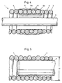
- Figure 4 schematically shows a portion of a guide wire according to the invention, and
- Figure 5 schematically shows a section of a guide wire according to a variant.
Die Figur 4 zeigt einen Abschnitt eines Führungsdrahtes 1, der mit Ausnahme der hier gezeigten Verbindungsstelle 8 genau demjenigen nach der oben erwähnten EP-A-0 625 358 entsprechen kann. Diese Schrift wird hier für die Offenbarung beigezogen. In Figur 4 ist das hier nicht gezeigte distale Ende rechts und das proximale Ende links. Der Führungsdraht 1 weist einen flexiblen Schaft 3 auf, der am hier nicht gezeigten distalen Ende verjüngt und flachgeschlagen sowie mit der hier ebenfalls nicht gezeigten Spitze fest verbunden ist. Der Schaft 3 bildet einen Kerndraht und ist über seine gesamte Länge von einer ebenfalls flexiblen Spirale 2 umgeben, die eine proximale Spiralfeder 4 und eine distale Spiralfeder 5 aufweist, die an einer Verbindungsstelle 8 fest miteinander verbunden sind. Die Spirale 4 besteht vorzugsweise aus einem rostfreien Draht mit einem Durchmesser von beispielsweise etwa 0,06 mm. Der Aussendurchmesser C (Figur 2) dieser Spiralfeder 4 beträgt vorzugsweise etwa 0,31 - 0,32 mm. Die distale Spiralfeder 5 ist aus einem röntensichtbaren Werkstoff, beispielsweise Wolfram hergestellt und besitzt einen Aussendurchmesser D von vorzugsweise etwa 0,31 mm. Die Spiralfeder 5 ist aus einem Draht gewunden, der einen Durchmesser von beispielsweise etwa 0,05 mm aufweist.FIG. 4 shows a section of a guide wire 1 which, with the exception of the
Nachfolgend wird das Verbinden der beiden Spiralfedern 4 und 5 anhand der Figuren 1 bis 3 näher erläutert.The connection of the two
Um die beiden Spiralfedern 4 und 5 miteinander fest zu verbinden, werden an den zu verbindenden Enden einige Windungen, vorzugsweise 2 bis 5 Windungen 4a und 5a geöffnet und zusammengedreht. Hierbei werden die beiden Spiralfedern 4 und 5 vorzugsweise auf eine Zentrierfomr 7 aufgezogen, das eine Zentrierform bildet. Der Aussendurchmesser A der Zentrierform 7 ist gleich oder geringfügig kleiner als der Innendurchmesser B der Spiralfedern 4 und 5. Beim Zusammendrehen können die Spiralen infolge der Führung der Zentrierform seitlich nicht weglaufen.In order to firmly connect the two
Die Figur 2 zeigt die beiden Spiralfedern 4 und 5 nach dem Zusammendrehen der aufgeweiteten Windungen 4a und 5a. Auf diese Windungen 4a und 5a wird nun gemäss Figur 3 Lot 6 rundum aufgetragen. Dieses Lot dringt in die Zwischenräume dieser Windungen 4a und 5a ein und umschliesst die Zentrierform 7 an seiner glatt und zylindrischen Aussenseite 7a im Bereich der genannten Windungen 4a und 5a. Diese Zentrierform 7 ist nun vorzugsweise so ausgebildet, dass es das verwendete Lot nicht annimmt und sich auch nicht mit diesem verbindet. Vorzugsweise besteht die Zentrierform aus einer Nickel-Titan-Legierung, beispielsweise Tynel oder NiTi-Legierung. Möglich sind jedoch auch andere geeignete Legierungen aus Wolfram oder Molybdän. Diese Legierungen nehmen das Lot 6 nicht an und ergibt ein flexibles Draht- und Rohrstück 7. Nach dem Verlöten kann die Zentrierform 7 ohne Beschädigung der Verbindungsstelle 8 sehr einfach von der Spirale 2 abgezogen werden. Die beiden Spiralfedern 4 und 5 sind nun an der Verbindungsstelle 8 fest miteinander verbunden. Die Innenseite 6d der Verbindungsstelle 8 ist glatt und zylindrisch und zwar korrespondierend der Aussenseite 7a der Zentrierform 7. Die Verbindungsstelle 8 ist ebenfalls zylindrisch und überragt die Aussenseite der Spirale 2 im wesentlichen nicht.FIG. 2 shows the two
Nach dem Entfernen der Zentrierform 7 wird der Schaft 3 in die Spirale 2 eingesetzt und in bekannter Weise mit der Spitze verbunden. Wesentlich ist nun, dass das Einführen des Schaftes 3 durch die Verbindungsstelle 8 nicht behindert wird, da diese innen ebenso weit ist wie die Spirale 2 vor und nach diesem Bereich. Die Spirale 2 lässt sich somit ohne Schaft 3 vormontieren und an Lager legen.After removing the centering
Wie oben erwähnt, ist die distale Spiralfeder 5 aus einem Draht gewunden, der einen kleineren Durchmesser aufweist, als derjenige der proximalen Spiralfeder 4, was die Zeichnung ebenfalls erkennen lässt. Nach einer in Figur 5 dargestellten Weiterbildung der Erfindung ist der Durchmesser D' der distalen Spiralfeder 5 möglichst gross gewählt, aber doch so, dass die Aussenseite der Spiralfeder 5 in der hier gezeigten seitlich versetzten Lage aussenseitig nicht vorstehen kann, was eine optimal glatte Aussenseite im Bereich der Verbindungsstelle ergibt.As mentioned above, the
Claims (10)
Priority Applications (10)
| Application Number | Priority Date | Filing Date | Title |
|---|---|---|---|
| AT96106958T ATE164772T1 (en) | 1996-05-03 | 1996-05-03 | METHOD FOR PRODUCING A GUIDE WIRE AND GUIDE WIRE |
| DK96106958T DK0804937T3 (en) | 1996-05-03 | 1996-05-03 | Process for producing a guide wire and guide wire |
| EP96106958A EP0804937B1 (en) | 1996-05-03 | 1996-05-03 | Guidewire and its manufacturing procedure |
| ES96106958T ES2116798T3 (en) | 1996-05-03 | 1996-05-03 | GUIDED THREAD AND ITS MANUFACTURING PROCEDURE. |
| DE59600146T DE59600146D1 (en) | 1996-05-03 | 1996-05-03 | Method of making a guidewire and guidewire |
| CA002198314A CA2198314C (en) | 1996-05-03 | 1997-02-24 | Method of producing a guide wire and guide wire |
| JP08781497A JP3875762B2 (en) | 1996-05-03 | 1997-04-07 | Guide wire manufacturing method |
| AU17871/97A AU1787197A (en) | 1996-05-03 | 1997-04-14 | Method of producing a guide wire and guide wire |
| US08/837,404 US5951496A (en) | 1996-05-03 | 1997-04-15 | Guide wire and method of producing a guide wire |
| JP2006216992A JP2006297152A (en) | 1996-05-03 | 2006-08-09 | Guide wire |
Applications Claiming Priority (1)
| Application Number | Priority Date | Filing Date | Title |
|---|---|---|---|
| EP96106958A EP0804937B1 (en) | 1996-05-03 | 1996-05-03 | Guidewire and its manufacturing procedure |
Publications (2)
| Publication Number | Publication Date |
|---|---|
| EP0804937A1 true EP0804937A1 (en) | 1997-11-05 |
| EP0804937B1 EP0804937B1 (en) | 1998-04-08 |
Family
ID=8222738
Family Applications (1)
| Application Number | Title | Priority Date | Filing Date |
|---|---|---|---|
| EP96106958A Expired - Lifetime EP0804937B1 (en) | 1996-05-03 | 1996-05-03 | Guidewire and its manufacturing procedure |
Country Status (9)
| Country | Link |
|---|---|
| US (1) | US5951496A (en) |
| EP (1) | EP0804937B1 (en) |
| JP (2) | JP3875762B2 (en) |
| AT (1) | ATE164772T1 (en) |
| AU (1) | AU1787197A (en) |
| CA (1) | CA2198314C (en) |
| DE (1) | DE59600146D1 (en) |
| DK (1) | DK0804937T3 (en) |
| ES (1) | ES2116798T3 (en) |
Families Citing this family (25)
| Publication number | Priority date | Publication date | Assignee | Title |
|---|---|---|---|---|
| JP3426174B2 (en) | 1999-12-24 | 2003-07-14 | 朝日インテック株式会社 | Medical guidewire |
| US6599254B2 (en) * | 2000-05-08 | 2003-07-29 | R. Edward Winters | Multi-feature steerable guidewire for vascular systems |
| JP4497746B2 (en) * | 2001-04-10 | 2010-07-07 | ニプロ株式会社 | Guide wire |
| US6908448B2 (en) * | 2001-08-24 | 2005-06-21 | Dermisonics, Inc. | Substance delivery device |
| US20040064069A1 (en) * | 2002-09-30 | 2004-04-01 | Reynolds Brian R. | Medical device with support member |
| US8377035B2 (en) | 2003-01-17 | 2013-02-19 | Boston Scientific Scimed, Inc. | Unbalanced reinforcement members for medical device |
| JP4186689B2 (en) * | 2003-04-18 | 2008-11-26 | ニプロ株式会社 | Guide wire |
| JP4677205B2 (en) * | 2003-07-17 | 2011-04-27 | テルモ株式会社 | Guide wire |
| US7833175B2 (en) * | 2003-09-05 | 2010-11-16 | Boston Scientific Scimed, Inc. | Medical device coil |
| US7785273B2 (en) * | 2003-09-22 | 2010-08-31 | Boston Scientific Scimed, Inc. | Guidewire with reinforcing member |
| US7237313B2 (en) * | 2003-12-05 | 2007-07-03 | Boston Scientific Scimed, Inc. | Elongated medical device for intracorporal use |
| JP2006271955A (en) * | 2005-03-02 | 2006-10-12 | Terumo Corp | Guide wire |
| US8267872B2 (en) * | 2005-07-07 | 2012-09-18 | St. Jude Medical, Cardiology Division, Inc. | Steerable guide wire with torsionally stable tip |
| US20070185415A1 (en) * | 2005-07-07 | 2007-08-09 | Ressemann Thomas V | Steerable guide wire with torsionally stable tip |
| US7785317B2 (en) * | 2006-03-29 | 2010-08-31 | Codman & Shurtleff, Inc. | Joined metal tubing and method of manufacture |
| US20080051676A1 (en) * | 2006-08-24 | 2008-02-28 | Melsheimer Jeffry S | Extendable Wire Guide system |
| US7833013B2 (en) * | 2006-12-13 | 2010-11-16 | Diers Nelson R | Device, method and kit for determining orthodontic dimensions |
| US7841994B2 (en) | 2007-11-02 | 2010-11-30 | Boston Scientific Scimed, Inc. | Medical device for crossing an occlusion in a vessel |
| JP4913180B2 (en) * | 2009-07-02 | 2012-04-11 | 株式会社パテントストラ | Medical guide wire, method for manufacturing the same, and assembly of medical guide wire, balloon catheter, and guiding catheter |
| EP2402051B1 (en) | 2010-06-30 | 2019-10-02 | Asahi Intecc Co., Ltd. | Medical guide wire |
| JP5929315B2 (en) * | 2011-02-28 | 2016-06-01 | 住友ベークライト株式会社 | Medical device and method for manufacturing medical device |
| JP5360840B2 (en) * | 2011-03-31 | 2013-12-04 | 朝日インテック株式会社 | Guide wire |
| JP2013094343A (en) * | 2011-10-31 | 2013-05-20 | Asahi Intecc Co Ltd | Guide wire |
| JP6080170B2 (en) * | 2014-03-20 | 2017-02-15 | 朝日インテック株式会社 | Guide wire |
| US11285299B2 (en) * | 2019-10-31 | 2022-03-29 | Abbott Cardiovascular Systems Inc. | Mold for forming solder distal tip for guidewire |
Citations (7)
| Publication number | Priority date | Publication date | Assignee | Title |
|---|---|---|---|---|
| US4646044A (en) * | 1984-03-19 | 1987-02-24 | Mitsubishi Denki Kabushiki Kaisha | Bobbinless solenoid coil |
| US4748986A (en) | 1985-11-26 | 1988-06-07 | Advanced Cardiovascular Systems, Inc. | Floppy guide wire with opaque tip |
| US4934380A (en) * | 1987-11-27 | 1990-06-19 | Boston Scientific Corporation | Medical guidewire |
| EP0419277A1 (en) | 1989-09-22 | 1991-03-27 | Cardiometrics, Inc. | Guide wire for use in measuring a characteristic of liquid flow in a vessel |
| US5282478A (en) * | 1991-08-21 | 1994-02-01 | Baxter International, Inc. | Guidewire extension system with coil connectors |
| EP0625358A1 (en) | 1993-05-19 | 1994-11-23 | Schneider (Europe) Ag | Guide wire |
| US5415170A (en) * | 1992-09-23 | 1995-05-16 | Pilot Cardiovascular Systems, Inc. | Rotational atherectomy guidewire |
Family Cites Families (36)
| Publication number | Priority date | Publication date | Assignee | Title |
|---|---|---|---|---|
| US33911A (en) * | 1861-12-10 | Henry weissenboen | ||
| US4366076A (en) * | 1980-06-11 | 1982-12-28 | Ciba-Geigy Corporation | Corrosion inhibited compositions |
| US4545390A (en) * | 1982-09-22 | 1985-10-08 | C. R. Bard, Inc. | Steerable guide wire for balloon dilatation procedure |
| US4554929A (en) * | 1983-07-13 | 1985-11-26 | Advanced Cardiovascular Systems, Inc. | Catheter guide wire with short spring tip and method of using the same |
| US4538622A (en) * | 1983-11-10 | 1985-09-03 | Advanced Cardiovascular Systems, Inc. | Guide wire for catheters |
| US4721117A (en) * | 1986-04-25 | 1988-01-26 | Advanced Cardiovascular Systems, Inc. | Torsionally stabilized guide wire with outer jacket |
| US4676249A (en) * | 1986-05-19 | 1987-06-30 | Cordis Corporation | Multi-mode guidewire |
| US4763647A (en) * | 1987-01-06 | 1988-08-16 | C. R. Bard, Inc. | Dual coil steerable guidewire |
| US4757827A (en) * | 1987-02-17 | 1988-07-19 | Versaflex Delivery Systems Inc. | Steerable guidewire with deflectable tip |
| US5165421A (en) * | 1987-09-30 | 1992-11-24 | Lake Region Manufacturing Co., Inc. | Hollow lumen cable apparatus |
| US4830023A (en) * | 1987-11-27 | 1989-05-16 | Medi-Tech, Incorporated | Medical guidewire |
| US5067489A (en) * | 1988-08-16 | 1991-11-26 | Flexmedics Corporation | Flexible guide with safety tip |
| US4886067A (en) * | 1989-01-03 | 1989-12-12 | C. R. Bard, Inc. | Steerable guidewire with soft adjustable tip |
| US4966163A (en) * | 1989-02-14 | 1990-10-30 | Advanced Cardiovascular Systems, Inc. | Extendable guidewire for vascular procedures |
| US4922924A (en) * | 1989-04-27 | 1990-05-08 | C. R. Bard, Inc. | Catheter guidewire with varying radiopacity |
| US5063935A (en) * | 1989-04-27 | 1991-11-12 | C. R. Bard, Inc. | Catheter guidewire with varying radiopacity |
| US5144959A (en) * | 1989-08-15 | 1992-09-08 | C. R. Bard, Inc. | Catheter guidewire with varying radiopacity |
| DE3931350A1 (en) * | 1989-09-20 | 1991-03-28 | Kaltenbach Martin | GUIDE SLEEVE FOR IMPORTING CATHETERS |
| US5084022A (en) * | 1989-10-04 | 1992-01-28 | Lake Region Manufacturing Company, Inc. | Graduated guidewire |
| US5060660A (en) * | 1990-02-28 | 1991-10-29 | C. R. Bard, Inc. | Steerable extendable guidewire with adjustable tip |
| US5147317A (en) * | 1990-06-04 | 1992-09-15 | C.R. Bard, Inc. | Low friction varied radiopacity guidewire |
| DE69129539T2 (en) * | 1990-08-29 | 1999-03-04 | Advanced Cardiovascular System | TWO SPIRAL SPRING GUIDE WIRE WITH RADIANT IMPERATIVE DISTAL TIP |
| US5211636A (en) * | 1990-10-31 | 1993-05-18 | Lake Region Manufacturing Co., Inc. | Steerable infusion guide wire |
| US5174302A (en) * | 1990-12-04 | 1992-12-29 | Cordis Corporation | Variable radiopacity guidewire with spaced highly radiopaque regions |
| US5109867A (en) * | 1991-04-19 | 1992-05-05 | Target Therapeutics | Extendable guidewire assembly |
| US5228453A (en) * | 1991-05-07 | 1993-07-20 | Target Therapeutics, Inc. | Catheter guide wire |
| US5271415A (en) * | 1992-01-28 | 1993-12-21 | Baxter International Inc. | Guidewire extension system |
| US5259393A (en) * | 1992-05-13 | 1993-11-09 | Cordis Corporation | Guidewire having controlled radiopacity tip |
| US5267574A (en) * | 1992-09-10 | 1993-12-07 | Cordis Corporation | Guidewire with spring and a heat shrinkable connection |
| US5377690A (en) * | 1993-02-09 | 1995-01-03 | C. R. Bard, Inc. | Guidewire with round forming wire |
| US5520194A (en) * | 1993-12-07 | 1996-05-28 | Asahi Intecc Co., Ltd. | Guide wire for medical purpose and manufacturing process of coil thereof |
| US5666969A (en) * | 1994-05-18 | 1997-09-16 | Scimed Life Systems, Inc. | Guidewire having multiple radioscopic coils |
| US5664580A (en) * | 1995-01-31 | 1997-09-09 | Microvena Corporation | Guidewire having bimetallic coil |
| US5640970A (en) * | 1995-04-26 | 1997-06-24 | Cordis Corporation | Guidewire having a controlled radiopacity tip |
| US5551444A (en) * | 1995-05-31 | 1996-09-03 | Radius Medical Technologies, Inc. | Flexible guidewire with radiopaque outer coil and non-radiopaque inner coil |
| US5682894A (en) * | 1996-04-26 | 1997-11-04 | Orr; Gregory C. | Guide wire |
-
1996
- 1996-05-03 DE DE59600146T patent/DE59600146D1/en not_active Expired - Lifetime
- 1996-05-03 DK DK96106958T patent/DK0804937T3/en active
- 1996-05-03 AT AT96106958T patent/ATE164772T1/en not_active IP Right Cessation
- 1996-05-03 ES ES96106958T patent/ES2116798T3/en not_active Expired - Lifetime
- 1996-05-03 EP EP96106958A patent/EP0804937B1/en not_active Expired - Lifetime
-
1997
- 1997-02-24 CA CA002198314A patent/CA2198314C/en not_active Expired - Fee Related
- 1997-04-07 JP JP08781497A patent/JP3875762B2/en not_active Expired - Fee Related
- 1997-04-14 AU AU17871/97A patent/AU1787197A/en not_active Abandoned
- 1997-04-15 US US08/837,404 patent/US5951496A/en not_active Expired - Lifetime
-
2006
- 2006-08-09 JP JP2006216992A patent/JP2006297152A/en not_active Withdrawn
Patent Citations (7)
| Publication number | Priority date | Publication date | Assignee | Title |
|---|---|---|---|---|
| US4646044A (en) * | 1984-03-19 | 1987-02-24 | Mitsubishi Denki Kabushiki Kaisha | Bobbinless solenoid coil |
| US4748986A (en) | 1985-11-26 | 1988-06-07 | Advanced Cardiovascular Systems, Inc. | Floppy guide wire with opaque tip |
| US4934380A (en) * | 1987-11-27 | 1990-06-19 | Boston Scientific Corporation | Medical guidewire |
| EP0419277A1 (en) | 1989-09-22 | 1991-03-27 | Cardiometrics, Inc. | Guide wire for use in measuring a characteristic of liquid flow in a vessel |
| US5282478A (en) * | 1991-08-21 | 1994-02-01 | Baxter International, Inc. | Guidewire extension system with coil connectors |
| US5415170A (en) * | 1992-09-23 | 1995-05-16 | Pilot Cardiovascular Systems, Inc. | Rotational atherectomy guidewire |
| EP0625358A1 (en) | 1993-05-19 | 1994-11-23 | Schneider (Europe) Ag | Guide wire |
Also Published As
| Publication number | Publication date |
|---|---|
| ATE164772T1 (en) | 1998-04-15 |
| JP2006297152A (en) | 2006-11-02 |
| ES2116798T3 (en) | 1998-07-16 |
| AU1787197A (en) | 1997-11-06 |
| DE59600146D1 (en) | 1998-05-14 |
| DK0804937T3 (en) | 1999-01-11 |
| EP0804937B1 (en) | 1998-04-08 |
| JPH1043307A (en) | 1998-02-17 |
| CA2198314C (en) | 2007-03-06 |
| US5951496A (en) | 1999-09-14 |
| JP3875762B2 (en) | 2007-01-31 |
| CA2198314A1 (en) | 1997-11-04 |
Similar Documents
| Publication | Publication Date | Title |
|---|---|---|
| EP0804937B1 (en) | Guidewire and its manufacturing procedure | |
| EP0625358B1 (en) | Guide wire | |
| DE69834265T2 (en) | GUIDE WIRE | |
| DE60016676T2 (en) | Medical guidewire | |
| EP0401158B1 (en) | Catheter apparatus with a guide wire and method for the production of such a guide wire | |
| DE69630119T2 (en) | FLEXIBLE GUIDE WIRE WITH AN OUTER RADIATION TRANSMITTING SPIRAL SPRING AND AN INNER RADIATION TRANSMITTING SPRING SPRING | |
| DE60224767T2 (en) | Medical guidewire | |
| DE60021543T2 (en) | A SCREW-WRAPPED GUIDE WIRE | |
| DE69729633T2 (en) | IMPLANTABLE DEVICE FOR SUSTAINING OR RESTORING A NORMAL BODY VESSEL CROSS SECTION | |
| DE19919375B4 (en) | Forked stent with improved side branch opening | |
| DE69632006T2 (en) | Guide wire unit | |
| DE69921908T2 (en) | Balloon catheter with elastic filling for supporting a stent | |
| EP0843990B1 (en) | Balloon catheter and delivery device for a stent | |
| DE69735781T2 (en) | guidewire | |
| DE69629593T2 (en) | CATHETER WITH AN ELECTRIC GUIDE SENSOR | |
| DE69722738T2 (en) | Guidewire with radiopaque distal tip | |
| DE60017962T2 (en) | Clamping device for clamping a line | |
| DE69636213T2 (en) | Hollow wound guidewire for a catheter | |
| DE69633265T2 (en) | Guide wire unit | |
| DE60112173T2 (en) | Production method for branching stent with improved secondary opening | |
| DE3812022A1 (en) | CATHETER GUIDE WIRE | |
| DE69720964T2 (en) | Guide wire with pressure indicator and method for producing such a guide wire | |
| DE3643362A1 (en) | PROBE FOR INTRODUCTION IN HUMAN OR ANIMAL BODIES, IN PARTICULAR PAPILLOTOM | |
| DE69636833T2 (en) | CATHETER FOR THE LEFT CORONATERY | |
| DE3502322C2 (en) |
Legal Events
| Date | Code | Title | Description |
|---|---|---|---|
| GRAG | Despatch of communication of intention to grant |
Free format text: ORIGINAL CODE: EPIDOS AGRA |
|
| PUAI | Public reference made under article 153(3) epc to a published international application that has entered the european phase |
Free format text: ORIGINAL CODE: 0009012 |
|
| GRAG | Despatch of communication of intention to grant |
Free format text: ORIGINAL CODE: EPIDOS AGRA |
|
| GRAH | Despatch of communication of intention to grant a patent |
Free format text: ORIGINAL CODE: EPIDOS IGRA |
|
| 17P | Request for examination filed |
Effective date: 19960503 |
|
| AK | Designated contracting states |
Kind code of ref document: A1 Designated state(s): AT BE CH DE DK ES FR GB IE IT LI NL SE |
|
| RBV | Designated contracting states (corrected) |
Designated state(s): AT BE CH DE DK ES FR GB IE IT LI NL SE |
|
| GRAH | Despatch of communication of intention to grant a patent |
Free format text: ORIGINAL CODE: EPIDOS IGRA |
|
| GRAA | (expected) grant |
Free format text: ORIGINAL CODE: 0009210 |
|
| AK | Designated contracting states |
Kind code of ref document: B1 Designated state(s): AT BE CH DE DK ES FR GB IE IT LI NL SE |
|
| REF | Corresponds to: |
Ref document number: 164772 Country of ref document: AT Date of ref document: 19980415 Kind code of ref document: T |
|
| REG | Reference to a national code |
Ref country code: CH Ref legal event code: EP |
|
| REG | Reference to a national code |
Ref country code: CH Ref legal event code: NV Representative=s name: ISLER & PEDRAZZINI AG |
|
| RAP2 | Party data changed (patent owner data changed or rights of a patent transferred) |
Owner name: SCHNEIDER (EUROPE) GMBH |
|
| ITF | It: translation for a ep patent filed |
Owner name: STUDIO TORTA S.R.L. |
|
| REF | Corresponds to: |
Ref document number: 59600146 Country of ref document: DE Date of ref document: 19980514 |
|
| GBT | Gb: translation of ep patent filed (gb section 77(6)(a)/1977) |
Effective date: 19980506 |
|
| ET | Fr: translation filed | ||
| NLT2 | Nl: modifications (of names), taken from the european patent patent bulletin |
Owner name: SCHNEIDER (EUROPE) GMBH |
|
| REG | Reference to a national code |
Ref country code: ES Ref legal event code: FG2A Ref document number: 2116798 Country of ref document: ES Kind code of ref document: T3 |
|
| REG | Reference to a national code |
Ref country code: IE Ref legal event code: FG4D Free format text: 79782 |
|
| REG | Reference to a national code |
Ref country code: DK Ref legal event code: T3 |
|
| PLBE | No opposition filed within time limit |
Free format text: ORIGINAL CODE: 0009261 |
|
| STAA | Information on the status of an ep patent application or granted ep patent |
Free format text: STATUS: NO OPPOSITION FILED WITHIN TIME LIMIT |
|
| 26N | No opposition filed | ||
| PGFP | Annual fee paid to national office [announced via postgrant information from national office to epo] |
Ref country code: DK Payment date: 19990413 Year of fee payment: 4 |
|
| PGFP | Annual fee paid to national office [announced via postgrant information from national office to epo] |
Ref country code: AT Payment date: 19990415 Year of fee payment: 4 |
|
| PGFP | Annual fee paid to national office [announced via postgrant information from national office to epo] |
Ref country code: SE Payment date: 19990427 Year of fee payment: 4 |
|
| PGFP | Annual fee paid to national office [announced via postgrant information from national office to epo] |
Ref country code: BE Payment date: 19990517 Year of fee payment: 4 |
|
| PG25 | Lapsed in a contracting state [announced via postgrant information from national office to epo] |
Ref country code: DK Free format text: LAPSE BECAUSE OF NON-PAYMENT OF DUE FEES Effective date: 20000503 Ref country code: AT Free format text: LAPSE BECAUSE OF NON-PAYMENT OF DUE FEES Effective date: 20000503 |
|
| PG25 | Lapsed in a contracting state [announced via postgrant information from national office to epo] |
Ref country code: SE Free format text: LAPSE BECAUSE OF NON-PAYMENT OF DUE FEES Effective date: 20000504 |
|
| PG25 | Lapsed in a contracting state [announced via postgrant information from national office to epo] |
Ref country code: LI Free format text: LAPSE BECAUSE OF NON-PAYMENT OF DUE FEES Effective date: 20000531 Ref country code: CH Free format text: LAPSE BECAUSE OF NON-PAYMENT OF DUE FEES Effective date: 20000531 Ref country code: BE Free format text: LAPSE BECAUSE OF NON-PAYMENT OF DUE FEES Effective date: 20000531 |
|
| PGFP | Annual fee paid to national office [announced via postgrant information from national office to epo] |
Ref country code: ES Payment date: 20000608 Year of fee payment: 5 |
|
| BERE | Be: lapsed |
Owner name: SCHNEIDER (EUROPE) A.G. Effective date: 20000531 |
|
| REG | Reference to a national code |
Ref country code: CH Ref legal event code: PL |
|
| EUG | Se: european patent has lapsed |
Ref document number: 96106958.0 |
|
| REG | Reference to a national code |
Ref country code: DK Ref legal event code: EBP |
|
| PG25 | Lapsed in a contracting state [announced via postgrant information from national office to epo] |
Ref country code: ES Free format text: LAPSE BECAUSE OF NON-PAYMENT OF DUE FEES Effective date: 20010504 |
|
| REG | Reference to a national code |
Ref country code: GB Ref legal event code: IF02 |
|
| REG | Reference to a national code |
Ref country code: ES Ref legal event code: FD2A Effective date: 20030303 |
|
| PG25 | Lapsed in a contracting state [announced via postgrant information from national office to epo] |
Ref country code: IT Free format text: LAPSE BECAUSE OF NON-PAYMENT OF DUE FEES Effective date: 20050503 |
|
| PGFP | Annual fee paid to national office [announced via postgrant information from national office to epo] |
Ref country code: FR Payment date: 20100525 Year of fee payment: 15 |
|
| PGFP | Annual fee paid to national office [announced via postgrant information from national office to epo] |
Ref country code: GB Payment date: 20100401 Year of fee payment: 15 |
|
| PGFP | Annual fee paid to national office [announced via postgrant information from national office to epo] |
Ref country code: IE Payment date: 20110427 Year of fee payment: 16 |
|
| PGFP | Annual fee paid to national office [announced via postgrant information from national office to epo] |
Ref country code: NL Payment date: 20110523 Year of fee payment: 16 |
|
| PGFP | Annual fee paid to national office [announced via postgrant information from national office to epo] |
Ref country code: DE Payment date: 20110531 Year of fee payment: 16 |
|
| GBPC | Gb: european patent ceased through non-payment of renewal fee |
Effective date: 20110503 |
|
| REG | Reference to a national code |
Ref country code: FR Ref legal event code: ST Effective date: 20120131 |
|
| PG25 | Lapsed in a contracting state [announced via postgrant information from national office to epo] |
Ref country code: FR Free format text: LAPSE BECAUSE OF NON-PAYMENT OF DUE FEES Effective date: 20110531 |
|
| PG25 | Lapsed in a contracting state [announced via postgrant information from national office to epo] |
Ref country code: GB Free format text: LAPSE BECAUSE OF NON-PAYMENT OF DUE FEES Effective date: 20110503 |
|
| REG | Reference to a national code |
Ref country code: NL Ref legal event code: V1 Effective date: 20121201 |
|
| REG | Reference to a national code |
Ref country code: IE Ref legal event code: MM4A |
|
| REG | Reference to a national code |
Ref country code: DE Ref legal event code: R119 Ref document number: 59600146 Country of ref document: DE Effective date: 20121201 |
|
| PG25 | Lapsed in a contracting state [announced via postgrant information from national office to epo] |
Ref country code: NL Free format text: LAPSE BECAUSE OF NON-PAYMENT OF DUE FEES Effective date: 20121201 |
|
| PG25 | Lapsed in a contracting state [announced via postgrant information from national office to epo] |
Ref country code: IE Free format text: LAPSE BECAUSE OF NON-PAYMENT OF DUE FEES Effective date: 20120503 |
|
| PG25 | Lapsed in a contracting state [announced via postgrant information from national office to epo] |
Ref country code: DE Free format text: LAPSE BECAUSE OF NON-PAYMENT OF DUE FEES Effective date: 20121201 |