EP0804906B1 - Endovascular electrolytically detachable wire for thrombus formation - Google Patents
Endovascular electrolytically detachable wire for thrombus formation Download PDFInfo
- Publication number
- EP0804906B1 EP0804906B1 EP97112838A EP97112838A EP0804906B1 EP 0804906 B1 EP0804906 B1 EP 0804906B1 EP 97112838 A EP97112838 A EP 97112838A EP 97112838 A EP97112838 A EP 97112838A EP 0804906 B1 EP0804906 B1 EP 0804906B1
- Authority
- EP
- European Patent Office
- Prior art keywords
- wire
- tip
- coil
- aneurysm
- tip portion
- Prior art date
- Legal status (The legal status is an assumption and is not a legal conclusion. Google has not performed a legal analysis and makes no representation as to the accuracy of the status listed.)
- Expired - Lifetime
Links
- 0 CC1(CC1)C1C*CC1 Chemical compound CC1(CC1)C1C*CC1 0.000 description 1
Images


Classifications
-
- A—HUMAN NECESSITIES
- A61—MEDICAL OR VETERINARY SCIENCE; HYGIENE
- A61M—DEVICES FOR INTRODUCING MEDIA INTO, OR ONTO, THE BODY; DEVICES FOR TRANSDUCING BODY MEDIA OR FOR TAKING MEDIA FROM THE BODY; DEVICES FOR PRODUCING OR ENDING SLEEP OR STUPOR
- A61M25/00—Catheters; Hollow probes
- A61M25/01—Introducing, guiding, advancing, emplacing or holding catheters
- A61M25/09—Guide wires
-
- A—HUMAN NECESSITIES
- A61—MEDICAL OR VETERINARY SCIENCE; HYGIENE
- A61B—DIAGNOSIS; SURGERY; IDENTIFICATION
- A61B17/00—Surgical instruments, devices or methods, e.g. tourniquets
- A61B17/12—Surgical instruments, devices or methods, e.g. tourniquets for ligaturing or otherwise compressing tubular parts of the body, e.g. blood vessels, umbilical cord
- A61B17/12022—Occluding by internal devices, e.g. balloons or releasable wires
- A61B17/12099—Occluding by internal devices, e.g. balloons or releasable wires characterised by the location of the occluder
- A61B17/12109—Occluding by internal devices, e.g. balloons or releasable wires characterised by the location of the occluder in a blood vessel
- A61B17/12113—Occluding by internal devices, e.g. balloons or releasable wires characterised by the location of the occluder in a blood vessel within an aneurysm
-
- A—HUMAN NECESSITIES
- A61—MEDICAL OR VETERINARY SCIENCE; HYGIENE
- A61B—DIAGNOSIS; SURGERY; IDENTIFICATION
- A61B17/00—Surgical instruments, devices or methods, e.g. tourniquets
- A61B17/12—Surgical instruments, devices or methods, e.g. tourniquets for ligaturing or otherwise compressing tubular parts of the body, e.g. blood vessels, umbilical cord
- A61B17/12022—Occluding by internal devices, e.g. balloons or releasable wires
- A61B17/12131—Occluding by internal devices, e.g. balloons or releasable wires characterised by the type of occluding device
- A61B17/1214—Coils or wires
- A61B17/12145—Coils or wires having a pre-set deployed three-dimensional shape
-
- A—HUMAN NECESSITIES
- A61—MEDICAL OR VETERINARY SCIENCE; HYGIENE
- A61B—DIAGNOSIS; SURGERY; IDENTIFICATION
- A61B17/00—Surgical instruments, devices or methods, e.g. tourniquets
- A61B17/12—Surgical instruments, devices or methods, e.g. tourniquets for ligaturing or otherwise compressing tubular parts of the body, e.g. blood vessels, umbilical cord
- A61B17/12022—Occluding by internal devices, e.g. balloons or releasable wires
- A61B17/12131—Occluding by internal devices, e.g. balloons or releasable wires characterised by the type of occluding device
- A61B17/1214—Coils or wires
- A61B17/1215—Coils or wires comprising additional materials, e.g. thrombogenic, having filaments, having fibers, being coated
-
- A—HUMAN NECESSITIES
- A61—MEDICAL OR VETERINARY SCIENCE; HYGIENE
- A61B—DIAGNOSIS; SURGERY; IDENTIFICATION
- A61B18/00—Surgical instruments, devices or methods for transferring non-mechanical forms of energy to or from the body
- A61B18/04—Surgical instruments, devices or methods for transferring non-mechanical forms of energy to or from the body by heating
- A61B18/12—Surgical instruments, devices or methods for transferring non-mechanical forms of energy to or from the body by heating by passing a current through the tissue to be heated, e.g. high-frequency current
- A61B18/14—Probes or electrodes therefor
- A61B18/1492—Probes or electrodes therefor having a flexible, catheter-like structure, e.g. for heart ablation
-
- A—HUMAN NECESSITIES
- A61—MEDICAL OR VETERINARY SCIENCE; HYGIENE
- A61B—DIAGNOSIS; SURGERY; IDENTIFICATION
- A61B17/00—Surgical instruments, devices or methods, e.g. tourniquets
- A61B17/00234—Surgical instruments, devices or methods, e.g. tourniquets for minimally invasive surgery
- A61B2017/00292—Surgical instruments, devices or methods, e.g. tourniquets for minimally invasive surgery mounted on or guided by flexible, e.g. catheter-like, means
-
- A—HUMAN NECESSITIES
- A61—MEDICAL OR VETERINARY SCIENCE; HYGIENE
- A61B—DIAGNOSIS; SURGERY; IDENTIFICATION
- A61B17/00—Surgical instruments, devices or methods, e.g. tourniquets
- A61B17/12—Surgical instruments, devices or methods, e.g. tourniquets for ligaturing or otherwise compressing tubular parts of the body, e.g. blood vessels, umbilical cord
- A61B17/12022—Occluding by internal devices, e.g. balloons or releasable wires
- A61B2017/1205—Introduction devices
- A61B2017/12054—Details concerning the detachment of the occluding device from the introduction device
- A61B2017/12063—Details concerning the detachment of the occluding device from the introduction device electrolytically detachable
-
- A—HUMAN NECESSITIES
- A61—MEDICAL OR VETERINARY SCIENCE; HYGIENE
- A61B—DIAGNOSIS; SURGERY; IDENTIFICATION
- A61B17/00—Surgical instruments, devices or methods, e.g. tourniquets
- A61B17/12—Surgical instruments, devices or methods, e.g. tourniquets for ligaturing or otherwise compressing tubular parts of the body, e.g. blood vessels, umbilical cord
- A61B17/12022—Occluding by internal devices, e.g. balloons or releasable wires
- A61B2017/1205—Introduction devices
- A61B2017/12054—Details concerning the detachment of the occluding device from the introduction device
- A61B2017/12095—Threaded connection
-
- A—HUMAN NECESSITIES
- A61—MEDICAL OR VETERINARY SCIENCE; HYGIENE
- A61B—DIAGNOSIS; SURGERY; IDENTIFICATION
- A61B17/00—Surgical instruments, devices or methods, e.g. tourniquets
- A61B17/22—Implements for squeezing-off ulcers or the like on the inside of inner organs of the body; Implements for scraping-out cavities of body organs, e.g. bones; Calculus removers; Calculus smashing apparatus; Apparatus for removing obstructions in blood vessels, not otherwise provided for
- A61B2017/22038—Implements for squeezing-off ulcers or the like on the inside of inner organs of the body; Implements for scraping-out cavities of body organs, e.g. bones; Calculus removers; Calculus smashing apparatus; Apparatus for removing obstructions in blood vessels, not otherwise provided for with a guide wire
-
- A—HUMAN NECESSITIES
- A61—MEDICAL OR VETERINARY SCIENCE; HYGIENE
- A61B—DIAGNOSIS; SURGERY; IDENTIFICATION
- A61B18/00—Surgical instruments, devices or methods for transferring non-mechanical forms of energy to or from the body
- A61B2018/00636—Sensing and controlling the application of energy
- A61B2018/00666—Sensing and controlling the application of energy using a threshold value
- A61B2018/00678—Sensing and controlling the application of energy using a threshold value upper
-
- A—HUMAN NECESSITIES
- A61—MEDICAL OR VETERINARY SCIENCE; HYGIENE
- A61B—DIAGNOSIS; SURGERY; IDENTIFICATION
- A61B18/00—Surgical instruments, devices or methods for transferring non-mechanical forms of energy to or from the body
- A61B2018/00636—Sensing and controlling the application of energy
- A61B2018/00696—Controlled or regulated parameters
- A61B2018/00761—Duration
-
- A—HUMAN NECESSITIES
- A61—MEDICAL OR VETERINARY SCIENCE; HYGIENE
- A61B—DIAGNOSIS; SURGERY; IDENTIFICATION
- A61B18/00—Surgical instruments, devices or methods for transferring non-mechanical forms of energy to or from the body
- A61B2018/00636—Sensing and controlling the application of energy
- A61B2018/00773—Sensed parameters
- A61B2018/00875—Resistance or impedance
-
- A—HUMAN NECESSITIES
- A61—MEDICAL OR VETERINARY SCIENCE; HYGIENE
- A61B—DIAGNOSIS; SURGERY; IDENTIFICATION
- A61B18/00—Surgical instruments, devices or methods for transferring non-mechanical forms of energy to or from the body
- A61B2018/00636—Sensing and controlling the application of energy
- A61B2018/00773—Sensed parameters
- A61B2018/00886—Duration
-
- A—HUMAN NECESSITIES
- A61—MEDICAL OR VETERINARY SCIENCE; HYGIENE
- A61B—DIAGNOSIS; SURGERY; IDENTIFICATION
- A61B18/00—Surgical instruments, devices or methods for transferring non-mechanical forms of energy to or from the body
- A61B18/04—Surgical instruments, devices or methods for transferring non-mechanical forms of energy to or from the body by heating
- A61B18/12—Surgical instruments, devices or methods for transferring non-mechanical forms of energy to or from the body by heating by passing a current through the tissue to be heated, e.g. high-frequency current
- A61B18/1206—Generators therefor
- A61B2018/1226—Generators therefor powered by a battery
-
- A—HUMAN NECESSITIES
- A61—MEDICAL OR VETERINARY SCIENCE; HYGIENE
- A61B—DIAGNOSIS; SURGERY; IDENTIFICATION
- A61B18/00—Surgical instruments, devices or methods for transferring non-mechanical forms of energy to or from the body
- A61B18/04—Surgical instruments, devices or methods for transferring non-mechanical forms of energy to or from the body by heating
- A61B18/12—Surgical instruments, devices or methods for transferring non-mechanical forms of energy to or from the body by heating by passing a current through the tissue to be heated, e.g. high-frequency current
- A61B18/1206—Generators therefor
- A61B2018/1246—Generators therefor characterised by the output polarity
- A61B2018/1253—Generators therefor characterised by the output polarity monopolar
-
- A—HUMAN NECESSITIES
- A61—MEDICAL OR VETERINARY SCIENCE; HYGIENE
- A61B—DIAGNOSIS; SURGERY; IDENTIFICATION
- A61B18/00—Surgical instruments, devices or methods for transferring non-mechanical forms of energy to or from the body
- A61B18/04—Surgical instruments, devices or methods for transferring non-mechanical forms of energy to or from the body by heating
- A61B18/12—Surgical instruments, devices or methods for transferring non-mechanical forms of energy to or from the body by heating by passing a current through the tissue to be heated, e.g. high-frequency current
- A61B18/1206—Generators therefor
- A61B2018/1246—Generators therefor characterised by the output polarity
- A61B2018/126—Generators therefor characterised by the output polarity bipolar
-
- A—HUMAN NECESSITIES
- A61—MEDICAL OR VETERINARY SCIENCE; HYGIENE
- A61B—DIAGNOSIS; SURGERY; IDENTIFICATION
- A61B18/00—Surgical instruments, devices or methods for transferring non-mechanical forms of energy to or from the body
- A61B18/04—Surgical instruments, devices or methods for transferring non-mechanical forms of energy to or from the body by heating
- A61B18/12—Surgical instruments, devices or methods for transferring non-mechanical forms of energy to or from the body by heating by passing a current through the tissue to be heated, e.g. high-frequency current
- A61B18/1206—Generators therefor
- A61B2018/1266—Generators therefor with DC current output
-
- A—HUMAN NECESSITIES
- A61—MEDICAL OR VETERINARY SCIENCE; HYGIENE
- A61B—DIAGNOSIS; SURGERY; IDENTIFICATION
- A61B18/00—Surgical instruments, devices or methods for transferring non-mechanical forms of energy to or from the body
- A61B18/04—Surgical instruments, devices or methods for transferring non-mechanical forms of energy to or from the body by heating
- A61B18/12—Surgical instruments, devices or methods for transferring non-mechanical forms of energy to or from the body by heating by passing a current through the tissue to be heated, e.g. high-frequency current
- A61B18/14—Probes or electrodes therefor
- A61B2018/1405—Electrodes having a specific shape
- A61B2018/1435—Spiral
-
- A—HUMAN NECESSITIES
- A61—MEDICAL OR VETERINARY SCIENCE; HYGIENE
- A61B—DIAGNOSIS; SURGERY; IDENTIFICATION
- A61B18/00—Surgical instruments, devices or methods for transferring non-mechanical forms of energy to or from the body
- A61B18/04—Surgical instruments, devices or methods for transferring non-mechanical forms of energy to or from the body by heating
- A61B18/12—Surgical instruments, devices or methods for transferring non-mechanical forms of energy to or from the body by heating by passing a current through the tissue to be heated, e.g. high-frequency current
- A61B18/14—Probes or electrodes therefor
- A61B2018/1495—Electrodes being detachable from a support structure
-
- A—HUMAN NECESSITIES
- A61—MEDICAL OR VETERINARY SCIENCE; HYGIENE
- A61B—DIAGNOSIS; SURGERY; IDENTIFICATION
- A61B90/00—Instruments, implements or accessories specially adapted for surgery or diagnosis and not covered by any of the groups A61B1/00 - A61B50/00, e.g. for luxation treatment or for protecting wound edges
- A61B90/39—Markers, e.g. radio-opaque or breast lesions markers
- A61B2090/3966—Radiopaque markers visible in an X-ray image
-
- A—HUMAN NECESSITIES
- A61—MEDICAL OR VETERINARY SCIENCE; HYGIENE
- A61B—DIAGNOSIS; SURGERY; IDENTIFICATION
- A61B90/00—Instruments, implements or accessories specially adapted for surgery or diagnosis and not covered by any of the groups A61B1/00 - A61B50/00, e.g. for luxation treatment or for protecting wound edges
- A61B90/39—Markers, e.g. radio-opaque or breast lesions markers
-
- A—HUMAN NECESSITIES
- A61—MEDICAL OR VETERINARY SCIENCE; HYGIENE
- A61M—DEVICES FOR INTRODUCING MEDIA INTO, OR ONTO, THE BODY; DEVICES FOR TRANSDUCING BODY MEDIA OR FOR TAKING MEDIA FROM THE BODY; DEVICES FOR PRODUCING OR ENDING SLEEP OR STUPOR
- A61M25/00—Catheters; Hollow probes
- A61M25/01—Introducing, guiding, advancing, emplacing or holding catheters
- A61M25/09—Guide wires
- A61M2025/09175—Guide wires having specific characteristics at the distal tip
Definitions
- the invention relates to a wire for use in combination with a microcatheter to form an occlusion within a vascular novelty.
- the extravascular approach is comprised of surgery or microsurgery of the aneurysm or treatment site for the purpose of preserving the parent artery.
- This treatment is common with intracranial berry aneurysms.
- the methodology comprises the step of clipping the neck of the aneurysm, performing a suture-ligation of the neck, or wrapping the entire aneurysm.
- Each of these surgical procedures is performed by intrusive invasion into the body and performed from outside the aneurysm or target site.
- General anaesthesia, craniotomy, brain retraction and arachnoid dissection around the neck of the aneurysm and placement of a clip are typically required in these surgical procedures.
- Surgical treatment of vascular intracranial aneurysm can expect a mortality rate of 4-8% with a morbidity rate of 18-20%. Because of the mortality and morbidity rate expected, the surgical procedure is often delayed while waiting for the best surgical time with the result that an additional percentage of patients will die from the underlying disease or defect prior to surgery. For this reason the prior art has sought alternative means of treatment.
- microcatheters In the endovascular approach, the interior of the aneurysm is entered through the use of a microcatheter. Recently developed microcatheters, such as those shown by Engelson , “Catheter Guidewire”, U.S. Patent 4,884,579 and as described in Engelson , “Catheter for Guidewire Tracking", U.S. Patent 4,739,768 (1988), allow navigation into the cerebral arteries and entry into a cranial aneurysm.
- a balloon is typically attached to the end of the microcatheter and it is possible to introduce the balloon into the aneurysm, inflate it, and detach it, leaving it to occlude the sac and neck with preservation of the parent artery.
- endovascular balloon embolization of berry aneurysms is an attractive method in situations where an extravascular surgical approach is difficult, inflation of a balloon into the aneurysm carries some risk of aneurysm rupture due to possible over-distention of portions of the sac and due to the traction produced while detaching the balloon.
- an ideal embolizing agent should adapt itself to the irregular shape of the internal walls of the aneurysm.
- the aneurysmal wall must conform to the shape of the balloon. This may not lead to a satisfactory result and further increases the risk of rupture.
- balloon embolization is not always possible. If the diameter of the deflated balloon is too great to enter the intracerebral arteries, especially in the cases where there is a vasospasm, complications with ruptured intracranial aneurysms may occur. The procedure then must be deferred until the spasm is resolved and this then incurs a risk of rebleeding.
- an aneurysm is surgically exposed or stereotaxically reached with a probe.
- the wall of the aneurysm is then perforated from the outside and various techniques are used to occlude the interior in order to prevent it from rebleeding.
- These prior art techniques include electrothrombosis, isobutyl-cyanoacrylate embolization, hog-hair embolization and ferromagnetic thrombosis.
- the tip of a positively charged electrode is inserted surgically into the interior of the aneurysm.
- An application of the positive charge attracts white blood cells, red blood cells, platelets and fibrinogen which are typically negatively charged at the normal pH of the blood.
- the thrombic mass is then formed in the aneurysm about the tip. Thereafter, the tip is removed. See Mullan , "Experiences with Surgical Thrombosis of Intracranial Berry Aneurysms and Carotid Cavernous Fistulas", J. Neurosurg., Vol.
- the prior art has also devised the use of a liquid adhesive, isobutyl-cyanoacrylate (IBCA) which polymerizes rapidly on contact with blood to form a firm mass.
- IBCA isobutyl-cyanoacrylate
- the liquid adhesive is injected into the aneurysm by puncturing the sac with a small needle.
- blood flow through the parent artery must be momentarily reduced or interrupted.
- an inflated balloon may be placed in the artery at the level of the neck of the aneurysm for injection.
- the risks of seepage of such a polymerizing adhesive into the parent artery etists, if it is not completely blocked with consequent occlusion of the artery.
- the prior art has utilized an air gun to inject hog hair through the aneurysm wall to induce internal thrombosis.
- the success of this procedure involves exposing the aneurysm sufficiently to allow air gun injection and has not been convincingly shown as successful for thrombic formations.
- Ferromagnetic thrombosis in the prior art in extra-intravascular treatments comprises the stereotactic placement of a magnetic probe against the sac of the aneurysm followed by injection into the aneurysm by an injecting needle of iron microspheres. Aggregation of the microspheres through the extravascular magnet is followed by interneuysmatic thrombus. This treatment has not been entirely successful because of the risk of fragmentation of the metallic thrombus when the extravascular magnet is removed. Suspension of the iron powder in methyl methymethacrylate has been used to prevent fragmentation.
- the treatment has not been favored, because of the need to puncture the aneurysm, the risk of occlusion of the parent artery, the use of unusual and expensive equipment, the need for a craniectomy and general anesthesia, and the necessity to penetrate cerebral tissue to reach the aneurysm.
- Endovascular coagulation of blood is also well known in the art and a device using laser optically generated heat is shown by O'Reilly , "Optical Fiber with Attachable Metallic Tip for Intravascular Laser Coagulation of Arteries, Veins, Aneurysms, Vascular Malformation and Arteriovenous Fistulas", U.S. Patent 4,735,201 (1988). See also, O'Reilly et al. , “Laser Induced Thermal Occlusion of Berry Aneurysms: Initial Experimental Results", Radiology, Vol. 171, No. 2, pages 471-74 (1989). O'Reilly places a tip into an aneurysm by means of an endovascular microcatheter.
- the tip is adhesively bonded to a optic fiber disposed through the microcatheter.
- Optical energy is transmitted along the optic fiber from a remote laser at the proximal end of the microcatheter.
- the optical energy heats the tip to cauterize the tissue surrounding the neck of the aneurysm or other vascular opening to be occluded.
- the catheter is provided with a balloon located on or adjacent to its distal end to cut off blood flow to the site to be cauterized and occluded. Normally, the blood flow would carry away the heat at the catheter tip, thereby preventing cauterization.
- the heat in the tip also serves to melt the adhesive used to secure the tip to the distal end of the optical fiber. If all goes well, the tip can be separated from the optical fiber and left in place in the neck of the aneurysm, provided that the cauterization is complete at the same time as the hot melt adhesive melts.
- a thrombus is not formed from the heated tip. Instead, blood tissue surrounding the tip is coagulated. Coagulation is a denaturation of protein to form a connective-like tissue similar to that which occurs when the albumen of an egg is heated and coagulates from a clear running liquid to an opaque white solid. The tissue characteristics and composition of the coagulated tissue is therefore substantially distinct from the thrombosis which is formed by the thrombotic aggregation of white and red blood cells, platelets and fibrinogen. The coagulative tissue is substantially softer than a thrombic mass and can therefore more easily be dislodged.
- O'Reilly's device depends at least in part upon the successful cauterization timed to occur no later than the detachment of the heat tip from the optic fiber.
- the heated tip must also be proportionally sized to the neck of the aneurysm in order to effectively coagulate the tissue surrounding it to form a blockage at the neck. It is believed that the tissue in the interior of the aneurysm remains substantially uncoagulated.
- the hot melt adhesive attaching the tip to the optic fiber melts and is dispersed into the adjacent blood tissue where it resolidifies to form free particles within the intracranial blood stream with much the same disadvantages which result from fragmentation of a ferromagnetic electrothrombosis.
- WO-A-91/13592 upon which the preamble of claim 1 is based, discloses a microcatheter system for use in the formation of an occlusion within a vascular cavity.
- the system comprises a microcatheter having a distal end adapted for disposition in the proximity of a vascular cavity.
- the system further comprises a conductive wire for disposal in the microcatheter and for longitudinal displacement therein.
- This conductive wire comprises a core wire and an elongated tip portion coupled to a distal portion of the core wire. The tip portion extends the core wire for a predetermined linear extent and is, in use, positioned in the vascular cavity.
- the elongate tip portion is used as an electrical anode while a large skin electrode, applied to the groin or scalp, is used as the electrical cathode.
- a large skin electrode applied to the groin or scalp
- the elongate tip portion is separable from the core wire by electrolytic separation. Following separation, the core wire and microcatheter are removed leaving the tip portion within the vascular cavity.
- a wire for use in combination with a microcatheter to form an occlusion within a vascular cavity comprising:
- the filaments or fine hairs are arranged to substantially pack, fill or at least impede blood flow or access in the vascular cavity when the tip portion is displaced therein.
- the filaments or fine hairs are up to one millimetre in length and are made of polyester.
- the core wire and the detachable elongate tip portion may advantageous be coupled by polyester.
- the elongate tip portion may be a coil, preferably a platinum coil.
- the elongate tip portion may be detachable from the core wire by mechanical means.
- the elongate tip portion may be releasably connected to the core wire by a spring-loaded mechanical clasp.
- the elongate tip portion may, however, instead by detachable from the core wire by electrolytic disintegration of part of the wire.
- An artery, vein, aneurysm, vascular malformation or arterial fistula is occluded through endovascular occlusion by the endovascular insertion of a platinum tip into the vascular cavity.
- the vascular cavity is packed with the tip to obstruct blood flow or access of blood in the cavity such that the blood clots in the cavity and an occlusion if formed.
- the tip may be elongate and flexible so that it packs the cavity by being folded upon itself a multiple number of times, or may pack the cavity by virtue of a filamentary or fuzzy structure of the tip. The tip is then separated from the wire mechanically or by electrolytic separation of the tip from the wire.
- the wire and the microcatheter are thereafter removed leaving the tip embedded in the thrombus formed within the vascular cavity. Movement of wire in the microcatheter is more easily tracked by providing a radioopaque proximal marker on the microcatheter and a corresponding indicator marker on the wire. Electrothrombosis is facilitate by placing the ground electrode on the distal end of the microcatheter and flowing current between the microcatheter electrode and the tip.
- a portion of the wire connected between the tip and the body of the wire is comprised of stainless steel and exposed to the bloodstream so that upon continued application of a positive current to the exposed portion, the exposed portion is corroded away at least at one location and the tip is separated from the body of the wire.
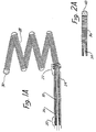
- Figure 1 is an enlarged side view of a first embodiment of the distal end of a prior art wire and tip shown in partial cross-sectional view.
- a conventional Teflon laminated or similarly insulated stainless steel wire 10 is disposed within a protective microcatheter (not shown).
- Stainless steel wire 10 is approximately 0.010-0.020 inch (0.254-0.508 mm) in diameter.
- wire 10 is tapered at its distal end to form a conical section 12 which joins a section 14 of reduced diameter which extends longitudinally along a length 16 of wire 10. Section 16 then narrows gradually down to a thin threadlike portion 18 beginning at a first bonding location 20 and ending at a second bonding location 22.
- the stainless steel wire 10 comprised of that portion disposed within the microcatheter body, tapered section 12, reduced diameter section 16 and threadlike section 18, is collectively referred to as a core wire which typically is 50 - 300 cm. in length.
- the portion of the core wire extending from tapered section 12 to second bonding location 22 is collectively referred to as the grinding length and may typically be between 20 and 50 cm. in length.
- Reduced diameter portion 14 and at least part of sections 12 and first bonding location 20 may be covered with an insulating Teflon (a registered trade mark) laminate 24 which encapsulates the underlying portion of wire 10 to prevent contact with the blood.
- Teflon a registered trade mark
- a stainless steel coil 26 is soldered to the proximate end of threadlike portion 18 of wire 10 at first bonding location 20.
- Stainless steel coil 26 is typically 3 to 10 cm. in length and like wire 10 has a diameter typically between 0.010 to 0.020 inch (0.254-0.508 mm).
- the distal end of stainless steel coil 26 is soldered to the distal end of threadlike portion 18 of wire 10 and to the proximal end of a platinum secondary coil 28 at second bonding location 22.
- Secondary coil 28 itself forms a spiral or helix typically between 2 to 10 mm. in diameter.
- the helical envelope formed by secondary coil 28 may be cylindrical or conical.
- secondary coil 28 is between approximately 0.010 and 0.020 inch (0.254-0508 mm) in diameter.
- the diameter of the wire itself forming stainless steel coil 26 and coil 28 is approximately between 0.001 - 0.005 inch.
- the distal end of secondary coil 28 is provided with a platinum soldered tip 30 to form a rounded and smooth termination to avoid puncturing the aneurysm or tearing tissue.
- secondary coil 28 Although prebiased to form a cylindrical or conical envelope, secondary coil 28 is extremely soft and its overall shape is easily deformed. When inserted within the microcatheter (not shown), secondary coil 28 is easily straightened to lie axially within the microcatheter. Once disposed out of the tip of the microcatheter, secondary coil 28 forms the shape shown in Figure 1 and may similarly be loosely deformed to the interior shape of the aneurysm.
- a direct current is applied to wire 10 from a voltage source exterior to the body.
- the positive charge on secondary coil 28 within the cavity of the aneurysm causes a thrombus to form within the aneurysm by electrothrombosis.
- Detachment of the tip occurs either: (1 ) by continued application of current for a predetermined time when the portion 18 is exposed to blood; or (2) by movement of the wire to expose portion 18 to blood followed by continued current application for a predetermined time.
- both threadlike portion and stainless steel coil 26 kill be completely disintegrated at least at one point, thereby allowing wire 10 to be withdrawn from the vascular space while leaving secondary coil 28 embedded within the thrombus formed within the aneurysm.
- FIG. 2 illustrates in enlarged partially cross-sectional view a second prior art embodiment.
- Stainless steel core 32 terminates in a conical distal portion 34.
- Stainless steel coil 36 shown in cross-sectional view, is soldered to distal portion 34 of wire 32 at bonding location 38.
- the opposing end of the stainless steel coil 36 is provided with a soldered, rounded platinum tip 40.
- stainless steel core wire 32 is approximately 0.25 mm (0.010 inch) in diameter with the length of stainless steel coil 36 being approximately 8 cm. with the longitudinal length of platinum tip 40 being between 3 and 10 mm.
- the total length of wire 32 from tip 40 to the proximate end is approximately 150 cm.
- the embodiment of Figure 2 is utilized in exactly the same manner as described above in connection with Figure 1 to form a thrombic mass within an aneurysm or other vascular cavity.
- the embodiment of Figure 2 is distinguished from that shown in Figure 1 by the absence of the extension of stainless core 32 through coil 36 to tip 40. In the ease of the embodiment of Figure 2 no inner core or reinforcement is provided within stainless steel coil 36.
- Threadlike portion 18 is provided in the embodiment of Figure 1 to allow increased tensile strength of the wire. However, a degree of flexibility of the wire is sacrificed by the inclusion even of threadlike tip 18, so that the embodiment of Figure 2 provides a more flexible tip, at least for that portion of the micro-guidewire constituting the stainless steel coil 36.
- Thinned and threadlike portion guidewires disposed concentrically within coiled portions are well known and are shown in Antoshkiw , "Disposable Guidewire", U.S. Patent 3,789,841 (1974); Sepetka et al ., "Guidewire Device", U.S. Patent 4,832,047 (1989); Engelson , "Catheter Guidewire”, U.S. Patent 4,884,579 (1989); Samson et al ., “Guidewire for Catheters", U.S. Patent 4,538,622 (1985); and Samson et al ., “Catheter Guidewire with Short Spring Tip and Method of Using the Same", U.S. Patent 4,554,929 (1985).
- Figure 3 shows an enlarged side view of a wire, generally denoted by reference numeral 42, disposed within a microcatheter 44 shown in cross-sectional view.
- a stainless steel coil 46 is soldered to a conical portion 48 of wire 22 at a first bonding location 50.
- a thin threadlike extension 52 is then longitudinally disposed within stainless steel coil 46 to a second bonding location 54 where stainless steel wire 46 and threadlike portion 52 are soldered to a soft platinum coil 56.
- Platinum coil 56 is not prebiased, nor does it contain any internal reinforcement, but is a free and open coil similar in that respect to stainless steel coil 36 of the embodiment of Figure 2.
- platinum coil 56 is particularly distinguished by its length of approximately 1 to 50 cm. and by its flexibility.
- the platinum or platinum alloy used is particularly pliable and to diameter of the wire used to form platinum coil 56 is approximately 0.025-0.13mm (0.001 - 0.005 inch) in diameter.
- the distal end of platinum coil 56 is provided with a smooth and rounded platinum tip 58 similar in that respect to tips 30 and 40 of Figures 1 and 2, respectively.
- microcatheter 44 When coil 56 is disposed within microcatheter 44, it lies along the longitudinal lumen 60 defined by microcatheter 44.
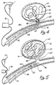
- the distal end 62 of microcatheter 60 is then placed into the neck of the aneurysm and the wire 42 is advanced, thereby feeding tip 58 of platinum coil 56 into aneurysm 64 until bonding location 50 resides in the neck of the aneurysm as best depicted in the diagrammatic cross-sectional view of Figure 4.
- Figure 4 illustrates the insertion of the embodiment of Figure 3 within a vessel 66 with distal tip of microcatheter 44 positioned near neck 68 of aneurysm 64.
- Coil 56 is fed into aneurysm 64 until at least a portion of stainless steel coil 46 is exposed beyond the distal tip 62 of microcatheter 44.
- a positive electric current of approximately 0.01 to 2 milliamps at 0.1 - 6 volts is applied to wire 42 to form the thrombus. Typically a thrombus will form within three to five minutes.
- the negative pole 72 of voltage source 70 is typically placed over and in contact with the skin.
- tip 58 and coil 56 are detached from wire 42 by electrolytic disintegration of at least one portion of stainless steel coil 46. In the illustrated embodiment this is accomplished by continued application of current until the total time of current application is almost approximately four minutes.
- At least one portion of stainless steel coil 46 will be completely dissolved through by electrolytic action within 3 to 10 minutes, usually about 4 minutes.
- wire 42, microcatheter 44 and the remaining portion of coil 46 still attached to wire 42 are removed from vessel 66, leaving aneurysm 64 completely occluded as diagrammatically depicted in Figure 5 by thrombus 74. It will be appreciated that the time of disintegration may be varied by altering the dimensions of the portions of the wire and/or the current.
- the process is practiced under fluoroscopic control with local anesthesia at the groin.
- a transfemoral microcatheter is utilized to treat the cerebral aneurysm.
- the platinum is not affected by electrolysis and the remaining portions of the microcatheter are insulated either by a Teflon (a registered trade mark) lamination directly on wire 42 and/or by microcatheter 44. Only the exposed portion of the wire 46 is affected by the electrolysis.
- thrombus 74 continues to form even after detachment from wire 42. It is believed that a positive charge is retained on or near coil 56 which therefore continues to attract platelets, white blood cells, red blood cells and fibrinogen within aneurysm 64.
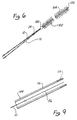
- Wire 10 has a tapering end portion 14 covered with a Teflon (a registered trade mark) laminate 24 similar to that described in connection with the embodiment of Figure 1.
- Wire 10 is attached by means of a mechanical coupling 100 to a platinum coil 102 which has a plurality of filaments or fine hairs 104 extending therefrom.
- hairs 104 have a length as may be determined from the size of the vascular cavity in which coil 102 is to be used. For example, in a small vessel hair lengths of up to 1 mm are contemplated.
- An example of polyester filaments or hairs attached to a coil which was not used in electrothrombosis may be seen in US-A-5 226 911, entitled Vasoocclusion Coil with Attached Fiberous Elements.
- Coil 102 has sufficient length and flexibility that it can be inserted or coiled loosely into the vascular cavity.
- the length of coil 102 need not be so long that the coil itself is capable of being multiply folded on itself and fill or substantially fill the vascular cavity.
- Hairs 104 extending from coil 102 serve to substantially pack, fill or at least impede blood flow or access in the vascular cavity.
- Hairs 104 which are generally inclined backwardly away from extreme tip 106 when delivered, are thus easily able to slide forward with little friction through restrictions in the vessels and aneurysm. Additionally, hairs 104 do not have sufficient length, strength or sharpness to provide any substantial risk or potential for a puncture of the thin vascular wall.
- the plurality of hairs 104 when coiled within the vascular cavity, provide an extremely large surface for attachment of blood constituents to encourage and enhance the formation of a mechanical occlusion within the vascular opening.
- coil 102 is mechanically coupled to thin tapered portion 104 of wire 10 by means of a small drop of polyester 100.
- Polyester may be substituted for the gold solder of the previously described embodiments in order to reduce concern or risk of toxic reactions in the body.
- Tip portion 104 may also be mechanically separated from wire 10 by means other than electrolysis.
- One method is make the connection between tip 104 and wire 10 by means of a spring loaded mechanical clasp (not shown). The clasps are retained on tip 104 as long as the clasps remain inside of the catheter, but spring open and release tip 104 when extended from the catheter. The catheter and clasps may then be removed from the insertion site.
- This type of mechanical connection is described in US-A-5 304 195, entitled, “Detachable Pusher-Vasoocclusive Coil Assembly with Interlocking Coupling”.
- An alternative nonresilient mechanical ball and clasp capturing mechanism is described in US-A-5 261 916, entitled “Detachable Pusher-Vasoocclusive Coil Assembly with Interlocking Ball and Keyway Coupling”.
- wire 10 and tip portion 104 screw into each other and can be unscrewed from each other by rotation of the catheter or wire with respect to tip 104.
- An extendable sheath (not shown) in the microcatheter is advanced to seize tip 104 to prevent its rotation with wire 10 during the unscrewing process.
- This type of mechanical connection is described in US-A-5 234 437, entitled “Detachable Pusher-Vasoocclusive Coil Assembly with Threaded Couplings”.
- tip 104 may be effected by electrolysis.
- the electrolysing current may be concentrated on the sacrificial stainless steel portion of tip 104 by disposition of an insulative coating on the remaining platinum portion.
- tip 104 may be provided with a polyethylene coating save at least a portion of the stainless steel length. This has the effect of decreasing the time required to electrolytically sufficiently disintegrate the steel portion to allow detachment of the platinum tip, which is an advantageous feature in those cases where a large aneurysm must be treated and a multiple number of coils must be deployed within the aneurysm.
- wire 10 and platinum coil 102 in the embodiment Figure 6 or wire 10 and platinum coil 28, 36 and 56 in the embodiments of Figures 1-5 are radiopaque, there is still some difficulty when manipulating the device under fluoroscopy to be able to determine the exact position or movement of the probe relative to the aneurysm. This is particularly true when a large number of coils are deployed and one coil then radiographically hides another.
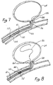
- Figure 7 illustrates an improvement of, for example, the embodiment of Figures 4 and 5.
- Microcatheter 144 is positioned so that its distal end 162 within vessel 66 is positioned at the opening aneurysm 64.
- Microcatheter 144 is provided with radiopaque marker 108 at distal tip 162, a tip marker.
- Radiopaque markers 108 and 110 are, for example, in the form of radiopaque rings made of platinum, approximately 1-3 mm in longitudinal length along the axis of microcatheter 144. Rings 110 and 108 are typically separated by about 3 cm on microcatheter 144.
- wire 10 has a radiopaque marker 112 defined on it such that marker 112 on wire 10 is approximately with aligned with marker 110 on microcatheter 14 when coil 56 is fully deployed into aneurysm 64. Typically, full deployment will place the solder or connection point 54 of the order of 2-3 mm past opening 68 of aneurysm 64.
- Distal marker 108 on microcatheter 144 is used to facilitate the location of the microcatheter tip, which can often he obscured by the coils which have been previously deployed.
- the coils are a varying lengths depending on the application or size of the aneurysm or vascular cavity being treated. Coil lengths of 4-40 cm are common. Therefore, even though the thinness of coil 56 may make it difficult to see under standard fluoroscopy and even though the fineness of wire 10 may similarly be obscured or partly obscured, radiopaque markers 108, 110 and 112 are clearly visible. Manipulation of wire 10 to proximal marker 110 can then easily be observed under conventional fluoroscopy even when there are some loss of resolution or fluoroscopic visual obstruction of the coil.
- FIG. 9 illustrates an alternative embodiment wherein microcatheter 144 is supplied with an end electrode 114 coupled to an electrical conductor 116 disposed along the length of microcatheter 144. Wire 116 is ultimately led back to voltage source 70 so that ring electrode 114 is used as the cathode during electrothrombosis instead of an exterior skin electrode 72.
- the electrical currents and electrical current paths which are set up during the electrothrombosis formation are local to the site of application which allows even smaller currents and voltages to be used to initiate electrothrombosis than in the situation when an exterior skin electrode must be utilized.
- the electrothrombosic current distributions are also better controlled and localized to the site of the thrombus formation The possibility of stray thrombus formations occurring at unwanted sites or uncontrolled and possibly unwanted electrical current patterns being established elsewhere in the brain or body is therefore largely avoided.
- the shape of the tip or distal platinum coil used in combination with the wire according to the invention may be provided with a variety of shapes and envelopes.
- the composition of the micro-guidewire tip may be made of elements other than platinum including stainless steel, beryllium, copper and various alloys of the same with or without platinum.
- the diameter of the wire, various of the wire described above and the stainless steel coil immediately proximal to the detachable tip may be provided with differing diameters or cross sections to vary the times and current magnitudes necessary in order to effectuate electrolytic detachment from the tip.
- the invention may include conventional electronics connected to the proximal end of the wire for determining the exact instant of detachment of the distal tip from the wire.
Abstract
Description
Claims (10)
- A wire (10, 102) for use in combination with a microcatheter to form an occlusion within a vascular cavity, the wire comprising:a core wire (10); anda detachable elongate tip portion (102) coupled to a distal portion of the core wire, the tip portion extending the core wire for a predetermined lineal extent and being adapted to be positioned, in use, in a vascular cavity to form an occlusion in the vascular cavity, whereby endovascular occlusion of the vascular cavity can be performed;characterised in that the detachable elongate tip portion (102) has a plurality of filaments or fine hairs (104) extending therefrom.
- A wire as claimed in claim 1, wherein the filaments or fine hairs (104) are arranged to substantially pack, fill or at least impede blood flow or access in the vascular cavity when the tip portion (102) is disposed therein.
- A wire as claimed in claim 1 or claim 2, wherein the filaments or fine hairs (104) are up to 1 mm in length.
- A wire as claimed in any one of the preceding claims, wherein the filaments or fine hairs (104) are polyester.
- A wire as claimed in any one of the preceding claims, wherein the elongate tip portion is a coil.
- A wire as claimed in claim 5, wherein the coil (102) is a platinum coil.
- A wire as claimed in any one of the preceding claims, wherein the core wire (10) and the detachable elongate tip portion (102) are coupled by polyester (100).
- A wire as claimed in any one of the preceding claims, wherein the elongate tip portion (102) is detachable from the core wire (10) by mechanical means.
- A wire as claimed in claim 8, wherein the elongate tip portion is releasably connected to the core wire (10) by a spring-loaded mechanical clasp.
- A wire as claimed in any one of claims 1 to 7, wherein the elongate tip portion (102) is detachable from the core wire (10) by electrolytic disintegration of part of the wire.
Applications Claiming Priority (3)
| Application Number | Priority Date | Filing Date | Title |
|---|---|---|---|
| US840211 | 1992-02-24 | ||
| US07/840,211 US5354295A (en) | 1990-03-13 | 1992-02-24 | In an endovascular electrolytically detachable wire and tip for the formation of thrombus in arteries, veins, aneurysms, vascular malformations and arteriovenous fistulas |
| EP92922392A EP0629125B1 (en) | 1992-02-24 | 1992-09-30 | Microcatheter system |
Related Parent Applications (2)
| Application Number | Title | Priority Date | Filing Date |
|---|---|---|---|
| EP92922392A Division EP0629125B1 (en) | 1992-02-24 | 1992-09-30 | Microcatheter system |
| EP92922392.3 Division | 1993-09-10 |
Publications (3)
| Publication Number | Publication Date |
|---|---|
| EP0804906A2 EP0804906A2 (en) | 1997-11-05 |
| EP0804906A3 EP0804906A3 (en) | 1997-11-19 |
| EP0804906B1 true EP0804906B1 (en) | 1999-01-07 |
Family
ID=25281739
Family Applications (6)
| Application Number | Title | Priority Date | Filing Date |
|---|---|---|---|
| EP97112838A Expired - Lifetime EP0804906B1 (en) | 1992-02-24 | 1992-09-30 | Endovascular electrolytically detachable wire for thrombus formation |
| EP00104781A Expired - Lifetime EP1005837B2 (en) | 1992-02-24 | 1992-09-30 | Apparatus for occluding a vascular cavity |
| EP03010295A Expired - Lifetime EP1366720B1 (en) | 1992-02-24 | 1992-09-30 | Endovascular electrolytically detachable wire for thrombus formation |
| EP92922392A Expired - Lifetime EP0629125B1 (en) | 1992-02-24 | 1992-09-30 | Microcatheter system |
| EP03007337A Withdrawn EP1323385A3 (en) | 1992-02-24 | 1992-09-30 | Endovascular electrolytically detachable wire for thrombus formation |
| EP97112837A Expired - Lifetime EP0803230B1 (en) | 1992-02-24 | 1992-09-30 | Endovascular electrolytically detachable wire for thrombus formation |
Family Applications After (5)
| Application Number | Title | Priority Date | Filing Date |
|---|---|---|---|
| EP00104781A Expired - Lifetime EP1005837B2 (en) | 1992-02-24 | 1992-09-30 | Apparatus for occluding a vascular cavity |
| EP03010295A Expired - Lifetime EP1366720B1 (en) | 1992-02-24 | 1992-09-30 | Endovascular electrolytically detachable wire for thrombus formation |
| EP92922392A Expired - Lifetime EP0629125B1 (en) | 1992-02-24 | 1992-09-30 | Microcatheter system |
| EP03007337A Withdrawn EP1323385A3 (en) | 1992-02-24 | 1992-09-30 | Endovascular electrolytically detachable wire for thrombus formation |
| EP97112837A Expired - Lifetime EP0803230B1 (en) | 1992-02-24 | 1992-09-30 | Endovascular electrolytically detachable wire for thrombus formation |
Country Status (14)
| Country | Link |
|---|---|
| US (2) | US5354295A (en) |
| EP (6) | EP0804906B1 (en) |
| JP (2) | JP3152399B2 (en) |
| AT (5) | ATE314014T1 (en) |
| AU (1) | AU673502B2 (en) |
| CA (1) | CA2120779C (en) |
| DE (5) | DE69233026T3 (en) |
| DK (2) | DK1005837T4 (en) |
| ES (3) | ES2192501T5 (en) |
| FI (1) | FI941937A (en) |
| GR (1) | GR3035159T3 (en) |
| NO (2) | NO320812B1 (en) |
| PT (2) | PT101162B (en) |
| WO (1) | WO1993016650A1 (en) |
Cited By (3)
| Publication number | Priority date | Publication date | Assignee | Title |
|---|---|---|---|---|
| USRE41029E1 (en) | 1990-03-13 | 2009-12-01 | The Regents Of The University Of California | Endovascular electrolytically detachable wire and tip for the formation of thrombus in arteries, veins, aneurysms, vascular malformations and arteriovenous fistulas |
| USRE42625E1 (en) | 1990-03-13 | 2011-08-16 | The Regents Of The University Of California | Endovascular electrolytically detachable wire and tip for the formation of thrombus in arteries, veins, aneurysms, vascular malformations and arteriovenous fistulas |
| USRE42662E1 (en) | 1990-03-13 | 2011-08-30 | The Regents Of The University Of California | Endovascular electrolytically detachable wire and tip for the formation of thrombus in arteries, veins, aneurysms, vascular malformations and arteriovenous fistulas |
Families Citing this family (442)
| Publication number | Priority date | Publication date | Assignee | Title |
|---|---|---|---|---|
| US5976131A (en) * | 1990-03-13 | 1999-11-02 | The Regents Of The University At California | Detachable endovascular occlusion device activated by alternating electric current |
| US5851206A (en) * | 1990-03-13 | 1998-12-22 | The Regents Of The University Of California | Method and apparatus for endovascular thermal thrombosis and thermal cancer treatment |
| US5569245A (en) * | 1990-03-13 | 1996-10-29 | The Regents Of The University Of California | Detachable endovascular occlusion device activated by alternating electric current |
| US5122136A (en) * | 1990-03-13 | 1992-06-16 | The Regents Of The University Of California | Endovascular electrolytically detachable guidewire tip for the electroformation of thrombus in arteries, veins, aneurysms, vascular malformations and arteriovenous fistulas |
| US5354295A (en) † | 1990-03-13 | 1994-10-11 | Target Therapeutics, Inc. | In an endovascular electrolytically detachable wire and tip for the formation of thrombus in arteries, veins, aneurysms, vascular malformations and arteriovenous fistulas |
| US6425893B1 (en) * | 1990-03-13 | 2002-07-30 | The Regents Of The University Of California | Method and apparatus for fast electrolytic detachment of an implant |
| DE4104702C2 (en) * | 1991-02-15 | 1996-01-18 | Malte Neuss | Implants for organ pathways in spiral form |
| US5382259A (en) * | 1992-10-26 | 1995-01-17 | Target Therapeutics, Inc. | Vasoocclusion coil with attached tubular woven or braided fibrous covering |
| US5690666A (en) * | 1992-11-18 | 1997-11-25 | Target Therapeutics, Inc. | Ultrasoft embolism coils and process for using them |
| US5645082A (en) * | 1993-01-29 | 1997-07-08 | Cardima, Inc. | Intravascular method and system for treating arrhythmia |
| US5800453A (en) * | 1993-04-19 | 1998-09-01 | Target Therapeutics, Inc. | Detachable embolic coil assembly using interlocking hooks and slots |
| US5573547A (en) * | 1993-10-19 | 1996-11-12 | Leveen; Harry H. | Brush fixation method for attachment of tissues and occlusion of blood vessels |
| US5624449A (en) * | 1993-11-03 | 1997-04-29 | Target Therapeutics | Electrolytically severable joint for endovascular embolic devices |
| US5423829A (en) * | 1993-11-03 | 1995-06-13 | Target Therapeutics, Inc. | Electrolytically severable joint for endovascular embolic devices |
| FR2712797B1 (en) * | 1993-11-26 | 1996-03-01 | Balt Extrusion | Vascular occlusion system. |
| EP0740533A4 (en) * | 1994-01-18 | 1998-01-14 | Endovascular Inc | Apparatus and method for venous ligation |
| ATE295127T1 (en) * | 1994-03-03 | 2005-05-15 | Boston Scient Ltd | DEVICE FOR DETECTING THE DIVISION OF A VASS OCCLUSION DEVICE |
| US6117157A (en) * | 1994-03-18 | 2000-09-12 | Cook Incorporated | Helical embolization coil |
| DE29500381U1 (en) * | 1994-08-24 | 1995-07-20 | Schneidt Bernhard Ing Grad | Device for closing a duct, in particular the ductus arteriosus |
| US5814062A (en) | 1994-12-22 | 1998-09-29 | Target Therapeutics, Inc. | Implant delivery assembly with expandable coupling/decoupling mechanism |
| US5578074A (en) * | 1994-12-22 | 1996-11-26 | Target Therapeutics, Inc. | Implant delivery method and assembly |
| IL116561A0 (en) * | 1994-12-30 | 1996-03-31 | Target Therapeutics Inc | Severable joint for detachable devices placed within the body |
| US5702421A (en) * | 1995-01-11 | 1997-12-30 | Schneidt; Bernhard | Closure device for closing a vascular opening, such as patent ductus arteriosus |
| CA2207667A1 (en) * | 1995-01-27 | 1996-08-01 | Scimed Life Systems, Inc. | Embolizing system |
| US6638291B1 (en) | 1995-04-20 | 2003-10-28 | Micrus Corporation | Three dimensional, low friction vasoocclusive coil, and method of manufacture |
| US5645558A (en) * | 1995-04-20 | 1997-07-08 | Medical University Of South Carolina | Anatomically shaped vasoocclusive device and method of making the same |
| US6171326B1 (en) | 1998-08-27 | 2001-01-09 | Micrus Corporation | Three dimensional, low friction vasoocclusive coil, and method of manufacture |
| US5911731A (en) * | 1995-04-20 | 1999-06-15 | Target Therapeutics, Inc. | Anatomically shaped vasoocclusive devices |
| US8790363B2 (en) | 1995-04-20 | 2014-07-29 | DePuy Synthes Products, LLC | Three dimensional, low friction vasoocclusive coil, and method of manufacture |
| WO1996033763A2 (en) * | 1995-04-28 | 1996-10-31 | Target Therapeutics, Inc. | High performance braided catheter |
| US5639277A (en) * | 1995-04-28 | 1997-06-17 | Target Therapeutics, Inc. | Embolic coils with offset helical and twisted helical shapes |
| US6824553B1 (en) | 1995-04-28 | 2004-11-30 | Target Therapeutics, Inc. | High performance braided catheter |
| US5702373A (en) * | 1995-08-31 | 1997-12-30 | Target Therapeutics, Inc. | Composite super-elastic alloy braid reinforced catheter |
| US6143007A (en) * | 1995-04-28 | 2000-11-07 | Target Therapeutics, Inc. | Method for making an occlusive device |
| US6059779A (en) * | 1995-04-28 | 2000-05-09 | Target Therapeutics, Inc. | Delivery catheter for electrolytically detachable implant |
| JP3007022B2 (en) * | 1995-05-19 | 2000-02-07 | 株式会社カネカメディックス | High frequency power supply for heating |
| US5766160A (en) * | 1995-06-06 | 1998-06-16 | Target Therapeutics, Inc. | Variable stiffness coils |
| NO962336L (en) * | 1995-06-06 | 1996-12-09 | Target Therapeutics Inc | Vaso-occlusive spiral |
| US5624461A (en) * | 1995-06-06 | 1997-04-29 | Target Therapeutics, Inc. | Three dimensional in-filling vaso-occlusive coils |
| US6176240B1 (en) | 1995-06-07 | 2001-01-23 | Conceptus, Inc. | Contraceptive transcervical fallopian tube occlusion devices and their delivery |
| US20110077672A1 (en) * | 1995-06-07 | 2011-03-31 | Fleischman Sidney D | Devices For Installing Stasis Reducing Means In Body Tissue |
| US6132438A (en) * | 1995-06-07 | 2000-10-17 | Ep Technologies, Inc. | Devices for installing stasis reducing means in body tissue |
| US6705323B1 (en) | 1995-06-07 | 2004-03-16 | Conceptus, Inc. | Contraceptive transcervical fallopian tube occlusion devices and methods |
| CN1095641C (en) | 1995-06-23 | 2002-12-11 | 盖拉斯医疗有限公司 | Electrosurgical instrument |
| US6015406A (en) * | 1996-01-09 | 2000-01-18 | Gyrus Medical Limited | Electrosurgical instrument |
| US6293942B1 (en) | 1995-06-23 | 2001-09-25 | Gyrus Medical Limited | Electrosurgical generator method |
| US6780180B1 (en) | 1995-06-23 | 2004-08-24 | Gyrus Medical Limited | Electrosurgical instrument |
| EP1050278A1 (en) | 1995-06-23 | 2000-11-08 | Gyrus Medical Limited | An electrosurgical instrument |
| WO1997001368A1 (en) * | 1995-06-26 | 1997-01-16 | Trimedyne, Inc. | Therapeutic appliance releasing device |
| US6013084A (en) | 1995-06-30 | 2000-01-11 | Target Therapeutics, Inc. | Stretch resistant vaso-occlusive coils (II) |
| US5582619A (en) * | 1995-06-30 | 1996-12-10 | Target Therapeutics, Inc. | Stretch resistant vaso-occlusive coils |
| DE69630898T2 (en) * | 1995-06-30 | 2004-08-26 | Boston Scientific Ltd., Saint Michael | Expansion-resistant vaso-occlusive spiral |
| US5853418A (en) * | 1995-06-30 | 1998-12-29 | Target Therapeutics, Inc. | Stretch resistant vaso-occlusive coils (II) |
| US5743905A (en) * | 1995-07-07 | 1998-04-28 | Target Therapeutics, Inc. | Partially insulated occlusion device |
| US6019757A (en) * | 1995-07-07 | 2000-02-01 | Target Therapeutics, Inc. | Endoluminal electro-occlusion detection apparatus and method |
| US5601600A (en) * | 1995-09-08 | 1997-02-11 | Conceptus, Inc. | Endoluminal coil delivery system having a mechanical release mechanism |
| US6287315B1 (en) | 1995-10-30 | 2001-09-11 | World Medical Manufacturing Corporation | Apparatus for delivering an endoluminal prosthesis |
| DE19547617C1 (en) * | 1995-12-20 | 1997-09-18 | Malte Neus | Appliance for inserting and replacing surgical implant |
| US6013076A (en) | 1996-01-09 | 2000-01-11 | Gyrus Medical Limited | Electrosurgical instrument |
| US6090106A (en) | 1996-01-09 | 2000-07-18 | Gyrus Medical Limited | Electrosurgical instrument |
| AU733332B2 (en) * | 1996-02-02 | 2001-05-10 | Transvascular, Inc. | Methods and apparatus for blocking flow through blood vessels |
| US6270495B1 (en) | 1996-02-22 | 2001-08-07 | Radiotherapeutics Corporation | Method and device for enhancing vessel occlusion |
| US5649949A (en) * | 1996-03-14 | 1997-07-22 | Target Therapeutics, Inc. | Variable cross-section conical vasoocclusive coils |
| US6813520B2 (en) | 1996-04-12 | 2004-11-02 | Novacept | Method for ablating and/or coagulating tissue using moisture transport |
| US7604633B2 (en) | 1996-04-12 | 2009-10-20 | Cytyc Corporation | Moisture transport system for contact electrocoagulation |
| US6066139A (en) * | 1996-05-14 | 2000-05-23 | Sherwood Services Ag | Apparatus and method for sterilization and embolization |
| US5868754A (en) * | 1996-06-12 | 1999-02-09 | Target Therapeutics, Inc. | Medical retrieval device |
| US6565561B1 (en) | 1996-06-20 | 2003-05-20 | Cyrus Medical Limited | Electrosurgical instrument |
| GB2314274A (en) | 1996-06-20 | 1997-12-24 | Gyrus Medical Ltd | Electrode construction for an electrosurgical instrument |
| GB9612993D0 (en) | 1996-06-20 | 1996-08-21 | Gyrus Medical Ltd | Electrosurgical instrument |
| US6190402B1 (en) * | 1996-06-21 | 2001-02-20 | Musc Foundation For Research Development | Insitu formable and self-forming intravascular flow modifier (IFM) and IFM assembly for deployment of same |
| US5972019A (en) * | 1996-07-25 | 1999-10-26 | Target Therapeutics, Inc. | Mechanical clot treatment device |
| US6066158A (en) * | 1996-07-25 | 2000-05-23 | Target Therapeutics, Inc. | Mechanical clot encasing and removal wire |
| US6096034A (en) * | 1996-07-26 | 2000-08-01 | Target Therapeutics, Inc. | Aneurysm closure device assembly |
| US5980514A (en) | 1996-07-26 | 1999-11-09 | Target Therapeutics, Inc. | Aneurysm closure device assembly |
| US5980519A (en) * | 1996-07-30 | 1999-11-09 | Symbiosis Corporation | Electrocautery probe with variable morphology electrode |
| US5823198A (en) * | 1996-07-31 | 1998-10-20 | Micro Therapeutics, Inc. | Method and apparatus for intravasculer embolization |
| JP3784112B2 (en) * | 1996-08-15 | 2006-06-07 | 株式会社カネカメディックス | Coiled embolic material |
| US5964797A (en) | 1996-08-30 | 1999-10-12 | Target Therapeutics, Inc. | Electrolytically deployable braided vaso-occlusion device |
| US5690667A (en) * | 1996-09-26 | 1997-11-25 | Target Therapeutics | Vasoocclusion coil having a polymer tip |
| US5895391A (en) | 1996-09-27 | 1999-04-20 | Target Therapeutics, Inc. | Ball lock joint and introducer for vaso-occlusive member |
| US20010041900A1 (en) * | 1999-12-21 | 2001-11-15 | Ovion, Inc. | Occluding device and method of use |
| US7073504B2 (en) * | 1996-12-18 | 2006-07-11 | Ams Research Corporation | Contraceptive system and method of use |
| GB9626512D0 (en) | 1996-12-20 | 1997-02-05 | Gyrus Medical Ltd | An improved electrosurgical generator and system |
| US5733329A (en) * | 1996-12-30 | 1998-03-31 | Target Therapeutics, Inc. | Vaso-occlusive coil with conical end |
| US5830230A (en) * | 1997-03-07 | 1998-11-03 | Micro Therapeutics, Inc. | Method of intracranial vascular embolotherapy using self anchoring coils |
| US5906618A (en) * | 1997-03-20 | 1999-05-25 | Vanderbilt University | Microcatheter with auxiliary parachute guide structure |
| US6063070A (en) | 1997-08-05 | 2000-05-16 | Target Therapeutics, Inc. | Detachable aneurysm neck bridge (II) |
| JP4127960B2 (en) | 1997-08-05 | 2008-07-30 | ボストン サイエンティフィック リミテッド | Detachable aneurysm neck bridge |
| US6711436B1 (en) | 1997-08-08 | 2004-03-23 | Duke University | Compositions, apparatus and methods for facilitating surgical procedures |
| US6086577A (en) * | 1997-08-13 | 2000-07-11 | Scimed Life Systems, Inc. | Detachable aneurysm neck bridge (III) |
| US6860893B2 (en) | 1997-08-29 | 2005-03-01 | Boston Scientific Scimed, Inc. | Stable coil designs |
| US6322576B1 (en) | 1997-08-29 | 2001-11-27 | Target Therapeutics, Inc. | Stable coil designs |
| US5984929A (en) * | 1997-08-29 | 1999-11-16 | Target Therapeutics, Inc. | Fast detaching electronically isolated implant |
| US6156061A (en) | 1997-08-29 | 2000-12-05 | Target Therapeutics, Inc. | Fast-detaching electrically insulated implant |
| US6066149A (en) | 1997-09-30 | 2000-05-23 | Target Therapeutics, Inc. | Mechanical clot treatment device with distal filter |
| US6074407A (en) | 1997-10-14 | 2000-06-13 | Target Therapeutics, Inc. | Delivery catheter for occlusive implants |
| US6304769B1 (en) | 1997-10-16 | 2001-10-16 | The Regents Of The University Of California | Magnetically directable remote guidance systems, and methods of use thereof |
| US6511468B1 (en) * | 1997-10-17 | 2003-01-28 | Micro Therapeutics, Inc. | Device and method for controlling injection of liquid embolic composition |
| EP0948935B1 (en) * | 1997-10-30 | 2007-09-05 | Kaneka Medix Corporation | Medical implement for depositing implantable device |
| US6241691B1 (en) | 1997-12-05 | 2001-06-05 | Micrus Corporation | Coated superelastic stent |
| US6159165A (en) | 1997-12-05 | 2000-12-12 | Micrus Corporation | Three dimensional spherical micro-coils manufactured from radiopaque nickel-titanium microstrand |
| US6168570B1 (en) | 1997-12-05 | 2001-01-02 | Micrus Corporation | Micro-strand cable with enhanced radiopacity |
| US6136015A (en) * | 1998-08-25 | 2000-10-24 | Micrus Corporation | Vasoocclusive coil |
| US6036720A (en) * | 1997-12-15 | 2000-03-14 | Target Therapeutics, Inc. | Sheet metal aneurysm neck bridge |
| US6203547B1 (en) | 1997-12-19 | 2001-03-20 | Target Therapeutics, Inc. | Vaso-occlusion apparatus having a manipulable mechanical detachment joint and a method for using the apparatus |
| US6475227B2 (en) | 1997-12-24 | 2002-11-05 | Scimed Life Systems, Inc. | Vaso-occlusion apparatus having a mechanically expandable detachment joint and a method for using the apparatus |
| US5873907A (en) * | 1998-01-27 | 1999-02-23 | Endotex Interventional Systems, Inc. | Electrolytic stent delivery system and methods of use |
| US6346091B1 (en) * | 1998-02-13 | 2002-02-12 | Stephen C. Jacobsen | Detachable coil for aneurysm therapy |
| US6022369A (en) | 1998-02-13 | 2000-02-08 | Precision Vascular Systems, Inc. | Wire device with detachable end |
| US5941888A (en) | 1998-02-18 | 1999-08-24 | Target Therapeutics, Inc. | Vaso-occlusive member assembly with multiple detaching points |
| US6077260A (en) | 1998-02-19 | 2000-06-20 | Target Therapeutics, Inc. | Assembly containing an electrolytically severable joint for endovascular embolic devices |
| GB9807303D0 (en) | 1998-04-03 | 1998-06-03 | Gyrus Medical Ltd | An electrode assembly for an electrosurgical instrument |
| US6168615B1 (en) | 1998-05-04 | 2001-01-02 | Micrus Corporation | Method and apparatus for occlusion and reinforcement of aneurysms |
| US8551082B2 (en) | 1998-05-08 | 2013-10-08 | Cytyc Surgical Products | Radio-frequency generator for powering an ablation device |
| US6293960B1 (en) * | 1998-05-22 | 2001-09-25 | Micrus Corporation | Catheter with shape memory polymer distal tip for deployment of therapeutic devices |
| JP4741728B2 (en) | 1998-06-04 | 2011-08-10 | ニューヨーク・ユニバーシティ | Intravascular thin film device and stroke treatment |
| US6139564A (en) * | 1998-06-16 | 2000-10-31 | Target Therapeutics Inc. | Minimally occlusive flow disruptor stent for bridging aneurysm necks |
| US5980550A (en) * | 1998-06-18 | 1999-11-09 | Target Therapeutics, Inc. | Water-soluble coating for bioactive vasoocclusive devices |
| US5935148A (en) * | 1998-06-24 | 1999-08-10 | Target Therapeutics, Inc. | Detachable, varying flexibility, aneurysm neck bridge |
| US6656218B1 (en) | 1998-07-24 | 2003-12-02 | Micrus Corporation | Intravascular flow modifier and reinforcement device |
| US6165194A (en) | 1998-07-24 | 2000-12-26 | Micrus Corporation | Intravascular flow modifier and reinforcement device |
| US6149664A (en) * | 1998-08-27 | 2000-11-21 | Micrus Corporation | Shape memory pusher introducer for vasoocclusive devices |
| US6224610B1 (en) | 1998-08-31 | 2001-05-01 | Micrus Corporation | Shape memory polymer intravascular delivery system with heat transfer medium |
| US6478773B1 (en) | 1998-12-21 | 2002-11-12 | Micrus Corporation | Apparatus for deployment of micro-coil using a catheter |
| US6296622B1 (en) | 1998-12-21 | 2001-10-02 | Micrus Corporation | Endoluminal device delivery system using axially recovering shape memory material |
| US6500149B2 (en) | 1998-08-31 | 2002-12-31 | Deepak Gandhi | Apparatus for deployment of micro-coil using a catheter |
| WO2000013593A1 (en) | 1998-09-04 | 2000-03-16 | Boston Scientific Limited (Incorporated In Ireland) | Detachable aneurysm neck closure patch |
| US7410482B2 (en) | 1998-09-04 | 2008-08-12 | Boston Scientific-Scimed, Inc. | Detachable aneurysm neck bridge |
| US6277126B1 (en) * | 1998-10-05 | 2001-08-21 | Cordis Neurovascular Inc. | Heated vascular occlusion coil development system |
| US6277125B1 (en) | 1998-10-05 | 2001-08-21 | Cordis Neurovascular, Inc. | Embolic coil deployment system with retaining jaws |
| WO2000021443A1 (en) * | 1998-10-09 | 2000-04-20 | Cook Incorporated | Vasoocclusion coil device having a core therein |
| US8016852B2 (en) * | 1998-11-10 | 2011-09-13 | Stryker Corporation | Bioactive components for incorporation with vaso-occlusive members |
| US6723112B2 (en) | 1998-11-10 | 2004-04-20 | Scimed Life Systems, Inc. | Bioactive three loop coil |
| US6569179B2 (en) | 1998-11-10 | 2003-05-27 | Scimed Life Systems, Inc. | Bioactive three loop coil |
| US6187024B1 (en) | 1998-11-10 | 2001-02-13 | Target Therapeutics, Inc. | Bioactive coating for vaso-occlusive devices |
| US6383204B1 (en) | 1998-12-15 | 2002-05-07 | Micrus Corporation | Variable stiffness coil for vasoocclusive devices |
| US6102932A (en) | 1998-12-15 | 2000-08-15 | Micrus Corporation | Intravascular device push wire delivery system |
| EP1010396B1 (en) | 1998-12-16 | 2003-05-07 | Arthesys | Catheter system for release of embolization coils by hydraulic pressure |
| US6835185B2 (en) | 1998-12-21 | 2004-12-28 | Micrus Corporation | Intravascular device deployment mechanism incorporating mechanical detachment |
| US6165140A (en) | 1998-12-28 | 2000-12-26 | Micrus Corporation | Composite guidewire |
| US6221066B1 (en) | 1999-03-09 | 2001-04-24 | Micrus Corporation | Shape memory segmented detachable coil |
| US6887235B2 (en) | 1999-03-24 | 2005-05-03 | Micrus Corporation | Variable stiffness heating catheter |
| US6352531B1 (en) | 1999-03-24 | 2002-03-05 | Micrus Corporation | Variable stiffness optical fiber shaft |
| US6267776B1 (en) | 1999-05-03 | 2001-07-31 | O'connell Paul T. | Vena cava filter and method for treating pulmonary embolism |
| US6648854B1 (en) | 1999-05-14 | 2003-11-18 | Scimed Life Systems, Inc. | Single lumen balloon-tipped micro catheter with reinforced shaft |
| US6458137B1 (en) | 1999-05-26 | 2002-10-01 | Cook Incorporated | Assembly for positioning an embolization coil in the vascular system and a method of introducing a detachable embolization coil |
| EP1867300A3 (en) | 1999-06-02 | 2008-02-27 | Sethel Interventional, Inc. | Intracorporeal occlusive device |
| US6280457B1 (en) * | 1999-06-04 | 2001-08-28 | Scimed Life Systems, Inc. | Polymer covered vaso-occlusive devices and methods of producing such devices |
| WO2001003666A2 (en) * | 1999-07-12 | 2001-01-18 | Scimed Life Systems, Inc. | Liquid based vaso-occlusive compositions |
| US6663607B2 (en) | 1999-07-12 | 2003-12-16 | Scimed Life Systems, Inc. | Bioactive aneurysm closure device assembly and kit |
| US6309367B1 (en) | 1999-07-23 | 2001-10-30 | Neurovasx, Inc. | Aneurysm shield |
| US6312421B1 (en) | 1999-07-23 | 2001-11-06 | Neurovasx, Inc. | Aneurysm embolization material and device |
| US6689120B1 (en) | 1999-08-06 | 2004-02-10 | Boston Scientific Scimed, Inc. | Reduced profile delivery system |
| US6763833B1 (en) | 1999-08-23 | 2004-07-20 | Conceptus, Inc. | Insertion/deployment catheter system for intrafallopian contraception |
| US6709667B1 (en) | 1999-08-23 | 2004-03-23 | Conceptus, Inc. | Deployment actuation system for intrafallopian contraception |
| US8048104B2 (en) * | 2000-10-30 | 2011-11-01 | Dendron Gmbh | Device for the implantation of occlusion spirals |
| US6342063B1 (en) | 2000-01-26 | 2002-01-29 | Scimed Life Systems, Inc. | Device and method for selectively removing a thrombus filter |
| WO2001054761A2 (en) * | 2000-01-28 | 2001-08-02 | William Cook, Europe Aps | Endovascular medical device with plurality of wires |
| US7740637B2 (en) | 2000-02-09 | 2010-06-22 | Micrus Endovascular Corporation | Apparatus and method for deployment of a therapeutic device using a catheter |
| US6397850B1 (en) | 2000-02-09 | 2002-06-04 | Scimed Life Systems Inc | Dual-mode apparatus and method for detection of embolic device detachment |
| EP1142535B1 (en) | 2000-04-07 | 2012-10-03 | Collagen Matrix, Inc. | Embolization device |
| EP1307147B1 (en) | 2000-08-11 | 2010-10-06 | Boston Scientific Scimed, Inc. | Variable softness vaso-occlusive coils |
| US6544275B1 (en) | 2000-08-11 | 2003-04-08 | Scimed Life Systems, Inc. | Vaso-occlusive coils with selectively flattened areas |
| US6855154B2 (en) | 2000-08-11 | 2005-02-15 | University Of Louisville Research Foundation, Inc. | Endovascular aneurysm treatment device and method |
| US6579308B1 (en) | 2000-11-28 | 2003-06-17 | Scimed Life Systems, Inc. | Stent devices with detachable distal or proximal wires |
| US6527790B2 (en) | 2000-12-07 | 2003-03-04 | Scimed Life Systems, Inc. | Intravascular balloon catheter for embolic coil delivery |
| US6676657B2 (en) | 2000-12-07 | 2004-01-13 | The United States Of America As Represented By The Department Of Health And Human Services | Endoluminal radiofrequency cauterization system |
| US6540657B2 (en) * | 2000-12-28 | 2003-04-01 | Scimed Life Systems, Inc. | Apparatus and method for internally inducing a magnetic field in an aneurysm to embolize aneurysm with magnetically-controllable substance |
| US6540733B2 (en) | 2000-12-29 | 2003-04-01 | Corazon Technologies, Inc. | Proton generating catheters and methods for their use in enhancing fluid flow through a vascular site occupied by a calcified vascular occlusion |
| US8721625B2 (en) * | 2001-01-26 | 2014-05-13 | Cook Medical Technologies Llc | Endovascular medical device with plurality of wires |
| US7294137B2 (en) * | 2001-03-27 | 2007-11-13 | Boston Scientific Scimed | Device for multi-modal treatment of vascular lesions |
| US6602269B2 (en) | 2001-03-30 | 2003-08-05 | Scimed Life Systems | Embolic devices capable of in-situ reinforcement |
| WO2002089676A2 (en) * | 2001-05-04 | 2002-11-14 | Concentric Medical | Hydrogel filament vaso-occlusive device |
| EP1392182A1 (en) * | 2001-05-04 | 2004-03-03 | Concentric Medical | Hydrogel vaso-occlusive device |
| US6716238B2 (en) | 2001-05-10 | 2004-04-06 | Scimed Life Systems, Inc. | Stent with detachable tethers and method of using same |
| US6921410B2 (en) * | 2001-05-29 | 2005-07-26 | Scimed Life Systems, Inc. | Injection molded vaso-occlusive elements |
| US6585754B2 (en) | 2001-05-29 | 2003-07-01 | Scimed Life Systems, Inc. | Absorbable implantable vaso-occlusive member |
| US6953468B2 (en) * | 2001-06-13 | 2005-10-11 | Cordis Neurovascular, Inc. | Occluding vasculature of a patient using embolic coil with improved platelet adhesion |
| US6673106B2 (en) * | 2001-06-14 | 2004-01-06 | Cordis Neurovascular, Inc. | Intravascular stent device |
| US8252040B2 (en) | 2001-07-20 | 2012-08-28 | Microvention, Inc. | Aneurysm treatment device and method of use |
| US6878151B2 (en) | 2001-09-27 | 2005-04-12 | Scimed Life Systems, Inc. | Medical retrieval device |
| US20030093111A1 (en) * | 2001-10-26 | 2003-05-15 | Concentric Medical | Device for vaso-occlusion and interventional therapy |
| US7219799B2 (en) * | 2002-12-31 | 2007-05-22 | Possis Medical, Inc. | Packaging system with oxygen sensor |
| US6953473B2 (en) * | 2001-12-20 | 2005-10-11 | Boston Scientific Scimed, Inc. | Detachable device with electrically responsive element |
| US7887573B2 (en) * | 2002-02-22 | 2011-02-15 | Boston Scientific Scimed, Inc. | Method and apparatus for deployment of an endoluminal device |
| US7235095B2 (en) * | 2002-02-22 | 2007-06-26 | Scimed Life Systems, Inc. | Method and system for deploying multi-part endoluminal devices |
| US7004964B2 (en) * | 2002-02-22 | 2006-02-28 | Scimed Life Systems, Inc. | Apparatus and method for deployment of an endoluminal device |
| US20030195609A1 (en) * | 2002-04-10 | 2003-10-16 | Scimed Life Systems, Inc. | Hybrid stent |
| US20030195553A1 (en) * | 2002-04-12 | 2003-10-16 | Scimed Life Systems, Inc. | System and method for retaining vaso-occlusive devices within an aneurysm |
| US7195648B2 (en) * | 2002-05-16 | 2007-03-27 | Cordis Neurovascular, Inc. | Intravascular stent device |
| US7060083B2 (en) * | 2002-05-20 | 2006-06-13 | Boston Scientific Scimed, Inc. | Foldable vaso-occlusive member |
| US7166122B2 (en) * | 2002-06-27 | 2007-01-23 | Boston Scientific Scimed, Inc. | Anchor assemblies in stretch-resistant vaso-occlusive coils |
| DE10233085B4 (en) | 2002-07-19 | 2014-02-20 | Dendron Gmbh | Stent with guide wire |
| US8425549B2 (en) | 2002-07-23 | 2013-04-23 | Reverse Medical Corporation | Systems and methods for removing obstructive matter from body lumens and treating vascular defects |
| US7608058B2 (en) * | 2002-07-23 | 2009-10-27 | Micrus Corporation | Stretch resistant therapeutic device |
| US20040044391A1 (en) | 2002-08-29 | 2004-03-04 | Stephen Porter | Device for closure of a vascular defect and method of treating the same |
| US8075585B2 (en) * | 2002-08-29 | 2011-12-13 | Stryker Corporation | Device and method for treatment of a vascular defect |
| US8444666B2 (en) * | 2002-09-12 | 2013-05-21 | Cook Medical Technologies Llc | Retrievable filter |
| US20040098023A1 (en) * | 2002-11-15 | 2004-05-20 | Scimed Life Systems, Inc. | Embolic device made of nanofibers |
| DE10257219B3 (en) * | 2002-12-07 | 2004-06-03 | Frank Dr. Czerwinski | Implantation of occlusion elements comprises transition section with distal end fixed to endovascular guide, and transition enclosed by helical compression spring, and nominal fracture point |
| US20040115164A1 (en) * | 2002-12-17 | 2004-06-17 | Pierce Ryan K. | Soft filament occlusive device delivery system |
| AU2003297534A1 (en) * | 2002-12-24 | 2004-07-22 | Ovion, Inc. | Contraceptive device and delivery system |
| US7300460B2 (en) * | 2002-12-31 | 2007-11-27 | Counter Clockwise, Inc. | Bifurcated guidewire and methods of use |
| US7229454B2 (en) * | 2003-01-07 | 2007-06-12 | Boston Scientific Scimed, Inc. | Occlusive cinching devices and methods of use |
| US20040153025A1 (en) * | 2003-02-03 | 2004-08-05 | Seifert Paul S. | Systems and methods of de-endothelialization |
| US6979330B2 (en) * | 2003-03-13 | 2005-12-27 | Boston Scientific Scimed, Inc. | System for indirectly ablating tissue using implanted electrode devices |
| US8123774B2 (en) * | 2003-03-20 | 2012-02-28 | Boston Scientific Scimed, Inc. | Piezoelectric vascular implant release device |
| US7771463B2 (en) | 2003-03-26 | 2010-08-10 | Ton Dai T | Twist-down implant delivery technologies |
| EP2226040A1 (en) | 2003-03-26 | 2010-09-08 | Cardiomind, Inc. | Stent delivery system with torsionally compressed stent |
| US20040193179A1 (en) | 2003-03-26 | 2004-09-30 | Cardiomind, Inc. | Balloon catheter lumen based stent delivery systems |
| US20050131523A1 (en) * | 2003-04-02 | 2005-06-16 | Mehran Bashiri | Detachable and retrievable stent assembly |
| US7651513B2 (en) * | 2003-04-03 | 2010-01-26 | Boston Scientific Scimed, Inc. | Flexible embolic device delivery system |
| AU2004241111B2 (en) | 2003-05-15 | 2010-05-27 | Dsm Ip Assets B.V | Manufacture and use of implantable reticulated elastomeric matrices |
| US7569626B2 (en) | 2003-06-05 | 2009-08-04 | Dfine, Inc. | Polymer composites for biomedical applications and methods of making |
| US20050021023A1 (en) * | 2003-07-23 | 2005-01-27 | Scimed Life Systems, Inc. | System and method for electrically determining position and detachment of an implantable device |
| US7072495B2 (en) * | 2003-07-30 | 2006-07-04 | Xerox Corporation | System and method for measuring and quantizing document quality |
| US20050061329A1 (en) * | 2003-09-18 | 2005-03-24 | Conceptus, Inc. | Catheter for intrafallopian contraceptive delivery |
| US20050090888A1 (en) * | 2003-10-28 | 2005-04-28 | Hines Richard A. | Pleated stent assembly |
| US20050107867A1 (en) * | 2003-11-17 | 2005-05-19 | Taheri Syde A. | Temporary absorbable venous occlusive stent and superficial vein treatment method |
| US20060241682A1 (en) * | 2003-12-08 | 2006-10-26 | Kurz Daniel R | Intravascular device push wire delivery system |
| US20080109057A1 (en) * | 2003-12-10 | 2008-05-08 | Calabria Marie F | Multiple point detacher system |
| US20070104752A1 (en) * | 2003-12-10 | 2007-05-10 | Lee Jeffrey A | Aneurysm embolization material and device |
| US7763011B2 (en) * | 2003-12-22 | 2010-07-27 | Boston Scientific Scimed, Inc. | Variable density braid stent |
| US20050149109A1 (en) * | 2003-12-23 | 2005-07-07 | Wallace Michael P. | Expanding filler coil |
| US7763077B2 (en) | 2003-12-24 | 2010-07-27 | Biomerix Corporation | Repair of spinal annular defects and annulo-nucleoplasty regeneration |
| DE102004003265A1 (en) * | 2004-01-21 | 2005-08-11 | Dendron Gmbh | Device for the implantation of electrically isolated occlusion coils |
| WO2005074844A1 (en) * | 2004-02-02 | 2005-08-18 | Ams Research Corporation | Contraceptive with permeable and impermeable components |
| WO2005074845A1 (en) * | 2004-02-02 | 2005-08-18 | Ams Research Corporation | Enhancing tissue ingrowth for contraception |
| US7651521B2 (en) | 2004-03-02 | 2010-01-26 | Cardiomind, Inc. | Corewire actuated delivery system with fixed distal stent-carrying extension |
| WO2005110297A2 (en) * | 2004-04-28 | 2005-11-24 | Ams Research Corporation | Endoscopic delivery of medical devices |
| ES2440650T3 (en) * | 2004-05-21 | 2014-01-29 | Covidien Lp | Metallic coils bonded with polymers or synthetic biological or biodegradable fibers for embolization of a body cavity |
| CA2565106C (en) | 2004-05-25 | 2013-11-05 | Chestnut Medical Technologies, Inc. | Flexible vascular occluding device |
| SG175723A1 (en) | 2004-05-25 | 2011-12-29 | Tyco Healthcare | Vascular stenting for aneurysms |
| US9675476B2 (en) | 2004-05-25 | 2017-06-13 | Covidien Lp | Vascular stenting for aneurysms |
| US20050267510A1 (en) * | 2004-05-26 | 2005-12-01 | Nasser Razack | Device for the endovascular treatment of intracranial aneurysms |
| US7749242B2 (en) * | 2004-06-21 | 2010-07-06 | Boston Scientific Scimed, Inc. | Expanding vaso-occlusive device |
| US20050283182A1 (en) * | 2004-06-21 | 2005-12-22 | Concentric Medical, Inc. | Systems and methods for intraluminal delivery of occlusive elements |
| US7296442B2 (en) * | 2004-07-15 | 2007-11-20 | Owens-Brockway Glass Container Inc. | Neck ring cooling |
| US20060025801A1 (en) * | 2004-07-30 | 2006-02-02 | Robert Lulo | Embolic device deployment system with filament release |
| US20060025802A1 (en) * | 2004-07-30 | 2006-02-02 | Sowers William W | Embolic coil delivery system with U-shaped fiber release mechanism |
| US7918872B2 (en) * | 2004-07-30 | 2011-04-05 | Codman & Shurtleff, Inc. | Embolic device delivery system with retractable partially coiled-fiber release |
| JP5087399B2 (en) * | 2004-08-25 | 2012-12-05 | マイクロベンション インコーポレイテッド | Thermal desorption system for implantable devices |
| US7879064B2 (en) * | 2004-09-22 | 2011-02-01 | Micro Therapeutics, Inc. | Medical implant |
| EP1793743B1 (en) | 2004-09-22 | 2009-11-18 | Dendron GmbH | Micro-spiral implantation device |
| US8535345B2 (en) | 2004-10-07 | 2013-09-17 | DePuy Synthes Products, LLC | Vasoocclusive coil with biplex windings to improve mechanical properties |
| US8945024B2 (en) * | 2004-10-29 | 2015-02-03 | Kaneka Medix Corporation | Medical wire |
| JP2008519613A (en) | 2004-11-09 | 2008-06-12 | ボストン サイエンティフィック リミテッド | Vascular occlusion device with composite shaped proximal portion and smaller diameter distal |
| US8771294B2 (en) | 2004-11-26 | 2014-07-08 | Biomerix Corporation | Aneurysm treatment devices and methods |
| US8425550B2 (en) | 2004-12-01 | 2013-04-23 | Boston Scientific Scimed, Inc. | Embolic coils |
| US7731712B2 (en) | 2004-12-20 | 2010-06-08 | Cytyc Corporation | Method and system for transcervical tubal occlusion |
| US7608089B2 (en) * | 2004-12-22 | 2009-10-27 | Boston Scientific Scimed, Inc. | Vaso-occlusive device having pivotable coupling |
| US20060155323A1 (en) | 2005-01-07 | 2006-07-13 | Porter Stephen C | Intra-aneurysm devices |
| US20060155367A1 (en) * | 2005-01-07 | 2006-07-13 | Hines Richard A | Micro-pleated stent assembly |
| US20060155324A1 (en) * | 2005-01-12 | 2006-07-13 | Porter Stephen C | Vaso-occlusive devices with attached polymer structures |
| CN101146484B (en) | 2005-01-25 | 2015-04-08 | 泰科医疗集团有限合伙公司 | Structures for permanent occlusion of a hollow anatomical structure |
| WO2006079992A1 (en) | 2005-01-31 | 2006-08-03 | Koninklijke Philips Electronics N.V. | Method and system for deriving a heart rate without the use of an electrocardiogram in non-3d imaging applications |
| US20060178696A1 (en) * | 2005-02-04 | 2006-08-10 | Porter Stephen C | Macroporous materials for use in aneurysms |
| US20060178697A1 (en) | 2005-02-04 | 2006-08-10 | Carr-Brendel Victoria E | Vaso-occlusive devices including non-biodegradable biomaterials |
| US20060212113A1 (en) * | 2005-02-24 | 2006-09-21 | Shaolian Samuel M | Externally adjustable endovascular graft implant |
| US20060229638A1 (en) * | 2005-03-29 | 2006-10-12 | Abrams Robert M | Articulating retrieval device |
| US8603122B2 (en) | 2005-04-01 | 2013-12-10 | Nexgen Medical Systems, Incorporated | Thrombus removal system and process |
| USRE47376E1 (en) | 2005-04-01 | 2019-05-07 | Nexgen Medical Systems, Incorporated | Thrombus removal system and process |
| US7955344B2 (en) * | 2005-04-01 | 2011-06-07 | Nexgen Medical Systems, Inc. | Thrombus removal system and process |
| US7955345B2 (en) * | 2005-04-01 | 2011-06-07 | Nexgen Medical Systems, Inc. | Thrombus removal system and process |
| EP1868526B1 (en) * | 2005-04-04 | 2018-07-18 | B.Braun Medical SAS | Removable filter head |
| US7674260B2 (en) | 2005-04-28 | 2010-03-09 | Cytyc Corporation | Emergency hemostasis device utilizing energy |
| DE102005019782A1 (en) * | 2005-04-28 | 2006-11-09 | Dendron Gmbh | Device for implantation of occlusion coils with internal securing means |
| US8002789B2 (en) * | 2005-05-31 | 2011-08-23 | Stryker Corporation | Stretch-resistant vaso-occlusive devices with flexible detachment junctions |
| US20060271097A1 (en) * | 2005-05-31 | 2006-11-30 | Kamal Ramzipoor | Electrolytically detachable implantable devices |
| US7708755B2 (en) * | 2005-06-02 | 2010-05-04 | Codman & Shurtleff Inc. | Stretch resistant embolic coil delivery system with combined mechanical and pressure release mechanism |
| US7371252B2 (en) | 2005-06-02 | 2008-05-13 | Cordis Neurovascular, Inc. | Stretch resistant embolic coil delivery system with mechanical release mechanism |
| US7371251B2 (en) * | 2005-06-02 | 2008-05-13 | Cordis Neurovascular, Inc. | Stretch resistant embolic coil delivery system with mechanical release mechanism |
| US7811305B2 (en) * | 2005-06-02 | 2010-10-12 | Codman & Shurtleff, Inc. | Stretch resistant embolic coil delivery system with spring release mechanism |
| US7819892B2 (en) | 2005-06-02 | 2010-10-26 | Codman & Shurtleff, Inc. | Embolic coil delivery system with spring wire release mechanism |
| US7985238B2 (en) * | 2005-06-02 | 2011-07-26 | Codman & Shurtleff, Inc. | Embolic coil delivery system with spring wire release mechanism |
| US7799052B2 (en) * | 2005-06-02 | 2010-09-21 | Codman & Shurtleff, Inc. | Stretch resistant embolic coil delivery system with mechanical release mechanism |
| US7708754B2 (en) | 2005-06-02 | 2010-05-04 | Codman & Shurtleff, Pc | Stretch resistant embolic coil delivery system with mechanical release mechanism |
| US20060276825A1 (en) * | 2005-06-02 | 2006-12-07 | Vladimir Mitelberg | Stretch resistant embolic coil delivery system with mechanical release mechanism |
| US7377932B2 (en) * | 2005-06-02 | 2008-05-27 | Cordis Neurovascular, Inc. | Embolic coil delivery system with mechanical release mechanism |
| US7367987B2 (en) * | 2005-06-02 | 2008-05-06 | Cordis Neurovascular, Inc. | Stretch resistant embolic coil delivery system with mechanical release mechanism |
| US7819891B2 (en) * | 2005-06-02 | 2010-10-26 | Codman & Shurtleff, Inc. | Stretch resistant embolic coil delivery system with spring release mechanism |
| US20060276827A1 (en) * | 2005-06-02 | 2006-12-07 | Vladimir Mitelberg | Stretch resistant embolic coil delivery system with mechanical release mechanism |
| US20060282112A1 (en) * | 2005-06-09 | 2006-12-14 | Stephen Griffin | Method and apparatus for enhanced electrolytic detachment |
| US20070027522A1 (en) * | 2005-06-14 | 2007-02-01 | Chang Jean C | Stent delivery and guidewire systems |
| US9636115B2 (en) * | 2005-06-14 | 2017-05-02 | Stryker Corporation | Vaso-occlusive delivery device with kink resistant, flexible distal end |
| CN102225023B (en) | 2005-07-21 | 2014-04-02 | 泰科医疗集团有限合伙公司 | Systems and methods for treating a hollow anatomical structure |
| JP4243268B2 (en) * | 2005-09-07 | 2009-03-25 | アドバンスド・マスク・インスペクション・テクノロジー株式会社 | Pattern inspection apparatus and pattern inspection method |
| US7670365B2 (en) * | 2005-09-23 | 2010-03-02 | BostonScientific Scimed, Inc. | Secured stent delivery system |
| US20070073334A1 (en) * | 2005-09-29 | 2007-03-29 | Kamal Ramzipoor | Combined electrolytic and mechanical separation background |
| US20070078479A1 (en) * | 2005-10-04 | 2007-04-05 | Boston Scientific Scimed, Inc. | Self-expanding vaso-occlusive devices with regulated expansion |
| US20070078480A1 (en) * | 2005-10-04 | 2007-04-05 | Boston Scientific Scimed, Inc. | Self-expanding biodegradable or water-soluble vaso-occlusive devices |
| US8007509B2 (en) | 2005-10-12 | 2011-08-30 | Boston Scientific Scimed, Inc. | Coil assemblies, components and methods |
| JP2009512515A (en) | 2005-10-19 | 2009-03-26 | パルサー バスキュラー インコーポレイテッド | Methods and systems for clipping within a vessel and repairing intraluminal and tissue defects. |
| US8545530B2 (en) | 2005-10-19 | 2013-10-01 | Pulsar Vascular, Inc. | Implantable aneurysm closure systems and methods |
| US20070100414A1 (en) | 2005-11-02 | 2007-05-03 | Cardiomind, Inc. | Indirect-release electrolytic implant delivery systems |
| EP1959873B1 (en) | 2005-12-13 | 2015-05-20 | Codman & Shurtleff, Inc. | Detachment actuator for use with medical device deployment systems |
| US20070142907A1 (en) * | 2005-12-16 | 2007-06-21 | Micardia Corporation | Adjustable prosthetic valve implant |
| US8152839B2 (en) | 2005-12-19 | 2012-04-10 | Boston Scientific Scimed, Inc. | Embolic coils |
| US8101197B2 (en) | 2005-12-19 | 2012-01-24 | Stryker Corporation | Forming coils |
| US7942894B2 (en) * | 2006-01-31 | 2011-05-17 | Codman & Shurtleff, Inc. | Embolic device delivery system |
| WO2007100556A1 (en) | 2006-02-22 | 2007-09-07 | Ev3 Inc. | Embolic protection systems having radiopaque filter mesh |
| US8251990B2 (en) * | 2006-03-21 | 2012-08-28 | The Cleveland Clinic Foundation | Apparatus and method of performing radiofrequency cauterization and tissue removal |
| US7699884B2 (en) | 2006-03-22 | 2010-04-20 | Cardiomind, Inc. | Method of stenting with minimal diameter guided delivery systems |
| US8235047B2 (en) | 2006-03-30 | 2012-08-07 | Conceptus, Inc. | Methods and devices for deployment into a lumen |
| US20070239193A1 (en) * | 2006-04-05 | 2007-10-11 | Boston Scientific Scimed, Inc. | Stretch-resistant vaso-occlusive devices with distal anchor link |
| US20070239194A1 (en) * | 2006-04-05 | 2007-10-11 | Boston Scientific Scimed, Inc. | Vaso-occlusive devices having expandable fibers |
| US7771451B2 (en) * | 2006-04-05 | 2010-08-10 | Boston Scientific Scimed, Inc. | Method and apparatus for the deployment of vaso-occlusive coils |
| US8998926B2 (en) | 2006-04-06 | 2015-04-07 | DePuy Synthes Products, LLC | Heat detachable coil |
| US8777979B2 (en) | 2006-04-17 | 2014-07-15 | Covidien Lp | System and method for mechanically positioning intravascular implants |
| JP5230602B2 (en) | 2006-04-17 | 2013-07-10 | タイコ ヘルスケア グループ リミテッド パートナーシップ | System and method for mechanically positioning an endovascular implant |
| US9017361B2 (en) | 2006-04-20 | 2015-04-28 | Covidien Lp | Occlusive implant and methods for hollow anatomical structure |
| US8694076B2 (en) * | 2006-07-06 | 2014-04-08 | Boston Scientific Scimed, Inc. | Electroactive polymer radiopaque marker |
| US8366720B2 (en) | 2006-07-31 | 2013-02-05 | Codman & Shurtleff, Inc. | Interventional medical device system having an elongation retarding portion and method of using the same |
| US8062325B2 (en) | 2006-07-31 | 2011-11-22 | Codman & Shurtleff, Inc. | Implantable medical device detachment system and methods of using the same |
| US8486060B2 (en) | 2006-09-18 | 2013-07-16 | Cytyc Corporation | Power ramping during RF ablation |
| US20080269774A1 (en) | 2006-10-26 | 2008-10-30 | Chestnut Medical Technologies, Inc. | Intracorporeal Grasping Device |
| US8414927B2 (en) | 2006-11-03 | 2013-04-09 | Boston Scientific Scimed, Inc. | Cross-linked polymer particles |
| US7846160B2 (en) | 2006-12-21 | 2010-12-07 | Cytyc Corporation | Method and apparatus for sterilization |
| US8845658B2 (en) * | 2007-02-26 | 2014-09-30 | Boston Scientific Scimed, Inc. | Hemostatic clip and delivery system |
| JP5249249B2 (en) | 2007-03-13 | 2013-07-31 | コヴィディエン リミテッド パートナーシップ | Implant including a coil and a stretch resistant member |
| KR20100015521A (en) | 2007-03-13 | 2010-02-12 | 마이크로 테라퓨틱스 인코포레이티드 | An implant, a mandrel, and a method of forming an implant |
| US20100121350A1 (en) * | 2007-04-12 | 2010-05-13 | Greg Mirigian | Instantaneous mechanical detachment mechanism for vaso-occlusive devices |
| US20080287982A1 (en) * | 2007-05-16 | 2008-11-20 | Boston Scientific Scimed, Inc. | Catheters for electrolytically detachable embolic devices |
| EP2444010B1 (en) * | 2007-05-18 | 2017-03-01 | Stryker European Holdings I, LLC | Medical implant detachment systems |
| WO2008147861A1 (en) * | 2007-05-22 | 2008-12-04 | Wilson-Cook Medical Inc. | Embolization coil delivery system |
| JP5436800B2 (en) * | 2007-06-15 | 2014-03-05 | オリンパスメディカルシステムズ株式会社 | Medical instruments |
| US20080319523A1 (en) * | 2007-06-22 | 2008-12-25 | Neuro Vasx, Inc | Aneurysm filler device |
| US20080319522A1 (en) * | 2007-06-22 | 2008-12-25 | Von Lehe Cathleen | Aneurysm filler detacher |
| CN101842061A (en) | 2007-06-25 | 2010-09-22 | 微排放器公司 | Self-expanding prosthesis |
| US20090076417A1 (en) * | 2007-08-08 | 2009-03-19 | Gregory Allen Jones | Glide Clip |
| US8870908B2 (en) | 2007-08-17 | 2014-10-28 | DePuy Synthes Products, LLC | Twisted primary coil for vascular therapy |
| US11337714B2 (en) | 2007-10-17 | 2022-05-24 | Covidien Lp | Restoring blood flow and clot removal during acute ischemic stroke |
| US8088140B2 (en) | 2008-05-19 | 2012-01-03 | Mindframe, Inc. | Blood flow restorative and embolus removal methods |
| US20090138036A1 (en) * | 2007-10-22 | 2009-05-28 | Boston Scientific Scimed, Inc. | Bioabsorbable detachable coil and methods of use and manufacture |
| EP2227163B1 (en) * | 2007-12-03 | 2012-10-10 | Stryker Corporation | Implantable device with electrolytically detachable junction having multiple fine wires |
| CN101896488A (en) * | 2007-12-17 | 2010-11-24 | 马林克罗特公司 | Prepare the mutter method of salt of normorphine |
| CA2710146C (en) | 2007-12-21 | 2017-03-28 | Microvention, Inc. | System and method for locating detachment zone of a detachable implant |
| AU2008345596B2 (en) | 2007-12-21 | 2013-09-05 | Microvention, Inc. | A system and method of detecting implant detachment |
| US8585696B2 (en) * | 2007-12-28 | 2013-11-19 | Boston Scientific Scimed, Inc. | Electrosurgical probe having conductive outer surface to initiate ablation between electrode |
| US20090171339A1 (en) * | 2007-12-28 | 2009-07-02 | Boston Scientific Scimed, Inc. | Electrosurgical probe having current enhancing protrusions |
| JP5623291B2 (en) * | 2008-01-04 | 2014-11-12 | ボストン サイエンティフィック サイムド,インコーポレイテッドBoston Scientific Scimed,Inc. | Separation mechanism for implantable devices |
| BRPI0908500A8 (en) | 2008-02-22 | 2018-10-23 | Micro Therapeutics Inc | imaging methods of restoration of thrombus-occluded blood vessel blood flow, partial or substantial dissolution and thrombus dislocation, self-expanding thrombus removal equipment and integrated removable thrombus mass |
| US20090227976A1 (en) * | 2008-03-05 | 2009-09-10 | Calabria Marie F | Multiple biocompatible polymeric strand aneurysm embolization system and method |
| DK2265193T3 (en) | 2008-04-21 | 2012-01-23 | Nfocus Neuromedical Inc | Embolic devices with braided ball and delivery systems |
| US9675482B2 (en) | 2008-05-13 | 2017-06-13 | Covidien Lp | Braid implant delivery systems |
| US20090306701A1 (en) * | 2008-06-10 | 2009-12-10 | Boston Scientific Scimed, Inc. | Vascular access sheath with integrated return electrode |
| CA2732507A1 (en) | 2008-08-06 | 2010-02-11 | Boston Scientific Scimed, Inc. | Vaso-occlusive devices with textured surfaces |
| CN102202582B (en) | 2008-09-04 | 2014-07-30 | 库拉希尔公司 | Inflatable device for enteric fistula treatment |
| JP5791048B2 (en) | 2008-09-05 | 2015-10-07 | パルサー バスキュラー インコーポレイテッド | System and method for supporting or occluding a physiological opening or cavity |
| US8940011B2 (en) * | 2008-09-09 | 2015-01-27 | Boston Scientific Scimed, Inc. | Composite detachment mechanisms |
| US20100114081A1 (en) * | 2008-11-05 | 2010-05-06 | Spectranetics | Biasing laser catheter: monorail design |
| WO2010065057A1 (en) * | 2008-12-02 | 2010-06-10 | Boston Scientific Scimed, Inc. | Vaso-occlusive devices with attachment assemblies for stretch-resistant members |
| US9545257B2 (en) * | 2008-12-19 | 2017-01-17 | Covidien Lp | Method and apparatus for storage and/or introduction of implant for hollow anatomical structure |
| US8409269B2 (en) | 2009-12-21 | 2013-04-02 | Covidien Lp | Procedures for vascular occlusion |
| US8657870B2 (en) | 2009-06-26 | 2014-02-25 | Biosensors International Group, Ltd. | Implant delivery apparatus and methods with electrolytic release |
| EP3300673A3 (en) | 2009-09-04 | 2018-10-03 | Pulsar Vascular, Inc. | Systems for enclosing an anatomical opening |
| US9113927B2 (en) | 2010-01-29 | 2015-08-25 | Covidien Lp | Apparatus and methods of use for treating blood vessels |
| WO2011119872A1 (en) | 2010-03-24 | 2011-09-29 | Nexgen Medical Systems, Inc. | Thrombus removal system and process |
| WO2011130081A1 (en) | 2010-04-14 | 2011-10-20 | Microvention, Inc. | Implant delivery device |
| CO6380003A1 (en) * | 2010-06-09 | 2012-02-15 | Univ Los Andes | DOUBLE CONE VASCULAR OCLUSION DEVICE OF NITINOL (DCN) FOR CLOSURE OF ARTERIOUS PERSISTENCE DUCTUS |
| US8998947B2 (en) | 2010-09-10 | 2015-04-07 | Medina Medical, Inc. | Devices and methods for the treatment of vascular defects |
| JP6087281B2 (en) | 2010-09-10 | 2017-03-01 | メディナ メディカル,インコーポレイテッド | Device and method for treating vascular abnormalities |
| US9039749B2 (en) | 2010-10-01 | 2015-05-26 | Covidien Lp | Methods and apparatuses for flow restoration and implanting members in the human body |
| EP2648658B1 (en) | 2010-12-06 | 2018-10-24 | Covidien LP | Vascular remodeling device |
| US10010327B2 (en) * | 2010-12-16 | 2018-07-03 | Lawrence Livermore National Security, Llc | Expandable implant and implant system |
| CA2824284C (en) | 2011-01-17 | 2020-10-27 | Novita Therapeutics, Llc | Ballstent device and methods of use |
| US11484318B2 (en) | 2011-01-17 | 2022-11-01 | Artio Medical, Inc. | Expandable body device and method of use |
| US20120245674A1 (en) | 2011-03-25 | 2012-09-27 | Tyco Healthcare Group Lp | Vascular remodeling device |
| US10028745B2 (en) | 2011-03-30 | 2018-07-24 | Noha, Llc | Advanced endovascular clip and method of using same |
| US10398444B2 (en) | 2011-03-30 | 2019-09-03 | Noha, Llc | Advanced endovascular clip and method of using same |
| US20120271409A1 (en) * | 2011-04-25 | 2012-10-25 | Medtronic Vascular, Inc. | Helical Radiopaque Marker |
| WO2012154782A1 (en) | 2011-05-11 | 2012-11-15 | Tyco Healthcare Group Lp | Vascular remodeling device |
| EP2713905B1 (en) | 2011-06-03 | 2022-03-16 | Pulsar Vascular, Inc. | Systems for enclosing an anatomical opening, including shock absorbing aneurysm devices |
| CA2837420C (en) | 2011-06-03 | 2019-07-09 | Pulsar Vascular, Inc. | Aneurysm devices with additional anchoring mechanisms and associated systems and methods |
| US9211116B2 (en) | 2011-06-16 | 2015-12-15 | Curaseal Inc. | Fistula treatment devices and related methods |
| JP6127042B2 (en) | 2011-06-17 | 2017-05-10 | キュラシール インコーポレイテッド | Device and method for fistula treatment |
| US9060886B2 (en) | 2011-09-29 | 2015-06-23 | Covidien Lp | Vascular remodeling device |
| ES2809210T3 (en) | 2011-10-05 | 2021-03-03 | Pulsar Vascular Inc | Systems and devices for wrapping an anatomical opening |
| CN102715930A (en) * | 2011-10-25 | 2012-10-10 | 北京泰杰伟业科技有限公司 | Electric release controller used for embolism spring ring |
| US9072620B2 (en) | 2011-11-04 | 2015-07-07 | Covidien Lp | Protuberant aneurysm bridging device deployment method |
| US9579104B2 (en) | 2011-11-30 | 2017-02-28 | Covidien Lp | Positioning and detaching implants |
| CA3049059C (en) * | 2012-01-17 | 2023-03-07 | Metactive Medical, Inc. | Expandable body device and method of use |
| US9011480B2 (en) | 2012-01-20 | 2015-04-21 | Covidien Lp | Aneurysm treatment coils |
| US9687245B2 (en) | 2012-03-23 | 2017-06-27 | Covidien Lp | Occlusive devices and methods of use |
| WO2013166475A1 (en) | 2012-05-04 | 2013-11-07 | Interventco Llc | Device and method for filling of aneurysm or body cavity |
| WO2013169380A1 (en) | 2012-05-10 | 2013-11-14 | Pulsar Vascular, Inc. | Coil-tipped aneurysm devices |
| US9326774B2 (en) | 2012-08-03 | 2016-05-03 | Covidien Lp | Device for implantation of medical devices |
| JP6176599B2 (en) * | 2012-08-17 | 2017-08-09 | 国立大学法人弘前大学 | Assembly, insert and dilator |
| US9452070B2 (en) | 2012-10-31 | 2016-09-27 | Covidien Lp | Methods and systems for increasing a density of a region of a vascular device |
| US20140135811A1 (en) | 2012-11-13 | 2014-05-15 | Covidien Lp | Occlusive devices |
| US10675039B2 (en) | 2013-03-15 | 2020-06-09 | Embo Medical Limited | Embolisation systems |
| NZ751703A (en) * | 2013-03-15 | 2019-12-20 | Embo Medical Ltd | Embolisation systems |
| EP2967576B1 (en) | 2013-03-15 | 2023-02-15 | Covidien LP | Delivery and detachment mechanisms for vascular implants |
| CN105142545B (en) | 2013-03-15 | 2018-04-06 | 柯惠有限合伙公司 | Locking device |
| US9566071B2 (en) * | 2013-04-11 | 2017-02-14 | Blockade Medical, LLC | Systems and devices for cerebral aneurysm repair |
| JP6055361B2 (en) * | 2013-04-16 | 2016-12-27 | 株式会社カネカ | Counter electrode and electrical detachable in-vivo indwelling device kit |
| EP3041561A4 (en) | 2013-09-03 | 2017-05-10 | Jianlu Ma | Detachment mechanisms for implantable devices |
| US10076399B2 (en) | 2013-09-13 | 2018-09-18 | Covidien Lp | Endovascular device engagement |
| JP6467129B2 (en) * | 2013-10-17 | 2019-02-06 | メディカル・イノベイション株式会社 | catheter |
| US9795400B2 (en) | 2013-11-13 | 2017-10-24 | Covidien Lp | Galvanically assisted attachment of medical devices to thrombus |
| WO2015095806A2 (en) | 2013-12-20 | 2015-06-25 | Microvention, Inc. | Device delivery system |
| US9566072B2 (en) * | 2013-12-27 | 2017-02-14 | Blockade Medical, LLC | Coil system |
| US10278767B2 (en) | 2014-03-27 | 2019-05-07 | Endomedical Concepts, Inc. | Vaporization electrodes and electrosurgical devices equipped therewith |
| EP4151164A1 (en) | 2014-04-11 | 2023-03-22 | Microvention, Inc. | Implant delivery system |
| US9713475B2 (en) | 2014-04-18 | 2017-07-25 | Covidien Lp | Embolic medical devices |
| US9814466B2 (en) | 2014-08-08 | 2017-11-14 | Covidien Lp | Electrolytic and mechanical detachment for implant delivery systems |
| US9808256B2 (en) | 2014-08-08 | 2017-11-07 | Covidien Lp | Electrolytic detachment elements for implant delivery systems |
| WO2016044647A2 (en) | 2014-09-17 | 2016-03-24 | Metactive Medical, Inc. | Expandable body device and method of use |
| US20180271533A1 (en) * | 2014-12-18 | 2018-09-27 | Balt LLC | Vascular Implant System and Processes with Flexible Detachment Zones |
| US10736730B2 (en) | 2015-01-20 | 2020-08-11 | Neurogami Medical, Inc. | Vascular implant |
| WO2016118420A1 (en) | 2015-01-20 | 2016-07-28 | Neurogami Medical, Inc. | Micrograft for the treatment of intracranial aneurysms and method for use |
| US11484319B2 (en) | 2015-01-20 | 2022-11-01 | Neurogami Medical, Inc. | Delivery system for micrograft for treating intracranial aneurysms |
| US10857012B2 (en) | 2015-01-20 | 2020-12-08 | Neurogami Medical, Inc. | Vascular implant |
| US10925611B2 (en) | 2015-01-20 | 2021-02-23 | Neurogami Medical, Inc. | Packaging for surgical implant |
| WO2016154633A1 (en) | 2015-03-26 | 2016-09-29 | Boston Scientific Scimed, Inc. | Systems and methods for vascular occlusion |
| EP3277198B1 (en) | 2015-04-01 | 2023-10-25 | Boston Scientific Scimed, Inc. | Systems for delivery of gel embolics |
| US9717503B2 (en) | 2015-05-11 | 2017-08-01 | Covidien Lp | Electrolytic detachment for implant delivery systems |
| EP3328457B8 (en) | 2015-07-27 | 2021-06-16 | The Texas A&M University System | Medical devices coated with shape memory polymer foams |
| US10314593B2 (en) | 2015-09-23 | 2019-06-11 | Covidien Lp | Occlusive devices |
| US10478194B2 (en) | 2015-09-23 | 2019-11-19 | Covidien Lp | Occlusive devices |
| CN114732470A (en) | 2015-12-30 | 2022-07-12 | 斯瑞克公司 | Embolization device and method of making same |
| WO2017165833A1 (en) | 2016-03-24 | 2017-09-28 | Covidien Lp | Thin wall constructions for vascular flow diversion |
| US10828039B2 (en) | 2016-06-27 | 2020-11-10 | Covidien Lp | Electrolytic detachment for implantable devices |
| US10828037B2 (en) | 2016-06-27 | 2020-11-10 | Covidien Lp | Electrolytic detachment with fluid electrical connection |
| US11051822B2 (en) | 2016-06-28 | 2021-07-06 | Covidien Lp | Implant detachment with thermal activation |
| US10420563B2 (en) | 2016-07-08 | 2019-09-24 | Neurogami Medical, Inc. | Delivery system insertable through body lumen |
| US10478195B2 (en) | 2016-08-04 | 2019-11-19 | Covidien Lp | Devices, systems, and methods for the treatment of vascular defects |
| US10576099B2 (en) | 2016-10-21 | 2020-03-03 | Covidien Lp | Injectable scaffold for treatment of intracranial aneurysms and related technology |
| US10953204B2 (en) | 2017-01-09 | 2021-03-23 | Boston Scientific Scimed, Inc. | Guidewire with tactile feel |
| CN110381889B (en) | 2017-03-14 | 2021-12-31 | 形状记忆医疗公司 | Shape memory polymer foam to seal the space around a valve |
| WO2019036298A1 (en) | 2017-08-17 | 2019-02-21 | Incumedx, Inc. | Flow attenuation device |
| US10675036B2 (en) | 2017-08-22 | 2020-06-09 | Covidien Lp | Devices, systems, and methods for the treatment of vascular defects |
| US11065009B2 (en) | 2018-02-08 | 2021-07-20 | Covidien Lp | Vascular expandable devices |
| US11065136B2 (en) | 2018-02-08 | 2021-07-20 | Covidien Lp | Vascular expandable devices |
| US10912569B2 (en) | 2018-08-22 | 2021-02-09 | Covidien Lp | Aneurysm treatment coils and associated systems and methods of use |
| US10905432B2 (en) | 2018-08-22 | 2021-02-02 | Covidien Lp | Aneurysm treatment coils and associated systems and methods of use |
| CN111388045A (en) | 2018-12-17 | 2020-07-10 | 柯惠有限合伙公司 | Occlusion device |
| WO2020139544A2 (en) | 2018-12-27 | 2020-07-02 | Stryker Corporation | Shape adaptable multi-layered intra-saccular flow reduction device and methods of manufacturing same |
| US11685007B2 (en) | 2019-11-04 | 2023-06-27 | Covidien Lp | Devices, systems, and methods for treatment of intracranial aneurysms |
| US20210137526A1 (en) * | 2019-11-11 | 2021-05-13 | Stryker Corporation | Embolic devices for occluding body lumens |
| US11931041B2 (en) | 2020-05-12 | 2024-03-19 | Covidien Lp | Devices, systems, and methods for the treatment of vascular defects |
Family Cites Families (29)
| Publication number | Priority date | Publication date | Assignee | Title |
|---|---|---|---|---|
| US2839049A (en) * | 1954-03-25 | 1958-06-17 | Kenneth S Maclean | Abrasive cytologic brush |
| US3789841A (en) | 1971-09-15 | 1974-02-05 | Becton Dickinson Co | Disposable guide wire |
| US3996938A (en) * | 1975-07-10 | 1976-12-14 | Clark Iii William T | Expanding mesh catheter |
| US4190057A (en) * | 1977-12-27 | 1980-02-26 | Thoratec Laboratories Corporation | Device for determining the patentcy of a blood vessel |
| EP0058708B1 (en) * | 1980-09-03 | 1985-05-08 | The University Court Of The University Of Edinburgh | Therapeutic device |
| US4494531A (en) * | 1982-12-06 | 1985-01-22 | Cook, Incorporated | Expandable blood clot filter |
| US4512338A (en) * | 1983-01-25 | 1985-04-23 | Balko Alexander B | Process for restoring patency to body vessels |
| US4554929A (en) | 1983-07-13 | 1985-11-26 | Advanced Cardiovascular Systems, Inc. | Catheter guide wire with short spring tip and method of using the same |
| US4538622A (en) | 1983-11-10 | 1985-09-03 | Advanced Cardiovascular Systems, Inc. | Guide wire for catheters |
| US4682596A (en) * | 1984-05-22 | 1987-07-28 | Cordis Corporation | Electrosurgical catheter and method for vascular applications |
| US5102390A (en) * | 1985-05-02 | 1992-04-07 | C. R. Bard, Inc. | Microdilatation probe and system for performing angioplasty in highly stenosed blood vessels |
| AU6129486A (en) * | 1985-07-02 | 1987-01-30 | Target Therapeutics, Inc. | Vaso-occlusive collagen composition and method |
| US4748986A (en) * | 1985-11-26 | 1988-06-07 | Advanced Cardiovascular Systems, Inc. | Floppy guide wire with opaque tip |
| US4735201A (en) * | 1986-01-30 | 1988-04-05 | The Beth Israel Hospital Association | Optical fiber with detachable metallic tip for intravascular laser coagulation of arteries, veins, aneurysms, vascular malformations and arteriovenous fistulas |
| US4739768B2 (en) | 1986-06-02 | 1995-10-24 | Target Therapeutics Inc | Catheter for guide-wire tracking |
| JPH01502090A (en) * | 1986-09-12 | 1989-07-27 | オーラル・ロバーツ・ユニバーシティ | Surgical tools using electromagnetic waves |
| FR2616666A1 (en) * | 1987-06-22 | 1988-12-23 | Scit Sc | Device of the catheter type for extracting and repositioning filters of the Greenfield or similar type which are wrongly positioned, through the vein |
| US4820298A (en) * | 1987-11-20 | 1989-04-11 | Leveen Eric G | Internal vascular prosthesis |
| US4832047A (en) | 1987-12-15 | 1989-05-23 | Target Therapeutics | Guide wire device |
| BR8807417A (en) * | 1988-01-12 | 1990-05-15 | Ki Nii Neirokhirurgii | OCCLUSION DEVICE |
| US4884579A (en) | 1988-04-18 | 1989-12-05 | Target Therapeutics | Catheter guide wire |
| US4994069A (en) * | 1988-11-02 | 1991-02-19 | Target Therapeutics | Vaso-occlusion coil and method |
| IT1224838B (en) † | 1988-12-22 | 1990-10-24 | Guglielmi Guido Dieci Nella | ENDOVASCULAR DEVICE FOR THE ENCLOSURE OF ENDOCRANIC SACCULAR ANEURISMS, INDUCED BY FERROMAGNETIC THROMBOSIS |
| FR2645731A1 (en) * | 1989-04-14 | 1990-10-19 | Fondation Avenir Rech Med App | System for preventing pulmonary embolisms |
| US5021043A (en) * | 1989-09-11 | 1991-06-04 | C. R. Bard, Inc. | Method and catheter for dilatation of the lacrimal system |
| US5354295A (en) † | 1990-03-13 | 1994-10-11 | Target Therapeutics, Inc. | In an endovascular electrolytically detachable wire and tip for the formation of thrombus in arteries, veins, aneurysms, vascular malformations and arteriovenous fistulas |
| US5122136A (en) * | 1990-03-13 | 1992-06-16 | The Regents Of The University Of California | Endovascular electrolytically detachable guidewire tip for the electroformation of thrombus in arteries, veins, aneurysms, vascular malformations and arteriovenous fistulas |
| US5108407A (en) * | 1990-06-08 | 1992-04-28 | Rush-Presbyterian St. Luke's Medical Center | Method and apparatus for placement of an embolic coil |
| US5226911A (en) | 1991-10-02 | 1993-07-13 | Target Therapeutics | Vasoocclusion coil with attached fibrous element(s) |
-
1992
- 1992-02-24 US US07/840,211 patent/US5354295A/en not_active Expired - Lifetime
- 1992-09-30 ES ES00104781T patent/ES2192501T5/en not_active Expired - Lifetime
- 1992-09-30 DE DE69233026T patent/DE69233026T3/en not_active Expired - Lifetime
- 1992-09-30 AT AT03010295T patent/ATE314014T1/en not_active IP Right Cessation
- 1992-09-30 WO PCT/US1992/008342 patent/WO1993016650A1/en active IP Right Grant
- 1992-09-30 EP EP97112838A patent/EP0804906B1/en not_active Expired - Lifetime
- 1992-09-30 DE DE69231550T patent/DE69231550T2/en not_active Expired - Lifetime
- 1992-09-30 EP EP00104781A patent/EP1005837B2/en not_active Expired - Lifetime
- 1992-09-30 AT AT97112838T patent/ATE175334T1/en not_active IP Right Cessation
- 1992-09-30 EP EP03010295A patent/EP1366720B1/en not_active Expired - Lifetime
- 1992-09-30 AU AU28016/92A patent/AU673502B2/en not_active Expired
- 1992-09-30 JP JP51479493A patent/JP3152399B2/en not_active Expired - Lifetime
- 1992-09-30 EP EP92922392A patent/EP0629125B1/en not_active Expired - Lifetime
- 1992-09-30 AT AT97112837T patent/ATE197237T1/en not_active IP Right Cessation
- 1992-09-30 DK DK00104781T patent/DK1005837T4/en active
- 1992-09-30 ES ES03010295T patent/ES2256612T3/en not_active Expired - Lifetime
- 1992-09-30 CA CA002120779A patent/CA2120779C/en not_active Expired - Lifetime
- 1992-09-30 EP EP03007337A patent/EP1323385A3/en not_active Withdrawn
- 1992-09-30 EP EP97112837A patent/EP0803230B1/en not_active Expired - Lifetime
- 1992-09-30 DE DE69228134T patent/DE69228134T2/en not_active Expired - Lifetime
- 1992-09-30 DE DE69233593T patent/DE69233593T2/en not_active Expired - Lifetime
- 1992-09-30 DK DK97112837T patent/DK0803230T3/en active
- 1992-09-30 AT AT00104781T patent/ATE238002T1/en not_active IP Right Cessation
- 1992-09-30 AT AT92922392T patent/ATE167617T1/en not_active IP Right Cessation
- 1992-09-30 ES ES97112837T patent/ES2151699T3/en not_active Expired - Lifetime
- 1992-09-30 DE DE69226024T patent/DE69226024T2/en not_active Expired - Fee Related
- 1992-12-29 PT PT101162A patent/PT101162B/en not_active IP Right Cessation
-
1994
- 1994-04-26 FI FI941937A patent/FI941937A/en not_active Application Discontinuation
- 1994-08-23 NO NO19943106A patent/NO320812B1/en not_active IP Right Cessation
- 1994-09-23 US US08/311,508 patent/US5540680A/en not_active Expired - Lifetime
-
2000
- 2000-08-04 JP JP2000237799A patent/JP3557386B2/en not_active Expired - Lifetime
- 2000-12-27 GR GR20000402847T patent/GR3035159T3/en not_active IP Right Cessation
-
2001
- 2001-04-16 PT PT102600A patent/PT102600A/en active IP Right Grant
-
2005
- 2005-12-22 NO NO20056147A patent/NO323797B1/en not_active IP Right Cessation
Cited By (4)
| Publication number | Priority date | Publication date | Assignee | Title |
|---|---|---|---|---|
| USRE41029E1 (en) | 1990-03-13 | 2009-12-01 | The Regents Of The University Of California | Endovascular electrolytically detachable wire and tip for the formation of thrombus in arteries, veins, aneurysms, vascular malformations and arteriovenous fistulas |
| USRE42625E1 (en) | 1990-03-13 | 2011-08-16 | The Regents Of The University Of California | Endovascular electrolytically detachable wire and tip for the formation of thrombus in arteries, veins, aneurysms, vascular malformations and arteriovenous fistulas |
| USRE42662E1 (en) | 1990-03-13 | 2011-08-30 | The Regents Of The University Of California | Endovascular electrolytically detachable wire and tip for the formation of thrombus in arteries, veins, aneurysms, vascular malformations and arteriovenous fistulas |
| USRE42756E1 (en) | 1990-03-13 | 2011-09-27 | The Regents Of The University Of California | Endovascular electrolytically detachable wire and tip for the formation of thrombus in arteries, veins, aneurysms, vascular malformations and arteriovenous fistulas |
Also Published As
Similar Documents
| Publication | Publication Date | Title |
|---|---|---|
| EP0804906B1 (en) | Endovascular electrolytically detachable wire for thrombus formation | |
| US5947963A (en) | Endovascular electrolytically detachable wire and tip for the formation of thrombus in arteries, veins, aneurysms, vascular malformations and arteriovenous fistulas | |
| US6083220A (en) | Endovascular electrolytically detachable wire and tip for the formation of thrombus in arteries, veins, aneurysms, vascular malformations and arteriovenous fistulas | |
| USRE42625E1 (en) | Endovascular electrolytically detachable wire and tip for the formation of thrombus in arteries, veins, aneurysms, vascular malformations and arteriovenous fistulas | |
| USRE42756E1 (en) | Endovascular electrolytically detachable wire and tip for the formation of thrombus in arteries, veins, aneurysms, vascular malformations and arteriovenous fistulas |
Legal Events
| Date | Code | Title | Description |
|---|---|---|---|
| PUAI | Public reference made under article 153(3) epc to a published international application that has entered the european phase |
Free format text: ORIGINAL CODE: 0009012 |
|
| PUAL | Search report despatched |
Free format text: ORIGINAL CODE: 0009013 |
|
| 17P | Request for examination filed |
Effective date: 19970725 |
|
| AC | Divisional application: reference to earlier application |
Ref document number: 629125 Country of ref document: EP |
|
| AK | Designated contracting states |
Kind code of ref document: A2 Designated state(s): AT BE CH DE DK ES FR GB GR IE IT LI LU MC NL SE |
|
| AK | Designated contracting states |
Kind code of ref document: A3 Designated state(s): AT BE CH DE DK ES FR GB GR IE IT LI LU MC NL SE |
|
| 17Q | First examination report despatched |
Effective date: 19971030 |
|
| RIN1 | Information on inventor provided before grant (corrected) |
Inventor name: SEPETKA, IVAN Inventor name: GUGLIELMI, GUIDO |
|
| GRAG | Despatch of communication of intention to grant |
Free format text: ORIGINAL CODE: EPIDOS AGRA |
|
| RAP1 | Party data changed (applicant data changed or rights of an application transferred) |
Owner name: THE REGENTS OF THE UNIVERSITY OF CALIFORNIA |
|
| GRAG | Despatch of communication of intention to grant |
Free format text: ORIGINAL CODE: EPIDOS AGRA |
|
| GRAH | Despatch of communication of intention to grant a patent |
Free format text: ORIGINAL CODE: EPIDOS IGRA |
|
| GRAH | Despatch of communication of intention to grant a patent |
Free format text: ORIGINAL CODE: EPIDOS IGRA |
|
| GRAA | (expected) grant |
Free format text: ORIGINAL CODE: 0009210 |
|
| AC | Divisional application: reference to earlier application |
Ref document number: 629125 Country of ref document: EP |
|
| AK | Designated contracting states |
Kind code of ref document: B1 Designated state(s): AT BE CH DE DK ES FR GB GR IE IT LI LU MC NL SE |
|
| PG25 | Lapsed in a contracting state [announced via postgrant information from national office to epo] |
Ref country code: SE Free format text: THE PATENT HAS BEEN ANNULLED BY A DECISION OF A NATIONAL AUTHORITY Effective date: 19990107 Ref country code: IT Free format text: LAPSE BECAUSE OF FAILURE TO SUBMIT A TRANSLATION OF THE DESCRIPTION OR TO PAY THE FEE WITHIN THE PRESCRIBED TIME-LIMIT;WARNING: LAPSES OF ITALIAN PATENTS WITH EFFECTIVE DATE BEFORE 2007 MAY HAVE OCCURRED AT ANY TIME BEFORE 2007. THE CORRECT EFFECTIVE DATE MAY BE DIFFERENT FROM THE ONE RECORDED. Effective date: 19990107 Ref country code: GR Free format text: LAPSE BECAUSE OF NON-PAYMENT OF DUE FEES Effective date: 19990107 Ref country code: ES Free format text: THE PATENT HAS BEEN ANNULLED BY A DECISION OF A NATIONAL AUTHORITY Effective date: 19990107 |
|
| REF | Corresponds to: |
Ref document number: 175334 Country of ref document: AT Date of ref document: 19990115 Kind code of ref document: T |
|
| REG | Reference to a national code |
Ref country code: CH Ref legal event code: EP |
|
| REF | Corresponds to: |
Ref document number: 69228134 Country of ref document: DE Date of ref document: 19990218 |
|
| ET | Fr: translation filed | ||
| REG | Reference to a national code |
Ref country code: IE Ref legal event code: FG4D |
|
| PG25 | Lapsed in a contracting state [announced via postgrant information from national office to epo] |
Ref country code: DK Free format text: LAPSE BECAUSE OF FAILURE TO SUBMIT A TRANSLATION OF THE DESCRIPTION OR TO PAY THE FEE WITHIN THE PRESCRIBED TIME-LIMIT Effective date: 19990407 |
|
| REG | Reference to a national code |
Ref country code: CH Ref legal event code: NV Representative=s name: R. A. EGLI & CO. PATENTANWAELTE |
|
| PGFP | Annual fee paid to national office [announced via postgrant information from national office to epo] |
Ref country code: MC Payment date: 19990903 Year of fee payment: 8 |
|
| PGFP | Annual fee paid to national office [announced via postgrant information from national office to epo] |
Ref country code: DK Payment date: 19990906 Year of fee payment: 8 |
|
| PGFP | Annual fee paid to national office [announced via postgrant information from national office to epo] |
Ref country code: LU Payment date: 19990910 Year of fee payment: 8 |
|
| PLBE | No opposition filed within time limit |
Free format text: ORIGINAL CODE: 0009261 |
|
| STAA | Information on the status of an ep patent application or granted ep patent |
Free format text: STATUS: NO OPPOSITION FILED WITHIN TIME LIMIT |
|
| 26N | No opposition filed | ||
| PG25 | Lapsed in a contracting state [announced via postgrant information from national office to epo] |
Ref country code: MC Free format text: THE PATENT HAS BEEN ANNULLED BY A DECISION OF A NATIONAL AUTHORITY Effective date: 20000930 Ref country code: LU Free format text: LAPSE BECAUSE OF NON-PAYMENT OF DUE FEES Effective date: 20000930 |
|
| REG | Reference to a national code |
Ref country code: GB Ref legal event code: IF02 |
|
| PGFP | Annual fee paid to national office [announced via postgrant information from national office to epo] |
Ref country code: CH Payment date: 20080930 Year of fee payment: 17 |
|
| PGFP | Annual fee paid to national office [announced via postgrant information from national office to epo] |
Ref country code: NL Payment date: 20080813 Year of fee payment: 17 Ref country code: AT Payment date: 20080902 Year of fee payment: 17 |
|
| PGFP | Annual fee paid to national office [announced via postgrant information from national office to epo] |
Ref country code: BE Payment date: 20081009 Year of fee payment: 17 |
|
| BERE | Be: lapsed |
Owner name: THE *REGENTS OF THE UNIVERSITY OF CALIFORNIA Effective date: 20090930 |
|
| REG | Reference to a national code |
Ref country code: NL Ref legal event code: V1 Effective date: 20100401 |
|
| REG | Reference to a national code |
Ref country code: CH Ref legal event code: PL |
|
| PG25 | Lapsed in a contracting state [announced via postgrant information from national office to epo] |
Ref country code: AT Free format text: LAPSE BECAUSE OF NON-PAYMENT OF DUE FEES Effective date: 20090930 |
|
| PG25 | Lapsed in a contracting state [announced via postgrant information from national office to epo] |
Ref country code: NL Free format text: LAPSE BECAUSE OF NON-PAYMENT OF DUE FEES Effective date: 20100401 |
|
| PG25 | Lapsed in a contracting state [announced via postgrant information from national office to epo] |
Ref country code: BE Free format text: LAPSE BECAUSE OF NON-PAYMENT OF DUE FEES Effective date: 20090930 |
|
| PG25 | Lapsed in a contracting state [announced via postgrant information from national office to epo] |
Ref country code: LI Free format text: LAPSE BECAUSE OF NON-PAYMENT OF DUE FEES Effective date: 20090930 Ref country code: CH Free format text: LAPSE BECAUSE OF NON-PAYMENT OF DUE FEES Effective date: 20090930 |
|
| PGFP | Annual fee paid to national office [announced via postgrant information from national office to epo] |
Ref country code: DE Payment date: 20100929 Year of fee payment: 19 |
|
| PGFP | Annual fee paid to national office [announced via postgrant information from national office to epo] |
Ref country code: IE Payment date: 20110912 Year of fee payment: 20 |
|
| PGFP | Annual fee paid to national office [announced via postgrant information from national office to epo] |
Ref country code: GB Payment date: 20110926 Year of fee payment: 20 Ref country code: FR Payment date: 20110922 Year of fee payment: 20 |
|
| REG | Reference to a national code |
Ref country code: DE Ref legal event code: R071 Ref document number: 69228134 Country of ref document: DE |
|
| REG | Reference to a national code |
Ref country code: DE Ref legal event code: R071 Ref document number: 69228134 Country of ref document: DE |
|
| REG | Reference to a national code |
Ref country code: GB Ref legal event code: PE20 Expiry date: 20120929 |
|
| PG25 | Lapsed in a contracting state [announced via postgrant information from national office to epo] |
Ref country code: GB Free format text: LAPSE BECAUSE OF EXPIRATION OF PROTECTION Effective date: 20120929 |
|
| REG | Reference to a national code |
Ref country code: IE Ref legal event code: MM4A |
|
| PG25 | Lapsed in a contracting state [announced via postgrant information from national office to epo] |
Ref country code: IE Free format text: LAPSE BECAUSE OF EXPIRATION OF PROTECTION Effective date: 20120930 |