EP0802809B1 - Medical injection system comprising a gas spring - Google Patents
Medical injection system comprising a gas spring Download PDFInfo
- Publication number
- EP0802809B1 EP0802809B1 EP96902588A EP96902588A EP0802809B1 EP 0802809 B1 EP0802809 B1 EP 0802809B1 EP 96902588 A EP96902588 A EP 96902588A EP 96902588 A EP96902588 A EP 96902588A EP 0802809 B1 EP0802809 B1 EP 0802809B1
- Authority
- EP
- European Patent Office
- Prior art keywords
- piston
- nozzle assembly
- gas spring
- plunger
- chamber
- Prior art date
- Legal status (The legal status is an assumption and is not a legal conclusion. Google has not performed a legal analysis and makes no representation as to the accuracy of the status listed.)
- Expired - Lifetime
Links
Images


Classifications
-
- A—HUMAN NECESSITIES
- A61—MEDICAL OR VETERINARY SCIENCE; HYGIENE
- A61M—DEVICES FOR INTRODUCING MEDIA INTO, OR ONTO, THE BODY; DEVICES FOR TRANSDUCING BODY MEDIA OR FOR TAKING MEDIA FROM THE BODY; DEVICES FOR PRODUCING OR ENDING SLEEP OR STUPOR
- A61M5/00—Devices for bringing media into the body in a subcutaneous, intra-vascular or intramuscular way; Accessories therefor, e.g. filling or cleaning devices, arm-rests
- A61M5/178—Syringes
- A61M5/30—Syringes for injection by jet action, without needle, e.g. for use with replaceable ampoules or carpules
-
- F—MECHANICAL ENGINEERING; LIGHTING; HEATING; WEAPONS; BLASTING
- F41—WEAPONS
- F41B—WEAPONS FOR PROJECTING MISSILES WITHOUT USE OF EXPLOSIVE OR COMBUSTIBLE PROPELLANT CHARGE; WEAPONS NOT OTHERWISE PROVIDED FOR
- F41B11/00—Compressed-gas guns, e.g. air guns; Steam guns
- F41B11/60—Compressed-gas guns, e.g. air guns; Steam guns characterised by the supply of compressed gas
- F41B11/64—Compressed-gas guns, e.g. air guns; Steam guns characterised by the supply of compressed gas having a piston effecting a compressor stroke during the firing of each shot
- F41B11/642—Compressed-gas guns, e.g. air guns; Steam guns characterised by the supply of compressed gas having a piston effecting a compressor stroke during the firing of each shot the piston being spring operated
- F41B11/646—Arrangements for putting the spring under tension
-
- F—MECHANICAL ENGINEERING; LIGHTING; HEATING; WEAPONS; BLASTING
- F41—WEAPONS
- F41B—WEAPONS FOR PROJECTING MISSILES WITHOUT USE OF EXPLOSIVE OR COMBUSTIBLE PROPELLANT CHARGE; WEAPONS NOT OTHERWISE PROVIDED FOR
- F41B11/00—Compressed-gas guns, e.g. air guns; Steam guns
- F41B11/80—Compressed-gas guns, e.g. air guns; Steam guns specially adapted for particular purposes
- F41B11/81—Compressed-gas guns, e.g. air guns; Steam guns specially adapted for particular purposes for ejecting powder, e.g. pepper
-
- A—HUMAN NECESSITIES
- A61—MEDICAL OR VETERINARY SCIENCE; HYGIENE
- A61J—CONTAINERS SPECIALLY ADAPTED FOR MEDICAL OR PHARMACEUTICAL PURPOSES; DEVICES OR METHODS SPECIALLY ADAPTED FOR BRINGING PHARMACEUTICAL PRODUCTS INTO PARTICULAR PHYSICAL OR ADMINISTERING FORMS; DEVICES FOR ADMINISTERING FOOD OR MEDICINES ORALLY; BABY COMFORTERS; DEVICES FOR RECEIVING SPITTLE
- A61J1/00—Containers specially adapted for medical or pharmaceutical purposes
- A61J1/14—Details; Accessories therefor
- A61J1/20—Arrangements for transferring or mixing fluids, e.g. from vial to syringe
- A61J1/2003—Accessories used in combination with means for transfer or mixing of fluids, e.g. for activating fluid flow, separating fluids, filtering fluid or venting
- A61J1/2006—Piercing means
- A61J1/201—Piercing means having one piercing end
-
- A—HUMAN NECESSITIES
- A61—MEDICAL OR VETERINARY SCIENCE; HYGIENE
- A61J—CONTAINERS SPECIALLY ADAPTED FOR MEDICAL OR PHARMACEUTICAL PURPOSES; DEVICES OR METHODS SPECIALLY ADAPTED FOR BRINGING PHARMACEUTICAL PRODUCTS INTO PARTICULAR PHYSICAL OR ADMINISTERING FORMS; DEVICES FOR ADMINISTERING FOOD OR MEDICINES ORALLY; BABY COMFORTERS; DEVICES FOR RECEIVING SPITTLE
- A61J1/00—Containers specially adapted for medical or pharmaceutical purposes
- A61J1/14—Details; Accessories therefor
- A61J1/20—Arrangements for transferring or mixing fluids, e.g. from vial to syringe
- A61J1/2003—Accessories used in combination with means for transfer or mixing of fluids, e.g. for activating fluid flow, separating fluids, filtering fluid or venting
- A61J1/202—Separating means
- A61J1/2044—Separating means having slits
-
- A—HUMAN NECESSITIES
- A61—MEDICAL OR VETERINARY SCIENCE; HYGIENE
- A61J—CONTAINERS SPECIALLY ADAPTED FOR MEDICAL OR PHARMACEUTICAL PURPOSES; DEVICES OR METHODS SPECIALLY ADAPTED FOR BRINGING PHARMACEUTICAL PRODUCTS INTO PARTICULAR PHYSICAL OR ADMINISTERING FORMS; DEVICES FOR ADMINISTERING FOOD OR MEDICINES ORALLY; BABY COMFORTERS; DEVICES FOR RECEIVING SPITTLE
- A61J1/00—Containers specially adapted for medical or pharmaceutical purposes
- A61J1/14—Details; Accessories therefor
- A61J1/20—Arrangements for transferring or mixing fluids, e.g. from vial to syringe
- A61J1/2003—Accessories used in combination with means for transfer or mixing of fluids, e.g. for activating fluid flow, separating fluids, filtering fluid or venting
- A61J1/2048—Connecting means
- A61J1/2051—Connecting means having tap means, e.g. tap means activated by sliding
-
- A—HUMAN NECESSITIES
- A61—MEDICAL OR VETERINARY SCIENCE; HYGIENE
- A61J—CONTAINERS SPECIALLY ADAPTED FOR MEDICAL OR PHARMACEUTICAL PURPOSES; DEVICES OR METHODS SPECIALLY ADAPTED FOR BRINGING PHARMACEUTICAL PRODUCTS INTO PARTICULAR PHYSICAL OR ADMINISTERING FORMS; DEVICES FOR ADMINISTERING FOOD OR MEDICINES ORALLY; BABY COMFORTERS; DEVICES FOR RECEIVING SPITTLE
- A61J1/00—Containers specially adapted for medical or pharmaceutical purposes
- A61J1/14—Details; Accessories therefor
- A61J1/20—Arrangements for transferring or mixing fluids, e.g. from vial to syringe
- A61J1/2003—Accessories used in combination with means for transfer or mixing of fluids, e.g. for activating fluid flow, separating fluids, filtering fluid or venting
- A61J1/2048—Connecting means
- A61J1/2055—Connecting means having gripping means
-
- A—HUMAN NECESSITIES
- A61—MEDICAL OR VETERINARY SCIENCE; HYGIENE
- A61J—CONTAINERS SPECIALLY ADAPTED FOR MEDICAL OR PHARMACEUTICAL PURPOSES; DEVICES OR METHODS SPECIALLY ADAPTED FOR BRINGING PHARMACEUTICAL PRODUCTS INTO PARTICULAR PHYSICAL OR ADMINISTERING FORMS; DEVICES FOR ADMINISTERING FOOD OR MEDICINES ORALLY; BABY COMFORTERS; DEVICES FOR RECEIVING SPITTLE
- A61J1/00—Containers specially adapted for medical or pharmaceutical purposes
- A61J1/14—Details; Accessories therefor
- A61J1/20—Arrangements for transferring or mixing fluids, e.g. from vial to syringe
- A61J1/2096—Combination of a vial and a syringe for transferring or mixing their contents
-
- A—HUMAN NECESSITIES
- A61—MEDICAL OR VETERINARY SCIENCE; HYGIENE
- A61M—DEVICES FOR INTRODUCING MEDIA INTO, OR ONTO, THE BODY; DEVICES FOR TRANSDUCING BODY MEDIA OR FOR TAKING MEDIA FROM THE BODY; DEVICES FOR PRODUCING OR ENDING SLEEP OR STUPOR
- A61M5/00—Devices for bringing media into the body in a subcutaneous, intra-vascular or intramuscular way; Accessories therefor, e.g. filling or cleaning devices, arm-rests
- A61M5/178—Syringes
- A61M5/20—Automatic syringes, e.g. with automatically actuated piston rod, with automatic needle injection, filling automatically
- A61M5/2053—Media being expelled from injector by pressurised fluid or vacuum
Definitions
- the gas spring comprises a gas spring pressure chamber defined by a tubular sleeve and a pair of sealed ends, preferably end plugs, sealingly enclosing the tubular sleeve, and a piston extending through the end plugs and occupying a portion of the gas spring chamber.
- the gas spring chamber is pressurized with gas, preferably nitrogen.
- the piston is slidable relative to the ends or end plugs, but seals the chamber to retain the pressure in the gas spring chamber.
- the piston has a first piston portion and a second piston portion, the first piston portion being larger than the second piston portion.
- the nozzle connector preferably has a plurality of quick release members, each extending substantially parallel with the main body.
- the quick release members are resilient to expand radially away from each other during insertion of the nozzle assembly or the cap and to return substantially to its original relaxed condition when fully inserted.
- Each release member has a radially inwardly projecting portion that cooperates with the nozzle assembly for securement thereof.
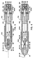
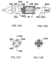
- the nozzle assembly 20 can be threadably connected to the housing 200 or the actuating mechanism 90A such that it can be readily attached and detached, as better shown in Figs. 12 and 13.
- Alternatively, other known structures for mounting or attaching two components can be utilized as well to detachably mate the nozzle assembly 20 to the housing 200.
- the needleless injector 10 can be reused with various nozzle assemblies 20 that may contain different medications to allow for injection of various medications or medications of different doses either together or at different times.
- the nozzle assembly 20 can be prefilled with medication and disposed of after each use.
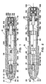
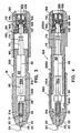
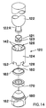
- the nozzle assembly 20, 20A shown in Figs. 1-6 and Fig. 12 includes a cylindrical ampule chamber 26 terminating in a right circular cone 28.
- the nozzle assembly 20B shown in Fig. 11 also includes a cylindrical ampule chamber 26, but terminates in a convex cone 28' where the wall converges with a convex curvature.
- a plunger 30 having a pressure wall contoured to the cone 28, 28' is positioned to slide within the ampule chamber 26.
- the thickness or depth D of the enlarged head is less than the width W provided between an end wall 30e and the tabs to allow free play or gap defined by W - D, a gap of at least about 3.5mm being preferred.
- the enlarged end 58c is dimensioned to freely move relative to the plunger 30C within the gap, but prevented from being disengaged from the plunger during use.
- the tabs 30d engage the shoulder portion 58d of the piston 58, and the entire plunger, including the prongs, is confined within the ampule chamber.
- the prongs are dimensioned to slide inside the ampule chamber the inner wall of the chamber confines the prongs from moving laterally outwardly, thus maintaining the piston engaged to the plunger during use.
Abstract
Description
Claims (11)
- Device (10) for injecting a medical product comprising:a nozzle assembly (20) having a chamber (26) for holding the medical product, an orifice (24) in the nozzle assembly (20) in fluid communication with the chamber (26) for allowing passage of the medical product through the orifice (24), and a pressure wall member disposed and movable within the chamber (26) holding the medical product; andan energy mechanism (40) that includes a piston (58) which is operatively associated with the pressure wall member for moving the pressure wall member at a speed sufficient to eject the medical product from the chamber (26) under a pressure which is sufficient to pierce at least one layer of skin and which is substantially constant during the injection, the energy mechanism (40) comprising a gas spring (50) that has a sealed gas pressure chamber (51) which contains a pressurized gas and receives the piston (58) to compress the gas prior to firing wherein the gas pressure in the chamber (51) remains substantially unchanged so that the medical product can be ejected under the substantially constant pressure.
- Device according to claim 1, wherein the piston (58) slidingly extends through the chamber (51); the device (10) further comprises a trigger mechanism (100) for operatively and selectively engaging and disengaging the piston (58) to selectively retain the gas spring (50) in a locked and compressed condition and for selectively releasing the gas spring (50) in a locked compressed condition and for selectively releasing the gas spring (50) to its relaxed condition, and a gas spring coupling mechanism (70) connected to the proximal end of the piston (58) and which is received by the trigger mechanism (100); and the nozzle assembly (20) and the gas spring (50) are operatively disposed within a housing member (200).
- Device (10) according to claim 2, wherein the distal end of the piston (58) is larger than the proximal end and at least a portion of the proximal end is disposed within the pressure chamber (26) when the pressure chamber (26) is in the relaxed condition, with the pressurized gas within the pressure chamber (26) being further compressed when the distal end is moved into the chamber (26); and wherein the energy mechanism (40) further comprises an actuating member (90) movably connected to the housing member (200), such that the actuating member (90) is movable longitudinally relative to the sealed gas pressure chamber (26) such that the actuating member (90) is capable of moving the distal end of the piston (58) into the pressure chamber (26), as well as moving the gas spring coupling mechanism (70) into the trigger mechanism (100) for holding the gas spring (50) in the compressed condition.
- Device (10) according to claim 3, wherein the nozzle assembly (20) is removably connected to the housing member, wherein the piston (58) is removably and operatively connected to the pressure wall member with the pressure wall member being in the form of a plunger (30), and further comprising a lost motion connection mechanism disposed between the piston (58) and the plunger (30) such that the piston (58) is movable along a predetermined distance (34) before contacting the plunger (30).
- Device (10) according to claim 4, wherein the lost motion connection mechanism comprises a ram (32) which defines a longitudinal slot and which is connected to the piston (58), wherein the plunger (30) further includes a connector shaft (31) operatively and slidingly received within the slot and having a predetermined length to provide a predetermined gap between the plunger (30) and the ram (32), wherein the ram (32) engages the plunger (30) after travelling across the gap.
- Device (10) according to claim 4, wherein the lost motion assembly comprises a resilient quick release connector comprising a plurality of resilient prongs (30a) extending from the plunger (30) toward the piston, wherein the piston (58) has an enlarged head which is slidingly received by the resilient prongs (30a), with each prong (30a) having a radially inwardly extending tab (30d) to limit the longitudinal movement of the enlarged head, such that when the plunger (30) is received inside the ampule chamber (26), the prongs (30a) are prevented from extending in a radially outward direction to retain the enlarged head within the quick release connector; and when the nozzle assembly (20) is removed from the device (10), the prongs (30a) are exposed to user manipulation such that the plunger (30) can be separated from the piston (58).
- Device (10) according to claim 4, wherein the nozzle assembly (20) is prefilled with the medical product and wherein the nozzle assembly (20) or plunger (30) or both are formed of stainless steel, polycarbonate, polypropylene and derivatives thereof or any other suitable plastic, glass or composite that is compatible with the medical product and capable of withstanding pressure and stress subjected thereto.
- Device (10) according to claim 2, wherein the sealed gas spring pressure chamber is defined by a tubular sleeve (52) and a pair of end plugs (54,56) sealingly enclosing the tubular sleeve (52), and wherein the piston (30) is slidingly received between the end plugs (54,56).
- Device (10) according to claim 1 further comprising a coupling device for coupling a medication supply vial to the nozzle assembly (20), the coupling device comprising:a generally hollow main body (124) having proximal and distal ends (126,128);a dividing wall (130) positioned between the proximal and distal ends (126,128), the wall (130) having proximal and distal sides (130A,130B) and a hole (130C) defined by the dividing wall (130);a hollow probe (132) extending axially from the distal side (130B) of the dividing wall (130) toward the distal end of the main body (124) and terminating within the main body (124) such that the probe (132) remains within the main body (124), and the probe (132) is aligned with the hole (130C) to permit fluid communication therebetween;a medication supply vial connector formed on the distal end of the main body (124), such that the supply vial is insertable into the vial connector and removal of the supply vial is thereafter inhibited; anda nozzle connector (150) formed on the proximal end, wherein the connector (150) has a plurality of quick release members (152,152') capable of connecting to a portion of the nozzle assembly (20) and capable of separating from the nozzle assembly (20) when a sufficient separating force is applied thereto, and wherein the probe (132) punctures a seal on the supply vial upon connection of the supply vial to the nozzle assembly (20).
- Device (10) according to claim 9, wherein the coupling device further comprises:a stretchable diaphragm seal member (160) abutting the second side (130B) of the wall (130), the seal member (130B) having an open or zero diameter hole generally in alignment with the dividing wall hole (130);a ring (170) abutting the seal member (160), wherein the ring (170) is provided with a configuration of the nozzle assembly (20) to permit insertion thereof; anda protective cap (180) for protecting and closing the proximal end, wherein the cap (180) has at least one mating member for engaging the quick release member.
- Device (10) according to claim 9, wherein the medication supply vial connector (140) comprises at least one flexible tooth (142) extending toward the wall (130), wherein a free end of the tooth engages a portion of the supply vial (122), and the vial portion has means (121) cooperating with the tooth (142) to prevent removal of the vial (122) therefrom; the quick release members (152,152') extend substantially in an axial direction of the main body and are resilient to enable the quick release members (152,152') to expand radially away from the nozzle and to return substantially to its original position when fully attached thereto; and each of the release members (152,152') has a radially inwardly projecting tab (152A), the tab (152A) cooperating with the nozzle assembly (20) to permit the coupling device (10) to be attached thereto.
Applications Claiming Priority (3)
| Application Number | Priority Date | Filing Date | Title |
|---|---|---|---|
| US08/369,812 US5599302A (en) | 1995-01-09 | 1995-01-09 | Medical injection system and method, gas spring thereof and launching device using gas spring |
| US369812 | 1995-01-09 | ||
| PCT/US1996/000086 WO1996021482A2 (en) | 1995-01-09 | 1996-01-11 | Medical injection system comprising a gas spring |
Publications (2)
| Publication Number | Publication Date |
|---|---|
| EP0802809A2 EP0802809A2 (en) | 1997-10-29 |
| EP0802809B1 true EP0802809B1 (en) | 2003-04-16 |
Family
ID=23457035
Family Applications (1)
| Application Number | Title | Priority Date | Filing Date |
|---|---|---|---|
| EP96902588A Expired - Lifetime EP0802809B1 (en) | 1995-01-09 | 1996-01-11 | Medical injection system comprising a gas spring |
Country Status (8)
| Country | Link |
|---|---|
| US (4) | US5599302A (en) |
| EP (1) | EP0802809B1 (en) |
| JP (1) | JPH10512165A (en) |
| AT (1) | ATE237380T1 (en) |
| AU (1) | AU4693596A (en) |
| DE (1) | DE69627474D1 (en) |
| TW (1) | TW387814B (en) |
| WO (1) | WO1996021482A2 (en) |
Families Citing this family (625)
| Publication number | Priority date | Publication date | Assignee | Title |
|---|---|---|---|---|
| KR100223616B1 (en) * | 1993-07-31 | 1999-10-15 | 웨스톤 테렌스 에드워드 | Needleless injector |
| FR2718357B1 (en) * | 1994-04-06 | 1997-10-03 | Defarges Alain Moreau | Improvements made to a needleless jet injection device. |
| US6474369B2 (en) | 1995-05-26 | 2002-11-05 | Penjet Corporation | Apparatus and method for delivering a lyophilized active with a needle-less injector |
| US5899879A (en) * | 1995-12-19 | 1999-05-04 | Genesis Medical Technologies, Inc. | Spring-actuated needleless injector |
| US5921967A (en) | 1996-02-29 | 1999-07-13 | Medi-Ject Corporation | Plunger for nozzle assembly |
| US5800388A (en) | 1996-02-29 | 1998-09-01 | Medi-Ject Corporation | Plunger/ram assembly adapted for a fluid injector |
| US5769138A (en) * | 1996-04-01 | 1998-06-23 | Medi-Ject Corporation | Nozzle and adapter for loading medicament into an injector |
| US6374255B1 (en) | 1996-05-21 | 2002-04-16 | Immersion Corporation | Haptic authoring |
| US6458574B1 (en) | 1996-09-12 | 2002-10-01 | Transkaryotic Therapies, Inc. | Treatment of a α-galactosidase a deficiency |
| US5875976A (en) * | 1996-12-24 | 1999-03-02 | Medi-Ject Corporation | Locking mechanism for nozzle assembly |
| US6761726B1 (en) * | 1998-05-15 | 2004-07-13 | Pyng Medical Corp. | Method and apparatus for the intraosseous introduction of a device such as an infusion tube |
| US7347840B2 (en) * | 2000-03-02 | 2008-03-25 | Pyng Medical Corp. | Patch for locating a target zone for penetration |
| US5911703A (en) * | 1997-05-22 | 1999-06-15 | Avant Drug Delivery Systems, Inc. | Two-stage fluid medicament jet injector |
| US6030399A (en) * | 1997-06-04 | 2000-02-29 | Spectrx, Inc. | Fluid jet blood sampling device and methods |
| US5947928A (en) * | 1997-06-19 | 1999-09-07 | Mile Creek Capital, Llc | Drug delivery system |
| US6004287A (en) * | 1997-09-23 | 1999-12-21 | Loomis; Dale J | Biolistic apparatus for delivering substances into cells and tissues |
| US6071272A (en) * | 1997-10-28 | 2000-06-06 | Hoffman; Alan S. | Method for treating erectile dysfunctionality |
| US6256011B1 (en) | 1997-12-03 | 2001-07-03 | Immersion Corporation | Multi-function control device with force feedback |
| US6610042B2 (en) | 1997-12-05 | 2003-08-26 | Felton Medical, Inc. | Disposable unit-dose jet-injection syringe for pre-filled and/or transfilled liquid injectable medical drug or vaccine products and method thereof |
| AU767122B2 (en) * | 1998-06-10 | 2003-10-30 | Georgia Tech Research Corporation | Microneedle devices and methods of manufacture and use thereof |
| US6503231B1 (en) * | 1998-06-10 | 2003-01-07 | Georgia Tech Research Corporation | Microneedle device for transport of molecules across tissue |
| JP2002521147A (en) * | 1998-07-27 | 2002-07-16 | メディ−ジェクト コーポレイション | Loading mechanism for use in medical syringe assemblies |
| KR100622160B1 (en) * | 1998-07-27 | 2006-09-07 | 안타레스 팔마, 인코퍼레이티드 | Injection-assisting probe for medical injector assembly |
| US6428528B2 (en) | 1998-08-11 | 2002-08-06 | Antares Pharma, Inc. | Needle assisted jet injector |
| JP2000107289A (en) * | 1998-10-05 | 2000-04-18 | Showa Yakuhin Kako Kk | Cartridge type dental syringe unit |
| US6506177B2 (en) * | 1998-10-14 | 2003-01-14 | Sergio Landau | Needle-less injection system |
| US6406455B1 (en) * | 1998-12-18 | 2002-06-18 | Biovalve Technologies, Inc. | Injection devices |
| DE19859137C1 (en) * | 1998-12-21 | 2000-05-18 | Ferton Holding Sa | High pressure medicinal injection unit includes piston advanced into pressure chamber by series of resilient impacts, forcing fluid out in series of impulses for precise low-volume dosing |
| US6258062B1 (en) * | 1999-02-25 | 2001-07-10 | Joseph M. Thielen | Enclosed container power supply for a needleless injector |
| US7060048B1 (en) * | 1999-04-16 | 2006-06-13 | Powerject Research Limited | Needleless syringe |
| WO2000064514A1 (en) * | 1999-04-22 | 2000-11-02 | Gilbert Garitano | Needleless permanent makeup and tattoo device |
| US7171264B1 (en) * | 1999-05-10 | 2007-01-30 | Genetronics, Inc. | Intradermal delivery of active agents by needle-free injection and electroporation |
| US7192713B1 (en) | 1999-05-18 | 2007-03-20 | President And Fellows Of Harvard College | Stabilized compounds having secondary structure motifs |
| EP1754488A1 (en) | 1999-05-24 | 2007-02-21 | Introgen Therapeutics, Inc. | Methods and compositions for non-viral gene therapy for treatment of hyperproliferative diseases |
| US6611707B1 (en) | 1999-06-04 | 2003-08-26 | Georgia Tech Research Corporation | Microneedle drug delivery device |
| US6743211B1 (en) * | 1999-11-23 | 2004-06-01 | Georgia Tech Research Corporation | Devices and methods for enhanced microneedle penetration of biological barriers |
| US7074210B2 (en) * | 1999-10-11 | 2006-07-11 | Felton International, Inc. | Universal protector cap with auto-disable features for needle-free injectors |
| US6802826B1 (en) | 1999-10-11 | 2004-10-12 | Felton International, Inc. | Universal anti-infectious protector for needleless injectors |
| US6843781B2 (en) * | 1999-10-14 | 2005-01-18 | Becton, Dickinson And Company | Intradermal needle |
| US20020198509A1 (en) * | 1999-10-14 | 2002-12-26 | Mikszta John A. | Intradermal delivery of vaccines and gene therapeutic agents via microcannula |
| US6494865B1 (en) | 1999-10-14 | 2002-12-17 | Becton Dickinson And Company | Intradermal delivery device including a needle assembly |
| US20020193740A1 (en) | 1999-10-14 | 2002-12-19 | Alchas Paul G. | Method of intradermally injecting substances |
| US6382204B1 (en) | 1999-10-14 | 2002-05-07 | Becton Dickinson And Company | Drug delivery system including holder and drug container |
| US6776776B2 (en) * | 1999-10-14 | 2004-08-17 | Becton, Dickinson And Company | Prefillable intradermal delivery device |
| US6569123B2 (en) | 1999-10-14 | 2003-05-27 | Becton, Dickinson And Company | Prefillable intradermal injector |
| US6569143B2 (en) | 1999-10-14 | 2003-05-27 | Becton, Dickinson And Company | Method of intradermally injecting substances |
| WO2001030425A1 (en) | 1999-10-22 | 2001-05-03 | Antares Pharma, Inc. | Medical injector and medicament loading system for use therewith |
| US6673035B1 (en) * | 1999-10-22 | 2004-01-06 | Antares Pharma, Inc. | Medical injector and medicament loading system for use therewith |
| US6391003B1 (en) | 1999-10-25 | 2002-05-21 | Antares Pharma, Inc. | Locking mechanism for a jet injector |
| US7887506B1 (en) | 1999-11-23 | 2011-02-15 | Pulse Needlefree Systems, Inc. | Safety mechanism to prevent accidental patient injection and methods of same |
| US7029457B2 (en) * | 1999-11-23 | 2006-04-18 | Felton International, Inc. | Jet injector with hand piece |
| US6770054B1 (en) | 1999-11-23 | 2004-08-03 | Felton International, Inc. | Injector assembly with driving means and locking means |
| US6693626B1 (en) | 1999-12-07 | 2004-02-17 | Immersion Corporation | Haptic feedback using a keyboard device |
| WO2001051109A1 (en) * | 2000-01-07 | 2001-07-19 | Biovalve Technologies, Inc. | Injection device |
| CA2331030A1 (en) * | 2000-02-16 | 2001-08-16 | Roche Diagnostics Gmbh | Hypodermic needleless injection system |
| US6689092B2 (en) * | 2000-03-03 | 2004-02-10 | Boehringer International Gmbh | Needle-less injector of miniature type |
| WO2001070309A1 (en) * | 2000-03-23 | 2001-09-27 | Antares Pharma, Inc. | Single use disposable jet injector |
| GB0008494D0 (en) | 2000-04-07 | 2000-05-24 | Secr Defence | Microprojectile delivery system |
| US10293056B1 (en) | 2000-05-24 | 2019-05-21 | Board Of Regents, The University Of Texas System | Methods and compositions for non-viral gene therapy for treatment of hyperproliferative diseases |
| US6629958B1 (en) | 2000-06-07 | 2003-10-07 | Ronald P. Spinello | Leak sealing needle |
| US6406456B1 (en) | 2000-06-08 | 2002-06-18 | Avant Drug Delivery Systems, Inc. | Jet injector |
| CA2415186A1 (en) * | 2000-07-10 | 2002-01-17 | Peter M. Wild | Woody plant injection method and apparatus |
| US6695817B1 (en) | 2000-07-11 | 2004-02-24 | Icu Medical, Inc. | Medical valve with positive flow characteristics |
| DE10034270A1 (en) * | 2000-07-14 | 2002-02-14 | Disetronic Licensing Ag | Storage container with a metering device for the metered delivery of an injectable product to an injection device |
| GB0022742D0 (en) | 2000-09-15 | 2000-11-01 | Smithkline Beecham Biolog | Vaccine |
| US6610033B1 (en) * | 2000-10-13 | 2003-08-26 | Incept, Llc | Dual component medicinal polymer delivery system and methods of use |
| US7575924B2 (en) | 2000-11-13 | 2009-08-18 | Research Development Foundation | Methods and compositions relating to improved lentiviral vectors and their applications |
| AU2003222427B8 (en) * | 2000-11-17 | 2010-04-29 | Vascular Biogenics Ltd. | Promoters exhibiting endothelial cell specificity and methods of using same |
| US8071740B2 (en) * | 2000-11-17 | 2011-12-06 | Vascular Biogenics Ltd. | Promoters exhibiting endothelial cell specificity and methods of using same for regulation of angiogenesis |
| KR20030071780A (en) * | 2000-11-30 | 2003-09-06 | 바이오밸브 테크놀로지스, 인코포레이티드 | Injection systems |
| WO2002045737A2 (en) * | 2000-12-07 | 2002-06-13 | Board Of Regents, The University Of Texas System | Methods of treatment involving human mda-7 |
| EP1345646A2 (en) | 2000-12-14 | 2003-09-24 | Georgia Tech Research Corporation | Microneedle devices and production thereof |
| EP2269639B1 (en) | 2001-02-23 | 2018-11-28 | GlaxoSmithKline Biologicals s.a. | Influenza vaccine formulations for intradermal delivery |
| CA2440983A1 (en) | 2001-03-14 | 2002-09-26 | Penjet Corporation | System and method for removing dissolved gas from a solution |
| GB0109297D0 (en) | 2001-04-12 | 2001-05-30 | Glaxosmithkline Biolog Sa | Vaccine |
| US20050192530A1 (en) * | 2001-04-13 | 2005-09-01 | Penjet Corporation | Method and apparatus for needle-less injection with a degassed fluid |
| US6613010B2 (en) | 2001-04-13 | 2003-09-02 | Penjet Corporation | Modular gas-pressured needle-less injector |
| WO2002087663A2 (en) | 2001-04-27 | 2002-11-07 | Penjet Corporation | Method and apparatus for filling or refilling a needle-less injector |
| TWI228420B (en) | 2001-05-30 | 2005-03-01 | Smithkline Beecham Pharma Gmbh | Novel vaccine composition |
| US20100221284A1 (en) | 2001-05-30 | 2010-09-02 | Saech-Sisches Serumwerk Dresden | Novel vaccine composition |
| US6752781B2 (en) * | 2001-06-08 | 2004-06-22 | Sergio Landau | Durable hypodermic jet injector apparatus and method |
| DE10129583A1 (en) * | 2001-06-20 | 2003-01-09 | Disetronic Licensing Ag | Device and method for injection |
| US20060018877A1 (en) * | 2001-06-29 | 2006-01-26 | Mikszta John A | Intradermal delivery of vacccines and therapeutic agents |
| JP4792670B2 (en) * | 2001-07-23 | 2011-10-12 | 株式会社島津製作所 | Needleless syringe |
| CA2456169C (en) * | 2001-08-02 | 2012-05-22 | Didier Trono | Methods and compositions relating to improved lentiviral vector production systems |
| BR0211894A (en) | 2001-08-17 | 2005-06-28 | Antares Pharma Inc | Method of minimizing and reducing mean glucose levels, treating a medical condition caused by high blood glucose levels and reducing hba1c value in an insulin dependent patient |
| GB2391480B (en) * | 2002-08-05 | 2007-02-28 | Caretek Medical Ltd | Drug delivery system |
| US7615234B2 (en) * | 2001-09-11 | 2009-11-10 | Glide Pharmaceutical Technologies Limited | Drug delivery technology |
| GB2404865B (en) * | 2001-09-11 | 2005-09-28 | Caretek Medical Ltd | Novel drug delivery technology |
| WO2003024507A2 (en) * | 2001-09-19 | 2003-03-27 | Biovalve Technologies, Inc. | Microneedles, microneedle arrays, and systems and methods relating to same |
| EP1471953B1 (en) * | 2001-09-21 | 2011-02-16 | Valeritas, Inc. | Gas pressure actuated microneedle arrays, and systems and methods relating to same |
| CA2500452A1 (en) * | 2001-09-28 | 2003-04-03 | Biovalve Technologies, Inc. | Switchable microneedle arrays and systems and methods relating to same |
| EP1469903A2 (en) * | 2001-09-28 | 2004-10-27 | BioValve Technologies, Inc. | Microneedle with membrane |
| KR20040054699A (en) * | 2001-10-02 | 2004-06-25 | 엥스띠뛰 끌레이톤 드 라 러쉐르쉬 | Methods and compositions relating to restricted expression lentiviral vectors and their applications |
| CN100506284C (en) | 2001-10-19 | 2009-07-01 | 脉管生物生长有限公司 | Polynucleotide constructs, pharmaceutical compositions and methods for targeted downregulation of angiogenesis and anticancer therapy |
| US6824526B2 (en) | 2001-10-22 | 2004-11-30 | Penjet Corporation | Engine and diffuser for use with a needle-less injector |
| GB0125506D0 (en) * | 2001-10-24 | 2001-12-12 | Weston Medical Ltd | Needle free injection method and apparatus |
| US6607510B2 (en) * | 2001-11-09 | 2003-08-19 | Bioject Medical Technologies Inc. | Disposable needle-free injection apparatus and method |
| US20030130614A1 (en) * | 2002-01-09 | 2003-07-10 | Johnson Lanny L. | Device for delivering liquid medications or nutrients and gases to local tissue |
| GB2384527B (en) * | 2002-01-23 | 2004-07-14 | Bespak Plc | Dispensing device |
| US6875205B2 (en) | 2002-02-08 | 2005-04-05 | Alaris Medical Systems, Inc. | Vial adapter having a needle-free valve for use with vial closures of different sizes |
| EP1476210B1 (en) | 2002-02-11 | 2008-09-24 | Antares Pharma, Inc. | Intradermal injector |
| JP2005533000A (en) * | 2002-03-05 | 2005-11-04 | ボード オブ リージェンツ, ザ ユニバーシティ オブ テキサス システム | Method for enhancing immunity induction involving MDA-7 |
| US6904823B2 (en) | 2002-04-03 | 2005-06-14 | Immersion Corporation | Haptic shifting devices |
| US7332469B2 (en) | 2002-04-05 | 2008-02-19 | Board Of Regents The University Of Texas System | Intrapleural single-chain urokinase alone or complexed to its soluble receptor protects against pleural adhesions |
| US20040071686A1 (en) | 2002-04-25 | 2004-04-15 | Treco Douglas A. | Treatment of alpha-galactosidase A deficiency |
| US8338168B2 (en) * | 2002-04-26 | 2012-12-25 | Institut National De La Sante Et De La Recherche Medicale (Inserm) | Chimeric glycoproteins and pseudotyped lentiviral vectors |
| US20040025420A1 (en) * | 2002-05-09 | 2004-02-12 | Peter M. Wild | Injection needle for injecting woody plants |
| US6942638B1 (en) * | 2002-05-30 | 2005-09-13 | Kerry Quinn | Needleless injector and ampule system |
| US11298202B2 (en) | 2002-05-31 | 2022-04-12 | Teleflex Life Sciences Limited | Biopsy devices and related methods |
| US10973545B2 (en) | 2002-05-31 | 2021-04-13 | Teleflex Life Sciences Limited | Powered drivers, intraosseous devices and methods to access bone marrow |
| US7811260B2 (en) | 2002-05-31 | 2010-10-12 | Vidacare Corporation | Apparatus and method to inject fluids into bone marrow and other target sites |
| US8690791B2 (en) | 2002-05-31 | 2014-04-08 | Vidacare Corporation | Apparatus and method to access the bone marrow |
| US8142365B2 (en) * | 2002-05-31 | 2012-03-27 | Vidacare Corporation | Apparatus and method for accessing the bone marrow of the sternum |
| US9314228B2 (en) * | 2002-05-31 | 2016-04-19 | Vidacare LLC | Apparatus and method for accessing the bone marrow |
| US8668698B2 (en) | 2002-05-31 | 2014-03-11 | Vidacare Corporation | Assembly for coupling powered driver with intraosseous device |
| CA2485904C (en) | 2002-05-31 | 2013-05-21 | Vidacare Corporation | Apparatus and method to access the bone marrow |
| US9072543B2 (en) | 2002-05-31 | 2015-07-07 | Vidacare LLC | Vascular access kits and methods |
| US8641715B2 (en) | 2002-05-31 | 2014-02-04 | Vidacare Corporation | Manual intraosseous device |
| US11337728B2 (en) | 2002-05-31 | 2022-05-24 | Teleflex Life Sciences Limited | Powered drivers, intraosseous devices and methods to access bone marrow |
| US9545243B2 (en) | 2002-05-31 | 2017-01-17 | Vidacare LLC | Bone marrow aspiration devices and related methods |
| US10973532B2 (en) | 2002-05-31 | 2021-04-13 | Teleflex Life Sciences Limited | Powered drivers, intraosseous devices and methods to access bone marrow |
| US7951089B2 (en) | 2002-05-31 | 2011-05-31 | Vidacare Corporation | Apparatus and methods to harvest bone and bone marrow |
| US20070049945A1 (en) | 2002-05-31 | 2007-03-01 | Miller Larry J | Apparatus and methods to install, support and/or monitor performance of intraosseous devices |
| US8656929B2 (en) | 2002-05-31 | 2014-02-25 | Vidacare Corporation | Medical procedures trays and related methods |
| AU2003247707A1 (en) * | 2002-07-03 | 2004-01-23 | Peter M. Wild | Plant injection method and apparatus |
| KR101170653B1 (en) | 2002-08-12 | 2012-08-03 | 제네렉스, 인코포레이티드 | Methods and compositions concerning poxviruses and cancer |
| AU2003285886A1 (en) | 2002-10-15 | 2004-05-04 | Immersion Corporation | Products and processes for providing force sensations in a user interface |
| WO2004041331A1 (en) * | 2002-11-01 | 2004-05-21 | Antares Pharma, Inc. | Administration of insulin by jet injection |
| DK1563069T3 (en) * | 2002-11-22 | 2012-07-23 | Inst Clayton De La Rech | COMPOSITIONS AND SYSTEMS FOR REGULATION |
| ES2545619T3 (en) | 2003-01-31 | 2015-09-14 | The Mount Sinai School Of Medicine Of New York University | Combination therapy to treat protein deficiency disorders |
| WO2004078124A2 (en) * | 2003-03-03 | 2004-09-16 | Board Of Regents, The University Of Texas System | Methods and compositions involving mda-7 |
| US6802455B1 (en) * | 2003-03-26 | 2004-10-12 | Willie V. Evans | Atomizer |
| FR2853837B1 (en) * | 2003-04-16 | 2006-01-13 | Crossject | DEVICE FOR CONNECTING AN ACTIVE PRINCIPLE RESERVOIR TO AN INJECTION NOZZLE IN A DEVICE FOR INJECTING SAID ACTIVE PRINCIPLE |
| JP4594233B2 (en) * | 2003-05-09 | 2010-12-08 | 竜一 森下 | Needleless syringe containing medicine |
| AU2004272972A1 (en) | 2003-05-22 | 2005-03-24 | Fraunhofer Usa, Inc. | Recombinant carrier molecule for expression, delivery and purification of target polypeptides |
| US9504477B2 (en) | 2003-05-30 | 2016-11-29 | Vidacare LLC | Powered driver |
| US8992322B2 (en) | 2003-06-09 | 2015-03-31 | Immersion Corporation | Interactive gaming systems with haptic feedback |
| HU225252B1 (en) * | 2003-08-21 | 2006-08-28 | S Istvan Lindmayer | Needleless injection apparatus |
| WO2005034949A1 (en) * | 2003-09-09 | 2005-04-21 | University Of Florida | Desferrithiocin derivatives and their use as iron chelators |
| WO2005082396A2 (en) * | 2003-12-01 | 2005-09-09 | Introgen Therapeutics, Inc. | Use of mda-7 to inhibit infection by pathogenic organisms |
| US7815642B2 (en) * | 2004-01-26 | 2010-10-19 | Vidacare Corporation | Impact-driven intraosseous needle |
| ES2607206T3 (en) * | 2004-01-26 | 2017-03-29 | Vidacare LLC | Manual interosseous device |
| EP1722842A1 (en) * | 2004-01-26 | 2006-11-22 | The Medical House Plc | Needle-free injection device |
| US20070281041A1 (en) * | 2004-03-02 | 2007-12-06 | Introgen Therapeutics, Inc. | Compositions and Methods Involving MDA-7 for the Treatment of Cancer |
| DE102004017971A1 (en) * | 2004-04-12 | 2005-10-27 | Leica Microsystems (Schweiz) Ag | Stand, especially for surgical microscopes, with a force storage element |
| DE102004017970A1 (en) * | 2004-04-12 | 2005-10-27 | Leica Microsystems (Schweiz) Ag | Stand, especially for surgical microscopes, with a force storage element |
| DE102005018305A1 (en) * | 2004-05-25 | 2005-12-22 | Tecpharma Licensing Ag | Dosing unit comprises a dose-adjusting unit, which is rotated to adjust the dose, and a graduated scale |
| GB2414406B (en) | 2004-05-28 | 2009-03-18 | Cilag Ag Int | Injection device |
| GB2414403B (en) * | 2004-05-28 | 2009-01-07 | Cilag Ag Int | Injection device |
| GB2414399B (en) * | 2004-05-28 | 2008-12-31 | Cilag Ag Int | Injection device |
| GB2414402B (en) * | 2004-05-28 | 2009-04-22 | Cilag Ag Int | Injection device |
| GB2414400B (en) * | 2004-05-28 | 2009-01-14 | Cilag Ag Int | Injection device |
| US7717874B2 (en) * | 2004-05-28 | 2010-05-18 | Bioject, Inc. | Needle-free injection system |
| GB2414404B (en) | 2004-05-28 | 2009-06-03 | Cilag Ag Int | Injection device |
| GB2414775B (en) * | 2004-05-28 | 2008-05-21 | Cilag Ag Int | Releasable coupling and injection device |
| GB2414409B (en) * | 2004-05-28 | 2009-11-18 | Cilag Ag Int | Injection device |
| GB2414405B (en) * | 2004-05-28 | 2009-01-14 | Cilag Ag Int | Injection device |
| GB2414401B (en) | 2004-05-28 | 2009-06-17 | Cilag Ag Int | Injection device |
| EP1773439A4 (en) * | 2004-07-14 | 2010-01-20 | By Pass Inc | Material delivery system |
| US7615041B2 (en) * | 2004-07-29 | 2009-11-10 | Boston Scientific Scimed, Inc. | Vial adaptor |
| JP4059238B2 (en) * | 2004-09-16 | 2008-03-12 | ソニー株式会社 | Digital signal processing apparatus and digital signal processing method |
| ES2540770T3 (en) | 2004-09-22 | 2015-07-13 | Glaxosmithkline Biologicals Sa | Immunogenic composition for use in staphylococcal vaccination |
| US20060089594A1 (en) * | 2004-10-26 | 2006-04-27 | Sergio Landau | Needle-free injection device |
| US20060089593A1 (en) * | 2004-10-26 | 2006-04-27 | Sergio Landau | Needle-free injection device for individual users |
| US9492400B2 (en) * | 2004-11-04 | 2016-11-15 | Massachusetts Institute Of Technology | Coated controlled release polymer particles as efficient oral delivery vehicles for biopharmaceuticals |
| US20060161115A1 (en) | 2004-11-05 | 2006-07-20 | Fangrow Thomas F | Soft-grip medical connector |
| US8998848B2 (en) | 2004-11-12 | 2015-04-07 | Vidacare LLC | Intraosseous device and methods for accessing bone marrow in the sternum and other target areas |
| JP4960252B2 (en) | 2004-11-22 | 2012-06-27 | インテリジェクト,インコーポレイテッド | Device, system and method for drug delivery |
| EP2532378B1 (en) * | 2004-12-01 | 2016-04-27 | AcuShot, Inc. | Needle-free injector |
| JP5216328B2 (en) | 2005-01-24 | 2013-06-19 | アンタレス ファーマ インコーポレイテッド | Pre-filled needle assist syringe jet injector |
| ES2396745T3 (en) | 2005-02-01 | 2013-02-25 | Intelliject, Inc. | Devices for medication administration |
| GB2422784A (en) * | 2005-02-07 | 2006-08-09 | Caretek Medical Ltd | Disposable assembly comprising a needle or stylet |
| US20070009484A1 (en) * | 2005-02-08 | 2007-01-11 | Board Of Regents, The University Of Texas System | Compositions and methods involving MDA-7 for the treatment of cancer |
| AU2006226543B2 (en) | 2005-03-23 | 2011-10-06 | Glaxosmithkline Biologicals S.A. | Use of an influenza virus an oil-in-water emulsion adjuvant to induce CD4 T-cell and/or improved B-memory cell response |
| ES2614086T3 (en) | 2005-04-04 | 2017-05-29 | University Of Florida Research Foundation, Inc. | Desferritiocin polyether analogs |
| GB2425062B (en) * | 2005-04-06 | 2010-07-21 | Cilag Ag Int | Injection device |
| GB2424837B (en) * | 2005-04-06 | 2010-10-06 | Cilag Ag Int | Injection device |
| GB2424836B (en) * | 2005-04-06 | 2010-09-22 | Cilag Ag Int | Injection device (bayonet cap removal) |
| GB2427826B (en) * | 2005-04-06 | 2010-08-25 | Cilag Ag Int | Injection device comprising a locking mechanism associated with integrally formed biasing means |
| GB2424838B (en) * | 2005-04-06 | 2011-02-23 | Cilag Ag Int | Injection device (adaptable drive) |
| GB2424835B (en) * | 2005-04-06 | 2010-06-09 | Cilag Ag Int | Injection device (modified trigger) |
| US7699802B2 (en) * | 2005-05-03 | 2010-04-20 | Pharmajet, Inc. | Needle-less injector |
| US20070027428A1 (en) * | 2005-05-03 | 2007-02-01 | Pharmajet, Inc. | Vial system and method for needle-less injector |
| US7618393B2 (en) | 2005-05-03 | 2009-11-17 | Pharmajet, Inc. | Needle-less injector and method of fluid delivery |
| EP2932982B1 (en) | 2005-05-17 | 2018-10-03 | Amicus Therapeutics, Inc. | A method for the treatment of pompe disease using 1-deoxynojirimycin and derivatives |
| US20100119525A1 (en) * | 2005-08-01 | 2010-05-13 | Mount Sinai Schoool Of Medicine Of New York University | Method for extending longevity using npc1l1 antagonists |
| EP1919504B1 (en) | 2005-08-03 | 2013-10-16 | iBio, Inc. | Antibody to bacillus anthracis protective antigen |
| US20070055199A1 (en) * | 2005-08-10 | 2007-03-08 | Gilbert Scott J | Drug delivery device for buccal and aural applications and other areas of the body difficult to access |
| DE602005018480D1 (en) | 2005-08-30 | 2010-02-04 | Cilag Gmbh Int | Needle device for a prefilled syringe |
| CA2621982C (en) | 2005-09-07 | 2017-11-28 | Jennerex Biotherapeutics Ulc | Systemic treatment of metastatic and/or systemically-disseminated cancers using gm-csf-expressing poxviruses |
| US8980246B2 (en) | 2005-09-07 | 2015-03-17 | Sillajen Biotherapeutics, Inc. | Oncolytic vaccinia virus cancer therapy |
| US20110098656A1 (en) * | 2005-09-27 | 2011-04-28 | Burnell Rosie L | Auto-injection device with needle protecting cap having outer and inner sleeves |
| US8672879B2 (en) * | 2005-10-13 | 2014-03-18 | Argos Therapeutics, Inc. | Devices, systems and related methods suitable for delivery of a liquid medicament stored at cryogenic temperatures |
| TWI457133B (en) * | 2005-12-13 | 2014-10-21 | Glaxosmithkline Biolog Sa | Novel composition |
| WO2007070682A2 (en) * | 2005-12-15 | 2007-06-21 | Massachusetts Institute Of Technology | System for screening particles |
| WO2007075677A2 (en) * | 2005-12-20 | 2007-07-05 | Antares Pharma, Inc. | Needle-free injection device |
| DE102005062220B3 (en) * | 2005-12-20 | 2007-02-15 | Primojex Gmbh | System for needle-free or needle injection of fluid, e.g. medicament, comprises injection device connectable to needle attachment separable into cannula and adapter parts, allowing changing of needles |
| GB0607088D0 (en) | 2006-04-07 | 2006-05-17 | Glaxosmithkline Biolog Sa | Vaccine |
| CN101378778B (en) | 2005-12-22 | 2013-02-06 | 葛兰素史密丝克莱恩生物有限公司 | Vaccine comprising streptococcus pneumoniae capsular polyaccharide conjugates |
| US20080161755A1 (en) * | 2006-01-27 | 2008-07-03 | Bioject Inc. | Needle-free injection device and priming system |
| WO2007092944A2 (en) * | 2006-02-08 | 2007-08-16 | Introgen Therapeutics, Inc. | Compositions and methods involving gene therapy and proteasome modulation |
| CA2642056A1 (en) * | 2006-02-13 | 2007-08-23 | Fraunhofer Usa, Inc. | Hpv antigens, vaccine compositions, and related methods |
| WO2008048344A2 (en) * | 2006-02-13 | 2008-04-24 | Fraunhofer Usa, Inc. | Bacillus anthracis antigens, vaccine compositions, and related methods |
| EP1984405A4 (en) * | 2006-02-13 | 2010-06-30 | Fraunhofer Usa Inc | Influenza antigens, vaccine compositions, and related methods |
| WO2007106415A2 (en) * | 2006-03-10 | 2007-09-20 | Massachusetts Institute Of Technology | Triggered self-assembly conjugates and nanosystems |
| WO2007111806A2 (en) | 2006-03-23 | 2007-10-04 | Massachusetts Eye And Ear Infirmary | Cyclopentane heptanoic acid compounds for reducing body fat |
| EA015833B1 (en) | 2006-03-30 | 2011-12-30 | Глаксосмитклайн Байолоджикалс С.А. | Immunogenic composition |
| CA2648099C (en) * | 2006-03-31 | 2012-05-29 | The Brigham And Women's Hospital, Inc | System for targeted delivery of therapeutic agents |
| WO2007120638A2 (en) * | 2006-04-12 | 2007-10-25 | President And Fellows Of Harvard College | Methods and compositions for modulating glycosylation |
| WO2007131025A1 (en) | 2006-05-03 | 2007-11-15 | Antares Pharma, Inc. | Injector with adjustable dosing |
| US8251947B2 (en) | 2006-05-03 | 2012-08-28 | Antares Pharma, Inc. | Two-stage reconstituting injector |
| WO2007133807A2 (en) | 2006-05-15 | 2007-11-22 | Massachusetts Institute Of Technology | Polymers for functional particles |
| US20110052697A1 (en) * | 2006-05-17 | 2011-03-03 | Gwangju Institute Of Science & Technology | Aptamer-Directed Drug Delivery |
| GB2438591B (en) * | 2006-06-01 | 2011-07-13 | Cilag Gmbh Int | Injection device |
| GB2438590B (en) | 2006-06-01 | 2011-02-09 | Cilag Gmbh Int | Injection device |
| GB2438593B (en) | 2006-06-01 | 2011-03-30 | Cilag Gmbh Int | Injection device (cap removal feature) |
| EP2492684B1 (en) | 2006-06-02 | 2016-12-28 | President and Fellows of Harvard College | Protein surface remodeling |
| ES2785210T3 (en) * | 2006-06-07 | 2020-10-06 | Acushot Inc | Loading mechanism for a needleless injector |
| WO2007150030A2 (en) | 2006-06-23 | 2007-12-27 | Massachusetts Institute Of Technology | Microfluidic synthesis of organic nanoparticles |
| WO2008001377A2 (en) * | 2006-06-28 | 2008-01-03 | Perf-Action Technologies Ltd. | Needleless injections for administering compositions to the skin |
| DK2043682T3 (en) | 2006-07-17 | 2014-06-02 | Glaxosmithkline Biolog Sa | INFLUENZA VACCINE |
| US9115358B2 (en) * | 2006-08-11 | 2015-08-25 | President And Fellows Of Harvard College | Moenomycin biosynthesis-related compositions and methods of use thereof |
| US20100061990A1 (en) * | 2006-08-14 | 2010-03-11 | Massachusetts Institute Of Technology | Hemagglutinin Polypeptides, and Reagents and Methods Relating Thereto |
| US20090269342A1 (en) * | 2006-08-14 | 2009-10-29 | Massachusetts Institute Of Technology | Hemagglutinin Polypeptides, and Reagents and Methods Relating Thereto |
| ES2805203T3 (en) | 2006-09-12 | 2021-02-11 | Teleflex Medical Devices S A R L | Bone marrow aspiration and biopsy apparatus |
| ES2609923T3 (en) * | 2006-09-12 | 2017-04-25 | Vidacare LLC | Bone marrow biopsy and aspiration device |
| US8944069B2 (en) | 2006-09-12 | 2015-02-03 | Vidacare Corporation | Assemblies for coupling intraosseous (IO) devices to powered drivers |
| KR20150044979A (en) | 2006-09-13 | 2015-04-27 | 임머숀 코퍼레이션 | Systems and methods for casino gaming haptics |
| US8481023B2 (en) | 2006-09-15 | 2013-07-09 | Ottawa Hospital Research Institute | Oncolytic rhabdovirus |
| US7547293B2 (en) * | 2006-10-06 | 2009-06-16 | Bioject, Inc. | Triggering mechanism for needle-free injector |
| JO3598B1 (en) | 2006-10-10 | 2020-07-05 | Infinity Discovery Inc | Boronic acids and esters as inhibitors of fatty acid amide hydrolase |
| BRPI0717219B8 (en) | 2006-10-12 | 2021-05-25 | Glaxosmithkline Biologicals Sa | immunogenic composition, and, use of an immunogenic composition |
| SI2086582T1 (en) | 2006-10-12 | 2013-02-28 | Glaxosmithkline Biologicals S.A. | Vaccine comprising an oil in water emulsion adjuvant |
| US7780201B2 (en) * | 2006-10-13 | 2010-08-24 | Medela Holding Ag | Tube connector with three part construction and latching component |
| BRPI0717401A2 (en) | 2006-10-25 | 2013-11-12 | Icu Medical Inc | CONNECTOR FOR MEDICAL USE |
| US8974410B2 (en) | 2006-10-30 | 2015-03-10 | Vidacare LLC | Apparatus and methods to communicate fluids and/or support intraosseous devices |
| WO2008147456A2 (en) * | 2006-11-20 | 2008-12-04 | Massachusetts Institute Of Technology | Drug delivery systems using fc fragments |
| BRPI0719756A2 (en) | 2006-12-01 | 2014-01-21 | Anterios Inc | Amphiphilic Nanoparticles |
| US20080213377A1 (en) * | 2006-12-08 | 2008-09-04 | Bhatia Sangeeta N | Delivery of Nanoparticles and/or Agents to Cells |
| US20080140001A1 (en) * | 2006-12-12 | 2008-06-12 | By-Pass Inc. | Fluid Delivery Apparatus And Methods |
| DK2474525T3 (en) | 2006-12-26 | 2020-07-13 | Lantheus Medical Imaging Inc | Ligands for imaging cardiac innervation |
| ES2558928T3 (en) | 2007-01-31 | 2016-02-09 | Dana-Farber Cancer Institute, Inc. | Stabilized p53 peptides and uses thereof |
| WO2008098165A2 (en) * | 2007-02-09 | 2008-08-14 | Massachusetts Institute Of Technology | Oscillating cell culture bioreactor |
| US8118814B2 (en) * | 2007-02-14 | 2012-02-21 | Depuy Mitek Inc. | Implement for orientating a tool, particularly useful in surgical tools for harvesting and implanting bone plugs to repair damaged bone tissue |
| DE102007008597A1 (en) | 2007-02-19 | 2008-08-21 | Primojex Gmbh | Fluid injecting system for use through or into epidermis or corium of human skin, has mounting device protecting ampoule body of syringe, and injection device axially adjusting ampoule piston corresponding to given pressure profile |
| WO2008103997A2 (en) * | 2007-02-23 | 2008-08-28 | Bioject Inc. | Needle-free injection devices and drug delivery systems therefor |
| JP5439193B2 (en) | 2007-03-15 | 2014-03-12 | ユニバーシティー オブ フロリダ リサーチ ファンデーション, インク. | Desferrithiocin polyether analogue |
| KR20080084528A (en) | 2007-03-15 | 2008-09-19 | 제네렉스 바이오테라퓨틱스 인크. | Oncolytic vaccinia virus cancer therapy |
| US7960139B2 (en) | 2007-03-23 | 2011-06-14 | Academia Sinica | Alkynyl sugar analogs for the labeling and visualization of glycoconjugates in cells |
| KR101623985B1 (en) | 2007-03-28 | 2016-05-25 | 프레지던트 앤드 펠로우즈 오브 하바드 칼리지 | Stitched polypeptides |
| WO2008124632A1 (en) | 2007-04-04 | 2008-10-16 | Massachusetts Institute Of Technology | Amphiphilic compound assisted nanoparticles for targeted delivery |
| WO2008124634A1 (en) | 2007-04-04 | 2008-10-16 | Massachusetts Institute Of Technology | Polymer-encapsulated reverse micelles |
| WO2008124463A2 (en) | 2007-04-04 | 2008-10-16 | Vidacare Corporation | Powered drivers, intraosseous devices and methods to access bone marrow |
| US8778348B2 (en) * | 2007-04-28 | 2014-07-15 | Ibio Inc. | Trypanosoma antigens, vaccine compositions, and related methods |
| WO2008152639A2 (en) * | 2007-06-12 | 2008-12-18 | Bypass, Inc. | Pressure pulse actuating device for delivery systems |
| JP2010529166A (en) * | 2007-06-14 | 2010-08-26 | クルセル スウィツァーランド アーゲー | Intradermal influenza vaccine |
| US8524444B2 (en) | 2007-06-15 | 2013-09-03 | President And Fellows Of Harvard College | Methods and compositions for detections and modulating O-glycosylation |
| JP2010531330A (en) | 2007-06-26 | 2010-09-24 | グラクソスミスクライン バイオロジカルズ ソシエテ アノニム | Vaccine containing Streptococcus pneumoniae capsular polysaccharide conjugate |
| EP2178558B1 (en) | 2007-07-11 | 2014-04-30 | iBio, Inc. | Yersinia pestis antigens, vaccine compositions, and related methods |
| US20110059130A1 (en) * | 2007-08-20 | 2011-03-10 | Fraunhofer Usa, Inc. | Prophylactic and therapeutic influenza vaccines, antigens, compositions and methods |
| EP2188004A4 (en) | 2007-08-21 | 2015-06-17 | Yukon Medical Llc | Vial access and injection system |
| EP2205074A4 (en) * | 2007-10-04 | 2013-07-31 | Harvard College | Moenomycin analogs, methods of synthesis, and uses thereof |
| WO2009047247A1 (en) * | 2007-10-10 | 2009-04-16 | Shl Group Ab | Medical delivery device |
| EP3424525A1 (en) | 2007-10-12 | 2019-01-09 | Massachusetts Institute Of Technology | Vaccine nanotechnology |
| WO2009086250A1 (en) * | 2007-12-21 | 2009-07-09 | Aesthetic Sciences Corporation | Self-contained pressurized injection device |
| CN101951927A (en) * | 2008-01-03 | 2011-01-19 | 麻省理工学院 | Decoy influenza therapies |
| US8193182B2 (en) | 2008-01-04 | 2012-06-05 | Intellikine, Inc. | Substituted isoquinolin-1(2H)-ones, and methods of use thereof |
| DE102008008023A1 (en) | 2008-02-04 | 2009-08-13 | Primojex Gmbh | System for injecting a fluid through or into the human skin |
| US9486292B2 (en) | 2008-02-14 | 2016-11-08 | Immersion Corporation | Systems and methods for real-time winding analysis for knot detection |
| EP2262554A1 (en) * | 2008-03-07 | 2010-12-22 | Pharmajet, Inc. | Intradermal injector and uses thereof |
| EP2268342B1 (en) | 2008-03-10 | 2015-09-16 | Antares Pharma, Inc. | Injector safety device |
| US9117870B2 (en) * | 2008-03-27 | 2015-08-25 | Lam Research Corporation | High throughput cleaner chamber |
| US8936571B2 (en) * | 2008-03-31 | 2015-01-20 | Laura Devega | Illuminated syringe |
| WO2009146088A1 (en) * | 2008-04-01 | 2009-12-03 | Yukon Medical, Llc | Dual container fluid transfer device |
| TW201000107A (en) * | 2008-04-09 | 2010-01-01 | Infinity Pharmaceuticals Inc | Inhibitors of fatty acid amide hydrolase |
| MX2010011412A (en) | 2008-04-16 | 2010-11-12 | Glaxosmithkline Biolog Sa | Vaccine. |
| JP2011523353A (en) * | 2008-04-28 | 2011-08-11 | プレジデント アンド フェロウズ オブ ハーバード カレッジ | Overcharged protein for cell penetration |
| US8177749B2 (en) | 2008-05-20 | 2012-05-15 | Avant Medical Corp. | Cassette for a hidden injection needle |
| MX2010012691A (en) | 2008-05-20 | 2011-03-30 | Avant Medical Corp Star | Autoinjector system. |
| US8052645B2 (en) | 2008-07-23 | 2011-11-08 | Avant Medical Corp. | System and method for an injection using a syringe needle |
| GB2461086B (en) * | 2008-06-19 | 2012-12-05 | Cilag Gmbh Int | Injection device |
| GB2461084B (en) * | 2008-06-19 | 2012-09-26 | Cilag Gmbh Int | Fluid transfer assembly |
| GB2461089B (en) * | 2008-06-19 | 2012-09-19 | Cilag Gmbh Int | Injection device |
| GB2461085B (en) * | 2008-06-19 | 2012-08-29 | Cilag Gmbh Int | Injection device |
| GB2461088B (en) * | 2008-06-19 | 2012-09-26 | Cilag Gmbh Int | Injection device |
| GB2461087B (en) * | 2008-06-19 | 2012-09-26 | Cilag Gmbh Int | Injection device |
| US20110212157A1 (en) | 2008-06-26 | 2011-09-01 | Anterios, Inc. | Dermal delivery |
| US8680020B2 (en) | 2008-07-15 | 2014-03-25 | Academia Sinica | Glycan arrays on PTFE-like aluminum coated glass slides and related methods |
| CA2734991A1 (en) * | 2008-07-23 | 2010-01-28 | Massachusetts Institute Of Technology | Activation of histone deacetylase 1 (hdac1) protects against dna damage and increases neuronal survival |
| EP2356139A4 (en) | 2008-07-23 | 2013-01-09 | Harvard College | Ligation of stapled polypeptides |
| US20100021472A1 (en) * | 2008-07-25 | 2010-01-28 | Geetha Srikrishna | Methods for diagnosing and treating cancer |
| ES2738539T3 (en) | 2008-08-05 | 2020-01-23 | Antares Pharma Inc | Multi dose injector |
| US8734803B2 (en) | 2008-09-28 | 2014-05-27 | Ibio Inc. | Humanized neuraminidase antibody and methods of use thereof |
| US8591905B2 (en) * | 2008-10-12 | 2013-11-26 | The Brigham And Women's Hospital, Inc. | Nicotine immunonanotherapeutics |
| US8277812B2 (en) | 2008-10-12 | 2012-10-02 | Massachusetts Institute Of Technology | Immunonanotherapeutics that provide IgG humoral response without T-cell antigen |
| US8343498B2 (en) * | 2008-10-12 | 2013-01-01 | Massachusetts Institute Of Technology | Adjuvant incorporation in immunonanotherapeutics |
| US8343497B2 (en) | 2008-10-12 | 2013-01-01 | The Brigham And Women's Hospital, Inc. | Targeting of antigen presenting cells with immunonanotherapeutics |
| CA2743904A1 (en) | 2008-11-17 | 2010-05-20 | The Regents Of The University Of Michigan | Cancer vaccine compositions and methods of using the same |
| WO2010077806A1 (en) | 2008-12-15 | 2010-07-08 | Greenlight Biosciences, Inc. | Methods for control of flux in metabolic pathways |
| CN105132387A (en) * | 2008-12-22 | 2015-12-09 | 绿光生物科学公司 | Compositions and methods for the production of a compound |
| WO2010108116A1 (en) | 2009-03-20 | 2010-09-23 | Antares Pharma, Inc. | Hazardous agent injection system |
| US8454579B2 (en) | 2009-03-25 | 2013-06-04 | Icu Medical, Inc. | Medical connector with automatic valves and volume regulator |
| US20100252373A1 (en) * | 2009-04-02 | 2010-10-07 | Innovative Office Products, Inc. | Friction device for a spring cylinder |
| WO2010118159A1 (en) | 2009-04-07 | 2010-10-14 | Infinity Pharmaceuticals, Inc. | Inhibitors of fatty acid amide hydrolase |
| WO2010118155A1 (en) | 2009-04-07 | 2010-10-14 | Infinity Pharmaceuticals, Inc. | Inhibitors of fatty acid amide hydrolase |
| CA2758271C (en) | 2009-04-09 | 2018-06-05 | Robert Boyd | Methods for preventing and/or treating lysosomal storage disorders |
| JP5685579B2 (en) | 2009-04-14 | 2015-03-18 | ユーコン・メディカル,リミテッド・ライアビリティ・カンパニー | Fluid transfer device |
| WO2010129023A2 (en) | 2009-04-28 | 2010-11-11 | President And Fellows Of Harvard College | Supercharged proteins for cell penetration |
| US8765735B2 (en) * | 2009-05-18 | 2014-07-01 | Infinity Pharmaceuticals, Inc. | Isoxazolines as inhibitors of fatty acid amide hydrolase |
| US9149465B2 (en) * | 2009-05-18 | 2015-10-06 | Infinity Pharmaceuticals, Inc. | Isoxazolines as inhibitors of fatty acid amide hydrolase |
| US8927551B2 (en) * | 2009-05-18 | 2015-01-06 | Infinity Pharmaceuticals, Inc. | Isoxazolines as inhibitors of fatty acid amide hydrolase |
| US9104791B2 (en) | 2009-05-28 | 2015-08-11 | Immersion Corporation | Systems and methods for editing a model of a physical system for a simulation |
| JP2012528858A (en) | 2009-06-01 | 2012-11-15 | プレジデント アンド フェロウズ オブ ハーバード カレッジ | O-GlcNAc transferase inhibitor and use thereof |
| US9163330B2 (en) | 2009-07-13 | 2015-10-20 | President And Fellows Of Harvard College | Bifunctional stapled polypeptides and uses thereof |
| GB0913681D0 (en) | 2009-08-05 | 2009-09-16 | Glaxosmithkline Biolog Sa | Immunogenic composition |
| KR101838472B1 (en) | 2009-09-14 | 2018-03-15 | 신라젠(주) | Oncolytic vaccinia virus combination cancer therapy |
| CA2774973A1 (en) | 2009-09-22 | 2011-03-31 | Aileron Therapeutics, Inc. | Peptidomimetic macrocycles |
| WO2011041391A1 (en) | 2009-09-29 | 2011-04-07 | Fraunhofer Usa, Inc. | Influenza hemagglutinin antibodies, compositions, and related methods |
| US8604057B2 (en) | 2009-10-19 | 2013-12-10 | Amicus Therapeutics, Inc. | Compositions for preventing and/or treating lysosomal storage disorders |
| EP2490532B1 (en) | 2009-10-19 | 2016-11-23 | Amicus Therapeutics, Inc. | Novel compositions for preventing and/or treating degenerative disorders of the central nervous system |
| US10087236B2 (en) | 2009-12-02 | 2018-10-02 | Academia Sinica | Methods for modifying human antibodies by glycan engineering |
| US11377485B2 (en) | 2009-12-02 | 2022-07-05 | Academia Sinica | Methods for modifying human antibodies by glycan engineering |
| MX365946B (en) | 2009-12-10 | 2019-06-19 | Turnstone Lp | Oncolytic rhabdovirus. |
| CA2784807C (en) | 2009-12-29 | 2021-12-14 | Dana-Farber Cancer Institute, Inc. | Type ii raf kinase inhibitors |
| AU2011210840B2 (en) | 2010-01-27 | 2014-12-11 | Massachusetts Institute Of Technology | Engineered polypeptide agents for targeted broad spectrum influenza neutralization |
| RU2015143910A (en) * | 2010-02-03 | 2018-12-28 | Инфинити Фармасьютикалз, Инк. | FATTY ACID AMID HYDROLASE INHIBITORS |
| WO2011112635A1 (en) | 2010-03-08 | 2011-09-15 | Sloan-Kettering Institute For Cancer Research | Cdc7 kinase inhibitors and uses thereof |
| GB201003922D0 (en) | 2010-03-09 | 2010-04-21 | Glaxosmithkline Biolog Sa | Conjugation process |
| GB201003920D0 (en) | 2010-03-09 | 2010-04-21 | Glaxosmithkline Biolog Sa | Method of treatment |
| US9102697B2 (en) | 2010-03-22 | 2015-08-11 | President And Fellows Of Harvard College | Trioxacarcins and uses thereof |
| USD644731S1 (en) | 2010-03-23 | 2011-09-06 | Icu Medical, Inc. | Medical connector |
| WO2011130332A1 (en) | 2010-04-12 | 2011-10-20 | Academia Sinica | Glycan arrays for high throughput screening of viruses |
| WO2011140296A1 (en) | 2010-05-05 | 2011-11-10 | Infinity Pharmaceuticals | Triazoles as inhibitors of fatty acid synthase |
| EP2566853B1 (en) | 2010-05-05 | 2017-01-25 | Infinity Pharmaceuticals, Inc. | Tetrazolones as inhibitors of fatty acid synthase |
| EP2566953B1 (en) | 2010-05-07 | 2019-01-02 | Greenlight Biosciences, Inc. | Methods for control of flux in metabolic pathways through enzyme relocation |
| BR122020018186B1 (en) | 2010-05-11 | 2021-07-27 | Lantheus Medical Imaging, Inc | USE OF IMAGING AGENTS TO PREPARE A COMPOSITION FOR DETECTION OF THE NOREPINEPHRIN CONVEYOR (NET) AND METHOD FOR THE DETECTION OF NET |
| US8758306B2 (en) | 2010-05-17 | 2014-06-24 | Icu Medical, Inc. | Medical connectors and methods of use |
| USD655017S1 (en) | 2010-06-17 | 2012-02-28 | Yukon Medical, Llc | Shroud |
| ES2664872T3 (en) | 2010-06-18 | 2018-04-23 | Taiho Pharmaceutical Co., Ltd | PRPK-TPRKB modulators and their uses |
| CA2807552A1 (en) | 2010-08-06 | 2012-02-09 | Moderna Therapeutics, Inc. | Engineered nucleic acids and methods of use thereof |
| DK2603600T3 (en) | 2010-08-13 | 2019-03-04 | Aileron Therapeutics Inc | PEPTIDOMIMETIC MACROCYCLES |
| EP2611922A1 (en) | 2010-08-31 | 2013-07-10 | Greenlight Biosciences, Inc. | Methods for control of flux in metabolic pathways through protease manipulation |
| US8802110B2 (en) | 2010-09-21 | 2014-08-12 | Massachusetts Institute Of Technology | Influenza treatment and/or characterization, human-adapted HA polypeptides; vaccines |
| WO2012040459A2 (en) | 2010-09-22 | 2012-03-29 | President And Fellows Of Harvard College | Beta-catenin targeting peptides and uses thereof |
| EP4108671A1 (en) | 2010-10-01 | 2022-12-28 | ModernaTX, Inc. | Modified nucleosides, nucleotides, and nucleic acids, and uses thereof |
| BR112013007946B1 (en) | 2010-10-04 | 2022-07-12 | Massachusetts Institute Of Technology | PHARMACEUTICAL AND IMMUNOGENIC COMPOSITIONS COMPRISING HEMAGGLUTININ POLYPEPTIDES |
| WO2012064973A2 (en) | 2010-11-10 | 2012-05-18 | Infinity Pharmaceuticals, Inc. | Heterocyclic compounds and uses thereof |
| RU2603426C2 (en) * | 2010-11-19 | 2016-11-27 | Байер Консьюмер Кеэр Аг | Applicator device of handle-pressing type and method for its use |
| KR101224581B1 (en) | 2010-12-10 | 2013-01-21 | 주식회사 모리스 | Cap with Automatic Sealing Structure in Tube Container |
| GB201021716D0 (en) * | 2010-12-22 | 2011-02-02 | Owen Mumford Ltd | Autoinjectors |
| JP6121910B2 (en) | 2011-01-04 | 2017-04-26 | シラジェン バイオセラピューティクス インコーポレイテッド | Generation of antibodies against tumor antigens and tumor-specific complement-dependent cytotoxicity by administration of oncolytic vaccinia virus |
| CN103370092B (en) * | 2011-01-10 | 2016-09-28 | 周吉尼克斯股份有限公司 | Needleless injector |
| UA115767C2 (en) | 2011-01-10 | 2017-12-26 | Інфініті Фармасьютікалз, Інк. | Processes for preparing isoquinolinones and solid forms of isoquinolinones |
| US9089579B2 (en) | 2011-01-19 | 2015-07-28 | Topokine Therapeutics, Inc. | Methods and compositions for treating metabolic syndrome |
| KR20140005998A (en) | 2011-01-24 | 2014-01-15 | 안테리오스, 인코퍼레이티드 | Nanoparticle compositions, formulations thereof, and uses therefor |
| DK2667854T3 (en) | 2011-01-24 | 2019-04-23 | Anterios Inc | NANO PARTICLE FORMATIONS |
| WO2012103037A1 (en) | 2011-01-24 | 2012-08-02 | Anterios, Inc. | Oil compositions |
| US8703818B2 (en) | 2011-03-03 | 2014-04-22 | Tersus Pharmaceuticals, LLC | Compositions and methods comprising C16:1n7-palmitoleate |
| GB201103836D0 (en) | 2011-03-07 | 2011-04-20 | Glaxosmithkline Biolog Sa | Conjugation process |
| US9193767B2 (en) | 2011-03-30 | 2015-11-24 | Brown University | Enopeptins, uses thereof, and methods of synthesis thereto |
| AU2012236099A1 (en) | 2011-03-31 | 2013-10-03 | Moderna Therapeutics, Inc. | Delivery and formulation of engineered nucleic acids |
| JP6026501B2 (en) * | 2011-04-04 | 2016-11-16 | イデー インターナショナル アールアンドディー インコーポレイテッドIdee International R&D Inc. | Needleless syringe wand assembly |
| KR20140025475A (en) * | 2011-04-19 | 2014-03-04 | 인비지덤, 엘엘씨 | Method of producing substances with supersaturated gas??transdermal delivery device thereof??and uses thereof |
| US10092706B2 (en) | 2011-04-20 | 2018-10-09 | Amgen Inc. | Autoinjector apparatus |
| CN103533953A (en) | 2011-05-17 | 2014-01-22 | 葛兰素史密丝克莱恩生物有限公司 | Vaccine against streptococcus pneumoniae |
| US9364532B2 (en) | 2011-06-08 | 2016-06-14 | Children's Hospital Of Eastern Ontario Research Institute Inc. | Compositions and methods for glioblastoma treatment |
| WO2012177997A1 (en) | 2011-06-22 | 2012-12-27 | The General Hospital Corporation | Treatment of proteinopathies |
| US9220660B2 (en) | 2011-07-15 | 2015-12-29 | Antares Pharma, Inc. | Liquid-transfer adapter beveled spike |
| US8496619B2 (en) | 2011-07-15 | 2013-07-30 | Antares Pharma, Inc. | Injection device with cammed ram assembly |
| AU2012284091B2 (en) | 2011-07-19 | 2015-11-12 | Infinity Pharmaceuticals Inc. | Heterocyclic compounds and uses thereof |
| US8969363B2 (en) | 2011-07-19 | 2015-03-03 | Infinity Pharmaceuticals, Inc. | Heterocyclic compounds and uses thereof |
| PT2734510T (en) | 2011-07-22 | 2019-02-13 | Massachusetts Inst Technology | Activators of class i histone deacetlyases (hdacs) and uses thereof |
| US9408972B2 (en) | 2011-08-02 | 2016-08-09 | Pharmajet, Inc. | Needle-free injection device |
| WO2013032591A1 (en) | 2011-08-29 | 2013-03-07 | Infinity Pharmaceuticals Inc. | Heterocyclic compounds and uses thereof |
| USD681230S1 (en) | 2011-09-08 | 2013-04-30 | Yukon Medical, Llc | Shroud |
| CN104159890B (en) | 2011-09-09 | 2018-04-10 | 蓝瑟斯医学影像公司 | Composition, method and system for synthesizing and using developer |
| CA2846893A1 (en) | 2011-09-09 | 2013-03-14 | Greenlight Biosciences, Inc. | Cell-free preparation of carbapenems |
| EP2755693A4 (en) | 2011-09-12 | 2015-05-20 | Moderna Therapeutics Inc | Engineered nucleic acids and methods of use thereof |
| US9630979B2 (en) | 2011-09-29 | 2017-04-25 | Infinity Pharmaceuticals, Inc. | Inhibitors of monoacylglycerol lipase and methods of their use |
| CN103974724B (en) | 2011-10-03 | 2019-08-30 | 现代泰克斯公司 | Nucleosides, nucleotide and nucleic acid of modification and application thereof |
| US20130096170A1 (en) | 2011-10-14 | 2013-04-18 | Hospira, Inc. | Methods of treating pediatric patients using dexmedetomidine |
| US9096684B2 (en) | 2011-10-18 | 2015-08-04 | Aileron Therapeutics, Inc. | Peptidomimetic macrocycles |
| JP6106685B2 (en) | 2011-11-17 | 2017-04-05 | ダナ−ファーバー キャンサー インスティテュート, インコーポレイテッド | Inhibitors of C-JUN-N-terminal kinase (JNK) |
| GB201119999D0 (en) | 2011-11-20 | 2012-01-04 | Glaxosmithkline Biolog Sa | Vaccine |
| GB201120000D0 (en) | 2011-11-20 | 2012-01-04 | Glaxosmithkline Biolog Sa | Vaccine |
| RU2627632C2 (en) | 2011-12-13 | 2017-08-09 | Фармаджет Инк. | Needle-free intradermal injection device |
| WO2013090750A1 (en) | 2011-12-16 | 2013-06-20 | University Of Florida Research Foundation, Inc. | Uses of 4'-desferrithiocin analogs |
| CA2859387A1 (en) | 2011-12-16 | 2013-06-20 | Moderna Therapeutics, Inc. | Modified nucleoside, nucleotide, and nucleic acid compositions |
| US8426471B1 (en) | 2011-12-19 | 2013-04-23 | Topokine Therapeutics, Inc. | Methods and compositions for reducing body fat and adipocytes |
| US8242158B1 (en) | 2012-01-04 | 2012-08-14 | Hospira, Inc. | Dexmedetomidine premix formulation |
| US10130800B2 (en) | 2012-01-27 | 2018-11-20 | Invisiderm, Llc | Method of producing substances with supersaturated gas, transdermal delivery device thereof, and uses thereof |
| WO2013123267A1 (en) | 2012-02-15 | 2013-08-22 | Aileron Therapeutics, Inc. | Triazole-crosslinked and thioether-crosslinked peptidomimetic macrocycles |
| AU2013221432B2 (en) | 2012-02-15 | 2018-01-18 | Aileron Therapeutics, Inc. | Peptidomimetic macrocycles |
| JP6165786B2 (en) | 2012-03-06 | 2017-07-19 | アンタレス・ファーマ・インコーポレーテッド | Filling syringe with release force feature |
| WO2013142871A1 (en) * | 2012-03-23 | 2013-09-26 | Ddps Global, Llc | Compression spring and pump for dispensing fluid |
| AU2013240486B2 (en) | 2012-03-27 | 2017-10-26 | Amicus Therapeutics, Inc. | Novel compounds for preventing and/or treating lysosomal storage disorders and/or degenerative disorders of the central nervous system |
| WO2013152277A2 (en) | 2012-04-06 | 2013-10-10 | President And Fellows Of Harvard College | Moenomycin analogs, methods of synthesis, and uses thereof |
| EP2850090B1 (en) | 2012-04-06 | 2018-10-03 | President and Fellows of Harvard College | Chemoenzymatic methods for synthesizing moenomycin analogs |
| EP2850091A1 (en) | 2012-04-06 | 2015-03-25 | President and Fellows of Harvard College | Methods and compounds for identifying glycosyltransferase inhibitors |
| KR20150011346A (en) | 2012-04-06 | 2015-01-30 | 안타레스 팔마, 인코퍼레이티드 | Needle assisted jet injection administration of testosterone compositions |
| US8940742B2 (en) | 2012-04-10 | 2015-01-27 | Infinity Pharmaceuticals, Inc. | Heterocyclic compounds and uses thereof |
| US10130714B2 (en) | 2012-04-14 | 2018-11-20 | Academia Sinica | Enhanced anti-influenza agents conjugated with anti-inflammatory activity |
| USD808010S1 (en) | 2012-04-20 | 2018-01-16 | Amgen Inc. | Injection device |
| USD898908S1 (en) | 2012-04-20 | 2020-10-13 | Amgen Inc. | Pharmaceutical product cassette for an injection device |
| EP2841098A4 (en) | 2012-04-23 | 2016-03-02 | Allertein Therapeutics Llc | Nanoparticles for treatment of allergy |
| WO2013169800A1 (en) | 2012-05-07 | 2013-11-14 | Antares Pharma, Inc. | Injection device with cammed ram assembly |
| KR102122618B1 (en) | 2012-05-10 | 2020-06-29 | 메사츄세츠 인스티튜트 어브 테크놀로지 | Agents for influenza neutralization |
| USD769444S1 (en) | 2012-06-28 | 2016-10-18 | Yukon Medical, Llc | Adapter device |
| UA114108C2 (en) | 2012-07-10 | 2017-04-25 | Борд Оф Ріджентс, Дзе Юніверсіті Оф Техас Сістем | Monoclonal antibodies for use in diagnosis and therapy of cancers and autoimmune disease |
| US9789027B2 (en) * | 2012-07-12 | 2017-10-17 | Antares Pharma, Inc. | Liquid-transfer adapter beveled spike |
| WO2014024026A1 (en) | 2012-08-06 | 2014-02-13 | Glaxosmithkline Biologicals S.A. | Method for eliciting in infants an immune response against rsv and b. pertussis |
| US20140037680A1 (en) | 2012-08-06 | 2014-02-06 | Glaxosmithkline Biologicals, S.A. | Novel method |
| AU2013203000B9 (en) | 2012-08-10 | 2017-02-02 | Lantheus Medical Imaging, Inc. | Compositions, methods, and systems for the synthesis and use of imaging agents |
| JP6302909B2 (en) | 2012-08-18 | 2018-03-28 | アカデミア シニカAcademia Sinica | Cell-permeable probes for sialidase identification and imaging |
| CA3113959A1 (en) | 2012-09-26 | 2014-04-03 | President And Fellows Of Harvard College | Proline-locked stapled peptides and uses thereof |
| US20150225471A1 (en) | 2012-10-01 | 2015-08-13 | President And Fellows Of Harvard College | Stabilized polypeptide insulin receptor modulators |
| RS58700B1 (en) | 2012-10-12 | 2019-06-28 | Broad Inst Inc | Gsk3 inhibitors and methods of use thereof |
| WO2014063068A1 (en) | 2012-10-18 | 2014-04-24 | Dana-Farber Cancer Institute, Inc. | Inhibitors of cyclin-dependent kinase 7 (cdk7) |
| WO2014063061A1 (en) | 2012-10-19 | 2014-04-24 | Dana-Farber Cancer Institute, Inc. | Hydrophobically tagged small molecules as inducers of protein degradation |
| US10000483B2 (en) | 2012-10-19 | 2018-06-19 | Dana-Farber Cancer Institute, Inc. | Bone marrow on X chromosome kinase (BMX) inhibitors and uses thereof |
| MX2015005244A (en) | 2012-11-01 | 2015-07-14 | Aileron Therapeutics Inc | Disubstituted amino acids and methods of preparation and use thereof. |
| CN105102000B (en) | 2012-11-01 | 2021-10-22 | 无限药品公司 | Cancer therapy using PI3 kinase subtype modulators |
| WO2014071247A1 (en) | 2012-11-02 | 2014-05-08 | Dana-Farber Cancer Institute, Inc. | Pyrrol-1 -yl benzoic acid derivates useful as myc inhibitors |
| EP2922542A4 (en) | 2012-11-21 | 2016-10-05 | Topokine Therapeutics Inc | Methods and compositions for locally increasing body fat |
| US9775915B2 (en) | 2012-11-26 | 2017-10-03 | President And Fellows Of Harvard College | Trioxacarcins, trioxacarcin-antibody conjugates, and uses thereof |
| JP6144355B2 (en) | 2012-11-26 | 2017-06-07 | モデルナティエックス インコーポレイテッドModernaTX,Inc. | Chemically modified mRNA |
| JP2016505002A (en) | 2012-12-21 | 2016-02-18 | エピザイム,インコーポレイティド | PRMT5 inhibitors containing dihydroisoquinoline or tetrahydroisoquinoline and uses thereof |
| US9908887B2 (en) | 2012-12-21 | 2018-03-06 | Epizyme, Inc. | PRMT5 inhibitors and uses thereof |
| EP2935222B1 (en) | 2012-12-21 | 2018-09-05 | Epizyme, Inc. | Prmt5 inhibitors and uses thereof |
| US9365555B2 (en) | 2012-12-21 | 2016-06-14 | Epizyme, Inc. | PRMT5 inhibitors and uses thereof |
| WO2014113089A2 (en) | 2013-01-17 | 2014-07-24 | Moderna Therapeutics, Inc. | Signal-sensor polynucleotides for the alteration of cellular phenotypes |
| EP2953638B1 (en) | 2013-02-07 | 2023-07-05 | Children's Medical Center Corporation | Protein antigens that provide protection against pneumococcal colonization and/or disease |
| US20140335504A1 (en) | 2013-02-07 | 2014-11-13 | Massachusetts Institute Of Technology | Human adaptation of h5 influenza |
| CA2900672C (en) | 2013-02-11 | 2018-03-27 | Antares Pharma, Inc. | Needle assisted jet injection device having reduced trigger force |
| RU2684211C2 (en) | 2013-02-21 | 2019-04-04 | Тёрнстоун Лимитед Партнершип | Vaccine composition |
| JP6030803B2 (en) | 2013-03-11 | 2016-11-24 | アンタレス・ファーマ・インコーポレーテッド | Dose syringe with pinion system |
| WO2014165136A1 (en) | 2013-03-12 | 2014-10-09 | Antares Pharma, Inc. | Constant volume prefilled syringes and kits thereof |
| WO2014159813A1 (en) | 2013-03-13 | 2014-10-02 | Moderna Therapeutics, Inc. | Long-lived polynucleotide molecules |
| EP2991665A4 (en) | 2013-03-13 | 2016-11-09 | Harvard College | Stapled and stitched polypeptides and uses thereof |
| US9866924B2 (en) | 2013-03-14 | 2018-01-09 | Immersion Corporation | Systems and methods for enhanced television interaction |
| US10092703B2 (en) | 2013-03-15 | 2018-10-09 | Amgen Inc. | Drug cassette, autoinjector, and autoinjector system |
| EP3593839A1 (en) | 2013-03-15 | 2020-01-15 | Amgen Inc. | Drug cassette |
| WO2014151386A1 (en) | 2013-03-15 | 2014-09-25 | Infinity Pharmaceuticals, Inc. | Salts and solid forms of isoquinolinones and composition comprising and methods of using the same |
| EP3760223A1 (en) | 2013-04-03 | 2021-01-06 | N-Fold Llc | Nanoparticle composition for desensitizing a subject to peanut allergens |
| US9982005B2 (en) | 2013-04-04 | 2018-05-29 | President And Fellows Of Harvard College | Macrolides and methods of their preparation and use |
| ES2774330T3 (en) | 2013-04-09 | 2020-07-20 | Massachusetts Inst Technology | Drug supply polymer and uses thereof |
| US10301359B2 (en) | 2013-04-30 | 2019-05-28 | Massachusetts Institute Of Technology | Human adaptation of H3 influenza |
| WO2014179562A1 (en) | 2013-05-01 | 2014-11-06 | Massachusetts Institute Of Technology | 1,3,5-triazinane-2,4,6-trione derivatives and uses thereof |
| NO2753788T3 (en) | 2013-05-10 | 2018-06-16 | ||
| RU2705204C2 (en) | 2013-05-30 | 2019-11-06 | Инфинити Фармасьютикалз, Инк. | Treating malignant tumors using piz-kinase isoform modulators |
| US10526375B2 (en) | 2013-06-05 | 2020-01-07 | Massachusetts Institute Of Technology | Human Adaptation of H7 HA |
| GB2515038A (en) | 2013-06-11 | 2014-12-17 | Cilag Gmbh Int | Injection device |
| GB2515032A (en) | 2013-06-11 | 2014-12-17 | Cilag Gmbh Int | Guide for an injection device |
| GB2515039B (en) | 2013-06-11 | 2015-05-27 | Cilag Gmbh Int | Injection Device |
| GB2517896B (en) | 2013-06-11 | 2015-07-08 | Cilag Gmbh Int | Injection device |
| JP6469661B2 (en) | 2013-06-11 | 2019-02-13 | カラ ファーマシューティカルズ インコーポレイテッド | Urea derivatives and uses thereof |
| KR20160019547A (en) | 2013-06-14 | 2016-02-19 | 프레지던트 앤드 펠로우즈 오브 하바드 칼리지 | Stabilized polypeptide insulin receptor modulators |
| WO2014210397A1 (en) | 2013-06-26 | 2014-12-31 | Academia Sinica | Rm2 antigens and use thereof |
| US9981030B2 (en) | 2013-06-27 | 2018-05-29 | Academia Sinica | Glycan conjugates and use thereof |
| BR112016001457A2 (en) | 2013-07-25 | 2017-08-29 | Dana Farber Cancer Inst Inc | TRANSCRIPTION FACTOR INHIBITORS AND THEIR USES |
| WO2015021058A2 (en) | 2013-08-05 | 2015-02-12 | Greenlight Biosciences, Inc. | Engineered proteins with a protease cleavage site |
| CN105555304A (en) | 2013-08-05 | 2016-05-04 | 葛兰素史密丝克莱恩生物有限公司 | Combination immunogenic compositions |
| CN105682666B (en) | 2013-09-06 | 2021-06-01 | 中央研究院 | Activation of human iNKT cells using glycolipids |
| US9751888B2 (en) | 2013-10-04 | 2017-09-05 | Infinity Pharmaceuticals, Inc. | Heterocyclic compounds and uses thereof |
| TWI657085B (en) | 2013-10-04 | 2019-04-21 | 英菲尼提製藥股份有限公司 | Heterocyclic compounds and uses thereof |
| US9265881B2 (en) * | 2013-10-14 | 2016-02-23 | Medtronic Minimed, Inc. | Therapeutic agent injection device |
| US9982009B2 (en) | 2013-10-15 | 2018-05-29 | Massachusetts Institute Of Technology | Methods for treating polycystic kidney disease and polycystic liver disease |
| US9902986B2 (en) | 2013-10-16 | 2018-02-27 | Massachusetts Institute Of Technology | Enterobactin conjugates and uses thereof |
| CA2927917C (en) | 2013-10-18 | 2022-08-09 | Syros Pharmaceuticals, Inc. | Heteroaromatic compounds useful for the treatment of proliferative diseases |
| WO2015058140A1 (en) | 2013-10-18 | 2015-04-23 | Dana-Farber Cancer Institute, Inc. | Polycyclic inhibitors of cyclin-dependent kinase 7 (cdk7) |
| WO2015061204A1 (en) | 2013-10-21 | 2015-04-30 | Infinity Pharmaceuticals, Inc. | Heterocyclic compounds and uses thereof |
| US9458169B2 (en) | 2013-11-01 | 2016-10-04 | Kala Pharmaceuticals, Inc. | Crystalline forms of therapeutic compounds and uses thereof |
| EP3079739B1 (en) | 2013-12-11 | 2023-02-22 | ICU Medical, Inc. | Check valve |
| AU2014369834B2 (en) | 2013-12-24 | 2018-12-20 | President And Fellows Of Harvard College | Cortistatin analogues and syntheses and uses thereof |
| US10150818B2 (en) | 2014-01-16 | 2018-12-11 | Academia Sinica | Compositions and methods for treatment and detection of cancers |
| EP3094352B1 (en) | 2014-01-16 | 2020-09-23 | Academia Sinica | Compositions and methods for treatment and detection of cancers |
| WO2015117087A1 (en) | 2014-01-31 | 2015-08-06 | Dana-Farber Cancer Institute, Inc. | Uses of diazepane derivatives |
| EP3105235B1 (en) | 2014-02-12 | 2019-11-06 | Amicus Therapeutics, Inc. | Sugar derivatives comprising sulfur-containing moieties and methods of making same and methods of using the same for the treatment of mps iiic |
| EP3119415A4 (en) | 2014-03-07 | 2017-11-29 | The Arizona Board of Regents on behalf of the University of Arizona | Non-narcotic crmp2 peptides targeting sodium channels for chronic pain |
| JP6701088B2 (en) | 2014-03-19 | 2020-05-27 | インフィニティー ファーマシューティカルズ, インコーポレイテッド | Heterocyclic compounds for use in the treatment of PI3K-gamma mediated disorders |
| EP3129767B1 (en) | 2014-03-27 | 2021-09-01 | Academia Sinica | Reactive labelling compounds and uses thereof |
| US10293035B2 (en) | 2014-03-28 | 2019-05-21 | University Of Washington Through Its Center For Commercialization | Breast and ovarian cancer vaccines |
| US9675627B2 (en) | 2014-04-14 | 2017-06-13 | Amicus Therapeutics, Inc. | Dosing regimens for treating and/or preventing cerebral amyloidoses |
| US9862688B2 (en) | 2014-04-23 | 2018-01-09 | Dana-Farber Cancer Institute, Inc. | Hydrophobically tagged janus kinase inhibitors and uses thereof |
| WO2015164614A1 (en) | 2014-04-23 | 2015-10-29 | Dana-Farber Cancer Institute, Inc. | Janus kinase inhibitors and uses thereof |
| WO2015168079A1 (en) | 2014-04-29 | 2015-11-05 | Infinity Pharmaceuticals, Inc. | Pyrimidine or pyridine derivatives useful as pi3k inhibitors |
| WO2015168380A1 (en) | 2014-04-30 | 2015-11-05 | Massachusetts Institute Of Technology | Siderophore-based immunization against gram-negative bacteria |
| US10195113B2 (en) | 2014-04-30 | 2019-02-05 | Massachusetts Institute Of Technology | Adaptor for removal of fluid from vial using a needle-free syringe |
| JP6759109B2 (en) | 2014-05-21 | 2020-09-23 | プレジデント アンド フェローズ オブ ハーバード カレッジ | RAS inhibitory peptides and their use |
| TWI679020B (en) | 2014-05-27 | 2019-12-11 | 中央研究院 | Anti-her2 glycoantibodies and uses thereof |
| US10118969B2 (en) | 2014-05-27 | 2018-11-06 | Academia Sinica | Compositions and methods relating to universal glycoforms for enhanced antibody efficacy |
| TWI717319B (en) | 2014-05-27 | 2021-02-01 | 中央研究院 | Fucosidase from bacteroides and methods using the same |
| KR20170003720A (en) | 2014-05-27 | 2017-01-09 | 아카데미아 시니카 | Anti-cd20 glycoantibodies and uses thereof |
| KR102494193B1 (en) | 2014-05-28 | 2023-01-31 | 아카데미아 시니카 | Anti-tnf-alpha glycoantibodies and uses thereof |
| CA2951430A1 (en) | 2014-06-13 | 2015-12-17 | Glaxosmithkline Biologicals Sa | Immunogenic combinations |
| CR20170011A (en) | 2014-06-19 | 2017-04-04 | Ariad Pharma Inc | HETEROARILO COMPOUNDS FOR INHIBITION OF CINASA |
| WO2015200425A1 (en) | 2014-06-27 | 2015-12-30 | Topokine Therapeutics, Inc. | Topical dosage regimen |
| WO2016004202A1 (en) | 2014-07-02 | 2016-01-07 | Massachusetts Institute Of Technology | Polyamine-fatty acid derived lipidoids and uses thereof |
| WO2016011386A1 (en) | 2014-07-18 | 2016-01-21 | University Of Washington | Cancer vaccine compositions and methods of use thereof |
| JP2017523858A (en) | 2014-08-10 | 2017-08-24 | アンタレス・ファーマ・インコーポレーテッド | Syringe buffer for use in an injection device |
| US10736966B2 (en) | 2014-08-12 | 2020-08-11 | Massachusetts Institute Of Technology | Brush-poly (glycoamidoamine)-lipids and uses thereof |
| CN204033941U (en) * | 2014-08-27 | 2014-12-24 | 北京快舒尔医疗技术有限公司 | A kind of needleless injector with electric functions |
| CN107001404B (en) | 2014-09-08 | 2021-06-29 | 中央研究院 | Activation of human iNKT cells using glycolipids |
| MX2017003819A (en) | 2014-09-24 | 2017-06-15 | Aileron Therapeutics Inc | Peptidomimetic macrocycles and formulations thereof. |
| WO2016049359A1 (en) | 2014-09-24 | 2016-03-31 | Aileron Therapeutics, Inc. | Peptidomimetic macrocycles and uses thereof |
| US9708348B2 (en) | 2014-10-03 | 2017-07-18 | Infinity Pharmaceuticals, Inc. | Trisubstituted bicyclic heterocyclic compounds with kinase activities and uses thereof |
| EA035145B1 (en) | 2014-10-21 | 2020-05-06 | Ариад Фармасьютикалз, Инк. | Crystalline forms of 5-chloro-n4-[-2-(dimethylphosphoryl)phenyl]-n2-{2-methoxy-4-[4-(4-methylpiperazin-1-yl)piperidin-1-yl]pyrimidine-2,4-diamine |
| US20180015101A1 (en) | 2014-10-28 | 2018-01-18 | INSERM (Institut National de la Santé et de la Recherche Médicale) | Compositions and methods for antigen-specific tolerance |
| EP3461904A1 (en) | 2014-11-10 | 2019-04-03 | ModernaTX, Inc. | Alternative nucleic acid molecules containing reduced uracil content and uses thereof |
| WO2016086026A1 (en) | 2014-11-26 | 2016-06-02 | Kala Pharmaceuticals, Inc. | Crystalline forms of a therapeutic compound and uses thereof |
| USD793551S1 (en) | 2014-12-03 | 2017-08-01 | Icu Medical, Inc. | Fluid manifold |
| USD786427S1 (en) | 2014-12-03 | 2017-05-09 | Icu Medical, Inc. | Fluid manifold |
| EP3230272B1 (en) | 2014-12-10 | 2020-08-19 | Kala Pharmaceuticals, Inc. | 1-amino-triazolo(1,5-a)pyridine-substituted urea derivative and uses thereof |
| AU2015369707B2 (en) | 2014-12-23 | 2020-07-23 | Sloan-Kettering Institute For Cancer Research | Polymorph of granaticin B |
| AU2015371251B2 (en) | 2014-12-23 | 2020-06-11 | Dana-Farber Cancer Institute, Inc. | Inhibitors of cyclin-dependent kinase 7 (CDK7) |
| US10495645B2 (en) | 2015-01-16 | 2019-12-03 | Academia Sinica | Cancer markers and methods of use thereof |
| US9975965B2 (en) | 2015-01-16 | 2018-05-22 | Academia Sinica | Compositions and methods for treatment and detection of cancers |
| JP6779887B2 (en) | 2015-01-24 | 2020-11-04 | アカデミア シニカAcademia Sinica | New glycan conjugate and how to use it |
| WO2016154058A1 (en) | 2015-03-20 | 2016-09-29 | Aileron Therapeutics, Inc. | Peptidomimetic macrocycles and uses thereof |
| WO2016160617A2 (en) | 2015-03-27 | 2016-10-06 | Dana-Farber Cancer Institute, Inc. | Inhibitors of cyclin-dependent kinases |
| JP6843065B2 (en) | 2015-03-30 | 2021-03-17 | グリーンライト バイオサイエンシーズ インコーポレーテッドGreenlight Biosciences,Inc. | Cell-free production of ribonucleic acid |
| JP6471029B2 (en) * | 2015-04-10 | 2019-02-13 | 株式会社ダイセル | Syringe |
| AU2016255770A1 (en) | 2015-04-27 | 2017-11-16 | University Of Florida Research Foundation, Incorporated | Metabolically programmed metal chelators and uses thereof |
| WO2016178591A2 (en) | 2015-05-05 | 2016-11-10 | Gene Predit, Sa | Genetic markers and treatment of male obesity |
| CA2986441A1 (en) | 2015-06-12 | 2016-12-15 | Dana-Farber Cancer Institute, Inc. | Combination therapy of transcription inhibitors and kinase inhibitors |
| CA2990172A1 (en) | 2015-06-19 | 2016-12-22 | Massachusetts Institute Of Technology | Alkenyl substituted 2,5-piperazinediones and their use in compositions for delivering an agent to a subject or cell |
| US10059741B2 (en) | 2015-07-01 | 2018-08-28 | Aileron Therapeutics, Inc. | Peptidomimetic macrocycles |
| US10179128B2 (en) | 2015-08-31 | 2019-01-15 | Amicus Therapeutics, Inc. | Regimens for treating and preventing lysosomal disorders and degenerative disorders of the central nervous system |
| JP7028766B2 (en) | 2015-09-09 | 2022-03-02 | ダナ-ファーバー キャンサー インスティテュート, インコーポレイテッド | Inhibitor of cyclin-dependent kinase |
| CN108368161A (en) | 2015-09-10 | 2018-08-03 | 艾瑞朗医疗公司 | Peptidomimetic macrocyclic compound as MCL-1 conditioning agents |
| DK3350333T3 (en) | 2015-09-17 | 2022-01-31 | Modernatx Inc | POLYNUCLEOTIDES CONTAINING A STABILIZING TAIL REGION |
| LT3350157T (en) | 2015-09-17 | 2022-02-25 | Modernatx, Inc. | Compounds and compositions for intracellular delivery of therapeutic agents |
| WO2017059389A1 (en) | 2015-10-01 | 2017-04-06 | Kythera Biopharmaceuticals, Inc. | Compositions comprising a statin for use in methods of adipolysis |
| GB201518684D0 (en) | 2015-10-21 | 2015-12-02 | Glaxosmithkline Biolog Sa | Vaccine |
| CN108884159A (en) | 2015-11-07 | 2018-11-23 | 茂体外尔公司 | The composition use for cancer treatment blocked comprising tumor suppressor gene treatment and immunologic test point |
| JP7114465B2 (en) | 2015-12-22 | 2022-08-08 | モデルナティエックス インコーポレイテッド | Compounds and compositions for intracellular delivery of drugs |
| MX2018010586A (en) | 2016-03-02 | 2019-03-28 | Univ Texas | Sting activating nanovaccine for immunotherapy. |
| CA3016170A1 (en) | 2016-03-08 | 2017-09-14 | Academia Sinica | Methods for modular synthesis of n-glycans and arrays thereof |
| WO2017161116A1 (en) | 2016-03-17 | 2017-09-21 | Infinity Pharmaceuticals, Inc. | Isotopologues of isoquinolinone and quinazolinone compounds and uses thereof as pi3k kinase inhibitors |
| CR20180525A (en) | 2016-04-06 | 2019-02-14 | Greenlight Biosciences Inc | RIBONUCLEIC ACID PRODUCTION FREE OF CELLS |
| US11116832B2 (en) | 2016-06-03 | 2021-09-14 | Sanofi Pasteur Inc. | Modification of engineered influenza hemagglutinin polypeptides |
| WO2017214337A1 (en) | 2016-06-07 | 2017-12-14 | Massachusetts Institute Of Technology | Drug delivery polymers and uses thereof |
| WO2017214269A1 (en) | 2016-06-08 | 2017-12-14 | Infinity Pharmaceuticals, Inc. | Heterocyclic compounds and uses thereof |
| AU2017286606A1 (en) | 2016-06-14 | 2018-12-13 | Modernatx, Inc. | Stabilized formulations of lipid nanoparticles |
| GB201610599D0 (en) | 2016-06-17 | 2016-08-03 | Glaxosmithkline Biologicals Sa | Immunogenic Composition |
| NL2017294B1 (en) | 2016-08-05 | 2018-02-14 | Univ Erasmus Med Ct Rotterdam | Natural cryptic exon removal by pairs of antisense oligonucleotides. |
| JP7001687B2 (en) | 2016-08-05 | 2022-02-04 | サノフィ パスツール インコーポレイティッド | Polyvalent pneumococcal polysaccharide-protein conjugate composition |
| MX2019001341A (en) | 2016-08-05 | 2019-07-04 | Sanofi Pasteur Inc | Multivalent pneumococcal polysaccharide-protein conjugate composition. |
| WO2018035429A1 (en) | 2016-08-18 | 2018-02-22 | Wisconsin Alumni Research Foundation | Peptides that inhibit syndecan-1 activation of vla-4 and igf-1r |
| JP7213549B2 (en) | 2016-08-22 | 2023-01-27 | シーエイチオー ファーマ インコーポレイテッド | Antibodies, Binding Fragments, and Methods of Use |
| US10030933B2 (en) * | 2016-08-25 | 2018-07-24 | Thomas Gore Living Trust | Gas spring assembly and a catch therefor |
| KR101838631B1 (en) * | 2016-11-03 | 2018-04-26 | 서울대학교 산학협력단 | Automatic recharging micro-jet drug injection device preventing jet speed down problem of repeated injection |
| US11583504B2 (en) | 2016-11-08 | 2023-02-21 | Modernatx, Inc. | Stabilized formulations of lipid nanoparticles |
| KR101863355B1 (en) * | 2016-12-01 | 2018-06-01 | 한국기계연구원 | A Pressure-Increasing Needle Free Syringe for Variable Injection |
| WO2018106738A1 (en) | 2016-12-05 | 2018-06-14 | Massachusetts Institute Of Technology | Brush-arm star polymers, conjugates and particles, and uses thereof |
| WO2018111902A1 (en) | 2016-12-12 | 2018-06-21 | Multivir Inc. | Methods and compositions comprising viral gene therapy and an immune checkpoint inhibitor for treatment and prevention of cancer and infectious diseases |
| BR112019013503A2 (en) | 2016-12-31 | 2020-01-07 | Bioxcel Therapeutics, Inc. | USE OF SUBLINGUAL DEXMEDETOMIDINE TO TREAT AGITATION |
| WO2018170336A1 (en) | 2017-03-15 | 2018-09-20 | Modernatx, Inc. | Lipid nanoparticle formulation |
| RS63953B1 (en) | 2017-03-15 | 2023-02-28 | Modernatx Inc | Compound and compositions for intracellular delivery of therapeutic agents |
| WO2018175324A1 (en) | 2017-03-20 | 2018-09-27 | The Broad Institute, Inc. | Compounds and methods for regulating insulin secretion |
| BR112019020810A2 (en) | 2017-04-05 | 2020-04-28 | Biogen Ma Inc | tricyclic compounds as glycogen synthase kinase 3 (gsk3) inhibitors and uses thereof |
| KR20190137911A (en) | 2017-04-21 | 2019-12-11 | 신라젠(주) | Anticancer Vaccinia Virus and Gateway Inhibitor Combination Therapy |
| KR20190134807A (en) | 2017-04-25 | 2019-12-04 | 아미쿠스 세라퓨틱스, 인코포레이티드 | Novel compositions for preventing and / or treating degenerative diseases and / or lysosomal reservoirs of the central nervous system |
| WO2018232120A1 (en) | 2017-06-14 | 2018-12-20 | Modernatx, Inc. | Compounds and compositions for intracellular delivery of agents |
| BR112019027387A8 (en) | 2017-06-23 | 2022-12-06 | Univ Maryland | IMMUNOGENIC COMPOSITIONS |
| WO2019013790A1 (en) | 2017-07-12 | 2019-01-17 | Curza Global, Llc | Antimicrobial compounds and uses thereof |
| WO2019013789A1 (en) | 2017-07-12 | 2019-01-17 | Curza Global, Llc | Antimicrobial compounds |
| KR20240024370A (en) | 2017-07-27 | 2024-02-23 | 바이오메리욱스, 인코포레이티드. | Isolation tube |
| CA3073211A1 (en) | 2017-08-31 | 2019-03-07 | Modernatx, Inc. | Methods of making lipid nanoparticles |
| WO2019075167A1 (en) | 2017-10-11 | 2019-04-18 | Greenlight Biosciences, Inc. | Methods and compositions for nucleoside triphosphate and ribonucleic acid production |
| WO2019109079A1 (en) | 2017-12-01 | 2019-06-06 | North Carolina State University | Fibrin particles and methods of making the same |
| WO2019124852A1 (en) | 2017-12-19 | 2019-06-27 | 조민수 | Needleless injection syringe |
| GB201721582D0 (en) | 2017-12-21 | 2018-02-07 | Glaxosmithkline Biologicals Sa | S aureus antigens and immunogenic compositions |
| GB201721576D0 (en) | 2017-12-21 | 2018-02-07 | Glaxosmithkline Biologicals Sa | Hla antigens and glycoconjugates thereof |
| MX2020007011A (en) | 2018-01-05 | 2020-12-03 | Ottawa Hospital Res Inst | Modified vaccinia vectors. |
| WO2020036635A2 (en) | 2018-03-19 | 2020-02-20 | Multivir Inc. | Methods and compositions comprising tumor suppressor gene therapy and cd122/cd132 agonists for the treatment of cancer |
| AU2019295699A1 (en) | 2018-06-27 | 2021-01-28 | Arx, Llc | Film formulations containing dexmedetomidine and methods of producing them |
| US20220409536A1 (en) | 2018-09-19 | 2022-12-29 | Modernatx, Inc. | Compounds and compositions for intracellular delivery of therapeutic agents |
| EP3852728A1 (en) | 2018-09-20 | 2021-07-28 | Modernatx, Inc. | Preparation of lipid nanoparticles and methods of administration thereof |
| US11160791B2 (en) | 2018-11-01 | 2021-11-02 | Medefil, Inc. | Dexmedetomidine injection premix formulation in ready to use (RTU) bags |
| CN113226405B (en) * | 2018-12-27 | 2023-06-23 | 株式会社大赛璐 | Needleless injector |
| WO2020150372A1 (en) | 2019-01-16 | 2020-07-23 | Curza Global, Llc | Antimicrobial compounds and methods |
| AU2020209170A1 (en) | 2019-01-16 | 2021-08-12 | Curza Global, Llc | Antimicrobial compounds and methods |
| CN111481774B (en) * | 2019-01-25 | 2023-06-09 | 凯联医疗科技(上海)有限公司 | Needleless syringe for trace medicine |
| CA3128215A1 (en) | 2019-01-31 | 2020-08-06 | Modernatx, Inc. | Methods of preparing lipid nanoparticles |
| WO2020168466A1 (en) | 2019-02-19 | 2020-08-27 | Stemirna Therapeutics Co., Ltd. | Modified nucleoside and synthetic methods thereof |
| MX2022000709A (en) | 2019-07-19 | 2022-05-19 | Bioxcel Therapeutics Inc | Non-sedating dexmedetomidine treatment regimens. |
| US20220280639A1 (en) | 2019-07-31 | 2022-09-08 | Modernatx, Inc. | Compositions and methods for delivery of rna interference agents to immune cells |
| CN114728050A (en) | 2019-07-31 | 2022-07-08 | 圣诺菲·帕斯图尔公司 | Multivalent pneumococcal polysaccharide-protein conjugate compositions and methods of use thereof |
| KR102269721B1 (en) * | 2019-08-13 | 2021-06-28 | 주식회사 쿼드메디슨 | Micro-needle bullet injection apparaus for endoscope |
| WO2021097061A1 (en) | 2019-11-13 | 2021-05-20 | Curza Global, Llc | Antimicrobial compounds and methods |
| WO2021113644A1 (en) | 2019-12-05 | 2021-06-10 | Multivir Inc. | Combinations comprising a cd8+ t cell enhancer, an immune checkpoint inhibitor and radiotherapy for targeted and abscopal effects for the treatment of cancer |
| US11752269B2 (en) * | 2019-12-18 | 2023-09-12 | Integrimedical Llc | Spring loaded medical needle-free injection system |
| US20230285297A1 (en) | 2020-01-31 | 2023-09-14 | Modernatx, Inc. | Methods of preparing lipid nanoparticles |
| WO2021173965A1 (en) | 2020-02-28 | 2021-09-02 | Massachusetts Institute Of Technology | Identification of variable influenza residues and uses thereof |
| WO2021218108A1 (en) * | 2020-04-30 | 2021-11-04 | 北京快舒尔医疗技术有限公司 | Injection nozzle for needle-free injector, needle-free injector body, and needle-free injector |
| WO2021231729A1 (en) | 2020-05-13 | 2021-11-18 | Sanofi | Adjuvanted stabilized stem hemagglutinin nanoparticles and methods of using the same to induce broadly neutralizing antibodies against influenza |
| US20230390296A1 (en) | 2020-10-30 | 2023-12-07 | Keio University | Novel treatment and prevention of sarcopenia-related diseases |
| CN116710116A (en) | 2020-10-30 | 2023-09-05 | Xeno-Interface株式会社 | Beta-sheet femoral bridge peptide |
| TW202237068A (en) | 2020-12-09 | 2022-10-01 | 美商建南德克公司 | High-throughput methods for preparing lipid nanoparticles and uses thereof |
| WO2022192176A1 (en) | 2021-03-09 | 2022-09-15 | Massachusetts Institute Of Technology | Branched poly(-amino esters) for the delivery of nucleic acids |
| TW202313065A (en) | 2021-05-28 | 2023-04-01 | 美商季卡尼醫療公司 | Compounds for treating genetic diseases |
| CN113318301A (en) * | 2021-06-28 | 2021-08-31 | 北京科技大学 | Large-dose porous needleless injector |
| WO2023018817A1 (en) | 2021-08-11 | 2023-02-16 | Sanofi Pasteur Inc. | Truncated influenza neuraminidase and methods of using the same |
| WO2023039108A1 (en) | 2021-09-08 | 2023-03-16 | Affinivax, Inc. | Coronavirus vaccine |
| WO2023059857A1 (en) | 2021-10-08 | 2023-04-13 | Sanofi Pasteur Inc. | Multivalent influenza vaccines |
| WO2023081798A1 (en) | 2021-11-05 | 2023-05-11 | Sanofi Pasteur Inc. | Multivalent influenza vaccines comprising recombinant hemagglutinin and neuraminidase and methods of using the same |
| WO2023079113A1 (en) | 2021-11-05 | 2023-05-11 | Sanofi | Hybrid multivalent influenza vaccines comprising hemagglutinin and neuraminidase and methods of using the same |
| TW202333654A (en) | 2021-12-16 | 2023-09-01 | 美商現代公司 | Processes for preparing lipid nanoparticles |
| GB2614309A (en) | 2021-12-24 | 2023-07-05 | Stratosvir Ltd | Improved vaccinia virus vectors |
| WO2023129963A1 (en) | 2021-12-30 | 2023-07-06 | Curza Global, Llc | Antimicrobial compounds and methods |
| WO2023144206A1 (en) | 2022-01-27 | 2023-08-03 | Sanofi Pasteur | Modified vero cells and methods of using the same for virus production |
| WO2023144393A1 (en) | 2022-01-28 | 2023-08-03 | Fundació Centre De Regulació Genòmica | Therapeutic cytokines and methods |
| US11524105B1 (en) * | 2022-03-03 | 2022-12-13 | Hetaida Technology Co., Ltd. | Nasal aspirator capable of effectively preventing backflow and control method thereof |
| WO2023177579A1 (en) | 2022-03-14 | 2023-09-21 | Sanofi Pasteur Inc. | Machine-learning techniques in protein design for vaccine generation |
| WO2023193002A1 (en) | 2022-04-01 | 2023-10-05 | Modernatx, Inc. | Cross mixers for lipid nanoparticle production, and methods of operating the same |
| WO2023235380A1 (en) | 2022-06-01 | 2023-12-07 | Zikani Therapeutics, Inc. | Macrolides for treating genetic diseases |
| CN114870163B (en) * | 2022-06-06 | 2023-12-19 | 江苏乐聚医药科技有限公司 | Air spring mixed needleless injector |
| WO2023250513A1 (en) | 2022-06-24 | 2023-12-28 | Zikani Therapeutics, Inc. | 13-membered macrolide compounds for treating diseases mediated by abnormal protein translation |
| WO2024026487A1 (en) | 2022-07-29 | 2024-02-01 | Modernatx, Inc. | Lipid nanoparticle compositions comprising phospholipid derivatives and related uses |
| WO2024026482A1 (en) | 2022-07-29 | 2024-02-01 | Modernatx, Inc. | Lipid nanoparticle compositions comprising surface lipid derivatives and related uses |
| WO2024026475A1 (en) | 2022-07-29 | 2024-02-01 | Modernatx, Inc. | Compositions for delivery to hematopoietic stem and progenitor cells (hspcs) and related uses |
| WO2024049994A1 (en) | 2022-09-01 | 2024-03-07 | Zikani Therapeutics, Inc. | Treatment of familial adenomatous polyopsis using a 13-membered macrolide |
| CN115429974B (en) * | 2022-09-07 | 2023-09-15 | 北京快舒尔医疗技术有限公司 | Needleless injector |
Family Cites Families (176)
| Publication number | Priority date | Publication date | Assignee | Title |
|---|---|---|---|---|
| US396107A (en) * | 1889-01-15 | Fluid speed-regulator for elevators | ||
| US2704543A (en) * | 1955-03-22 | Hypo jet injector | ||
| US489727A (en) * | 1893-01-10 | Suspender-end | ||
| US489757A (en) * | 1893-01-10 | eeilly | ||
| US3123070A (en) * | 1964-03-03 | Multidose jet injector | ||
| US1567517A (en) * | 1924-10-20 | 1925-12-29 | Roy D Kisbey | Shock absorber |
| US1973706A (en) * | 1928-11-30 | 1934-09-18 | Hawley Jones Corp | Shock absorber |
| US2322244A (en) * | 1940-03-18 | 1943-06-22 | Marshall L Lockhart | Hypodermic injector |
| US2390246A (en) * | 1940-10-18 | 1945-12-04 | Marvin L Folkman | Syringe |
| US2322245A (en) * | 1943-05-20 | 1943-06-22 | Marshall L Lockhart | Ypodermic injector and method of use thereof |
| US2380534A (en) * | 1941-04-26 | 1945-07-31 | Marshall L Lockhart | Hypodermic injector |
| US2413303A (en) * | 1944-01-17 | 1946-12-31 | Marvin L Folkman | Syringe |
| US2459875A (en) * | 1944-09-11 | 1949-01-25 | Marvin L Folkman | Syringe and ampoule |
| US2398544A (en) * | 1945-01-06 | 1946-04-16 | Marshall L Lockhart | Hypodermic injector |
| US2450527A (en) * | 1945-10-27 | 1948-10-05 | P & V Quicklocking Co | Semiautomatic coupling |
| US2800903A (en) * | 1947-07-30 | 1957-07-30 | Becton Dickinson Co | Injection apparatus |
| US2605763A (en) * | 1948-01-31 | 1952-08-05 | Becton Dickinson Co | Injection device |
| US2547099A (en) * | 1948-03-11 | 1951-04-03 | Becton Dickinson Co | Injection device and ampoule |
| US2704542A (en) * | 1949-02-21 | 1955-03-22 | Scherer Corp R P | Jet therapy method |
| US2688968A (en) * | 1949-05-14 | 1954-09-14 | Scherer Corp R P | Hypo jet ampoule |
| US2902994A (en) * | 1949-05-21 | 1959-09-08 | Scherer Corp R P | Hypo jet injector |
| US2699166A (en) * | 1949-07-29 | 1955-01-11 | Becton Dickinson Co | Hypodermic injection unit |
| US2737946A (en) * | 1949-09-01 | 1956-03-13 | Jr George N Hein | Hypodermic injection apparatus |
| US2798485A (en) * | 1949-09-01 | 1957-07-09 | Jr George N Hein | Ampule |
| US2653602A (en) * | 1950-06-17 | 1953-09-29 | Becton Dickinson Co | Injection device |
| US2754818A (en) * | 1950-06-24 | 1956-07-17 | Scherer Corp R P | Hypo jet injector |
| US2671347A (en) * | 1950-06-24 | 1954-03-09 | Scherer Corp R P | Latch structure |
| US2681653A (en) * | 1950-09-06 | 1954-06-22 | Becton Dickinson Co | Hypodermic injection orifice structure and method of making same |
| US2670121A (en) * | 1951-01-31 | 1954-02-23 | Scherer Corp R P | Flexible follower for metal ampoules |
| US2764977A (en) * | 1951-05-24 | 1956-10-02 | Becton Dickinson Co | Hypodermic injection mechanism |
| US2635602A (en) * | 1951-11-21 | 1953-04-21 | Jr George N Hein | Hypodermic injection apparatus |
| US2821193A (en) * | 1952-07-22 | 1958-01-28 | Geoffrey W Walker | Multiple injection inoculator instrument |
| US2789839A (en) * | 1952-08-27 | 1957-04-23 | Bissell Carpet Sweeper Co | Spring detent engaging means for carpet sweeper sectional handle |
| US2717597A (en) * | 1952-12-04 | 1955-09-13 | Jr George N Hein | Injection apparatus |
| GB766431A (en) * | 1953-02-11 | 1957-01-23 | Nat Res Dev | Improvements relating to hypodermic injection apparatus |
| FR1067076A (en) * | 1953-12-16 | 1954-06-11 | Hygiene Scient Hygiscient Lab | Improvements to needleless parenteral injection devices |
| US2820655A (en) * | 1953-12-18 | 1958-01-21 | Collins Radio Co | Tenacious fastener |
| US2798486A (en) * | 1953-12-21 | 1957-07-09 | Jr George N Hein | Injection assembly |
| US2714887A (en) * | 1954-04-26 | 1955-08-09 | Scherer Corp R P | Intradermal injector |
| US2816544A (en) * | 1954-07-12 | 1957-12-17 | Scherer Corp R P | Hypodermic injector |
| US2816543A (en) * | 1954-07-12 | 1957-12-17 | Scherer Corp R P | Hypodermic injector |
| US2821981A (en) * | 1954-07-21 | 1958-02-04 | Geoffrey W Walker | Multi-shot inoculant injector instrument with adjustable ejection pressure control |
| US2825332A (en) * | 1954-08-20 | 1958-03-04 | Howard Johnson Electrostatics | Hypodermic syringe with magnetically actuated piston and needle |
| US2762370A (en) * | 1954-09-07 | 1956-09-11 | Scherer Corp R P | Hypodermic injector |
| US2762369A (en) * | 1954-09-07 | 1956-09-11 | Scherer Corp R P | Hypodermic injector with adjustable impact plunger |
| US3147967A (en) * | 1956-06-27 | 1964-09-08 | Bougeard Arthur | Pneumatic shock absorber |
| NL106573C (en) * | 1957-05-31 | |||
| US2928390A (en) * | 1957-07-15 | 1960-03-15 | Scherer Corp R P | Multi-dose hypodermic injector |
| US3057349A (en) | 1959-12-14 | 1962-10-09 | Ismach Aaron | Multi-dose jet injection device |
| GB964585A (en) * | 1960-03-23 | |||
| GB995605A (en) * | 1960-08-04 | 1965-06-23 | Amalgamated Dental Co Ltd | Improvements relating to hypodermic injection apparatus |
| DE1287743B (en) * | 1960-08-15 | 1969-01-23 | ||
| FR1072399A (en) * | 1961-01-07 | 1954-09-13 | Intra-dermal injector | |
| US3138157A (en) * | 1961-05-12 | 1964-06-23 | Z & W Mfg Corp | Inoculant injector instrument |
| US3167071A (en) * | 1961-07-17 | 1965-01-26 | Scherer Corp R P | Apparatus for administering intradermal injections |
| US3115133A (en) * | 1962-05-15 | 1963-12-24 | Morando Emilio Donald | Needleless prefilled disposable hypodermic injector |
| NL296017A (en) * | 1962-08-03 | 1900-01-01 | ||
| BE643768A (en) * | 1963-02-18 | |||
| US3140713A (en) * | 1963-03-25 | 1964-07-14 | Ismach Aaron | Intradermal nozzle for jet injection devices |
| US3202151A (en) * | 1963-04-08 | 1965-08-24 | Scherer Corp R P | Multidose jet injector |
| US3330276A (en) * | 1963-10-07 | 1967-07-11 | Scherer Corp R P | Hypodermic jet injector |
| US3245703A (en) * | 1963-10-28 | 1966-04-12 | Robert S Manly | Quick detachable pipe coupling |
| US3335722A (en) * | 1963-11-01 | 1967-08-15 | Olin Mathieson | Hypodermic device |
| US3308818A (en) * | 1964-07-24 | 1967-03-14 | Eugene V Rutkowski | Injection cartridge |
| US3330277A (en) * | 1964-08-17 | 1967-07-11 | Scherer Corp R P | Multidose hypodermic injector |
| US3292622A (en) * | 1964-09-21 | 1966-12-20 | Oscar H Banker | Power operated inoculator |
| US3406684A (en) * | 1964-09-28 | 1968-10-22 | Yuryo Kikakuhin Kenkyusho Kk | Jet type, medical injection instrument |
| US3399759A (en) * | 1964-11-19 | 1968-09-03 | Express Injector Company Ltd | Protecting holders |
| US3353537A (en) * | 1965-08-11 | 1967-11-21 | George W Knox | Automatic multi-dosage inoculating instrument |
| US3424154A (en) * | 1965-11-08 | 1969-01-28 | Charles W Kinsley | Injection system |
| US3461867A (en) * | 1966-03-14 | 1969-08-19 | Mizzy Inc | Needleless injector |
| US3526225A (en) * | 1967-03-31 | 1970-09-01 | Tokyo Sokuhan Kk | Jet-type hypodermic injection device |
| US3527212A (en) * | 1967-09-13 | 1970-09-08 | Wesley D Clark | Disposable needleless hypodermic injector |
| US3521633A (en) * | 1967-11-13 | 1970-07-28 | Scherer Corp R P | Brake device for hypodermic jet injector |
| US3476110A (en) * | 1967-11-13 | 1969-11-04 | Scherer Corp R P | Crank for loading hypodermic jet injector |
| US3490451A (en) * | 1967-11-13 | 1970-01-20 | Scherer Corp R P | Hypodermic jet injector nozzle |
| US3518990A (en) * | 1968-05-02 | 1970-07-07 | Oscar H Banker | Gun type inoculator |
| US3507276A (en) * | 1968-08-28 | 1970-04-21 | Murray B Burgess | Jet injector |
| US3561443A (en) * | 1968-09-06 | 1971-02-09 | Oscar H Banker | Inoculator gun with delayed action |
| US3557784A (en) * | 1968-12-24 | 1971-01-26 | Walter A Shields | Syringe |
| US3625208A (en) * | 1969-05-19 | 1971-12-07 | Mediquip Corp | Apparatus for pressure-administering medicaments |
| US3688765A (en) * | 1969-10-03 | 1972-09-05 | Jack S Gasaway | Hypodermic injection device |
| US3659587A (en) * | 1970-06-30 | 1972-05-02 | Affiliated Hospital Prod | Valved connector arrangement |
| US3838689A (en) * | 1970-11-04 | 1974-10-01 | M Cohen | Disposable syringe with slit valve |
| US3714943A (en) * | 1970-12-01 | 1973-02-06 | H Yanof | Medicament injectors |
| US3805783A (en) * | 1971-02-12 | 1974-04-23 | A Ismach | Hand powered hypodermic jet injector gun |
| US3783895A (en) * | 1971-05-04 | 1974-01-08 | Sherwood Medical Ind Inc | Universal parenteral fluid administration connector |
| US3768472A (en) * | 1972-02-07 | 1973-10-30 | M Hodosh | Fluid dispensing gun |
| US3779371A (en) * | 1972-03-13 | 1973-12-18 | W Rovinski | Package of separated materials to be mixed |
| DE2254153A1 (en) | 1972-11-04 | 1974-05-09 | Werner Dipl Ing Kullmann | Automatic universally applicable hypodermic syringe - for veterinary treat-ment of animals or for drugging them at long range |
| US3782380A (en) * | 1973-01-04 | 1974-01-01 | Gaast H V D | Medicament injecting device |
| US3827601A (en) * | 1973-03-23 | 1974-08-06 | J Magrath | Hand powered liquid dispenser of the metering type |
| US3908651A (en) * | 1974-05-17 | 1975-09-30 | Daystrol Scient Inc | Medicament injection device |
| US3938520A (en) * | 1974-06-10 | 1976-02-17 | Abbott Laboratories | Transfer unit having a dual channel transfer member |
| US3945379A (en) * | 1974-08-08 | 1976-03-23 | Smithkline Corporation | Injection device |
| US3945383A (en) * | 1974-08-08 | 1976-03-23 | Smithkline Corporation | Unit dose ampul for jet injector |
| JPS51130094A (en) * | 1975-05-08 | 1976-11-12 | Asahi Chemical Ind | Twoostage pressure injector |
| US4141675A (en) * | 1975-12-22 | 1979-02-27 | Physics International Company | Gas-actuated fuel pump wherein the pump piston is driven by a spring |
| US4089334A (en) * | 1976-10-07 | 1978-05-16 | Schwebel Paul R | Pyrotechnically powered needleless injector |
| DE2817102C2 (en) * | 1978-04-19 | 1985-01-24 | Dr. Eduard Fresenius, Chemisch-pharmazeutische Industrie KG, 6380 Bad Homburg | Connector for plastic cannulas or venous catheters |
| US4328802A (en) * | 1980-05-14 | 1982-05-11 | Survival Technology, Inc. | Wet dry syringe package |
| GB2084704B (en) | 1980-10-01 | 1983-06-29 | Theobald David Reginald | Air rifle |
| US4373559A (en) * | 1980-12-04 | 1983-02-15 | Abbott Laboratories | Apparatus for pressurizing an additive transfer device |
| JPS57103947A (en) * | 1980-12-18 | 1982-06-28 | Kuroda Precision Ind Ltd | Pneumatic shock absorber |
| US4421508A (en) * | 1981-02-24 | 1983-12-20 | Cohen Edgar C | Vacuum-compression injector |
| US4436519A (en) | 1981-05-28 | 1984-03-13 | Argon Medical Corp. | Removable hemostasis valve |
| US4447225A (en) * | 1982-03-22 | 1984-05-08 | Taff Barry E | Multidose jet injector |
| CA1178503A (en) | 1982-05-27 | 1984-11-27 | Health-Mor Personal Care Corporation | Needleless hypodermic injector |
| US4507113A (en) * | 1982-11-22 | 1985-03-26 | Derata Corporation | Hypodermic jet injector |
| US4505709A (en) * | 1983-02-22 | 1985-03-19 | Froning Edward C | Liquid transfer device |
| US4518385A (en) * | 1983-06-13 | 1985-05-21 | Preci-Tech Ltd. | Disposable syringe for needleless injector |
| HU186718B (en) | 1983-06-29 | 1985-09-30 | Radelkis Electrokemiai | Automatic needleless syringe operable by cardox cylinder suitable for personal giving injection e.g. insulin |
| US4561856A (en) | 1983-08-18 | 1985-12-31 | Cochran Ulrich D | Infusion pump |
| DE3444817A1 (en) | 1984-01-20 | 1985-07-25 | Rasmussen Gmbh, 6457 Maintal | CONNECTOR |
| US4619651A (en) | 1984-04-16 | 1986-10-28 | Kopfer Rudolph J | Anti-aerosoling drug reconstitution device |
| US4588403A (en) | 1984-06-01 | 1986-05-13 | American Hospital Supply Corporation | Vented syringe adapter assembly |
| US4596556A (en) | 1985-03-25 | 1986-06-24 | Bioject, Inc. | Hypodermic injection apparatus |
| GB2173287B (en) | 1985-04-01 | 1988-08-10 | Utec Bv | Air weapon air compression system |
| US4675020A (en) | 1985-10-09 | 1987-06-23 | Kendall Mcgaw Laboratories, Inc. | Connector |
| US4662878A (en) | 1985-11-13 | 1987-05-05 | Patents Unlimited Ltd. | Medicine vial adaptor for needleless injector |
| US4680027A (en) | 1985-12-12 | 1987-07-14 | Injet Medical Products, Inc. | Needleless hypodermic injection device |
| EP0250022A3 (en) | 1986-06-17 | 1988-06-22 | SICIM SpA | Portable endermic injector |
| US4744786A (en) | 1986-06-17 | 1988-05-17 | Cordis Corporation | Infusion pump |
| US4753316A (en) | 1986-06-26 | 1988-06-28 | Hydroacoustics Inc. | Seismic source |
| US4722728A (en) | 1987-01-23 | 1988-02-02 | Patents Unlimited, Ltd. | Needleless hypodermic injector |
| IT1217047B (en) | 1987-03-19 | 1990-03-14 | Cocchi Pietro | INJECTION SYRINGE, INTRAVENOUS SPECIES, MADE TO BE USED ONLY ONCE, WITHOUT POSSIBILITY OF RE-INSPIRATION. |
| USD304616S (en) | 1987-04-30 | 1989-11-14 | Derata Corporation | Medicament injector |
| US4941880A (en) | 1987-06-19 | 1990-07-17 | Bioject, Inc. | Pre-filled ampule and non-invasive hypodermic injection device assembly |
| US4790824A (en) | 1987-06-19 | 1988-12-13 | Bioject, Inc. | Non-invasive hypodermic injection device |
| US4940460A (en) | 1987-06-19 | 1990-07-10 | Bioject, Inc. | Patient-fillable and non-invasive hypodermic injection device assembly |
| US4768568A (en) | 1987-07-07 | 1988-09-06 | Survival Technology, Inc. | Hazardous material vial apparatus providing expansible sealed and filter vented chambers |
| US5073165A (en) | 1988-02-05 | 1991-12-17 | Marpam International, Inc. | Hypodermic jet injector and cartridge therefor |
| US4874367A (en) | 1988-02-05 | 1989-10-17 | Marpam International, Inc. | Hypodermic jet injector and cartridge therefor |
| EP0333967B1 (en) | 1988-03-25 | 1992-11-25 | DEMATEX DEVELOPMENT & TRADING INC. c/o QUIJANO AND ASSOCIATES | Tube, stopper and compression ring for blood sampling systems |
| DE8806642U1 (en) | 1988-05-20 | 1988-09-08 | Stabilus Gmbh, 5400 Koblenz, De | |
| DE3818811A1 (en) | 1988-06-03 | 1989-12-14 | Stabilus Gmbh | GAS SPRING WITH SEVERAL PRESSURE SPACES |
| US5024656A (en) * | 1988-08-30 | 1991-06-18 | Injet Medical Products, Inc. | Gas-pressure-regulated needleless injection system |
| US4950240A (en) | 1988-10-04 | 1990-08-21 | Greenwood Eugene C | Hypodermic syringe for single use |
| JPH02212768A (en) | 1989-02-13 | 1990-08-23 | Terumo Corp | Blood sampling tube |
| US5188599A (en) | 1989-07-11 | 1993-02-23 | Med-Design, Inc. | Retractable needle system |
| DE3923513A1 (en) | 1989-07-15 | 1991-01-24 | Stabilus Gmbh | METHOD AND DEVICE FOR INLETING PRESSURE GAS IN THE CONTAINER TUBE OF A PNEUMATIC SPRING OR THE LIKE |
| CA1325149C (en) | 1989-08-31 | 1993-12-14 | Gavin Mcgregor | Variable intensity remote controlled needleless injector |
| AU6550990A (en) | 1989-11-09 | 1991-05-16 | Bioject, Inc. | Needleless hypodermic injection device |
| US5064413A (en) | 1989-11-09 | 1991-11-12 | Bioject, Inc. | Needleless hypodermic injection device |
| US5312335A (en) | 1989-11-09 | 1994-05-17 | Bioject Inc. | Needleless hypodermic injection device |
| US5031266A (en) | 1989-12-21 | 1991-07-16 | Whirlpool Corporation | Vacuum cleaner wand seal |
| US4989905A (en) | 1990-02-05 | 1991-02-05 | Lamson & Sessions Co. | Fitting for corrugated tubing |
| US5062830A (en) | 1990-04-04 | 1991-11-05 | Derata Corporation | Dry disposable nozzle assembly for medical jet injector |
| GB9012829D0 (en) | 1990-06-08 | 1990-08-01 | Bernard D J C | Reduced diameter dummy piston |
| GB9017007D0 (en) | 1990-08-02 | 1990-09-19 | Bernard Derek J C | Improvements to pre-charged pneumatic airguns |
| GB9020749D0 (en) | 1990-09-24 | 1990-11-07 | Bates William T D | Improved single-use syringe |
| DE4038010A1 (en) | 1990-11-29 | 1992-06-04 | Stabilus Gmbh | HYDRAULICALLY ADJUSTABLE STEERING COLUMN |
| CA2032830C (en) | 1990-12-20 | 1994-07-26 | Robert Graham Straghan | Coupling |
| GB9103291D0 (en) | 1991-02-15 | 1991-04-03 | Waverley Pharma Ltd | Transfer adaptor |
| US5085332B1 (en) | 1991-04-11 | 1994-04-05 | Gettig Technologies Inc | Closure assembly |
| IL98036A0 (en) | 1991-05-02 | 1992-06-21 | Yoav Cohen | Plastic stand pipe support for load-bearing adjustable piston |
| GB9118204D0 (en) | 1991-08-23 | 1991-10-09 | Weston Terence E | Needle-less injector |
| DE4129271C1 (en) | 1991-09-03 | 1992-09-17 | Fresenius Ag, 6380 Bad Homburg, De | |
| US5356380A (en) | 1991-10-23 | 1994-10-18 | Baxter International Inc. | Drug delivery system |
| US5181912A (en) | 1991-12-05 | 1993-01-26 | Roy Hammett | Non-reusable syringe |
| US5209362A (en) | 1992-01-24 | 1993-05-11 | Lutzker Robert S | Can resealer |
| US5165560A (en) | 1992-03-26 | 1992-11-24 | Genesis Industries, Inc. | Nonrotating hermetically sealed closure for bottle containing liquid |
| US5312577A (en) | 1992-05-08 | 1994-05-17 | Bioject Inc. | Method for manufacturing an ampule |
| JP2931715B2 (en) | 1992-05-12 | 1999-08-09 | 三菱電機株式会社 | Resin sealing method, resin sealing device, and gas spring |
| JPH05317383A (en) | 1992-05-19 | 1993-12-03 | Nissho Corp | Solution container equipped with means for communicating with chemical container |
| US5279576A (en) * | 1992-05-26 | 1994-01-18 | George Loo | Medication vial adapter |
| US5383851A (en) | 1992-07-24 | 1995-01-24 | Bioject Inc. | Needleless hypodermic injection device |
| USD349958S (en) | 1992-07-24 | 1994-08-23 | Bioject Inc. | Needleless injector |
| US5304128A (en) | 1992-09-22 | 1994-04-19 | Habley Medical Technology Corporation | Gas powered self contained syringe |
| US5569189A (en) | 1992-09-28 | 1996-10-29 | Equidyne Systems, Inc. | hypodermic jet injector |
| WO1994007554A1 (en) | 1992-09-28 | 1994-04-14 | Equidyne Systems, Incorporated | Hypodermic jet injector |
| US5334144A (en) | 1992-10-30 | 1994-08-02 | Becton, Dickinson And Company | Single use disposable needleless injector |
| US5292308A (en) | 1993-05-04 | 1994-03-08 | Ryan Dana W | Three piece intravenous line connector |
| US5344125A (en) | 1993-09-17 | 1994-09-06 | Diebolt International, Inc. | Gas spring with filler valve |
| US5352203A (en) | 1994-03-31 | 1994-10-04 | Vallelunga Anthony J | Aspirating non-reuseable syringe |
| US5509912A (en) | 1994-10-24 | 1996-04-23 | Vlv Associates | Connector |
-
1995
- 1995-01-09 US US08/369,812 patent/US5599302A/en not_active Expired - Lifetime
-
1996
- 1996-01-11 JP JP52172796A patent/JPH10512165A/en not_active Ceased
- 1996-01-11 AT AT96902588T patent/ATE237380T1/en not_active IP Right Cessation
- 1996-01-11 WO PCT/US1996/000086 patent/WO1996021482A2/en active IP Right Grant
- 1996-01-11 EP EP96902588A patent/EP0802809B1/en not_active Expired - Lifetime
- 1996-01-11 DE DE69627474T patent/DE69627474D1/en not_active Expired - Lifetime
- 1996-01-11 AU AU46935/96A patent/AU4693596A/en not_active Abandoned
- 1996-01-25 TW TW85100851A patent/TW387814B/en active
-
1997
- 1997-01-09 US US08/780,918 patent/US5846233A/en not_active Expired - Lifetime
- 1997-01-09 US US08/780,920 patent/US5919159A/en not_active Expired - Fee Related
- 1997-01-09 US US08/780,917 patent/US5891085A/en not_active Expired - Fee Related
Also Published As
| Publication number | Publication date |
|---|---|
| DE69627474D1 (en) | 2003-05-22 |
| US5919159A (en) | 1999-07-06 |
| ATE237380T1 (en) | 2003-05-15 |
| AU4693596A (en) | 1996-07-31 |
| US5846233A (en) | 1998-12-08 |
| TW387814B (en) | 2000-04-21 |
| EP0802809A2 (en) | 1997-10-29 |
| WO1996021482A2 (en) | 1996-07-18 |
| JPH10512165A (en) | 1998-11-24 |
| WO1996021482A3 (en) | 1996-09-12 |
| US5599302A (en) | 1997-02-04 |
| US5891085A (en) | 1999-04-06 |
Similar Documents
| Publication | Publication Date | Title |
|---|---|---|
| EP0802809B1 (en) | Medical injection system comprising a gas spring | |
| US11878147B2 (en) | Needle-less injector and method of fluid delivery | |
| US5643211A (en) | Nozzle assembly having a frangible plunger | |
| US5704911A (en) | Needleless hypodermic jet injector | |
| EP1237598B1 (en) | Medical injector and medicament loading system for use therewith | |
| EP0930905B1 (en) | Hypodermic jet injector | |
| US6569115B1 (en) | Pre-filled retractable needle injection device | |
| US5697917A (en) | Nozzle assembly with adjustable plunger travel gap | |
| US20140031789A1 (en) | Devices, systems and methods for medicament delivery | |
| JPH07299140A (en) | Disposable needleless injector | |
| WO1994009839A1 (en) | Automatic two-chamber injector | |
| JPS61268265A (en) | Syringe apparatus | |
| JP2005508202A (en) | Prefilled safety diluent injector | |
| WO1997031665A1 (en) | Nozzle assembly with adjustable plunger travel gap | |
| WO1997031664A1 (en) | Frangible plunger for nozzle assembly | |
| US20070027428A1 (en) | Vial system and method for needle-less injector | |
| CA2394351C (en) | Syringe with retractable needle assembly | |
| US20150065955A1 (en) | Syringe for the injection of a medicament with automatic needle extension and retraction | |
| WO1995016481A1 (en) | Medical jet injector for administering injections without a needle | |
| WO2005011777A1 (en) | Medical needle apparatus |
Legal Events
| Date | Code | Title | Description |
|---|---|---|---|
| PUAI | Public reference made under article 153(3) epc to a published international application that has entered the european phase |
Free format text: ORIGINAL CODE: 0009012 |
|
| 17P | Request for examination filed |
Effective date: 19970721 |
|
| AK | Designated contracting states |
Kind code of ref document: A2 Designated state(s): AT BE CH DE DK ES FR GB GR IE IT LI LU MC NL PT SE |
|
| 17Q | First examination report despatched |
Effective date: 20010910 |
|
| TPAD | Observations filed by third parties |
Free format text: ORIGINAL CODE: EPIDOS TIPA |
|
| RAP1 | Party data changed (applicant data changed or rights of an application transferred) |
Owner name: ANTARES PHARMA, INC. |
|
| GRAH | Despatch of communication of intention to grant a patent |
Free format text: ORIGINAL CODE: EPIDOS IGRA |
|
| GRAH | Despatch of communication of intention to grant a patent |
Free format text: ORIGINAL CODE: EPIDOS IGRA |
|
| GRAA | (expected) grant |
Free format text: ORIGINAL CODE: 0009210 |
|
| AK | Designated contracting states |
Designated state(s): AT BE CH DE DK ES FR GB GR IE IT LI LU MC NL PT SE |
|
| PG25 | Lapsed in a contracting state [announced via postgrant information from national office to epo] |
Ref country code: NL Free format text: LAPSE BECAUSE OF FAILURE TO SUBMIT A TRANSLATION OF THE DESCRIPTION OR TO PAY THE FEE WITHIN THE PRESCRIBED TIME-LIMIT Effective date: 20030416 Ref country code: LI Free format text: LAPSE BECAUSE OF FAILURE TO SUBMIT A TRANSLATION OF THE DESCRIPTION OR TO PAY THE FEE WITHIN THE PRESCRIBED TIME-LIMIT Effective date: 20030416 Ref country code: IT Free format text: LAPSE BECAUSE OF FAILURE TO SUBMIT A TRANSLATION OF THE DESCRIPTION OR TO PAY THE FEE WITHIN THE PRESCRIBED TIME-LIMIT;WARNING: LAPSES OF ITALIAN PATENTS WITH EFFECTIVE DATE BEFORE 2007 MAY HAVE OCCURRED AT ANY TIME BEFORE 2007. THE CORRECT EFFECTIVE DATE MAY BE DIFFERENT FROM THE ONE RECORDED. Effective date: 20030416 Ref country code: FR Free format text: LAPSE BECAUSE OF FAILURE TO SUBMIT A TRANSLATION OF THE DESCRIPTION OR TO PAY THE FEE WITHIN THE PRESCRIBED TIME-LIMIT Effective date: 20030416 Ref country code: CH Free format text: LAPSE BECAUSE OF FAILURE TO SUBMIT A TRANSLATION OF THE DESCRIPTION OR TO PAY THE FEE WITHIN THE PRESCRIBED TIME-LIMIT Effective date: 20030416 Ref country code: BE Free format text: LAPSE BECAUSE OF FAILURE TO SUBMIT A TRANSLATION OF THE DESCRIPTION OR TO PAY THE FEE WITHIN THE PRESCRIBED TIME-LIMIT Effective date: 20030416 Ref country code: AT Free format text: LAPSE BECAUSE OF FAILURE TO SUBMIT A TRANSLATION OF THE DESCRIPTION OR TO PAY THE FEE WITHIN THE PRESCRIBED TIME-LIMIT Effective date: 20030416 |
|
| REG | Reference to a national code |
Ref country code: GB Ref legal event code: FG4D |
|
| REG | Reference to a national code |
Ref country code: CH Ref legal event code: EP |
|
| REF | Corresponds to: |
Ref document number: 69627474 Country of ref document: DE Date of ref document: 20030522 Kind code of ref document: P |
|
| REG | Reference to a national code |
Ref country code: IE Ref legal event code: FG4D |
|
| PG25 | Lapsed in a contracting state [announced via postgrant information from national office to epo] |
Ref country code: SE Free format text: LAPSE BECAUSE OF FAILURE TO SUBMIT A TRANSLATION OF THE DESCRIPTION OR TO PAY THE FEE WITHIN THE PRESCRIBED TIME-LIMIT Effective date: 20030716 Ref country code: PT Free format text: LAPSE BECAUSE OF FAILURE TO SUBMIT A TRANSLATION OF THE DESCRIPTION OR TO PAY THE FEE WITHIN THE PRESCRIBED TIME-LIMIT Effective date: 20030716 Ref country code: GR Free format text: LAPSE BECAUSE OF FAILURE TO SUBMIT A TRANSLATION OF THE DESCRIPTION OR TO PAY THE FEE WITHIN THE PRESCRIBED TIME-LIMIT Effective date: 20030716 Ref country code: DK Free format text: LAPSE BECAUSE OF FAILURE TO SUBMIT A TRANSLATION OF THE DESCRIPTION OR TO PAY THE FEE WITHIN THE PRESCRIBED TIME-LIMIT Effective date: 20030716 |
|
| PG25 | Lapsed in a contracting state [announced via postgrant information from national office to epo] |
Ref country code: DE Free format text: LAPSE BECAUSE OF FAILURE TO SUBMIT A TRANSLATION OF THE DESCRIPTION OR TO PAY THE FEE WITHIN THE PRESCRIBED TIME-LIMIT Effective date: 20030717 |
|
| NLV1 | Nl: lapsed or annulled due to failure to fulfill the requirements of art. 29p and 29m of the patents act | ||
| PG25 | Lapsed in a contracting state [announced via postgrant information from national office to epo] |
Ref country code: ES Free format text: LAPSE BECAUSE OF FAILURE TO SUBMIT A TRANSLATION OF THE DESCRIPTION OR TO PAY THE FEE WITHIN THE PRESCRIBED TIME-LIMIT Effective date: 20031030 |
|
| REG | Reference to a national code |
Ref country code: CH Ref legal event code: PL |
|
| PG25 | Lapsed in a contracting state [announced via postgrant information from national office to epo] |
Ref country code: LU Free format text: LAPSE BECAUSE OF NON-PAYMENT OF DUE FEES Effective date: 20040111 Ref country code: GB Free format text: LAPSE BECAUSE OF NON-PAYMENT OF DUE FEES Effective date: 20040111 |
|
| PG25 | Lapsed in a contracting state [announced via postgrant information from national office to epo] |
Ref country code: IE Free format text: LAPSE BECAUSE OF NON-PAYMENT OF DUE FEES Effective date: 20040112 |
|
| PG25 | Lapsed in a contracting state [announced via postgrant information from national office to epo] |
Ref country code: MC Free format text: LAPSE BECAUSE OF NON-PAYMENT OF DUE FEES Effective date: 20040131 |
|
| PLBE | No opposition filed within time limit |
Free format text: ORIGINAL CODE: 0009261 |
|
| STAA | Information on the status of an ep patent application or granted ep patent |
Free format text: STATUS: NO OPPOSITION FILED WITHIN TIME LIMIT |
|
| 26N | No opposition filed |
Effective date: 20040119 |
|
| EN | Fr: translation not filed | ||
| GBPC | Gb: european patent ceased through non-payment of renewal fee |
Effective date: 20040111 |
|
| REG | Reference to a national code |
Ref country code: IE Ref legal event code: MM4A |