EP0800036A1 - Lighting system - Google Patents
Lighting system Download PDFInfo
- Publication number
- EP0800036A1 EP0800036A1 EP97104634A EP97104634A EP0800036A1 EP 0800036 A1 EP0800036 A1 EP 0800036A1 EP 97104634 A EP97104634 A EP 97104634A EP 97104634 A EP97104634 A EP 97104634A EP 0800036 A1 EP0800036 A1 EP 0800036A1
- Authority
- EP
- European Patent Office
- Prior art keywords
- light
- lighting system
- light guiding
- guiding rod
- rod
- Prior art date
- Legal status (The legal status is an assumption and is not a legal conclusion. Google has not performed a legal analysis and makes no representation as to the accuracy of the status listed.)
- Withdrawn
Links
- 238000000149 argon plasma sintering Methods 0.000 claims abstract description 46
- 239000013307 optical fiber Substances 0.000 claims abstract description 30
- 238000009792 diffusion process Methods 0.000 claims description 46
- 239000003973 paint Substances 0.000 claims description 21
- 229920005989 resin Polymers 0.000 claims description 17
- 239000011347 resin Substances 0.000 claims description 17
- 239000000463 material Substances 0.000 claims description 13
- 239000000853 adhesive Substances 0.000 claims description 12
- 230000001070 adhesive effect Effects 0.000 claims description 12
- 238000005253 cladding Methods 0.000 claims description 12
- 239000002390 adhesive tape Substances 0.000 claims description 6
- 238000005520 cutting process Methods 0.000 claims description 2
- 238000009826 distribution Methods 0.000 claims description 2
- 239000004033 plastic Substances 0.000 claims 1
- 229920003023 plastic Polymers 0.000 claims 1
- 230000000052 comparative effect Effects 0.000 description 13
- 238000012986 modification Methods 0.000 description 11
- 230000004048 modification Effects 0.000 description 11
- 229920001577 copolymer Polymers 0.000 description 10
- BFKJFAAPBSQJPD-UHFFFAOYSA-N tetrafluoroethene Chemical group FC(F)=C(F)F BFKJFAAPBSQJPD-UHFFFAOYSA-N 0.000 description 9
- 229920000178 Acrylic resin Polymers 0.000 description 7
- 239000004925 Acrylic resin Substances 0.000 description 7
- GWEVSGVZZGPLCZ-UHFFFAOYSA-N Titan oxide Chemical compound O=[Ti]=O GWEVSGVZZGPLCZ-UHFFFAOYSA-N 0.000 description 5
- 239000000835 fiber Substances 0.000 description 5
- 239000010408 film Substances 0.000 description 5
- 239000011521 glass Substances 0.000 description 5
- HCDGVLDPFQMKDK-UHFFFAOYSA-N hexafluoropropylene Chemical group FC(F)=C(F)C(F)(F)F HCDGVLDPFQMKDK-UHFFFAOYSA-N 0.000 description 5
- 238000000034 method Methods 0.000 description 5
- OGIDPMRJRNCKJF-UHFFFAOYSA-N titanium oxide Inorganic materials [Ti]=O OGIDPMRJRNCKJF-UHFFFAOYSA-N 0.000 description 5
- BQCADISMDOOEFD-UHFFFAOYSA-N Silver Chemical compound [Ag] BQCADISMDOOEFD-UHFFFAOYSA-N 0.000 description 3
- 238000010276 construction Methods 0.000 description 3
- 239000010419 fine particle Substances 0.000 description 3
- 229920005668 polycarbonate resin Polymers 0.000 description 3
- 239000004431 polycarbonate resin Substances 0.000 description 3
- 229910052709 silver Inorganic materials 0.000 description 3
- 239000004332 silver Substances 0.000 description 3
- 229920002799 BoPET Polymers 0.000 description 2
- 229910052782 aluminium Inorganic materials 0.000 description 2
- XAGFODPZIPBFFR-UHFFFAOYSA-N aluminium Chemical compound [Al] XAGFODPZIPBFFR-UHFFFAOYSA-N 0.000 description 2
- 230000002238 attenuated effect Effects 0.000 description 2
- 230000015556 catabolic process Effects 0.000 description 2
- 239000011248 coating agent Substances 0.000 description 2
- 238000000576 coating method Methods 0.000 description 2
- 230000003247 decreasing effect Effects 0.000 description 2
- 238000006731 degradation reaction Methods 0.000 description 2
- 239000011888 foil Substances 0.000 description 2
- 229910052736 halogen Inorganic materials 0.000 description 2
- 150000002367 halogens Chemical class 0.000 description 2
- 230000020169 heat generation Effects 0.000 description 2
- 229910001507 metal halide Inorganic materials 0.000 description 2
- 150000005309 metal halides Chemical class 0.000 description 2
- 238000000465 moulding Methods 0.000 description 2
- 229920000139 polyethylene terephthalate Polymers 0.000 description 2
- 239000005020 polyethylene terephthalate Substances 0.000 description 2
- 229920005990 polystyrene resin Polymers 0.000 description 2
- 229920002050 silicone resin Polymers 0.000 description 2
- 229920002379 silicone rubber Polymers 0.000 description 2
- 239000004945 silicone rubber Substances 0.000 description 2
- 229920003002 synthetic resin Polymers 0.000 description 2
- 239000000057 synthetic resin Substances 0.000 description 2
- 239000010409 thin film Substances 0.000 description 2
- BQCIDUSAKPWEOX-UHFFFAOYSA-N 1,1-Difluoroethene Chemical compound FC(F)=C BQCIDUSAKPWEOX-UHFFFAOYSA-N 0.000 description 1
- VGGSQFUCUMXWEO-UHFFFAOYSA-N Ethene Chemical compound C=C VGGSQFUCUMXWEO-UHFFFAOYSA-N 0.000 description 1
- 239000005977 Ethylene Substances 0.000 description 1
- KRHYYFGTRYWZRS-UHFFFAOYSA-M Fluoride anion Chemical compound [F-] KRHYYFGTRYWZRS-UHFFFAOYSA-M 0.000 description 1
- 239000004698 Polyethylene Substances 0.000 description 1
- 239000005083 Zinc sulfide Substances 0.000 description 1
- NIXOWILDQLNWCW-UHFFFAOYSA-N acrylic acid group Chemical group C(C=C)(=O)O NIXOWILDQLNWCW-UHFFFAOYSA-N 0.000 description 1
- DQXBYHZEEUGOBF-UHFFFAOYSA-N but-3-enoic acid;ethene Chemical compound C=C.OC(=O)CC=C DQXBYHZEEUGOBF-UHFFFAOYSA-N 0.000 description 1
- 238000007796 conventional method Methods 0.000 description 1
- 230000008878 coupling Effects 0.000 description 1
- 238000010168 coupling process Methods 0.000 description 1
- 238000005859 coupling reaction Methods 0.000 description 1
- 230000007423 decrease Effects 0.000 description 1
- 230000000694 effects Effects 0.000 description 1
- RTZKZFJDLAIYFH-UHFFFAOYSA-N ether Substances CCOCC RTZKZFJDLAIYFH-UHFFFAOYSA-N 0.000 description 1
- 239000005038 ethylene vinyl acetate Substances 0.000 description 1
- 239000004973 liquid crystal related substance Substances 0.000 description 1
- CPLXHLVBOLITMK-UHFFFAOYSA-N magnesium oxide Inorganic materials [Mg]=O CPLXHLVBOLITMK-UHFFFAOYSA-N 0.000 description 1
- 239000000395 magnesium oxide Substances 0.000 description 1
- AXZKOIWUVFPNLO-UHFFFAOYSA-N magnesium;oxygen(2-) Chemical compound [O-2].[Mg+2] AXZKOIWUVFPNLO-UHFFFAOYSA-N 0.000 description 1
- 238000004519 manufacturing process Methods 0.000 description 1
- 229910052751 metal Inorganic materials 0.000 description 1
- 239000002184 metal Substances 0.000 description 1
- 239000011022 opal Substances 0.000 description 1
- 230000003287 optical effect Effects 0.000 description 1
- 125000005010 perfluoroalkyl group Chemical group 0.000 description 1
- 229920001200 poly(ethylene-vinyl acetate) Polymers 0.000 description 1
- -1 polyethylene Polymers 0.000 description 1
- 229920000573 polyethylene Polymers 0.000 description 1
- 229940058401 polytetrafluoroethylene Drugs 0.000 description 1
- 239000004810 polytetrafluoroethylene Substances 0.000 description 1
- 229920002545 silicone oil Polymers 0.000 description 1
- 239000000126 substance Substances 0.000 description 1
- 229910052984 zinc sulfide Inorganic materials 0.000 description 1
- DRDVZXDWVBGGMH-UHFFFAOYSA-N zinc;sulfide Chemical compound [S-2].[Zn+2] DRDVZXDWVBGGMH-UHFFFAOYSA-N 0.000 description 1
Images


Classifications
-
- G—PHYSICS
- G02—OPTICS
- G02B—OPTICAL ELEMENTS, SYSTEMS OR APPARATUS
- G02B6/00—Light guides; Structural details of arrangements comprising light guides and other optical elements, e.g. couplings
- G02B6/0001—Light guides; Structural details of arrangements comprising light guides and other optical elements, e.g. couplings specially adapted for lighting devices or systems
- G02B6/0011—Light guides; Structural details of arrangements comprising light guides and other optical elements, e.g. couplings specially adapted for lighting devices or systems the light guides being planar or of plate-like form
- G02B6/0033—Means for improving the coupling-out of light from the light guide
- G02B6/0058—Means for improving the coupling-out of light from the light guide varying in density, size, shape or depth along the light guide
- G02B6/0061—Means for improving the coupling-out of light from the light guide varying in density, size, shape or depth along the light guide to provide homogeneous light output intensity
-
- G—PHYSICS
- G02—OPTICS
- G02B—OPTICAL ELEMENTS, SYSTEMS OR APPARATUS
- G02B6/00—Light guides; Structural details of arrangements comprising light guides and other optical elements, e.g. couplings
- G02B6/0001—Light guides; Structural details of arrangements comprising light guides and other optical elements, e.g. couplings specially adapted for lighting devices or systems
- G02B6/0005—Light guides; Structural details of arrangements comprising light guides and other optical elements, e.g. couplings specially adapted for lighting devices or systems the light guides being of the fibre type
- G02B6/001—Light guides; Structural details of arrangements comprising light guides and other optical elements, e.g. couplings specially adapted for lighting devices or systems the light guides being of the fibre type the light being emitted along at least a portion of the lateral surface of the fibre
-
- G—PHYSICS
- G02—OPTICS
- G02B—OPTICAL ELEMENTS, SYSTEMS OR APPARATUS
- G02B6/00—Light guides; Structural details of arrangements comprising light guides and other optical elements, e.g. couplings
- G02B6/0001—Light guides; Structural details of arrangements comprising light guides and other optical elements, e.g. couplings specially adapted for lighting devices or systems
- G02B6/0011—Light guides; Structural details of arrangements comprising light guides and other optical elements, e.g. couplings specially adapted for lighting devices or systems the light guides being planar or of plate-like form
- G02B6/0013—Means for improving the coupling-in of light from the light source into the light guide
- G02B6/0023—Means for improving the coupling-in of light from the light source into the light guide provided by one optical element, or plurality thereof, placed between the light guide and the light source, or around the light source
- G02B6/0028—Light guide, e.g. taper
-
- G—PHYSICS
- G02—OPTICS
- G02B—OPTICAL ELEMENTS, SYSTEMS OR APPARATUS
- G02B6/00—Light guides; Structural details of arrangements comprising light guides and other optical elements, e.g. couplings
- G02B6/0001—Light guides; Structural details of arrangements comprising light guides and other optical elements, e.g. couplings specially adapted for lighting devices or systems
- G02B6/0011—Light guides; Structural details of arrangements comprising light guides and other optical elements, e.g. couplings specially adapted for lighting devices or systems the light guides being planar or of plate-like form
- G02B6/0033—Means for improving the coupling-out of light from the light guide
- G02B6/0035—Means for improving the coupling-out of light from the light guide provided on the surface of the light guide or in the bulk of it
- G02B6/0038—Linear indentations or grooves, e.g. arc-shaped grooves or meandering grooves, extending over the full length or width of the light guide
-
- G—PHYSICS
- G02—OPTICS
- G02B—OPTICAL ELEMENTS, SYSTEMS OR APPARATUS
- G02B6/00—Light guides; Structural details of arrangements comprising light guides and other optical elements, e.g. couplings
- G02B6/0001—Light guides; Structural details of arrangements comprising light guides and other optical elements, e.g. couplings specially adapted for lighting devices or systems
- G02B6/0011—Light guides; Structural details of arrangements comprising light guides and other optical elements, e.g. couplings specially adapted for lighting devices or systems the light guides being planar or of plate-like form
- G02B6/0033—Means for improving the coupling-out of light from the light guide
- G02B6/0035—Means for improving the coupling-out of light from the light guide provided on the surface of the light guide or in the bulk of it
- G02B6/004—Scattering dots or dot-like elements, e.g. microbeads, scattering particles, nanoparticles
- G02B6/0043—Scattering dots or dot-like elements, e.g. microbeads, scattering particles, nanoparticles provided on the surface of the light guide
Definitions
- the present invention relates to a lighting system, and more particularly relates to a lighting system using a light guiding rod.
- a belt-shaped light source such as a fluorescent light tube is arranged on a side surface, that is, an edge of a light diffusion plate called as a light guiding plate to emit light from the front surface of the light guiding plate.
- the conventional system requires various kinds of considerations such as dissipation of heat generated by the fluorescent light tube, mechanical protection of the fluorescent tube and so on. Especially, the conventional lighting system using a high-intensity light source having a large heat generation is liable to cause breakage and accordingly requires mechanical protection. Further, the conventional lighting system cannot be used in a place where electric power is not recommended to be used or requires explosion-proof.
- the above-mentioned method using a large number of optical fibers requires a considerably complex construction that the large number of optical fibers are integrated in a bundle in the light source side and, in the light guiding plate side, the fibers are independently separated and distributed along the side surface of the light guiding plate.
- An object of the present invention is to solve the above-mentioned problems and to provide a lighting system of plane light emission type or line light emission type which is small in size and light in weight.
- the object of the present invention can be attained by providing a lighting system in which light incident into one end of a light guiding rod through an optical fiber connected to a light source is guided to a light reflecting means to emit light from the light reflecting portion, wherein the light guiding rod comprises a light scattering working treated portion being provided on a side surface of the light guiding rod and having a pattern of which the area ratio becomes large as the distance from the one end of the light guiding rod increases.
- the light reflecting means comprises a light guiding plate which receives light at a side surface of the light guiding plate facing the light guiding rod and emits the light from the front surface of the light guiding plate in a form of plane-shape.
- the light reflecting means comprises a light reflecting portion which is provided on the other end of the light guiding rod and emits the light incident into the one end of the light guiding rod from a side surface of the light rod in a form of a belt-shaped line.
- a synthesized resin is the most suitable from the viewpoint of flexibility, light weight and handling. It is also necessary to select a material having a high heat resistance in taking temperature rise by heat generation of a light source.
- the core is preferably made of a silicone resin having a high heat resistance and a high flexibility
- the cladding is made preferably of a fluoride resin having a low refractive index and a high heat resistance such as poly-tetra-fluoro-ethylene, copolymer of tetra-fluoro-ethylene and hexa-fluoro-ethylene, copolymer of ethylene and tetra-fluoro-ethylene or copolymer of tetra-fluoro-ethylene and vinylidene fluoride.
- the single-core optical fiber is preferable from the viewpoint of light intake efficiency from a light source and coupling efficiency to a light guiding rod, and it is also preferable that the core has a large diameter. From the above reason, it is preferable that the diameter of the core is not smaller than 2 mm and not larger than 30 mm.
- a light scattering working treated portion for radiating light from the front surface of the light guiding plate by scattering the light incident through the one side surface of the light guiding plate toward the front surface of the light guiding plate is provided in the backside surface of the light guiding plate.
- the material for the light guiding rod is not limited to a particular material as far as it has a high transparency, and a light guiding rod made of a glass or a resin can be considered as a candidate.
- a light guiding rod made of a glass has a higher light transmissivity compared to a resin light guiding rod and is effective when the light guiding rod is long.
- a light guiding rod made of a resin is effective in light weight, workability and easiness of handling.
- the preferable resins used for the light guiding rod are acrylic resin, polycarbonate resin and polystyrene resin which are excellent in light transmissivity and capability of mass production. Further, it is preferable from the viewpoint of space saving to let the incident light in the light guiding rod through one end of the light guiding rod, but it is possible to let in the light through the both ends of the light guiding rod.
- a light scattering working treated portion for radiating light from the front surface of the light guiding plate by scattering the light incident through the one side surface of the light guiding plate toward the front surface of the light guiding plate is provided in the backside surface of the light guiding plate.
- the light guiding plate is not limited as far as it is a transparent plate, but the preferable materials are synthesized resins having a high transmissivity such as acrylic resin, polycarbonate resin and polystyrene resin from the viewpoint of molding capability and easiness of post-working. It is preferable from the viewpoint of easiness of working that the shape of the light guiding plate is a flat plate, but a curved plate may be acceptable from the viewpoint of lighting and design.
- the front surface of the light guiding plate may be covered with a light diffusion film so that the pattern of the light scattering working treated portion is not seen from the front surface side of the light guiding plate, and also may be covered with a light focusing film having a lens function.
- the backside surface of the light guiding plate may be covered with a light reflecting member, if necessary.
- a light scattering working treated portion provided in the light guiding rod or the light guiding plate has an appropriate pattern formed by applying a diffusion paint or cutting flaws. Thereby, light incident into the light guiding rod or the light guiding plate is diffused by the light scattering working treated portion to be emitted in the direction perpendicular to the incident light direction, that is, emitted from the front surface of the light guiding plate or the side surface of the light guiding rod in the side of the light emitting plate.
- a lighting system in which light is let in from one end of a light guiding rod and emitted from a side surface of said light guiding rod in a form of a belt-shaped line, which further comprises a light scattering working treated portion having a pattern of which the area ratio becomes large as the distance from the one end of the light guiding rod increases, the pattern being provided on a surface of the light guiding rod in the reverse side of the light emitting surface; and a light reflecting portion provided in the other end of the light guiding rod.
- the reflecting portion is preferably a reflecting mirror or a diffusion reflecting plate.
- a refractive index matching oil having a refractive index approximately equal to a refractive index of the light guiding rod may be applied on the surface of the light guiding rod.
- a refractive index matching oil having a refractive index approximately equal to a refractive index of the light guiding rod may be applied on the surface of the light guiding rod.
- the refractive index n m of the refractive index matching oil and the refractive index n 0 of the light guiding rod may satisfy the following relation (1): 0.95 n 0 ⁇ n m ⁇ 1.05 n 0 .
- the end surface in the other end of the light guiding rod may be an inclining flat surface.
- an angle ⁇ of the inclining surface is not smaller than 91° and not larger than 100° .
- the inclining angle is smaller than 91° , particularly smaller than 90° , it is easy to perform working of the end surface. However, an amount of light turning back to the optical fiber becomes large.
- the inclining angle is larger than 100° , light emission only near the other end portion of the light guiding rod becomes large and accordingly unevenness appears in the light emission.
- the end surface in the other end of said light guiding rod may be a convex surface.
- the pattern of said light scattering working treated portion is of rectangles.
- the diffusion material a paint type diffusion material is easy to be handled.
- the preferable materials for the light guiding rod are synthesized resins having a transmissivity, particularly acrylic resin is preferable from the viewpoint of high transmissivity, molding capability and low cost.
- the distribution of the area ratio in the pattern occupied by the diffusion paint or the cut-flaws of the light scattering working treated portion is determined so that the brightness of the light emitting surface of the light guiding rod becomes uniform in the longitudinal direction.
- the light diffusion working treated portion may be formed using an adhesive tape applied with a diffusion paint or an adhesive tape made of a diffusion resin film.
- the refractive index n t of the adhesive used in the adhesive tape and the refractive index n 0 of the light guiding rod satisfy the following relation (2): 0.95 n 0 ⁇ n m ⁇ 1.05 n 0 .
- a translucent milky white diffusion member may be arranged in front of the light emitting surface of the light guiding rod.
- the outer periphery of the light guiding rod may be coated with a cladding layer made of a transparent resin and the outer periphery of the cladding layer may be coated with a light diffusion sheet. Further, in order to mechanically protect the light guiding rod or to protect the refractive index matching oil layer, the periphery of the light guiding rod may be coated with a transparent resin tube.
- the transparent resin tube is a transparent heat shrinking tube to keep adherence after coating.
- the transparent resin tube are polyethylene, copolymer of ethylene-vinyl-acetate, copolymer of tetra-fluoro-ethylene and hexa-fluoro-propylene, and copolymer of tetra-fluoro-ethylene and perfluoro-alkyl ether which have a high transmissivity and a high adhesive capability.
- the optical fiber is of a single-core synthetic resin core and has a core diameter not smaller than 3 mm and not larger than 30 mm.
- a bundle fiber made of glass is high in cost, and a light intensity sufficient for a belt-shaped light emission body cannot obtained when the diameter of the core is smaller than 3 mm, and the synthetic resin optical fiber becomes too hard to handle when the diameter is larger than 30 mm.
- the cross-sectional shape of the light guiding rod may be circular or elliptic.
- the cross-sectional shape of the light guiding rod may be polygonal.
- the shape of the light guiding rod is a polygonal prism of which number of angles is not less than four.
- a triangle prism cannot provide a light guiding rod having an excellent light emission intensity characteristic.
- the shape of the light guiding rod may be thin and tapered from one end to the other end.
- FIG.1 is a view showing the whole system of an embodiment of a lighting system in accordance with the present invention.
- FIG.2 is a top view of the light guide rod of FIG.1 seeing from the direction of an arrow A indicated in FIG.1.
- FIG.3 is a view showing the whole system of another embodiment of a lighting system in accordance with the present invention.
- FIG.4 is a top view of the light guide rod of FIG.3 seeing from the direction of an arrow C indicated in FIG.3.
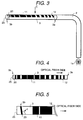
- FIG.5 is an enlarged view showing the vicinity of the other end of the light guiding rod shown in FIG.3.
- FIG.6 is an enlarged cross-sectional view showing the light guiding rod shown in FIG.3.
- FIG.7 is a view showing the whole system of a further embodiment of a lighting system in accordance with the present invention.
- FIG.8 is a top view of the light guide rod of FIG.7 seeing from the direction of an arrow D indicated in FIG.7.
- FIG.9 is an enlarged side view showing the vicinity of the other end of the light guiding rod.
- FIG.10 (a) is a partial side view of another embodiment of a light guiding rod of a lighting system in accordance with the present invention, and (b) is a cross-sectional view showing the light guiding rod.
- FIG.11 (a) is a partial side view of a further embodiment of a light guiding rod of a lighting system in accordance with the present invention, and (b) is a cross-sectional view showing the light guiding rod.
- FIG.12 (a) is a partial side view of a still further embodiment of a light guiding rod of a lighting system in accordance with the present invention, and (b) is a cross-sectional view showing the light guiding rod.
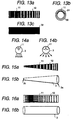
- FIG.13 (a) is a view showing a light scattering working treated pattern of a light guiding rod, (b) is a cross-sectional view of the light guiding rod, and (c) is a view showing emitted light from the light guiding rod seeing through a diffusion sheet.
- FIG.14 (a) and (b) are views explaining change in a light emitting angle when an angle ⁇ of applying a diffusion coating is varied.
- FIG. 15 (a) is a view showing a light scattering working treated pattern in a modification of a light guiding rod of a lighting system in accordance with the present invention, and (b) is a view showing the outer appearance of the light guide rod.
- FIG. 16 (a) is a view showing a light scattering working treated pattern in another modification of a light guiding rod of a lighting system in accordance with the present invention, and (b) is a view showing the outer appearance of the light guide rod.
- FIG.1 and FIG.2 are views showing an embodiment in accordance with the present invention.
- FIG.1 is a view showing the whole lighting system.
- FIG.2 is a top view of the light guide rod of FIG.1 seeing from the direction of an arrow A indicated in FIG.1.
- the reference character 1 indicates a light source such as a halogen lamp of 100W
- light of the light source 1 is transmitted to one end 3a of a light guiding rod 3, shown in right-hand side of the figure, through an optical fiber 2.
- a belt-shaped light beam is emitted from the light guiding rod 3 toward one side surface of a light guiding plate 4.
- the light incident into the light guiding plate 4 is scattered on a light scattering working treated portion 5 in a backside surface 6 and emitted from a front surface 7 of the light guiding plate 4.
- the optical fiber 2 comprises a core made of silicone rubber having a refractive index of 1.50 and a cladding made of copolymer of tetra-fluoro-ethylene and hexa-fluoro-propylene.
- the diameter of the core is 10 mm
- the thickness of the cladding is 0.5 mm
- the length of the fiber is 2 m.
- the light guiding rod 3 is a cylinder having a diameter of 10 mm and a length nearly of 500mm between the both ends 3a, 3b made of acrylic resin.
- a light scattering working treated portion 11 which is formed by applying a diffusion paint containing titanium oxide fine particles in an appropriate pattern.
- the reference character 12 indicates a portion on which the diffusion paint is not applied.
- the light guiding plate 4 is a plate made of acrylic resin having a width of 500 mm, a height of 300 mm and a thickness of 10 mm. As shown in FIG.1, in a surface of the light guiding plate 4 opposite to the front surface 7 emitting light, that is, the backside surface 6, there is provided a light scattering working treated portion 5 which is formed by applying a diffusion paint containing titanium oxide fine particles in an appropriate pattern.
- a small-size and light-weight lighting system of plane-emitting type separated from the light source can be realized by arranging the light guiding rod 3 between the light guiding plate 4 and the optical fiber 2 and by containing the light guiding plate 4 and the light guiding rod 3 in a case together.
- FIG.3 is a view showing another embodiment of a lighting system in accordance with the present invention.
- FIG.4 is a top view of the light guide rod of FIG.3 seeing from the direction of an arrow C indicated in FIG.3.
- FIG.5 is an enlarged view showing the vicinity of the other end 3b of the light guiding rod shown in FIG.3.
- a different point of the lighting system of FIG.3 from that of FIG.1 is that the light guiding plate is not provided but a reflecting portion 20 is provided in the other end 3b of the light guiding rod.
- a light guiding plate may be arranged in the same way as in the lighting system shown in FIG.1. In these figures, the same parts as those in the lighting system of FIG.1 are indicated by the same reference characters.
- the reference character 1a indicates a light source of a metal halide lamp of 60 W, and light of the light source 1a is transmitted to the one end 3a, right hand side end in the figure, through an optical fiber 2.
- the reference character 25 indicates a reflecting plate fixing plate.
- the optical fiber 2 comprises a core made of silicone rubber and a cladding made of copolymer of tetra-fluoro-ethylene and hexa-fluoro-propylene.
- the diameter of the core is 10 mm
- the thickness of the cladding is 0.5 mm
- the length of the fiber is 2 m.
- a light scattering working treated portion 11 which is formed by applying a diffusion paint containing titanium oxide fine particles in a pattern composed of rectangles.
- the area ratio applied with the diffusion paint becomes large as the distance from the one end 3a of the light guiding rod 3 increases.
- the area ratio applied with the diffusion paint of the light scattering working treated portion 11 near the other end 3b, that is, left hand side end in the figure, of the light guiding rod 3 is small in taking light reflection from the other end surface into consideration.
- the end surface of the other end 3b the light guiding rod 3 is not perpendicular to the longitudinal direction of the light guiding rod 3 but inclined with an inclining angle ⁇ of 93° , as shown in FIG.5.
- a light reflecting portion 20 which is a PET (polyethylene-terephthalate) film having a thickness of 0.1 mm vapor-deposited with silver.
- the light guiding rod 3 is a cylinder having a diameter of nearly 10 mm and a length of nearly 300 mm made of acrylic resin having a refractive index of 1.49.
- the outer periphery of the light guiding rod 3 is applied with a refracting index matching oil 21 of silicone oil having a refracting index of 1.50 to prevent degradation of light emission due to very small flaws on the surface of the light guiding rod 3 made of acrylic resin.
- a heat shrinking tube 22 made of copolymer of tetra-fluoro-ethylene and hexa-fluoro-propylene covers the outer periphery of the refractive index matching oil 21 to protect the refractive index matching oil 21 and the light guiding rod 3, as shown in FIG.6 which is an enlarged cross-sectional view of the light guiding rod shown in FIG.3.
- an intensity of the light incident into the light guiding rod 3 is gradually attenuated from the one end 3a toward the other end 3b.
- an intensity of the belt-shaped light emitted from the light emitting surface of the light guiding rod 3 becomes uniform since the light scattering working treated portion 11 has the pattern of which the area ratio becomes larger from the one end 3a of the light guiding rod toward the other end 3b and consequently an intensity of light scattered or reflected by the light scattering working treated portion 11 is increased from the one end 3a of the light guiding rod toward the other end 3b.
- a small-size and light-weight lighting system of line-emitting type separated from the light source can be realized.
- FIG.7 is a view showing an embodiment of a lighting system in accordance with the present invention.
- FIG.8 is a view of the light guide rod of FIG.7 seeing from the direction of an arrow D indicated in FIG.7.
- the same parts as those in the lighting system of FIG.3 are indicated by the same reference characters.
- a different point of the lighting system of FIG.7 from that of FIG.3 is that A side surface reflecting mirror 23 as a reflecting plate is provided in the side surface in the backside of the light guiding rod and a diffusion member 24 is provided in the front surface of the light guiding rod 3.
- a diffusion member 24 is provided in the front surface of the light guiding rod 3.
- a film 26 having vapor-deposited silver is provided through a reflecting plate fixing plate 25.
- the side surface reflecting mirror 23 is arranged so as to wrap, the side surface except for a light emitting surface from the reflecting plate fixing plate 25 to the one end 2a of the light guiding rod 3.
- a diffusion member 24 made of an acrylic milky white plate (Sumipex 030 opal; a trade mark of Sumitomo Chemical Campany Limited) having a thickness of 2 mm is provided in order to reduce unevenness in emitted light due to the pattern in the light scattering working treated portion 11 on the backside surface of the light guiding rod 3.
- This embodiment is the lighting system of Embodiment 1 in which the inclining angle ⁇ of the end surface in the other end 3b of the light guiding rod 3 is set to 95° .
- This embodiment is the lighting system of Embodiment 1 in which the end surface in the other end 3b of the light guiding rod 3 is formed in a convex curved surface having a radius R of 50 mm, as shown in FIG.9.
- FIG. 9 is an enlarged side view of the vicinity of the other end of the light guiding rod.
- This embodiment is the lighting system of Embodiment 1 in which the refractive index n m of the refractive matching oil 21 in the light guiding rod 3 is set to 1.52.
- This embodiment is the lighting system of Embodiment 1 in which the refractive index n m of the refractive matching oil 21 in the light guiding rod 3 is set to 1.40.
- This embodiment is the lighting system of Embodiment 1 in which a type A tape is used in the light scattering working treated portion of the light guiding rod 3 and the refractive index of the adhesive is to 1.50.
- This embodiment is the lighting system of Embodiment 1 in which a type A tape is used in the light scattering working treated portion of the light guiding rod 3 and the refractive index of the adhesive is to 1.53.
- This embodiment is the lighting system of Embodiment 1 in which a type B tape is used in the light scattering working treated portion of the light guiding rod 3 and the refractive index of the adhesive is to 1.50.
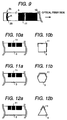
- This embodiment is the lighting system of Embodiment 1 in which the cross-sectional shape of the light guiding rod 3 is a square having a side length of 9 mm, as shown in FIG.10.
- FIG.10 (a) is a partial side view of the light guiding rod
- FIG.10 (b) is a cross-sectional view showing the light guiding rod.
- This embodiment is the lighting system of Embodiment 1 in which the cross-sectional shape of the light guiding rod 3 is an equilateral hexagon having a side length of 5 mm, as shown in FIG.11.
- FIG.11 (a) is a partial side view of the light guiding rod
- FIG.11 (b) is a cross-sectional view showing the light guiding rod.
- This example is the lighting system of Embodiment 1 in which the inclining angle ⁇ of the end surface in the other end 3b of the light guiding rod 3 is set to 90° .
- This example is the lighting system of Embodiment 1 in which the inclining angle ⁇ of the end surface in the other end 3b of the light guiding rod 3 is set to 100° .
- This example is the lighting system of Embodiment 1 in which the refractive index n m of the refractive matching oil 21 in the light guiding rod 3 is set to 1.59.
- This example is the lighting system of Embodiment 1 in which the refractive matching oil 21 is not applied to the light guiding rod 3.
- This example is the lighting system of Embodiment 1 in which a type A tape is used in the light scattering working treated portion of the light guiding rod 3 and the refractive index of the adhesive is to 1.39.
- This example is the lighting system of Embodiment 1 in which a type A tape is used in the light scattering working treated portion of the light guiding rod 3 and the refractive index of the adhesive is to 1.60.
- FIG.12 (a) is a partial side view of the light guiding rod
- FIG.12 (b) is a cross-sectional view showing the light guiding rod.
- Table 1 shows cases in which the inclining angle ⁇ and the shape of the end surface in the other end 3b of the light guiding rod 3 are varied.
- the average brightness was measured under the same condition as in Embodiment 1 except for the inclining angle ⁇ and the shape of the end surface.
- Table 2 shows cases in which the refractive index of the refractive index matching oil 21 is varied.
- Table 3 shows cases in which the kind and the refractive index of the light scattering working treated portion provided on the backside surface of the light emitting surface of the light guiding rod 3.
- Table 4 shows cases in which the shape of the light guided rod 3 is varied.
- the inclining angle ⁇ and the shape of the end surface in the other end 3b of the light guiding rod 3 is preferably set to an angle with in a range not smaller than 91° and not larger than 100°
- the refractive index n of the refractive index matching oil 21 is preferably selected so as to satisfy the relation (1)
- the refractive index of the adhesive tape is preferably selected so as to satisfy the relation (2)
- the cross-sectional shape of the light guiding rod 3 is preferably formed in a polygon having number of angles not less than four or in a circle.
- the present invention it is possible to provide a small-size and light-weight lighting system of line-emitting type which is easy in handling and is excellent in safety.
- the lighting system can be also used as a back light source of edge light type.
- the light scattering working treated portion 11 is formed in the light guiding rod 3 in a form that the area ratio of the light scattering working treated portion is increased from the one end 3a toward the other end 3b.
- the intensity ratio of emitted light in the side surface of the light guiding rod 3 can be made uniform.
- the lighting system is used as an alternative of a lamp such as a fluorescent lamp, the lighting system is not a perfect line-emitting lighting system since the pattern of the light emitting portion, that is, portions not applied with the light scattering working treatment 11 is directly brightened, as shown in FIG.13 (a).
- FIG.13 (a) is a view showing a pattern of light scattering working treatment of the light guiding rod.
- the inventors of the present invention proposed a modification in order to solve the imperfect light emitting state of the light guiding rod 3.
- a diffusion sheet 30 is attached on the outer periphery of the light guiding rod 3
- diffusion of light is caused in the interface between the diffusion sheet 30 and the light emitting portion when the diffusion sheet 30 is directly attached on the outer periphery of the light guiding rod 3 and consequently light is scattered toward unnecessary directions to cause light loss. Therefore, the light guiding rod 3 is coated with a cladding 31 and the outer periphery of the cladding 31 is coated with a diffusion sheet 30, as shown in FIG.13 (b).
- FIG.13 (b) is a cross-sectional view of the light guiding rod
- FIG.13 (c) is a view showing emitted light 32 out of the light guiding rod when it seen through the diffusion sheet.
- the best cross-sectional shape of the light guiding rod 3 is a circle or an ellipse.
- the reason is that light emitting angle can be easily adjusted by varying the applying angle ⁇ , shown in FIG.14 (a), (b), of the diffusion paint for the light scattering working treated portion 11.
- FIG.14 (a) and (b) are views explaining change in the light emitting angle when the applying angle ⁇ is varied.
- the light guiding rod 3 when the light guiding rod 3 is very long, the area of the light scattering working treated portion 11 must be decreased in order to transmit light up to a position far from the one end 3a of the light guiding rod 3. Therefore, it is necessary to make the applying angle ⁇ small. Accordingly, the light emitting angle is limited to a small value, and in order to make the emitting angle large some modifications such as employing a lens system are required and the lighting system is made complex.
- a light guiding rod having a polygon cross-section when a light guiding rod having a polygon cross-section is employed, light can be transmitted up to a position far from the one end 3a of the light guiding rod 3 though the emitting angle is determined to some extent depending on the shape of the polygon.
- the other method is that the light guiding rod 3 is formed in a tapered shape in which the cross-sectional area decreases from the one end 3a toward the other end 3b.
- the light guiding rod is formed in the tapered shape, all the light can be utilized as the belt-shaped light emitted out of the side surface without using any reflecting member, as shown in FIG.15.
- FIG.15 (a) is a view showing a light scattering working treated pattern in a modification of a light guiding rod of a lighting system in accordance with the present invention, and (b) is a view showing the outer appearance of the light guide rod.
- the optical fiber is not limited to the resin optical fiber, but a glass bundle fiber may be used as far as it can efficiently take in light from the light source.
- the shape of the light guiding rod is not limited to a circular cylinder, but an elliptic cylinder, a rectangular prism, a pentagonal prism may be used. Materials usable for the light guiding rod are polycarbonate resin, silicone resin, glass and so on.
- a shape of applying the diffusion paint may be circular or elliptical as Modification 4 shown in FIG.16, other than rectangular. Further, the shape of applying the diffusion paint may be polygonal.
- FIG. 16 (a) is a view showing a light scattering working treated pattern in another modification of a light guiding rod of a lighting system in accordance with the present invention
- (b) is a view showing the outer appearance of the light guide rod.
- the present invention has the following excellent effect.
Abstract
A small-size and light-weight lighting system of plane- or line-emitting type is provided.
In a lighting system in which light is let in from one side surface of a light guiding plate (4) and emitted from all over a front surface (7) thereof, a small-size and light-weight lighting system of plane-emitting type can be obtained by arranging a light guiding rod (3) in a position opposite to said one surface of the plate (4) and connecting the light guiding rod (3) to an optical fibre (2) coupled to a light source (1).
In a lighting system in which light is let in from one end (3a) of a light guiding rod (3) and emitted from a side surface of the rod (3) in the form of a belt-shaped line, a small-size and light-weight lighting system of line-emitting type can be obtained by providing a light scattering working treated portion (11) having a pattern the area ratio of which increases with increasing distance from said one rod end (3a), the pattern being provided on a side surface of the rod (3) in the side opposite the light emitting surface, and providing a light reflecting portion (20) in the other rod end (3b).
Description
- The present invention relates to a lighting system, and more particularly relates to a lighting system using a light guiding rod.
- Use of thin plane-emitting lighting systems is growing widely in various fields as a back-light for a liquid crystal display, an interior light in a room, a signboard and various kinds of indicating lights. These systems have a construction that a belt-shaped light source such as a fluorescent light tube is arranged on a side surface, that is, an edge of a light diffusion plate called as a light guiding plate to emit light from the front surface of the light guiding plate.
- The conventional system requires various kinds of considerations such as dissipation of heat generated by the fluorescent light tube, mechanical protection of the fluorescent tube and so on. Especially, the conventional lighting system using a high-intensity light source having a large heat generation is liable to cause breakage and accordingly requires mechanical protection. Further, the conventional lighting system cannot be used in a place where electric power is not recommended to be used or requires explosion-proof.
- Therefore, a method is being studied in which light from a light source is guided to a side surface of a light guiding plate using a large number of optical fibers.
- However, the above-mentioned method using a large number of optical fibers requires a considerably complex construction that the large number of optical fibers are integrated in a bundle in the light source side and, in the light guiding plate side, the fibers are independently separated and distributed along the side surface of the light guiding plate.
- Thereby, the conventional method using the large number of optical fibers has a disadvantage as following.
- (1) The construction of the optical fiber cables becomes complex, and connection of the optical fiber cable to the light source and the light guiding plate also becomes complex, which results in high cost.
- (2) The lighting system becomes large in size and heavy in weight since there is required a space for introducing the optical fiber cables around a connection portion between the light guiding plate and the optical fiber cables with taking bend of the optical cables into consideration. Further, it is not preferable from the aspect of appearance that a surface of the lighting system other than the light emitting surface becomes large.
- An object of the present invention is to solve the above-mentioned problems and to provide a lighting system of plane light emission type or line light emission type which is small in size and light in weight.
- The object of the present invention can be attained by providing a lighting system in which light incident into one end of a light guiding rod through an optical fiber connected to a light source is guided to a light reflecting means to emit light from the light reflecting portion, wherein the light guiding rod comprises a light scattering working treated portion being provided on a side surface of the light guiding rod and having a pattern of which the area ratio becomes large as the distance from the one end of the light guiding rod increases.
- According to another characteristic of the present invention, the light reflecting means comprises a light guiding plate which receives light at a side surface of the light guiding plate facing the light guiding rod and emits the light from the front surface of the light guiding plate in a form of plane-shape.
- According to a further characteristic of the present invention, the light reflecting means comprises a light reflecting portion which is provided on the other end of the light guiding rod and emits the light incident into the one end of the light guiding rod from a side surface of the light rod in a form of a belt-shaped line.
- As an optical fiber used in the present invention, a synthesized resin is the most suitable from the viewpoint of flexibility, light weight and handling. It is also necessary to select a material having a high heat resistance in taking temperature rise by heat generation of a light source. As a synthesized resin optical fiber satisfying these conditions, the core is preferably made of a silicone resin having a high heat resistance and a high flexibility, and the cladding is made preferably of a fluoride resin having a low refractive index and a high heat resistance such as poly-tetra-fluoro-ethylene, copolymer of tetra-fluoro-ethylene and hexa-fluoro-ethylene, copolymer of ethylene and tetra-fluoro-ethylene or copolymer of tetra-fluoro-ethylene and vinylidene fluoride.
- Although there are a single-core optical fiber and a multi-core optical fiber, the single-core optical fiber is preferable from the viewpoint of light intake efficiency from a light source and coupling efficiency to a light guiding rod, and it is also preferable that the core has a large diameter. From the above reason, it is preferable that the diameter of the core is not smaller than 2 mm and not larger than 30 mm.
- That is, there arises a problem in that the light intake efficiency becomes low when the diameter of the core is smaller than 2 mm, and the optical fiber becomes too hard to handle when the diameter is larger than 30 mm.
- Further, in the present invention, it is preferable that a light scattering working treated portion for radiating light from the front surface of the light guiding plate by scattering the light incident through the one side surface of the light guiding plate toward the front surface of the light guiding plate is provided in the backside surface of the light guiding plate. The material for the light guiding rod is not limited to a particular material as far as it has a high transparency, and a light guiding rod made of a glass or a resin can be considered as a candidate. A light guiding rod made of a glass has a higher light transmissivity compared to a resin light guiding rod and is effective when the light guiding rod is long. A light guiding rod made of a resin is effective in light weight, workability and easiness of handling. The preferable resins used for the light guiding rod are acrylic resin, polycarbonate resin and polystyrene resin which are excellent in light transmissivity and capability of mass production. Further, it is preferable from the viewpoint of space saving to let the incident light in the light guiding rod through one end of the light guiding rod, but it is possible to let in the light through the both ends of the light guiding rod.
- Further, in the present invention, it is preferable that a light scattering working treated portion for radiating light from the front surface of the light guiding plate by scattering the light incident through the one side surface of the light guiding plate toward the front surface of the light guiding plate is provided in the backside surface of the light guiding plate. The light guiding plate is not limited as far as it is a transparent plate, but the preferable materials are synthesized resins having a high transmissivity such as acrylic resin, polycarbonate resin and polystyrene resin from the viewpoint of molding capability and easiness of post-working. It is preferable from the viewpoint of easiness of working that the shape of the light guiding plate is a flat plate, but a curved plate may be acceptable from the viewpoint of lighting and design. Further, it is preferable from the viewpoint of space-saving to let the incident light in the light guiding plate through one side surface of the light guiding plate, but it is possible to let in the light through the two side surfaces, three side surfaces or four side surfaces, that is, all of the side surfaces of the light guiding plate depending on a situation. Furthermore, the front surface of the light guiding plate may be covered with a light diffusion film so that the pattern of the light scattering working treated portion is not seen from the front surface side of the light guiding plate, and also may be covered with a light focusing film having a lens function. In addition to these, the backside surface of the light guiding plate may be covered with a light reflecting member, if necessary.
- A light scattering working treated portion provided in the light guiding rod or the light guiding plate has an appropriate pattern formed by applying a diffusion paint or cutting flaws. Thereby, light incident into the light guiding rod or the light guiding plate is diffused by the light scattering working treated portion to be emitted in the direction perpendicular to the incident light direction, that is, emitted from the front surface of the light guiding plate or the side surface of the light guiding rod in the side of the light emitting plate.
- In order to attain the above object of the present invention, it is provided a lighting system in which light is let in from one end of a light guiding rod and emitted from a side surface of said light guiding rod in a form of a belt-shaped line, which further comprises a light scattering working treated portion having a pattern of which the area ratio becomes large as the distance from the one end of the light guiding rod increases, the pattern being provided on a surface of the light guiding rod in the reverse side of the light emitting surface; and a light reflecting portion provided in the other end of the light guiding rod. In this case, although an intensity of the light incident into the light guiding rod is attenuated from the one end toward the other end, an intensity of the belt-shaped light emitted from the light emitting surface of the light guiding rod becomes uniform since the light scattering working treated portion has the pattern of which the area ratio becomes larger from the one end of the light guiding rod toward the other end and consequently an intensity of light scattered or reflected by the light scattering working treated portion is increased from the one end of the light guiding rod toward the other end. Further, in this case, the reflecting portion is preferably a reflecting mirror or a diffusion reflecting plate.
- In the present invention, a refractive index matching oil having a refractive index approximately equal to a refractive index of the light guiding rod may be applied on the surface of the light guiding rod. In this case, even if there are very small flaws on the surface of the light guiding rod, degradation in light emitting characteristic can be prevented since the flaws are evened and scattering of light on the light emitting surface is prevented.
- In the present invention, the refractive index nm of the refractive index matching oil and the refractive index n0 of the light guiding rod may satisfy the following relation (1):

- In the present invention, the end surface in the other end of the light guiding rod may be an inclining flat surface.
- In the present invention, it is preferable that an angle θ of the inclining surface is not smaller than 91° and not larger than 100° . When the inclining angle is smaller than 91° , particularly smaller than 90° , it is easy to perform working of the end surface. However, an amount of light turning back to the optical fiber becomes large. On the other hand, when the inclining angle is larger than 100° , light emission only near the other end portion of the light guiding rod becomes large and accordingly unevenness appears in the light emission.
- In the present invention, the end surface in the other end of said light guiding rod may be a convex surface.
- In the present invention, it is preferable from the view point of working that the pattern of said light scattering working treated portion is of rectangles.
- Therein, as the diffusion material, a paint type diffusion material is easy to be handled. The preferable materials for the light guiding rod are synthesized resins having a transmissivity, particularly acrylic resin is preferable from the viewpoint of high transmissivity, molding capability and low cost.
- In the present invention, it is preferable that the distribution of the area ratio in the pattern occupied by the diffusion paint or the cut-flaws of the light scattering working treated portion is determined so that the brightness of the light emitting surface of the light guiding rod becomes uniform in the longitudinal direction.
- In the present invention, the light diffusion working treated portion may be formed using an adhesive tape applied with a diffusion paint or an adhesive tape made of a diffusion resin film.
- In the present invention, it is preferable that the refractive index nt of the adhesive used in the adhesive tape and the refractive index n0 of the light guiding rod satisfy the following relation (2):

- When the refractive index nt of the adhesive is out of the range expressed by the above relation (2), intensity of the emitted light is decreased.
- In the present invention, a translucent milky white diffusion member may be arranged in front of the light emitting surface of the light guiding rod.
- In the present invention, the outer periphery of the light guiding rod may be coated with a cladding layer made of a transparent resin and the outer periphery of the cladding layer may be coated with a light diffusion sheet. Further, in order to mechanically protect the light guiding rod or to protect the refractive index matching oil layer, the periphery of the light guiding rod may be coated with a transparent resin tube.
- It is preferable that the transparent resin tube is a transparent heat shrinking tube to keep adherence after coating. Preferable materials for the transparent resin tube are polyethylene, copolymer of ethylene-vinyl-acetate, copolymer of tetra-fluoro-ethylene and hexa-fluoro-propylene, and copolymer of tetra-fluoro-ethylene and perfluoro-alkyl ether which have a high transmissivity and a high adhesive capability.
- It is preferable that the optical fiber is of a single-core synthetic resin core and has a core diameter not smaller than 3 mm and not larger than 30 mm. A bundle fiber made of glass is high in cost, and a light intensity sufficient for a belt-shaped light emission body cannot obtained when the diameter of the core is smaller than 3 mm, and the synthetic resin optical fiber becomes too hard to handle when the diameter is larger than 30 mm.
- In the present invention, the cross-sectional shape of the light guiding rod may be circular or elliptic.
- In the present invention, the cross-sectional shape of the light guiding rod may be polygonal. Especially, it is preferable that the shape of the light guiding rod is a polygonal prism of which number of angles is not less than four. A triangle prism cannot provide a light guiding rod having an excellent light emission intensity characteristic.
- In the present invention, the shape of the light guiding rod may be thin and tapered from one end to the other end.
- FIG.1 is a view showing the whole system of an embodiment of a lighting system in accordance with the present invention.
- FIG.2 is a top view of the light guide rod of FIG.1 seeing from the direction of an arrow A indicated in FIG.1.
- FIG.3 is a view showing the whole system of another embodiment of a lighting system in accordance with the present invention.
- FIG.4 is a top view of the light guide rod of FIG.3 seeing from the direction of an arrow C indicated in FIG.3.
- FIG.5 is an enlarged view showing the vicinity of the other end of the light guiding rod shown in FIG.3.
- FIG.6 is an enlarged cross-sectional view showing the light guiding rod shown in FIG.3.
- FIG.7 is a view showing the whole system of a further embodiment of a lighting system in accordance with the present invention.
- FIG.8 is a top view of the light guide rod of FIG.7 seeing from the direction of an arrow D indicated in FIG.7.
- FIG.9 is an enlarged side view showing the vicinity of the other end of the light guiding rod.
- FIG.10 (a) is a partial side view of another embodiment of a light guiding rod of a lighting system in accordance with the present invention, and (b) is a cross-sectional view showing the light guiding rod.
- FIG.11 (a) is a partial side view of a further embodiment of a light guiding rod of a lighting system in accordance with the present invention, and (b) is a cross-sectional view showing the light guiding rod.
- FIG.12 (a) is a partial side view of a still further embodiment of a light guiding rod of a lighting system in accordance with the present invention, and (b) is a cross-sectional view showing the light guiding rod.
- FIG.13 (a) is a view showing a light scattering working treated pattern of a light guiding rod, (b) is a cross-sectional view of the light guiding rod, and (c) is a view showing emitted light from the light guiding rod seeing through a diffusion sheet.
- FIG.14 (a) and (b) are views explaining change in a light emitting angle when an angle α of applying a diffusion coating is varied.
- FIG. 15 (a) is a view showing a light scattering working treated pattern in a modification of a light guiding rod of a lighting system in accordance with the present invention, and (b) is a view showing the outer appearance of the light guide rod.
- FIG. 16 (a) is a view showing a light scattering working treated pattern in another modification of a light guiding rod of a lighting system in accordance with the present invention, and (b) is a view showing the outer appearance of the light guide rod.
- Embodiments of the present invention will be described in detail below, referring to the accompanying drawings.
- FIG.1 and FIG.2 are views showing an embodiment in accordance with the present invention. FIG.1 is a view showing the whole lighting system. FIG.2 is a top view of the light guide rod of FIG.1 seeing from the direction of an arrow A indicated in FIG.1.
- In FIG.1, the
reference character 1 indicates a light source such as a halogen lamp of 100W, light of thelight source 1 is transmitted to oneend 3a of alight guiding rod 3, shown in right-hand side of the figure, through anoptical fiber 2. A belt-shaped light beam is emitted from thelight guiding rod 3 toward one side surface of a light guiding plate 4. The light incident into the light guiding plate 4 is scattered on a light scattering working treatedportion 5 in abackside surface 6 and emitted from afront surface 7 of the light guiding plate 4. - The
optical fiber 2 comprises a core made of silicone rubber having a refractive index of 1.50 and a cladding made of copolymer of tetra-fluoro-ethylene and hexa-fluoro-propylene. The diameter of the core is 10 mm, the thickness of the cladding is 0.5 mm and the length of the fiber is 2 m. - The
light guiding rod 3 is a cylinder having a diameter of 10 mm and a length nearly of 500mm between the both ends 3a, 3b made of acrylic resin. As shown in FIG.2, in the backside surface of thelight guiding rod 3 opposite to the surface emitting light, that is, the light emitting surface, there is provided a light scattering working treatedportion 11 which is formed by applying a diffusion paint containing titanium oxide fine particles in an appropriate pattern. When the light from the optical fiber is irradiated onto the light scattering working treatedportion 11 made of the diffusion paint, the light is scattered on the light scattering working treatedportion 11 and emitted toward the light guiding plate 4. In FIG.2, thereference character 12 indicates a portion on which the diffusion paint is not applied. - The light guiding plate 4 is a plate made of acrylic resin having a width of 500 mm, a height of 300 mm and a thickness of 10 mm. As shown in FIG.1, in a surface of the light guiding plate 4 opposite to the
front surface 7 emitting light, that is, thebackside surface 6, there is provided a light scattering working treatedportion 5 which is formed by applying a diffusion paint containing titanium oxide fine particles in an appropriate pattern. - As described above, according to the present invention, a small-size and light-weight lighting system of plane-emitting type separated from the light source can be realized by arranging the
light guiding rod 3 between the light guiding plate 4 and theoptical fiber 2 and by containing the light guiding plate 4 and thelight guiding rod 3 in a case together. - FIG.3 is a view showing another embodiment of a lighting system in accordance with the present invention. FIG.4 is a top view of the light guide rod of FIG.3 seeing from the direction of an arrow C indicated in FIG.3. FIG.5 is an enlarged view showing the vicinity of the
other end 3b of the light guiding rod shown in FIG.3. - A different point of the lighting system of FIG.3 from that of FIG.1 is that the light guiding plate is not provided but a reflecting
portion 20 is provided in theother end 3b of the light guiding rod. However, a light guiding plate may be arranged in the same way as in the lighting system shown in FIG.1. In these figures, the same parts as those in the lighting system of FIG.1 are indicated by the same reference characters. - Referring to FIG.3, the
reference character 1a indicates a light source of a metal halide lamp of 60 W, and light of thelight source 1a is transmitted to the oneend 3a, right hand side end in the figure, through anoptical fiber 2. Thereference character 25 indicates a reflecting plate fixing plate. Theoptical fiber 2 comprises a core made of silicone rubber and a cladding made of copolymer of tetra-fluoro-ethylene and hexa-fluoro-propylene. The diameter of the core is 10 mm, the thickness of the cladding is 0.5 mm and the length of the fiber is 2 m. - As shown in FIG.4, in the backside surface of the
light guiding rod 3 opposite to the surface emitting light, that is, the reverse side of the page of the figure, there is provided a light scattering working treatedportion 11 which is formed by applying a diffusion paint containing titanium oxide fine particles in a pattern composed of rectangles. The area ratio applied with the diffusion paint becomes large as the distance from the oneend 3a of thelight guiding rod 3 increases. However, the area ratio applied with the diffusion paint of the light scattering working treatedportion 11 near theother end 3b, that is, left hand side end in the figure, of thelight guiding rod 3 is small in taking light reflection from the other end surface into consideration. The end surface of theother end 3b thelight guiding rod 3 is not perpendicular to the longitudinal direction of thelight guiding rod 3 but inclined with an inclining angle θ of 93° , as shown in FIG.5. - On the end surface in the
other end 3b of thelight guiding rod 3, there is provided alight reflecting portion 20 which is a PET (polyethylene-terephthalate) film having a thickness of 0.1 mm vapor-deposited with silver. Thelight guiding rod 3 is a cylinder having a diameter of nearly 10 mm and a length of nearly 300 mm made of acrylic resin having a refractive index of 1.49. The outer periphery of thelight guiding rod 3 is applied with a refractingindex matching oil 21 of silicone oil having a refracting index of 1.50 to prevent degradation of light emission due to very small flaws on the surface of thelight guiding rod 3 made of acrylic resin. aheat shrinking tube 22 made of copolymer of tetra-fluoro-ethylene and hexa-fluoro-propylene covers the outer periphery of the refractiveindex matching oil 21 to protect the refractiveindex matching oil 21 and thelight guiding rod 3, as shown in FIG.6 which is an enlarged cross-sectional view of the light guiding rod shown in FIG.3. - When light is let in from the
optical fiber 2 into theother end 3b of thelight guiding rod 3, an intensity of the light incident into thelight guiding rod 3 is gradually attenuated from the oneend 3a toward theother end 3b. However, an intensity of the belt-shaped light emitted from the light emitting surface of thelight guiding rod 3 becomes uniform since the light scattering working treatedportion 11 has the pattern of which the area ratio becomes larger from the oneend 3a of the light guiding rod toward theother end 3b and consequently an intensity of light scattered or reflected by the light scattering working treatedportion 11 is increased from the oneend 3a of the light guiding rod toward theother end 3b. - As described above, according to the present invention, a small-size and light-weight lighting system of line-emitting type separated from the light source can be realized.
- FIG.7 is a view showing an embodiment of a lighting system in accordance with the present invention. FIG.8 is a view of the light guide rod of FIG.7 seeing from the direction of an arrow D indicated in FIG.7. In these figures, the same parts as those in the lighting system of FIG.3 are indicated by the same reference characters.
- A different point of the lighting system of FIG.7 from that of FIG.3 is that A side
surface reflecting mirror 23 as a reflecting plate is provided in the side surface in the backside of the light guiding rod and adiffusion member 24 is provided in the front surface of thelight guiding rod 3. However, it is possible to arrange the light guiding plate of FIG.1 instead of thediffusion member 24. - In the end surface of the
other end 3b of thelight guiding rod 3, afilm 26 having vapor-deposited silver is provided through a reflectingplate fixing plate 25. The sidesurface reflecting mirror 23 is arranged so as to wrap, the side surface except for a light emitting surface from the reflectingplate fixing plate 25 to the one end 2a of thelight guiding rod 3. In the front surface of the light emitting surface of thelight guiding rod 3, adiffusion member 24 made of an acrylic milky white plate (Sumipex 030 opal; a trade mark of Sumitomo Chemical Campany Limited) having a thickness of 2 mm is provided in order to reduce unevenness in emitted light due to the pattern in the light scattering working treatedportion 11 on the backside surface of thelight guiding rod 3. - When light was let in the one
end 3a of thelight guiding rod 3, an average brightness on thediffusion member 24 was 6500 cd/m. - This embodiment is the lighting system of
Embodiment 1 in which the inclining angle θ of the end surface in theother end 3b of thelight guiding rod 3 is set to 95° . - This embodiment is the lighting system of
Embodiment 1 in which the end surface in theother end 3b of thelight guiding rod 3 is formed in a convex curved surface having a radius R of 50 mm, as shown in FIG.9. FIG. 9 is an enlarged side view of the vicinity of the other end of the light guiding rod. - This embodiment is the lighting system of
Embodiment 1 in which the refractive index nm of the refractive matchingoil 21 in thelight guiding rod 3 is set to 1.52. - This embodiment is the lighting system of
Embodiment 1 in which the refractive index nm of the refractive matchingoil 21 in thelight guiding rod 3 is set to 1.40. - This embodiment is the lighting system of
Embodiment 1 in which a type A tape is used in the light scattering working treated portion of thelight guiding rod 3 and the refractive index of the adhesive is to 1.50. - This embodiment is the lighting system of
Embodiment 1 in which a type A tape is used in the light scattering working treated portion of thelight guiding rod 3 and the refractive index of the adhesive is to 1.53. - This embodiment is the lighting system of
Embodiment 1 in which a type B tape is used in the light scattering working treated portion of thelight guiding rod 3 and the refractive index of the adhesive is to 1.50. - This embodiment is the lighting system of
Embodiment 1 in which the cross-sectional shape of thelight guiding rod 3 is a square having a side length of 9 mm, as shown in FIG.10. FIG.10 (a) is a partial side view of the light guiding rod, and FIG.10 (b) is a cross-sectional view showing the light guiding rod. - This embodiment is the lighting system of
Embodiment 1 in which the cross-sectional shape of thelight guiding rod 3 is an equilateral hexagon having a side length of 5 mm, as shown in FIG.11. FIG.11 (a) is a partial side view of the light guiding rod, and FIG.11 (b) is a cross-sectional view showing the light guiding rod. - This example is the lighting system of
Embodiment 1 in which the inclining angle θ of the end surface in theother end 3b of thelight guiding rod 3 is set to 90° . - This example is the lighting system of
Embodiment 1 in which the inclining angle θ of the end surface in theother end 3b of thelight guiding rod 3 is set to 100° . - This example is the lighting system of
Embodiment 1 in which the refractive index nm of the refractive matchingoil 21 in thelight guiding rod 3 is set to 1.59. - This example is the lighting system of
Embodiment 1 in which the refractive matchingoil 21 is not applied to thelight guiding rod 3. - This example is the lighting system of
Embodiment 1 in which a type A tape is used in the light scattering working treated portion of thelight guiding rod 3 and the refractive index of the adhesive is to 1.39. - This example is the lighting system of
Embodiment 1 in which a type A tape is used in the light scattering working treated portion of thelight guiding rod 3 and the refractive index of the adhesive is to 1.60. - This example is the lighting system of
Embodiment 1 in which the cross-sectional shape of thelight guiding rod 3 is an equilateral triangle having a side length of 13 mm, as shown in FIG.12. FIG.12 (a) is a partial side view of the light guiding rod, and FIG.12 (b) is a cross-sectional view showing the light guiding rod. - The above-mentioned
embodiments 1 to 10 and the above-mentioned comparative examples 1 to 7 are summarized in Table 1 to Table 4.Table 1 ITEM STATE OF END SURFACE AVERAGE BRIGHTNESS (cd/cm2) EMBODIMENT 1θ=93° 6500 EMBODIMENT 2θ=95° 5700 COMPARATIVE EXAMPLE 1 θ=90° 4800 COMPARATIVE EXAMPLE 2 θ=105° 2200 EMBODIMENT 3convex surface R=50 6300 R: radius of curvature (mm) Table 2 ITEM REFRACTIVE INDEX OF REFRACTIVE MATCHING OIL AVERAGE BRIGHTNESS (cd/cm2) EMBODIMENT 11.50 6500 EMBODIMENT 4 1.52 6000 EMBODIMENT 51.40 4000 COMPARATIVE EXAMPLE 3 1.59 4300 COMPARATIVE EXAMPLE 4 without oil 3000 refractive index of light guiding rod n0=1.49 Table 3 ITEM KIND OF TAPE REFRACTIVE INDEX OF ADHESIVE AVERAGE BRIGHTNESS (cd/cm2) EMBODIMENT 6TYPE A 1.50 5800 EMBODIMENT 7TYPE A 1.53 5500 EMBODIMENT 8 TYPE B 1.50 5200 COMP.EXAMPLE 5 TYPE A 1.39 4100 COMP.EXAMPLE 6 TYPE A 1.60 3900 refractive index of light guiding rod n0=1.49
TYPE A: PET film containing titanium oxide of 1 wt% having a thickness of 0.1 mm and adhesive
TYPE B: PET film having a thickness of 0.1 mm applied with the diffusion paint ofEmbodiment 1 and adhesive on the surface opposite to the diffusion paint applied surfaceTable 4 ITEM SHAPE OF LIGHT GUIDING ROD AVERAGE BRIGHTNESS (cd/cm2) EMBODIMENT 110 mm⌀ 6500 EMBODIMENT 9 square, 9 mm side 5000 EMBODIMENT 10 equilateral hexagon, 5mm side 5200 COMPARATIVE EXAMPLE 7 equilateral triangle, 13 mm side 2000 - Table 1 shows cases in which the inclining angle θ and the shape of the end surface in the
other end 3b of thelight guiding rod 3 are varied. The average brightness was measured under the same condition as inEmbodiment 1 except for the inclining angle θ and the shape of the end surface. - Table 2 shows cases in which the refractive index of the refractive
index matching oil 21 is varied. - Table 3 shows cases in which the kind and the refractive index of the light scattering working treated portion provided on the backside surface of the light emitting surface of the
light guiding rod 3. - Table 4 shows cases in which the shape of the light guided
rod 3 is varied. - It can be understood from Table 1 to Table 4 that the inclining angle θ and the shape of the end surface in the
other end 3b of thelight guiding rod 3 is preferably set to an angle with in a range not smaller than 91° and not larger than 100°, the refractive index n of the refractiveindex matching oil 21 is preferably selected so as to satisfy the relation (1), the refractive index of the adhesive tape is preferably selected so as to satisfy the relation (2), and the cross-sectional shape of thelight guiding rod 3 is preferably formed in a polygon having number of angles not less than four or in a circle. - As described above, according to the present invention, it is possible to provide a small-size and light-weight lighting system of line-emitting type which is easy in handling and is excellent in safety. The lighting system can be also used as a back light source of edge light type.
- As shown in FIG.2 and FIG. 4, the light scattering working treated
portion 11 is formed in thelight guiding rod 3 in a form that the area ratio of the light scattering working treated portion is increased from the oneend 3a toward theother end 3b. By this configuration, the intensity ratio of emitted light in the side surface of thelight guiding rod 3 can be made uniform. However, when the lighting system is used as an alternative of a lamp such as a fluorescent lamp, the lighting system is not a perfect line-emitting lighting system since the pattern of the light emitting portion, that is, portions not applied with the lightscattering working treatment 11 is directly brightened, as shown in FIG.13 (a). Here, FIG.13 (a) is a view showing a pattern of light scattering working treatment of the light guiding rod. - Therefore, the inventors of the present invention proposed a modification in order to solve the imperfect light emitting state of the
light guiding rod 3. - A modification of a lighting system in accordance with the present invention will be described below.
- Although it can be considered that a
diffusion sheet 30 is attached on the outer periphery of thelight guiding rod 3, diffusion of light is caused in the interface between thediffusion sheet 30 and the light emitting portion when thediffusion sheet 30 is directly attached on the outer periphery of thelight guiding rod 3 and consequently light is scattered toward unnecessary directions to cause light loss. Therefore, thelight guiding rod 3 is coated with acladding 31 and the outer periphery of thecladding 31 is coated with adiffusion sheet 30, as shown in FIG.13 (b). By doing so, only the light scattered by the light scattering working treatedportion 11 is emitted external out of thelight guiding rod 3, and passing the light through thediffusion sheet 30 makes the pattern in the light emitting portion not seen directly, as shown in FIG.13 (c). As a result, it is possible to obtain a line-emission type lighting system like a fluorescent lamp without bright spots. The material for thecladding 31 used is copolymer of tetra-fluoro-ethylene and hexa-fluoro-propylene having a refractive index of 1.34. FIG.13 (b) is a cross-sectional view of the light guiding rod, and FIG.13 (c)is a view showing emitted light 32 out of the light guiding rod when it seen through the diffusion sheet. - The best cross-sectional shape of the
light guiding rod 3 is a circle or an ellipse. The reason is that light emitting angle can be easily adjusted by varying the applying angle α , shown in FIG.14 (a), (b), of the diffusion paint for the light scattering working treatedportion 11. FIG.14 (a) and (b) are views explaining change in the light emitting angle when the applying angle α is varied. - However, when the
light guiding rod 3 is very long, the area of the light scattering working treatedportion 11 must be decreased in order to transmit light up to a position far from the oneend 3a of thelight guiding rod 3. Therefore, it is necessary to make the applying angle α small. Accordingly, the light emitting angle is limited to a small value, and in order to make the emitting angle large some modifications such as employing a lens system are required and the lighting system is made complex. When a light guiding rod having a polygon cross-section is employed, light can be transmitted up to a position far from the oneend 3a of thelight guiding rod 3 though the emitting angle is determined to some extent depending on the shape of the polygon. - There are two methods for effectively using the incident light to the
light guiding rod 3, and one is a method in which the end surface in theother end 3b of thelight guiding rod 3 is vapor-deposited with a metal to reflect light in a high efficiency or applied with a diffusion paint, as described above. - The other method is that the
light guiding rod 3 is formed in a tapered shape in which the cross-sectional area decreases from the oneend 3a toward theother end 3b. When the light guiding rod is formed in the tapered shape, all the light can be utilized as the belt-shaped light emitted out of the side surface without using any reflecting member, as shown in FIG.15. FIG.15 (a) is a view showing a light scattering working treated pattern in a modification of a light guiding rod of a lighting system in accordance with the present invention, and (b) is a view showing the outer appearance of the light guide rod. - Although the halogen lamp or the metal halide lamp is used as the light source in the embodiments described above, an LED or sun light may be used. The optical fiber is not limited to the resin optical fiber, but a glass bundle fiber may be used as far as it can efficiently take in light from the light source. The shape of the light guiding rod is not limited to a circular cylinder, but an elliptic cylinder, a rectangular prism, a pentagonal prism may be used. Materials usable for the light guiding rod are polycarbonate resin, silicone resin, glass and so on. A shape of applying the diffusion paint may be circular or elliptical as Modification 4 shown in FIG.16, other than rectangular. Further, the shape of applying the diffusion paint may be polygonal. The diffusion paint materials usable are magnesium oxide, zinc sulfide in addition to titanium oxide. The materials usable for the reflecting portion are an aluminum thin film, an aluminum foil, a stainless foil in addition to the silver thin film. Here, FIG. 16 (a) is a view showing a light scattering working treated pattern in another modification of a light guiding rod of a lighting system in accordance with the present invention, and (b) is a view showing the outer appearance of the light guide rod.
- Summarizing the above, the present invention has the following excellent effect.
- It is possible to realize a lighting system of plane light emitting type or line light emitting type which is small in size and light in weight.
Claims (20)
- A lighting system in which light incident into one end (3a) of a light guiding rod (3) through an optical fibre (2) connected to a light source (1) is guided to a light reflecting means and emitted therefrom,
wherein said light guiding rod (3) comprises a light scattering working treated portion (11) provided on a side surface of said rod (3) and having a pattern the area ratio of which increases with increasing distance from said one rod end (3a). - The lighting system of claim 1, wherein said light reflecting means comprises a light guiding plate (4) which receives light at a side surface facing said light guiding rod (3) and emits the light from a front surface (7) in a plane-shaped form.
- The lighting system of claim 2, wherein said optical fibre (2) is made of heat resistant plastics material.
- The lighting system of claim 2, wherein said light scattering working treated portion (11) of the rod (3) is provided in the side opposite said light guiding plate (4).
- The lighting system of claim 2, wherein a second light scattering working treated portion (5) is provided in a back surface of said light guiding plate (4) for emitting light from the front surface (7) of said plate (4) by scattering the light incident through said one side surface of said plate (4) toward said front surface (7).
- The lighting system of claim 4 or 5, wherein the light scattering working treated portion (5) of said plate (4) has a pattern formed by applying a diffusion paint or by cutting flaws.
- The lighting system of claim 1, wherein said light reflecting means comprises a light reflecting portion (20) which is provided on the other end (3b) of said light guiding rod (3) and emits light incident into the one rod end (3a) from a side surface of the rod (3) in the form of a belt-shaped line.
- The lighting system of claim 7, wherein a refractive index matching oil (21) having a refractive index approximately equal to that of the light guiding rod (3) is applied on the surface of said rod (3).
- The lighting system of claim 8, wherein the refractive index nm of said refractive index matching oil (21) and the refractive index n0 of said light guiding rod (3) satisfy the relation

- The lighting system of claim 7, wherein the end surface (20) in the other rod end (3b) is an inclined flat surface.
- The lighting system of claim 10, wherein an angle θ of said inclined surface (20) is not smaller than 91'' and not larger than 100''
- The lighting system of claim 7, wherein the end surface (20) in the other rod end (3b) is convex.
- The lighting system of claim 1, wherein the pattern of said light scattering working treated portion (11) is constituted by rectangles.
- The lighting system of claim 7, wherein the distribution of the area ratio in the pattern occupied by diffusion paint or cut-flaws of said light scattering working treated portion (11) is determined so that the brightness of the light emitting surface of said rod (3) becomes uniform in the longitudinal direction.
- The lighting system of claim 1, wherein said light diffusion working treated portion (11) is formed by an adhesive tape applied with a diffusion paint or made of a diffusion resin film.
- The lighting system of claim 15, wherein the refractive index nt of an adhesive used in said adhesive tape and the refractive index n0 of said light guiding rod (3) satisfy the relation

- The lighting system of claim 7, wherein a translucent milky white diffusion member (24) is arranged in front of the light emitting surface of said light guiding rod (3).
- The lighting system of claim 1, wherein the outer periphery of said light guiding rod (3) is coated with a cladding layer (31) made of a transparent resin, and the outer periphery of said cladding layer (31) is coated with a light diffusion sheet (30).
- The lighting system of claim 1, wherein the cross-sectional shape of said light guiding rod (3) is circular or elliptic or polygonal.
- The lighting system of claim 1, wherein said light guiding rod (3) is thin and tapers from one end (3a) to the other end (3b).
Applications Claiming Priority (4)
| Application Number | Priority Date | Filing Date | Title |
|---|---|---|---|
| JP8227096 | 1996-04-04 | ||
| JP82270/96 | 1996-04-04 | ||
| JP8236976A JPH09325221A (en) | 1996-04-04 | 1996-09-06 | Lighting device |
| JP236976/96 | 1996-09-06 |
Publications (1)
| Publication Number | Publication Date |
|---|---|
| EP0800036A1 true EP0800036A1 (en) | 1997-10-08 |
Family
ID=26423295
Family Applications (1)
| Application Number | Title | Priority Date | Filing Date |
|---|---|---|---|
| EP97104634A Withdrawn EP0800036A1 (en) | 1996-04-04 | 1997-03-18 | Lighting system |
Country Status (5)
| Country | Link |
|---|---|
| US (1) | US5857761A (en) |
| EP (1) | EP0800036A1 (en) |
| JP (1) | JPH09325221A (en) |
| CA (1) | CA2201795C (en) |
| TW (1) | TW430064U (en) |
Cited By (38)
| Publication number | Priority date | Publication date | Assignee | Title |
|---|---|---|---|---|
| EP0866264A1 (en) * | 1997-03-18 | 1998-09-23 | Seiko Epson Corporation | Lighting device, liquid crystal display unit, and electronic equipment |
| EP0874191A2 (en) * | 1997-04-24 | 1998-10-28 | Bridgestone Corporation | Optical transmission tube, method for making it and linear illuminant system |
| EP0895104A1 (en) * | 1997-07-14 | 1999-02-03 | Matsushita Electric Works, Ltd. | Side-face illuminating optical fiber |
| EP0899503A1 (en) * | 1997-08-22 | 1999-03-03 | Bridgestone Corporation | Line glower |
| EP0935091A1 (en) * | 1998-02-05 | 1999-08-11 | Hella KG Hueck & Co. | Rod-like lightguide |
| WO1999041543A1 (en) * | 1998-02-17 | 1999-08-19 | Ineos Acrylics Uk Limited | An edge-lit illumination system |
| WO1999046537A1 (en) * | 1998-03-13 | 1999-09-16 | Minnesota Mining And Manufacturing Company | Optical fiber linear light source |
| EP0945674A1 (en) * | 1998-03-25 | 1999-09-29 | Christophe Blanc | Luminous edge-lit device |
| EP0974785A1 (en) * | 1998-07-21 | 2000-01-26 | Combined Optical Industries Limited | Illuminator |
| FR2788105A1 (en) * | 1998-12-31 | 2000-07-07 | Jean Paul Castille | Illuminated woven surface, e.g. for garment, contains optical fibers, light source and diffuser |
| WO2000065277A1 (en) * | 1999-04-28 | 2000-11-02 | 3M Innovative Properties Company | Shallow depth back lit illuminated signage |
| WO2000077447A1 (en) * | 1999-06-15 | 2000-12-21 | Leonardo Masotti | Continuous extended optical sources and receivers and optical barriers using said sources and said receivers |
| EP1083383A1 (en) * | 1999-09-07 | 2001-03-14 | Gerhard Dipl.-Phys. Karl | Luminous body for transparent image |
| EP1104536A1 (en) * | 1998-08-20 | 2001-06-06 | Physical Optics Corporation | Fiber optic luminaire |
| US6278827B1 (en) * | 1998-04-20 | 2001-08-21 | Bridgestone Corporation | Light transmission tubes |
| WO2001071247A1 (en) * | 2000-03-16 | 2001-09-27 | 3M Innovative Properties Company | Illumination device |
| WO2001084047A1 (en) * | 2000-05-04 | 2001-11-08 | 3M Innovative Properties Company | Light pipe fixture with internal extractor |
| DE10033133A1 (en) * | 2000-07-07 | 2002-01-17 | Hella Kg Hueck & Co | Rod-shaped light guide |
| US6467922B1 (en) | 1999-12-09 | 2002-10-22 | Gc Communication | Method and apparatus for laser machining light guides, light guides obtained thereby, and back-lit screens incorporating such light guides |
| US6597834B1 (en) | 1998-03-13 | 2003-07-22 | 3M Innovative Properties Company | Optical fiber linear light source |
| US6621973B1 (en) | 2000-03-16 | 2003-09-16 | 3M Innovative Properties Company | Light guide with protective outer sleeve |
| WO2003098288A1 (en) * | 2002-05-16 | 2003-11-27 | Andrew Stanley Lasota | Illuminable display device |
| WO2003102643A1 (en) * | 2002-05-31 | 2003-12-11 | 3M Innovative Properties Company | Light guide within recessed housing |
| GB2389954A (en) * | 2002-05-16 | 2003-12-24 | Andrew Stanley Lasota | Optic Fibre Vehicle Mounted Advertisement |
| DE10318723A1 (en) * | 2003-04-25 | 2004-11-11 | Müller, Gerhard | Illuminated handrail for stair wells and parapets has massive body in two extended facing parts with light dispersing surfaces and light sources coupled along the long axis |
| WO2005059434A1 (en) * | 2003-12-17 | 2005-06-30 | Morton Graham | An illumination device |
| WO2007089729A2 (en) * | 2006-01-27 | 2007-08-09 | Megapull, Inc. | Apparatus for illuminating channel letters and light boxes |
| EP1852720A2 (en) * | 2006-04-20 | 2007-11-07 | Pyratec Produktion GmbH & Co. KG | Laminar illumination element |
| DE102008009138A1 (en) * | 2008-02-14 | 2009-08-27 | Schott Ag | Side emitting refractive index adapted fiber for use as e.g. part of headlamp of automobile, has light guiding core made of glass provided with external peripheral surface, where diffusion particles are applied on peripheral surface |
| DE102008009137A1 (en) * | 2008-02-14 | 2009-08-27 | Schott Ag | Laterally emitting step index fiber for e.g. contour illumination of ship, has scattering zone located between core and jacket, where particles are embedded in zone that includes refractive index differing from refractive index of jacket |
| DE102008009139A1 (en) * | 2008-02-14 | 2009-08-27 | Schott Ag | Laterally emitting step index fiber for e.g. contour illumination of ship, has scattering zone located between core and jacket, where particles are embedded in zone that includes refractive index differing from refractive index of jacket |
| DE102010062900A1 (en) | 2010-12-13 | 2012-06-14 | Evonik Röhm Gmbh | Process for producing light-conducting bodies and their use in lighting units |
| DE102011088835A1 (en) | 2011-12-16 | 2013-06-20 | Evonik Industries Ag | Process for producing light-conducting bodies and their use in lighting units |
| US8487315B2 (en) | 2000-04-12 | 2013-07-16 | Semiconductor Energy Laboratory Co., Ltd. | Illumination apparatus |
| US8582943B2 (en) | 2008-02-14 | 2013-11-12 | Schott Ag | Side-emitting step index fiber |
| EP2702317A1 (en) * | 2011-04-26 | 2014-03-05 | Corning Incorporated | Systems and methods for coupling light into a transparent sheet |
| US8702292B2 (en) | 2010-09-22 | 2014-04-22 | Terralux, Inc. | Linear illumination devices having light guides and LED-based illumination modules |
| EP2827186A4 (en) * | 2012-03-16 | 2015-11-11 | Boe Technology Group Co Ltd | Backlight module and display apparatus |
Families Citing this family (79)
| Publication number | Priority date | Publication date | Assignee | Title |
|---|---|---|---|---|
| AUPO053896A0 (en) * | 1996-06-17 | 1996-07-11 | Franklin, James Bruce | Improvements in natural lighting |
| JPH11119701A (en) * | 1997-10-13 | 1999-04-30 | Sanyo Electric Co Ltd | Back light |
| US6095673A (en) * | 1998-01-20 | 2000-08-01 | The Whitaker Corporation | Co-extruded light pipe |
| JP3379043B2 (en) * | 1998-06-29 | 2003-02-17 | ミネベア株式会社 | Planar lighting device |
| DE69942499D1 (en) * | 1998-10-05 | 2010-07-29 | Semiconductor Energy Lab | Reflecting semiconductor device |
| JP2001014921A (en) * | 1999-06-28 | 2001-01-19 | Minebea Co Ltd | Surface lighting system |
| US6502946B1 (en) * | 1999-07-21 | 2003-01-07 | Nippon Sheet Glass Co., Ltd. | Planar display lamp and method of forming a light scatterer pattern |
| JP2001035230A (en) * | 1999-07-26 | 2001-02-09 | Minebea Co Ltd | Flat lighting system |
| US6290713B1 (en) | 1999-08-24 | 2001-09-18 | Thomas A. Russell | Flexible illuminators for phototherapy |
| JP2001222906A (en) | 2000-02-08 | 2001-08-17 | Minebea Co Ltd | Flat lighting system |
| KR100318744B1 (en) * | 2000-02-21 | 2001-12-28 | 윤종용 | Apparatus for back lighting of LCD having an optical fiber |
| JP3555863B2 (en) * | 2000-07-06 | 2004-08-18 | Nec液晶テクノロジー株式会社 | Reflector, method of manufacturing the same, and liquid crystal display device using the same |
| US6607297B2 (en) * | 2000-10-05 | 2003-08-19 | Minebea Co., Ltd. | Spread illuminating apparatus including inclined light scattering portions |
| US6768525B2 (en) * | 2000-12-01 | 2004-07-27 | Lumileds Lighting U.S. Llc | Color isolated backlight for an LCD |
| US6418252B1 (en) * | 2001-01-16 | 2002-07-09 | The Regents Of The University Of California | Light diffusing fiber optic chamber |
| JP2002231031A (en) * | 2001-02-06 | 2002-08-16 | Enplas Corp | Flat light source device, image display device and light guide plate |
| US6896398B2 (en) * | 2001-04-27 | 2005-05-24 | Ilight Technologies, Inc. | Simulated neon illumination device using end-lit waveguide |
| KR100394170B1 (en) * | 2001-06-23 | 2003-08-09 | 송영윤 | An Lighting Device Using Cable Optics |
| US7263268B2 (en) * | 2001-07-23 | 2007-08-28 | Ben-Zion Inditsky | Ultra thin radiation management and distribution systems with hybrid optical waveguide |
| US6536933B1 (en) * | 2001-08-27 | 2003-03-25 | Palm, Inc. | Vapor deposition of reflective and/or phosphorescent material in a lighting system |
| JP2003086015A (en) * | 2001-09-07 | 2003-03-20 | Nippon Leiz Co Ltd | Light guiding body and plane surface lighting system |
| US6966684B2 (en) * | 2001-09-13 | 2005-11-22 | Gelcore, Llc | Optical wave guide |
| US6799880B2 (en) * | 2001-12-31 | 2004-10-05 | 3M Innovative Properties Company | Illumination device |
| KR100472468B1 (en) * | 2002-08-07 | 2005-03-10 | 삼성전자주식회사 | Optical guide and image forming apparatus employing it |
| KR100889537B1 (en) * | 2002-11-19 | 2009-03-23 | 엘지디스플레이 주식회사 | Back light |
| US20040223691A1 (en) * | 2003-03-10 | 2004-11-11 | Buelow Roger F. | Light pipe with directional side-light extraction |
| US20050013141A1 (en) * | 2003-07-17 | 2005-01-20 | Espinoza-Ibarra Ricardo Ernesto | Method and system for independently displaying a plurality of visual signals |
| US20080144330A1 (en) * | 2004-03-09 | 2008-06-19 | Buelow Roger F | Light Pipe with Directional Side-Light Extraction |
| TWI271583B (en) * | 2004-03-09 | 2007-01-21 | Au Optronics Corp | Light guide of backlight unit |
| JP4424687B2 (en) * | 2004-04-16 | 2010-03-03 | エナジー フォーカス インコーポレイテッド | High-efficiency luminaire with directional lateral light extraction capability |
| TWI257018B (en) * | 2004-07-07 | 2006-06-21 | Epistar Corp | A back light module with independent light source |
| US7201494B2 (en) * | 2004-12-27 | 2007-04-10 | Opto Tech Corporation | Lighting system of adjustable color temperature |
| US7549783B2 (en) * | 2005-04-18 | 2009-06-23 | Energy Focus, Inc. | Efficient luminaire with directional side-light extraction |
| TWI265776B (en) * | 2005-04-28 | 2006-11-01 | Quanta Comp Inc | Electronic device |
| JP2007042939A (en) * | 2005-08-04 | 2007-02-15 | Sharp Corp | White light emitting device and color display device |
| TW200728855A (en) * | 2006-01-23 | 2007-08-01 | Au Optronics Corp | Backlight structure |
| JP4675252B2 (en) * | 2006-02-09 | 2011-04-20 | 株式会社フジクラ | Lighting panel |
| US7374313B2 (en) * | 2006-03-02 | 2008-05-20 | Energy Focus, Inc. | Luminaire with improved lateral illuminance control |
| US7588342B2 (en) * | 2006-04-24 | 2009-09-15 | Energy Focus, Inc. | Lighted refrigerated display case with remote light source |
| US7740177B2 (en) * | 2006-10-20 | 2010-06-22 | Exhart Environmental Systems, Inc. | Solar light stick |
| US7661862B2 (en) * | 2006-12-07 | 2010-02-16 | Skc Haas Display Films Co., Ltd. | LCD display backlight using elongated illuminators |
| RU2444772C2 (en) * | 2006-12-21 | 2012-03-10 | Конинклейке Филипс Электроникс Н.В. | Light projecting system and display |
| TW200830000A (en) * | 2007-01-15 | 2008-07-16 | Dynascan Technology Corp | LED backlight module |
| DE102007015299A1 (en) * | 2007-03-27 | 2008-10-09 | Vossloh-Schwabe Optoelectronic Gmbh & Co. Kg | Lighting arrangement for colored illumination of surface arranged at distance, has light conductor and two sources of light coupled to monochrome light into light conductor |
| US7780330B2 (en) * | 2007-05-16 | 2010-08-24 | Rohm And Haas Electronics Materials Llc | Elongated illuminators configuration for LCD displays |
| US7507012B2 (en) | 2007-05-16 | 2009-03-24 | Rohm And Haas Denmark Finance A/S | LCD displays with light redirection |
| KR20080103019A (en) * | 2007-05-21 | 2008-11-26 | 롬 앤드 하스 덴마크 파이낸스 에이에스 | Mini lightbar illuminators for lcd displays |
| JP2009021158A (en) * | 2007-07-13 | 2009-01-29 | Rohm Co Ltd | Linear light source device |
| TWM328573U (en) * | 2007-09-28 | 2008-03-11 | Inventec Appliances Corp | Multi-axis light-guiding tube module |
| JP5207700B2 (en) * | 2007-10-02 | 2013-06-12 | 学校法人立命館 | Lighting device |
| US9377177B2 (en) | 2007-12-21 | 2016-06-28 | The Flewelling Ford Family Trust | Flexible photoluminescent light shield and diffuser |
| US9476549B2 (en) * | 2007-12-21 | 2016-10-25 | The Flewelling Ford Family Trust | Flexible light shield and diffuser |
| DE102008008180A1 (en) * | 2008-02-08 | 2009-08-27 | Audi Ag | Lighting device for e.g. ceiling light of motor vehicle, has light guide radiating light lateral to side edge of light element, where light is coupled into light element by side edge of light element and is radiated over radiation surface |
| US7923746B2 (en) * | 2008-03-12 | 2011-04-12 | Industrial Technology Research Institute | Light emitting diode package structure and method for fabricating the same |
| JP5341391B2 (en) * | 2008-05-16 | 2013-11-13 | スリーエム イノベイティブ プロパティズ カンパニー | Side-emitting optical fiber |
| KR101406891B1 (en) * | 2008-06-18 | 2014-06-13 | 삼성디스플레이 주식회사 | Display apparatus |
| US8070341B2 (en) * | 2008-12-18 | 2011-12-06 | Visteon Global Technologies, Inc. | Light pipe with uniformly lit appearance |
| US8676005B2 (en) | 2008-12-25 | 2014-03-18 | Mitsubishi Rayon Co., Ltd. | Light guide for light source device and method for manufacturing the same |
| WO2010129047A1 (en) * | 2009-05-04 | 2010-11-11 | Db Ply-Light Systems, L.L.C. | Illumination devices and high density illumination systems for submerged environments |
| TW201144697A (en) | 2010-06-14 | 2011-12-16 | Wintek Corp | Pillar light emitting module |
| CN101922632B (en) * | 2010-07-22 | 2012-12-19 | 鸿富锦精密工业(深圳)有限公司 | LED lighting device |
| TWI409412B (en) * | 2010-07-28 | 2013-09-21 | Hon Hai Prec Ind Co Ltd | Led illuminating device |
| US9140420B2 (en) * | 2011-06-14 | 2015-09-22 | Osram Sylvania Inc. | Edge-lit light panel having a downlight within a lined indentation in the panel |
| JP2013045641A (en) * | 2011-08-24 | 2013-03-04 | Technol Network Inc | Panel type lighting fixture |
| TWM446977U (en) * | 2012-05-24 | 2013-02-11 | Wintek Corp | Light emitting device |
| DE102012104529A1 (en) * | 2012-05-25 | 2013-11-28 | SMR Patents S.à.r.l. | Light guidance unit for illumination device used in back vision system e.g. wing mirror of motor car, has cover portion that completely covers idle surface of optical effective element arranged against guidance portion surface section |
| JP5831404B2 (en) * | 2012-08-30 | 2015-12-09 | ヤマハ株式会社 | Relay device and speaker device |
| DE102012112763A1 (en) * | 2012-12-20 | 2014-06-26 | Osram Opto Semiconductors Gmbh | lighting device |
| US20150049505A1 (en) * | 2013-08-14 | 2015-02-19 | Garmin Switzerland Gmbh | Transparent light guide |
| CN103791325B (en) * | 2014-01-26 | 2016-03-30 | 京东方科技集团股份有限公司 | A kind of backlight and transparent display |
| JP3211483U (en) * | 2014-07-28 | 2017-07-20 | スリーエム イノベイティブ プロパティズ カンパニー | Illumination assembly having an elongated light guide |
| US10384598B2 (en) * | 2016-08-15 | 2019-08-20 | Ford Global Technologies, Llc | Vehicle ambient light system employing a light guide |
| WO2018123556A1 (en) * | 2016-12-27 | 2018-07-05 | 三菱電線工業株式会社 | Optical fiber core wire |
| US11086062B2 (en) * | 2017-03-31 | 2021-08-10 | Fukuvi Chemical Industry Co., Ltd. | Circumferentially light-emitting type thermoplastic resin molded body |
| JP6909626B2 (en) * | 2017-04-28 | 2021-07-28 | タクボエンジニアリング株式会社 | How to display the operating status of a painting robot and a painting robot using it |
| CN107965709A (en) * | 2017-12-30 | 2018-04-27 | 河南百合特种光学研究院有限公司 | A kind of sunlight simulation system |
| US10914431B2 (en) | 2017-12-31 | 2021-02-09 | Google Llc | Smart-home device light rings with tapered transmissive sections for uniform output |
| DE102020113731B4 (en) * | 2020-05-20 | 2024-02-08 | FiberBridge Photonics GmbH | Fiberglass and fiberglass product |
| DE102021111305A1 (en) | 2021-05-01 | 2022-11-03 | HELLA GmbH & Co. KGaA | Lighting device and method for its manufacture |
Citations (4)
| Publication number | Priority date | Publication date | Assignee | Title |
|---|---|---|---|---|
| EP0141308A1 (en) * | 1983-10-11 | 1985-05-15 | Kei Mori | An artificial light source device |
| GB2153515A (en) * | 1984-01-27 | 1985-08-21 | Michael Anthony Vann | Illuminator utilising a solid light guide |
| DE4329914A1 (en) * | 1993-09-04 | 1995-03-09 | Willing Gmbh Dr Ing | Linear optical waveguide (light guide) |
| EP0675318A1 (en) * | 1994-03-02 | 1995-10-04 | Tosoh Corporation | Backlighting device with a transparent sheet having straight ridges |
Family Cites Families (8)
| Publication number | Priority date | Publication date | Assignee | Title |
|---|---|---|---|---|
| US3535018A (en) * | 1968-07-29 | 1970-10-20 | Bell & Howell Co | Notched optical fiber cable |
| US4422719A (en) * | 1981-05-07 | 1983-12-27 | Space-Lyte International, Inc. | Optical distribution system including light guide |
| JPS5810702A (en) * | 1981-07-13 | 1983-01-21 | Takashi Mori | Optical radiator |
| NZ205144A (en) * | 1982-08-26 | 1987-03-06 | Kei Mori | Light guide with diffusing strip |
| JPH0249574A (en) * | 1988-08-10 | 1990-02-19 | Takashi Mori | Optical radiator |
| US5074632A (en) * | 1990-03-07 | 1991-12-24 | Health Research, Inc. | Fiber optic diffusers and methods for manufacture of the same |
| JP2591032Y2 (en) * | 1993-12-20 | 1999-02-24 | 株式会社モリテックス | Optical fiber laser light guide diffuser probe |
| US5695269A (en) * | 1996-01-29 | 1997-12-09 | Delco Electronics Corporation | Multi-color display lighting by led |
-
1996
- 1996-09-06 JP JP8236976A patent/JPH09325221A/en active Pending
-
1997
- 1997-03-18 EP EP97104634A patent/EP0800036A1/en not_active Withdrawn
- 1997-03-18 TW TW088201116U patent/TW430064U/en not_active IP Right Cessation
- 1997-04-03 US US08/826,591 patent/US5857761A/en not_active Expired - Fee Related
- 1997-04-04 CA CA002201795A patent/CA2201795C/en not_active Expired - Fee Related
Patent Citations (4)
| Publication number | Priority date | Publication date | Assignee | Title |
|---|---|---|---|---|
| EP0141308A1 (en) * | 1983-10-11 | 1985-05-15 | Kei Mori | An artificial light source device |
| GB2153515A (en) * | 1984-01-27 | 1985-08-21 | Michael Anthony Vann | Illuminator utilising a solid light guide |
| DE4329914A1 (en) * | 1993-09-04 | 1995-03-09 | Willing Gmbh Dr Ing | Linear optical waveguide (light guide) |
| EP0675318A1 (en) * | 1994-03-02 | 1995-10-04 | Tosoh Corporation | Backlighting device with a transparent sheet having straight ridges |
Cited By (65)
| Publication number | Priority date | Publication date | Assignee | Title |
|---|---|---|---|---|
| US6283602B1 (en) | 1997-03-18 | 2001-09-04 | Seiko Epson Corporation | Lighting device, liquid crystal display unit, and electronic equipment |
| EP0866264A1 (en) * | 1997-03-18 | 1998-09-23 | Seiko Epson Corporation | Lighting device, liquid crystal display unit, and electronic equipment |
| US5982969A (en) * | 1997-04-24 | 1999-11-09 | Bridgestone Corporation | Optical transmission tube, making method, and linear illuminant system |
| EP0874191A2 (en) * | 1997-04-24 | 1998-10-28 | Bridgestone Corporation | Optical transmission tube, method for making it and linear illuminant system |
| EP0874191A3 (en) * | 1997-04-24 | 1999-01-07 | Bridgestone Corporation | Optical transmission tube, method for making it and linear illuminant system |
| EP1221628B1 (en) * | 1997-04-24 | 2005-10-26 | Bridgestone Corporation | Optical transmission tube, method for making it and linear illuminant system |
| US6154595A (en) * | 1997-07-14 | 2000-11-28 | Matsushita Electric Works, Ltd. | Side-face illuminating optical fiber |
| EP0895104A1 (en) * | 1997-07-14 | 1999-02-03 | Matsushita Electric Works, Ltd. | Side-face illuminating optical fiber |
| US6104857A (en) * | 1997-08-22 | 2000-08-15 | Bridgestone Corporation | Line glower |
| EP0899503A1 (en) * | 1997-08-22 | 1999-03-03 | Bridgestone Corporation | Line glower |
| EP0935091A1 (en) * | 1998-02-05 | 1999-08-11 | Hella KG Hueck & Co. | Rod-like lightguide |
| WO1999041543A1 (en) * | 1998-02-17 | 1999-08-19 | Ineos Acrylics Uk Limited | An edge-lit illumination system |
| WO1999046537A1 (en) * | 1998-03-13 | 1999-09-16 | Minnesota Mining And Manufacturing Company | Optical fiber linear light source |
| US6597834B1 (en) | 1998-03-13 | 2003-07-22 | 3M Innovative Properties Company | Optical fiber linear light source |
| FR2776811A1 (en) * | 1998-03-25 | 1999-10-01 | Christophe Blanc | ILLUMINATED LIGHTING DEVICE |
| EP0945674A1 (en) * | 1998-03-25 | 1999-09-29 | Christophe Blanc | Luminous edge-lit device |
| US6275339B1 (en) | 1998-03-25 | 2001-08-14 | CHAZALLET FRéDéRIC | Edge-lighted luminous device |
| DE19917886B4 (en) * | 1998-04-20 | 2007-05-31 | Bridgestone Corp. | Light transmission tube and method of manufacturing the light transmission tube |
| US6278827B1 (en) * | 1998-04-20 | 2001-08-21 | Bridgestone Corporation | Light transmission tubes |
| EP0974785A1 (en) * | 1998-07-21 | 2000-01-26 | Combined Optical Industries Limited | Illuminator |
| EP1104536A1 (en) * | 1998-08-20 | 2001-06-06 | Physical Optics Corporation | Fiber optic luminaire |
| FR2788105A1 (en) * | 1998-12-31 | 2000-07-07 | Jean Paul Castille | Illuminated woven surface, e.g. for garment, contains optical fibers, light source and diffuser |
| US6821007B1 (en) | 1999-04-28 | 2004-11-23 | 3M Innovative Properties Company | Shallow depth back lit illuminated signage |
| WO2000065277A1 (en) * | 1999-04-28 | 2000-11-02 | 3M Innovative Properties Company | Shallow depth back lit illuminated signage |
| WO2000077447A1 (en) * | 1999-06-15 | 2000-12-21 | Leonardo Masotti | Continuous extended optical sources and receivers and optical barriers using said sources and said receivers |
| EP1083383A1 (en) * | 1999-09-07 | 2001-03-14 | Gerhard Dipl.-Phys. Karl | Luminous body for transparent image |
| US6467922B1 (en) | 1999-12-09 | 2002-10-22 | Gc Communication | Method and apparatus for laser machining light guides, light guides obtained thereby, and back-lit screens incorporating such light guides |
| US6612729B1 (en) | 2000-03-16 | 2003-09-02 | 3M Innovative Properties Company | Illumination device |
| US6621973B1 (en) | 2000-03-16 | 2003-09-16 | 3M Innovative Properties Company | Light guide with protective outer sleeve |
| KR100813703B1 (en) * | 2000-03-16 | 2008-03-13 | 쓰리엠 이노베이티브 프로퍼티즈 캄파니 | Illumination device |
| WO2001071247A1 (en) * | 2000-03-16 | 2001-09-27 | 3M Innovative Properties Company | Illumination device |
| US9704996B2 (en) | 2000-04-12 | 2017-07-11 | Semiconductor Energy Laboratory Co., Ltd. | Semiconductor device |
| US8829529B2 (en) | 2000-04-12 | 2014-09-09 | Semiconductor Energy Laboratory Co., Ltd. | Illumination apparatus |
| US8487315B2 (en) | 2000-04-12 | 2013-07-16 | Semiconductor Energy Laboratory Co., Ltd. | Illumination apparatus |
| US6481882B1 (en) | 2000-05-04 | 2002-11-19 | 3M Innovative Properties Company | Light pipe fixture with internal extractor |
| WO2001084047A1 (en) * | 2000-05-04 | 2001-11-08 | 3M Innovative Properties Company | Light pipe fixture with internal extractor |
| EP1170545A3 (en) * | 2000-07-07 | 2003-03-05 | Hella KG Hueck & Co. | Rod-shaped light guide |
| DE10033133A1 (en) * | 2000-07-07 | 2002-01-17 | Hella Kg Hueck & Co | Rod-shaped light guide |
| GB2389954A (en) * | 2002-05-16 | 2003-12-24 | Andrew Stanley Lasota | Optic Fibre Vehicle Mounted Advertisement |
| WO2003098288A1 (en) * | 2002-05-16 | 2003-11-27 | Andrew Stanley Lasota | Illuminable display device |
| US6848822B2 (en) | 2002-05-31 | 2005-02-01 | 3M Innovative Properties Company | Light guide within recessed housing |
| WO2003102643A1 (en) * | 2002-05-31 | 2003-12-11 | 3M Innovative Properties Company | Light guide within recessed housing |
| DE10318723A1 (en) * | 2003-04-25 | 2004-11-11 | Müller, Gerhard | Illuminated handrail for stair wells and parapets has massive body in two extended facing parts with light dispersing surfaces and light sources coupled along the long axis |
| WO2005059434A1 (en) * | 2003-12-17 | 2005-06-30 | Morton Graham | An illumination device |
| WO2007089729A2 (en) * | 2006-01-27 | 2007-08-09 | Megapull, Inc. | Apparatus for illuminating channel letters and light boxes |
| WO2007089729A3 (en) * | 2006-01-27 | 2007-09-27 | Megapull Inc | Apparatus for illuminating channel letters and light boxes |
| US7575355B2 (en) | 2006-01-27 | 2009-08-18 | Megapull, Inc. | Apparatus for illuminating channel letters and light boxes |
| EP1852720A3 (en) * | 2006-04-20 | 2007-11-14 | Pyratec Produktion GmbH & Co. KG | Laminar illumination element |
| EP1852720A2 (en) * | 2006-04-20 | 2007-11-07 | Pyratec Produktion GmbH & Co. KG | Laminar illumination element |
| DE102008009139A1 (en) * | 2008-02-14 | 2009-08-27 | Schott Ag | Laterally emitting step index fiber for e.g. contour illumination of ship, has scattering zone located between core and jacket, where particles are embedded in zone that includes refractive index differing from refractive index of jacket |
| DE102008009139B4 (en) | 2008-02-14 | 2021-09-23 | Schott Ag | Side-emitting step index fibers, fiber bundles and flat structures and their uses as well as preforms and processes for their production |
| DE102008009137B4 (en) * | 2008-02-14 | 2017-09-21 | Schott Ag | Side-emitting step index fiber |
| DE102008009137A1 (en) * | 2008-02-14 | 2009-08-27 | Schott Ag | Laterally emitting step index fiber for e.g. contour illumination of ship, has scattering zone located between core and jacket, where particles are embedded in zone that includes refractive index differing from refractive index of jacket |
| DE102008009138A1 (en) * | 2008-02-14 | 2009-08-27 | Schott Ag | Side emitting refractive index adapted fiber for use as e.g. part of headlamp of automobile, has light guiding core made of glass provided with external peripheral surface, where diffusion particles are applied on peripheral surface |
| US8582943B2 (en) | 2008-02-14 | 2013-11-12 | Schott Ag | Side-emitting step index fiber |
| US8702292B2 (en) | 2010-09-22 | 2014-04-22 | Terralux, Inc. | Linear illumination devices having light guides and LED-based illumination modules |
| WO2012079865A2 (en) | 2010-12-13 | 2012-06-21 | Evonik Röhm Gmbh | Method for producing light guide bodies and use thereof in lighting unit |
| DE102010062900A1 (en) | 2010-12-13 | 2012-06-14 | Evonik Röhm Gmbh | Process for producing light-conducting bodies and their use in lighting units |
| EP2702439A1 (en) * | 2011-04-26 | 2014-03-05 | Corning Incorporated | Light-coupling optical systems and methods employing light-diffusing optical fiber |
| EP2702317A1 (en) * | 2011-04-26 | 2014-03-05 | Corning Incorporated | Systems and methods for coupling light into a transparent sheet |
| EP2702439A4 (en) * | 2011-04-26 | 2014-09-17 | Corning Inc | Light-coupling optical systems and methods employing light-diffusing optical fiber |
| EP2702317A4 (en) * | 2011-04-26 | 2014-10-01 | Corning Inc | Systems and methods for coupling light into a transparent sheet |
| WO2013087372A1 (en) | 2011-12-16 | 2013-06-20 | Evonik Industries Ag | Method for producing light-emitting elements and a lighting unit |
| DE102011088835A1 (en) | 2011-12-16 | 2013-06-20 | Evonik Industries Ag | Process for producing light-conducting bodies and their use in lighting units |
| EP2827186A4 (en) * | 2012-03-16 | 2015-11-11 | Boe Technology Group Co Ltd | Backlight module and display apparatus |
Also Published As
| Publication number | Publication date |
|---|---|
| TW430064U (en) | 2001-04-11 |
| CA2201795A1 (en) | 1997-10-04 |
| CA2201795C (en) | 2001-01-30 |
| US5857761A (en) | 1999-01-12 |
| JPH09325221A (en) | 1997-12-16 |
Similar Documents
| Publication | Publication Date | Title |
|---|---|---|
| EP0800036A1 (en) | Lighting system | |
| EP1092112B1 (en) | Structure for achieving a linear light source geometry | |
| US5799126A (en) | Light guide device, light source device, and liquid crystal display device | |
| JP3379043B2 (en) | Planar lighting device | |
| US4750798A (en) | Prism light guide luminaire | |
| US6185357B1 (en) | Illumination system using edge-illuminated hollow waveguide and lenticular optical structures | |
| US4615579A (en) | Prism light guide luminaire | |
| EP0675318B1 (en) | Backlighting device with a transparent sheet having straight ridges | |
| EP0534140B1 (en) | Backlighting device | |
| EP0167721A1 (en) | Light diffuser | |
| JP2001035230A (en) | Flat lighting system | |
| JPH09145932A (en) | Back light and optical sheet | |
| JPH0627327A (en) | Illuminating device | |
| JP3030792B2 (en) | Backlight | |
| US5720545A (en) | Refracting optic for fluorescent lamps used in backlighting liquid crystal displays | |
| JPH09292531A (en) | Light transmission plate, optical deflecting plate and surface illuminator | |
| JPH0553111A (en) | Light guiding plate structure of thin edge light type liquid crystal display device | |
| KR19980023990A (en) | Lighting system | |
| JPH11339528A (en) | Transmission flat lighting system | |
| KR20090119561A (en) | A light pipe and illuminating apparatus comprising the same | |
| KR101000061B1 (en) | Optical pipe and illuminating apparatus comprising the same | |
| JP3134422B2 (en) | Backlight | |
| KR100988624B1 (en) | Optical pipe and illuminating apparatus comprising the same | |
| JPH07107567B2 (en) | Surface lighting device | |
| JP3202908B2 (en) | Lighting equipment |
Legal Events
| Date | Code | Title | Description |
|---|---|---|---|
| PUAI | Public reference made under article 153(3) epc to a published international application that has entered the european phase |
Free format text: ORIGINAL CODE: 0009012 |
|
| AK | Designated contracting states |
Kind code of ref document: A1 Designated state(s): DE FR GB |
|
| 17P | Request for examination filed |
Effective date: 19971126 |
|
| 17Q | First examination report despatched |
Effective date: 20020201 |
|
| STAA | Information on the status of an ep patent application or granted ep patent |
Free format text: STATUS: THE APPLICATION IS DEEMED TO BE WITHDRAWN |
|
| 18D | Application deemed to be withdrawn |
Effective date: 20020612 |