EP0799759B1 - Device for carrying a plastic mud guard on a metallic body - Google Patents
Device for carrying a plastic mud guard on a metallic body Download PDFInfo
- Publication number
- EP0799759B1 EP0799759B1 EP19970400714 EP97400714A EP0799759B1 EP 0799759 B1 EP0799759 B1 EP 0799759B1 EP 19970400714 EP19970400714 EP 19970400714 EP 97400714 A EP97400714 A EP 97400714A EP 0799759 B1 EP0799759 B1 EP 0799759B1
- Authority
- EP
- European Patent Office
- Prior art keywords
- wing
- shoe
- metal support
- plastic
- profiled member
- Prior art date
- Legal status (The legal status is an assumption and is not a legal conclusion. Google has not performed a legal analysis and makes no representation as to the accuracy of the status listed.)
- Expired - Lifetime
Links
Images

Classifications
-
- B—PERFORMING OPERATIONS; TRANSPORTING
- B62—LAND VEHICLES FOR TRAVELLING OTHERWISE THAN ON RAILS
- B62D—MOTOR VEHICLES; TRAILERS
- B62D29/00—Superstructures, understructures, or sub-units thereof, characterised by the material thereof
- B62D29/04—Superstructures, understructures, or sub-units thereof, characterised by the material thereof predominantly of synthetic material
- B62D29/048—Connections therefor, e.g. joints
-
- B—PERFORMING OPERATIONS; TRANSPORTING
- B60—VEHICLES IN GENERAL
- B60G—VEHICLE SUSPENSION ARRANGEMENTS
- B60G2204/00—Indexing codes related to suspensions per se or to auxiliary parts
- B60G2204/40—Auxiliary suspension parts; Adjustment of suspensions
- B60G2204/44—Centering or positioning means
- B60G2204/4404—Retainers for holding a fixing element, e.g. bushing, nut, bolt etc., until it is tightly fixed in position
Definitions
- the invention relates to a device for retaining a plastic element of bodywork, in particular a plastic wing of a motor vehicle on a metal support.
- the invention relates more particularly to a retaining device according to the preamble of claim 1 of a plastic bodywork element on a metal support, the coefficient of expansion is less than that of said plastic element, as described in the closest prior art shown in US-A-4,707,020.
- the publication FR-A-2720794 describes a device for retaining an element body plastic on a metal support in which a staple for fixing said plastic element to the support, the coefficient of expansion is less than that of the plastic element, consists in particular by a fixing base, the fixing base carrying perpendicularly support tabs on the plastic element, said tabs being integral with a spacer provided with a through hole a fixing screw.
- a device allows, after the attachment of the wing on the body, during assembly, the free expansion of said wing during a surface treatment requiring an increase in temperature.
- the inner lateral edges of the wing follow the edges side of the clip thus ensuring, not only a blocking of the wing in lateral direction but also in the longitudinal direction of the vehicle.
- the wing undergoes a dilation according to all its dimensions therefore in particular according to its lateral dimension. So, from the beginning of expansion, the inner side edges of the wing move away from lateral edges of the clip then allowing the longitudinal expansion of the wing, longitudinal expansion which is much more important than the expansion lateral due to the very shape of the wing.
- the wing takes up the position to which it was fixed during assembly.
- temperature variations cause further shrinkage of the plastic below the initial dimensions of the wing, withdrawal which does not occur only after cooling, while the wing is blocked again longitudinally on the clip. This withdrawal causes, in the case of a wing front, a spacing of the rear end of said wing relative to the front end of the front door, causing an increase unsightly of the play of aspect existing between the wing and the door.
- the invention aims to overcome this drawback.
- the invention relates to a device for retaining a plastic element of bodywork on a metal support whose coefficient of expansion is lower than that of said plastic element, the device being of the type comprising a profiled element mounted inside the plastic element.
- the device is characterized in that the profiled element is secured to the metal support by means of connecting means allowing a displacement of said profiled element relative to said metal support.
- the connecting means are formed by a shoe fixed on the metal support, the profiled element being mounted in translation on said shoe and returned to abutment by means elastic.
- This characteristic gives the plastic element freedom in translation relative to the metal support, and this after cooling of said plastic element, which allows taking into counts the additional plastic removal after cooling.
- the shoe protrudes from the face bottom of the element profiled by a tab intended to enter into a first groove made on the part of the plastic element ensuring fixing on the metal support.
- the profiled element comprises a post intended to be clipped to the bottom of a second groove converging formed on the corresponding wall of the plastic element.
- the elastic means are constituted by an elastic blade made in one piece with the element profiled, said elastic blade cooperating with a protuberance located at the skate surface.
- the elastic blade can thus be obtained by molding in one piece with the profiled part, which is particularly simple and economical.
- the profiled element is mounted translation on the skate via a dovetail.
- the shoe is fixed on the metal support by means of a screw passing through a hole in said support metallic to be screwed into a threaded hole made in said shoe.
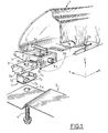
- Figure 1 shows schematically the mounting of a plastic wing 1 on a support metal 2 using a fixing device 3 and a screw 4.
- the fastening device 3 consists of a profiled element 5 whose shape outer conforms to the inner shape of the wing 1 and of a shoe 6 mounted in translation on the underside of the profiled element 5, in the direction of the X axis corresponding to the length of the vehicle.
- Pad 6 protrudes by the underside of the profiled element 5 by a tongue 6a intended to fit into a first groove made on the horizontal part of the wing in contact with the metal support 2.
- the profiled element 5 laterally has a stud 5a intended to be clipped to the bottom of a second converging groove 1b made on the side wall corresponding to wing 1.
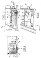
- FIGS. 2 and 3 A particular variant embodiment of the fixing device 3 is detailed in FIGS. 2 and 3: the profiled element 5 is mounted in translation on the shoe 6 by means of a dovetail 6c. Pad 6 is drilled by a vertical hole 6b emerging. Profile element 5 is recalled in translation on the shoe 6 against a stop 5b belonging to said element section 5, in the direction of the negative X, by elastic means. According to the particular variant shown in the figures, these means consist of an elastic blade 5c. We have shown an elastic blade 5c reported to facilitate understanding but it is clear that said blade 5c could be made in one piece with the profiled element 5, for example by molding.
- a staple 7 in the form of "U" consisting of a core 7a connecting a small wing 7b and a large wing 7c, the core 7a being pierced with a hole 7d, is mounted in the shoe 6.
- the two wings 7b, 7c are driven into vertical grooves of said shoe 6 so as to bring the core 7a against the tongue 6a and to make coincide holes 6b and 7d.
- the large wing 7c protrudes above the body of the skate 6 so as to hook the blade 5c and thus maintain the profiled element 5 on pad 6.
- any other elastic means would be suitable also, for example a spring connecting the shoe 6 to the element profile 5.
- the fixing device 3 thus formed is mounted on the wing 1 fitted in the first groove 1a of the wing 1 by the tongue 6a of the shoe 6 until the pin 5a clips into the bottom of the second groove 1b of the wing 1, thus joining the fastening device 3 and wing 1.
- the assembly thus formed can be manipulated and brought to the metal support 2 without special precautions.
- the actual screwing takes place between the threads of the screw 4 and the sheet metal constituting the edges of the hole 7d of the clip 7, the hole 6b being used only for the passage of the screw 4.
- FIG. 5 The assembly performed after adjusting the clearances is shown in Figures 4 and 5. It can be seen in FIG. 5 that the side walls of the element profile 5 are in close contact with the inner side walls of wing 1. During a significant rise in temperature, corresponding for example when painting the paint, there is a dilation of wing 1, dilation which tends to spread the inner side walls of the wing 1 of the side walls of the profiled element 5 thus allowing free longitudinal expansion in the direction of positive X's; indeed, wing 1 is blocked in translation in the direction of negative X because fixed positively at the vehicle door (not shown on the figures). The wing 1 in the expanded position is shown in FIG. 6.
- the second converging groove 1b will return gradually towards the position it occupied after mounting, which is shown in Figure 5. But, as soon as the groove 1b comes into contact with the nipple 5a, it drives the latter in its movement of translation in the direction of the negative X, because the pin 5a is integral with the profiled element 5 itself movable in translation in the X direction negative with respect to the shoe 6 fixed on the metal support 2. Indeed, the translation of the profiled element 5 in the direction of the negative X axis is not prevented by a positive stop as is the case in the other direction with the stop 5b, but simply braked by the restoring force of the leaf spring 5c secured to the profiled element 5 and bearing against the large wing 7c of the clip 7 which is embedded in the shoe 6.
- the plastic of wing 1 undergoes, after return to room temperature, an additional shrinkage which causes a reduction in the dimensions of wing 1 compared to the dimensions before heating.
- the additional withdrawal will result in additional displacement of wing 1 and as a result of the second groove 1b in the direction of the negative X, thus completing the clipping of said stud 5a into said groove 1b to reach the position represented in FIG. 8.
- the additional mobility provided to wing 1, relative to the metal support 2, by the stroke of the shoe 6 therefore allows to compensate for the additional shrinkage of the plastic, after cooling.
- the role of the elastic means, and in particular of the blade 5c, is to ensure that the shoe 6 is well in abutment 5b at the bottom of the groove at the time of mounting the fixing device 3 on the metal support 2 during fitting the wing 1.
Description
L'invention concerne un dispositif de retenue d'un élément plastique de
carrosserie, notamment une aile plastique de véhicule automobile sur un
support métallique.
L'invention concerne plus particulièrement un dispositif de retenue selon le préambule de la revendication 1 d'un
élément plastique de carrosserie sur un support métallique dont le
coefficient de dilatation est inférieur à celui dudit élément plastique, tel qu'il est décrit
dans l'état de la technique le plus proche représenté dans US-A-4 707 020.The invention relates to a device for retaining a plastic element of
bodywork, in particular a plastic wing of a motor vehicle on a
metal support.
The invention relates more particularly to a retaining device according to the preamble of
Certains modèles de véhicules automobiles sont équipés d'ailes en matière plastique. Les coefficients de dilatation étant différents entre la matière plastique constituant les ailes et l'acier constituant la structure, on constaté, lors de l'application d'un traitement de surface nécessitant une augmentation de température, par exemple lors de la cuisson d'une peinture, un déplacement important de l'aile par rapport à la structure puis son retour, lors du refroidissement, en position initiale. Les dispositifs de retenue utilisés avec des ailes en acier ne sont donc pas utilisables tels quels pour la fixation des ailes en matière plastique, car ils imposeraient au plastique des contraintes rédhibitoires.Certain models of motor vehicles are equipped with plastic. The coefficients of expansion being different between the material plastic constituting the wings and the steel constituting the structure, we observed, during the application of a surface treatment requiring a temperature increase, for example when cooking a painting, a significant displacement of the wing compared to the structure then its return, upon cooling, to the initial position. The devices retainers used with steel wings are therefore not usable as which for fixing the plastic wings, because they would impose to plastic unacceptable constraints.
La publication FR-A-2720794 décrit un dispositif de retenue d'un élément plastique de carrosserie sur un support métallique dans lequel une agrafe de fixation dudit élément plastique sur le support dont le coefficient de dilatation est inférieur à celui de l'élément plastique, est constituée notamment par une base de fixation, la base de fixation portant perpendiculairement des languettes d'appui sur l'élément plastique, lesdites languettes étant solidaires d'une entretoise munie d'un trou de passage d'une vis de fixation. Un tel dispositif permet, après la fixation de l'aile sur la caisse, lors du montage, la libre dilatation de ladite aile lors d'un traitement de surface nécessitant une augmentation de température. En effet, à froid, les bords latéraux intérieurs de l'aile épousent les bords latéraux de l'agrafe assurant ainsi, non seulement un blocage de l'aile dans la direction latérale mais aussi dans la direction longitudinale du véhicule. Lors de l'échauffement, l'aile subit une dilatation selon toutes ses dimensions donc en particulier selon sa dimension latérale. Ainsi, dès le début de la dilatation, les bords latéraux intérieurs de l'aile s'écartent des bords latéraux de l'agrafe autorisant ensuite la dilatation longitudinale de l'aile, dilatation longitudinale qui est bien plus importante que la dilatation latérale du fait de la forme même de l'aile. Après refroidissement, l'aile reprend la position à laquelle elle a été fixée lors du montage. Néanmoins, les variations de température provoquent un retrait supplémentaire du plastique en deçà des dimensions initiales de l'aile, retrait qui n'intervient qu'après refroidissement, alors que l'aile est à nouveau bloquée longitudinalement sur l'agrafe. Ce retrait provoque, dans le cas d'une aile avant, un écartement de l'extrémité arrière de ladite aile par rapport à l'extrémité avant de la porte avant, entraínant une augmentation disgracieuse du jeu d'aspect existant entre l'aile et la porte.The publication FR-A-2720794 describes a device for retaining an element body plastic on a metal support in which a staple for fixing said plastic element to the support, the coefficient of expansion is less than that of the plastic element, consists in particular by a fixing base, the fixing base carrying perpendicularly support tabs on the plastic element, said tabs being integral with a spacer provided with a through hole a fixing screw. Such a device allows, after the attachment of the wing on the body, during assembly, the free expansion of said wing during a surface treatment requiring an increase in temperature. In effect, when cold, the inner lateral edges of the wing follow the edges side of the clip thus ensuring, not only a blocking of the wing in lateral direction but also in the longitudinal direction of the vehicle. During the heating, the wing undergoes a dilation according to all its dimensions therefore in particular according to its lateral dimension. So, from the beginning of expansion, the inner side edges of the wing move away from lateral edges of the clip then allowing the longitudinal expansion of the wing, longitudinal expansion which is much more important than the expansion lateral due to the very shape of the wing. After cooling, the wing takes up the position to which it was fixed during assembly. However, temperature variations cause further shrinkage of the plastic below the initial dimensions of the wing, withdrawal which does not occur only after cooling, while the wing is blocked again longitudinally on the clip. This withdrawal causes, in the case of a wing front, a spacing of the rear end of said wing relative to the front end of the front door, causing an increase unsightly of the play of aspect existing between the wing and the door.
Le dispositif selon l'invention vise à palier cet inconvénient. A cet effet, l'invention concerne un dispositif de retenue d'un élément plastique de carrosserie sur un support métallique dont le coefficient de dilatation est inférieur à celui dudit élément plastique, le dispositif étant du type comportant un élément profilé monté à l'intérieur de l'élément plastique. Le dispositif est caractérisé en ce que l'élément profilé est solidarisé au support métallique par l'intermédiaire de moyens de liaison permettant un déplacement dudit élément profilé par rapport audit support métallique.The device according to the invention aims to overcome this drawback. To this end, the invention relates to a device for retaining a plastic element of bodywork on a metal support whose coefficient of expansion is lower than that of said plastic element, the device being of the type comprising a profiled element mounted inside the plastic element. The device is characterized in that the profiled element is secured to the metal support by means of connecting means allowing a displacement of said profiled element relative to said metal support.
Selon une autre caractéristique de l'invention, les moyens de liaison sont constitués par un patin fixé sur le support métallique, l'élément profilé étant monté à translation sur ledit patin et rappelé en butée par des moyens élastiques.According to another characteristic of the invention, the connecting means are formed by a shoe fixed on the metal support, the profiled element being mounted in translation on said shoe and returned to abutment by means elastic.
Cette caractéristique procure à l'élément plastique une liberté en translation par rapport au support métallique, et ce, après le refroidissement dudit élément plastique, ce qui permet de prendre en compte le retrait supplémentaire du plastique intervenant après refroidissement.This characteristic gives the plastic element freedom in translation relative to the metal support, and this after cooling of said plastic element, which allows taking into counts the additional plastic removal after cooling.
Selon une autre caractéristique de l'invention, le patin dépasse de la face inférieure de l'élément profilé par une languette destinée à rentrer dans une première rainure pratiquée sur la partie de l'élément plastique assurant la fixation sur le support métallique. According to another characteristic of the invention, the shoe protrudes from the face bottom of the element profiled by a tab intended to enter into a first groove made on the part of the plastic element ensuring fixing on the metal support.
Cette caractéristique permet la libre dilatation du plastique qui, ainsi, n'est pas directement en contact avec le support métallique.This characteristic allows the free expansion of the plastic which, thus, is not not directly in contact with the metal support.
Selon une autre caractéristique de l'invention, l'élément profilé comporte un tenon destiné à venir se clipser au fond d'une seconde rainure convergente pratiquée sur la paroi correspondante de l'élément plastique.According to another characteristic of the invention, the profiled element comprises a post intended to be clipped to the bottom of a second groove converging formed on the corresponding wall of the plastic element.
Cette caractéristique permet de solidariser le dispositif de fixation sur l'élément plastique à fixer, préalablement à son montage sur l'élément métallique ce qui facilite les manipulations.This characteristic makes it possible to secure the fixing device to the plastic element to be fixed, prior to mounting on the element metallic which facilitates handling.
Selon une autre caractéristique de l'invention, les moyens élastiques sont constitués par une lame élastique réalisée d'une seule pièce avec l'élément profilé, ladite lame élastique coopérant avec une protubérance située à la surface du patin.According to another characteristic of the invention, the elastic means are constituted by an elastic blade made in one piece with the element profiled, said elastic blade cooperating with a protuberance located at the skate surface.
La lame élastique peut ainsi être obtenue par moulage en une seule pièce avec la partie profilée, ce qui est particulièrement simple et économique.The elastic blade can thus be obtained by molding in one piece with the profiled part, which is particularly simple and economical.
Selon une autre caractéristique de l'invention, l'élément profilé est monté à translation sur le patin par l'intermédiaire d'une queue d'aronde.According to another characteristic of the invention, the profiled element is mounted translation on the skate via a dovetail.
Selon une autre caractéristique de l'invention, le patin est fixé sur le support métallique au moyen d'une vis traversant un trou dudit support métallique pour se visser dans un trou fileté pratiqué dans ledit patin.According to another characteristic of the invention, the shoe is fixed on the metal support by means of a screw passing through a hole in said support metallic to be screwed into a threaded hole made in said shoe.
D'autres caractéristiques et avantages apparaítront à la lecture de la description d'un exemple de dispositif selon l'invention, en référence aux dessins dans lesquels :
- la figure 1 est une vue en perspective éclatée du montage de l'aile sur le support au moyen du dispositif de fixation selon l'invention,
- la figure 2 est une vue en coupe verticale du dispositif de fixation selon l'invention,
- la figure 3 est une vue en coupe horizontale du dispositif de fixation selon l'invention,
- la figure 4 est une vue en coupe verticale de l'aile montée avant dilatation,
- la figure 5 est une vue en coupe horizontale de l'aile avant dilatation,
- la figure 6 est une vue en coupe horizontale de l'aile en cours de dilatation,
- la figure 7 est une vue en coupe horizontale de l'aile après son refroidissement,
- la figure 8 est une vue en coupe horizontale de l'aile après le retrait supplémentaire.
- FIG. 1 is an exploded perspective view of the mounting of the wing on the support by means of the fixing device according to the invention,
- FIG. 2 is a view in vertical section of the fixing device according to the invention,
- FIG. 3 is a view in horizontal section of the fixing device according to the invention,
- FIG. 4 is a view in vertical section of the wing mounted before expansion,
- FIG. 5 is a view in horizontal section of the wing before expansion,
- FIG. 6 is a view in horizontal section of the wing during expansion,
- FIG. 7 is a view in horizontal section of the wing after it has cooled,
- Figure 8 is a horizontal sectional view of the wing after further removal.
La figure 1 schématise le montage d'une aile plastique 1 sur un support
métallique 2 à l'aide d'un dispositif de fixation 3 et d'une vis 4. Le
dispositif de fixation 3 est constitué d'un élément profilé 5 dont la forme
extérieure épouse la forme intérieure de l'aile 1 et d'un patin 6 monté en
translation sur la face inférieure de l'élément profilé 5, dans la direction de
l'axe des X correspondant à la longueur du véhicule. Le patin 6 dépasse de
la face inférieure de l'élément profilé 5 par une languette 6a destinée à
rentrer dans une première rainure la pratiquée sur la partie horizontale de
l'aile en contact avec le support métallique 2. L'élément profilé 5
comporte latéralement un tenon 5a destiné à venir se clipser au fond d'une
seconde rainure 1b convergente pratiquée sur la paroi latérale
correspondante de l'aile 1.Figure 1 shows schematically the mounting of a
Une variante particulière de réalisation du dispositif de fixation 3 est
détaillée sur les figures 2 et 3 : l'élément profilé 5 est monté à translation
sur le patin 6 par l'intermédiaire d'une queue d'aronde 6c. Le patin 6 est
percé par un trou vertical 6b débouchant. L'élément profilé 5 est rappelé
en translation sur le patin 6 contre une butée 5b appartenant audit élément
profilé 5, dans la direction des X négatifs, par des moyens élastiques.
Selon la variante particulière représentée sur les figures, ces moyens
consistent en une lame élastique 5c. On a représenté une lame élastique 5c
rapportée pour faciliter la compréhension mais il est clair que ladite
lame 5c pourrait être réalisée d'une seule pièce avec l'élément profilé 5,
par exemple par moulage. Dans cette variante, une agrafe 7 en forme de
« U » constituée d'une âme 7a reliant une petite aile 7b et une grande
aile 7c, l'âme 7a étant percée d'un trou 7d, est montée dans le patin 6. Les
deux ailes 7b,7c sont enfoncées dans des rainures verticales dudit patin 6
de manière à amener l'âme 7a contre la languette 6a et à faire coïncider
les trous 6b et 7d. La grande aile 7c dépasse au dessus du corps du patin 6
de manière à accrocher la lame 5c et maintenir ainsi l'élément profilé 5 sur
le patin 6. Il est bien clair que tout autre moyen élastique conviendrait
également, comme par exemple un ressort reliant le patin 6 à l'élément
profilé 5.A particular variant embodiment of the
Le dispositif de fixation 3 ainsi constitué est monté sur l'aile 1 emboíté
dans la première rainure 1a de l'aile 1 par la languette 6a du patin 6
jusqu'à ce que le téton 5a vienne se clipser au fond de la seconde
rainure 1b de l'aile 1, solidarisant ainsi le dispositif de fixation 3 et
l'aile 1. L'ensemble ainsi constitué peut être manipulé et amené sur le
support métallique 2 sans précaution particulière. On réalise alors la
fixation de l'aile 1 sur le support métallique 2 à l'aide d'une vis 4 vissée à
travers un trou 2a du support métallique 2 dans le trou 6b du patin 6. Dans
l'exemple représenté sur les figures, le vissage proprement dit a lieu entre
les filets de la vis 4 et la tôle constituant les bords du trou 7d de
l'agrafe 7, le trou 6b ne servant qu'au passage de la vis 4. Mais il est clair
que l'on peut également envisager une variante simplifiée dépourvue
d'agrafe 7 dans laquelle le vissage est réalisé directement dans le trou 6b.
L'ajustement des jeux entre l'aile 1, le capot et la porte (non représentés)
est réalisé grâce à un diamètre du trou 2a supérieur à celui de la vis 4.
Les épaisseurs des languettes 6a du patin 6 et de l'âme 7a sont choisies de
manière à ce que leur somme soit supérieure à l'épaisseur locale de l'aile 1
permettant à celle-ci de ne pas reposer sur la carrosserie 2 au niveau du
trou 2a.The
L'assemblage réalisé après réglage des jeux est représenté sur les figures 4
et 5. On peut voir sur la figure 5 que les parois latérales de l'élément
profilé 5 sont en contact étroit avec les parois latérales intérieures de
l'aile 1. Lors d'une élévation importante de température, correspondant
par exemple à la cuisson de la peinture, il se produit une dilatation de
l'aile 1, dilatation qui tend à écarter les parois latérales intérieures de
l'aile 1 des parois latérales de l'élément profilé 5 permettant ainsi une libre
dilatation longitudinale dans la direction des X positifs ; en effet, l'aile 1
est bloquée en translation dans la direction des X négatifs car fixée
positivement au niveau de la porte du véhicule (non représentée sur les
figures). L'aile 1 en position dilatée est représentée sur la figure 6. Cette
libre dilatation est facilitée par le fait que l'aile 1 ne repose pas
directement sur le support métallique 2 au niveau du trou 2a comme on l'a
vu ci-dessus. Cette dilatation entraíne par ailleurs la sortie du téton Sa hors
du clip constitué par la seconde rainure 1b convergente disposée sur la
paroi latérale correspondante de l'aile 1. En effet, la seconde rainure 1b
est entraínée dans la direction des X positifs par le mouvement de l'aile 1
par rapport au support métallique 2, mouvement résultant de la dilatation.
Au contraire, le téton 5a est immobilisé par rapport au support
métallique 2 car solidaire de l'élément profilé 5 lui-même bloqué en
translation dans la direction des X positifs par sa butée 5b en appui contre
le patin 6 lui-même fixé au support 2 par l'intermédiaire de l'agrafe 7 et
de la vis 4.The assembly performed after adjusting the clearances is shown in Figures 4
and 5. It can be seen in FIG. 5 that the side walls of the
Lors du refroidissement, la seconde rainure 1b convergente va revenir
petit à petit vers la position qu'elle occupait après le montage, qui est
représentée sur la figure 5. Mais, dès que la rainure 1b entre en contact
avec le téton 5a, elle entraíne ce dernier dans son mouvement de
translation dans la direction des X négatifs, car le téton 5a est solidaire de
l'élément profilé 5 lui-même mobile en translation dans la direction des X
négatifs par rapport au patin 6 fixé sur le support métallique 2. En effet, la
translation de l'élément profilé 5 dans la direction de l'axe des X négatifs
n'est pas empêchée par une butée positive comme c'est le cas dans l'autre
sens avec la butée 5b, mais simplement freinée par la force de rappel de la
lame ressort 5c solidaire de l'élément profilé 5 et en appui contre la
grande aile 7c de l'agrafe 7 qui est encastrée dans le patin 6. Or, comme
la force de rappel de la lame élastique 5c est inférieure à la force
nécessaire au clipsage du téton 5a dans la seconde rainure 1b, on assiste
d'abord à la translation de l'élément profilé 5 par rapport au patin 6. Cette
translation s'arrêtera lorsque la lame 5c viendra en contact avec une butée
issue par exemple de moulage sur l'élément profilé 5. Il s'ensuit qu'en fin
de refroidissement, et bien que l'aile 1 ait retrouvée sa position initiale
correspondant à la figure 5, l'élément profilé 5 est, lui, décalé dans la
direction des X négatifs d'une valeur égale à la course autorisée du patin
6 par rapport à l'élément profilé 5. Cette position est représentée sur la
figure 7 où il apparaít que le téton 5a n'est pas tout à fait clipsé dans la
seconde rainure 1b.During cooling, the second converging
Or, comme on a déjà vu plus haut, le plastique de l'aile 1 subit, après
retour à la température ambiante, un retrait supplémentaire qui provoque
une diminution des dimensions de l'aile 1 par rapport aux dimensions
avant chauffage. Comme l'aile 1 est fixée au niveau de la porte du
véhicule (non représentée sur les figures) située dans la direction des X
négatifs, à l'opposé du dispositif de fixation 3, le retrait supplémentaire va
se traduire par un déplacement supplémentaire de l'aile 1 et par suite de la
seconde rainure 1b dans la direction des X négatifs, complétant ainsi le
clipsage dudit téton 5a dans ladite rainure 1b pour atteindre la position
représentée sur la figure 8. La mobilité supplémentaire procurée à l'aile 1,
par rapport au support métallique 2, par la course du patin 6 permet donc
de compenser le retrait supplémentaire du plastique, après refroidissement.
Le rôle des moyens élastiques, et en particulier de la lame 5c est d'assurer
que le patin 6 soit bien en butée 5b en fond de rainure au moment du
montage du dispositif de fixation 3 sur le support métallique 2 lors du
montage de l'aile 1.However, as we have already seen above, the plastic of
Claims (6)
- A device for retaining a plastic bodywork member (I) on a metal support (2) whose coefficient of expansion is lower than that of the plastic member (1), of the type comprising a profiled member (5) mounted within the plastic member (1) and connected to the metal support (2) by means of connection means (6) enabling a displacement of the profiled member (5) with respect to the metal support (2), these connection means being formed by a shoe (6) secured to the metal support (2), the profiled member (5) being mounted in translation on the shoe (6), characterised in that the profiled member (5) is recalled against an abutment (5b) belonging to the profiled member (5) by elastic means (5c), the abutment (5b) locking any translation of the profiled member (5) in the direction of expansion of the plastic member (1).
- A retaining device as claimed in the preceding claim, characterised in that the shoe (6) projects beyond the lower surface of the profiled member (5) by means of a tongue (6a) adapted to be fitted in a first groove (1a) provided on the portion of the plastic member (1) ensuring fastening on the metal support (2).
- A retaining device as claimed in any one of claims 1 and 2, characterised in that the profiled member (5) comprises a tenon (5a) adapted to be clipped into the base of a second convergent groove (1b) provided on the corresponding wall of the plastic member (1).
- A retaining device as claimed in any one of claims 1 to 3, characterised in that the elastic means are formed by an elastic blade (5c) made in one piece with the profiled member (5), which elastic blade (5c) cooperates with a projection disposed on the surface of the shoe (6).
- A retaining device as claimed in any one of claims 1 to 4, characterised in that the profiled member (5) is mounted in translation on the shoe (6) by means of a dovetail (6c).
- A retaining device as claimed in any one of claims 1 to 5, characterised in that the shoe (6) is fixed to the metal support (2) by means of a screw (4) passing through a hole (2a) of the metal support (2) in order to be screwed into a threaded hole (6b) provided in this shoe (6).
Applications Claiming Priority (2)
| Application Number | Priority Date | Filing Date | Title |
|---|---|---|---|
| FR9604318 | 1996-04-05 | ||
| FR9604318A FR2747092B1 (en) | 1996-04-05 | 1996-04-05 | IMPROVEMENT TO A DEVICE FOR RETAINING A PLASTIC WING ON A METAL CASE |
Publications (2)
| Publication Number | Publication Date |
|---|---|
| EP0799759A1 EP0799759A1 (en) | 1997-10-08 |
| EP0799759B1 true EP0799759B1 (en) | 2001-05-16 |
Family
ID=9490969
Family Applications (1)
| Application Number | Title | Priority Date | Filing Date |
|---|---|---|---|
| EP19970400714 Expired - Lifetime EP0799759B1 (en) | 1996-04-05 | 1997-03-28 | Device for carrying a plastic mud guard on a metallic body |
Country Status (4)
| Country | Link |
|---|---|
| EP (1) | EP0799759B1 (en) |
| DE (1) | DE69704806T2 (en) |
| ES (1) | ES2157052T3 (en) |
| FR (1) | FR2747092B1 (en) |
Cited By (2)
| Publication number | Priority date | Publication date | Assignee | Title |
|---|---|---|---|---|
| EP1319581A2 (en) | 2001-12-11 | 2003-06-18 | Volkswagen Aktiengesellschaft | Plastic mud-guard for motor vehicles |
| US8805957B2 (en) | 1998-05-29 | 2014-08-12 | Access Co., Ltd. | Method and apparatus for communications over low bandwidth communications networks |
Families Citing this family (7)
| Publication number | Priority date | Publication date | Assignee | Title |
|---|---|---|---|---|
| DE10060782A1 (en) * | 2000-12-07 | 2002-06-13 | Bayerische Motoren Werke Ag | Device for fastening two components |
| US7261489B2 (en) * | 2004-05-20 | 2007-08-28 | United Technologies Corporation | Fastener assembly for attaching a non-metal component to a metal component |
| DE102004052637A1 (en) * | 2004-10-29 | 2006-05-04 | Rehau Ag + Co | Arrangement for fastening a component |
| DE102006029294A1 (en) * | 2006-06-23 | 2007-12-27 | Rehau Ag + Co. | Fastening system for motor vehicle, has displacement limiting unit connected with one of mud guard or fastening unit after connecting mud guard and carriage body with each other to intervene in guide way |
| DE202008010321U1 (en) * | 2008-08-02 | 2009-12-17 | Rehau Ag + Co | Plastic fender and motor vehicle |
| EP2722258A1 (en) * | 2012-10-17 | 2014-04-23 | Compagnie Plastic Omnium | Motor-vehicle component capable of withstanding thermal deformation |
| DE202016001857U1 (en) * | 2016-03-21 | 2017-06-22 | Liebherr-Mischtechnik Gmbh | Truck mixer |
Family Cites Families (5)
| Publication number | Priority date | Publication date | Assignee | Title |
|---|---|---|---|---|
| US4707020A (en) * | 1985-07-16 | 1987-11-17 | Honda Giken Kogyo Kabushiki Kaisha | Body structure of a motor vehicle having exterior panels made of synthetic resins |
| FR2632691B1 (en) * | 1988-06-10 | 1990-08-31 | Renault | PLASTIC PIECE FASTENING CLIP |
| US5098765A (en) * | 1989-12-22 | 1992-03-24 | Chrysler Corportion | Fastening arrangement for plastic vehicle panel |
| US5429412A (en) * | 1993-08-26 | 1995-07-04 | Chrysler Corporation | Plastic fender retainer arrangement |
| FR2720794B1 (en) * | 1994-06-01 | 1996-07-12 | Renault | Device for retaining a plastic bodywork element on a metal support and method for mounting the device. |
-
1996
- 1996-04-05 FR FR9604318A patent/FR2747092B1/en not_active Expired - Lifetime
-
1997
- 1997-03-28 DE DE1997604806 patent/DE69704806T2/en not_active Expired - Fee Related
- 1997-03-28 ES ES97400714T patent/ES2157052T3/en not_active Expired - Lifetime
- 1997-03-28 EP EP19970400714 patent/EP0799759B1/en not_active Expired - Lifetime
Cited By (2)
| Publication number | Priority date | Publication date | Assignee | Title |
|---|---|---|---|---|
| US8805957B2 (en) | 1998-05-29 | 2014-08-12 | Access Co., Ltd. | Method and apparatus for communications over low bandwidth communications networks |
| EP1319581A2 (en) | 2001-12-11 | 2003-06-18 | Volkswagen Aktiengesellschaft | Plastic mud-guard for motor vehicles |
Also Published As
| Publication number | Publication date |
|---|---|
| DE69704806T2 (en) | 2001-11-22 |
| DE69704806D1 (en) | 2001-06-21 |
| ES2157052T3 (en) | 2001-08-01 |
| FR2747092A1 (en) | 1997-10-10 |
| EP0799759A1 (en) | 1997-10-08 |
| FR2747092B1 (en) | 1998-05-07 |
Similar Documents
| Publication | Publication Date | Title |
|---|---|---|
| EP0799758B1 (en) | Device for sliding attachment of a plastic mud guard | |
| EP0799759B1 (en) | Device for carrying a plastic mud guard on a metallic body | |
| FR2779467A1 (en) | Cavity wall spacer for placing insulation covering at a set distance from a wall | |
| FR2759744A1 (en) | PLASTIC PART WITH INTEGRATED SLIDING ATTACHMENT | |
| EP1326024B1 (en) | Fastening for joining a piece to a support and to position it in relation to its environment, especially an automobile body part | |
| EP1957733A1 (en) | Locking device | |
| EP2203618B1 (en) | Device acting as a stand-off between an opening element and a fixed element, particularly of a motor vehicle | |
| EP2062804A1 (en) | Device and method for attaching a wing assembly to an automobile body shell wall | |
| FR2768197A1 (en) | Fixing plate for joining vehicle bodywork | |
| FR2911106A1 (en) | Support for fixing body element i.e. front wing, of motor vehicle, has connection surface supported against complementary surface of body element to form sliding connection between support and body element | |
| WO1999029559A1 (en) | Device for fixing a vehicle lateral fender on a support element | |
| FR2585756A1 (en) | Junction device between a housing and an espagnolette extension with endpiece and with rods | |
| FR2720794A1 (en) | Retaining bracket for fixing plastics bodywork onto metal body | |
| FR2900991A1 (en) | Brake liquid reservoir assembly for motor vehicle, has fixation orifice cooperating with fixation unit e.g. screw, and gripping unit, fixed to tab, sliding inside housing, placed in support, to form slide connection with support | |
| EP3849876B1 (en) | Assembly forming a trim casing for a steering column and vehicle having such a casing | |
| FR2711196A1 (en) | Caged nut for fitting on a rail or the like and assembly obtained using this nut | |
| FR2861439A1 (en) | Rear light fixing device for motor vehicle, has fastener mounted in housing of light support, and displaced following clearance along direction perpendicular to plane formed by longitudinal axis of vane and direction of vane displacement | |
| FR2902845A1 (en) | Connection piece for roller shutter assembling device, has base with sides elastically deformed for varying length and width of base, and clip projected on surfaces of base and cooperated with indent of head of connection tab | |
| EP0845569A1 (en) | Running wheel assembly for sliding door | |
| FR2705746A1 (en) | Device for fastening an element, such as an armrest or interior door handle of a motor vehicle, to a fixed structure | |
| EP2059404A1 (en) | Device for fixing a seal to a vehicle structure | |
| FR2992378A1 (en) | Fixing part for fixing anti-air recirculation device in vehicle i.e. car, has fastening unit comprising resilient unit that is placed in support against support element to exert force in direction of head of leg of click-and-ratchet work | |
| FR2957955A1 (en) | Door sill for dwelling, has retaining rod inserted into hole so as to be committed in retaining opening, bar formed with cavity opened in lower face to place projecting parts, and sill bar covering sill on ground | |
| FR2768196A1 (en) | Fixing plate for vehicle bodywork sections | |
| EP1452398A1 (en) | Profile for a motor vehicle door and its production process |
Legal Events
| Date | Code | Title | Description |
|---|---|---|---|
| PUAI | Public reference made under article 153(3) epc to a published international application that has entered the european phase |
Free format text: ORIGINAL CODE: 0009012 |
|
| AK | Designated contracting states |
Kind code of ref document: A1 Designated state(s): BE DE ES GB IT |
|
| 17P | Request for examination filed |
Effective date: 19980310 |
|
| 17Q | First examination report despatched |
Effective date: 19990625 |
|
| GRAG | Despatch of communication of intention to grant |
Free format text: ORIGINAL CODE: EPIDOS AGRA |
|
| GRAG | Despatch of communication of intention to grant |
Free format text: ORIGINAL CODE: EPIDOS AGRA |
|
| GRAG | Despatch of communication of intention to grant |
Free format text: ORIGINAL CODE: EPIDOS AGRA |
|
| GRAH | Despatch of communication of intention to grant a patent |
Free format text: ORIGINAL CODE: EPIDOS IGRA |
|
| GRAH | Despatch of communication of intention to grant a patent |
Free format text: ORIGINAL CODE: EPIDOS IGRA |
|
| GRAA | (expected) grant |
Free format text: ORIGINAL CODE: 0009210 |
|
| AK | Designated contracting states |
Kind code of ref document: B1 Designated state(s): BE DE ES GB IT |
|
| GBT | Gb: translation of ep patent filed (gb section 77(6)(a)/1977) |
Effective date: 20010521 |
|
| REF | Corresponds to: |
Ref document number: 69704806 Country of ref document: DE Date of ref document: 20010621 |
|
| REG | Reference to a national code |
Ref country code: ES Ref legal event code: FG2A Ref document number: 2157052 Country of ref document: ES Kind code of ref document: T3 |
|
| ITF | It: translation for a ep patent filed |
Owner name: JACOBACCI & PERANI S.P.A. |
|
| REG | Reference to a national code |
Ref country code: GB Ref legal event code: IF02 |
|
| PLBE | No opposition filed within time limit |
Free format text: ORIGINAL CODE: 0009261 |
|
| STAA | Information on the status of an ep patent application or granted ep patent |
Free format text: STATUS: NO OPPOSITION FILED WITHIN TIME LIMIT |
|
| 26N | No opposition filed | ||
| PGFP | Annual fee paid to national office [announced via postgrant information from national office to epo] |
Ref country code: IT Payment date: 20060331 Year of fee payment: 10 |
|
| PGFP | Annual fee paid to national office [announced via postgrant information from national office to epo] |
Ref country code: DE Payment date: 20070316 Year of fee payment: 11 |
|
| PGFP | Annual fee paid to national office [announced via postgrant information from national office to epo] |
Ref country code: ES Payment date: 20070329 Year of fee payment: 11 |
|
| GBPC | Gb: european patent ceased through non-payment of renewal fee |
Effective date: 20070328 |
|
| PGFP | Annual fee paid to national office [announced via postgrant information from national office to epo] |
Ref country code: BE Payment date: 20070419 Year of fee payment: 11 |
|
| PG25 | Lapsed in a contracting state [announced via postgrant information from national office to epo] |
Ref country code: GB Free format text: LAPSE BECAUSE OF NON-PAYMENT OF DUE FEES Effective date: 20070328 |
|
| BERE | Be: lapsed |
Owner name: *RENAULT Effective date: 20080331 |
|
| PGFP | Annual fee paid to national office [announced via postgrant information from national office to epo] |
Ref country code: GB Payment date: 20060322 Year of fee payment: 10 |
|
| PG25 | Lapsed in a contracting state [announced via postgrant information from national office to epo] |
Ref country code: DE Free format text: LAPSE BECAUSE OF NON-PAYMENT OF DUE FEES Effective date: 20081001 |
|
| PG25 | Lapsed in a contracting state [announced via postgrant information from national office to epo] |
Ref country code: BE Free format text: LAPSE BECAUSE OF NON-PAYMENT OF DUE FEES Effective date: 20080331 |
|
| REG | Reference to a national code |
Ref country code: ES Ref legal event code: FD2A Effective date: 20080329 |
|
| PG25 | Lapsed in a contracting state [announced via postgrant information from national office to epo] |
Ref country code: ES Free format text: LAPSE BECAUSE OF NON-PAYMENT OF DUE FEES Effective date: 20080329 |
|
| PG25 | Lapsed in a contracting state [announced via postgrant information from national office to epo] |
Ref country code: IT Free format text: LAPSE BECAUSE OF NON-PAYMENT OF DUE FEES Effective date: 20070328 |