EP0798901A1 - Simultaneous transmission of power clock and data - Google Patents
Simultaneous transmission of power clock and data Download PDFInfo
- Publication number
- EP0798901A1 EP0798901A1 EP97400633A EP97400633A EP0798901A1 EP 0798901 A1 EP0798901 A1 EP 0798901A1 EP 97400633 A EP97400633 A EP 97400633A EP 97400633 A EP97400633 A EP 97400633A EP 0798901 A1 EP0798901 A1 EP 0798901A1
- Authority
- EP
- European Patent Office
- Prior art keywords
- voltage
- conductor
- circuit
- signal
- slave
- Prior art date
- Legal status (The legal status is an assumption and is not a legal conclusion. Google has not performed a legal analysis and makes no representation as to the accuracy of the status listed.)
- Granted
Links
Images


Classifications
-
- H—ELECTRICITY
- H04—ELECTRIC COMMUNICATION TECHNIQUE
- H04B—TRANSMISSION
- H04B3/00—Line transmission systems
- H04B3/54—Systems for transmission via power distribution lines
- H04B3/548—Systems for transmission via power distribution lines the power on the line being DC
-
- H—ELECTRICITY
- H04—ELECTRIC COMMUNICATION TECHNIQUE
- H04L—TRANSMISSION OF DIGITAL INFORMATION, e.g. TELEGRAPHIC COMMUNICATION
- H04L25/00—Baseband systems
- H04L25/02—Details ; arrangements for supplying electrical power along data transmission lines
-
- H—ELECTRICITY
- H04—ELECTRIC COMMUNICATION TECHNIQUE
- H04L—TRANSMISSION OF DIGITAL INFORMATION, e.g. TELEGRAPHIC COMMUNICATION
- H04L25/00—Baseband systems
- H04L25/38—Synchronous or start-stop systems, e.g. for Baudot code
- H04L25/40—Transmitting circuits; Receiving circuits
- H04L25/49—Transmitting circuits; Receiving circuits using code conversion at the transmitter; using predistortion; using insertion of idle bits for obtaining a desired frequency spectrum; using three or more amplitude levels ; Baseband coding techniques specific to data transmission systems
- H04L25/4902—Pulse width modulation; Pulse position modulation
-
- H—ELECTRICITY
- H04—ELECTRIC COMMUNICATION TECHNIQUE
- H04L—TRANSMISSION OF DIGITAL INFORMATION, e.g. TELEGRAPHIC COMMUNICATION
- H04L5/00—Arrangements affording multiple use of the transmission path
- H04L5/14—Two-way operation using the same type of signal, i.e. duplex
- H04L5/1423—Two-way operation using the same type of signal, i.e. duplex for simultaneous baseband signals
Definitions
- the invention relates to the transmission of digital data along a communications bus from one electronic circuit to another.
- it relates to serial communications over a bus containing a minimum number of conductors.
- communications between two circuits take place over a communications bus between a "master” circuit and a “slave” circuit.
- the slave sends data along the bus only at the behest of the master. This is particularly the case where one master circuit needs to communicate with a number of interchangeable or removable slave circuits, each of which may store some information.
- Such slave circuits may be tags used to identify articles, which are either brought only momentarily into contact with the communications bus, or which need to provide some information about themselves the first time that they are brought into contact with this bus.
- a communications bus for use between a microprocessor master circuit and a memory device slave circuit comprises at least four conductors: the ground voltage supply, a power supply voltage, a clock signal and a bidirectional data conductor. Where chip select and deselect commands are needed, a dedicated combination of clock and data signals may be used, and interpreted as chip select/deselect by the slave circuit.
- a two-wire communications bus is known, as described by Dallas Semiconductors, with reference to their DS2400 product. This uses one ground conductor and one signal conductor. The signals comprise pulses of 0V to 5V relative to the ground conductor.
- the invention aims to provide a method for bidirectional communication between a master circuit and a slave circuit, providing the necessary power supply, clock signals and control signals, using a minimum number of conductors.
- the invention further aims to provide an identification tag which contains no power supply, but which may be driven by a communications bus which has a minimum number of connectors, yet conveys clocking signals, a power supply, data and control signals.
- the invention further aims to provide a disposable item containing a tag as described, wherein the connection of a communications bus as described allows information about the disposable item to be read from and stored in the tag.
- the invention provides a method and device for encoding and transmitting a clock signal, a supply voltage and bidirectional digital data from a master circuit to a slave circuit, including the steps of: holding a first conductor at a first voltage; periodically raising the first conductor to a second voltage, a fixed period after a previous raising to the second voltage; holding the first conductor at the second voltage for predetermined periods, then returning the first conductor to the first voltage; controlling the predetermined periods to each have a logical significance; characterised in that the method further comprises the steps of: holding a second conductor at a third voltage different from the first and second voltages; measuring the voltage of the first conductor at a temporal offset with respect to the instant of said raising of said first conductor to a second voltage; interpreting the measured voltage according to predetermined logical significances; and raising the first conductor to the second voltage, this raising being used as a clock signal.
- FIG. 1 shows the overall system of the invention.
- the master circuit a microprocessor ⁇ P
- the master circuit is supplied by supply voltages Vcc and GND. Normally, these are set at +5V and 0V respectively.
- a communications bus B connects the master circuit ⁇ P to a slave circuit M.
- the slave circuit M does not have separate supply voltage connections.
- the master circuit contains input and output interfaces, respectively ⁇ PI, ⁇ PO, and a clock generating circuit ⁇ PC.
- the slave circuit contains input and output interfaces MI, MO, a supply voltage generating circuit MV for supplying the slave circuit and a timing circuit MC.
- the two conductors making up the communications bus are a signal conductor S and a ground conductor G. The ground conductor is connected to GND, and the signal conductor S is connected to all of the input and output interfaces and the supply voltage generating circuit MV.
- the voltage of the signal line S may take one of two values - a higher value V1 and a lower value V0. These values may typically be +5V and +3V respectively.
- a stable supply voltage to the slave circuit M may easily be derived from the voltage of the signal conductor S, by supply voltage generating circuit MV. This may be done in one of the following at least three ways, as illustrated in figures 2-4:
- Figure 5A shows an extract of a typical communication along the communication bus of the invention.
- the digital data transmitted by the communications bus of the invention is carried in a sequence of pulses varying between the voltages V0 and V1, visible in figure 2.
- a voltage comparator may be used in the slave circuit M, with a threshold value set between V0 and V1.
- a signal out(t) shown in figure 5B may be produced by such a comparator, which translates a high voltage V1 on the signal conductor S to a high (1) value at approximately the supply level Vcm of the comparator; and a low voltage V0 on the signal conductor S to a low value (0) at approximately the voltage of ground conductor G.
- each rising transition corresponds to a clocking edge, indicated by arrowheads on the rising edges in figure 5B.
- each 0 to 1 transition of the out(t) signal is at a fixed delay T from the previous one.
- Periods P0, P1 in figures 5A, 5B represent the transmission of data bits representing a 0 and a 1, respectively. Each period is of duration T, and lasts from a start time t1 until a time t1+T, and from time t1+T to time t1+2T, respectively.
- period P0 a rising edge is present at instant t1 to indicate the beginning of a clock period.
- Signals out(t), S remain at their respective high values for a duration T0, then return to their respective low values.
- a subsequent period P1 begins at instant t1+T, one clock period T after the rising edge at t1.
- period P1 a rising edge is present at instant t1+T, to indicate the beginning of a clock period.
- the signals S, out(t) remain at their respective high values for a duration T1, then return to their low values.
- Each of these periods P0, P1 transmits one bit of data.
- a subsequent period begins at instant t1+2T, one clock period T after the rising edge at t1+T.
- Td The value of the signal out(t) is sampled at a delay Td after each clocking edge, at instants marked with a dotted line.
- Td is selected to be longer than T0 but shorter than T1, so the value of this sample gives the value of the data bit being transmitted: "0" for period P0 (at instant t1+Td) and "1" for period P1 (at instant t1+T+Td).
- Period Pmx indicates an enabling signal voltage transmitted by the master circuit to allow the slave circuit to return data.
- a rising edge occurs at time t1+3T, and the signals S, out(t) remain at a high value for a delay of Ts, which may be equal to, or preferably longer than time T1.
- the output interface ⁇ PO of the master circuit ⁇ P must present a high impedance for voltages between V0 and V1, but a low impedance for voltages of V0 and less, to ensure that the voltage of the signal conductor S does not fall below V0.
- Period Pm0 of figures 5A, 5B shows the signal on conductor S and signal out(t) provided by the slave circuit when the slave circuit transmits a 0.
- a low impedance circuit in the slave circuit output interface MO pulls the line S to the value V0, a delay of Tm after the clocking edge t1+4T, for a length of time Tm0.
- This length of time Tm0 is chosen to expire after Ts.
- the pulling of the voltage of conductor S to a low value is indicated by a thickened line. This is possible, due to the output impedance of the master circuit, discussed earlier, which makes it easy for the slave to pull the signal conductor to the V0 level, but not below V0.
- the slave When the slave wishes to transmit a 1, the slave simply leaves the enabling signal transmitted by master circuit as it is (as in period Pm1 of figures 5A, 5B).
- the master circuit samples the value of the signal S at a delay Tmx after the clocking edge. Tmx may be equal to the delay Td performed by the slave circuit before sampling the value of the signal conductor. The sample so taken each period represents the value (0, 1) of the data bit transmitted.
- the data thus transmitted from the slave circuit to the master circuit may be stored in serial data registers in the master circuit, assembled into words and then interpreted as appropriate. This continues until the slave has transmitted all the requested data.
- the slave circuit may send a certain specific code to indicate that its transmission is terminated, or the master circuit may simply cease to send enabling signals.
- chip select and deselect signals are needed to address each circuit.
- Figures 6A and 6B show the signals S and out(t) as used to transmit chip select and deselect signals.
- the voltage of the signal conductor S is held at the high voltage V1 for a period Tsel following a clocking edge at time t2.
- the period Tsel is preferably longer than a clock period T and shorter than two clock periods.
- the signal out(t) mirrors this with a 1 value during the period t2 to t2+Tsel.
- the signal S becomes low, at voltage V0, at a delay Tr after the clocking edge at time t3, and remains low for a period Tdes.
- the delay Tr may be equal to delay T0 discussed earlier with reference to figures 5A, 5B. This is mirrored by signal out(t), as shown in figure 6B.
- the period Tdes is preferably longer than a clock period T and shorter than two clock periods.
- the signals S, out(t) remain at their low value until a subsequent clocking edge at time t3+2T.
- the select and deselect signal period Tsel, Tdes may also be longer than two clock periods, but shorter than three clock periods, or other such lengths.
- the slave circuit For each select or deselect command, the slave circuit detects a missing clock edge at times t2+T, t3+T. The value of out(t) is sampled at a delay Tc after the last clock edge when a missing clock edge is detected, and the value of this sample indicates whether the signal is a chip select (1) or deselect (0).
- Serial data following a chip select command can be used to provide identification characters so that a required chip is selected. As the data bus can only communicate with one slave chip at a time, there is no need to send identification data with a deselect command. Simply, the previously selected chip becomes deselected.
- FIGS 7 to 13 represent circuitry which may be used to realise the communications bus of the invention.
- FIG. 7 shows a circuit suitable for use as a slave circuit supply voltage generating circuit MV.
- This circuit is a half wave rectifier and smoothing circuit. It comprises a resistor R1, a diode M1, or diode connected transistor and a capacitor C2 serially connected between the S and G conductors of the communications bus B.
- a series arrangement of transistors Q1, Q2, Q3, Q4 is connected between a common node F of M1 and C2, and the G conductor. These n-channel transistors are connected with the source of one connected to the gate and drain of the next; the source of Q4 being connected to conductor G and the gate and drain of Q1 being connected to node F.
- a further transistor M2 has its channel connected between the S conductor and the Vcm output; its gate is connected to node F.
- a yet further transistor M3 has its channel connected in parallel with that of M2, but its gate connected to the Vcm output. Transistors M2, M3 have approximately identical threshold voltages.
- the half wave rectifier and smoothing circuit M1, R1, C2 acts to provide a relatively constant voltage at node F, whose value lies between voltages V1 and V0.
- Transistors Q1, Q2, Q3, Q4 are diode connected, and act to maintain a constant voltage of about 3.3V at node F. These transistors may be increased or decreased in number according to their threshold voltages and the constant voltage required.
- Transistor M2 acts as a voltage follower. This maintains a threshold voltage between the Vcm output and node F, and provides a low impedance supply output, by providing a current path from S.
- the supply voltage Vcm is held at about 2.8V.
- the output Vcm is also held at about 2.8V by transistor M3 which provides current to the output Vcm directly from the S conductor.
- This circuit provides a relatively stable supply voltage Vcm, but at quite a low value.
- Figure 8 shows a first possible realisation of an input interface MI for the slave circuit.
- a voltage divider comprising resistances R2, R3 is placed between the S and G conductors of the communications bus.
- a capacitor C3 is placed between the G conductor and a common node F2 of the voltage divider.
- Node F2 is connected to a gate of a transistor Q5, whose channel is connected between the G conductor and a node X, in common with a first terminal of a source So of current i.
- An inverter INV has an input connected to this node X, and an output which is the interfaced signal out(t).
- the current i source So may simply be a high value resistor.
- the resistive divider is so designed that approximately one quarter of the voltage of the signal S is applied to the gate of Q5.
- Capacitor C3 acts as a noise filter in combination with resistors R2, R3. This filter preferably has a time constant of around 100ns. If, for example, R2 has a value of 300kW, and R3 has a value of 100kW, C3 will have a value of around 1pF. If S varies between 5V and 3V, the voltage at node F2 will vary between 1.25V and 0.75V.
- Q5 thus needs to be selected to have a threshold voltage of around 1V, so that the voltage at node X is high when S is at V0, and low when S is at V1.
- Figure 9 shows an alternative embodiment of the input interface MI of the slave circuit.
- the resistor R2 and capacitor C3 connected between the S, G conductors of the communications bus have a common node F3.
- a number of diode connected transistors for example two transistors Q6, Q7, are connected in series between node F3 and a further node Y.
- Node Y is connected to the gate of transistor Q5, and also connected through a current source I8 to the G conductor.
- Current source I8 may be a current mirror using MOS transistors, operated in saturated mode.
- Native n channel transistor Q8 is controlled by a gate voltage Vgi, supplied by a current mirror circuit (not shown). It may typically provide a current of 100 ⁇ A.
- Capacitor C3 acts as a noise filter, in combination with resistor R2, and may have a value of about 1pF.
- Transistors Q6, Q7 may be p-channel native transistors, each having a threshold voltage of about 1.5V. The voltage at node Y is thus about 3V less than the voltage at node F3. It will vary between 2V and 0V, as conductor S varies between 5V and 3V, depending on the voltage across R2.
- transistor Q5 acts to supply a high voltage at node X when S is low (V0), and a low voltage at node X when S is high (V1).
- Inverter INV rectifies the logic and provides a clean out(t) signal by a threshold action.
- the data so interfaced may be stored using a latch, activated once per period, according to the slave's clock signal, and the data bits so stored assembled together in a register for interpretation.
- Figure 10 shows a possible implementation of the output interface MO of the slave circuit M.
- a resistor R4 and an n channel MOS transistor T3 are respectively connected in series between the S and G conductors of the data bus.
- Data Sdm which is to be serially output is applied to a gate of a transistor T3, through an inverter INVA.
- the inverter INVA applies a high voltage to the gate of T3.
- Transistor T3 becomes conductive, and the voltage of the S conductor approaches the voltage of the G conductor, due to the short circuiting effect of transistor T3, limited by resistor R4.
- the inverter INVA applies a low voltage to the gate of T3.
- Transistor T3 is non-conductive, and the voltage of the S is unaffected.
- FIG 11 shows a possible implementation of the master circuit output interface ⁇ PO.
- the serial data signal Sd ⁇ to be sent is applied, through an inverter INV2, to a gate of an MOS transistor M4.
- This transistor M4 is connected, in series with a resistor R5, between the two conductors S, G of the communications bus.
- a series of forward biased diodes D4a, D4b, D4c, are connected between the supply voltage Vcc and the S conductor. These diodes may be diode connected MOS transistors.
- a resistor R6 is connected in parallel with these diodes.
- the inverter When the value of Sd ⁇ is low, the inverter will cause a high voltage to be present on the gate of transistor M4, rendering it conductive. The voltage of the S conductor will then be determined by the potential divider formed by resistors R5, R6. Conductor S will therefore be at Vcc/2 if R5 is approximately equal to R6, or about 2.5V for a 5V supply Vcc.
- Figure 12 shows one possible realisation of an input interface ⁇ PI of a master circuit.
- the signal conductor S is connected via a resistor R7 to a noninverting input of a comparator COM2.
- a resistive divider composed of resistors R8, R9 connected between Vcc and the ground conductor G has a central node N connected to an inverting input of the comparator COM2.
- An output of the comparator provides a serial data input signal in(t) for use by the master circuit. This signal is analogous to the signal out(t) already discussed, but for input to the master circuit.
- the resistive divider is designed so that R9 has a value approximately four times that of R8. As the G conductor is connected to the ground terminal of the master circuit, node N will have a voltage of around 4V.
- the output in(t) of the comparator When the voltage of conductor S is above the voltage of node N, the output in(t) of the comparator will be high; when the voltage of conductor S is below this value, the output in(t) will be low.
- the master circuit will interpret the data so received by storing the signals in(t) in a shift register (for example).
- Decoding and interpretation of signals sent on the communications bus of the invention depends on accurate timing of sampling and generation of the voltage on conductor S. As clocking edges are continuously provided by the master circuit, the slave circuit only has to measure timing delays relative to the most recent clocking edge. The simplest way of achieving this is to use a timer which is reset at each clocking edge.
- FIG 13A shows a possible implementation of the timing circuit of the slave device.
- the slave circuit clock generator MC generates a clock signal CKM at, say, 2MHz to an input of a multistage counter CON comprising a series of latches L1 - L6. A rising-edge sensitive reset of each latch is connected to receive the out(t) signal.
- the clock CKM generator MC may be very simple, such as ring oscillator.
- output signals Co1-Co6 of each latch provide a first rising transition within 1, 2, 4, 8, 16, 32 periods of CKM, respectively, after being reset by each clocking edge of the out(t) signal.
- the clocking edge of signal out(t) resets the counter CON, but does not synchronise the clock signal CKM, the transitions supplied by the latches may not be offset by an integral number of CKM clock periods after the clocking edge of signal out(t).
- Each of the latch output signals is used to time an event in the protocol of the invention. As each timed delay is relative to the most recent clocking edge of the signal out(t) provided by the master circuit, this timing circuit does not need to be especially accurate.
- Co1 provides a rising edge within 500ns after the clocking edge of the signal out(t) (for the 2MHz clock mentioned above). This may be used to time the delay Tm after which the S conductor may be pulled to its lower (V0) value, to transmit a "0" bit.
- Co2 provides a rising edge within 1 ⁇ s after the clocking edge of the signal out(t). This may be used to time the delay Td for detection of 0 or 1 in a transmission from the master circuit.
- Co3 provides a rising edge within 2 ⁇ s of the clocking edge of the signal out(t). This may be used to time the end T1 of the high (V1) voltage emitted by the master circuit as an enabling signal to allow the slave circuit to transmit data.
- Co4 provides a rising edge within 4 ⁇ s of the clocking edge of the signal out(t). This may be used to time the end of the period Tm0 within which the slave circuit may pull the S conductor to its lower (V0) value.
- Co5 provides a rising edge within 8 ⁇ s of the clocking edge of the signal out(t). This may be approximately equal to a clocking period T of the master circuit.
- Co6 provides a rising edge within 16 ⁇ s of the clocking edge of the signal out(t). This may be significantly longer than a clock period, and may be used to time the delay Tc necessary to detect a chip select or deselect signal.
- the duration T0 of a pulse emitted by the master circuit in transmitting a "0" may be substantially equal to Tm.
- a very simple timer will normally suffice, as it is re-synchronised to the master circuit timing by every clocking edge of signal out(t).
- the timing used by the master circuit and the slave circuit should be substantially identical, a variation as great as 30-40% in the accuracy of the slave timer as compared to the master timer, may be tolerated. Such variation may among other things be due to process variation and ambient temperature changes. It is for this reason that each timed delay in the above example is twice as long as the previous timed delay.
- a series of monostables could be used as a timing circuit, or a PLL based timer, if higher accuracy is required.
- Figure 14 illustrates the possible contents of a bidirectional communication over the communications bus of the invention.
- a chip select command is sent to enable a slave circuit.
- a chip address may be sent after the select command, to identify which chip needs to be enabled.
- an instruction may be sent (an "opcode"), followed by the address of the memory cell that the instruction needs to be carried out upon, followed by data needed to perform the instruction.
- the opcode-address-data sequence may be repeated many times to transfer all data or instructions required.
- the opcode transfer may be replaced by enabling signals Pm0, Pm1 as described above in relation to figures 5A and 5B.
- the bidirectional two wire communications bus according to the invention may advantageously be used to communicate with tags embedded in articles.
- cartridges filled with toner for use in printers may be provided with a tag, and a data bus according to the invention used to ensure communication between this tag and a host microprocessor, either within the printer or within a host computer.
- the tag may give information about the cartridge, its age, toner type, the amount of toner remaining and an identification code entered by the manufacturer. This information may be read by the host microprocessor to determine whether the correct type of cartridge is being used, whether enough toner is available for a requested print job, or whether the desired type of toner is present.
- the host microprocessor may give suitable warning messages to an operator.
- the polarity and logical significance of the signals may be reversed; a negative supply voltage may be transmitted, the ground conductor G may be at a fixed voltage other than ground, or a differential signal may be transmitted on the two conductors S, G.
- transistors used as diodes depends on the polarity required, and the forward voltage drop required.
- n channel MOS transistors used for switching could be replaced by equivalent npn bipolar transistors.
- a p channel MOS or pnp bipolar could be used, if the polarity of the gate signals are inverted.
- p channel MOS transistors used for switching could be replaced by equivalent npn bipolar transistors.
- the clock signal derived from the rising edges may be supplied to a phase locked loop which generates a much higher clock frequency for the slave circuit's internal operation.
Abstract
Description
- The invention relates to the transmission of digital data along a communications bus from one electronic circuit to another. In particular, it relates to serial communications over a bus containing a minimum number of conductors.
- Often, communications between two circuits take place over a communications bus between a "master" circuit and a "slave" circuit. The slave sends data along the bus only at the behest of the master. This is particularly the case where one master circuit needs to communicate with a number of interchangeable or removable slave circuits, each of which may store some information.
- Such slave circuits may be tags used to identify articles, which are either brought only momentarily into contact with the communications bus, or which need to provide some information about themselves the first time that they are brought into contact with this bus.
- Generally, a communications bus for use between a microprocessor master circuit and a memory device slave circuit comprises at least four conductors: the ground voltage supply, a power supply voltage, a clock signal and a bidirectional data conductor. Where chip select and deselect commands are needed, a dedicated combination of clock and data signals may be used, and interpreted as chip select/deselect by the slave circuit.
- A two-wire communications bus is known, as described by Dallas Semiconductors, with reference to their DS2400 product. This uses one ground conductor and one signal conductor. The signals comprise pulses of 0V to 5V relative to the ground conductor.
- It is required to provide a communications bus which can communicate on as few a number of conductors as possible. This will allow simple installation of the bus, and allow the slave circuits to be packaged in very small, cheap packages. The known two conductor bus does not efficiently transmit power required to supply the slave circuit. Also, the two circuits are not synchronised, as no clocking signals are common to the master and slave circuits.
- The invention aims to provide a method for bidirectional communication between a master circuit and a slave circuit, providing the necessary power supply, clock signals and control signals, using a minimum number of conductors.
- The invention further aims to provide an identification tag which contains no power supply, but which may be driven by a communications bus which has a minimum number of connectors, yet conveys clocking signals, a power supply, data and control signals.
- The invention further aims to provide a disposable item containing a tag as described, wherein the connection of a communications bus as described allows information about the disposable item to be read from and stored in the tag.
- Accordingly, the invention provides a method and device for encoding and transmitting a clock signal, a supply voltage and bidirectional digital data from a master circuit to a slave circuit, including the steps of: holding a first conductor at a first voltage; periodically raising the first conductor to a second voltage, a fixed period after a previous raising to the second voltage; holding the first conductor at the second voltage for predetermined periods, then returning the first conductor to the first voltage; controlling the predetermined periods to each have a logical significance; characterised in that the method further comprises the steps of: holding a second conductor at a third voltage different from the first and second voltages; measuring the voltage of the first conductor at a temporal offset with respect to the instant of said raising of said first conductor to a second voltage; interpreting the measured voltage according to predetermined logical significances; and raising the first conductor to the second voltage, this raising being used as a clock signal.
- A certain embodiment of the current invention will be described, by way of example, with reference to the accompanying diagrams, wherein:
- figure 1 shows a schematic diagram of an overall data bus system according to the invention;
- figure 2 shows a voltage supply that may be used in the system of figure 1;
- figure 3 shows a voltage supply that may be used in the system of figure 1;
- figure 4 shows a voltage supply that may be used in the system of figure 1;
- figure 5A shows a signal transmitted along the data bus of the system of figure 1;
- figure 5B shows the signal of figure 5A after passing through a threshold circuit;
- figure 6A shows a signal transmitted along the data bus of the system of figure 1;
- figure 6B shows the signal of figure 5A after passing through a threshold circuit;
- figure 7 shows a voltage supply used in a slave circuit according to the invention;
- figure 8 shows an input interface for use in a slave circuit of the invention;
- figure 9 shows an alternative input interface for use in a slave circuit of the invention;
- figure 10 shows an output interface for use in a slave circuit of the invention;
- figure 11 shows an output interface for use in a master circuit of the invention;
- figure 12 shows an input interface for use in a master circuit of the invention;
- figure 13A shows a timing circuit for use in the communications system of the invention;
- figure 13B shows signals occurring in the circuit of figure 13A; and
- figure 14 shows a sequence of data typically transmitted within the system of the invention.
- Figure 1 shows the overall system of the invention. The master circuit, a microprocessor µP, is supplied by supply voltages Vcc and GND. Normally, these are set at +5V and 0V respectively. A communications bus B connects the master circuit µP to a slave circuit M. The slave circuit M does not have separate supply voltage connections. The master circuit contains input and output interfaces, respectively µPI, µPO, and a clock generating circuit µPC. The slave circuit contains input and output interfaces MI, MO, a supply voltage generating circuit MV for supplying the slave circuit and a timing circuit MC. The two conductors making up the communications bus are a signal conductor S and a ground conductor G. The ground conductor is connected to GND, and the signal conductor S is connected to all of the input and output interfaces and the supply voltage generating circuit MV.
- According to an aspect of the invention, the voltage of the signal line S may take one of two values - a higher value V1 and a lower value V0. These values may typically be +5V and +3V respectively.
- As the voltage between the two conductors S, G never falls below V0, a stable supply voltage to the slave circuit M may easily be derived from the voltage of the signal conductor S, by supply voltage generating circuit MV. This may be done in one of the following at least three ways, as illustrated in figures 2-4:
- 1. (figure 2) - The supply voltage Vcm of the slave circuit is derived directly from the communications bus conductors S, G. This will give a supply voltage Vcm which fluctuates between V1 and V0, as shown, but this may be tolerable in certain cases.
- 2. (figure 3) - Supply voltage generating circuit MV comprises a simple half wave rectifier D1 and smoothing circuit C1 in series between the communications bus conductors S, G. This produces a slave circuit supply voltage Vcm at a common node of diode D1 and capacitor C1 with an average value much closer to V1 than in the previous case, but with a significant ripple voltage, as shown.
- 3. (figure 4) - Supply voltage generating circuit MV comprises a three-terminal voltage regulator REG, connected between the S conductor, the G conductor, and the supply Vcm input of the slave circuit. This has the advantage of giving a very stable voltage output Vcm, as shown, but at a value generally less than V0 by an amount Vdr, the voltage drop due to the regulator. This voltage drop may however be zero.
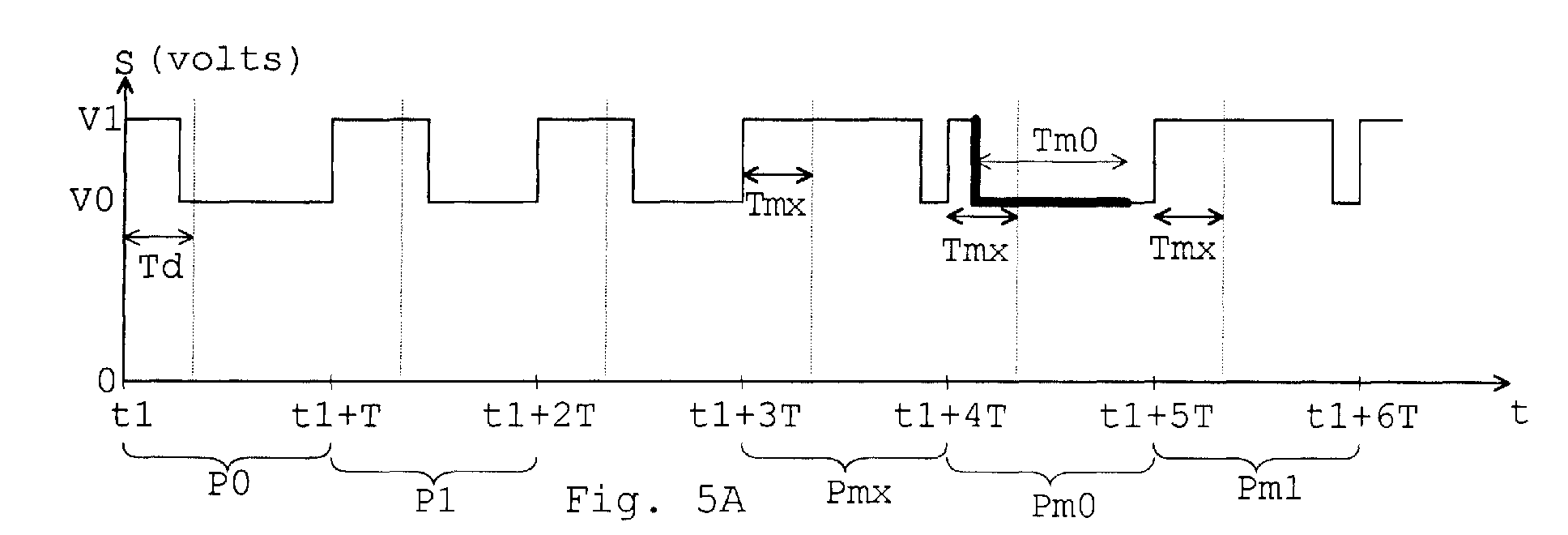
- Figure 5A shows an extract of a typical communication along the communication bus of the invention. The digital data transmitted by the communications bus of the invention is carried in a sequence of pulses varying between the voltages V0 and V1, visible in figure 2. To isolate these pulses, a voltage comparator may be used in the slave circuit M, with a threshold value set between V0 and V1.
- A signal out(t) shown in figure 5B may be produced by such a comparator, which translates a high voltage V1 on the signal conductor S to a high (1) value at approximately the supply level Vcm of the comparator; and a low voltage V0 on the signal conductor S to a low value (0) at approximately the voltage of ground conductor G.
- The signal on conductor S is so designed that each rising transition corresponds to a clocking edge, indicated by arrowheads on the rising edges in figure 5B. Thus, each 0 to 1 transition of the out(t) signal is at a fixed delay T from the previous one.
- Periods P0, P1 in figures 5A, 5B represent the transmission of data bits representing a 0 and a 1, respectively. Each period is of duration T, and lasts from a start time t1 until a time t1+T, and from time t1+T to time t1+2T, respectively.
- In period P0, a rising edge is present at instant t1 to indicate the beginning of a clock period. Signals out(t), S remain at their respective high values for a duration T0, then return to their respective low values. A subsequent period P1 begins at instant t1+T, one clock period T after the rising edge at t1.
- In period P1, a rising edge is present at instant t1+T, to indicate the beginning of a clock period. The signals S, out(t) remain at their respective high values for a duration T1, then return to their low values. Each of these periods P0, P1 transmits one bit of data. A subsequent period begins at instant t1+2T, one clock period T after the rising edge at t1+T.
- Interpretation of these signals is performed by the input interface MI of the slave circuit.
- The value of the signal out(t) is sampled at a delay Td after each clocking edge, at instants marked with a dotted line. Td is selected to be longer than T0 but shorter than T1, so the value of this sample gives the value of the data bit being transmitted: "0" for period P0 (at instant t1+Td) and "1" for period P1 (at instant t1+T+Td).
- As the data bus is bidirectional, provision must be made to allow the slave circuit M to transmit information to the master circuit µP. The signal S supplied by the master circuit must continue to send clocking edges on the data bus. From addressing and other data already sent to the slave circuit, the slave prepares itself to transmit data at the required instant. Period Pmx indicates an enabling signal voltage transmitted by the master circuit to allow the slave circuit to return data.
- Considering period Pmx of figures 5A, 5B, a rising edge occurs at time t1+3T, and the signals S, out(t) remain at a high value for a delay of Ts, which may be equal to, or preferably longer than time T1.
- In order to allow bidirectional communication over the data bus, the output interface µPO of the master circuit µP must present a high impedance for voltages between V0 and V1, but a low impedance for voltages of V0 and less, to ensure that the voltage of the signal conductor S does not fall below V0.
- Period Pm0 of figures 5A, 5B shows the signal on conductor S and signal out(t) provided by the slave circuit when the slave circuit transmits a 0. As a reply to out(t), a low impedance circuit in the slave circuit output interface MO pulls the line S to the value V0, a delay of Tm after the clocking edge t1+4T, for a length of time Tm0. This length of time Tm0 is chosen to expire after Ts. The pulling of the voltage of conductor S to a low value is indicated by a thickened line. This is possible, due to the output impedance of the master circuit, discussed earlier, which makes it easy for the slave to pull the signal conductor to the V0 level, but not below V0. When the slave wishes to transmit a 1, the slave simply leaves the enabling signal transmitted by master circuit as it is (as in period Pm1 of figures 5A, 5B). The master circuit samples the value of the signal S at a delay Tmx after the clocking edge. Tmx may be equal to the delay Td performed by the slave circuit before sampling the value of the signal conductor. The sample so taken each period represents the value (0, 1) of the data bit transmitted. The data thus transmitted from the slave circuit to the master circuit may be stored in serial data registers in the master circuit, assembled into words and then interpreted as appropriate. This continues until the slave has transmitted all the requested data. The slave circuit may send a certain specific code to indicate that its transmission is terminated, or the master circuit may simply cease to send enabling signals.
- In systems where several slave circuits are connected to the same data bus, chip select and deselect signals are needed to address each circuit.
- Figures 6A and 6B show the signals S and out(t) as used to transmit chip select and deselect signals. To indicate a chip select condition (period Psel), the voltage of the signal conductor S is held at the high voltage V1 for a period Tsel following a clocking edge at time t2. The period Tsel is preferably longer than a clock period T and shorter than two clock periods. The signal out(t) mirrors this with a 1 value during the period t2 to t2+Tsel.
- To indicate a chip deselect condition (period Pdes), the signal S becomes low, at voltage V0, at a delay Tr after the clocking edge at time t3, and remains low for a period Tdes. The delay Tr may be equal to delay T0 discussed earlier with reference to figures 5A, 5B. This is mirrored by signal out(t), as shown in figure 6B. The period Tdes is preferably longer than a clock period T and shorter than two clock periods. The signals S, out(t) remain at their low value until a subsequent clocking edge at time t3+2T. The select and deselect signal period Tsel, Tdes, may also be longer than two clock periods, but shorter than three clock periods, or other such lengths.
- For each select or deselect command, the slave circuit detects a missing clock edge at times t2+T, t3+T. The value of out(t) is sampled at a delay Tc after the last clock edge when a missing clock edge is detected, and the value of this sample indicates whether the signal is a chip select (1) or deselect (0). Serial data following a chip select command can be used to provide identification characters so that a required chip is selected. As the data bus can only communicate with one slave chip at a time, there is no need to send identification data with a deselect command. Simply, the previously selected chip becomes deselected.
- Figures 7 to 13 represent circuitry which may be used to realise the communications bus of the invention.
- Figure 7 shows a circuit suitable for use as a slave circuit supply voltage generating circuit MV. This circuit is a half wave rectifier and smoothing circuit. It comprises a resistor R1, a diode M1, or diode connected transistor and a capacitor C2 serially connected between the S and G conductors of the communications bus B.
- A series arrangement of transistors Q1, Q2, Q3, Q4 is connected between a common node F of M1 and C2, and the G conductor. These n-channel transistors are connected with the source of one connected to the gate and drain of the next; the source of Q4 being connected to conductor G and the gate and drain of Q1 being connected to node F.
- A further transistor M2 has its channel connected between the S conductor and the Vcm output; its gate is connected to node F. A yet further transistor M3 has its channel connected in parallel with that of M2, but its gate connected to the Vcm output. Transistors M2, M3 have approximately identical threshold voltages.
- The half wave rectifier and smoothing circuit M1, R1, C2 acts to provide a relatively constant voltage at node F, whose value lies between voltages V1 and V0. Transistors Q1, Q2, Q3, Q4 are diode connected, and act to maintain a constant voltage of about 3.3V at node F. These transistors may be increased or decreased in number according to their threshold voltages and the constant voltage required. Transistor M2 acts as a voltage follower. This maintains a threshold voltage between the Vcm output and node F, and provides a low impedance supply output, by providing a current path from S. The supply voltage Vcm is held at about 2.8V. The output Vcm is also held at about 2.8V by transistor M3 which provides current to the output Vcm directly from the S conductor.
- This circuit provides a relatively stable supply voltage Vcm, but at quite a low value.
- Figure 8 shows a first possible realisation of an input interface MI for the slave circuit. A voltage divider comprising resistances R2, R3 is placed between the S and G conductors of the communications bus. A capacitor C3 is placed between the G conductor and a common node F2 of the voltage divider. Node F2 is connected to a gate of a transistor Q5, whose channel is connected between the G conductor and a node X, in common with a first terminal of a source So of current i. An inverter INV has an input connected to this node X, and an output which is the interfaced signal out(t). The current i source So may simply be a high value resistor. The resistive divider is so designed that approximately one quarter of the voltage of the signal S is applied to the gate of Q5. Capacitor C3 acts as a noise filter in combination with resistors R2, R3. This filter preferably has a time constant of around 100ns. If, for example, R2 has a value of 300kW, and R3 has a value of 100kW, C3 will have a value of around 1pF. If S varies between 5V and 3V, the voltage at node F2 will vary between 1.25V and 0.75V. Q5 thus needs to be selected to have a threshold voltage of around 1V, so that the voltage at node X is high when S is at V0, and low when S is at V1.
- Figure 9 shows an alternative embodiment of the input interface MI of the slave circuit. Features common with figure 8 share common reference labels. Here, the resistor R2 and capacitor C3 connected between the S, G conductors of the communications bus have a common node F3. A number of diode connected transistors, for example two transistors Q6, Q7, are connected in series between node F3 and a further node Y. Node Y is connected to the gate of transistor Q5, and also connected through a current source I8 to the G conductor. Current source I8, may be a current mirror using MOS transistors, operated in saturated mode. Native n channel transistor Q8 is controlled by a gate voltage Vgi, supplied by a current mirror circuit (not shown). It may typically provide a current of 100µA.
- Capacitor C3 acts as a noise filter, in combination with resistor R2, and may have a value of about 1pF. Transistors Q6, Q7 may be p-channel native transistors, each having a threshold voltage of about 1.5V. The voltage at node Y is thus about 3V less than the voltage at node F3. It will vary between 2V and 0V, as conductor S varies between 5V and 3V, depending on the voltage across R2. Again, transistor Q5 acts to supply a high voltage at node X when S is low (V0), and a low voltage at node X when S is high (V1). Inverter INV rectifies the logic and provides a clean out(t) signal by a threshold action. The data so interfaced may be stored using a latch, activated once per period, according to the slave's clock signal, and the data bits so stored assembled together in a register for interpretation.
- Figure 10 shows a possible implementation of the output interface MO of the slave circuit M. A resistor R4 and an n channel MOS transistor T3 are respectively connected in series between the S and G conductors of the data bus. Data Sdm which is to be serially output is applied to a gate of a transistor T3, through an inverter INVA.
- When the slave circuit wishes to transmit a "0" bit, the inverter INVA applies a high voltage to the gate of T3. Transistor T3 becomes conductive, and the voltage of the S conductor approaches the voltage of the G conductor, due to the short circuiting effect of transistor T3, limited by resistor R4.
- When the slave circuit wishes to transmit a "1" bit, the inverter INVA applies a low voltage to the gate of T3. Transistor T3 is non-conductive, and the voltage of the S is unaffected.
- Figure 11 shows a possible implementation of the master circuit output interface µPO. The serial data signal Sdµ to be sent is applied, through an inverter INV2, to a gate of an MOS transistor M4. This transistor M4 is connected, in series with a resistor R5, between the two conductors S, G of the communications bus. A series of forward biased diodes D4a, D4b, D4c, are connected between the supply voltage Vcc and the S conductor. These diodes may be diode connected MOS transistors. A resistor R6 is connected in parallel with these diodes.
- When the value of Sdµ is low, the inverter will cause a high voltage to be present on the gate of transistor M4, rendering it conductive. The voltage of the S conductor will then be determined by the potential divider formed by resistors R5, R6. Conductor S will therefore be at Vcc/2 if R5 is approximately equal to R6, or about 2.5V for a 5V supply Vcc.
- When Sdµ is at a high level, this is inverted by inverter INV2 to apply a low voltage to the gate of transistor M4. This transistor becomes non-conductive, and the voltage of the S conductor rises to become Vcc due to the pull-up resistor R6. Forward biased diodes D4a, D4b, D4c maintain a value of about 3V on the S conductor in the event that a slave circuit should attempt to pull this conductor below this value. This circuit thus has the desired high output impedance between V1 and V0, and low output impedance for values below V0, as discussed earlier.
- Figure 12 shows one possible realisation of an input interface µPI of a master circuit. The signal conductor S is connected via a resistor R7 to a noninverting input of a comparator COM2. A resistive divider composed of resistors R8, R9 connected between Vcc and the ground conductor G has a central node N connected to an inverting input of the comparator COM2. An output of the comparator provides a serial data input signal in(t) for use by the master circuit. This signal is analogous to the signal out(t) already discussed, but for input to the master circuit. The resistive divider is designed so that R9 has a value approximately four times that of R8. As the G conductor is connected to the ground terminal of the master circuit, node N will have a voltage of around 4V.
- When the voltage of conductor S is above the voltage of node N, the output in(t) of the comparator will be high; when the voltage of conductor S is below this value, the output in(t) will be low. The master circuit will interpret the data so received by storing the signals in(t) in a shift register (for example).
- Decoding and interpretation of signals sent on the communications bus of the invention depends on accurate timing of sampling and generation of the voltage on conductor S. As clocking edges are continuously provided by the master circuit, the slave circuit only has to measure timing delays relative to the most recent clocking edge. The simplest way of achieving this is to use a timer which is reset at each clocking edge.
- Figure 13A shows a possible implementation of the timing circuit of the slave device. In this slave circuit, the slave circuit clock generator MC generates a clock signal CKM at, say, 2MHz to an input of a multistage counter CON comprising a series of latches L1 - L6. A rising-edge sensitive reset of each latch is connected to receive the out(t) signal. The clock CKM generator MC may be very simple, such as ring oscillator.
- As shown in figure 13B, output signals Co1-Co6 of each latch provide a first rising transition within 1, 2, 4, 8, 16, 32 periods of CKM, respectively, after being reset by each clocking edge of the out(t) signal. As the clocking edge of signal out(t) resets the counter CON, but does not synchronise the clock signal CKM, the transitions supplied by the latches may not be offset by an integral number of CKM clock periods after the clocking edge of signal out(t). Each of the latch output signals is used to time an event in the protocol of the invention. As each timed delay is relative to the most recent clocking edge of the signal out(t) provided by the master circuit, this timing circuit does not need to be especially accurate.
- Co1 provides a rising edge within 500ns after the clocking edge of the signal out(t) (for the 2MHz clock mentioned above). This may be used to time the delay Tm after which the S conductor may be pulled to its lower (V0) value, to transmit a "0" bit.
- Co2 provides a rising edge within 1µs after the clocking edge of the signal out(t). This may be used to time the delay Td for detection of 0 or 1 in a transmission from the master circuit.
- Co3 provides a rising edge within 2µs of the clocking edge of the signal out(t). This may be used to time the end T1 of the high (V1) voltage emitted by the master circuit as an enabling signal to allow the slave circuit to transmit data.
- Co4 provides a rising edge within 4µs of the clocking edge of the signal out(t). This may be used to time the end of the period Tm0 within which the slave circuit may pull the S conductor to its lower (V0) value.
- Co5 provides a rising edge within 8µs of the clocking edge of the signal out(t). This may be approximately equal to a clocking period T of the master circuit.
- Co6 provides a rising edge within 16µs of the clocking edge of the signal out(t). This may be significantly longer than a clock period, and may be used to time the delay Tc necessary to detect a chip select or deselect signal.
- The duration T0 of a pulse emitted by the master circuit in transmitting a "0" may be substantially equal to Tm.
- A very simple timer will normally suffice, as it is re-synchronised to the master circuit timing by every clocking edge of signal out(t). Although the timing used by the master circuit and the slave circuit should be substantially identical, a variation as great as 30-40% in the accuracy of the slave timer as compared to the master timer, may be tolerated. Such variation may among other things be due to process variation and ambient temperature changes. It is for this reason that each timed delay in the above example is twice as long as the previous timed delay. A series of monostables could be used as a timing circuit, or a PLL based timer, if higher accuracy is required.
- Figure 14 illustrates the possible contents of a bidirectional communication over the communications bus of the invention. Firstly, a chip select command is sent to enable a slave circuit. If many slave circuits are connected to the communications bus, a chip address may be sent after the select command, to identify which chip needs to be enabled. Then, an instruction may be sent (an "opcode"), followed by the address of the memory cell that the instruction needs to be carried out upon, followed by data needed to perform the instruction. The opcode-address-data sequence may be repeated many times to transfer all data or instructions required. To allow the slave circuit to transmit information to the master circuit, the opcode transfer may be replaced by enabling signals Pm0, Pm1 as described above in relation to figures 5A and 5B.
- The bidirectional two wire communications bus according to the invention may advantageously be used to communicate with tags embedded in articles. For example, cartridges filled with toner for use in printers may be provided with a tag, and a data bus according to the invention used to ensure communication between this tag and a host microprocessor, either within the printer or within a host computer. The tag may give information about the cartridge, its age, toner type, the amount of toner remaining and an identification code entered by the manufacturer. This information may be read by the host microprocessor to determine whether the correct type of cartridge is being used, whether enough toner is available for a requested print job, or whether the desired type of toner is present. The host microprocessor may give suitable warning messages to an operator.
- Similar considerations apply to tags for any low cost consumable or exchangeable component - battery packs, photographic film, even automotive components, where the combination of a low data rate together with very simple installation of the data bus and very inexpensive slave circuits makes such a solution attractive.
- Although described with reference to one specific embodiment, many variants of the communications bus are possible, and lie within the scope of the invention.
- In particular, the polarity and logical significance of the signals may be reversed; a negative supply voltage may be transmitted, the ground conductor G may be at a fixed voltage other than ground, or a differential signal may be transmitted on the two conductors S, G.
- Selection of transistors used as diodes depends on the polarity required, and the forward voltage drop required.
- The n channel MOS transistors used for switching could be replaced by equivalent npn bipolar transistors. Also, a p channel MOS or pnp bipolar could be used, if the polarity of the gate signals are inverted. Similarly for p channel MOS transistors used for switching.
- The clock signal derived from the rising edges may be supplied to a phase locked loop which generates a much higher clock frequency for the slave circuit's internal operation.
Claims (14)
- A method for encoding and transmitting a clock signal, a supply voltage and bidirectional digital data from a master circuit (µP) to a slave circuit (M), including the steps of:- holding a first conductor (S) at a first voltage (V0);- periodically raising the first conductor to a second voltage (V1), a fixed period (T) after a previous raising to the second voltage;- holding the first conductor at the second voltage for predetermined periods, then returning the first conductor to the first voltage;- controlling the predetermined periods to each have a logical significance;characterised in that the method further comprises the steps of:- holding a second conductor (G) at a third voltage (GND) different from the first and second voltages;- measuring the voltage of the first conductor at a temporal offset (Td, Tmx) with respect to the instant of said raising of said first conductor to a second voltage;- interpreting the measured voltage according to predetermined logical significances; and- raising the first conductor to the second voltage, this raising being used as a clock signal.
- A method according to claim 1 wherein one predetermined period signifies a "0" bit, and a second predetermined period signifies a "1" bit.
- A method according to any of claims 1 to 2 wherein the first conductor is held at one of first and second voltages for a period longer than the fixed period (T) to indicate a chip select command.
- A method according to any of the claims 1 to 3 wherein the first conductor is held at one of first and second voltages for a period longer than the fixed period (T) to indicate a chip deselect command.
- A method according to any of the claims 1 to 4 wherein, to allow the slave circuit to communicate, the master circuit emits a series of pulses on the first conductor at the second voltage, and that the slave circuit pulls the second conductor to a fourth voltage to indicate a first polarity of bit transmitted, and does not affect the voltage of the second conductor to indicate a second polarity of bit transmitted.
- A method according to claim 5 wherein the fourth voltage is equal to the first voltage.
- A method according to any of claims 1 to 6 wherein the voltage of the second conductor is not raised to the second voltage for an extended period exceeding the fixed period, and wherein this event is interpreted as a chip select or deselect signal, depending on the voltage present on the second conductor during this extended period.
- A data communications system including a master circuit (µP) comprising an output interface (µPO) and an input interface (µPI), a slave circuit (M) comprising an input interface (MI), an output interface (MO), a voltage generating circuit (MV) and a timing circuit (MC), a communications bus (B) comprising two conductors (S, G) only, the master circuit output interface holding a first conductor (S) at one of two predetermined potentials (V0, V1), characterised in that it comprises a circuit for bringing the potential of the first conductor regularly, repeatedly, and with a fixed period (T), to a second potential before returning to a first potential, and in that the first and second potentials are different from a third potential (GND) to which the second conductor is brought to provide a power supply to the slave circuit.
- A data communications system according to claim 8 wherein the master circuit output interface (µPO) has an output impedance for voltages between the first (V0) and second (V1) voltages substantially higher than its output impedance for voltages of magnitude inferior to the lower (V0) of the fist and second voltages.
- A data communications system according to claim 8 or claim 9, wherein the output interface (MO) of the slave circuit places a low impedance path between the first conductor and the second conductor to transmit a signal of a first polarity to the master circuit, and wherein the output interface of the slave circuit places no such low impedance patch between the first conductor and the second conductor to transmit a signal of second polarity to the master circuit.
- A data communications system according to any of claims 8 to 10 wherein the slave circuit timing circuit (MC) times a number of preset delays (Co1-Co6) from reception of each transition on the first conductor, and supplies a signal to the slave circuit input interface causing the voltage on the first conductor to be measured, by comparison with a predetermined reference value, which lies between the first voltage and the second voltage.
- An identification tag including a slave circuit comprising an input interface, an output interface, a timing circuit (MC) and a supply voltage generating circuit, the slave circuit being connected to two external conductors, deriving its power from a dc voltage that is continually present between the two conductors, the timing circuit timing delays relative to periodic changes in the voltage between the two conductors, the output interface providing a low impedance path between the two conductors to transmit a signal of a first polarity, and no such low impedance path to transmit a signal of second polarity.
- A toner cartridge for a printer containing an identification tag according to claim 12.
- A disposable item containing an identification tag according to claim 12.
Applications Claiming Priority (2)
| Application Number | Priority Date | Filing Date | Title |
|---|---|---|---|
| FR9603890 | 1996-03-28 | ||
| FR9603890A FR2746995B1 (en) | 1996-03-28 | 1996-03-28 | TRANSMISSION ENCODING METHOD AND DEVICE AND USE OF THE METHOD |
Publications (2)
| Publication Number | Publication Date |
|---|---|
| EP0798901A1 true EP0798901A1 (en) | 1997-10-01 |
| EP0798901B1 EP0798901B1 (en) | 1999-02-10 |
Family
ID=9490659
Family Applications (1)
| Application Number | Title | Priority Date | Filing Date |
|---|---|---|---|
| EP97400633A Expired - Lifetime EP0798901B1 (en) | 1996-03-28 | 1997-03-20 | Simultaneous transmission of power clock and data |
Country Status (5)
| Country | Link |
|---|---|
| US (1) | US5903607A (en) |
| EP (1) | EP0798901B1 (en) |
| JP (1) | JP3705312B2 (en) |
| DE (1) | DE69700112T2 (en) |
| FR (1) | FR2746995B1 (en) |
Cited By (15)
| Publication number | Priority date | Publication date | Assignee | Title |
|---|---|---|---|---|
| WO2000016525A1 (en) * | 1998-09-10 | 2000-03-23 | Silicon Image, Inc. | A system and method for sending and receiving data signals over a clock signal line |
| EP1612985A1 (en) * | 2004-06-30 | 2006-01-04 | Axalto SA | Bidirectional communication |
| WO2006043130A1 (en) * | 2004-07-28 | 2006-04-27 | Axalto Sa | Bidirectional communication |
| EP2146287A1 (en) | 2008-07-16 | 2010-01-20 | STMicroelectronics (Rousset) SAS | Interface between a two-wire bus and a single-wire bus |
| WO2010010278A1 (en) * | 2008-07-22 | 2010-01-28 | Stmicroelectronics (Rousset) Sas | Multichannel transmission on unifilar bus |
| FR2967510A1 (en) * | 2010-11-15 | 2012-05-18 | St Microelectronics Rousset | CONVERSION OF COMMUNICATION PROTOCOL ON A UNIFIL BUS |
| WO2013052886A3 (en) * | 2011-10-05 | 2013-11-21 | Analog Devices, Inc. | Two-wire communication system for high-speed data and power distribution |
| WO2014052122A1 (en) * | 2012-09-28 | 2014-04-03 | Osram Sylvania Inc. | Pulse-based binary communication |
| WO2014189636A1 (en) * | 2013-05-24 | 2014-11-27 | Apple Inc. | Interface for transferring time-sampled sensor data |
| US9160414B2 (en) | 2012-09-28 | 2015-10-13 | Osram Sylvania Inc. | Transient power communication |
| US9448959B2 (en) | 2012-10-05 | 2016-09-20 | Analog Devices, Inc. | Two-wire communication protocol engine |
| US9772665B2 (en) | 2012-10-05 | 2017-09-26 | Analog Devices, Inc. | Power switching in a two-wire conductor system |
| US9946679B2 (en) | 2011-10-05 | 2018-04-17 | Analog Devices, Inc. | Distributed audio coordination over a two-wire communication bus |
| FR3093199A1 (en) * | 2019-02-22 | 2020-08-28 | Stmicroelectronics (Grenoble 2) Sas | Signal modulation on the I2C bus |
| US11874791B2 (en) | 2011-10-05 | 2024-01-16 | Analog Devices, Inc. | Two-wire communication systems and applications |
Families Citing this family (151)
| Publication number | Priority date | Publication date | Assignee | Title |
|---|---|---|---|---|
| US7663780B2 (en) * | 1999-06-30 | 2010-02-16 | Silverbrook Research Pty Ltd | Cartridge with identifiers |
| US20050052661A1 (en) * | 1999-06-30 | 2005-03-10 | Paul Lapstun | Cartridge with identifiers |
| US7831244B2 (en) * | 1999-06-30 | 2010-11-09 | Silverbrook Research Pty Ltd | Retrieving an image via a coded surface |
| US7054399B1 (en) | 2000-09-29 | 2006-05-30 | Rockwell Automation Technologies, Inc. | Low overhead synchronized activation of functional modules |
| US10835307B2 (en) | 2001-06-12 | 2020-11-17 | Ethicon Llc | Modular battery powered handheld surgical instrument containing elongated multi-layered shaft |
| DE10315303B4 (en) * | 2003-04-02 | 2007-03-22 | Infineon Technologies Ag | Semiconductor device power supply for system with at least two, in particular stacked, semiconductor devices |
| KR100626364B1 (en) * | 2003-07-02 | 2006-09-20 | 삼성전자주식회사 | Semiconductor Package Having Multi-Chips |
| US8182501B2 (en) | 2004-02-27 | 2012-05-22 | Ethicon Endo-Surgery, Inc. | Ultrasonic surgical shears and method for sealing a blood vessel using same |
| EP1802245B8 (en) | 2004-10-08 | 2016-09-28 | Ethicon Endo-Surgery, LLC | Ultrasonic surgical instrument |
| US7190267B2 (en) * | 2004-12-30 | 2007-03-13 | Alliance Systems, Ltd. | System and method for managing power control and data communication among devices |
| DE102005008322B4 (en) * | 2005-02-23 | 2017-05-24 | Infineon Technologies Ag | Signal transmission arrangement and signal transmission method |
| US20070191713A1 (en) | 2005-10-14 | 2007-08-16 | Eichmann Stephen E | Ultrasonic device for cutting and coagulating |
| US7621930B2 (en) | 2006-01-20 | 2009-11-24 | Ethicon Endo-Surgery, Inc. | Ultrasound medical instrument having a medical ultrasonic blade |
| US8610478B1 (en) * | 2006-09-19 | 2013-12-17 | Cypress Semiconductor Corporation | Differential delay cell with low power, low jitter, and small area |
| US8226675B2 (en) | 2007-03-22 | 2012-07-24 | Ethicon Endo-Surgery, Inc. | Surgical instruments |
| US8142461B2 (en) | 2007-03-22 | 2012-03-27 | Ethicon Endo-Surgery, Inc. | Surgical instruments |
| US8911460B2 (en) | 2007-03-22 | 2014-12-16 | Ethicon Endo-Surgery, Inc. | Ultrasonic surgical instruments |
| US8057498B2 (en) | 2007-11-30 | 2011-11-15 | Ethicon Endo-Surgery, Inc. | Ultrasonic surgical instrument blades |
| US8808319B2 (en) | 2007-07-27 | 2014-08-19 | Ethicon Endo-Surgery, Inc. | Surgical instruments |
| US8523889B2 (en) | 2007-07-27 | 2013-09-03 | Ethicon Endo-Surgery, Inc. | Ultrasonic end effectors with increased active length |
| US8882791B2 (en) | 2007-07-27 | 2014-11-11 | Ethicon Endo-Surgery, Inc. | Ultrasonic surgical instruments |
| US9044261B2 (en) | 2007-07-31 | 2015-06-02 | Ethicon Endo-Surgery, Inc. | Temperature controlled ultrasonic surgical instruments |
| US8430898B2 (en) | 2007-07-31 | 2013-04-30 | Ethicon Endo-Surgery, Inc. | Ultrasonic surgical instruments |
| US8512365B2 (en) | 2007-07-31 | 2013-08-20 | Ethicon Endo-Surgery, Inc. | Surgical instruments |
| AU2008308606B2 (en) | 2007-10-05 | 2014-12-18 | Ethicon Endo-Surgery, Inc. | Ergonomic surgical instruments |
| US10010339B2 (en) | 2007-11-30 | 2018-07-03 | Ethicon Llc | Ultrasonic surgical blades |
| FR2929780A1 (en) | 2008-04-08 | 2009-10-09 | St Microelectronics Rousset | DETECTION OF DATA RECEIVED BY A MASTER DEVICE IN A SINGLE-AIR COMMUNICATION PROTOCOL |
| JP5145125B2 (en) * | 2008-06-11 | 2013-02-13 | 本田技研工業株式会社 | Magnet generator |
| US9089360B2 (en) | 2008-08-06 | 2015-07-28 | Ethicon Endo-Surgery, Inc. | Devices and techniques for cutting and coagulating tissue |
| US8248230B2 (en) * | 2009-02-20 | 2012-08-21 | Redwood Systems, Inc. | Smart power device |
| US8427300B2 (en) * | 2009-02-20 | 2013-04-23 | Redwood Systems, Inc. | Transmission of power and data with frequency modulation |
| US8207635B2 (en) * | 2009-02-20 | 2012-06-26 | Redwood Systems, Inc. | Digital switch communication |
| DE102009001081B3 (en) | 2009-02-23 | 2010-04-22 | Airbus Deutschland Gmbh | Device for transmitting data e.g. control data, and energy over e.g. network nodes, of Ethernet network in e.g. passenger aircraft, has supply unit supplying data-voltage signal to receiving line with supply voltage signals |
| US9700339B2 (en) | 2009-05-20 | 2017-07-11 | Ethicon Endo-Surgery, Inc. | Coupling arrangements and methods for attaching tools to ultrasonic surgical instruments |
| US8663220B2 (en) | 2009-07-15 | 2014-03-04 | Ethicon Endo-Surgery, Inc. | Ultrasonic surgical instruments |
| US10441345B2 (en) | 2009-10-09 | 2019-10-15 | Ethicon Llc | Surgical generator for ultrasonic and electrosurgical devices |
| US9168054B2 (en) | 2009-10-09 | 2015-10-27 | Ethicon Endo-Surgery, Inc. | Surgical generator for ultrasonic and electrosurgical devices |
| US11090104B2 (en) | 2009-10-09 | 2021-08-17 | Cilag Gmbh International | Surgical generator for ultrasonic and electrosurgical devices |
| USRE47996E1 (en) | 2009-10-09 | 2020-05-19 | Ethicon Llc | Surgical generator for ultrasonic and electrosurgical devices |
| US9039695B2 (en) | 2009-10-09 | 2015-05-26 | Ethicon Endo-Surgery, Inc. | Surgical generator for ultrasonic and electrosurgical devices |
| US8486096B2 (en) | 2010-02-11 | 2013-07-16 | Ethicon Endo-Surgery, Inc. | Dual purpose surgical instrument for cutting and coagulating tissue |
| US8961547B2 (en) | 2010-02-11 | 2015-02-24 | Ethicon Endo-Surgery, Inc. | Ultrasonic surgical instruments with moving cutting implement |
| US8951272B2 (en) | 2010-02-11 | 2015-02-10 | Ethicon Endo-Surgery, Inc. | Seal arrangements for ultrasonically powered surgical instruments |
| US8579928B2 (en) | 2010-02-11 | 2013-11-12 | Ethicon Endo-Surgery, Inc. | Outer sheath and blade arrangements for ultrasonic surgical instruments |
| US8469981B2 (en) | 2010-02-11 | 2013-06-25 | Ethicon Endo-Surgery, Inc. | Rotatable cutting implement arrangements for ultrasonic surgical instruments |
| GB2480498A (en) | 2010-05-21 | 2011-11-23 | Ethicon Endo Surgery Inc | Medical device comprising RF circuitry |
| US8795327B2 (en) | 2010-07-22 | 2014-08-05 | Ethicon Endo-Surgery, Inc. | Electrosurgical instrument with separate closure and cutting members |
| US9192431B2 (en) | 2010-07-23 | 2015-11-24 | Ethicon Endo-Surgery, Inc. | Electrosurgical cutting and sealing instrument |
| FR2963449B1 (en) * | 2010-07-27 | 2013-01-25 | St Microelectronics Rousset | CONVERSION OF A BIFILAR BUS IN A UNIFIL BUS |
| FR2963451B1 (en) | 2010-07-27 | 2012-12-07 | St Microelectronics Rousset | AUTHENTICATION OF MULTIPROTOCOL COMMUNICATION |
| FR2963519B1 (en) | 2010-07-27 | 2012-08-03 | St Microelectronics Rousset | COMMUNICATION PROTOCOL ON A UNIFIL BUS |
| US8775707B2 (en) | 2010-12-02 | 2014-07-08 | Blackberry Limited | Single wire bus system |
| US9259265B2 (en) | 2011-07-22 | 2016-02-16 | Ethicon Endo-Surgery, Llc | Surgical instruments for tensioning tissue |
| WO2013119545A1 (en) | 2012-02-10 | 2013-08-15 | Ethicon-Endo Surgery, Inc. | Robotically controlled surgical instrument |
| US9724118B2 (en) | 2012-04-09 | 2017-08-08 | Ethicon Endo-Surgery, Llc | Techniques for cutting and coagulating tissue for ultrasonic surgical instruments |
| US9439668B2 (en) | 2012-04-09 | 2016-09-13 | Ethicon Endo-Surgery, Llc | Switch arrangements for ultrasonic surgical instruments |
| US9226766B2 (en) * | 2012-04-09 | 2016-01-05 | Ethicon Endo-Surgery, Inc. | Serial communication protocol for medical device |
| US9237921B2 (en) | 2012-04-09 | 2016-01-19 | Ethicon Endo-Surgery, Inc. | Devices and techniques for cutting and coagulating tissue |
| US9241731B2 (en) | 2012-04-09 | 2016-01-26 | Ethicon Endo-Surgery, Inc. | Rotatable electrical connection for ultrasonic surgical instruments |
| US9479275B2 (en) | 2012-06-01 | 2016-10-25 | Blackberry Limited | Multiformat digital audio interface |
| CN104541473B (en) | 2012-06-01 | 2017-09-12 | 黑莓有限公司 | Being used for based on probabilistic method ensures the generic sync engine of the locking in multi-format audio system |
| US20140005705A1 (en) | 2012-06-29 | 2014-01-02 | Ethicon Endo-Surgery, Inc. | Surgical instruments with articulating shafts |
| US20140005702A1 (en) | 2012-06-29 | 2014-01-02 | Ethicon Endo-Surgery, Inc. | Ultrasonic surgical instruments with distally positioned transducers |
| US9820768B2 (en) | 2012-06-29 | 2017-11-21 | Ethicon Llc | Ultrasonic surgical instruments with control mechanisms |
| US9198714B2 (en) | 2012-06-29 | 2015-12-01 | Ethicon Endo-Surgery, Inc. | Haptic feedback devices for surgical robot |
| US9408622B2 (en) | 2012-06-29 | 2016-08-09 | Ethicon Endo-Surgery, Llc | Surgical instruments with articulating shafts |
| US9351754B2 (en) | 2012-06-29 | 2016-05-31 | Ethicon Endo-Surgery, Llc | Ultrasonic surgical instruments with distally positioned jaw assemblies |
| US9283045B2 (en) | 2012-06-29 | 2016-03-15 | Ethicon Endo-Surgery, Llc | Surgical instruments with fluid management system |
| US9226767B2 (en) | 2012-06-29 | 2016-01-05 | Ethicon Endo-Surgery, Inc. | Closed feedback control for electrosurgical device |
| US9393037B2 (en) | 2012-06-29 | 2016-07-19 | Ethicon Endo-Surgery, Llc | Surgical instruments with articulating shafts |
| US9326788B2 (en) | 2012-06-29 | 2016-05-03 | Ethicon Endo-Surgery, Llc | Lockout mechanism for use with robotic electrosurgical device |
| WO2014052181A1 (en) | 2012-09-28 | 2014-04-03 | Ethicon Endo-Surgery, Inc. | Multi-function bi-polar forceps |
| US9095367B2 (en) | 2012-10-22 | 2015-08-04 | Ethicon Endo-Surgery, Inc. | Flexible harmonic waveguides/blades for surgical instruments |
| US10201365B2 (en) | 2012-10-22 | 2019-02-12 | Ethicon Llc | Surgeon feedback sensing and display methods |
| US20140135804A1 (en) | 2012-11-15 | 2014-05-15 | Ethicon Endo-Surgery, Inc. | Ultrasonic and electrosurgical devices |
| US9461812B2 (en) | 2013-03-04 | 2016-10-04 | Blackberry Limited | Increased bandwidth encoding scheme |
| US10226273B2 (en) | 2013-03-14 | 2019-03-12 | Ethicon Llc | Mechanical fasteners for use with surgical energy devices |
| US9241728B2 (en) | 2013-03-15 | 2016-01-26 | Ethicon Endo-Surgery, Inc. | Surgical instrument with multiple clamping mechanisms |
| US9814514B2 (en) | 2013-09-13 | 2017-11-14 | Ethicon Llc | Electrosurgical (RF) medical instruments for cutting and coagulating tissue |
| US9265926B2 (en) | 2013-11-08 | 2016-02-23 | Ethicon Endo-Surgery, Llc | Electrosurgical devices |
| DE102013020954A1 (en) * | 2013-12-12 | 2015-06-18 | Northrop Grumman Litef Gmbh | Method and device for transmitting data at asynchronous transitions between domains with different clock frequencies |
| GB2521229A (en) | 2013-12-16 | 2015-06-17 | Ethicon Endo Surgery Inc | Medical device |
| GB2521228A (en) | 2013-12-16 | 2015-06-17 | Ethicon Endo Surgery Inc | Medical device |
| US9795436B2 (en) | 2014-01-07 | 2017-10-24 | Ethicon Llc | Harvesting energy from a surgical generator |
| US9554854B2 (en) | 2014-03-18 | 2017-01-31 | Ethicon Endo-Surgery, Llc | Detecting short circuits in electrosurgical medical devices |
| US10463421B2 (en) | 2014-03-27 | 2019-11-05 | Ethicon Llc | Two stage trigger, clamp and cut bipolar vessel sealer |
| US10092310B2 (en) | 2014-03-27 | 2018-10-09 | Ethicon Llc | Electrosurgical devices |
| US9737355B2 (en) | 2014-03-31 | 2017-08-22 | Ethicon Llc | Controlling impedance rise in electrosurgical medical devices |
| US9473876B2 (en) | 2014-03-31 | 2016-10-18 | Blackberry Limited | Method and system for tunneling messages between two or more devices using different communication protocols |
| US9913680B2 (en) | 2014-04-15 | 2018-03-13 | Ethicon Llc | Software algorithms for electrosurgical instruments |
| US10285724B2 (en) | 2014-07-31 | 2019-05-14 | Ethicon Llc | Actuation mechanisms and load adjustment assemblies for surgical instruments |
| DE102014116909B4 (en) * | 2014-11-19 | 2016-07-28 | Infineon Technologies Ag | A receiver, transmitter, method for retrieving an additional data value from a signal and method for transmitting a data value and an additional data value in a signal |
| FR3029661B1 (en) * | 2014-12-04 | 2016-12-09 | Stmicroelectronics Rousset | METHODS OF TRANSMITTING AND RECEIVING A BINARY SIGNAL OVER A SERIAL LINK, ESPECIALLY FOR DETECTING THE TRANSMISSION SPEED, AND DEVICES THEREOF |
| US10639092B2 (en) | 2014-12-08 | 2020-05-05 | Ethicon Llc | Electrode configurations for surgical instruments |
| US10245095B2 (en) | 2015-02-06 | 2019-04-02 | Ethicon Llc | Electrosurgical instrument with rotation and articulation mechanisms |
| US10342602B2 (en) | 2015-03-17 | 2019-07-09 | Ethicon Llc | Managing tissue treatment |
| US10321950B2 (en) | 2015-03-17 | 2019-06-18 | Ethicon Llc | Managing tissue treatment |
| US10595929B2 (en) | 2015-03-24 | 2020-03-24 | Ethicon Llc | Surgical instruments with firing system overload protection mechanisms |
| US10034684B2 (en) | 2015-06-15 | 2018-07-31 | Ethicon Llc | Apparatus and method for dissecting and coagulating tissue |
| US11020140B2 (en) | 2015-06-17 | 2021-06-01 | Cilag Gmbh International | Ultrasonic surgical blade for use with ultrasonic surgical instruments |
| US11129669B2 (en) | 2015-06-30 | 2021-09-28 | Cilag Gmbh International | Surgical system with user adaptable techniques based on tissue type |
| US11141213B2 (en) | 2015-06-30 | 2021-10-12 | Cilag Gmbh International | Surgical instrument with user adaptable techniques |
| US10898256B2 (en) | 2015-06-30 | 2021-01-26 | Ethicon Llc | Surgical system with user adaptable techniques based on tissue impedance |
| US10034704B2 (en) | 2015-06-30 | 2018-07-31 | Ethicon Llc | Surgical instrument with user adaptable algorithms |
| US10357303B2 (en) | 2015-06-30 | 2019-07-23 | Ethicon Llc | Translatable outer tube for sealing using shielded lap chole dissector |
| US11051873B2 (en) | 2015-06-30 | 2021-07-06 | Cilag Gmbh International | Surgical system with user adaptable techniques employing multiple energy modalities based on tissue parameters |
| US10154852B2 (en) | 2015-07-01 | 2018-12-18 | Ethicon Llc | Ultrasonic surgical blade with improved cutting and coagulation features |
| US10194973B2 (en) | 2015-09-30 | 2019-02-05 | Ethicon Llc | Generator for digitally generating electrical signal waveforms for electrosurgical and ultrasonic surgical instruments |
| US10595930B2 (en) | 2015-10-16 | 2020-03-24 | Ethicon Llc | Electrode wiping surgical device |
| US10179022B2 (en) | 2015-12-30 | 2019-01-15 | Ethicon Llc | Jaw position impedance limiter for electrosurgical instrument |
| US10575892B2 (en) | 2015-12-31 | 2020-03-03 | Ethicon Llc | Adapter for electrical surgical instruments |
| US10716615B2 (en) | 2016-01-15 | 2020-07-21 | Ethicon Llc | Modular battery powered handheld surgical instrument with curved end effectors having asymmetric engagement between jaw and blade |
| US11051840B2 (en) | 2016-01-15 | 2021-07-06 | Ethicon Llc | Modular battery powered handheld surgical instrument with reusable asymmetric handle housing |
| US11229471B2 (en) | 2016-01-15 | 2022-01-25 | Cilag Gmbh International | Modular battery powered handheld surgical instrument with selective application of energy based on tissue characterization |
| US11129670B2 (en) | 2016-01-15 | 2021-09-28 | Cilag Gmbh International | Modular battery powered handheld surgical instrument with selective application of energy based on button displacement, intensity, or local tissue characterization |
| US10555769B2 (en) | 2016-02-22 | 2020-02-11 | Ethicon Llc | Flexible circuits for electrosurgical instrument |
| US10702329B2 (en) | 2016-04-29 | 2020-07-07 | Ethicon Llc | Jaw structure with distal post for electrosurgical instruments |
| US10485607B2 (en) | 2016-04-29 | 2019-11-26 | Ethicon Llc | Jaw structure with distal closure for electrosurgical instruments |
| US10646269B2 (en) | 2016-04-29 | 2020-05-12 | Ethicon Llc | Non-linear jaw gap for electrosurgical instruments |
| US10456193B2 (en) | 2016-05-03 | 2019-10-29 | Ethicon Llc | Medical device with a bilateral jaw configuration for nerve stimulation |
| US10245064B2 (en) | 2016-07-12 | 2019-04-02 | Ethicon Llc | Ultrasonic surgical instrument with piezoelectric central lumen transducer |
| US10893883B2 (en) | 2016-07-13 | 2021-01-19 | Ethicon Llc | Ultrasonic assembly for use with ultrasonic surgical instruments |
| US10842522B2 (en) | 2016-07-15 | 2020-11-24 | Ethicon Llc | Ultrasonic surgical instruments having offset blades |
| US10376305B2 (en) | 2016-08-05 | 2019-08-13 | Ethicon Llc | Methods and systems for advanced harmonic energy |
| US10285723B2 (en) | 2016-08-09 | 2019-05-14 | Ethicon Llc | Ultrasonic surgical blade with improved heel portion |
| USD847990S1 (en) | 2016-08-16 | 2019-05-07 | Ethicon Llc | Surgical instrument |
| US10952759B2 (en) | 2016-08-25 | 2021-03-23 | Ethicon Llc | Tissue loading of a surgical instrument |
| US10828056B2 (en) | 2016-08-25 | 2020-11-10 | Ethicon Llc | Ultrasonic transducer to waveguide acoustic coupling, connections, and configurations |
| CN106326174B (en) * | 2016-08-31 | 2019-01-29 | 宋红波 | A kind of two line telecommunication circuits |
| US10603064B2 (en) | 2016-11-28 | 2020-03-31 | Ethicon Llc | Ultrasonic transducer |
| US11266430B2 (en) | 2016-11-29 | 2022-03-08 | Cilag Gmbh International | End effector control and calibration |
| US10820920B2 (en) | 2017-07-05 | 2020-11-03 | Ethicon Llc | Reusable ultrasonic medical devices and methods of their use |
| DE102018216127A1 (en) * | 2018-09-21 | 2020-03-26 | Robert Bosch Gmbh | Battery system and method for operating a battery system |
| US11392809B2 (en) | 2019-01-18 | 2022-07-19 | Hewlett-Packard Development Company, L.P. | Follower circuits for communication |
| US20210196349A1 (en) | 2019-12-30 | 2021-07-01 | Ethicon Llc | Electrosurgical instrument with flexible wiring assemblies |
| US11786291B2 (en) | 2019-12-30 | 2023-10-17 | Cilag Gmbh International | Deflectable support of RF energy electrode with respect to opposing ultrasonic blade |
| US11812957B2 (en) | 2019-12-30 | 2023-11-14 | Cilag Gmbh International | Surgical instrument comprising a signal interference resolution system |
| US11911063B2 (en) | 2019-12-30 | 2024-02-27 | Cilag Gmbh International | Techniques for detecting ultrasonic blade to electrode contact and reducing power to ultrasonic blade |
| US11937866B2 (en) | 2019-12-30 | 2024-03-26 | Cilag Gmbh International | Method for an electrosurgical procedure |
| US11950797B2 (en) | 2019-12-30 | 2024-04-09 | Cilag Gmbh International | Deflectable electrode with higher distal bias relative to proximal bias |
| US11944366B2 (en) | 2019-12-30 | 2024-04-02 | Cilag Gmbh International | Asymmetric segmented ultrasonic support pad for cooperative engagement with a movable RF electrode |
| US11660089B2 (en) | 2019-12-30 | 2023-05-30 | Cilag Gmbh International | Surgical instrument comprising a sensing system |
| US11452525B2 (en) | 2019-12-30 | 2022-09-27 | Cilag Gmbh International | Surgical instrument comprising an adjustment system |
| US11786294B2 (en) | 2019-12-30 | 2023-10-17 | Cilag Gmbh International | Control program for modular combination energy device |
| US11696776B2 (en) | 2019-12-30 | 2023-07-11 | Cilag Gmbh International | Articulatable surgical instrument |
| US20210196362A1 (en) | 2019-12-30 | 2021-07-01 | Ethicon Llc | Electrosurgical end effectors with thermally insulative and thermally conductive portions |
| US11707318B2 (en) | 2019-12-30 | 2023-07-25 | Cilag Gmbh International | Surgical instrument with jaw alignment features |
| US11937863B2 (en) | 2019-12-30 | 2024-03-26 | Cilag Gmbh International | Deflectable electrode with variable compression bias along the length of the deflectable electrode |
| US11779329B2 (en) | 2019-12-30 | 2023-10-10 | Cilag Gmbh International | Surgical instrument comprising a flex circuit including a sensor system |
| US11779387B2 (en) | 2019-12-30 | 2023-10-10 | Cilag Gmbh International | Clamp arm jaw to minimize tissue sticking and improve tissue control |
| CN113297109A (en) * | 2020-02-24 | 2021-08-24 | 上海复控华龙微系统技术有限公司 | Bus communication method and device and bus communication system |
Citations (5)
| Publication number | Priority date | Publication date | Assignee | Title |
|---|---|---|---|---|
| GB2072467A (en) * | 1979-08-29 | 1981-09-30 | Fuji Electric Co Ltd | Wire data transmission system |
| EP0134174A1 (en) * | 1983-08-19 | 1985-03-13 | LA DETECTION ELECTRONIQUE FRANCAISE PROTECBAT Société dite: | Method of transmitting messages between a central station and several remote stations |
| US4907222A (en) * | 1988-08-17 | 1990-03-06 | Nuvatec, Inc. | Vehicle multiplex system |
| US5140611A (en) * | 1989-09-29 | 1992-08-18 | Rockwell International Corporation | Pulse width modulated self-clocking and self-synchronizing data transmission and method for a telephonic communication network switching system |
| US5363405A (en) * | 1992-11-27 | 1994-11-08 | Chrysler Corporation | Vehicle communications network transceiver, bus driver therefor |
Family Cites Families (4)
| Publication number | Priority date | Publication date | Assignee | Title |
|---|---|---|---|---|
| US4507793A (en) * | 1982-12-17 | 1985-03-26 | Gte Automatic Electric Incorporated | Digital signal transmission system |
| CH674113A5 (en) * | 1987-09-09 | 1990-04-30 | Willemin Electronic S A | |
| FR2707024B1 (en) * | 1993-06-22 | 1995-09-01 | Suisse Electronique Microtech | |
| US5585744A (en) * | 1995-10-13 | 1996-12-17 | Cirrus Logic, Inc. | Circuits systems and methods for reducing power loss during transfer of data across a conductive line |
-
1996
- 1996-03-28 FR FR9603890A patent/FR2746995B1/en not_active Expired - Fee Related
-
1997
- 1997-03-20 DE DE69700112T patent/DE69700112T2/en not_active Expired - Fee Related
- 1997-03-20 EP EP97400633A patent/EP0798901B1/en not_active Expired - Lifetime
- 1997-03-27 US US08/824,962 patent/US5903607A/en not_active Expired - Lifetime
- 1997-03-28 JP JP09477597A patent/JP3705312B2/en not_active Expired - Fee Related
Patent Citations (5)
| Publication number | Priority date | Publication date | Assignee | Title |
|---|---|---|---|---|
| GB2072467A (en) * | 1979-08-29 | 1981-09-30 | Fuji Electric Co Ltd | Wire data transmission system |
| EP0134174A1 (en) * | 1983-08-19 | 1985-03-13 | LA DETECTION ELECTRONIQUE FRANCAISE PROTECBAT Société dite: | Method of transmitting messages between a central station and several remote stations |
| US4907222A (en) * | 1988-08-17 | 1990-03-06 | Nuvatec, Inc. | Vehicle multiplex system |
| US5140611A (en) * | 1989-09-29 | 1992-08-18 | Rockwell International Corporation | Pulse width modulated self-clocking and self-synchronizing data transmission and method for a telephonic communication network switching system |
| US5363405A (en) * | 1992-11-27 | 1994-11-08 | Chrysler Corporation | Vehicle communications network transceiver, bus driver therefor |
Cited By (29)
| Publication number | Priority date | Publication date | Assignee | Title |
|---|---|---|---|---|
| US6463092B1 (en) | 1998-09-10 | 2002-10-08 | Silicon Image, Inc. | System and method for sending and receiving data signals over a clock signal line |
| WO2000016525A1 (en) * | 1998-09-10 | 2000-03-23 | Silicon Image, Inc. | A system and method for sending and receiving data signals over a clock signal line |
| EP1612985A1 (en) * | 2004-06-30 | 2006-01-04 | Axalto SA | Bidirectional communication |
| US8804482B2 (en) | 2004-07-28 | 2014-08-12 | Gemalto Sa | Bidirectional communication |
| WO2006043130A1 (en) * | 2004-07-28 | 2006-04-27 | Axalto Sa | Bidirectional communication |
| US9325486B2 (en) | 2004-07-28 | 2016-04-26 | Gemalto Sa | Bidirectional communication |
| EP2146287A1 (en) | 2008-07-16 | 2010-01-20 | STMicroelectronics (Rousset) SAS | Interface between a two-wire bus and a single-wire bus |
| WO2010010278A1 (en) * | 2008-07-22 | 2010-01-28 | Stmicroelectronics (Rousset) Sas | Multichannel transmission on unifilar bus |
| FR2934390A1 (en) * | 2008-07-22 | 2010-01-29 | St Microelectronics Rousset | MULTICANAL TRANSMISSION ON A UNIFIL BUS |
| FR2967510A1 (en) * | 2010-11-15 | 2012-05-18 | St Microelectronics Rousset | CONVERSION OF COMMUNICATION PROTOCOL ON A UNIFIL BUS |
| US8943254B2 (en) | 2010-11-15 | 2015-01-27 | Stmicroelectronics (Rousset) Sas | Conversion of a single-wire bus communication protocol |
| US9875152B2 (en) | 2011-10-05 | 2018-01-23 | Analog Devices, Inc. | Methods for discovery, configuration, and coordinating data communications between master and slave devices in a communication system |
| US10311010B2 (en) | 2011-10-05 | 2019-06-04 | Analog Devices, Inc. | Two-wire communication systems and applications |
| CN103946829A (en) * | 2011-10-05 | 2014-07-23 | 美国亚德诺半导体公司 | Two-wire communication system for high-speed data and power distribution |
| US9417944B2 (en) | 2011-10-05 | 2016-08-16 | Analog Devices, Inc. | Two-wire communication system for high-speed data and power distribution |
| US11874791B2 (en) | 2011-10-05 | 2024-01-16 | Analog Devices, Inc. | Two-wire communication systems and applications |
| CN103946829B (en) * | 2011-10-05 | 2016-09-21 | 美国亚德诺半导体公司 | The dual-wire communications system distributed for high-speed data and electric power |
| EP4180981A1 (en) * | 2011-10-05 | 2023-05-17 | Analog Devices, Inc. | Two-wire communication system for high-speed data and power distribution |
| WO2013052886A3 (en) * | 2011-10-05 | 2013-11-21 | Analog Devices, Inc. | Two-wire communication system for high-speed data and power distribution |
| US9946679B2 (en) | 2011-10-05 | 2018-04-17 | Analog Devices, Inc. | Distributed audio coordination over a two-wire communication bus |
| US9065544B2 (en) | 2012-09-28 | 2015-06-23 | Osram Sylvania Inc. | Pulse-based binary communication |
| US9160414B2 (en) | 2012-09-28 | 2015-10-13 | Osram Sylvania Inc. | Transient power communication |
| WO2014052122A1 (en) * | 2012-09-28 | 2014-04-03 | Osram Sylvania Inc. | Pulse-based binary communication |
| US9949345B2 (en) | 2012-09-28 | 2018-04-17 | Osram Sylvania Inc. | Transient power communication |
| US9772665B2 (en) | 2012-10-05 | 2017-09-26 | Analog Devices, Inc. | Power switching in a two-wire conductor system |
| US9946680B2 (en) | 2012-10-05 | 2018-04-17 | Analog Devices, Inc. | Peripheral device diagnostics and control over a two-wire communication bus |
| US9448959B2 (en) | 2012-10-05 | 2016-09-20 | Analog Devices, Inc. | Two-wire communication protocol engine |
| WO2014189636A1 (en) * | 2013-05-24 | 2014-11-27 | Apple Inc. | Interface for transferring time-sampled sensor data |
| FR3093199A1 (en) * | 2019-02-22 | 2020-08-28 | Stmicroelectronics (Grenoble 2) Sas | Signal modulation on the I2C bus |
Also Published As
| Publication number | Publication date |
|---|---|
| JPH1051501A (en) | 1998-02-20 |
| JP3705312B2 (en) | 2005-10-12 |
| US5903607A (en) | 1999-05-11 |
| FR2746995A1 (en) | 1997-10-03 |
| DE69700112T2 (en) | 1999-06-17 |
| EP0798901B1 (en) | 1999-02-10 |
| DE69700112D1 (en) | 1999-03-25 |
| FR2746995B1 (en) | 1998-05-15 |
Similar Documents
| Publication | Publication Date | Title |
|---|---|---|
| EP0798901B1 (en) | Simultaneous transmission of power clock and data | |
| US7028105B2 (en) | Apparatus, method and signal set for monoline serial interface | |
| US7143215B2 (en) | Communicating with devices over a bus and negotiating the transfer rate over the same | |
| US8971206B2 (en) | Self synchronizing data communication method and device | |
| US7891868B2 (en) | Temperature sensor and semiconductor memory device using the same | |
| US7873858B2 (en) | Clock signal generation device and method | |
| JPH07143108A (en) | Data communication circuit | |
| EP2028606B1 (en) | Method for determining temperature from a transponder | |
| JP2002271878A (en) | Control/monitor signal transmission system | |
| CN112840387A (en) | PSI5 base current sampling in synchronous mode | |
| US20110309916A1 (en) | Circuit Arrangement and Method for Controlling Communication Between a Control Circuit and a Transmitter/Receiver Unit via a Supply Line | |
| US11489345B2 (en) | Controllers, charging cables, and systems and methods for identifying types of charging cables | |
| CN113242628A (en) | LED control system | |
| JPH0741232Y2 (en) | Asynchronous binary data communication circuit | |
| CN108809093B (en) | Method and apparatus for controlling power supply of processing unit | |
| EP0840956B1 (en) | Microcontroller having a minimal number of external components | |
| US11562796B2 (en) | Frequency-voltage conversion circuit, semiconductor device, and memory system | |
| CN101927602B (en) | Apparatus including power supply circuit | |
| US9645621B2 (en) | Single-pin command technique for mode selection and internal data access | |
| JP2917060B2 (en) | Data transmission / reception method and apparatus | |
| CN112448709B (en) | SWP main interface circuit and terminal | |
| JPH07170294A (en) | Serial data reception circuit | |
| US6483879B1 (en) | Compensating for initial signal interference exhibited by differential transmission lines | |
| US20200326763A1 (en) | Safe power up mechanism | |
| SU839021A1 (en) | Square-wave pulse shaper |
Legal Events
| Date | Code | Title | Description |
|---|---|---|---|
| PUAI | Public reference made under article 153(3) epc to a published international application that has entered the european phase |
Free format text: ORIGINAL CODE: 0009012 |
|
| AK | Designated contracting states |
Kind code of ref document: A1 Designated state(s): DE FR GB IT |
|
| 17P | Request for examination filed |
Effective date: 19970801 |
|
| 17Q | First examination report despatched |
Effective date: 19980119 |
|
| GRAG | Despatch of communication of intention to grant |
Free format text: ORIGINAL CODE: EPIDOS AGRA |
|
| GRAG | Despatch of communication of intention to grant |
Free format text: ORIGINAL CODE: EPIDOS AGRA |
|
| GRAH | Despatch of communication of intention to grant a patent |
Free format text: ORIGINAL CODE: EPIDOS IGRA |
|
| GRAH | Despatch of communication of intention to grant a patent |
Free format text: ORIGINAL CODE: EPIDOS IGRA |
|
| GRAA | (expected) grant |
Free format text: ORIGINAL CODE: 0009210 |
|
| RAP3 | Party data changed (applicant data changed or rights of an application transferred) |
Owner name: STMICROELECTRONICS S.A. |
|
| AK | Designated contracting states |
Kind code of ref document: B1 Designated state(s): DE FR GB IT |
|
| ET | Fr: translation filed | ||
| REF | Corresponds to: |
Ref document number: 69700112 Country of ref document: DE Date of ref document: 19990325 |
|
| ITF | It: translation for a ep patent filed |
Owner name: PORTA CHECCACCI & ASSOCIATI S.P.A. |
|
| PLBE | No opposition filed within time limit |
Free format text: ORIGINAL CODE: 0009261 |
|
| STAA | Information on the status of an ep patent application or granted ep patent |
Free format text: STATUS: NO OPPOSITION FILED WITHIN TIME LIMIT |
|
| 26N | No opposition filed | ||
| REG | Reference to a national code |
Ref country code: GB Ref legal event code: IF02 |
|
| PGFP | Annual fee paid to national office [announced via postgrant information from national office to epo] |
Ref country code: DE Payment date: 20050317 Year of fee payment: 9 |
|
| PGFP | Annual fee paid to national office [announced via postgrant information from national office to epo] |
Ref country code: IT Payment date: 20060331 Year of fee payment: 10 |
|
| PGFP | Annual fee paid to national office [announced via postgrant information from national office to epo] |
Ref country code: GB Payment date: 20060816 Year of fee payment: 10 |
|
| PGFP | Annual fee paid to national office [announced via postgrant information from national office to epo] |
Ref country code: FR Payment date: 20060825 Year of fee payment: 10 |
|
| PG25 | Lapsed in a contracting state [announced via postgrant information from national office to epo] |
Ref country code: DE Free format text: LAPSE BECAUSE OF NON-PAYMENT OF DUE FEES Effective date: 20061003 |
|
| GBPC | Gb: european patent ceased through non-payment of renewal fee |
Effective date: 20070320 |
|
| REG | Reference to a national code |
Ref country code: FR Ref legal event code: ST Effective date: 20071130 |
|
| PG25 | Lapsed in a contracting state [announced via postgrant information from national office to epo] |
Ref country code: GB Free format text: LAPSE BECAUSE OF NON-PAYMENT OF DUE FEES Effective date: 20070320 |
|
| PG25 | Lapsed in a contracting state [announced via postgrant information from national office to epo] |
Ref country code: FR Free format text: LAPSE BECAUSE OF NON-PAYMENT OF DUE FEES Effective date: 20070402 |
|
| PG25 | Lapsed in a contracting state [announced via postgrant information from national office to epo] |
Ref country code: IT Free format text: LAPSE BECAUSE OF NON-PAYMENT OF DUE FEES Effective date: 20070320 |