EP0798634A1 - Method and system for creating user interface independent programs - Google Patents
Method and system for creating user interface independent programs Download PDFInfo
- Publication number
- EP0798634A1 EP0798634A1 EP97103091A EP97103091A EP0798634A1 EP 0798634 A1 EP0798634 A1 EP 0798634A1 EP 97103091 A EP97103091 A EP 97103091A EP 97103091 A EP97103091 A EP 97103091A EP 0798634 A1 EP0798634 A1 EP 0798634A1
- Authority
- EP
- European Patent Office
- Prior art keywords
- logic
- agent
- user interface
- look
- widget
- Prior art date
- Legal status (The legal status is an assumption and is not a legal conclusion. Google has not performed a legal analysis and makes no representation as to the accuracy of the status listed.)
- Withdrawn
Links
Images


Classifications
-
- G—PHYSICS
- G06—COMPUTING; CALCULATING OR COUNTING
- G06F—ELECTRIC DIGITAL DATA PROCESSING
- G06F9/00—Arrangements for program control, e.g. control units
- G06F9/06—Arrangements for program control, e.g. control units using stored programs, i.e. using an internal store of processing equipment to receive or retain programs
- G06F9/44—Arrangements for executing specific programs
- G06F9/451—Execution arrangements for user interfaces
- G06F9/454—Multi-language systems; Localisation; Internationalisation
Definitions
- GUIs are more complex than traditional character-based interfaces and take more time and effort to design and program.
- GUIs are more expensive and take more time to develop than non-graphical, character-based user interfaces.
- the invention relates to a method of controlling the appearance and behavior of a display device in a data processing system, including the steps of:
- the environment in which the present invention is used encompasses a general distributed computing system 100, wherein general purpose computers, workstations, or personal computers are connected via communication links of various types, in a client-server arrangement, wherein programs and data, many in the form of objects, are made available and shared by various members of the system for execution and access by other members of the system.
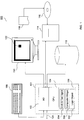
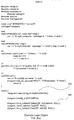
- Fig. 1 shows a processor 101, which has an input/output ("I/O") section 102, a central processing unit (“CPU"), 104, and a memory section 106.
- Memory section 106 includes a logic object 302, and a look and feel agent 304 (hereinafter "L&F” agent 114), and a composite Widget 306. Elements 302, 304, and 306 and their uses are discussed below in detail.
- the I/O section 102 is connected to a keyboard 108, a display unit 110, a disk storage unit 112, and a CD-ROM drive 114.
- CD-ROM drive 114 can read a CD-ROM medium 116, which typically contains programs 118 and data.
- a computer display icon 122 is shown on display unit 110.
- Similar workstations may be connected by a communications path 124 (e.g., an Ethernet network) to form a distributed computer system.
- a communications path 124 e.g., an Ethernet network
- the present invention is included as a part of Sun Microsystem's L10N Development Kit, version 2.0.
- the functionality of the L10N Development Kit which currently uses a graphical user interface, is intended to help computer programmers "localize" software products by tailoring certain aspects of the software products and manuals to various countries in which the software products and manuals are to be distributed.
- the present invention may be used with any software program that interfaces with a human being and is not limited to use with localization programs or with any particular type of computer software.
- the present invention is not limited to GUIs, but can integrate any type of user interface with the logic performing portion of a computer program.
- the present invention can be used to add a text-based user interface to a computer program.
- the described embodiment of the invention is written in the C++ programming language.
- C++ is an object-oriented language and, although the present invention will be described in terms of an object-oriented implementation, the present invention could also be implemented without using an object-oriented implementation.
- the described embodiment utilizes the Solaris operating system.
- Solaris is a version of the UNIX operating system that is manufactured by Sun Microsystems, Inc. Solaris is a trademark of Sun Microsystems, Inc. "UNIX" is a registered trademark in the United States and other countries, exclusively licensed through X/OPEN, Ltd.
- Fig. 2 is a representation of an object world 200 in a preferred embodiment of the present invention.
- the objects of Fig. 2 are classified into two types: logic objects 102, 104, 107, 108, 112, and 113 and L&F agents 106, 114, 115.
- Object-oriented programming is well-known to persons of ordinary skill in the art and will not be discussed in detail herein.
- objects and agents communicate by "object migration" as discussed below.
- logic objects provide the functionality of the system by performing localization functions.
- localization functions are examples of core logic functions.
- Fig. 2 shows a logic object 102 that performs the functions of "Navigator".
- the logic objects of Fig. 2 also include: "Dictionary Lookup” 107, “Translation Assistant” 112, "Install” 108, and "Glossary” 113.
- the specific nature of the core logic functions are not a part of the present invention and will not be discussed in detail.
- the present invention is directed to separation of the function of the core logic of logic objects from the user interface functions of L&F agent 114. This separation allows the logic objects to operate with L&F agents that implement various user interfaces.
- Fig. 3 is a block diagram showing a plurality of logic objects 102, 104 and 112 communicating with a plurality of L&F agents 114, 106 and 115.
- Each line 302 of Fig. 3 represents a connection established between a logic object and a L&F agent using "object migration," as discussed below. Lines 302 do not necessarily represent separate physical connections.
- Each L&F agent includes a plurality of composite widgets, each plurality represented by respective reference numbers 306, 308 and 310.
- a logic object communicates with a L&F agent via a "Distributed Object Management” (DOM) system 320.
- DOM Distributed Object Management
- This system passes objects containing predefined information between the logic objects and the L&F agents.
- a "Local Object Manager” (LOM) 330 in the DOM accesses configuration information 320.
- LOM 330 then initiates composite widgets in accordance with the configuration information.
- the LOM interfaces with the composite widgets, which perform GUI functions.
- Composite widgets 306, 308 and 310 are designed to operate with three different GUI's. Motif, OpenStep, and MS-Windows are shown in the Figure as examples.
- the LOM 330 is the same in agents 106, 114 and 115.
- multiple logic objects may act together as an individual process or as an individual thread within a process. Multiple logic objects may also act independently as separate threads or as separate processes.
- the system may contain any number of L&F agents, which interface to various GUI's. Respective L&F agents in the system may control different respective user interfaces at a given time. Some L&F agents may be on a different network node than all or some of the logic objects.
- L&F agent 114 is a service provider that handles the user interface (e.g., a GUI) for a client (a logic object). It is an important aspect of the present invention that the user interface is completely handled by the L&F agent.
- L&F agent 114 acts as a single server running on the user's workstation.
- at least one logic object such as delivery system logic object 102, functions as a window manager in an X Window system.
- a preferred embodiment of the present invention uses an object-oriented methodology. Specifically, the implementation may use DOE/DOMF (Distributed Objects Everywhere/Distributed Objects Messaging Format) to communicate between objects.
- DOE/DOMF Distributed Objects Everywhere/Distributed Objects Messaging Format
- L&F agent 114 creates and accesses a plurality of composite widgets 306.
- a "widget” is an object representing a display element, such as a requester box.
- the composite widgets of L&F agent 114 interface with Motif, revision 2.2 in accordance with configuration information 320. It should be understood by persons of ordinary skill in the art that other user interfaces can be used in place of Motif.
- the present invention can be used with OpenStep, with NextStep, with Windows-95, or with a text-based interface.
- Logic object 102 interfaces with L&F agent 114 for the following purposes:
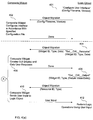
- Figs. 4(a) and 4(b) are diagrams showing steps performed by the logic object 102 and the L&F agent 114. It will be understood by persons of ordinary skill in the art that the steps of Fig. 4 are embodied by a CPU, such as CPU 104 of Fig. 1, that executes instructions stored in a memory of the computer system 100.
- a CPU such as CPU 104 of Fig. 1
- step 401 logic object 102 calls a "configure user interface" routine and passes it a name identifying the configuration information 320. This information is passed to L&F agent 114.
- LOM 314 reads and parses configuration information 320.
- Configuration information 320 which is discussed below in more detail, describes a screen layout of the user interface, a list of resources of widgets, and a list of reactions of the logic object to the user's actions. Exemplary user actions include pressing a button, selecting an item in a list, pressing a key, etc.
- LOM 314 then creates an internal widget list in memory 106 in accordance with the information.
- logic object 102 invokes a function "set_cw_resource" (set composite widget resource). The DOM of the logic object 102 migrates this information to the DOM of L&F agent 114.
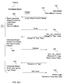
- Fig 4(b) shows an alternate embodiment of the present invention employing "call-backs" between the L&F agent and the logic object.
- steps 420-432 are performed instead of steps 406-412 of Fig. 4(a).
- logic object 102 calls a "bind-callback" function.
- the DOM of logic object 102 communicates the name of the logic objects callback function to the agent 114, which "binds" the logic object's call back function name to the name of an existing callback function in the agent.
- the DOM of the agent will also notify logic object 102 that a callback has occurred (see step 426).
- the logic object can then request the user input from the L&F agent 114, as discussed above in connection with Fig. 4(a).
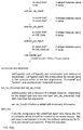
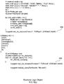
- Fig. 5 lists the calls that logic object 102 can issue to communicate with L&F agent 114. These calls include: bind_cb, set_cw_resource, set_cw_input, and display-GUI.
- Fig. 6 shows source code for an example logic object.
- the logic object calls "config_ui” at line 602; calls “bind_callback” at line 604, and calls set_cw_resource at lines 606.
- Fig. 7 is a flow chart of exemplary steps performed by an L&F agent.
- the L&F agent reads and parses configuration information 320 in step 702.
- the L&F agent instantiates composite widgets required to implement the GUI to be used.
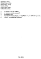
- Fig. 8 shows a syntax of configuration information 320.
- the configuration information preferably has three sections: a LAYOUT section, a RESOURCE section, and an ACTION section.
- Each section starts with a keyword (LAYOUT, RESOURCE or ACTION) followed by a colon.
- the LAYOUT section defines the type of the widgets used.
- the LAYOUT section includes one or more layout statements, each of which includes a widget ID, a class of the widget ID, either another widget ID or a widget tree.
- Fig. 10 shows exemplary widget classes.
- An example widget tree might look like:
- the widget name is more frequently used as configuration information than is the widget tree.
- the widget tree above is used by LOM 314 to construct a pull-down menu.
- the delivery subsystem of Fig. 12(b) has a menu button "File” with two subcategories, "deliver” and "quit”.
- "ROOT” is a reserved word in the configuration information 320 representing the root in the widget tree in the configuration information. Whether the widget class "actionMenuW" is rendered as a pull-down menu button or not is decided by the widget itself.
- the ACTION section of configuration information 320 defines actions to be taken upon actions by the human user. Some widgets may produce events which should be handled by the logic or any trigger value changes of other widgets. Logic may also expect results from widgets as it handles the event. These functionalities can be expressed in the following rules -
- the first rule tells L&F agent 114 that when an event comes from "action_widget_id", the event handler, "call-backID”, from the logic should be invoked with outputs from "output_widget_id” as arguments. Note that output_widget_ids are optional. The logic also needs to register the actual call-back function to L&F agent 114.
- Fig. 9 shows an example of configuration information in accordance with the syntax of Fig. 8.
- the configuration information includes a LAYOUT section 902, a resource Section 904, and an action section 906.
- Fig. 10 shows classes of composite widgets used that can be created by LOM 314 to be used with the Motif user interface.
- the classes of Fig. 10 are defined as follows:
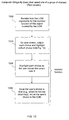
- Fig. 11 is a flow chart of steps performed by a first exemplary composite widget.
- Fig. 13 is a flow chart of steps performed by a second exemplary composite widget. From the viewpoint of logic object 102, the composite widgets of Figs. 11 and 13 perform exactly the same function: to display a list of choices and to allow the user to select one of the choices. In fact, however, the first composite widget implements a graphical user interface, while the second composite widget implements a text user interface. The difference between the two composite widgets is totally transparent to logic object 102.
- the LOM of L&F agent 114 initially instantiates one or the other of the objects of Figs. 11 and 13, in accordance with configuration information 320.
- Display area 1202 of Fig. 12 is generated by the steps of Fig. 11, which implements a graphical user interface.
- the composite widget receives from the LOM arguments for the member function invoked by the LOM.
- the member function outputs each choice with a small circle next to it.
- the member function allows the user to select one of the choices with, e.g., a mouse, and fills in the circle next to the selected choice.
- the member function once the user has made a final selection, as indicated by, e.g., double clicking the mouse button, the member function returns the user's choice to the LOM.
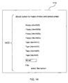
- Display area 1402 of Fig. 14 is generated by the steps of Fig. 13, which implements a text user interface.
- the second composite widget receives from the LOM arguments for the member function invoked by the LOM.
- the member function outputs each choice to the display screen. Note that the second composite widget does not interface with a windowing system, as does the composite widget of Figs. 11 and 12.
- the member function allows the user to select the choices by moving a cursor virtually using, e.g., keys on a keyboard. Each choice is highlighted as the cursor passes over it.
- step 1308 once the user has made a final selection, as indicated by, e.g., hitting the "return" key on the keyboard, the member function returns the user's choice to the LOM.
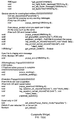
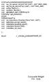
- Figs. 15(a) and 15(b) show an example composite widget.
- the composite widget shown is the widget to generate the main window in a windowing subsystem.
- the widget generates a menubar, a window body, and a footer area.
- a system in accordance with the present invention may contain any number of widgets in an L&F agent, and those widgets may perform any functionality required to generate a desired user interface.
- the widgets may implement any type of desired user interface, such as a graphical user interface or a text user interface.
- the type of user interface implemented is transparent to any logic objects interfacing with the L&F agent.
Abstract
An apparatus and method for separating the design and implementation of a user interface ("the user interface logic") from the design and implementation of the functional portion of a software program (the "core logic"). The present invention uses an object-oriented programming model in which one or more look and feel agents (304) act as servers for one or more logic objects (302). The look and feel agent (304) controls the appearance and behavior of the user interface, while logic objects (302) perform the functions of the software program. A look and feel agent (304) does not "know" what functions constitute the core logic and the logic objects (302) do not "know" what the user interface looks like or how it behaves.
Description
- This invention relates to generating a display on a computer screen and, more particularly, to a method and apparatus for separating the design and development of user interface functions from the design and development of core logic functions in a data processing system.
- A software program that is executed by a data processing system must have a way to "talk" to the world outside the computer system. For example, many software programs include a "graphical user interface" (GUI) that allows a human being using the software to give instructions to the software by moving a pointer on a display device with a mouse, a touchpad, or the like. The Windows operating system is an example of a software program that interfaces with the user via a GUI. ("Windows" is a trademark of Microsoft, Inc.) Another example of an operating system that uses a GUI is the OpenLook operating system, which is manufactured by Sun Microsystems. "OpenLook" is a trademark or a registered trademark in the U.S. and foreign countries of Sun Microsystems. Another example of an operating system that uses a GUI is the OpenStep operating system, which is manufactured by Next, Inc. "OpenStep" is a trademark of Next, Inc.
- It is desirable for software programs to use GUIs when interfacing with human users because human users find GUIs easier to use than traditional character-based computer interfaces. As a rule, however, GUIs are more complex than traditional character-based interfaces and take more time and effort to design and program. Thus, GUIs are more expensive and take more time to develop than non-graphical, character-based user interfaces.
- Generally speaking, software that uses a GUI performs several functions. First, the software must be able to display elements on the display device and must be able to adjust the displayed information in response to actions by the user, such as the user moving a cursor on the display device with a mouse. This function is an example of a "user interface function." Second, the software must be able to perform the actions indicated by the user via the user interface (such as performing one of a list of optional functions chosen by the user). These functions are examples of "core logic" functions. Conventionally, software programs have contained both user interface functions and core logic functions. For example, within a single software program, a core logic function might make calls to a user interface function that opens a new window on the display device. In such conventional programs, the call to the user interface function (where the call includes the name of the user interface function) is an integral part of the core logic.
- Most software is designed to operate with a single GUI. For example, the Microsoft "Windows" operating system expects to operate using a conventional Windows GUI. The GUI used with Windows will always look a certain way and there is no provision within Windows to use a different GUI. Modifying a program written to run under Windows to use a different GUI would involve extensive modifications to the core logic of the program. In other words, software programs written to run under Windows is tied to the Windows GUI and cannot be easily changed.
- It is desirable to be able to use any user interface with any software program. If the software program can operate with any user interface, the design of the user interface can be changed at will without having to change the core logic of the software program itself. Such a scheme would, for example, allow one or more GUIs to be developed independently of the core logic of the software program without impacting the design or complexity of the core logic of the software program. In addition, it would be easy to use different GUIs under different circumstances, since the only time involved in switching between GUIs would be the time required to develop or install the new GUI itself. No changes to the core logic of the software program would be required.
- As discussed above, conventional software programs mix user interface functions and core logic functions and intertwine the operation of the two types of functions. Another problem arising from the mixing of user interface functions and core logic functions is that certain computer programmers are expert at writing computer programs for user interface functions or for logic functions, but not for both. Adding a different user interface to a software program is a problem for a computer programmer who is expert in core logic programming but who is not expert in user interface programming. Similarly, if the user interface logic is too closely tied to the core logic, it creates problems for a programmer who is expert in user interface programming, but not in core logic programming.
- Conventional software sometimes allows a software program to operate with different user interfaces. This usually is accomplished by re-linking the core logic software so that it is linked to run with a new user interface. Before the relinking process can be performed, the core logic must be modified to refer to the new user interface. In other conventional software, the software is able to access a common "Application Program Interface" (API) layer that allows the software to use one of a plurality of user interfaces. In this case, however, the software program controls which user interface it uses and controls the initial selection of that user interface within the API. Thus, the functionality of the core logic is not completely separate from the choice and functionality of the user interface
- The present invention provides an apparatus and method for separating the design and implementation of a user interface from the design and implementation of the functional portion of a software program (the "core logic"). The present invention uses an object-oriented programming model in which one or more "look and feel agents" (hereinafter "L&F agents") act as servers for one or more logic object clients. A L&F agent controls the appearance and behavior of the user interface, while a logic object performs the functions of the software program. A L&F agent does not "know" what functions constitute the core logic and the core logic does not "know" what the user interface looks like or how it behaves.
- In accordance with the purpose of the invention, as embodied and broadly described herein, the invention relates to a method of controlling the appearance and behavior of a display device in a data processing system, including the steps of:
- defining by a look and feel agent, an appearance of a widget using configuration information that is not a part of the look and feel agent; and
- performing, by a core logic object, a core logic function;
- determining, by the core logic object during performance of the core logic function, that data must be displayed on the display device;
- sending information from the core logic object to the look and feel agent, the data representing the data to be displayed; and
- displaying, by the widgets of the look and feel agent, the data sent by the core logic object.
- The objects, features, and advantages of the system of the present invention will be apparent from the following description, in which:
- Fig. 1 illustrates an exemplary computer system in accordance with a preferred embodiment of the present invention.
- Fig. 2 is a representation of an "object world" in a preferred embodiment of the present invention.
- Fig. 3 is a block diagram showing a plurality of logic objects communicating with a plurality of look and feel agents of Fig. 2.
- Figs. 4(a) and 4(b) are diagrams showing steps performed by an exemplary logic object and an exemplary look and feel agent to communicate with a user through a GUI.
- Figs. 5(a) through 5(c) show exemplary functions called by the logic object of Fig. 3 to interface between the logic object and the look and feel agent.
- Fig. 6 shows source code for an example logic object.
- Fig. 7 is a flow chart of exemplary steps performed by a look and feel agent.
- Fig. 8 shows a syntax of configuration information used by the look and feel agent.
- Fig. 9 shows an example of configuration information in accordance with Fig. 8.
- Fig. 10 shows an example of classes of widgets created by the look and feel agent of Fig. 3.
- Fig. 11 is a flow chart of steps performed by a first exemplary composite widget.
- Fig. 12(a) shows an example of a window displayed in accordance with the example configuration information of Fig. 9 and the steps of Fig. 11.
- Fig. 12(b) shows an example of a pull-down menu in the window of Fig. 10.
- Fig. 13 is a flow chart of steps performed by a second exemplary composite widget.
- Fig. 14 shows an example of a screen display generated in accordance with the steps of Fig. 13.
- Fig. 15(a)-15(c) show an example of a composite widget.
- The following description is of the best presently contemplated modes of carrying out the invention. This description is made for the purpose of illustrating the general principles of the invention and is not to be taken in a limiting sense.
- The environment in which the present invention is used encompasses a general distributed
computing system 100, wherein general purpose computers, workstations, or personal computers are connected via communication links of various types, in a client-server arrangement, wherein programs and data, many in the form of objects, are made available and shared by various members of the system for execution and access by other members of the system. - Some of the elements of a general purpose workstation computer are shown in Fig. 1. Fig. 1 shows a
processor 101, which has an input/output ("I/O")section 102, a central processing unit ("CPU"), 104, and amemory section 106.Memory section 106 includes alogic object 302, and a look and feel agent 304 (hereinafter "L&F" agent 114), and acomposite Widget 306.Elements O section 102 is connected to akeyboard 108, adisplay unit 110, adisk storage unit 112, and a CD-ROM drive 114. CD-ROM drive 114 can read a CD-ROM medium 116, which typically containsprograms 118 and data. Acomputer display icon 122 is shown ondisplay unit 110. Similar workstations may be connected by a communications path 124 (e.g., an Ethernet network) to form a distributed computer system. - The present invention is included as a part of Sun Microsystem's L10N Development Kit, version 2.0. The functionality of the L10N Development Kit, which currently uses a graphical user interface, is intended to help computer programmers "localize" software products by tailoring certain aspects of the software products and manuals to various countries in which the software products and manuals are to be distributed. The present invention, however, may be used with any software program that interfaces with a human being and is not limited to use with localization programs or with any particular type of computer software. Moreover, the present invention is not limited to GUIs, but can integrate any type of user interface with the logic performing portion of a computer program. For example, the present invention can be used to add a text-based user interface to a computer program.
- The described embodiment of the invention is written in the C++ programming language. C++ is an object-oriented language and, although the present invention will be described in terms of an object-oriented implementation, the present invention could also be implemented without using an object-oriented implementation. The described embodiment utilizes the Solaris operating system. Solaris is a version of the UNIX operating system that is manufactured by Sun Microsystems, Inc. Solaris is a trademark of Sun Microsystems, Inc. "UNIX" is a registered trademark in the United States and other countries, exclusively licensed through X/OPEN, Ltd.
- Fig. 2 is a representation of an
object world 200 in a preferred embodiment of the present invention. The objects of Fig. 2 are classified into two types: logic objects 102, 104, 107, 108, 112, and 113 andL&F agents - In the described embodiment, logic objects provide the functionality of the system by performing localization functions. In this embodiment, localization functions are examples of core logic functions. For example, Fig. 2 shows a
logic object 102 that performs the functions of "Navigator". The logic objects of Fig. 2 also include: "Dictionary Lookup" 107, "Translation Assistant" 112, "Install" 108, and "Glossary" 113. The specific nature of the core logic functions are not a part of the present invention and will not be discussed in detail. The present invention is directed to separation of the function of the core logic of logic objects from the user interface functions ofL&F agent 114. This separation allows the logic objects to operate with L&F agents that implement various user interfaces. - Fig. 3 is a block diagram showing a plurality of logic objects 102, 104 and 112 communicating with a plurality of
L&F agents line 302 of Fig. 3 represents a connection established between a logic object and a L&F agent using "object migration," as discussed below.Lines 302 do not necessarily represent separate physical connections. Each L&F agent includes a plurality of composite widgets, each plurality represented byrespective reference numbers - A logic object communicates with a L&F agent via a "Distributed Object Management" (DOM)
system 320. This system passes objects containing predefined information between the logic objects and the L&F agents. In each L&F agent, a "Local Object Manager" (LOM) 330 in the DOM accessesconfiguration information 320. TheLOM 330 then initiates composite widgets in accordance with the configuration information. The LOM interfaces with the composite widgets, which perform GUI functions.Composite widgets LOM 330 is the same inagents - In the present invention, multiple logic objects may act together as an individual process or as an individual thread within a process. Multiple logic objects may also act independently as separate threads or as separate processes. The system may contain any number of L&F agents, which interface to various GUI's. Respective L&F agents in the system may control different respective user interfaces at a given time. Some L&F agents may be on a different network node than all or some of the logic objects.
- The following paragraphs discuss
L&F agent 114 andlogic object 102, although the discussion is equally applicable to any L&F agent and to any logic object in the system.L&F agent 114 is a service provider that handles the user interface (e.g., a GUI) for a client (a logic object). It is an important aspect of the present invention that the user interface is completely handled by the L&F agent. - The appearance and behavior of the user interface is entirely controlled by the L&F agent, as described in detail below.
L&F agent 114 is a "service provider" for the logic objects. The logic objects interface withL&F agent 114 for visual feedback, interactive input from a human being, and any other user-related tasks. The logic objects send requests toL&F agent 114 for visual feedback on GUI events that require a user's attention.L&F agent 114 receives interaction from a human via the user interface, converts the interaction to a functional request, and sends the functional request to an appropriate logic object. Thus, the logic object does not "know" what GUI is being used. - In the described embodiment,
L&F agent 114 acts as a single server running on the user's workstation. Similarly, at least one logic object, such as deliverysystem logic object 102, functions as a window manager in an X Window system. As discussed above, a preferred embodiment of the present invention uses an object-oriented methodology. Specifically, the implementation may use DOE/DOMF (Distributed Objects Everywhere/Distributed Objects Messaging Format) to communicate between objects. -
L&F agent 114 creates and accesses a plurality ofcomposite widgets 306. A "widget" is an object representing a display element, such as a requester box. In the described embodiment, the composite widgets ofL&F agent 114 interface with Motif, revision 2.2 in accordance withconfiguration information 320. It should be understood by persons of ordinary skill in the art that other user interfaces can be used in place of Motif. For example, the present invention can be used with OpenStep, with NextStep, with Windows-95, or with a text-based interface. -
Logic object 102 interfaces withL&F agent 114 for the following purposes: - 1. Physical communication between the agent and the logic object.
- 2. Instance name binding. Each display element is considered an "instance" of a type of display object.
Logic object 102 starts the display of a display element by binding a new instance name for the display element to display symbols stored in as associatedconfiguration information 320.Configuration information 320 is discussed in more detail in connection with Fig. 9. - 3. Upstream message handling. Besides the instance/name binding, the logic objects sends messages needed to build the look of and feel of the objects, such as a list of the choices in a particular data format.
- 4. Downstream message handling. In certain implementations a logic object may request a callback (at the time that it initiates an object), where the callback is to be performed, e.g., when the user clicks on a choice in a list of choices. If
logic object 102 requires a "callback",L&F agent 114 interfaces its own callbacks registered to the composite widget layer ofL&F agent 114. - 5. Managing multiple contexts of logic objects. Each L&F agent can communicate with multiple logic objects.
- 6. Define look and feel policy. Because
logic object 102 does not have any look and feel policy,L&F agent 114 defines such a policy from theexternal configuration information 320 associated with theL&F agent 114.Configuration information 320 is discussed in more detail in connection with Fig. 9. - Figs. 4(a) and 4(b) are diagrams showing steps performed by the
logic object 102 and theL&F agent 114. It will be understood by persons of ordinary skill in the art that the steps of Fig. 4 are embodied by a CPU, such asCPU 104 of Fig. 1, that executes instructions stored in a memory of thecomputer system 100. - In
step 401,logic object 102 calls a "configure user interface" routine and passes it a name identifying theconfiguration information 320. This information is passed toL&F agent 114. - In
step 402,LOM 314 reads and parsesconfiguration information 320.Configuration information 320, which is discussed below in more detail, describes a screen layout of the user interface, a list of resources of widgets, and a list of reactions of the logic object to the user's actions. Exemplary user actions include pressing a button, selecting an item in a list, pressing a key, etc.LOM 314 then creates an internal widget list inmemory 106 in accordance with the information. Instep 404logic object 102 invokes a function "set_cw_resource" (set composite widget resource). The DOM of thelogic object 102 migrates this information to the DOM ofL&F agent 114.LOM 314 searches its internal "instantiated" widget list (not shown) for a widget ID specified in the set_cw_resource function. Instep 406,LOM 314 invokes the proper member function of the proper composite widget and passes the resource data received from the logic object and the configuration information to the widget. - After the user indicates that his input is complete, the composite widget passes the user input to
L&F agent 114. TheL&F agent 114 notifies thelogic object 102.Logic object 102 invokes a look and feel function "get_cw_output" ("get composite widget output,") instep 408.L&F agent 114 searches its internal "instantiated widget list" instep 410 for a widget ID specified in the get_cw_output function.LOM 314 then gets the requested information from the composite widget and, instep 410, returns the information or data to the callinglogic object 102. - Fig 4(b) shows an alternate embodiment of the present invention employing "call-backs" between the L&F agent and the logic object. In this embodiment, steps 420-432 are performed instead of steps 406-412 of Fig. 4(a). In
step 420,logic object 102 calls a "bind-callback" function. The DOM oflogic object 102 communicates the name of the logic objects callback function to theagent 114, which "binds" the logic object's call back function name to the name of an existing callback function in the agent. - Thereafter, whenever the user performs an action that has been defined in the L&F agent to invoke the agent's callback function the DOM of the agent will also notify
logic object 102 that a callback has occurred (see step 426). The logic object can then request the user input from theL&F agent 114, as discussed above in connection with Fig. 4(a). - Fig. 5 lists the calls that
logic object 102 can issue to communicate withL&F agent 114. These calls include: bind_cb, set_cw_resource, set_cw_input, and display-GUI. - Fig. 6 shows source code for an example logic object. The logic object calls "config_ui" at
line 602; calls "bind_callback" atline 604, and calls set_cw_resource atlines 606. - Fig. 7 is a flow chart of exemplary steps performed by an L&F agent. Initially, the L&F agent reads and parses
configuration information 320 instep 702. Instep 704, in accordance with the configuration information, the L&F agent instantiates composite widgets required to implement the GUI to be used. - If, in
step 706, the L&F agent receives a set_cw_resource request, the L&F agent searches its "instantiated widget list" instep 708 for a widget that performs the function in the request. Instep 710, the L&F agent invokes the proper member function of the composite widget. The resource data in the request is passed as an argument to the invocation of the member function. - If, in
step 712, the L&F agent receives a get_cw_output request, the L&F agent searches its "instantiated widget list" instep 714 for a widget that performs the function in the request. Instep 716, the L&F agent invokes the proper member function of the composite widget and receives data from the composite widget. Instep 718, the L&G agent returns the received data to the logic object. In step 720, the L&F agent notifies the logic object of any user action that requires a reaction from the logic object. - Fig. 8 shows a syntax of
configuration information 320. As shown in Fig. 8 at 702, the configuration information preferably has three sections: a LAYOUT section, a RESOURCE section, and an ACTION section. Each section starts with a keyword (LAYOUT, RESOURCE or ACTION) followed by a colon. The LAYOUT section defines the type of the widgets used. The LAYOUT section includes one or more layout statements, each of which includes a widget ID, a class of the widget ID, either another widget ID or a widget tree. Fig. 10 shows exemplary widget classes. An example widget tree might look like:
- The widget name is more frequently used as configuration information than is the widget tree. The widget tree above is used by
LOM 314 to construct a pull-down menu. For example, the delivery subsystem of Fig. 12(b) has a menu button "File" with two subcategories, "deliver" and "quit". Note that "ROOT" is a reserved word in theconfiguration information 320 representing the root in the widget tree in the configuration information. Whether the widget class "actionMenuW" is rendered as a pull-down menu button or not is decided by the widget itself. - The RESOURCE section of
configuration information 320 has one or more resource statements of the form:
widget_id.resource: value - For example, for "load.label: Load Glossary" the action-Menu "load" has a label "Load Glossary".
- The ACTION section of
configuration information 320 defines actions to be taken upon actions by the human user. Some widgets may produce events which should be handled by the logic or any trigger value changes of other widgets. Logic may also expect results from widgets as it handles the event. These functionalities can be expressed in the following rules -
- The first rule tells
L&F agent 114 that when an event comes from "action_widget_id", the event handler, "call-backID", from the logic should be invoked with outputs from "output_widget_id" as arguments. Note that output_widget_ids are optional. The logic also needs to register the actual call-back function toL&F agent 114. - With the second format the source of the affected widget is set to the specified value. It is legal to specify more than one event handler as well as affected widgets. The invoking sequence depends on the appearance in the configuration information.
- Fig. 9 shows an example of configuration information in accordance with the syntax of Fig. 8. The configuration information includes a
LAYOUT section 902, aresource Section 904, and anaction section 906. - As discussed above, the LOM of
L&F agent 114 instantiates composite widgets in accordance withconfiguration information 320. Fig. 10 shows classes of composite widgets used that can be created byLOM 314 to be used with the Motif user interface. The classes of Fig. 10 are defined as follows: - CWObj:
The CWObj class is the top of the Composite Widget Set tree. The CWObj class is the only class with no superclass. The CWObj class is defined as pure virtual class, it is only to be inherited by the every classes in Composite Widget. - CWMain Frame:
The CWMainFrame class provides the frame with menu bar and message area. The CWMainFrame must be created as base window for all logic objects. - CWTextMsgDF:
This class contains message area, textfield and confirm buttons. It corresponds to PromptDialog Widget. - CWPullMenu:
The CRPullMenu class provides a PullDown menu, label and textfield area. - CWMenu:
The CWMenu class is to add extra menu to the menubar part of the CWMainFrame class. The CWMenu class consists of Pulldown menu, cascade buttons, and a label. - CWBrowser:
It contains two Selection Box Widgets with two buttons attached to each of the Boxes. It also contains three Label Widgets. The Label widgets are used for the title of the two selection widgets, the label for the left selection widget, and the third is for the right selection widget. - CWHierarchyBrowser:
Subclass of CWBrowser. In addition to CWBrowser class, CWHierarchyBrowser class provides the hierarchical data handling scheme listed in the Selection Box. It takes a tree structure containing multiple objects as a initialization input, and returns a list of objects being selected. - CWListBrowser:
Subclass of CWBrowser. In addition to CWBrowser class, CWListBrowser class provides the list data handling scheme displayed in the Selection Box. It takes a list structure containing multiple objects as an initialization input, and returns an objects being selected. - CWMessage:
MessageDialog class. This class contains message area and confirm buttons. - CWTextEdit:
Multi line editable text class. - CWSelRadioD:
This class consists of dialog widget that contains message area, radio buttons for selections, and confirm buttons. It will have BulletinBoard for the body parts. - Fig. 11 is a flow chart of steps performed by a first exemplary composite widget. Fig. 13 is a flow chart of steps performed by a second exemplary composite widget. From the viewpoint of
logic object 102, the composite widgets of Figs. 11 and 13 perform exactly the same function: to display a list of choices and to allow the user to select one of the choices. In fact, however, the first composite widget implements a graphical user interface, while the second composite widget implements a text user interface. The difference between the two composite widgets is totally transparent tologic object 102. The LOM ofL&F agent 114 initially instantiates one or the other of the objects of Figs. 11 and 13, in accordance withconfiguration information 320. -
Display area 1202 of Fig. 12 is generated by the steps of Fig. 11, which implements a graphical user interface. Instep 1102, the composite widget receives from the LOM arguments for the member function invoked by the LOM. Instep 1104, the member function outputs each choice with a small circle next to it. Instep 1106, the member function allows the user to select one of the choices with, e.g., a mouse, and fills in the circle next to the selected choice. Instep 1108, once the user has made a final selection, as indicated by, e.g., double clicking the mouse button, the member function returns the user's choice to the LOM. -
Display area 1402 of Fig. 14 is generated by the steps of Fig. 13, which implements a text user interface. Instep 1302, the second composite widget receives from the LOM arguments for the member function invoked by the LOM. Instep 1304, the member function outputs each choice to the display screen. Note that the second composite widget does not interface with a windowing system, as does the composite widget of Figs. 11 and 12. Instep 1306, the member function allows the user to select the choices by moving a cursor virtually using, e.g., keys on a keyboard. Each choice is highlighted as the cursor passes over it. Instep 1308, once the user has made a final selection, as indicated by, e.g., hitting the "return" key on the keyboard, the member function returns the user's choice to the LOM. - Figs. 15(a) and 15(b) show an example composite widget. The composite widget shown is the widget to generate the main window in a windowing subsystem. Thus, the widget generates a menubar, a window body, and a footer area.
- As will be understood by persons of ordinary skill in the art, a system in accordance with the present invention may contain any number of widgets in an L&F agent, and those widgets may perform any functionality required to generate a desired user interface. As discussed above, the widgets may implement any type of desired user interface, such as a graphical user interface or a text user interface. The type of user interface implemented is transparent to any logic objects interfacing with the L&F agent.
- Several preferred embodiments of the present invention have been described. Nevertheless, it will be understood that various modifications may be made without departing from the spirit and scope of the invention.
- In describing the preferred embodiment, a number of specific technologies used to implement the embodiments of various aspects of the invention were identified and related to more general terms in which the invention was described. However, it should be understood that such specificity is not intended to limit the scope of the claimed invention.
Claims (7)
- A method of controlling the appearance and behavior of a display device in a data processing system, including the steps of:defining, by a look and feel agent, an appearance of a widget using configuration information that is not a part of the look and feel agent; andperforming, by a core logic object, a core logic function;determining, by the core logic object during performance of the core logic function, that data must be displayed on the display device;sending information from the core logic object to the look and feel agent, the data representing the data to be displayed; anddisplaying, by the widgets of the look and feel agent, the data sent by the core logic object.
- The method of claim 1, further including the step of returning control by the look and feel agent to the core logic object when the look and feel agent receives a callback from the widget.
- The method of claim 1, wherein the configuration information has a layout section, a resource section, and an action section.
- The method of claim 1, wherein the sending step includes the step of migrating objects between the core logic object and the look and feel agent.
- The method of claim 1, further including the steps of:defining, by a second look and feel agent, a second widget using second configuration information that is not a part of the second look and feel agent and that is different from the first configuration information.
- The method of claim 1, wherein the configuration information corresponds to a first user interface.
- The method of claim 5, wherein the second configuration information corresponds to a second user interface.
Applications Claiming Priority (2)
| Application Number | Priority Date | Filing Date | Title |
|---|---|---|---|
| US08/607,939 US5754173A (en) | 1996-02-28 | 1996-02-28 | Method and system for creating user interface independent programs with a user interface provider |
| US607939 | 1996-02-28 |
Publications (1)
| Publication Number | Publication Date |
|---|---|
| EP0798634A1 true EP0798634A1 (en) | 1997-10-01 |
Family
ID=24434338
Family Applications (1)
| Application Number | Title | Priority Date | Filing Date |
|---|---|---|---|
| EP97103091A Withdrawn EP0798634A1 (en) | 1996-02-28 | 1997-02-26 | Method and system for creating user interface independent programs |
Country Status (3)
| Country | Link |
|---|---|
| US (1) | US5754173A (en) |
| EP (1) | EP0798634A1 (en) |
| JP (1) | JPH1049327A (en) |
Cited By (21)
| Publication number | Priority date | Publication date | Assignee | Title |
|---|---|---|---|---|
| GB2329494A (en) * | 1997-08-22 | 1999-03-24 | Ibm | Information processing for graphical user interface |
| WO1999034284A1 (en) * | 1997-12-31 | 1999-07-08 | Honeywell Inc. | Dynamic interface synthesizer |
| EP0944007A2 (en) * | 1998-02-24 | 1999-09-22 | Sun Microsystems, Inc. | Method and apparatus for generating text components in a graphical user interface |
| WO2001027748A2 (en) * | 1999-10-11 | 2001-04-19 | I2 Technologies, Inc. | Workflow encapsulation in stateless environments |
| EP1098246A1 (en) * | 1999-11-02 | 2001-05-09 | CANAL+ Société Anonyme | Displaying graphical objects |
| WO2001033344A2 (en) * | 1999-11-02 | 2001-05-10 | Canal+ Societe Anonyme | Displaying graphical objects |
| WO2001050257A2 (en) * | 2000-01-03 | 2001-07-12 | Wizion.Com, Inc. | Incorporating non-native user interface mechanisms into a user interface |
| WO2001075596A1 (en) * | 2000-03-31 | 2001-10-11 | British Telecommunications Public Limited Company | User interface for data acquisition |
| WO2002042908A1 (en) * | 2000-11-27 | 2002-05-30 | Nokia Corporation | Method and system providing a mediation function |
| WO2003005189A2 (en) * | 2001-07-06 | 2003-01-16 | Convergys Cmg Utah | Method for creating browser-based user interface applications using a framework |
| WO2003028827A2 (en) * | 2001-09-28 | 2003-04-10 | Igt | Decoupling of the graphical presentation of a game from the presentation logic |
| WO2003028828A2 (en) * | 2001-09-28 | 2003-04-10 | Igt | Game development architecture that decouples the game logic from the graphics logic |
| WO2003046722A2 (en) * | 2001-11-21 | 2003-06-05 | International Business Machines Corporation | Enhancing resource adapters |
| EP1403765A1 (en) * | 2002-09-25 | 2004-03-31 | Sap Ag | Method and computer system for event handling |
| US20080163202A1 (en) * | 1999-04-26 | 2008-07-03 | Mainstream Scientific, Llc | Server Including Components for Accessing and Displaying Internet Content and for Providing Same to a Client |
| US7461382B2 (en) | 2002-09-30 | 2008-12-02 | Sap Ag | Event handling with action instances for event-driven software application |
| US7657554B2 (en) * | 2004-11-05 | 2010-02-02 | Microsoft Corporation | Method and system for managing user interface messages |
| US7783040B2 (en) | 2000-03-08 | 2010-08-24 | Igt | Encryption in a secure computerized gaming system |
| US7918730B2 (en) | 2002-06-27 | 2011-04-05 | Igt | Trajectory-based 3-D games of chance for video gaming machines |
| US7988559B2 (en) | 2001-03-08 | 2011-08-02 | Igt | Computerized gaming system, method and apparatus |
| US8708828B2 (en) | 2001-09-28 | 2014-04-29 | Igt | Pluggable modular gaming modifiers and configuration templates for gaming environments |
Families Citing this family (73)
| Publication number | Priority date | Publication date | Assignee | Title |
|---|---|---|---|---|
| US6243102B1 (en) | 1994-05-16 | 2001-06-05 | Apple Computer, Inc. | Data-driven layout engine |
| US6404433B1 (en) | 1994-05-16 | 2002-06-11 | Apple Computer, Inc. | Data-driven layout engine |
| US5937187A (en) * | 1996-07-01 | 1999-08-10 | Sun Microsystems, Inc. | Method and apparatus for execution and preemption control of computer process entities |
| US6064382A (en) * | 1997-11-19 | 2000-05-16 | International Business Machines Corporation | Object oriented apparatus and method for providing a graphical user interface for host-based software applications |
| US7062773B1 (en) * | 1998-07-20 | 2006-06-13 | International Business Machines Corporation | System and method for providing graphical user interface control enhancers |
| US6493735B1 (en) * | 1998-12-15 | 2002-12-10 | International Business Machines Corporation | Method system and computer program product for storing bi-directional language data in a text string object for display on non-bidirectional operating systems |
| US6469713B2 (en) | 1998-12-15 | 2002-10-22 | International Business Machines Corporation | Method, system and computer program product for dynamic language switching via messaging |
| US6396515B1 (en) | 1998-12-15 | 2002-05-28 | International Business Machines Corporation | Method, system and computer program product for dynamic language switching in user interface menus, help text, and dialogs |
| GB2346291B (en) | 1999-01-26 | 2004-01-21 | Ericsson Telefon Ab L M | Handling menu information |
| US7821503B2 (en) | 2003-04-09 | 2010-10-26 | Tegic Communications, Inc. | Touch screen and graphical user interface |
| US7750891B2 (en) | 2003-04-09 | 2010-07-06 | Tegic Communications, Inc. | Selective input system based on tracking of motion parameters of an input device |
| US7030863B2 (en) * | 2000-05-26 | 2006-04-18 | America Online, Incorporated | Virtual keyboard system with automatic correction |
| US7286115B2 (en) | 2000-05-26 | 2007-10-23 | Tegic Communications, Inc. | Directional input system with automatic correction |
| ES2211234T3 (en) | 1999-06-04 | 2004-07-01 | Open Tv, Inc. | FLEXIBLE INTERFACE FOR THE SECURE ENTRY OF A PERSONALIZED IDENTIFICATION CODE. |
| US7100195B1 (en) | 1999-07-30 | 2006-08-29 | Accenture Llp | Managing user information on an e-commerce system |
| US6601233B1 (en) | 1999-07-30 | 2003-07-29 | Accenture Llp | Business components framework |
| US6704873B1 (en) | 1999-07-30 | 2004-03-09 | Accenture Llp | Secure gateway interconnection in an e-commerce based environment |
| US6718535B1 (en) | 1999-07-30 | 2004-04-06 | Accenture Llp | System, method and article of manufacture for an activity framework design in an e-commerce based environment |
| US8380490B1 (en) * | 1999-09-28 | 2013-02-19 | International Business Machines Corporation | Reusable controls for automatically translating text between languages |
| US6725424B1 (en) | 1999-12-09 | 2004-04-20 | International Business Machines Corp. | Electronic document delivery system employing distributed document object model (DOM) based transcoding and providing assistive technology support |
| US6829746B1 (en) | 1999-12-09 | 2004-12-07 | International Business Machines Corp. | Electronic document delivery system employing distributed document object model (DOM) based transcoding |
| US7054952B1 (en) | 1999-12-09 | 2006-05-30 | International Business Machines Corp. | Electronic document delivery system employing distributed document object model (DOM) based transcoding and providing interactive javascript support |
| US6738951B1 (en) * | 1999-12-09 | 2004-05-18 | International Business Machines Corp. | Transcoding system for delivering electronic documents to a device having a braille display |
| US6971086B2 (en) * | 2000-03-16 | 2005-11-29 | Silicon Graphics, Inc. | Common user interface development toolkit for a system administration program |
| US7123700B1 (en) * | 2000-04-27 | 2006-10-17 | Nortel Networks Limited | Configuring user interfaces of call devices |
| US6581186B1 (en) * | 2000-05-31 | 2003-06-17 | Xilinx, Inc. | Methods and systems for providing logic cores from third party logic core providers |
| US6918091B2 (en) * | 2000-11-09 | 2005-07-12 | Change Tools, Inc. | User definable interface system, method and computer program product |
| US7895530B2 (en) * | 2000-11-09 | 2011-02-22 | Change Tools, Inc. | User definable interface system, method, support tools, and computer program product |
| US8505024B2 (en) | 2000-12-18 | 2013-08-06 | Shaw Parsing Llc | Storing state in a dynamic content routing network |
| US7051070B2 (en) | 2000-12-18 | 2006-05-23 | Timothy Tuttle | Asynchronous messaging using a node specialization architecture in the dynamic routing network |
| US7587669B2 (en) * | 2001-04-09 | 2009-09-08 | Aol Llc | Server-based browser system |
| US6907451B1 (en) * | 2001-09-29 | 2005-06-14 | Siebel Systems, Inc. | Method, apparatus, and system for immediate posting of changes in a client server environment |
| US8359335B2 (en) | 2001-09-29 | 2013-01-22 | Siebel Systems, Inc. | Computing system and method to implicitly commit unsaved data for a world wide web application |
| US7203948B2 (en) * | 2001-09-29 | 2007-04-10 | Siebel Systems, Inc. | Method, apparatus, and system for implementing caching of view custom options in a framework to support web-based applications |
| US7461119B2 (en) * | 2001-09-29 | 2008-12-02 | Siebel Systems, Inc. | Method, apparatus, and system for managing status of requests in a client server environment |
| US7885996B2 (en) * | 2001-09-29 | 2011-02-08 | Siebel Systems, Inc. | Method, apparatus, and system for implementing notifications in a framework to support web-based applications |
| US7146617B2 (en) * | 2001-09-29 | 2006-12-05 | Siebel Systems, Inc. | Method, apparatus, and system for implementing view caching in a framework to support web-based applications |
| US7870492B2 (en) | 2001-10-02 | 2011-01-11 | Siebel Systems, Inc. | Method, apparatus, and system for managing commands in a client server environment |
| US7177793B2 (en) * | 2002-01-14 | 2007-02-13 | International Business Machines Corporation | System and method for managing translatable strings displayed on console interfaces |
| US7065744B2 (en) | 2002-01-14 | 2006-06-20 | International Business Machines Corporation | System and method for converting management models to specific console interfaces |
| US7240326B2 (en) * | 2002-01-14 | 2007-07-03 | International Business Machines Corporation | System and method for obtaining display names from management models |
| US20030135661A1 (en) * | 2002-01-14 | 2003-07-17 | International Business Machines Corporation | System and method for packaging and installing management models with specific console interfaces |
| US7191404B2 (en) * | 2002-01-14 | 2007-03-13 | International Business Machines Corporation | System and method for mapping management objects to console neutral user interface |
| CN100390731C (en) * | 2002-03-07 | 2008-05-28 | 霍尼韦尔国际公司 | Interaction design system |
| US20030197728A1 (en) * | 2002-04-17 | 2003-10-23 | Saravanan | Software personality wizard for ticket machines |
| US7076766B2 (en) | 2002-06-03 | 2006-07-11 | Steve Wirts | Software application development methods and framework |
| US20040015537A1 (en) * | 2002-07-15 | 2004-01-22 | Richard Doerksen | Handheld client framework system |
| US8682636B2 (en) * | 2002-08-30 | 2014-03-25 | Sap Ag | Non-client-specific testing of applications |
| JP4084225B2 (en) * | 2003-03-28 | 2008-04-30 | 富士通株式会社 | Service provision system |
| US20050193069A1 (en) * | 2004-02-26 | 2005-09-01 | International Business Machines Corporation | Providing a portion of an electronic mail message based upon a transfer rate and a message size |
| US7596285B2 (en) * | 2004-02-26 | 2009-09-29 | International Business Machines Corporation | Providing a portion of an electronic mail message at a reduced resolution |
| US7512658B2 (en) * | 2004-02-26 | 2009-03-31 | International Business Machines Corporation | Providing a portion of an electronic mail message based upon a transfer rate, a message size, and a file format |
| US7617501B2 (en) | 2004-07-09 | 2009-11-10 | Quest Software, Inc. | Apparatus, system, and method for managing policies on a computer having a foreign operating system |
| US9471332B2 (en) * | 2004-10-19 | 2016-10-18 | International Business Machines Corporation | Selecting graphical component types at runtime |
| US8307336B1 (en) * | 2005-03-30 | 2012-11-06 | Oracle America, Inc. | Mechanism for enabling a set of output from a functional component to be presented on different types of clients |
| US7849165B2 (en) | 2005-04-21 | 2010-12-07 | Fiducci Thomas E | Data backup, storage, transfer, and retrieval system, method and computer program product |
| US8126990B2 (en) | 2005-04-21 | 2012-02-28 | Fiducci Thomas E | Data backup and transfer system, method and computer program product |
| US20070106496A1 (en) * | 2005-11-09 | 2007-05-10 | Microsoft Corporation | Adaptive task framework |
| US7822699B2 (en) * | 2005-11-30 | 2010-10-26 | Microsoft Corporation | Adaptive semantic reasoning engine |
| US7606700B2 (en) * | 2005-11-09 | 2009-10-20 | Microsoft Corporation | Adaptive task framework |
| US7831585B2 (en) * | 2005-12-05 | 2010-11-09 | Microsoft Corporation | Employment of task framework for advertising |
| US20070130134A1 (en) * | 2005-12-05 | 2007-06-07 | Microsoft Corporation | Natural-language enabling arbitrary web forms |
| US7933914B2 (en) * | 2005-12-05 | 2011-04-26 | Microsoft Corporation | Automatic task creation and execution using browser helper objects |
| US7904949B2 (en) | 2005-12-19 | 2011-03-08 | Quest Software, Inc. | Apparatus, systems and methods to provide authentication services to a legacy application |
| US8087075B2 (en) | 2006-02-13 | 2011-12-27 | Quest Software, Inc. | Disconnected credential validation using pre-fetched service tickets |
| US7996783B2 (en) * | 2006-03-02 | 2011-08-09 | Microsoft Corporation | Widget searching utilizing task framework |
| US8429712B2 (en) | 2006-06-08 | 2013-04-23 | Quest Software, Inc. | Centralized user authentication system apparatus and method |
| US7681135B2 (en) * | 2006-08-10 | 2010-03-16 | Kabushiki Kaisha Toshiba | System and method for generating a composite source user interface |
| US7895332B2 (en) * | 2006-10-30 | 2011-02-22 | Quest Software, Inc. | Identity migration system apparatus and method |
| US8086710B2 (en) | 2006-10-30 | 2011-12-27 | Quest Software, Inc. | Identity migration apparatus and method |
| US8225203B2 (en) | 2007-02-01 | 2012-07-17 | Nuance Communications, Inc. | Spell-check for a keyboard system with automatic correction |
| US8201087B2 (en) | 2007-02-01 | 2012-06-12 | Tegic Communications, Inc. | Spell-check for a keyboard system with automatic correction |
| US8255984B1 (en) | 2009-07-01 | 2012-08-28 | Quest Software, Inc. | Single sign-on system for shared resource environments |
Citations (2)
| Publication number | Priority date | Publication date | Assignee | Title |
|---|---|---|---|---|
| EP0569902A2 (en) * | 1992-05-11 | 1993-11-18 | Softis Hf | User interface system for computers |
| EP0622729A2 (en) * | 1993-04-29 | 1994-11-02 | International Business Machines Corporation | A user interface builder for a user interface server |
Family Cites Families (8)
| Publication number | Priority date | Publication date | Assignee | Title |
|---|---|---|---|---|
| US5040131A (en) * | 1987-12-23 | 1991-08-13 | International Business Machines Corporation | Graphical processing |
| AU617006B2 (en) * | 1988-09-29 | 1991-11-14 | Canon Kabushiki Kaisha | Data processing system and apparatus |
| DE3905651A1 (en) * | 1989-02-24 | 1990-08-30 | Daimler Benz Ag | METHOD FOR SECURING CODE WORDS OF A REMOTE CONTROL SYSTEM AND REMOTE CONTROL SYSTEM WITH CODE TRANSFERABLE BY CODE WORDS |
| US5317732A (en) * | 1991-04-26 | 1994-05-31 | Commodore Electronics Limited | System for relocating a multimedia presentation on a different platform by extracting a resource map in order to remap and relocate resources |
| JP2861619B2 (en) * | 1991-07-12 | 1999-02-24 | 松下電器産業株式会社 | Information presentation device and presentation information creation device |
| JP2830957B2 (en) * | 1991-10-07 | 1998-12-02 | 富士ゼロックス株式会社 | Workstation device with e-mail function |
| JP2522898B2 (en) * | 1992-09-08 | 1996-08-07 | インターナショナル・ビジネス・マシーンズ・コーポレイション | Dynamic customization method and graphic resource editor |
| KR0132749B1 (en) * | 1993-08-05 | 1998-04-24 | 가나이 쯔또무 | Icon menu display apparatus and icon menu display method |
-
1996
- 1996-02-28 US US08/607,939 patent/US5754173A/en not_active Expired - Lifetime
-
1997
- 1997-02-26 EP EP97103091A patent/EP0798634A1/en not_active Withdrawn
- 1997-02-28 JP JP9046582A patent/JPH1049327A/en active Pending
Patent Citations (2)
| Publication number | Priority date | Publication date | Assignee | Title |
|---|---|---|---|---|
| EP0569902A2 (en) * | 1992-05-11 | 1993-11-18 | Softis Hf | User interface system for computers |
| EP0622729A2 (en) * | 1993-04-29 | 1994-11-02 | International Business Machines Corporation | A user interface builder for a user interface server |
Non-Patent Citations (2)
| Title |
|---|
| "MODEL VIEW SCHEMA", IBM TECHNICAL DISCLOSURE BULLETIN, vol. 34, no. 5, 1 October 1991 (1991-10-01), pages 321 - 322, XP000189757 * |
| JEAN-MARIE CHAUVET ET AL.: "OPEN INTERFACE: Un outil de contruction d'interfaces graphiques portables", GENIE LOGICIEL ET SYSTEMES EXPERTS, no. 24, September 1991 (1991-09-01), NANTERRE, FR, pages 90 - 102, XP000443999 * |
Cited By (48)
| Publication number | Priority date | Publication date | Assignee | Title |
|---|---|---|---|---|
| GB2329494B (en) * | 1997-08-22 | 2002-09-04 | Ibm | Information processing method and apparatus |
| GB2329494A (en) * | 1997-08-22 | 1999-03-24 | Ibm | Information processing for graphical user interface |
| WO1999034284A1 (en) * | 1997-12-31 | 1999-07-08 | Honeywell Inc. | Dynamic interface synthesizer |
| EP0944007A2 (en) * | 1998-02-24 | 1999-09-22 | Sun Microsystems, Inc. | Method and apparatus for generating text components in a graphical user interface |
| EP0944007A3 (en) * | 1998-02-24 | 2006-01-11 | Sun Microsystems, Inc. | Method and apparatus for generating text components in a graphical user interface |
| US9723108B2 (en) | 1999-04-26 | 2017-08-01 | John Albert Kembel | System and methods for creating and authorizing internet content using application media packages |
| US20080163202A1 (en) * | 1999-04-26 | 2008-07-03 | Mainstream Scientific, Llc | Server Including Components for Accessing and Displaying Internet Content and for Providing Same to a Client |
| US9438467B1 (en) | 1999-04-26 | 2016-09-06 | John Albert Kembel | Methods of obtaining application media packages |
| US9426255B2 (en) | 1999-04-26 | 2016-08-23 | John Albert Kembel | Apparatus and method for dynamically coordinating the delivery of computer readable media |
| US9124665B2 (en) * | 1999-04-26 | 2015-09-01 | Mainstream Scientific, Llc | Server including components for accessing and displaying internet content and for providing same to a client |
| US9369545B2 (en) | 1999-04-26 | 2016-06-14 | Mainstream Scientific, Llc | Accessing and displaying network content |
| WO2001027748A2 (en) * | 1999-10-11 | 2001-04-19 | I2 Technologies, Inc. | Workflow encapsulation in stateless environments |
| WO2001027748A3 (en) * | 1999-10-11 | 2002-05-02 | I2 Technologies Inc | Workflow encapsulation in stateless environments |
| US6874008B1 (en) | 1999-10-11 | 2005-03-29 | I2 Technologies Us, Inc. | Workflow encapsulation in stateless environments |
| WO2001033344A3 (en) * | 1999-11-02 | 2002-11-28 | Canal Plus Sa | Displaying graphical objects |
| US7030890B1 (en) | 1999-11-02 | 2006-04-18 | Thomson Licensing S.A. | Displaying graphical objects |
| MY138274A (en) * | 1999-11-02 | 2009-05-29 | Thomson Licensing Sa | Displaying graphical objects |
| WO2001033344A2 (en) * | 1999-11-02 | 2001-05-10 | Canal+ Societe Anonyme | Displaying graphical objects |
| EP1098246A1 (en) * | 1999-11-02 | 2001-05-09 | CANAL+ Société Anonyme | Displaying graphical objects |
| WO2001050257A3 (en) * | 2000-01-03 | 2002-06-13 | Wizion Com Inc | Incorporating non-native user interface mechanisms into a user interface |
| WO2001050257A2 (en) * | 2000-01-03 | 2001-07-12 | Wizion.Com, Inc. | Incorporating non-native user interface mechanisms into a user interface |
| US7783040B2 (en) | 2000-03-08 | 2010-08-24 | Igt | Encryption in a secure computerized gaming system |
| WO2001075596A1 (en) * | 2000-03-31 | 2001-10-11 | British Telecommunications Public Limited Company | User interface for data acquisition |
| WO2002042908A1 (en) * | 2000-11-27 | 2002-05-30 | Nokia Corporation | Method and system providing a mediation function |
| US7988559B2 (en) | 2001-03-08 | 2011-08-02 | Igt | Computerized gaming system, method and apparatus |
| WO2003005189A2 (en) * | 2001-07-06 | 2003-01-16 | Convergys Cmg Utah | Method for creating browser-based user interface applications using a framework |
| WO2003005189A3 (en) * | 2001-07-06 | 2004-03-25 | Convergys Cmg Utah | Method for creating browser-based user interface applications using a framework |
| US7837556B2 (en) | 2001-09-28 | 2010-11-23 | Igt | Decoupling of the graphical presentation of a game from the presentation logic |
| WO2003028828A3 (en) * | 2001-09-28 | 2003-10-23 | Igt Reno Nev | Game development architecture that decouples the game logic from the graphics logic |
| AU2002327737B2 (en) * | 2001-09-28 | 2008-10-30 | Igt | Decoupling of the graphical presentation of a game from the presentation logic |
| WO2003028827A2 (en) * | 2001-09-28 | 2003-04-10 | Igt | Decoupling of the graphical presentation of a game from the presentation logic |
| WO2003028828A2 (en) * | 2001-09-28 | 2003-04-10 | Igt | Game development architecture that decouples the game logic from the graphics logic |
| AU2002327737C1 (en) * | 2001-09-28 | 2009-06-11 | Igt | Decoupling of the graphical presentation of a game from the presentation logic |
| WO2003028827A3 (en) * | 2001-09-28 | 2003-09-04 | Igt Reno Nev | Decoupling of the graphical presentation of a game from the presentation logic |
| US6902481B2 (en) | 2001-09-28 | 2005-06-07 | Igt | Decoupling of the graphical presentation of a game from the presentation logic |
| AU2009200411B2 (en) * | 2001-09-28 | 2010-11-18 | Igt | Game development architecture that decouples the game logic from the graphics logic |
| US8708828B2 (en) | 2001-09-28 | 2014-04-29 | Igt | Pluggable modular gaming modifiers and configuration templates for gaming environments |
| US8251807B2 (en) | 2001-09-28 | 2012-08-28 | Igt | Game development architecture that decouples the game logic from the graphics logic |
| US7931533B2 (en) | 2001-09-28 | 2011-04-26 | Igt | Game development architecture that decouples the game logic from the graphics logics |
| US7988554B2 (en) | 2001-09-28 | 2011-08-02 | Igt | Game development architecture that decouples the game logic from the graphics logic |
| WO2003046722A3 (en) * | 2001-11-21 | 2004-04-01 | Ibm | Enhancing resource adapters |
| WO2003046722A2 (en) * | 2001-11-21 | 2003-06-05 | International Business Machines Corporation | Enhancing resource adapters |
| US7918730B2 (en) | 2002-06-27 | 2011-04-05 | Igt | Trajectory-based 3-D games of chance for video gaming machines |
| EP1403765A1 (en) * | 2002-09-25 | 2004-03-31 | Sap Ag | Method and computer system for event handling |
| WO2004029803A2 (en) * | 2002-09-25 | 2004-04-08 | Sap Aktiengesellschaft | Method and computer system for event handling |
| WO2004029803A3 (en) * | 2002-09-25 | 2005-04-14 | Sap Ag | Method and computer system for event handling |
| US7461382B2 (en) | 2002-09-30 | 2008-12-02 | Sap Ag | Event handling with action instances for event-driven software application |
| US7657554B2 (en) * | 2004-11-05 | 2010-02-02 | Microsoft Corporation | Method and system for managing user interface messages |
Also Published As
| Publication number | Publication date |
|---|---|
| JPH1049327A (en) | 1998-02-20 |
| US5754173A (en) | 1998-05-19 |
Similar Documents
| Publication | Publication Date | Title |
|---|---|---|
| US5754173A (en) | Method and system for creating user interface independent programs with a user interface provider | |
| US6469714B2 (en) | Infocenter user interface for applets and components | |
| US7865868B2 (en) | .NET ribbon model for a ribbon user interface | |
| Potel | MVP: Model-View-Presenter the Taligent programming model for C++ and Java | |
| US6085120A (en) | Data system processing and method for creating application extension | |
| US5446902A (en) | Method for implementing computer applications in an object oriented manner using a traditional non-object oriented programming language | |
| US5596702A (en) | Method and system for dynamically sharing user interface displays among a plurality of application program | |
| Mynatt et al. | Mapping GUIs to auditory interfaces | |
| US7636722B2 (en) | System and method for describing application extensions in XML | |
| Nye | X Protocol Reference Manual for X11, Release 6 | |
| US6064382A (en) | Object oriented apparatus and method for providing a graphical user interface for host-based software applications | |
| US5911068A (en) | Container independent control architecture | |
| US6542885B1 (en) | Methods, systems and computer program products for controlling variables associates with transactions in a multiple transaction environment | |
| US7765494B2 (en) | Harmonized theme definition language | |
| US20080126958A1 (en) | Adding graphical user interface to display | |
| US20020165993A1 (en) | System and method of partitioning software components of a monolithic component-based application program to separate graphical user interface elements for local execution at a client system in conjunction with remote execution of the application program at a server system | |
| US20050021756A1 (en) | Method of developing, delivering and rendering network applications | |
| US20060010422A1 (en) | Common user interface development toolkit for a system administration program | |
| US6263486B1 (en) | Method and system for dynamic connections with intelligent default events and actions in an application development environment | |
| US6115039A (en) | Processes and apparatuses for creating non-native displays on a computer | |
| EP1301859B1 (en) | A hierarchical model for expressing focus traversal | |
| AU777692B2 (en) | Extending the attributes of an application generated using a fourth generation programming tool | |
| WO1999040512A9 (en) | Method and system for user defined interactions between plurality of active software applications | |
| Whitfield et al. | Investigating properties of code transformations | |
| Haddad | X/Motif Programming |
Legal Events
| Date | Code | Title | Description |
|---|---|---|---|
| PUAI | Public reference made under article 153(3) epc to a published international application that has entered the european phase |
Free format text: ORIGINAL CODE: 0009012 |
|
| AK | Designated contracting states |
Kind code of ref document: A1 Designated state(s): DE FR GB NL SE |
|
| STAA | Information on the status of an ep patent application or granted ep patent |
Free format text: STATUS: THE APPLICATION IS DEEMED TO BE WITHDRAWN |
|
| 18D | Application deemed to be withdrawn |
Effective date: 19980402 |