EP0798281A2 - Ceramic matrix composite and method of manufacturing the same - Google Patents
Ceramic matrix composite and method of manufacturing the same Download PDFInfo
- Publication number
- EP0798281A2 EP0798281A2 EP97105371A EP97105371A EP0798281A2 EP 0798281 A2 EP0798281 A2 EP 0798281A2 EP 97105371 A EP97105371 A EP 97105371A EP 97105371 A EP97105371 A EP 97105371A EP 0798281 A2 EP0798281 A2 EP 0798281A2
- Authority
- EP
- European Patent Office
- Prior art keywords
- fibers
- coat layer
- matrix
- sic
- sliding
- Prior art date
- Legal status (The legal status is an assumption and is not a legal conclusion. Google has not performed a legal analysis and makes no representation as to the accuracy of the status listed.)
- Granted
Links
Images


Classifications
-
- C—CHEMISTRY; METALLURGY
- C04—CEMENTS; CONCRETE; ARTIFICIAL STONE; CERAMICS; REFRACTORIES
- C04B—LIME, MAGNESIA; SLAG; CEMENTS; COMPOSITIONS THEREOF, e.g. MORTARS, CONCRETE OR LIKE BUILDING MATERIALS; ARTIFICIAL STONE; CERAMICS; REFRACTORIES; TREATMENT OF NATURAL STONE
- C04B35/00—Shaped ceramic products characterised by their composition; Ceramics compositions; Processing powders of inorganic compounds preparatory to the manufacturing of ceramic products
- C04B35/515—Shaped ceramic products characterised by their composition; Ceramics compositions; Processing powders of inorganic compounds preparatory to the manufacturing of ceramic products based on non-oxide ceramics
- C04B35/56—Shaped ceramic products characterised by their composition; Ceramics compositions; Processing powders of inorganic compounds preparatory to the manufacturing of ceramic products based on non-oxide ceramics based on carbides or oxycarbides
- C04B35/565—Shaped ceramic products characterised by their composition; Ceramics compositions; Processing powders of inorganic compounds preparatory to the manufacturing of ceramic products based on non-oxide ceramics based on carbides or oxycarbides based on silicon carbide
- C04B35/573—Shaped ceramic products characterised by their composition; Ceramics compositions; Processing powders of inorganic compounds preparatory to the manufacturing of ceramic products based on non-oxide ceramics based on carbides or oxycarbides based on silicon carbide obtained by reaction sintering or recrystallisation
-
- C—CHEMISTRY; METALLURGY
- C04—CEMENTS; CONCRETE; ARTIFICIAL STONE; CERAMICS; REFRACTORIES
- C04B—LIME, MAGNESIA; SLAG; CEMENTS; COMPOSITIONS THEREOF, e.g. MORTARS, CONCRETE OR LIKE BUILDING MATERIALS; ARTIFICIAL STONE; CERAMICS; REFRACTORIES; TREATMENT OF NATURAL STONE
- C04B35/00—Shaped ceramic products characterised by their composition; Ceramics compositions; Processing powders of inorganic compounds preparatory to the manufacturing of ceramic products
- C04B35/622—Forming processes; Processing powders of inorganic compounds preparatory to the manufacturing of ceramic products
- C04B35/626—Preparing or treating the powders individually or as batches ; preparing or treating macroscopic reinforcing agents for ceramic products, e.g. fibres; mechanical aspects section B
- C04B35/62605—Treating the starting powders individually or as mixtures
- C04B35/62625—Wet mixtures
- C04B35/6263—Wet mixtures characterised by their solids loadings, i.e. the percentage of solids
-
- C—CHEMISTRY; METALLURGY
- C04—CEMENTS; CONCRETE; ARTIFICIAL STONE; CERAMICS; REFRACTORIES
- C04B—LIME, MAGNESIA; SLAG; CEMENTS; COMPOSITIONS THEREOF, e.g. MORTARS, CONCRETE OR LIKE BUILDING MATERIALS; ARTIFICIAL STONE; CERAMICS; REFRACTORIES; TREATMENT OF NATURAL STONE
- C04B35/00—Shaped ceramic products characterised by their composition; Ceramics compositions; Processing powders of inorganic compounds preparatory to the manufacturing of ceramic products
- C04B35/622—Forming processes; Processing powders of inorganic compounds preparatory to the manufacturing of ceramic products
- C04B35/626—Preparing or treating the powders individually or as batches ; preparing or treating macroscopic reinforcing agents for ceramic products, e.g. fibres; mechanical aspects section B
- C04B35/628—Coating the powders or the macroscopic reinforcing agents
- C04B35/62844—Coating fibres
- C04B35/62847—Coating fibres with oxide ceramics
- C04B35/62852—Alumina or aluminates
-
- C—CHEMISTRY; METALLURGY
- C04—CEMENTS; CONCRETE; ARTIFICIAL STONE; CERAMICS; REFRACTORIES
- C04B—LIME, MAGNESIA; SLAG; CEMENTS; COMPOSITIONS THEREOF, e.g. MORTARS, CONCRETE OR LIKE BUILDING MATERIALS; ARTIFICIAL STONE; CERAMICS; REFRACTORIES; TREATMENT OF NATURAL STONE
- C04B35/00—Shaped ceramic products characterised by their composition; Ceramics compositions; Processing powders of inorganic compounds preparatory to the manufacturing of ceramic products
- C04B35/622—Forming processes; Processing powders of inorganic compounds preparatory to the manufacturing of ceramic products
- C04B35/626—Preparing or treating the powders individually or as batches ; preparing or treating macroscopic reinforcing agents for ceramic products, e.g. fibres; mechanical aspects section B
- C04B35/628—Coating the powders or the macroscopic reinforcing agents
- C04B35/62844—Coating fibres
- C04B35/62847—Coating fibres with oxide ceramics
- C04B35/62855—Refractory metal oxides
-
- C—CHEMISTRY; METALLURGY
- C04—CEMENTS; CONCRETE; ARTIFICIAL STONE; CERAMICS; REFRACTORIES
- C04B—LIME, MAGNESIA; SLAG; CEMENTS; COMPOSITIONS THEREOF, e.g. MORTARS, CONCRETE OR LIKE BUILDING MATERIALS; ARTIFICIAL STONE; CERAMICS; REFRACTORIES; TREATMENT OF NATURAL STONE
- C04B35/00—Shaped ceramic products characterised by their composition; Ceramics compositions; Processing powders of inorganic compounds preparatory to the manufacturing of ceramic products
- C04B35/622—Forming processes; Processing powders of inorganic compounds preparatory to the manufacturing of ceramic products
- C04B35/626—Preparing or treating the powders individually or as batches ; preparing or treating macroscopic reinforcing agents for ceramic products, e.g. fibres; mechanical aspects section B
- C04B35/628—Coating the powders or the macroscopic reinforcing agents
- C04B35/62844—Coating fibres
- C04B35/62857—Coating fibres with non-oxide ceramics
- C04B35/6286—Carbides
-
- C—CHEMISTRY; METALLURGY
- C04—CEMENTS; CONCRETE; ARTIFICIAL STONE; CERAMICS; REFRACTORIES
- C04B—LIME, MAGNESIA; SLAG; CEMENTS; COMPOSITIONS THEREOF, e.g. MORTARS, CONCRETE OR LIKE BUILDING MATERIALS; ARTIFICIAL STONE; CERAMICS; REFRACTORIES; TREATMENT OF NATURAL STONE
- C04B35/00—Shaped ceramic products characterised by their composition; Ceramics compositions; Processing powders of inorganic compounds preparatory to the manufacturing of ceramic products
- C04B35/622—Forming processes; Processing powders of inorganic compounds preparatory to the manufacturing of ceramic products
- C04B35/626—Preparing or treating the powders individually or as batches ; preparing or treating macroscopic reinforcing agents for ceramic products, e.g. fibres; mechanical aspects section B
- C04B35/628—Coating the powders or the macroscopic reinforcing agents
- C04B35/62844—Coating fibres
- C04B35/62857—Coating fibres with non-oxide ceramics
- C04B35/62865—Nitrides
- C04B35/62868—Boron nitride
-
- C—CHEMISTRY; METALLURGY
- C04—CEMENTS; CONCRETE; ARTIFICIAL STONE; CERAMICS; REFRACTORIES
- C04B—LIME, MAGNESIA; SLAG; CEMENTS; COMPOSITIONS THEREOF, e.g. MORTARS, CONCRETE OR LIKE BUILDING MATERIALS; ARTIFICIAL STONE; CERAMICS; REFRACTORIES; TREATMENT OF NATURAL STONE
- C04B35/00—Shaped ceramic products characterised by their composition; Ceramics compositions; Processing powders of inorganic compounds preparatory to the manufacturing of ceramic products
- C04B35/622—Forming processes; Processing powders of inorganic compounds preparatory to the manufacturing of ceramic products
- C04B35/626—Preparing or treating the powders individually or as batches ; preparing or treating macroscopic reinforcing agents for ceramic products, e.g. fibres; mechanical aspects section B
- C04B35/628—Coating the powders or the macroscopic reinforcing agents
- C04B35/62844—Coating fibres
- C04B35/62857—Coating fibres with non-oxide ceramics
- C04B35/62873—Carbon
-
- C—CHEMISTRY; METALLURGY
- C04—CEMENTS; CONCRETE; ARTIFICIAL STONE; CERAMICS; REFRACTORIES
- C04B—LIME, MAGNESIA; SLAG; CEMENTS; COMPOSITIONS THEREOF, e.g. MORTARS, CONCRETE OR LIKE BUILDING MATERIALS; ARTIFICIAL STONE; CERAMICS; REFRACTORIES; TREATMENT OF NATURAL STONE
- C04B35/00—Shaped ceramic products characterised by their composition; Ceramics compositions; Processing powders of inorganic compounds preparatory to the manufacturing of ceramic products
- C04B35/622—Forming processes; Processing powders of inorganic compounds preparatory to the manufacturing of ceramic products
- C04B35/626—Preparing or treating the powders individually or as batches ; preparing or treating macroscopic reinforcing agents for ceramic products, e.g. fibres; mechanical aspects section B
- C04B35/628—Coating the powders or the macroscopic reinforcing agents
- C04B35/62844—Coating fibres
- C04B35/62876—Coating fibres with metals
-
- C—CHEMISTRY; METALLURGY
- C04—CEMENTS; CONCRETE; ARTIFICIAL STONE; CERAMICS; REFRACTORIES
- C04B—LIME, MAGNESIA; SLAG; CEMENTS; COMPOSITIONS THEREOF, e.g. MORTARS, CONCRETE OR LIKE BUILDING MATERIALS; ARTIFICIAL STONE; CERAMICS; REFRACTORIES; TREATMENT OF NATURAL STONE
- C04B35/00—Shaped ceramic products characterised by their composition; Ceramics compositions; Processing powders of inorganic compounds preparatory to the manufacturing of ceramic products
- C04B35/622—Forming processes; Processing powders of inorganic compounds preparatory to the manufacturing of ceramic products
- C04B35/626—Preparing or treating the powders individually or as batches ; preparing or treating macroscopic reinforcing agents for ceramic products, e.g. fibres; mechanical aspects section B
- C04B35/628—Coating the powders or the macroscopic reinforcing agents
- C04B35/62844—Coating fibres
- C04B35/62878—Coating fibres with boron or silicon
-
- C—CHEMISTRY; METALLURGY
- C04—CEMENTS; CONCRETE; ARTIFICIAL STONE; CERAMICS; REFRACTORIES
- C04B—LIME, MAGNESIA; SLAG; CEMENTS; COMPOSITIONS THEREOF, e.g. MORTARS, CONCRETE OR LIKE BUILDING MATERIALS; ARTIFICIAL STONE; CERAMICS; REFRACTORIES; TREATMENT OF NATURAL STONE
- C04B35/00—Shaped ceramic products characterised by their composition; Ceramics compositions; Processing powders of inorganic compounds preparatory to the manufacturing of ceramic products
- C04B35/622—Forming processes; Processing powders of inorganic compounds preparatory to the manufacturing of ceramic products
- C04B35/626—Preparing or treating the powders individually or as batches ; preparing or treating macroscopic reinforcing agents for ceramic products, e.g. fibres; mechanical aspects section B
- C04B35/628—Coating the powders or the macroscopic reinforcing agents
- C04B35/62884—Coating the powders or the macroscopic reinforcing agents by gas phase techniques
-
- C—CHEMISTRY; METALLURGY
- C04—CEMENTS; CONCRETE; ARTIFICIAL STONE; CERAMICS; REFRACTORIES
- C04B—LIME, MAGNESIA; SLAG; CEMENTS; COMPOSITIONS THEREOF, e.g. MORTARS, CONCRETE OR LIKE BUILDING MATERIALS; ARTIFICIAL STONE; CERAMICS; REFRACTORIES; TREATMENT OF NATURAL STONE
- C04B35/00—Shaped ceramic products characterised by their composition; Ceramics compositions; Processing powders of inorganic compounds preparatory to the manufacturing of ceramic products
- C04B35/622—Forming processes; Processing powders of inorganic compounds preparatory to the manufacturing of ceramic products
- C04B35/626—Preparing or treating the powders individually or as batches ; preparing or treating macroscopic reinforcing agents for ceramic products, e.g. fibres; mechanical aspects section B
- C04B35/628—Coating the powders or the macroscopic reinforcing agents
- C04B35/62886—Coating the powders or the macroscopic reinforcing agents by wet chemical techniques
-
- C—CHEMISTRY; METALLURGY
- C04—CEMENTS; CONCRETE; ARTIFICIAL STONE; CERAMICS; REFRACTORIES
- C04B—LIME, MAGNESIA; SLAG; CEMENTS; COMPOSITIONS THEREOF, e.g. MORTARS, CONCRETE OR LIKE BUILDING MATERIALS; ARTIFICIAL STONE; CERAMICS; REFRACTORIES; TREATMENT OF NATURAL STONE
- C04B35/00—Shaped ceramic products characterised by their composition; Ceramics compositions; Processing powders of inorganic compounds preparatory to the manufacturing of ceramic products
- C04B35/622—Forming processes; Processing powders of inorganic compounds preparatory to the manufacturing of ceramic products
- C04B35/626—Preparing or treating the powders individually or as batches ; preparing or treating macroscopic reinforcing agents for ceramic products, e.g. fibres; mechanical aspects section B
- C04B35/628—Coating the powders or the macroscopic reinforcing agents
- C04B35/62894—Coating the powders or the macroscopic reinforcing agents with more than one coating layer
-
- C—CHEMISTRY; METALLURGY
- C04—CEMENTS; CONCRETE; ARTIFICIAL STONE; CERAMICS; REFRACTORIES
- C04B—LIME, MAGNESIA; SLAG; CEMENTS; COMPOSITIONS THEREOF, e.g. MORTARS, CONCRETE OR LIKE BUILDING MATERIALS; ARTIFICIAL STONE; CERAMICS; REFRACTORIES; TREATMENT OF NATURAL STONE
- C04B35/00—Shaped ceramic products characterised by their composition; Ceramics compositions; Processing powders of inorganic compounds preparatory to the manufacturing of ceramic products
- C04B35/622—Forming processes; Processing powders of inorganic compounds preparatory to the manufacturing of ceramic products
- C04B35/626—Preparing or treating the powders individually or as batches ; preparing or treating macroscopic reinforcing agents for ceramic products, e.g. fibres; mechanical aspects section B
- C04B35/628—Coating the powders or the macroscopic reinforcing agents
- C04B35/62897—Coatings characterised by their thickness
-
- C—CHEMISTRY; METALLURGY
- C04—CEMENTS; CONCRETE; ARTIFICIAL STONE; CERAMICS; REFRACTORIES
- C04B—LIME, MAGNESIA; SLAG; CEMENTS; COMPOSITIONS THEREOF, e.g. MORTARS, CONCRETE OR LIKE BUILDING MATERIALS; ARTIFICIAL STONE; CERAMICS; REFRACTORIES; TREATMENT OF NATURAL STONE
- C04B35/00—Shaped ceramic products characterised by their composition; Ceramics compositions; Processing powders of inorganic compounds preparatory to the manufacturing of ceramic products
- C04B35/622—Forming processes; Processing powders of inorganic compounds preparatory to the manufacturing of ceramic products
- C04B35/64—Burning or sintering processes
- C04B35/65—Reaction sintering of free metal- or free silicon-containing compositions
-
- C—CHEMISTRY; METALLURGY
- C04—CEMENTS; CONCRETE; ARTIFICIAL STONE; CERAMICS; REFRACTORIES
- C04B—LIME, MAGNESIA; SLAG; CEMENTS; COMPOSITIONS THEREOF, e.g. MORTARS, CONCRETE OR LIKE BUILDING MATERIALS; ARTIFICIAL STONE; CERAMICS; REFRACTORIES; TREATMENT OF NATURAL STONE
- C04B35/00—Shaped ceramic products characterised by their composition; Ceramics compositions; Processing powders of inorganic compounds preparatory to the manufacturing of ceramic products
- C04B35/71—Ceramic products containing macroscopic reinforcing agents
- C04B35/78—Ceramic products containing macroscopic reinforcing agents containing non-metallic materials
- C04B35/80—Fibres, filaments, whiskers, platelets, or the like
-
- C—CHEMISTRY; METALLURGY
- C04—CEMENTS; CONCRETE; ARTIFICIAL STONE; CERAMICS; REFRACTORIES
- C04B—LIME, MAGNESIA; SLAG; CEMENTS; COMPOSITIONS THEREOF, e.g. MORTARS, CONCRETE OR LIKE BUILDING MATERIALS; ARTIFICIAL STONE; CERAMICS; REFRACTORIES; TREATMENT OF NATURAL STONE
- C04B2235/00—Aspects relating to ceramic starting mixtures or sintered ceramic products
- C04B2235/02—Composition of constituents of the starting material or of secondary phases of the final product
- C04B2235/30—Constituents and secondary phases not being of a fibrous nature
- C04B2235/34—Non-metal oxides, non-metal mixed oxides, or salts thereof that form the non-metal oxides upon heating, e.g. carbonates, nitrates, (oxy)hydroxides, chlorides
- C04B2235/3409—Boron oxide, borates, boric acids, or oxide forming salts thereof, e.g. borax
-
- C—CHEMISTRY; METALLURGY
- C04—CEMENTS; CONCRETE; ARTIFICIAL STONE; CERAMICS; REFRACTORIES
- C04B—LIME, MAGNESIA; SLAG; CEMENTS; COMPOSITIONS THEREOF, e.g. MORTARS, CONCRETE OR LIKE BUILDING MATERIALS; ARTIFICIAL STONE; CERAMICS; REFRACTORIES; TREATMENT OF NATURAL STONE
- C04B2235/00—Aspects relating to ceramic starting mixtures or sintered ceramic products
- C04B2235/02—Composition of constituents of the starting material or of secondary phases of the final product
- C04B2235/30—Constituents and secondary phases not being of a fibrous nature
- C04B2235/38—Non-oxide ceramic constituents or additives
- C04B2235/3804—Borides
-
- C—CHEMISTRY; METALLURGY
- C04—CEMENTS; CONCRETE; ARTIFICIAL STONE; CERAMICS; REFRACTORIES
- C04B—LIME, MAGNESIA; SLAG; CEMENTS; COMPOSITIONS THEREOF, e.g. MORTARS, CONCRETE OR LIKE BUILDING MATERIALS; ARTIFICIAL STONE; CERAMICS; REFRACTORIES; TREATMENT OF NATURAL STONE
- C04B2235/00—Aspects relating to ceramic starting mixtures or sintered ceramic products
- C04B2235/02—Composition of constituents of the starting material or of secondary phases of the final product
- C04B2235/30—Constituents and secondary phases not being of a fibrous nature
- C04B2235/38—Non-oxide ceramic constituents or additives
- C04B2235/3817—Carbides
- C04B2235/3821—Boron carbides
-
- C—CHEMISTRY; METALLURGY
- C04—CEMENTS; CONCRETE; ARTIFICIAL STONE; CERAMICS; REFRACTORIES
- C04B—LIME, MAGNESIA; SLAG; CEMENTS; COMPOSITIONS THEREOF, e.g. MORTARS, CONCRETE OR LIKE BUILDING MATERIALS; ARTIFICIAL STONE; CERAMICS; REFRACTORIES; TREATMENT OF NATURAL STONE
- C04B2235/00—Aspects relating to ceramic starting mixtures or sintered ceramic products
- C04B2235/02—Composition of constituents of the starting material or of secondary phases of the final product
- C04B2235/30—Constituents and secondary phases not being of a fibrous nature
- C04B2235/38—Non-oxide ceramic constituents or additives
- C04B2235/3817—Carbides
- C04B2235/3826—Silicon carbides
-
- C—CHEMISTRY; METALLURGY
- C04—CEMENTS; CONCRETE; ARTIFICIAL STONE; CERAMICS; REFRACTORIES
- C04B—LIME, MAGNESIA; SLAG; CEMENTS; COMPOSITIONS THEREOF, e.g. MORTARS, CONCRETE OR LIKE BUILDING MATERIALS; ARTIFICIAL STONE; CERAMICS; REFRACTORIES; TREATMENT OF NATURAL STONE
- C04B2235/00—Aspects relating to ceramic starting mixtures or sintered ceramic products
- C04B2235/02—Composition of constituents of the starting material or of secondary phases of the final product
- C04B2235/30—Constituents and secondary phases not being of a fibrous nature
- C04B2235/38—Non-oxide ceramic constituents or additives
- C04B2235/3852—Nitrides, e.g. oxynitrides, carbonitrides, oxycarbonitrides, lithium nitride, magnesium nitride
- C04B2235/386—Boron nitrides
-
- C—CHEMISTRY; METALLURGY
- C04—CEMENTS; CONCRETE; ARTIFICIAL STONE; CERAMICS; REFRACTORIES
- C04B—LIME, MAGNESIA; SLAG; CEMENTS; COMPOSITIONS THEREOF, e.g. MORTARS, CONCRETE OR LIKE BUILDING MATERIALS; ARTIFICIAL STONE; CERAMICS; REFRACTORIES; TREATMENT OF NATURAL STONE
- C04B2235/00—Aspects relating to ceramic starting mixtures or sintered ceramic products
- C04B2235/02—Composition of constituents of the starting material or of secondary phases of the final product
- C04B2235/30—Constituents and secondary phases not being of a fibrous nature
- C04B2235/40—Metallic constituents or additives not added as binding phase
- C04B2235/402—Aluminium
-
- C—CHEMISTRY; METALLURGY
- C04—CEMENTS; CONCRETE; ARTIFICIAL STONE; CERAMICS; REFRACTORIES
- C04B—LIME, MAGNESIA; SLAG; CEMENTS; COMPOSITIONS THEREOF, e.g. MORTARS, CONCRETE OR LIKE BUILDING MATERIALS; ARTIFICIAL STONE; CERAMICS; REFRACTORIES; TREATMENT OF NATURAL STONE
- C04B2235/00—Aspects relating to ceramic starting mixtures or sintered ceramic products
- C04B2235/02—Composition of constituents of the starting material or of secondary phases of the final product
- C04B2235/30—Constituents and secondary phases not being of a fibrous nature
- C04B2235/40—Metallic constituents or additives not added as binding phase
- C04B2235/404—Refractory metals
-
- C—CHEMISTRY; METALLURGY
- C04—CEMENTS; CONCRETE; ARTIFICIAL STONE; CERAMICS; REFRACTORIES
- C04B—LIME, MAGNESIA; SLAG; CEMENTS; COMPOSITIONS THEREOF, e.g. MORTARS, CONCRETE OR LIKE BUILDING MATERIALS; ARTIFICIAL STONE; CERAMICS; REFRACTORIES; TREATMENT OF NATURAL STONE
- C04B2235/00—Aspects relating to ceramic starting mixtures or sintered ceramic products
- C04B2235/02—Composition of constituents of the starting material or of secondary phases of the final product
- C04B2235/30—Constituents and secondary phases not being of a fibrous nature
- C04B2235/42—Non metallic elements added as constituents or additives, e.g. sulfur, phosphor, selenium or tellurium
- C04B2235/421—Boron
-
- C—CHEMISTRY; METALLURGY
- C04—CEMENTS; CONCRETE; ARTIFICIAL STONE; CERAMICS; REFRACTORIES
- C04B—LIME, MAGNESIA; SLAG; CEMENTS; COMPOSITIONS THEREOF, e.g. MORTARS, CONCRETE OR LIKE BUILDING MATERIALS; ARTIFICIAL STONE; CERAMICS; REFRACTORIES; TREATMENT OF NATURAL STONE
- C04B2235/00—Aspects relating to ceramic starting mixtures or sintered ceramic products
- C04B2235/02—Composition of constituents of the starting material or of secondary phases of the final product
- C04B2235/30—Constituents and secondary phases not being of a fibrous nature
- C04B2235/42—Non metallic elements added as constituents or additives, e.g. sulfur, phosphor, selenium or tellurium
- C04B2235/422—Carbon
- C04B2235/425—Graphite
-
- C—CHEMISTRY; METALLURGY
- C04—CEMENTS; CONCRETE; ARTIFICIAL STONE; CERAMICS; REFRACTORIES
- C04B—LIME, MAGNESIA; SLAG; CEMENTS; COMPOSITIONS THEREOF, e.g. MORTARS, CONCRETE OR LIKE BUILDING MATERIALS; ARTIFICIAL STONE; CERAMICS; REFRACTORIES; TREATMENT OF NATURAL STONE
- C04B2235/00—Aspects relating to ceramic starting mixtures or sintered ceramic products
- C04B2235/02—Composition of constituents of the starting material or of secondary phases of the final product
- C04B2235/50—Constituents or additives of the starting mixture chosen for their shape or used because of their shape or their physical appearance
- C04B2235/52—Constituents or additives characterised by their shapes
- C04B2235/5208—Fibers
- C04B2235/5216—Inorganic
- C04B2235/522—Oxidic
- C04B2235/5224—Alumina or aluminates
-
- C—CHEMISTRY; METALLURGY
- C04—CEMENTS; CONCRETE; ARTIFICIAL STONE; CERAMICS; REFRACTORIES
- C04B—LIME, MAGNESIA; SLAG; CEMENTS; COMPOSITIONS THEREOF, e.g. MORTARS, CONCRETE OR LIKE BUILDING MATERIALS; ARTIFICIAL STONE; CERAMICS; REFRACTORIES; TREATMENT OF NATURAL STONE
- C04B2235/00—Aspects relating to ceramic starting mixtures or sintered ceramic products
- C04B2235/02—Composition of constituents of the starting material or of secondary phases of the final product
- C04B2235/50—Constituents or additives of the starting mixture chosen for their shape or used because of their shape or their physical appearance
- C04B2235/52—Constituents or additives characterised by their shapes
- C04B2235/5208—Fibers
- C04B2235/5216—Inorganic
- C04B2235/522—Oxidic
- C04B2235/5236—Zirconia
-
- C—CHEMISTRY; METALLURGY
- C04—CEMENTS; CONCRETE; ARTIFICIAL STONE; CERAMICS; REFRACTORIES
- C04B—LIME, MAGNESIA; SLAG; CEMENTS; COMPOSITIONS THEREOF, e.g. MORTARS, CONCRETE OR LIKE BUILDING MATERIALS; ARTIFICIAL STONE; CERAMICS; REFRACTORIES; TREATMENT OF NATURAL STONE
- C04B2235/00—Aspects relating to ceramic starting mixtures or sintered ceramic products
- C04B2235/02—Composition of constituents of the starting material or of secondary phases of the final product
- C04B2235/50—Constituents or additives of the starting mixture chosen for their shape or used because of their shape or their physical appearance
- C04B2235/52—Constituents or additives characterised by their shapes
- C04B2235/5208—Fibers
- C04B2235/5216—Inorganic
- C04B2235/524—Non-oxidic, e.g. borides, carbides, silicides or nitrides
- C04B2235/5244—Silicon carbide
-
- C—CHEMISTRY; METALLURGY
- C04—CEMENTS; CONCRETE; ARTIFICIAL STONE; CERAMICS; REFRACTORIES
- C04B—LIME, MAGNESIA; SLAG; CEMENTS; COMPOSITIONS THEREOF, e.g. MORTARS, CONCRETE OR LIKE BUILDING MATERIALS; ARTIFICIAL STONE; CERAMICS; REFRACTORIES; TREATMENT OF NATURAL STONE
- C04B2235/00—Aspects relating to ceramic starting mixtures or sintered ceramic products
- C04B2235/02—Composition of constituents of the starting material or of secondary phases of the final product
- C04B2235/50—Constituents or additives of the starting mixture chosen for their shape or used because of their shape or their physical appearance
- C04B2235/52—Constituents or additives characterised by their shapes
- C04B2235/5208—Fibers
- C04B2235/5264—Fibers characterised by the diameter of the fibers
-
- C—CHEMISTRY; METALLURGY
- C04—CEMENTS; CONCRETE; ARTIFICIAL STONE; CERAMICS; REFRACTORIES
- C04B—LIME, MAGNESIA; SLAG; CEMENTS; COMPOSITIONS THEREOF, e.g. MORTARS, CONCRETE OR LIKE BUILDING MATERIALS; ARTIFICIAL STONE; CERAMICS; REFRACTORIES; TREATMENT OF NATURAL STONE
- C04B2235/00—Aspects relating to ceramic starting mixtures or sintered ceramic products
- C04B2235/02—Composition of constituents of the starting material or of secondary phases of the final product
- C04B2235/50—Constituents or additives of the starting mixture chosen for their shape or used because of their shape or their physical appearance
- C04B2235/54—Particle size related information
- C04B2235/5418—Particle size related information expressed by the size of the particles or aggregates thereof
- C04B2235/5436—Particle size related information expressed by the size of the particles or aggregates thereof micrometer sized, i.e. from 1 to 100 micron
-
- C—CHEMISTRY; METALLURGY
- C04—CEMENTS; CONCRETE; ARTIFICIAL STONE; CERAMICS; REFRACTORIES
- C04B—LIME, MAGNESIA; SLAG; CEMENTS; COMPOSITIONS THEREOF, e.g. MORTARS, CONCRETE OR LIKE BUILDING MATERIALS; ARTIFICIAL STONE; CERAMICS; REFRACTORIES; TREATMENT OF NATURAL STONE
- C04B2235/00—Aspects relating to ceramic starting mixtures or sintered ceramic products
- C04B2235/60—Aspects relating to the preparation, properties or mechanical treatment of green bodies or pre-forms
- C04B2235/616—Liquid infiltration of green bodies or pre-forms
-
- C—CHEMISTRY; METALLURGY
- C04—CEMENTS; CONCRETE; ARTIFICIAL STONE; CERAMICS; REFRACTORIES
- C04B—LIME, MAGNESIA; SLAG; CEMENTS; COMPOSITIONS THEREOF, e.g. MORTARS, CONCRETE OR LIKE BUILDING MATERIALS; ARTIFICIAL STONE; CERAMICS; REFRACTORIES; TREATMENT OF NATURAL STONE
- C04B2235/00—Aspects relating to ceramic starting mixtures or sintered ceramic products
- C04B2235/70—Aspects relating to sintered or melt-casted ceramic products
- C04B2235/74—Physical characteristics
- C04B2235/77—Density
-
- C—CHEMISTRY; METALLURGY
- C04—CEMENTS; CONCRETE; ARTIFICIAL STONE; CERAMICS; REFRACTORIES
- C04B—LIME, MAGNESIA; SLAG; CEMENTS; COMPOSITIONS THEREOF, e.g. MORTARS, CONCRETE OR LIKE BUILDING MATERIALS; ARTIFICIAL STONE; CERAMICS; REFRACTORIES; TREATMENT OF NATURAL STONE
- C04B2235/00—Aspects relating to ceramic starting mixtures or sintered ceramic products
- C04B2235/70—Aspects relating to sintered or melt-casted ceramic products
- C04B2235/96—Properties of ceramic products, e.g. mechanical properties such as strength, toughness, wear resistance
-
- Y—GENERAL TAGGING OF NEW TECHNOLOGICAL DEVELOPMENTS; GENERAL TAGGING OF CROSS-SECTIONAL TECHNOLOGIES SPANNING OVER SEVERAL SECTIONS OF THE IPC; TECHNICAL SUBJECTS COVERED BY FORMER USPC CROSS-REFERENCE ART COLLECTIONS [XRACs] AND DIGESTS
- Y10—TECHNICAL SUBJECTS COVERED BY FORMER USPC
- Y10T—TECHNICAL SUBJECTS COVERED BY FORMER US CLASSIFICATION
- Y10T428/00—Stock material or miscellaneous articles
- Y10T428/29—Coated or structually defined flake, particle, cell, strand, strand portion, rod, filament, macroscopic fiber or mass thereof
- Y10T428/2913—Rod, strand, filament or fiber
- Y10T428/2933—Coated or with bond, impregnation or core
- Y10T428/294—Coated or with bond, impregnation or core including metal or compound thereof [excluding glass, ceramic and asbestos]
- Y10T428/2942—Plural coatings
- Y10T428/2949—Glass, ceramic or metal oxide in coating
-
- Y—GENERAL TAGGING OF NEW TECHNOLOGICAL DEVELOPMENTS; GENERAL TAGGING OF CROSS-SECTIONAL TECHNOLOGIES SPANNING OVER SEVERAL SECTIONS OF THE IPC; TECHNICAL SUBJECTS COVERED BY FORMER USPC CROSS-REFERENCE ART COLLECTIONS [XRACs] AND DIGESTS
- Y10—TECHNICAL SUBJECTS COVERED BY FORMER USPC
- Y10T—TECHNICAL SUBJECTS COVERED BY FORMER US CLASSIFICATION
- Y10T428/00—Stock material or miscellaneous articles
- Y10T428/29—Coated or structually defined flake, particle, cell, strand, strand portion, rod, filament, macroscopic fiber or mass thereof
- Y10T428/2913—Rod, strand, filament or fiber
- Y10T428/2933—Coated or with bond, impregnation or core
- Y10T428/294—Coated or with bond, impregnation or core including metal or compound thereof [excluding glass, ceramic and asbestos]
- Y10T428/2951—Metal with weld modifying or stabilizing coating [e.g., flux, slag, producer, etc.]
- Y10T428/2955—Silicic material in coating
Definitions
- the present invention relates to a ceramic matrix composite obtained by combining ceramic fibers having a coat layer such as a sliding coat layer or a protective reaction barrier layer with a matrix containing SiC as a main component and to a method of manufacturing the ceramic matrix composite and, more particularly, to a ceramic matrix composite in which SiC of a matrix is formed by reaction sintering, fibers and/or a coat layer is suppressed from being eluted in the matrix during the reaction sintering to prevent a sliding function from being degraded and to increase breakdown energy, thereby designing a sound composite system, and to a method of manufacturing the ceramic matrix composite.
- a ceramic sintered body has strength which is less degraded up to a high temperature, and is more excellent than a conventional metal material in hardness, electric insulating properties, abrasion resistance, corrosion resistance, light-weight properties, and the like.
- the ceramic sintered body is popularly used in a large field as an electronic material or a structure material such as a heavy electric equipment part, an aircraft part, an automobile part, an electronic equipment, a precision instrument, or a semiconductor device material.
- the ceramic sintered body is easily affected by tensile stress rather than compression stress, and, especially, the ceramic sintered body is broken by the tensile stress at once. That is, the ceramic sintered body disadvantageously has so-called high brittleness. For this reason, in order to make it possible to apply a ceramic part to a portion whose reliability should be high, high toughness of the ceramic sintered body or an increase in breakdown energy are strongly demanded.
- a ceramic structure part used as a gas turbine part, an aircraft part, an automobile part, or the like requires high heat resistance, high refractory, and high reliability.
- studies for realizing the following ceramic composite material have advanced in domestic and foreign laboratories. That is, the ceramic composite material is improved on a breakdown toughness value, a breakdown energy value, or heat resistance, and impact strength in such a manner that composite elements such as a whisker, a blade, and particles are dispersed in a matrix sintered body to be combined with each other.
- a ceramic matrix composite obtained by combining ceramic fibers with a ceramic matrix containing silicon carbide (SiC) as a main component especially attracts attention.
- SiC silicon carbide
- a ceramic matrix composite obtained by combining SiC fibers with an SiC matrix attracts attention with respect to its general-purpose properties.
- a large number of SiC continuous fibers are gathered with each other to form yarns, and the yarns are two-dimensionally or three-dimensionally woven to form a fabric. The yarns or fabric can be applied to various shaped parts.
- the matrix and the continuous fibers consist of the same material, i.e., SiC. For this reason, the matrix and the continuous fibers may be disadvantageously separated on the same plane.
- the ceramic matrix composite it is very important to properly control the interfacial crystal force between the matrix and the fibers. If the interface state is not proper, the fibers are brought into tight contact with the ceramic, composite effects such as pullout or bridging cannot be performed, breakdown caused by brittleness easily occurs.
- a sliding coat layer is effectively formed on the surface of fibers to exhibit sliding between the fibers and a matrix. More specifically, the following technique has been developed. That is, a coat layer consisting of a material other than that of SiC fibers is formed on the SiC fibers and used as a sliding coat layer, so that the fibers are easily pulled out of the matrix during growing of cracks to improve breakdown energy. As a coat layer suitable for the SiC fibers, boron nitride (BN) may be used. The present inventor has examined various types of sliding coat layers.
- a reaction sintering method for causing a preform consisting of ceramic fibers to be impregnated with molten Si, performing reaction sintering between the molten Si and C powder with which the preform is impregnated, and forming a matrix containing SiC as a main component is applied, the reactive molten Si may react with the BN layer to elute B generated by decomposing the BN layer into the matrix, thereby eliminating the BN layer, and the SiC fibers themselves may be eluted.
- a sliding coat layer of a fiber surface is further coated to form a barrier layer serving as a protective reaction layer for suppressing reaction between a matrix and the fibers.
- a barrier layer serving as a protective reaction layer for suppressing reaction between a matrix and the fibers.
- a CVI method a precursor method, a powder sintering method, or the like is available.
- a reaction sintering method in which a melted metal is impregnated into a fiber preform to perform reaction sintering attracts attentions as a method which is suitable for mass-production.
- a carbon (C) powder is arranged into gaps between the fibers of the preform using SiC fibers, and a molten silicon (Si) is impregnated into the resultant compact to perform a reaction, thereby forming an SiC matrix.
- a continuous fiber composite ceramic can be manufactured in relatively easy steps, and the product has excellent mechanical characteristics at a high temperature. In reaction sintering, the matrix rarely contracts, so that the matrix can be easily combined with the continuous fibers.
- the present invention has been made in consideration of the above circumstances, and has as its object to provide a material in which ceramic fibers are combined with a ceramic matrix containing SiC as a main component and formed by reaction sintering, and a sliding coat layer for decreasing the bonding force between the fibers and the matrix to perform sliding is formed on the surface of the fibers as a coat layer, elution of the coat layer during the reaction sintering is effectively suppressed so that the fibers and the coat layer are present in the matrix in a sound state.
- the present inventor found the following measure as a countermeasure. That is, when a reactive eluted material was heterogeneous or homogeneous to the coating material of fibers was combined with molten Si serving as a matrix formation material during reaction sintering, and the molten Si is set in a reaction saturation state, reactive elution into Si of the coat layer could be prevented.
- a ceramic matrix composite in which ceramic fibers are combined with a ceramic matrix containing SiC as a main component and formed by reaction sintering, and a sliding coat layer for decreasing the bonding force between the fibers and the matrix to perform sliding is present on the surface of the fiber, characterized in that a reactive eluted component whose amount is saturated with respect to Si and which is generated by a reaction between the matrix and Si during reaction sintering is present in the matrix.
- the ceramic matrix composite as described above since the reactive eluted component whose amount is saturated with respect to Si and which is generated between the matrix and Si during reaction sintering is present in the matrix, the sliding coat layer is suppressed from being eluted in molten Si, the fibers and the sliding coat layer are left in a sound state, and predetermined toughness against breakdown can be obtained.
- This ceramic matrix composite can be manufactured by the following manufacturing method.
- a preform constituted by ceramic fibers is impregnated with molten Si, and reaction sintering between C powder with which the preform is impregnated in advance and the molten Si is performed, so that the fibers are combined with the matrix containing SiC as a main component.
- a sliding coat layer for decreasing the bonding force between the fibers and the matrix to perform sliding is formed on the surface of the fibers constituting the preform in advance, and a sliding coat layer decomposing component eluted by a reaction between the molten Si and the sliding coat layer is added in Si in advance during reaction sintering of the molten Si, so that the sliding coat layer is suppressed from being eluted in the molten Si.
- the ceramic matrix composite in which a sliding coat layer is suppressed from being eluted in molten Si can be effectively manufactured.
- a ceramic matrix composite in which ceramic fibers are combined with a ceramic matrix formed by reaction sintering and containing SiC as a main component, a sliding coat layer for decreasing a bonding force between the fibers and the matrix to perform sliding and a barrier layer for coating the outside of the sliding coat layer to suppress a reaction with Si are present on the surface of the fibers as a multi-layered coating, characterized in that a reactive eluted component whose amount is saturated with respect to Si and which is generated between the matrix and Si during reaction sintering is present in the matrix.
- the barrier layer or the sliding coat layer is suppressed from being eluted in molten Si, the fibers and the sliding coat layer are left in a sound state, and higher toughness against breakdown can be obtained.
- This ceramic matrix composite can be manufactured by the following manufacturing method.
- a preform constituted by ceramic fibers is impregnated with molten Si, and reaction sintering between C powder with which the preform is impregnated in advance and the molten Si is performed, so that the fibers are combined with the matrix containing SiC as a main component.
- a sliding coat layer for decreasing the bonding force between the fibers and the matrix to perform sliding and a barrier layer for coating the sliding coat layer to suppress a reaction with Si are formed on the surface of the fibers constituting the preform in advance, and a sliding coat layer decomposing component eluted by a reaction between the molten Si and the sliding coat layer or the barrier coat layer is added in Si in advance during reaction sintering of the molten Si, so that the sliding coat layer and the barrier layer is suppressed from being eluted in the molten Si.
- the ceramic matrix composite in which a sliding coat layer or a barrier layer is suppressed from being eluted in molten Si can be effectively manufactured.
- the sliding coat layer preferably consists of at least one selected from the group a pure metal, an alloy, a metal oxide, a metal nitride, a metal carbide, a meal boride, and these compound , and a reactive eluted component which is present in the matrix and whose amount is saturated with respect to Si consists of a positive metal element, carbon, boron, or a material consisting of at least one of the elements.
- a metal boride constituting the sliding layer is BN, and the reactive eluted component which is present in the matrix is a B alloy.
- a barrier layer constituting the multi-layer coating consists of SiC, C, Mo, or MoSi2.
- a component contained in Si of the matrix is Ti, V, Cr, Zr, Nb,Mo, Hf, Ta, W, or an alloy of one of these elements.
- a BN layer covering SiC fibers is extremely decreased in thickness for the following reason. That is, since the reactivity of molten Si is extremely strong, boron (B) in BN reacts with the molten Si to generate an Si-B solid solution expressed by the following expression, so that the BN coating may be degraded.
- the present inventor obtained the following knowledge. That is, when a molten Si impregnated into a preform reacts with another B material in advance before the molten Si reaches a BN coat layer on the surface of SiC fibers in reaction sintering to form an Si-B solid solution so as to set the molten Si in an inactive state in the BN coat layer in advance, the molten Si does not reacts with B in the BN coating. In this manner, the BN coating can be protected.
- a method of manufacturing a ceramic matrix composite according to the present invention has been made on the basis of the above knowledge. According to this method, a large number of BN-coated SiC continuous fibers are gathered to form yarns, and the yarns are woven to form a two-dimensional or three-dimensional fabric. A preform is formed by using the yarns and the fabric, and C powder is arranged into the gaps between the fibers of the preform to manufacture a compact.
- a method of manufacturing a fiber composite ceramic in which a molten Si is impregnated into the compact, and an SiC matrix is formed between the fibers by reaction sintering characterized in that a region where a B concentration is high is formed around the SiC fibers before the structure is impregnated with a molten Si, and B in the region is solid-solved in Si during reaction sintering so as to prevent B in the BN-coated SiC fibers from being solid-solved in Si.
- the molten Si with which the structure is impregnated advances in the compact while silicificating C in the matrix. Since the molten Si further advances while solid-solving B in the molten Si in a high B-concentration region around the SiC fibers, when the molten Si reaches the BN coating on the surface of the SiC fibers, a large amount of B has been solid-solved in the molten Si. According to this effect, corrosion of the BN coating, i.e., the degree of solid solution of B, is decreased. For this reason, the BN coating on the SiC fiber surface is held relatively sound. As a result, sliding occurs between the matrix and the continuous fibers during growing of cracks, and resistance to growing of cracks after initial breakdown is improved.
- boron nitride BN
- B4C boron carbide
- B2O3 boron oxide
- Si-B solid solution and SiN are formed by a reaction between BN and molten Si.
- SiC is formed in the same manner as described above; when B2O3 is used, SiO2 is formed.
- an aggregate such as SiC or Si3N4 other than a B compound or a matrix formation component such as C is effectively added.
- the B content of the material constituting the region having a high B-concentration is desirably set to be a content having an upper limit as a saturation amount of solid solution in a molten Si impregnated into a preform during reaction sintering. This is because, when the B concentration in a material which has been filled exceeds a saturation amount of solid solution in the molten Si, B is present as a simple substance or a compound, manufacturing cost increases in vain, and the strength of the material is also degraded.
- one of the step of adhering a material constituting the region having a high B-concentration to the surface of the SiC fibers of the preform as a powder or an organic compound of B and the step of inserting the material into the gap portion between the fibers for forming the matrix together with C powder for reaction sintering can be selected.
- the SiC matrix is formed by reaction sintering using a molten Si and C powder, and an Si-B alloy in which B is solid -solved under saturation amount in Si is formed around the BN-coated SiC fiber.
- the thickness of the BN coating need not be especially increased, a sufficient sliding effect in growing of cracks can be obtained, and breakdown energy can be increased.
- the present inventor formed various types of coating layers on fibers used in a ceramic matrix reinforced composite to examine influences of the coating layers on the ceramic matrix composite .
- the present inventor obtained the following knowledge. That is, when a coat layer for performing sliding was formed on the surface of the fibers, and a metal compound layer, especially, an oxide layer was formed as a barrier layer on the outside of the coat layer to suppress the coat layer and the matrix layer from reacting with each other, a composite material having high toughness against breakdown could be obtained.
- a ceramic matrix composite in which ceramic fibers are combined with a ceramic matrix formed by reaction sintering and containing SiC as a main component, a sliding coat layer for decreasing a bonding force between the fibers and the matrix and a barrier layer for coating the outside of the sliding coat layer to suppress a reaction with Si are present on the surface of the fibers as a dual coating, characterized in that the sliding coat layer substantially consists of C or BN, and the barrier layer substantially consists of a compound of one element selected from the group consisting of Ta, Nb, Ti, Zr, and Hf.
- a compound constituting the barrier layer is preferably an oxide consisting of Ta2O3, Nb2O5, TiO2, ZrO2, or HfO2.
- the sliding coat layer formed on the surface of the ceramic fibers is formed to prevent the matrix and the ceramic fibers from being strongly coupled with each other when the sliding coat layer consists of a composite material and to make it possible to perform sliding during bridging or pullout.
- a material constituting the sliding coat layer carbon (C), boron nitride (BN), or the like which gives a sliding function to a portion between the matrix and the fibers, is not affected by a sintering temperature, and is thermally stable is used.
- a compound of one element selected from Ta, Nb, Ti, Zr, and Hf is effectively used as the barrier layer for suppressing a reaction.
- Ta2O5, Nb2O5, TiO2, ZrO2, or HfO2 is especially effective.
- a general-purpose CVD (chemical vapor deposition) method for transferring a metal component together with a carrier gas such as a nitrogen gas, a hydrogen gas, or an argon gas to decompose and precipitate the metal component on the surface of ceramic fibers heated to a predetermined reaction temperature or more can be employed.
- the metal component may also be formed by a vacuum deposition method for covering the metal component on the fiber surface or a PVD (physical vapor deposition) method such as a sputtering method or an ion plating method.
- a method of forming an organic metal chemical or the like constituting the above material after heat treatment by dipping can be employed.
- the above method can cope with a complex shape.
- the ceramic fibers constituting fibers for a composite material is a reinforcing member for improving the toughness of a matrix used when the composite material is formed.
- silicon-carbide-base fibers SiC, SiC/C, Si-C-O, and Si-Ti-C-O
- silicon-nitride-basefibers Si3N4 and Si3N4/C
- alumina fibers Al2O3
- zirconia zirconia
- Sixty-five % or less by volume of the fibers are preferably added to a ceramic material powder constituting the matrix of the composite material.
- the fiber content is preferably set within the range of 10 to 60% by volume.
- each ceramic fiber considerably influences the strength characteristics of the composite material.
- Continuous fiber, short fiber, or the like having a diameter of 3 to 200 ⁇ m can be used.
- the reinforcing effect of the matrix base is less; when thick fibers each having a diameter of larger than 200 ⁇ m are used, cracks are formed due to the difference between the thermal expansions of the fibers and the matrix, or correspondence to a product shape is degraded.
- the ceramic matrix composite reinforced by the fibers prepared as described above is manufactured by the following steps, for example. More specifically, ceramic material powder or the like is dispersed in a solvent to prepare slurry, and a preform molded by fibers is impregnated with the slurry by using a casting method (including an atmospheric pressure molding method, a pressure molding method, and a reduced-pressure molding method) or the like to prepare a compact having a predetermined shape. When near net shape which is similar to a final product shape.
- the resultant compact is sintered in an atmosphere of an inert gas such as a nitrogen gas or an argon gas or in a vacuum state by a reaction sintering method at a temperature falling within the range of 1,400 to 2,000°C for about 1 to 10 hours to obtain a composite sintered body.
- an inert gas such as a nitrogen gas or an argon gas or in a vacuum state
- the fabric is impregnated with a mixture of SiC fine powder and C by a slip cast method to form a compact, and the compact is impregnated with molten Si at a temperature 1,400 to 2,000°C to be sintered.
- the impregnated Si is caused to react with C in the compact, and a cavity portion is buried with secondarily generated SiC to manufacture a dense fiber reinforced composite material.
- a sliding coat layer for decreasing the bonding force between the fibers and the matrix to perform sliding is present on the surface of the fiber, and a barrier layer for suppressing the reaction between the coat layer and the matrix layer is present on the coat layer. For this reason, the matrix and the fibers can be prevented from being integrated with each other.
- the matrix and the ceramic fibers are coupled with each other by appropriate interfacial bonding force.
- a sliding function between the matrix and the ceramic fibers exhibits, and the breakdown energy of the composite material increases.
- the sliding function partially exhibits, and a fiber reinforced composite material which is excellent in breakdown toughness value and mechanical strength can be obtained.
- the barrier layer can be formed by dipping or the like. For this reason, the operation for forming the barrier can be easily performed, and mass-production properties can also be effectively improved.
- FIG. 1 is a view showing a section of a preform serving as an incomplete compact of a sample manufactured in Embodiment 10 of the present invention.
- FIG. 2 is a view showing a final section of a sample manufactured in Embodiment 10 of the present invention.
- FIG. 3 is a graph showing a silicon (Si) - boron (B) state.
- SiC ceramic fibers i.e., tradename: Hinicaron (filament needle available from Nippon Carbon Co., Ltd. (diameter: 14 ⁇ m) were applied. Five hundred fibers obtained as described above were gathered to form a yarn (500 F/Y), and BN was coated on the surface of the fibers by a CVD method, thereby forming a sliding layer. SiC was coated on the outside of the sliding layer by a CVD method, thereby forming a barrier layer for suppressing the sliding layer from being eluted in molten Si during reaction sintering.
- the yarns which were dual-coated by the above method were woven to form a plain weave cloth, and a plurality of clothes were stacked to form a preform.
- This preform was set in a mold consisting a porous resin. In this case, the volume percentage of the fiber was set to be 27%.
- the preform set in the mold was impregnated with a ceramic material slurry by a pressure.
- This ceramic material slurry contained SiC powder having a central grain size of 1 to 3 ⁇ m (70 wt%) and carbon black (30 wt%) as a solid component.
- the ceramic material slurry was prepared by mixing the solid component (50 wt%), diluted water (47 wt%), and an interfacial active agent (3 wt%).
- reaction sintered SiC was synthesized in the matrix, thereby obtaining a ceramic matrix composite.
- the carbon black served as a C source of SiC generated by reaction sintering between the carbon black and molten Si
- B served as a reactive eluted component with respect to the molten Si. Since the reactive eluted component was present in the molten Si in advance, the BN layer serving as a sliding coat layer could be suppressed from being eluted in the molten Si.
- the density of the obtained composite material was 2.99 g/cm3, as shown in Table 1.
- 450 to 510 MPa could be obtained.
- the composite material exhibited a pseudo stable breakdown behavior inherent in a composite material, i.e., breakdown occurred not to complete rupture at once.
- Example 2 the same SiC fibers as those in Example 1 were used, and a BN layer was coated on the fibers as a sliding coat layer on the fiber surface by a CVD method.
- a carbon layer (C layer) different from the barrier layer in Example 1 was used as a barrier layer outside the sliding coat layer. This C layer was formed by a CVD method.
- Example 2 As the remaining materials, the same materials as in Example 1 were used, and the same steps as in Example 1 were performed to obtain a ceramic matrix composite.
- the density of the obtained composite material was 2.98 g/cm3, as shown in Table 1.
- 420 to 480 MPa could be obtained.
- the composite material exhibited a pseudo stable breakdown behavior inherent in a composite material, i.e., breakdown occurred not to complete rupture at once.
- Example 2 the same SiC fibers as those in Example 1 were used, and a BN layer was coated on the fibers as a sliding coat layer on the fiber surface by a CVD method.
- a molybdenum layer (Mo layer) different from the barrier layer in each of the above examples was used. This Mo layer was formed by a sputtering method.
- the same preformed as that in each of the above examples was formed by using yarns constituted by the above fibers, and the preform was impregnated with the same ceramic material slurry as described above and dried.
- the preform was heated in contact with an Si-Mo-B alloy, and infiltration and reaction sintering were performed.
- the Mo and B components were components for suppressing the coat layer and the barrier layer from being eluted in molten Si.
- the density of the obtained composite material was 3.10 g/cm3, as shown in Table 1.
- Table 1 The density of the obtained composite material was 3.10 g/cm3, as shown in Table 1.
- 390 to 430 MPa could be obtained.
- the composite material exhibited a pseudo stable breakdown behavior inherent in a composite material, i.e., breakdown occurred not to complete rupture at once.
- MoSi2 layer molybdenum silicide layer (MoSi2 layer) different from the barrier layer in each of the above examples was used. This MoSi2 layer was formed by a sputtering method.
- the same preformed as that in each of the above examples was formed by using yarns constituted by the above fibers, and the preform was impregnated with the same ceramic material slurry as described above and dried.
- the preform was heated in contact with an Si-Mo-B alloy, and infiltration and reaction sintering were performed.
- the Mo and Si components were components for suppressing the coat layer and the barrier layer from being eluted in molten Si.
- the density of the obtained composite material was 3.11 g/cm3, as shown in Table 1.
- 400 to 440 MPa could be obtained.
- the composite material exhibited a pseudo stable breakdown behavior inherent in a composite material, i.e., breakdown occurred not to complete rupture at once.
- niobium layer Nb layer
- tungsten layer W layer
- This W layer was formed by a CVD method.
- the same preformed as that in each of the above examples was formed by using yarns constituted by the above fibers, and the preform was impregnated with the same ceramic material slurry as described above and dried.
- the preform was heated in contact with an Si-Nb-W alloy, and infiltration and reaction sintering were performed.
- the Nb and W components were components for suppressing the coat layer and the barrier layer from being eluted in molten Si.
- the density of the obtained composite material was 3.12 g/cm3, as shown in Table 1.
- Table 1 The density of the obtained composite material was 3.12 g/cm3, as shown in Table 1.
- niobium-yttrium layer Nb-Y layer
- Zr-Y layer zirconium-yttrium layer
- the same preformed as that in each of the above examples was formed by using yarns constituted by the above fibers, and the preform was impregnated with the same ceramic material slurry as described above and dried.
- the preform was heated in contact with a Si-Nb-Zr-Y alloy, and infiltration and reaction sintering were performed.
- the Nb,Zr and Y components were components for suppressing the coat layer and the barrier layer from being eluted in molten Si.
- the density of the obtained composite material was 3.12 g/cm 3 , as shown in Table 1.
- Table 1 When the three-point bending strength of a cut sample piece was measured at room temperature, 240 to 310 MPa could be obtained.
- the composite material exhibited a pseudo stable breakdown behavior inherent in a composite material, i.e., breakdown occurred not to complete rupture at once.
- a alumina layer Al2O3 layer
- a zirconia layer ZrO2 layer
- This ZrO2 layer was formed by a CVD method.
- the same preformed as that in each of the above examples was formed by using yarns constituted by the above fibers, and the preform was impregnated with the same ceramic material slurry as described above and dried.
- the preform was heated in contact with an Si-Al-Zr alloy, and infiltration and reaction sintering were performed.
- the Al and Zr components were components for suppressing the coat layer and the barrier layer from being eluted in molten Si.
- the density of the obtained composite material was 3.09 g/cm 3 , as shown in Table 1.
- Table 1 When the three-point bending strength of a cut sample piece was measured at room temperature, 920 to 350 MPa could be obtained.
- the composite material exhibited a pseudo stable breakdown behavior inherent in a composite material, i.e., breakdown occurred not to complete rupture at once.
- TiN layer aluminium nitride layer
- the same preformed as that in each of the above examples was formed by using yarns constituted by the above fibers, and the preform was impregnated with the same ceramic material slurry as described above and dried.
- the preform was heated in contact with an Si-Al-Ti alloy, and infiltration and reaction sintering were performed.
- the AL and Ti components were components for suppressing the coat layer from being eluted in molten Si.
- the density of the obtained composite material was 3.03 g/cm 3 , as shown in Table 1.
- Table 1 When the three-point bending strength of a cut sample piece was measured at room temperature, 330 to 370 MPa could be obtained.
- the composite material exhibited a pseudo stable breakdown behavior inherent in a composite material, i.e., breakdown occurred not to complete rupture at once.
- Example 2 the same SiC fibers as those in Example 1 were used, and a Carbon layer (C layer) was coated on the fibers as a sliding coat layer on the fiber surface by a CVD method.
- the same preformed as that in each of the above examples was formed by using yarns constituted by the above fibers, and the preform was impregnated with the same ceramic material slurry as described above and dried.
- the preform was heated in contact with an Si-B alloy, and infiltration and reaction sintering were performed.
- the B components were components for suppressing the coat layer from being eluted in molten Si.
- the density of the obtained composite material was 3.00 g/cm 3 , as shown in Table 1.
- Table 1 When the three-point bending strength of a cut sample piece was measured at room temperature, 370 to 400 MPa could be obtained.
- the composite material exhibited a pseudo stable breakdown behavior inherent in a composite material, i.e., breakdown occurred not to complete rupture at once.
- a preform corresponding to each of Examples 1 to 9 was impregnated with a metal Si (purity: 99.9 wt%) at 1,430° C for 5 hours in a vacuum state, and was subjected to reaction sintering.
- the BN coat layer partially reacted with the molten Si, with which the sample was impregnated, to be eliminated, and a portion where the fibers and the matrix were integrated with each other such that the appearance of the fibers was inconspicuous could be detected.
- Example 2 The same preform as that in Example 1 was formed except that an SiC barrier layer was not formed.
- the preform was impregnated with the same Si-B alloy (B: 5 wt%) and subjected to reaction sintering to obtain a sample.
- the BN coat layer partially reacted with the molten Si, with which the sample was impregnated, to be eliminated, and a portion where the fibers and the matrix were integrated with each other such that the appearance of the fibers was inconspicuous could be detected.
- BN As a B source for forming a high-concentration B region, BN was used. The BN powder and C powder were mixed with each other in water to form a slip. This slip was stored in a predetermined vessel, a yarn consisting of BN-coated SiC fibers was inserted into the slip and subjected to a dipping operation.
- Hinicaron filament needle available from Nippon Carbon Co., Ltd. (diameter: 14 ⁇ m)
- a BN coating serving as a sliding layer and having a thickness of 0.4 m was formed on the surface of the filament, thereby obtaining the BN-coated SiC fibers.
- BN-coated BN-coated SiC fibers obtained as described above were gathered to form a yarn, and the yarn was dipped in the BN and C slip.
- the dipped BN-coated SiC fibers were dried to adhere the BN powder and C powder to the surface of the fibers.
- the amount of adhered BN powder was set to be an amount of solid solution of B saturated with respect to Si (will be impregnated later). This will be described later.
- the yarn of the BN-coated SiC fibers to which the BN powder and C powder were adhered was arranged inside a plaster mold.
- the slip consisting of only C powder was poured into the plaster mold and then dried to fill the C powder in a portion prospectively serving as a matrix in the gap between fibers, thereby obtaining a compact.
- the compact formed in this example has an almost rectangular parallelopiped (vertical: 40 mm ⁇ horizontal: 40m ⁇ thickness: 5mm), and the volume percentage of the SiC fibers was set to be 25%.
- FIG. 1 shows the sectional shape of the obtained compact A.
- a BN coating 2 serving as a sliding layer is formed on the outer peripheral surface of SiC fibers 1, and a predetermined region 3 which is located around the BN coating 2 and indicated by a broken line is a high B-concentration region obtained by adhering BN powder 4 and C powder 5 to the BN coating 2.
- C powder 7 is filled in other regions 6.
- a molten Si at 1,450°C was impregnated into the compact A described above to perform reaction sintering between the C powder constituting the compact A and the molten Si, thereby obtaining an SiC fiber composite ceramic sample containing SiC as a matrix.
- FIG. 2 shows the sectional shape of the resultant sample.
- the BN coating 2 was left on the outer peripheral surface of the SiC fibers 1 in a sound state without being damaged.
- an Si-B solid solution was present in the region 3 shown in FIG. 1 and having a high B concentration.
- reaction sintering was performed by injecting the molten Si
- B in the BN powder in the region 3 having a high B concentration was solid-solved in the molten Si to generate an Si-B solid solution.
- the Si-B solid solution had been generated, the followings were confirmed. That is, B was not discharged from the BN coating 2 on the SiC fiber surface, and the coating was protected.
- reference numeral 8 denotes an SiC matrix portion generated by reaction sintering.
- Example 10 When the samples (Example 10 and Comparative Example 4) were examined with respect to breakdown energy and a rate of residual fiber, as shown in Table 2, breakdown energy was 1.9, and a rate of residual fiber was 90% in Example 10. In contrast to this, in Comparative Example 3, breakdown energy was 1, and a rate of residual fiber was 40%.
- FIG. 3 is a graph showing an Si - B state.
- an amount of B solid-solved in Si depends on a melting temperature.
- a melting temperature In this example, although the temperature of a molten Si impregnated into a preform for reaction sintering is set to 1,450°C, in this case, a saturation amount of solid solution of B is 5% by weight.
- the temperature of the molten Si is 1,390°C, the amount of solid solution of B is 3% by weight; and when the temperature is 1,410°C, the amount is 1% by weight. That is, the amount of solid solution is decreased with a decrease in temperature.
- the molten Si preferably has a high temperature. However, in this case, since a damage rate of fibers increases, an excessive high temperature is not always preferable. Totally, as in this example, the temperature of the molten Si was optimally set to 1,450°C.
- B4C Example 11
- B2O3 Example 12
- Example 13 unlike the above examples, a yarn of BN-coated SiC fibers was arranged in a plaster mold without adhering B compound powder to the surface of the BN-coated SiC fiber, a slip of C powder and BN powder whose amount was smaller than an amount of solid solution saturated with respect to Si was poured into the plaster mold, so that the BN powder was present in the gap portion between fibers.
- a molten Si was impregnated into a dried preform to perform reaction sintering, thereby preparing a sample.
- BN-coated SiC fibers were arranged in a plaster mold, and a slip in which only C powder was solved was poured into the plaster mold. The resultant structure was dried to obtain a preform.
- a molten Si was impregnated into the preform to perform reaction sintering, thereby preparing a sample.
- Example 10 the same material as that in Example 10, and a sample was prepared by the same steps as those in Example 1.
- a BN powder content for forming a region having a high B concentration was set to be larger than an amount of solid solution saturated with respect to molten Si.
- breakdown energy was 1.2, and a rate of residual fiber was 85%. More specifically, breakdown strength is degraded because BN is left in the matrix. As a result, breakdown energy may be degraded.
- an SiC ceramic fiber i.e., tradename: Hinicaron (filament needle available from Nippon Carbon Co., Ltd. (diameter: 14 ⁇ m)) was used as a fiber element.
- Ta-base organic metal compound solution organic-metal-base processing solution (tradename: (Ta-700) available from Nippon Soda Co., Ltd. and used as a functional thin film material) and sintered in the air to form a Ta2O5 barrier layer having a thickness of 0.1 ⁇ m.
- the fibers were woven to form a plain weave cloth, and a plurality of clothes were stacked.
- This ceramic material slurry contained SiC powder having a central grain size of 1 to 3 ⁇ m (70 wt%) and carbon black (30 wt%) as a solid component.
- the ceramic material slurry was prepared by mixing the solid component (50 wt%), diluted water (47 wt%), and an interfacial active agent (3 wt%).
- the resultant structure was molded, dried, and heated at 1,430°C in a vacuum state in contact with melted metal Si (purity: 99.9 wt%) for 5 hours to synthesize reactive sintered SiC on the matrix, thereby obtaining a composite material.
- the density of the obtained composite material was 2.9 g/cm 3 .
- 420 to 460 MPa could be obtained.
- the composite material exhibited a pseudo stable breakdown behavior inherent in a composite material, i.e., breakdown occurred not to complete rupture at once.
- the cut surface was observed with an SEM, a matrix was uniformly formed around every mono-filament, and uniform immersion sintering was performed.
- pullout of fibers was conspicuously observed, and it was apparently confirmed that the BN layer serving as a sliding coat layer was sound.
- Example 14 the same SiC-base ceramic fibers as in Example 14 were used as a fiber material.
- a BN layer having a thickness of 0.4 ⁇ m was coated on the surface of the fibers by a CVD method, thereby forming a sliding coat layer.
- These fibers were dipped in an Nb-base organic metal compound solution and sintered in the air to form a Nb2O5 barrier layer having a thickness of 0.2 ⁇ m.
- the fibers were woven to form a plain weave cloth, and a plurality of clothes were stacked.
- the ceramic material slurry was the same as in Example 14.
- the resultant structure was molded, dried, and heated at 1,430°C in a vacuum state in contact with melted metal Si (purity: 99.9 wt%) for 5 hours to synthesize reactive sintered SiC on the matrix, thereby obtaining a composite material.
- the density of the obtained composite material was 2.9 g/cm 3 .
- 400 to 450 MPa could be obtained.
- the composite material exhibited a pseudo stable breakdown behavior inherent in a composite material, i.e., breakdown occurred not to complete rupture at once.
- the cut surface was observed with an SEM, a matrix was uniformly formed around every mono-filament, and uniform immersion sintering was performed.
- pullout of fibers was conspicuously observed, and it was apparently confirmed that the BN layer serving as a sliding coat layer was sound.
- Example 14 the same SiC-base ceramic fibers as in Example 14 were used as a fiber material.
- a BN layer having a thickness of 0.4 ⁇ m was coated on the surface of the fibers by a CVD method, thereby forming a sliding coat layer.
- These fibers were dipped in a Ti-base organic metal compound solution and sintered in the air to form a TiO2 barrier layer having a thickness of 0.2 ⁇ m.
- the fibers were woven to form a plain weave cloth, and a plurality of clothes were stacked.
- the ceramic material slurry was the same as in Example 14.
- the resultant structure was molded, dried, and heated at 1,430°C in a vacuum state in contact with melted metal Si (purity: 99.9 wt%) for 5 hours to synthesize reactive sintered SiC on the matrix, thereby obtaining a composite material.
- the density of the obtained composite material was 2.9 g/cm 3 .
- 330 to 380 MPa could be obtained.
- the composite material exhibited a pseudo stable breakdown behavior inherent in a composite material, i.e., breakdown occurred not to complete rupture at once.
- the cut surface was observed with an SEM, a matrix was uniformly formed around every mono-filament, and uniform immersion sintering was performed.
- pullout of fibers was conspicuously observed, and it was apparently confirmed that the BN layer serving as a sliding coat layer was sound.
- Example 14 the same SiC-base ceramic fibers as in Example 14 were used as a fiber material.
- a BN layer having a thickness of 0.4 ⁇ m was coated on the surface of the fibers by a CVD method, thereby forming a sliding coat layer.
- These fibers were dipped in a Zr-base organic metal compound solution and sintered in the air to form a ZrO2 barrier layer having a thickness of 0.2 ⁇ m.
- the fibers were woven to form a plain weave cloth, and a plurality of clothes were stacked.
- the ceramic material slurry was the same as in Example 9.
- the resultant structure was molded, dried, and heated at 1,430°C in a vacuum state in contact with melted metal Si (purity: 99.9 wt%) for 5 hours to synthesize reactive sintered SiC on the matrix, thereby obtaining a composite material.
- the density of the obtained composite material was 2.9 g/cm 3 .
- 320 to 360 MPa could be obtained.
- the composite material exhibited a pseudo stable breakdown behavior inherent in a composite material, i.e., breakdown occurred not to complete rupture at once.
- the cut surface was observed with an SEM, a matrix was uniformly formed around every mono-filament, and uniform immersion sintering was performed.
- pullout of fibers was conspicuously observed, and it was apparently confirmed that the BN layer serving as a sliding coat layer was sound.
- Example 14 the same SiC-base ceramic fibers as in Example 14 were used as a fiber material.
- a BN layer having a thickness of 0.4 ⁇ m was coated on the surface of the fibers by a CVD method, thereby forming a sliding coat layer.
- These fibers were dipped in a Hf-base organic metal compound solution and sintered in the air to form a HfO2 barrier layer having a thickness of 0.2 ⁇ m.
- the fibers were woven to form a plain weave cloth, and a plurality of clothes were stacked.
- the ceramic material slurry was the same as in Example 14.
- the resultant structure was molded, dried, and heated at 1,430°C in a vacuum state in contact with melted metal Si (purity: 99.9 wt%) for 5 hours to synthesize reactive sintered SiC on the matrix, thereby obtaining a composite material.
- the density of the obtained composite material was 2.9 g/cm 3 .
- 330 to 390 MPa could be obtained.
- the composite material exhibited a pseudo stable breakdown behavior inherent in a composite material, i.e., breakdown occurred not to complete rupture at once.
- the cut surface was observed with an SEM, a matrix was uniformly formed around every mono-filament, and uniform immersion sintering was performed.
- pullout of fibers was conspicuously observed, and it was apparently confirmed that the BN layer serving as a sliding coat layer was sound.
- a composite material was formed in the same manner as in Example 14 except that the same fibers as in Example 9 were coated with only a single BN layer without being coated with a barrier layer.
- a composite material was formed in the same manner as in Example 14 except that the same fibers as in Example 9 were coated with only a single carbon layer without being coated with a barrier layer.
Abstract
Description
- The present invention relates to a ceramic matrix composite obtained by combining ceramic fibers having a coat layer such as a sliding coat layer or a protective reaction barrier layer with a matrix containing SiC as a main component and to a method of manufacturing the ceramic matrix composite and, more particularly, to a ceramic matrix composite in which SiC of a matrix is formed by reaction sintering, fibers and/or a coat layer is suppressed from being eluted in the matrix during the reaction sintering to prevent a sliding function from being degraded and to increase breakdown energy, thereby designing a sound composite system, and to a method of manufacturing the ceramic matrix composite.
- In general, a ceramic sintered body has strength which is less degraded up to a high temperature, and is more excellent than a conventional metal material in hardness, electric insulating properties, abrasion resistance, corrosion resistance, light-weight properties, and the like. For this reason, the ceramic sintered body is popularly used in a large field as an electronic material or a structure material such as a heavy electric equipment part, an aircraft part, an automobile part, an electronic equipment, a precision instrument, or a semiconductor device material.
- However, the ceramic sintered body is easily affected by tensile stress rather than compression stress, and, especially, the ceramic sintered body is broken by the tensile stress at once. That is, the ceramic sintered body disadvantageously has so-called high brittleness. For this reason, in order to make it possible to apply a ceramic part to a portion whose reliability should be high, high toughness of the ceramic sintered body or an increase in breakdown energy are strongly demanded.
- More specifically, a ceramic structure part used as a gas turbine part, an aircraft part, an automobile part, or the like requires high heat resistance, high refractory, and high reliability. In order to reply to this demand, studies for realizing the following ceramic composite material have advanced in domestic and foreign laboratories. That is, the ceramic composite material is improved on a breakdown toughness value, a breakdown energy value, or heat resistance, and impact strength in such a manner that composite elements such as a whisker, a blade, and particles are dispersed in a matrix sintered body to be combined with each other.
- As such a ceramic composite material which is excellent in refractory characteristics, a ceramic matrix composite obtained by combining ceramic fibers with a ceramic matrix containing silicon carbide (SiC) as a main component especially attracts attention. In particular, a ceramic matrix composite obtained by combining SiC fibers with an SiC matrix attracts attention with respect to its general-purpose properties. A large number of SiC continuous fibers are gathered with each other to form yarns, and the yarns are two-dimensionally or three-dimensionally woven to form a fabric. The yarns or fabric can be applied to various shaped parts. However, in this composite ceramic material, the matrix and the continuous fibers consist of the same material, i.e., SiC. For this reason, the matrix and the continuous fibers may be disadvantageously separated on the same plane.
- More specifically, in the ceramic matrix composite, it is very important to properly control the interfacial crystal force between the matrix and the fibers. If the interface state is not proper, the fibers are brought into tight contact with the ceramic, composite effects such as pullout or bridging cannot be performed, breakdown caused by brittleness easily occurs.
- In recent years, as a countermeasure against the above problem, it is known that a sliding coat layer is effectively formed on the surface of fibers to exhibit sliding between the fibers and a matrix. More specifically, the following technique has been developed. That is, a coat layer consisting of a material other than that of SiC fibers is formed on the SiC fibers and used as a sliding coat layer, so that the fibers are easily pulled out of the matrix during growing of cracks to improve breakdown energy. As a coat layer suitable for the SiC fibers, boron nitride (BN) may be used. The present inventor has examined various types of sliding coat layers.
- However, even if only such a sliding coat layer is formed, when a matrix is formed by reaction sintering, the sliding coat layer is disadvantageously deteriorated or eliminated. In particular, a reaction sintering method for causing a preform consisting of ceramic fibers to be impregnated with molten Si, performing reaction sintering between the molten Si and C powder with which the preform is impregnated, and forming a matrix containing SiC as a main component is applied, the reactive molten Si may react with the BN layer to elute B generated by decomposing the BN layer into the matrix, thereby eliminating the BN layer, and the SiC fibers themselves may be eluted.
- In contrast to this, the following conventional technique is also be proposed. That is, a sliding coat layer of a fiber surface is further coated to form a barrier layer serving as a protective reaction layer for suppressing reaction between a matrix and the fibers. However, even if this barrier layer is formed, it is difficult to completely prevent the fibers from being eluted in the matrix material.
- On the other hand, as the method of forming an SiC matrix, a CVI method, a precursor method, a powder sintering method, or the like is available. A reaction sintering method in which a melted metal is impregnated into a fiber preform to perform reaction sintering attracts attentions as a method which is suitable for mass-production. In this reaction sintering method, a carbon (C) powder is arranged into gaps between the fibers of the preform using SiC fibers, and a molten silicon (Si) is impregnated into the resultant compact to perform a reaction, thereby forming an SiC matrix. According to the reaction sintering method, a continuous fiber composite ceramic can be manufactured in relatively easy steps, and the product has excellent mechanical characteristics at a high temperature. In reaction sintering, the matrix rarely contracts, so that the matrix can be easily combined with the continuous fibers.
- For this reason, a ceramic matrix composite which employs BN-coated SiC fibers as a composite material and employs reaction sintered SiC as a matrix is considerably expected.
- However, when a ceramic matrix composite containing SiC as a matrix is manufactured by reaction sintering using BN-coated SiC fibers as a composite material, a sufficient sliding effect cannot be always obtained, and the matrix and fibers are often separated from each other on the same plane during growing of cracks. The separation on the same plane is conspicuous when the BN coating is thin, and the separation on the same plane tends to decrease as the coating thickness is increased. However, when the thickness of the BN coating is increased, an increase in cost is caused. The increase in cost prevents the ceramic matrix composite from being realized.
- The present invention has been made in consideration of the above circumstances, and has as its object to provide a material in which ceramic fibers are combined with a ceramic matrix containing SiC as a main component and formed by reaction sintering, and a sliding coat layer for decreasing the bonding force between the fibers and the matrix to perform sliding is formed on the surface of the fibers as a coat layer, elution of the coat layer during the reaction sintering is effectively suppressed so that the fibers and the coat layer are present in the matrix in a sound state.
- It is another object of the present invention to provide a ceramic matrix composite containing reactive sintered SiC as a matrix and having BN-coated SiC fibers as composite fibers, in which the thickness of the BN coating need not be especially increased, and a sliding effect during growing of cracks is improved, i.e., breakdown energy is increased.
- It is still another object of the present invention to sufficiently suppress a reaction between a matrix component and a fiber component, so that a composite effect such as bridging or pullout can be performed.
- When the present inventor has examined various measures for suppressing a coat layer from being eluted in molten Si serving as a matrix formation material obtained by reaction sintering, the following findings could be obtained. That is, when molten Si having high reactivity was brought into direct contact with fibers without any change, a reaction between the molten Si and the fibers occurred through even a protective reaction barrier layer, and it was very difficult to completely suppress the elution.
- For this reason, the present inventor found the following measure as a countermeasure. That is, when a reactive eluted material was heterogeneous or homogeneous to the coating material of fibers was combined with molten Si serving as a matrix formation material during reaction sintering, and the molten Si is set in a reaction saturation state, reactive elution into Si of the coat layer could be prevented.
- If elution into Si of the coat layer caused by a reaction can be suppressed by the above means, fibers which are coated with only a sliding layer can be present in the matrix in a sufficient sound state. In addition, when a protective reaction barrier layer is formed, soundness may be further improved.
- On the basis of the above knowledge, according to another aspect of the present invention, there is provided a ceramic matrix composite in which ceramic fibers are combined with a ceramic matrix containing SiC as a main component and formed by reaction sintering, and a sliding coat layer for decreasing the bonding force between the fibers and the matrix to perform sliding is present on the surface of the fiber, characterized in that a reactive eluted component whose amount is saturated with respect to Si and which is generated by a reaction between the matrix and Si during reaction sintering is present in the matrix.
- According to the ceramic matrix composite as described above, since the reactive eluted component whose amount is saturated with respect to Si and which is generated between the matrix and Si during reaction sintering is present in the matrix, the sliding coat layer is suppressed from being eluted in molten Si, the fibers and the sliding coat layer are left in a sound state, and predetermined toughness against breakdown can be obtained. This ceramic matrix composite can be manufactured by the following manufacturing method.
- More specifically, a preform constituted by ceramic fibers is impregnated with molten Si, and reaction sintering between C powder with which the preform is impregnated in advance and the molten Si is performed, so that the fibers are combined with the matrix containing SiC as a main component. A sliding coat layer for decreasing the bonding force between the fibers and the matrix to perform sliding is formed on the surface of the fibers constituting the preform in advance, and a sliding coat layer decomposing component eluted by a reaction between the molten Si and the sliding coat layer is added in Si in advance during reaction sintering of the molten Si, so that the sliding coat layer is suppressed from being eluted in the molten Si.
- According to this method, the ceramic matrix composite in which a sliding coat layer is suppressed from being eluted in molten Si can be effectively manufactured.
- According to still another aspect of the present invention, there is provided a ceramic matrix composite in which ceramic fibers are combined with a ceramic matrix formed by reaction sintering and containing SiC as a main component, a sliding coat layer for decreasing a bonding force between the fibers and the matrix to perform sliding and a barrier layer for coating the outside of the sliding coat layer to suppress a reaction with Si are present on the surface of the fibers as a multi-layered coating, characterized in that a reactive eluted component whose amount is saturated with respect to Si and which is generated between the matrix and Si during reaction sintering is present in the matrix.
- According to the ceramic matrix composite with the above arrangement, since the reactive eluted component whose amount is saturated with respect to Si and which is generated between the matrix and Si during reaction sintering is present in the matrix, the barrier layer or the sliding coat layer is suppressed from being eluted in molten Si, the fibers and the sliding coat layer are left in a sound state, and higher toughness against breakdown can be obtained.
- This ceramic matrix composite can be manufactured by the following manufacturing method.
- More specifically, a preform constituted by ceramic fibers is impregnated with molten Si, and reaction sintering between C powder with which the preform is impregnated in advance and the molten Si is performed, so that the fibers are combined with the matrix containing SiC as a main component. A sliding coat layer for decreasing the bonding force between the fibers and the matrix to perform sliding and a barrier layer for coating the sliding coat layer to suppress a reaction with Si are formed on the surface of the fibers constituting the preform in advance, and a sliding coat layer decomposing component eluted by a reaction between the molten Si and the sliding coat layer or the barrier coat layer is added in Si in advance during reaction sintering of the molten Si, so that the sliding coat layer and the barrier layer is suppressed from being eluted in the molten Si.
- According to this method, the ceramic matrix composite in which a sliding coat layer or a barrier layer is suppressed from being eluted in molten Si can be effectively manufactured.
- In the ceramic matrix composite according to the present invention, the sliding coat layer preferably consists of at least one selected from the group a pure metal, an alloy, a metal oxide, a metal nitride, a metal carbide, a meal boride, and these compound , and a reactive eluted component which is present in the matrix and whose amount is saturated with respect to Si consists of a positive metal element, carbon, boron, or a material consisting of at least one of the elements.
- In this case, according to a preferable aspect, a metal boride constituting the sliding layer is BN, and the reactive eluted component which is present in the matrix is a B alloy.
- In the ceramic matrix composite in which the fiber surface is coated with a multi-layer coating, according to a preferable aspect, a barrier layer constituting the multi-layer coating consists of SiC, C, Mo, or MoSi2.
- In the ceramic matrix composite according to the above invention, according to another preferable aspect, a component contained in Si of the matrix is Ti, V, Cr, Zr, Nb,Mo, Hf, Ta, W, or an alloy of one of these elements.
- When a material on a cut surface is analyzed in a sample in which a matrix and fibers are cut from each other on the same plane, a BN layer covering SiC fibers is extremely decreased in thickness for the following reason. That is, since the reactivity of molten Si is extremely strong, boron (B) in BN reacts with the molten Si to generate an Si-B solid solution expressed by the following expression, so that the BN coating may be degraded.
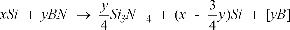
- As described above, when B is solid-solved in Si to decompose BN, the function of the sliding layer is lost, the molten Si and the Si fibers are in direct contact with each other. As a result, the matrix and the fibers are separated from each other in growing of cracks, so that breakdown energy decreases.
- The present inventor obtained the following knowledge. That is, when a molten Si impregnated into a preform reacts with another B material in advance before the molten Si reaches a BN coat layer on the surface of SiC fibers in reaction sintering to form an Si-B solid solution so as to set the molten Si in an inactive state in the BN coat layer in advance, the molten Si does not reacts with B in the BN coating. In this manner, the BN coating can be protected.
- A method of manufacturing a ceramic matrix composite according to the present invention has been made on the basis of the above knowledge. According to this method, a large number of BN-coated SiC continuous fibers are gathered to form yarns, and the yarns are woven to form a two-dimensional or three-dimensional fabric. A preform is formed by using the yarns and the fabric, and C powder is arranged into the gaps between the fibers of the preform to manufacture a compact. There is provided a method of manufacturing a fiber composite ceramic in which a molten Si is impregnated into the compact, and an SiC matrix is formed between the fibers by reaction sintering, characterized in that a region where a B concentration is high is formed around the SiC fibers before the structure is impregnated with a molten Si, and B in the region is solid-solved in Si during reaction sintering so as to prevent B in the BN-coated SiC fibers from being solid-solved in Si.
- According to the method of the present invention, the molten Si with which the structure is impregnated advances in the compact while silicificating C in the matrix. Since the molten Si further advances while solid-solving B in the molten Si in a high B-concentration region around the SiC fibers, when the molten Si reaches the BN coating on the surface of the SiC fibers, a large amount of B has been solid-solved in the molten Si. According to this effect, corrosion of the BN coating, i.e., the degree of solid solution of B, is decreased. For this reason, the BN coating on the SiC fiber surface is held relatively sound. As a result, sliding occurs between the matrix and the continuous fibers during growing of cracks, and resistance to growing of cracks after initial breakdown is improved.
- In the present invention, as a material constituting the region having a high B-concentration, at least one of boron nitride (BN), boron carbide (B4C), and boron oxide (B2O3) is applied. As a matter of course, a material obtained by mixing these compounds with each other may be used.
- When BN is applied, an Si-B solid solution and SiN are formed by a reaction between BN and molten Si. When B4C is used, SiC is formed in the same manner as described above; when B2O3 is used, SiO2 is formed.
- According to the present invention, an aggregate such as SiC or Si3N4 other than a B compound or a matrix formation component such as C is effectively added.
- According to the manufacturing method of the present invention, the B content of the material constituting the region having a high B-concentration is desirably set to be a content having an upper limit as a saturation amount of solid solution in a molten Si impregnated into a preform during reaction sintering. This is because, when the B concentration in a material which has been filled exceeds a saturation amount of solid solution in the molten Si, B is present as a simple substance or a compound, manufacturing cost increases in vain, and the strength of the material is also degraded.
- In the manufacturing method of the present invention, one of the step of adhering a material constituting the region having a high B-concentration to the surface of the SiC fibers of the preform as a powder or an organic compound of B and the step of inserting the material into the gap portion between the fibers for forming the matrix together with C powder for reaction sintering can be selected.
- In the fiber composite ceramic manufactured as described above which is obtained in such a manner that BN-coated SiC fibers coated with a sliding layer consisting of BN are combined with an SiC matrix as yarns or a fabric, the SiC matrix is formed by reaction sintering using a molten Si and C powder, and an Si-B alloy in which B is solid -solved under saturation amount in Si is formed around the BN-coated SiC fiber.
- In the fiber composite ceramic manufactured with the above arrangement, the thickness of the BN coating need not be especially increased, a sufficient sliding effect in growing of cracks can be obtained, and breakdown energy can be increased.
- In order to achieve another object of the present invention, the present inventor formed various types of coating layers on fibers used in a ceramic matrix reinforced composite to examine influences of the coating layers on the ceramic matrix composite . As a result, the present inventor obtained the following knowledge. That is, when a coat layer for performing sliding was formed on the surface of the fibers, and a metal compound layer, especially, an oxide layer was formed as a barrier layer on the outside of the coat layer to suppress the coat layer and the matrix layer from reacting with each other, a composite material having high toughness against breakdown could be obtained.
- According to still another aspect of the present invention, there is provided a ceramic matrix composite in which ceramic fibers are combined with a ceramic matrix formed by reaction sintering and containing SiC as a main component, a sliding coat layer for decreasing a bonding force between the fibers and the matrix and a barrier layer for coating the outside of the sliding coat layer to suppress a reaction with Si are present on the surface of the fibers as a dual coating, characterized in that the sliding coat layer substantially consists of C or BN, and the barrier layer substantially consists of a compound of one element selected from the group consisting of Ta, Nb, Ti, Zr, and Hf.
- In this ceramic matrix composite, a compound constituting the barrier layer is preferably an oxide consisting of Ta2O3, Nb2O5, TiO2, ZrO2, or HfO2.
- The sliding coat layer formed on the surface of the ceramic fibers is formed to prevent the matrix and the ceramic fibers from being strongly coupled with each other when the sliding coat layer consists of a composite material and to make it possible to perform sliding during bridging or pullout. As a material constituting the sliding coat layer, carbon (C), boron nitride (BN), or the like which gives a sliding function to a portion between the matrix and the fibers, is not affected by a sintering temperature, and is thermally stable is used.
- As the barrier layer for suppressing a reaction, a compound of one element selected from Ta, Nb, Ti, Zr, and Hf is effectively used. Of these compounds, Ta2O5, Nb2O5, TiO2, ZrO2, or HfO2 is especially effective.
- As a method of forming the sliding coat layer and the barrier layer, a general-purpose CVD (chemical vapor deposition) method for transferring a metal component together with a carrier gas such as a nitrogen gas, a hydrogen gas, or an argon gas to decompose and precipitate the metal component on the surface of ceramic fibers heated to a predetermined reaction temperature or more can be employed. The metal component may also be formed by a vacuum deposition method for covering the metal component on the fiber surface or a PVD (physical vapor deposition) method such as a sputtering method or an ion plating method. In addition, a method of forming an organic metal chemical or the like constituting the above material after heat treatment by dipping can be employed.
- When ceramic fibers are woven into a predetermined shape to form a stereoscopic fabric, and a sliding coat layer and a barrier layer are formed on the surface of the fabric, the above method can cope with a complex shape.
- In this case, the ceramic fibers constituting fibers for a composite material is a reinforcing member for improving the toughness of a matrix used when the composite material is formed. For example, silicon-carbide-base fibers (SiC, SiC/C, Si-C-O, and Si-Ti-C-O), silicon-nitride-basefibers (Si3N4 and Si3N4/C), alumina fibers (Al2O3), zirconia (ZrO2), or the like are available. Sixty-five % or less by volume of the fibers are preferably added to a ceramic material powder constituting the matrix of the composite material. When the fiber content exceeds 65% by volume, it is difficult to uniformly arrange the matrix around the fiber, and the strength characteristics of the composite material are abruptly degraded. The fiber content is preferably set within the range of 10 to 60% by volume.
- The diameter and length of each ceramic fiber considerably influences the strength characteristics of the composite material. Continuous fiber, short fiber, or the like having a diameter of 3 to 200 µm can be used. When ceramic fibers each having a diameter of less than 3 µm are used, the reinforcing effect of the matrix base is less; when thick fibers each having a diameter of larger than 200 µm are used, cracks are formed due to the difference between the thermal expansions of the fibers and the matrix, or correspondence to a product shape is degraded.
- When the length of each fiber is smaller than 100 µm, cracks are less suppressed from being grown, and the effect of improvement on toughness is also degraded.
- The ceramic matrix composite reinforced by the fibers prepared as described above is manufactured by the following steps, for example. More specifically, ceramic material powder or the like is dispersed in a solvent to prepare slurry, and a preform molded by fibers is impregnated with the slurry by using a casting method (including an atmospheric pressure molding method, a pressure molding method, and a reduced-pressure molding method) or the like to prepare a compact having a predetermined shape. When near net shape which is similar to a final product shape.
- The resultant compact is sintered in an atmosphere of an inert gas such as a nitrogen gas or an argon gas or in a vacuum state by a reaction sintering method at a temperature falling within the range of 1,400 to 2,000°C for about 1 to 10 hours to obtain a composite sintered body.
- More specifically, the fabric is impregnated with a mixture of SiC fine powder and C by a slip cast method to form a compact, and the compact is impregnated with molten Si at a temperature 1,400 to 2,000°C to be sintered. The impregnated Si is caused to react with C in the compact, and a cavity portion is buried with secondarily generated SiC to manufacture a dense fiber reinforced composite material.
- According to the ceramic matrix composite manufactured by the above method, a sliding coat layer for decreasing the bonding force between the fibers and the matrix to perform sliding is present on the surface of the fiber, and a barrier layer for suppressing the reaction between the coat layer and the matrix layer is present on the coat layer. For this reason, the matrix and the fibers can be prevented from being integrated with each other.
- Therefore, the matrix and the ceramic fibers are coupled with each other by appropriate interfacial bonding force. A sliding function between the matrix and the ceramic fibers exhibits, and the breakdown energy of the composite material increases. The sliding function partially exhibits, and a fiber reinforced composite material which is excellent in breakdown toughness value and mechanical strength can be obtained.
- When a barrier layer consisting of an oxide of Ta or the like is to be formed by using an organic-metal-base processing solution, the barrier layer can be formed by dipping or the like. For this reason, the operation for forming the barrier can be easily performed, and mass-production properties can also be effectively improved.
- FIG. 1 is a view showing a section of a preform serving as an incomplete compact of a sample manufactured in
Embodiment 10 of the present invention. - FIG. 2 is a view showing a final section of a sample manufactured in
Embodiment 10 of the present invention. - FIG. 3 is a graph showing a silicon (Si) - boron (B) state.
- An embodiment of the present invention will be described below with reference to the accompanying drawings.
- According to this example, as composite fiber, SiC ceramic fibers , i.e., tradename: Hinicaron (filament needle available from Nippon Carbon Co., Ltd. (diameter: 14 µm) were applied. Five hundred fibers obtained as described above were gathered to form a yarn (500 F/Y), and BN was coated on the surface of the fibers by a CVD method, thereby forming a sliding layer. SiC was coated on the outside of the sliding layer by a CVD method, thereby forming a barrier layer for suppressing the sliding layer from being eluted in molten Si during reaction sintering.
- Thereafter, the yarns which were dual-coated by the above method were woven to form a plain weave cloth, and a plurality of clothes were stacked to form a preform. This preform was set in a mold consisting a porous resin. In this case, the volume percentage of the fiber was set to be 27%.
- The preform set in the mold was impregnated with a ceramic material slurry by a pressure. This ceramic material slurry contained SiC powder having a central grain size of 1 to 3 µm (70 wt%) and carbon black (30 wt%) as a solid component. The ceramic material slurry was prepared by mixing the solid component (50 wt%), diluted water (47 wt%), and an interfacial active agent (3 wt%).
- After the above preform was molded and dried, the preform was brought into contact with B (5 wt%) and molten Si (purity: 99.9 wt%) (B 95 wt%) and heated to 1,430° C for 5 hours in a vacuum state to be impregnated by molten Si. In this manner , reaction sintered SiC was synthesized in the matrix, thereby obtaining a ceramic matrix composite.
- More specifically, in this example, the carbon black served as a C source of SiC generated by reaction sintering between the carbon black and molten Si, and B served as a reactive eluted component with respect to the molten Si. Since the reactive eluted component was present in the molten Si in advance, the BN layer serving as a sliding coat layer could be suppressed from being eluted in the molten Si.
- The density of the obtained composite material was 2.99 g/cm3, as shown in Table 1. When the three-point bending strength of a cut sample piece was measured at room temperature, 450 to 510 MPa could be obtained. The composite material exhibited a pseudo stable breakdown behavior inherent in a composite material, i.e., breakdown occurred not to complete rupture at once.
- When the cut surface was observed with an SEM, a matrix was uniformly formed around every mono-filament, and uniform immersion sintering was performed. In addition, pullout of fibers was conspicuously observed, and it was apparently confirmed that the BN layer serving as a sliding coat layer on the fiber surface and the SiC layer serving as a barrier layer were sound.
- In this example, the same SiC fibers as those in Example 1 were used, and a BN layer was coated on the fibers as a sliding coat layer on the fiber surface by a CVD method. As a barrier layer outside the sliding coat layer, a carbon layer (C layer) different from the barrier layer in Example 1 was used. This C layer was formed by a CVD method.
- As the remaining materials, the same materials as in Example 1 were used, and the same steps as in Example 1 were performed to obtain a ceramic matrix composite.
- The density of the obtained composite material was 2.98 g/cm3, as shown in Table 1. When the three-point bending strength of a cut sample piece was measured at room temperature, 420 to 480 MPa could be obtained. The composite material exhibited a pseudo stable breakdown behavior inherent in a composite material, i.e., breakdown occurred not to complete rupture at once.
- When the cut surface was observed with an SEM, a matrix was uniformly formed around every mono-filament, and uniform immersion sintering was performed. In addition, pullout of fibers was conspicuously observed, and it was apparently confirmed that the BN layer serving as a sliding coat layer on the fiber surface and the C layer serving as a barrier layer were effected.
- In this example, the same SiC fibers as those in Example 1 were used, and a BN layer was coated on the fibers as a sliding coat layer on the fiber surface by a CVD method. As a barrier layer outside the sliding coat layer, a molybdenum layer (Mo layer) different from the barrier layer in each of the above examples was used. This Mo layer was formed by a sputtering method.
- The same preformed as that in each of the above examples was formed by using yarns constituted by the above fibers, and the preform was impregnated with the same ceramic material slurry as described above and dried. The preform was heated in contact with an Si-Mo-B alloy, and infiltration and reaction sintering were performed. In this case, the Mo and B components were components for suppressing the coat layer and the barrier layer from being eluted in molten Si.
- The density of the obtained composite material was 3.10 g/cm3, as shown in Table 1. When the three-point bending strength of a cut sample piece was measured at room temperature, 390 to 430 MPa could be obtained. The composite material exhibited a pseudo stable breakdown behavior inherent in a composite material, i.e., breakdown occurred not to complete rupture at once.
- When the cut surface was observed with an SEM, a matrix was uniformly formed around every mono-filament, and uniform immersion sintering was performed. In addition, pullout of fibers was conspicuously observed, and it was apparently confirmed that the BN layer serving as a sliding coat layer on the fiber surface and the Mo layer serving as a barrier layer were effected.
- In this example, the same SiC fibers as those in Example 5 were used, and a BN layer was coated on the fibers as a sliding coat layer on the fiber surface by a CVD method. As a barrier layer outside the sliding coat layer, a molybdenum silicide layer (MoSi2 layer) different from the barrier layer in each of the above examples was used. This MoSi2 layer was formed by a sputtering method.
- The same preformed as that in each of the above examples was formed by using yarns constituted by the above fibers, and the preform was impregnated with the same ceramic material slurry as described above and dried. The preform was heated in contact with an Si-Mo-B alloy, and infiltration and reaction sintering were performed. In this case, the Mo and Si components were components for suppressing the coat layer and the barrier layer from being eluted in molten Si.
- The density of the obtained composite material was 3.11 g/cm3, as shown in Table 1. When the three-point bending strength of a cut sample piece was measured at room temperature, 400 to 440 MPa could be obtained. The composite material exhibited a pseudo stable breakdown behavior inherent in a composite material, i.e., breakdown occurred not to complete rupture at once.
- When the cut surface was observed with an SEM, a matrix was uniformly formed around every mono-filament, and uniform immersion sintering was performed. In addition, pullout of fibers was conspicuously observed, and it was apparently confirmed that the BN layer serving as a sliding coat layer on the fiber surface and the MoSi2 layer serving as a barrier layer were effected.
- In this example, the same SiC fibers as those in Example 1 were used, and a niobium layer (Nb layer) was coated on the fibers as a sliding coat layer on the fiber surface by a sputtering method. As a barrier layer outside the sliding coat layer, a tungsten layer (W layer) different from the barrier layer in each of the above examples was used. This W layer was formed by a CVD method.
- The same preformed as that in each of the above examples was formed by using yarns constituted by the above fibers, and the preform was impregnated with the same ceramic material slurry as described above and dried. The preform was heated in contact with an Si-Nb-W alloy, and infiltration and reaction sintering were performed. In this case, the Nb and W components were components for suppressing the coat layer and the barrier layer from being eluted in molten Si.
- The density of the obtained composite material was 3.12 g/cm3, as shown in Table 1. When the three-point bending strength of a cut sample piece was measured at room temperature, 270 to 320 MPa could be obtained. The composite material exhibited a pseudo stable breakdown behavior inherent in a composite material, i.e., breakdown occurred not to complete rupture at once.
- When the cut surface was observed with an SEM, a matrix was uniformly formed around every mono-filament, and uniform immersion sintering was performed. In addition, pullout of fibers was conspicuously observed, and it was apparently confirmed that the Nb layer serving as a sliding coat layer on the fiber surface and the W layer serving as a barrier layer were effected.
- In this example, the same SiC fibers as those in Example 1 were used, and a niobium-yttrium layer (Nb-Y layer) was coated on the fibers as a sliding coat layer on the fiber surface by a sputtering method. As a barrier layer outside the sliding coat layer, a zirconium-yttrium layer (Zr-Y layer) different from the barrier layer in each of the above examples was used. This Zr-Y layer was formed by a CVD method.
- The same preformed as that in each of the above examples was formed by using yarns constituted by the above fibers, and the preform was impregnated with the same ceramic material slurry as described above and dried. The preform was heated in contact with a Si-Nb-Zr-Y alloy, and infiltration and reaction sintering were performed. In this case, the Nb,Zr and Y components were components for suppressing the coat layer and the barrier layer from being eluted in molten Si.
- The density of the obtained composite material was 3.12 g/cm3, as shown in Table 1. When the three-point bending strength of a cut sample piece was measured at room temperature, 240 to 310 MPa could be obtained. The composite material exhibited a pseudo stable breakdown behavior inherent in a composite material, i.e., breakdown occurred not to complete rupture at once.
- When the cut surface was observed with an SEM, a matrix was uniformly formed around every mono-filament, and uniform immersion sintering was performed. In addition, pullout of fibers was conspicuously observed, and it was apparently confirmed that the Nb-Y layer serving as a sliding coat layer on the fiber surface and the Zr-Y layer serving as a barrier layer were effected.
- In this example, the same SiC fibers as those in Example 1 were used, and a alumina layer (Al2O3 layer) was coated on the fibers as a sliding coat layer on the fiber surface by a sol-gel method. As a barrier layer outside the sliding coat layer, a zirconia layer (ZrO2 layer) different from the barrier layer in each of the above examples was used. This ZrO2 layer was formed by a CVD method.
- The same preformed as that in each of the above examples was formed by using yarns constituted by the above fibers, and the preform was impregnated with the same ceramic material slurry as described above and dried. The preform was heated in contact with an Si-Al-Zr alloy, and infiltration and reaction sintering were performed. In this case, the Al and Zr components were components for suppressing the coat layer and the barrier layer from being eluted in molten Si.
- The density of the obtained composite material was 3.09 g/cm3, as shown in Table 1. When the three-point bending strength of a cut sample piece was measured at room temperature, 920 to 350 MPa could be obtained. The composite material exhibited a pseudo stable breakdown behavior inherent in a composite material, i.e., breakdown occurred not to complete rupture at once.
- When the cut surface was observed with an SEM, a matrix was uniformly formed around every mono-filament, and uniform immersion sintering was performed. In addition, pullout of fibers was conspicuously observed, and it was apparently confirmed that the Al2O3 layer serving as a sliding coat layer on the fiber surface and the ZrO2 layer serving as a barrier layer were effected.
- In this example, the same SiC fibers as those in Example 1 were used, and a aluminium nitride layer (AlN layer) was coated on the fibers as a sliding coat layer on the fiber surface by a CVD method. As a barrier layer outside the sliding coat layer, a titanium nitride layer (TiN layer) different from the barrier layer in each of the above examples was used. This TiN layer was formed by a sol-gel method.
- The same preformed as that in each of the above examples was formed by using yarns constituted by the above fibers, and the preform was impregnated with the same ceramic material slurry as described above and dried. The preform was heated in contact with an Si-Al-Ti alloy, and infiltration and reaction sintering were performed. In this case, the AL and Ti components were components for suppressing the coat layer from being eluted in molten Si.
- The density of the obtained composite material was 3.03 g/cm3, as shown in Table 1. When the three-point bending strength of a cut sample piece was measured at room temperature, 330 to 370 MPa could be obtained. The composite material exhibited a pseudo stable breakdown behavior inherent in a composite material, i.e., breakdown occurred not to complete rupture at once.
- When the cut surface was observed with an SEM, a matrix was uniformly formed around every mono-filament, and uniform immersion sintering was performed. In addition, pullout of fibers was conspicuously observed, and it was apparently confirmed that the AlN layer serving as a sliding coat layer on the fiber surface and the TiN layer serving as a barrier layer were effected.
- In this example, the same SiC fibers as those in Example 1 were used, and a Carbon layer (C layer) was coated on the fibers as a sliding coat layer on the fiber surface by a CVD method. As a barrier layer outside the sliding coat layer, a boron carbide layer (B4C layer) different from the barrier layer in each of the above examples was used. This B4C layer was formed by a CVD method.
- The same preformed as that in each of the above examples was formed by using yarns constituted by the above fibers, and the preform was impregnated with the same ceramic material slurry as described above and dried. The preform was heated in contact with an Si-B alloy, and infiltration and reaction sintering were performed. In this case, the B components were components for suppressing the coat layer from being eluted in molten Si.
- The density of the obtained composite material was 3.00 g/cm3, as shown in Table 1. When the three-point bending strength of a cut sample piece was measured at room temperature, 370 to 400 MPa could be obtained. The composite material exhibited a pseudo stable breakdown behavior inherent in a composite material, i.e., breakdown occurred not to complete rupture at once.
- When the cut surface was observed with an SEM, a matrix was uniformly formed around every mono-filament, and uniform immersion sintering was performed. In addition, pullout of fibers was conspicuously observed, and it was apparently confirmed that the C layer serving as a sliding coat layer on the fiber surface and the B4C layer serving as a barrier layer were effected.
- A preform corresponding to each of Examples 1 to 9 was impregnated with a metal Si (purity: 99.9 wt%) at 1,430° C for 5 hours in a vacuum state, and was subjected to reaction sintering.
- When a bending test was performed to the resultant sample, although break down did not occur at once in the sample, the brittleness of this sample was larger than that of the sample in each of the examples described above.
- When a cut surface was observed with an SEM, the BN coat layer partially reacted with the molten Si, with which the sample was impregnated, to be eliminated, and a portion where the fibers and the matrix were integrated with each other such that the appearance of the fibers was inconspicuous could be detected.
- The same preform as that in Example 1 was formed except that an SiC barrier layer was not formed. The preform was impregnated with the same Si-B alloy (B: 5 wt%) and subjected to reaction sintering to obtain a sample.
- When a bending test was performed to the resultant sample, although breakdown did not occur at once in the sample, the sample was more brittle.
- When a cut surface was observed with an SEM, the BN coat layer partially reacted with the molten Si, with which the sample was impregnated, to be eliminated, and a portion where the fibers and the matrix were integrated with each other such that the appearance of the fibers was inconspicuous could be detected.
-

- In this example, as a B source for forming a high-concentration B region, BN was used. The BN powder and C powder were mixed with each other in water to form a slip. This slip was stored in a predetermined vessel, a yarn consisting of BN-coated SiC fibers was inserted into the slip and subjected to a dipping operation.
- As the SiC fibers, tradename: Hinicaron (filament needle available from Nippon Carbon Co., Ltd. (diameter: 14 µm)) was applied. A BN coating serving as a sliding layer and having a thickness of 0.4 m was formed on the surface of the filament, thereby obtaining the BN-coated SiC fibers.
- Five hundred BN-coated BN-coated SiC fibers obtained as described above were gathered to form a yarn, and the yarn was dipped in the BN and C slip. The dipped BN-coated SiC fibers were dried to adhere the BN powder and C powder to the surface of the fibers. The amount of adhered BN powder was set to be an amount of solid solution of B saturated with respect to Si (will be impregnated later). This will be described later.
- The yarn of the BN-coated SiC fibers to which the BN powder and C powder were adhered was arranged inside a plaster mold. The slip consisting of only C powder was poured into the plaster mold and then dried to fill the C powder in a portion prospectively serving as a matrix in the gap between fibers, thereby obtaining a compact. The compact formed in this example has an almost rectangular parallelopiped (vertical: 40 mm × horizontal: 40m × thickness: 5mm), and the volume percentage of the SiC fibers was set to be 25%.
- FIG. 1 shows the sectional shape of the obtained compact A. As shown in FIG. 1, a
BN coating 2 serving as a sliding layer is formed on the outer peripheral surface ofSiC fibers 1, and apredetermined region 3 which is located around theBN coating 2 and indicated by a broken line is a high B-concentration region obtained by adheringBN powder 4 andC powder 5 to theBN coating 2. In addition,C powder 7 is filled inother regions 6. - A molten Si at 1,450°C was impregnated into the compact A described above to perform reaction sintering between the C powder constituting the compact A and the molten Si, thereby obtaining an SiC fiber composite ceramic sample containing SiC as a matrix.
- FIG. 2 shows the sectional shape of the resultant sample. As shown in FIG. 2, the
BN coating 2 was left on the outer peripheral surface of theSiC fibers 1 in a sound state without being damaged. In theregion 3 shown in FIG. 1 and having a high B concentration, an Si-B solid solution was present. For this reason, when reaction sintering was performed by injecting the molten Si, B in the BN powder in theregion 3 having a high B concentration was solid-solved in the molten Si to generate an Si-B solid solution. When the molten Si reached theBN coating 2 on the surface of theSiC fibers 1, the Si-B solid solution had been generated, the followings were confirmed. That is, B was not discharged from theBN coating 2 on the SiC fiber surface, and the coating was protected. Referring to FIG. 2,reference numeral 8 denotes an SiC matrix portion generated by reaction sintering. - When the samples (Example 10 and Comparative Example 4) were examined with respect to breakdown energy and a rate of residual fiber, as shown in Table 2, breakdown energy was 1.9, and a rate of residual fiber was 90% in Example 10. In contrast to this, in Comparative Example 3, breakdown energy was 1, and a rate of residual fiber was 40%.
- FIG. 3 is a graph showing an Si - B state. As shown in FIG. 5, an amount of B solid-solved in Si depends on a melting temperature. In this example, although the temperature of a molten Si impregnated into a preform for reaction sintering is set to 1,450°C, in this case, a saturation amount of solid solution of B is 5% by weight. When the temperature of the molten Si is 1,390°C, the amount of solid solution of B is 3% by weight; and when the temperature is 1,410°C, the amount is 1% by weight. That is, the amount of solid solution is decreased with a decrease in temperature. For reaction sintering, the molten Si preferably has a high temperature. However, in this case, since a damage rate of fibers increases, an excessive high temperature is not always preferable. Totally, as in this example, the temperature of the molten Si was optimally set to 1,450°C.
- According to the same steps as in Example 10, B4C (Example 11) and B2O3 (Example 12) were applied as B components for forming regions each having a high B concentration to prepare samples of Si fiber composite ceramic.
- When these samples were examined with respect to breakdown energy and a rate of residual fiber, as shown in Table 2, in each of both Examples 11 and 12, the breakdown energy was 1.8, and the rate of residual fiber was 85%.
- In Example 13, unlike the above examples, a yarn of BN-coated SiC fibers was arranged in a plaster mold without adhering B compound powder to the surface of the BN-coated SiC fiber, a slip of C powder and BN powder whose amount was smaller than an amount of solid solution saturated with respect to Si was poured into the plaster mold, so that the BN powder was present in the gap portion between fibers.
- A molten Si was impregnated into a dried preform to perform reaction sintering, thereby preparing a sample.
- With respect to this sample, as shown in Table 2, breakdown energy was 1.7, and a rate of residual fiber was 80%.
- BN-coated SiC fibers were arranged in a plaster mold, and a slip in which only C powder was solved was poured into the plaster mold. The resultant structure was dried to obtain a preform.
- A molten Si was impregnated into the preform to perform reaction sintering, thereby preparing a sample.
- As a result, as shown in Table 2, breakdown energy was 1 and a rate of residual fabric was 40%. Therefore, the strength of this sample was lower than those of the samples in the above examples.
- In this comparative example, the same material as that in Example 10, and a sample was prepared by the same steps as those in Example 1. However, in this case, a BN powder content for forming a region having a high B concentration was set to be larger than an amount of solid solution saturated with respect to molten Si.
- With respect to the sample obtained as the result, breakdown energy was 1.2, and a rate of residual fiber was 85%. More specifically, breakdown strength is degraded because BN is left in the matrix. As a result, breakdown energy may be degraded.
- With respect to Examples 10 to 13 and Comparative Examples 3 and 4, examination results are shown in Table 2. Breakdown energy is measured by a three-point bending test, the breakdown energy in Comparative Example 3 is standardized as 1. A rate of residual f0iber is obtained by measuring a rate of residual sound BN-coated SiC fibers by observing the fine structure of a cut surface.
-

- According to this example, as in Examples 1 and 10, as composite fiber, an SiC ceramic fiber, i.e., tradename: Hinicaron (filament needle available from Nippon Carbon Co., Ltd. (diameter: 14 µm)) was used as a fiber element. A BN layer having a thickness of 0.4 µm was coated on the surface of the fibers by a CVD method, thereby forming a sliding coat layer.
- These fibers were dipped in a Ta-base organic metal compound solution (organic-metal-base processing solution (tradename: (Ta-700) available from Nippon Soda Co., Ltd. and used as a functional thin film material) and sintered in the air to form a Ta2O5 barrier layer having a thickness of 0.1 µm.
- The fibers were woven to form a plain weave cloth, and a plurality of clothes were stacked. The stacked structure was set in a mold consisting a porous resin (Vf = 27%), and was impregnated with a matrix material slurry by a pressure.
- This ceramic material slurry contained SiC powder having a central grain size of 1 to 3 µm (70 wt%) and carbon black (30 wt%) as a solid component. The ceramic material slurry was prepared by mixing the solid component (50 wt%), diluted water (47 wt%), and an interfacial active agent (3 wt%).
- The resultant structure was molded, dried, and heated at 1,430°C in a vacuum state in contact with melted metal Si (purity: 99.9 wt%) for 5 hours to synthesize reactive sintered SiC on the matrix, thereby obtaining a composite material.
- The density of the obtained composite material was 2.9 g/cm3. When the three-point bending strength of a cut sample piece was measured at room temperature, 420 to 460 MPa could be obtained. The composite material exhibited a pseudo stable breakdown behavior inherent in a composite material, i.e., breakdown occurred not to complete rupture at once. When the cut surface was observed with an SEM, a matrix was uniformly formed around every mono-filament, and uniform immersion sintering was performed. In addition, pullout of fibers was conspicuously observed, and it was apparently confirmed that the BN layer serving as a sliding coat layer was sound.
- In this example, the same SiC-base ceramic fibers as in Example 14 were used as a fiber material. A BN layer having a thickness of 0.4 µm was coated on the surface of the fibers by a CVD method, thereby forming a sliding coat layer.
- These fibers were dipped in an Nb-base organic metal compound solution and sintered in the air to form a Nb2O5 barrier layer having a thickness of 0.2 µm. The fibers were woven to form a plain weave cloth, and a plurality of clothes were stacked. The stacked structure was set in a mold consisting a porous resin (Vf = 27%), and was impregnated with a matrix material slurry by a pressure. The ceramic material slurry was the same as in Example 14.
- The resultant structure was molded, dried, and heated at 1,430°C in a vacuum state in contact with melted metal Si (purity: 99.9 wt%) for 5 hours to synthesize reactive sintered SiC on the matrix, thereby obtaining a composite material.
- The density of the obtained composite material was 2.9 g/cm3. When the three-point bending strength of a cut sample piece was measured at room temperature, 400 to 450 MPa could be obtained. The composite material exhibited a pseudo stable breakdown behavior inherent in a composite material, i.e., breakdown occurred not to complete rupture at once. When the cut surface was observed with an SEM, a matrix was uniformly formed around every mono-filament, and uniform immersion sintering was performed. In addition, pullout of fibers was conspicuously observed, and it was apparently confirmed that the BN layer serving as a sliding coat layer was sound.
- In this example, the same SiC-base ceramic fibers as in Example 14 were used as a fiber material. A BN layer having a thickness of 0.4 µm was coated on the surface of the fibers by a CVD method, thereby forming a sliding coat layer.
- These fibers were dipped in a Ti-base organic metal compound solution and sintered in the air to form a TiO2 barrier layer having a thickness of 0.2 µm. The fibers were woven to form a plain weave cloth, and a plurality of clothes were stacked. The stacked structure was set in a mold consisting a porous resin (Vf = 27%), and was impregnated with a matrix material slurry by a pressure. The ceramic material slurry was the same as in Example 14.
- The resultant structure was molded, dried, and heated at 1,430°C in a vacuum state in contact with melted metal Si (purity: 99.9 wt%) for 5 hours to synthesize reactive sintered SiC on the matrix, thereby obtaining a composite material.
- The density of the obtained composite material was 2.9 g/cm3. When the three-point bending strength of a cut sample piece was measured at room temperature, 330 to 380 MPa could be obtained. The composite material exhibited a pseudo stable breakdown behavior inherent in a composite material, i.e., breakdown occurred not to complete rupture at once. When the cut surface was observed with an SEM, a matrix was uniformly formed around every mono-filament, and uniform immersion sintering was performed. In addition, pullout of fibers was conspicuously observed, and it was apparently confirmed that the BN layer serving as a sliding coat layer was sound.
- In this example, the same SiC-base ceramic fibers as in Example 14 were used as a fiber material. A BN layer having a thickness of 0.4 µm was coated on the surface of the fibers by a CVD method, thereby forming a sliding coat layer.
- These fibers were dipped in a Zr-base organic metal compound solution and sintered in the air to form a ZrO2 barrier layer having a thickness of 0.2 µm. The fibers were woven to form a plain weave cloth, and a plurality of clothes were stacked. The stacked structure was set in a mold consisting a porous resin (Vf = 27%), and was impregnated with a matrix material slurry by a pressure. The ceramic material slurry was the same as in Example 9.
- The resultant structure was molded, dried, and heated at 1,430°C in a vacuum state in contact with melted metal Si (purity: 99.9 wt%) for 5 hours to synthesize reactive sintered SiC on the matrix, thereby obtaining a composite material.
- The density of the obtained composite material was 2.9 g/cm3. When the three-point bending strength of a cut sample piece was measured at room temperature, 320 to 360 MPa could be obtained. The composite material exhibited a pseudo stable breakdown behavior inherent in a composite material, i.e., breakdown occurred not to complete rupture at once. When the cut surface was observed with an SEM, a matrix was uniformly formed around every mono-filament, and uniform immersion sintering was performed. In addition, pullout of fibers was conspicuously observed, and it was apparently confirmed that the BN layer serving as a sliding coat layer was sound.
- In this example, the same SiC-base ceramic fibers as in Example 14 were used as a fiber material. A BN layer having a thickness of 0.4 µm was coated on the surface of the fibers by a CVD method, thereby forming a sliding coat layer.
- These fibers were dipped in a Hf-base organic metal compound solution and sintered in the air to form a HfO2 barrier layer having a thickness of 0.2 µm. The fibers were woven to form a plain weave cloth, and a plurality of clothes were stacked. The stacked structure was set in a mold consisting a porous resin (Vf = 27%), and was impregnated with a matrix material slurry by a pressure. The ceramic material slurry was the same as in Example 14.
- The resultant structure was molded, dried, and heated at 1,430°C in a vacuum state in contact with melted metal Si (purity: 99.9 wt%) for 5 hours to synthesize reactive sintered SiC on the matrix, thereby obtaining a composite material.
- The density of the obtained composite material was 2.9 g/cm3. When the three-point bending strength of a cut sample piece was measured at room temperature, 330 to 390 MPa could be obtained. The composite material exhibited a pseudo stable breakdown behavior inherent in a composite material, i.e., breakdown occurred not to complete rupture at once. When the cut surface was observed with an SEM, a matrix was uniformly formed around every mono-filament, and uniform immersion sintering was performed. In addition, pullout of fibers was conspicuously observed, and it was apparently confirmed that the BN layer serving as a sliding coat layer was sound.
- When a barrier layer consisting of a compound of at least one element selected from Ta, Nb, Ti, Zr, or Hf except for the oxides described above was formed on fibers in the same manner as described above, the same effect as in Examples 14 to 18 could be obtained.
- A composite material was formed in the same manner as in Example 14 except that the same fibers as in Example 9 were coated with only a single BN layer without being coated with a barrier layer.
- As a result, when a three-point bending test was performed to the composite material, although breakdown did not occur at once in the composite material, the composite material exhibited a breakdown behavior which is more brittle than that of a composite material on which a protective reaction barrier was coated. When the cut surface of a test piece after the test was observed, a BN coat layer partially reacted with molten Si to be eliminated, and a portion where the fibers and the matrix were integrated with each other could be detected.
- A composite material was formed in the same manner as in Example 14 except that the same fibers as in Example 9 were coated with only a single carbon layer without being coated with a barrier layer.
- As a result, when a three-point bending test was performed to the composite material, although breakdown did not occur at once in the composite material, the composite material exhibited a breakdown behavior which is more brittle than that of a composite material on which a protective reaction barrier was coated. When the cut surface of a test piece after the test was observed, a carbon coat layer partially reacted with molten Si to be eliminated, and a portion where the fibers and the matrix were integrated with each other could be detected.
Claims (16)
- A ceramic matrix composite in which ceramic fibers are combined with a ceramic matrix formed by reaction sintering and containing SiC as a main component, and a sliding coat layer for decreasing bonding force between said fibers and said matrix to perform sliding is present on a surface of said fiber, characterized in a component which prevents a reaction between molten Si and said sliding coat layer during the reaction sintering is present in said matrix together with Si .
- A ceramic matrix composite in which ceramic fibers are combined with a ceramic matrix formed by reaction sintering and containing SiC as a main component, and a sliding coat layer for decreasing bonding force between said fibers and said matrix to perform sliding and a barrier layer for coating an outside of said sliding coat layer to suppress a reaction between said sliding coat layer and Si are present on a surface of said fiber, characterized in a component which prevents a reaction between molten Si and said sliding coat layer during the reaction sintering is present in said matrix together with Si .
- A ceramic matrix composite according to claim 1 or 2, characterized in that said sliding coat layer consists of at least one selected from the group consisting of a pure metal, an alloy, a metal oxide, a metal nitride, a metal carbide, a metal boride, and these compounds, and a component which is present in said matrix together with Si consists of a positive metal element, carbon, boron, or a material consisting of at least one of the elements.
- A ceramic matrix composite according to claim 1 or 2, characterized in that the component which is present in said matrix together with Si is the same as the component constituting said sliding coat layer.
- A ceramic matrix composite according to claim 3, characterized in that a metal boride constituting said sliding coat layer is BN, and the content which is present in said matrix together with Si is a B alloy.
- A ceramic matrix composite according to claim 2, characterized in that said barrier layer constituting a dual coating on the fiber surface is at least one selected from the group consisting of SiC, C, Mo, and MoSi2.
- A ceramic matrix composite according to claim 1 or 2, characterized in that the content contained in said matrix together with Si is at least one selected from the group consisting of Ti, V, Cr, Zr, Nb, Mo, Hf, Ta, and W.
- A method of manufacturing a ceramic matrix composite in which a preform constituted by ceramic fibers is impregnated with molten Si to perform reaction sintering between C powder, thereby combining said fibers with a matrix containing SiC as a main component, characterized in that a sliding coat layer for decreasing bonding force between said fibers and said matrix to perform sliding is formed on a surface of said fibers , and a discomposing component which is prevented a reaction between the molten Si and said sliding coat layer during reaction sintering is added to Si to suppress said sliding coat layer react with the molten Si.
- A method of manufacturing a ceramic matrix composite in which a preform constituted by ceramic fibers is impregnated with molten Si to perform reaction sintering between C powder, thereby combining said fibers with a matrix containing SiC as a main component, characterized in that a sliding coat layer for decreasing bonding force between said fibers and said matrix to perform sliding and a barrier layer covering said sliding coat layer to suppress a reaction between said sliding coat layer and Si are formed on a surface of said fibers , and a discomposing component which is prevented a reaction between the molten Si and said sliding coat layer during reaction sintering is added to Si to suppress said sliding coat layer and said barrier layer react with the molten Si.
- A ceramic matrix composite in which SiC continuous fibers coated with a sliding coat layer consisting of BN are combined with a matrix containing SiC as a main component, said SiC matrix being formed by reaction sintering using a molten Si and C powder, characterized in that an Si-B alloy in which B is solid-solved under in Si is formed around said BN-coated SiC continuous fiber.
- A method of manufacturing a ceramic matrix composite in which a large number of BN-coated SiC continuous fibers are gathered to form yarns, or yarns are woven to form a two-dimensional or three-dimensional fabric, and a preform is formed by said yarns or said fabric, carbon powder is arranged between fibers of said preform to form a compact, a molten Si is impregnated into said compact to form an SiC matrix between fibers, characterized in that a region having a high B concentration is formed around said SiC fibers before said preform is impregnated with the molten Si, and B in the region is solid-solved in Si during reaction sintering to suppress B in said BN-coated SiC continuous fibers from being solid-solved in Si.
- A method of manufacturing a ceramic matrix composite according to claim 11, characterized in that, as a material constituting the region having a high B concentration, at least one selected from the group consisting of BN, B4C, and B2O3 is applied.
- A method of manufacturing a ceramic matrix composite according to claim 11, characterized in that a B content of a material constituting the region having a high B concentration is set to be a content having, as an upper limit, a saturation amount of solid solution in the molten Si impregnated into said preform during the reaction sintering.
- A method of manufacturing a ceramic matrix composite according to claim 11, characterized in that a material constituting the region having a high B concentration is adhered to a surface of said SiC continuous fibers in a powder state, or arranged between fibers together with C powder .
- A ceramic matrix composite in which ceramic fibers are combined with a ceramic matrix formed by reaction sintering and containing SiC as a main component, and a sliding coat layer for decreasing bonding force between said fibers and said matrix to perform sliding and a barrier layer for coating an outside of said sliding coat layer to suppress a reaction between said sliding coat layer and Si are present on a surface of said fibers as a dual coating, characterized in that said sliding coat layer substantially consists of C or BN, and said barrier layer consists of a compound of one element selected from the group consisting of Ta, Nb, Ti, Zr, and Hf.
- A ceramic matrix composite according to claim 15, characterized in that a compound constituting said barrier layer is an oxide consisting of Ta2O3, Nb2O5, TiO2, ZrO2, or HfO2.
Applications Claiming Priority (9)
| Application Number | Priority Date | Filing Date | Title |
|---|---|---|---|
| JP07779596A JP3673011B2 (en) | 1996-03-29 | 1996-03-29 | Ceramic-based fiber composite material and manufacturing method thereof |
| JP8077796A JPH09268063A (en) | 1996-03-29 | 1996-03-29 | Ceramics-based fiber composite material |
| JP77796/96 | 1996-03-29 | ||
| JP7779696 | 1996-03-29 | ||
| JP77795/96 | 1996-03-29 | ||
| JP7779596 | 1996-03-29 | ||
| JP8103653A JPH09268065A (en) | 1996-03-30 | 1996-03-30 | Continuous filament composite ceramics and their production |
| JP103653/96 | 1996-03-30 | ||
| JP10365396 | 1996-03-30 |
Publications (3)
| Publication Number | Publication Date |
|---|---|
| EP0798281A2 true EP0798281A2 (en) | 1997-10-01 |
| EP0798281A3 EP0798281A3 (en) | 1998-01-28 |
| EP0798281B1 EP0798281B1 (en) | 2000-08-02 |
Family
ID=27302521
Family Applications (1)
| Application Number | Title | Priority Date | Filing Date |
|---|---|---|---|
| EP97105371A Expired - Lifetime EP0798281B1 (en) | 1996-03-29 | 1997-04-01 | Ceramic matrix composite and method of manufacturing the same |
Country Status (3)
| Country | Link |
|---|---|
| US (1) | US5955391A (en) |
| EP (1) | EP0798281B1 (en) |
| DE (1) | DE69702677T2 (en) |
Cited By (11)
| Publication number | Priority date | Publication date | Assignee | Title |
|---|---|---|---|---|
| EP1059274A1 (en) * | 1999-06-07 | 2000-12-13 | General Electric Company | Silicon-doped boron nitride coated fibers in silicon melt infiltrated composites |
| WO2000062007A3 (en) * | 1999-03-31 | 2001-02-08 | Textron Systems Corp | Composite armor and fabrication method |
| WO2003084872A2 (en) * | 2000-11-21 | 2003-10-16 | M Cubed Technologies, Inc. | Toughness enhanced silicon-containing composite bodies, and methods for making same |
| US6995103B2 (en) | 2000-11-21 | 2006-02-07 | M Cubed Technologies, Inc. | Toughness enhanced silicon-containing composite bodies, and methods for making same |
| US7223465B2 (en) | 2004-12-29 | 2007-05-29 | General Electric Company | SiC/SiC composites incorporating uncoated fibers to improve interlaminar strength |
| AU2002367779B2 (en) * | 2000-11-21 | 2008-11-13 | M Cubed Technologies, Inc. | Toughness enhanced silicon-containing composite bodies, and methods for making same |
| RU2511415C1 (en) * | 2012-09-17 | 2014-04-10 | Максим Вячеславович Бушуев | Ceramic material based on silicon carbide and nitride and method of manufacturing products from it |
| EP3514125A1 (en) * | 2018-01-17 | 2019-07-24 | Siemens Aktiengesellschaft | Fibre composite material with ceramic fibres, component, gas turbine and method |
| US10464849B2 (en) | 2015-12-08 | 2019-11-05 | Edward J. A. Pope | Fast-densified ceramic matrix composite and fabrication method |
| US10822998B2 (en) | 2013-03-05 | 2020-11-03 | General Electric Company | High temperature tolerant ceramic matrix composites and environmental barrier coatings |
| EP3231782B1 (en) * | 2014-12-12 | 2021-01-13 | Kyoto University | Silicon carbide fiber reinforced silicon carbide composite material and methods of making it |
Families Citing this family (27)
| Publication number | Priority date | Publication date | Assignee | Title |
|---|---|---|---|---|
| DE19711829C1 (en) * | 1997-03-21 | 1998-09-03 | Daimler Benz Ag | Process for the production of a fiber-reinforced composite ceramic |
| WO2000007959A1 (en) * | 1998-08-07 | 2000-02-17 | Bridgestone Corporation | Silicon carbide sinter and process for producing the same |
| US6517341B1 (en) * | 1999-02-26 | 2003-02-11 | General Electric Company | Method to prevent recession loss of silica and silicon-containing materials in combustion gas environments |
| US7104177B1 (en) | 2000-01-11 | 2006-09-12 | Aghajanian Michael K | Ceramic-rich composite armor, and methods for making same |
| EP1399396A2 (en) * | 2000-11-21 | 2004-03-24 | M Cubed Technologies Inc. | Boron carbide composite bodies, and methods for making same |
| US6630029B2 (en) * | 2000-12-04 | 2003-10-07 | General Electric Company | Fiber coating method and reactor |
| DE10252753B3 (en) * | 2002-10-02 | 2004-02-19 | Verschleiß-Technik Dr.-Ing. Hans Wahl GmbH & Co. | Molded body used as wear protection comprises a sintered body made from sintered metallic matrix particles close to a first outer surface and made from a sintered mixture of matrix |
| DE102004001644A1 (en) * | 2004-01-12 | 2005-08-04 | Mtu Aero Engines Gmbh | Composite semifinished product and method for producing a composite semifinished product |
| US7597838B2 (en) * | 2004-12-30 | 2009-10-06 | General Electric Company | Functionally gradient SiC/SiC ceramic matrix composites with tailored properties for turbine engine applications |
| JP5916088B2 (en) * | 2012-01-18 | 2016-05-11 | 国立研究開発法人宇宙航空研究開発機構 | Method for producing ceramic fiber reinforced composite material and ceramic fiber reinforced composite material |
| US10047015B2 (en) | 2012-01-20 | 2018-08-14 | Free Form Fibers, Llc | High strength ceramic fibers and methods of fabrication |
| DE102012201648A1 (en) | 2012-02-03 | 2013-08-08 | Sgl Carbon Se | Fiber reinforced silicon carbide composites |
| US9446989B2 (en) | 2012-12-28 | 2016-09-20 | United Technologies Corporation | Carbon fiber-reinforced article and method therefor |
| US10233126B2 (en) * | 2015-08-12 | 2019-03-19 | Rolls-Royce Corporation | Forming a ceramic matrix composite having a silicide layer |
| US10995040B2 (en) * | 2016-03-14 | 2021-05-04 | Rolls-Royce High Temperature Composites, Inc. | Ceramic matrix composite components having a deltoid region and methods for fabricating the same |
| EP3511308B1 (en) * | 2016-09-06 | 2021-03-03 | IHI Corporation | Production method of ceramic matrix composite |
| CA3044401C (en) | 2016-11-29 | 2023-09-19 | Free Form Fibers, Llc | Fiber with elemental additive(s) and method of making |
| JP6862280B2 (en) | 2017-05-25 | 2021-04-21 | イビデン株式会社 | Method for manufacturing SiC / SiC composite material |
| US10676391B2 (en) | 2017-06-26 | 2020-06-09 | Free Form Fibers, Llc | High temperature glass-ceramic matrix with embedded reinforcement fibers |
| EP3645279A4 (en) | 2017-06-27 | 2021-05-26 | Free Form Fibers, LLC | Functional high-performance fiber structure |
| FR3087194B1 (en) * | 2018-10-12 | 2021-02-26 | Safran Aircraft Engines | PROCESS FOR MANUFACTURING A PART IN COMPOSITE MATERIAL WITH CHECK OF CONFORMITY |
| DE102019213351A1 (en) * | 2019-09-03 | 2021-03-04 | Fraunhofer-Gesellschaft zur Förderung der angewandten Forschung e.V. | Process for the production of fiber-reinforced composite materials with stabilized fibers, fiber coatings and / or fiber bundle coatings |
| US11761085B2 (en) | 2020-08-31 | 2023-09-19 | Free Form Fibers, Llc | Composite tape with LCVD-formed additive material in constituent layer(s) |
| CN112430111A (en) * | 2020-11-19 | 2021-03-02 | 航天特种材料及工艺技术研究所 | Self-healing modified SiC/SiC composite material and preparation method thereof |
| US20220315493A1 (en) * | 2021-04-03 | 2022-10-06 | Palo Alto Research Center Incorporated | Method and composition of scalable, infiltration free ceramic matrix composite |
| CN113652088B (en) * | 2021-08-13 | 2022-09-23 | 航天特种材料及工艺技术研究所 | Preparation method of flexible insulating corrosion-resistant material |
| CN116986915B (en) * | 2023-09-26 | 2023-12-05 | 中国航发北京航空材料研究院 | Continuous preparation device and preparation method of ceramic matrix composite water-oxygen resistant interface layer |
Citations (2)
| Publication number | Priority date | Publication date | Assignee | Title |
|---|---|---|---|---|
| GB2250516A (en) * | 1988-07-08 | 1992-06-10 | Gen Electric | Fiber-containing composite |
| US5330854A (en) * | 1987-09-24 | 1994-07-19 | General Electric Company | Filament-containing composite |
Family Cites Families (9)
| Publication number | Priority date | Publication date | Assignee | Title |
|---|---|---|---|---|
| US4642271A (en) * | 1985-02-11 | 1987-02-10 | The United States Of America As Represented By The Secretary Of The Navy | BN coating of ceramic fibers for ceramic fiber composites |
| US5290737A (en) * | 1985-07-22 | 1994-03-01 | Westinghouse Electric Corp. | Fiber-reinforced metal or ceramic matrices |
| US4944904A (en) * | 1987-06-25 | 1990-07-31 | General Electric Company | Method of obtaining a fiber-containing composite |
| US5021367A (en) * | 1987-06-25 | 1991-06-04 | General Electric Company | Fiber-containing composite |
| US5387299A (en) * | 1988-12-27 | 1995-02-07 | General Electric Company | Ceramic composite containing coated fibrous material |
| US5316851A (en) * | 1991-06-12 | 1994-05-31 | General Electric Company | Silicon carbide composite with metal boride coated fiber reinforcement |
| EP0519641A1 (en) * | 1991-06-17 | 1992-12-23 | General Electric Company | Silicon carbide composite with coated fiber reinforcement and method of forming |
| EP0519644B1 (en) * | 1991-06-17 | 1996-12-11 | General Electric Company | Silicon carbide composite with metal nitride coated fiber reinforcement |
| US5296311A (en) * | 1992-03-17 | 1994-03-22 | The Carborundum Company | Silicon carbide reinforced reaction bonded silicon carbide composite |
-
1997
- 1997-03-28 US US08/827,248 patent/US5955391A/en not_active Expired - Fee Related
- 1997-04-01 EP EP97105371A patent/EP0798281B1/en not_active Expired - Lifetime
- 1997-04-01 DE DE69702677T patent/DE69702677T2/en not_active Expired - Fee Related
Patent Citations (2)
| Publication number | Priority date | Publication date | Assignee | Title |
|---|---|---|---|---|
| US5330854A (en) * | 1987-09-24 | 1994-07-19 | General Electric Company | Filament-containing composite |
| GB2250516A (en) * | 1988-07-08 | 1992-06-10 | Gen Electric | Fiber-containing composite |
Cited By (15)
| Publication number | Priority date | Publication date | Assignee | Title |
|---|---|---|---|---|
| WO2000062007A3 (en) * | 1999-03-31 | 2001-02-08 | Textron Systems Corp | Composite armor and fabrication method |
| EP1059274A1 (en) * | 1999-06-07 | 2000-12-13 | General Electric Company | Silicon-doped boron nitride coated fibers in silicon melt infiltrated composites |
| AU2002367779B2 (en) * | 2000-11-21 | 2008-11-13 | M Cubed Technologies, Inc. | Toughness enhanced silicon-containing composite bodies, and methods for making same |
| WO2003084872A3 (en) * | 2000-11-21 | 2004-03-18 | M Cubed Technologies Inc | Toughness enhanced silicon-containing composite bodies, and methods for making same |
| US6995103B2 (en) | 2000-11-21 | 2006-02-07 | M Cubed Technologies, Inc. | Toughness enhanced silicon-containing composite bodies, and methods for making same |
| WO2003084872A2 (en) * | 2000-11-21 | 2003-10-16 | M Cubed Technologies, Inc. | Toughness enhanced silicon-containing composite bodies, and methods for making same |
| US7223465B2 (en) | 2004-12-29 | 2007-05-29 | General Electric Company | SiC/SiC composites incorporating uncoated fibers to improve interlaminar strength |
| RU2511415C1 (en) * | 2012-09-17 | 2014-04-10 | Максим Вячеславович Бушуев | Ceramic material based on silicon carbide and nitride and method of manufacturing products from it |
| US10822998B2 (en) | 2013-03-05 | 2020-11-03 | General Electric Company | High temperature tolerant ceramic matrix composites and environmental barrier coatings |
| EP3231782B1 (en) * | 2014-12-12 | 2021-01-13 | Kyoto University | Silicon carbide fiber reinforced silicon carbide composite material and methods of making it |
| US11142483B2 (en) | 2014-12-12 | 2021-10-12 | Kyoto University | Silicon carbide fiber reinforced silicon carbide composite material |
| US10464849B2 (en) | 2015-12-08 | 2019-11-05 | Edward J. A. Pope | Fast-densified ceramic matrix composite and fabrication method |
| US10774007B2 (en) * | 2015-12-08 | 2020-09-15 | Edward J. A. Pope | Fast-densified ceramic matrix composite |
| EP3514125A1 (en) * | 2018-01-17 | 2019-07-24 | Siemens Aktiengesellschaft | Fibre composite material with ceramic fibres, component, gas turbine and method |
| WO2019141438A1 (en) * | 2018-01-17 | 2019-07-25 | Siemens Aktiengesellschaft | Fibre composite material having ceramic fibres, component, gas turbine and method |
Also Published As
| Publication number | Publication date |
|---|---|
| EP0798281A3 (en) | 1998-01-28 |
| DE69702677T2 (en) | 2001-03-29 |
| DE69702677D1 (en) | 2000-09-07 |
| US5955391A (en) | 1999-09-21 |
| EP0798281B1 (en) | 2000-08-02 |
Similar Documents
| Publication | Publication Date | Title |
|---|---|---|
| EP0798281B1 (en) | Ceramic matrix composite and method of manufacturing the same | |
| JP2721765B2 (en) | Manufacturing method of corrosion resistant refractory composite material | |
| US4944904A (en) | Method of obtaining a fiber-containing composite | |
| JP2584921B2 (en) | Method for providing antioxidant protection to composite materials containing carbon and materials protected thereby | |
| US5021367A (en) | Fiber-containing composite | |
| US5294387A (en) | Method of producing fiber-reinforced and particle-dispersion reinforced mullite composite material | |
| US20130323417A1 (en) | Hybred polymer cvi composites | |
| RU2692765C1 (en) | Silicon carbide element reinforced with continuous fibers, method of its production and structural element of nuclear reactor | |
| EP0519641A1 (en) | Silicon carbide composite with coated fiber reinforcement and method of forming | |
| EP2210868B1 (en) | Composite material | |
| JP3340739B2 (en) | Composite material and method for producing the same | |
| RU2579054C2 (en) | Materials and products capable of resisting high temperatures in oxidising medium and method for manufacturing thereof | |
| US5156912A (en) | Multi-layer coatings for reinforcements in high temperature composites | |
| US4141726A (en) | Method for producing composite materials consisting of continuous silicon carbide fibers and beryllium | |
| EP0502565B1 (en) | Carbon composite material reinforced with carbon fiber and inorganic fiber | |
| JPH1059780A (en) | Ceramic-base fiber composite material and its production | |
| EP3677563A1 (en) | Method for producing a ceramic matrix composite component | |
| US5354615A (en) | Coated SiC reinforcements and composites containing same | |
| US20180141870A1 (en) | Ceramic composite article and method therefor | |
| Brennan et al. | Interfacial studies of refractory glass-ceramic-matrix/advanced-SiC-fiber-reinforced composites | |
| EP0351113B1 (en) | Fiber-reinforced and particle-dispersion reinforced mullite composite material and method of producing the same | |
| JPH09268065A (en) | Continuous filament composite ceramics and their production | |
| D'Angio | Microwave enhanced chemical vapour infiltration of silicon carbide fibre preforms | |
| EP0481629A1 (en) | Silicon based intermetallic coatings for reinforcements | |
| JPH11255567A (en) | Ceramic fiber-combined material part and its production |
Legal Events
| Date | Code | Title | Description |
|---|---|---|---|
| PUAI | Public reference made under article 153(3) epc to a published international application that has entered the european phase |
Free format text: ORIGINAL CODE: 0009012 |
|
| 17P | Request for examination filed |
Effective date: 19970401 |
|
| AK | Designated contracting states |
Kind code of ref document: A2 Designated state(s): DE FR GB |
|
| PUAL | Search report despatched |
Free format text: ORIGINAL CODE: 0009013 |
|
| AK | Designated contracting states |
Kind code of ref document: A3 Designated state(s): DE FR GB |
|
| 17Q | First examination report despatched |
Effective date: 19981110 |
|
| GRAG | Despatch of communication of intention to grant |
Free format text: ORIGINAL CODE: EPIDOS AGRA |
|
| GRAG | Despatch of communication of intention to grant |
Free format text: ORIGINAL CODE: EPIDOS AGRA |
|
| GRAH | Despatch of communication of intention to grant a patent |
Free format text: ORIGINAL CODE: EPIDOS IGRA |
|
| GRAH | Despatch of communication of intention to grant a patent |
Free format text: ORIGINAL CODE: EPIDOS IGRA |
|
| GRAA | (expected) grant |
Free format text: ORIGINAL CODE: 0009210 |
|
| AK | Designated contracting states |
Kind code of ref document: B1 Designated state(s): DE FR GB |
|
| REF | Corresponds to: |
Ref document number: 69702677 Country of ref document: DE Date of ref document: 20000907 |
|
| ET | Fr: translation filed | ||
| PLBE | No opposition filed within time limit |
Free format text: ORIGINAL CODE: 0009261 |
|
| STAA | Information on the status of an ep patent application or granted ep patent |
Free format text: STATUS: NO OPPOSITION FILED WITHIN TIME LIMIT |
|
| 26N | No opposition filed | ||
| REG | Reference to a national code |
Ref country code: GB Ref legal event code: IF02 |
|
| REG | Reference to a national code |
Ref country code: GB Ref legal event code: 746 Effective date: 20070308 |
|
| PGFP | Annual fee paid to national office [announced via postgrant information from national office to epo] |
Ref country code: FR Payment date: 20090417 Year of fee payment: 13 Ref country code: DE Payment date: 20090327 Year of fee payment: 13 |
|
| PGFP | Annual fee paid to national office [announced via postgrant information from national office to epo] |
Ref country code: GB Payment date: 20090401 Year of fee payment: 13 |
|
| GBPC | Gb: european patent ceased through non-payment of renewal fee |
Effective date: 20100401 |
|
| REG | Reference to a national code |
Ref country code: FR Ref legal event code: ST Effective date: 20101230 |
|
| PG25 | Lapsed in a contracting state [announced via postgrant information from national office to epo] |
Ref country code: DE Free format text: LAPSE BECAUSE OF NON-PAYMENT OF DUE FEES Effective date: 20101103 |
|
| PG25 | Lapsed in a contracting state [announced via postgrant information from national office to epo] |
Ref country code: GB Free format text: LAPSE BECAUSE OF NON-PAYMENT OF DUE FEES Effective date: 20100401 |
|
| PG25 | Lapsed in a contracting state [announced via postgrant information from national office to epo] |
Ref country code: FR Free format text: LAPSE BECAUSE OF NON-PAYMENT OF DUE FEES Effective date: 20100430 |