EP0797962A2 - Areal implant - Google Patents
Areal implant Download PDFInfo
- Publication number
- EP0797962A2 EP0797962A2 EP97250072A EP97250072A EP0797962A2 EP 0797962 A2 EP0797962 A2 EP 0797962A2 EP 97250072 A EP97250072 A EP 97250072A EP 97250072 A EP97250072 A EP 97250072A EP 0797962 A2 EP0797962 A2 EP 0797962A2
- Authority
- EP
- European Patent Office
- Prior art keywords
- basic structure
- plunger
- implant according
- areal
- knitted fabric
- Prior art date
- Legal status (The legal status is an assumption and is not a legal conclusion. Google has not performed a legal analysis and makes no representation as to the accuracy of the status listed.)
- Granted
Links
- 239000007943 implant Substances 0.000 title claims abstract description 97
- 239000000463 material Substances 0.000 claims abstract description 48
- 239000004744 fabric Substances 0.000 claims abstract description 37
- 210000003815 abdominal wall Anatomy 0.000 claims abstract description 18
- -1 polypropylene Polymers 0.000 claims description 15
- 239000004743 Polypropylene Substances 0.000 claims description 14
- 238000010586 diagram Methods 0.000 claims description 14
- 229920001155 polypropylene Polymers 0.000 claims description 14
- 229920001577 copolymer Polymers 0.000 claims description 11
- 239000011248 coating agent Substances 0.000 claims description 9
- 238000000576 coating method Methods 0.000 claims description 9
- 229920000728 polyester Polymers 0.000 claims description 7
- RKDVKSZUMVYZHH-UHFFFAOYSA-N 1,4-dioxane-2,5-dione Chemical compound O=C1COC(=O)CO1 RKDVKSZUMVYZHH-UHFFFAOYSA-N 0.000 claims description 6
- 229920000117 poly(dioxanone) Polymers 0.000 claims description 6
- JJTUDXZGHPGLLC-UHFFFAOYSA-N lactide Chemical compound CC1OC(=O)C(C)OC1=O JJTUDXZGHPGLLC-UHFFFAOYSA-N 0.000 claims description 5
- 230000007423 decrease Effects 0.000 claims description 4
- 238000001727 in vivo Methods 0.000 claims description 4
- 229920000747 poly(lactic acid) Polymers 0.000 claims description 4
- AEMRFAOFKBGASW-UHFFFAOYSA-N Glycolic acid Polymers OCC(O)=O AEMRFAOFKBGASW-UHFFFAOYSA-N 0.000 claims description 3
- 229920000954 Polyglycolide Polymers 0.000 claims description 3
- 229920000642 polymer Polymers 0.000 claims 1
- PAPBSGBWRJIAAV-UHFFFAOYSA-N ε-Caprolactone Chemical compound O=C1CCCCCO1 PAPBSGBWRJIAAV-UHFFFAOYSA-N 0.000 claims 1
- 239000000523 sample Substances 0.000 description 31
- 210000001519 tissue Anatomy 0.000 description 19
- 239000011148 porous material Substances 0.000 description 7
- 238000005452 bending Methods 0.000 description 6
- 238000002513 implantation Methods 0.000 description 5
- 238000009864 tensile test Methods 0.000 description 5
- 230000003187 abdominal effect Effects 0.000 description 4
- 230000006378 damage Effects 0.000 description 3
- 238000005259 measurement Methods 0.000 description 3
- 239000004753 textile Substances 0.000 description 3
- 230000000694 effects Effects 0.000 description 2
- 230000007774 longterm Effects 0.000 description 2
- 239000000203 mixture Substances 0.000 description 2
- 230000002093 peripheral effect Effects 0.000 description 2
- 238000013001 point bending Methods 0.000 description 2
- 208000005422 Foreign-Body reaction Diseases 0.000 description 1
- 208000027418 Wounds and injury Diseases 0.000 description 1
- 238000010521 absorption reaction Methods 0.000 description 1
- 239000012472 biological sample Substances 0.000 description 1
- 230000000052 comparative effect Effects 0.000 description 1
- 238000010276 construction Methods 0.000 description 1
- 230000008602 contraction Effects 0.000 description 1
- 230000001419 dependent effect Effects 0.000 description 1
- 230000002349 favourable effect Effects 0.000 description 1
- 230000035876 healing Effects 0.000 description 1
- 208000014674 injury Diseases 0.000 description 1
- 238000003780 insertion Methods 0.000 description 1
- 230000037431 insertion Effects 0.000 description 1
- 230000003993 interaction Effects 0.000 description 1
- 210000003205 muscle Anatomy 0.000 description 1
- 239000004033 plastic Substances 0.000 description 1
- 229920003023 plastic Polymers 0.000 description 1
- 231100000241 scar Toxicity 0.000 description 1
- 239000000126 substance Substances 0.000 description 1
- 229920002994 synthetic fiber Polymers 0.000 description 1
- 230000007704 transition Effects 0.000 description 1
- 230000000007 visual effect Effects 0.000 description 1
- 239000001993 wax Substances 0.000 description 1
- 230000036642 wellbeing Effects 0.000 description 1
- 239000002759 woven fabric Substances 0.000 description 1
Images


Classifications
-
- D—TEXTILES; PAPER
- D04—BRAIDING; LACE-MAKING; KNITTING; TRIMMINGS; NON-WOVEN FABRICS
- D04B—KNITTING
- D04B21/00—Warp knitting processes for the production of fabrics or articles not dependent on the use of particular machines; Fabrics or articles defined by such processes
- D04B21/10—Open-work fabrics
- D04B21/12—Open-work fabrics characterised by thread material
-
- A—HUMAN NECESSITIES
- A61—MEDICAL OR VETERINARY SCIENCE; HYGIENE
- A61F—FILTERS IMPLANTABLE INTO BLOOD VESSELS; PROSTHESES; DEVICES PROVIDING PATENCY TO, OR PREVENTING COLLAPSING OF, TUBULAR STRUCTURES OF THE BODY, e.g. STENTS; ORTHOPAEDIC, NURSING OR CONTRACEPTIVE DEVICES; FOMENTATION; TREATMENT OR PROTECTION OF EYES OR EARS; BANDAGES, DRESSINGS OR ABSORBENT PADS; FIRST-AID KITS
- A61F2/00—Filters implantable into blood vessels; Prostheses, i.e. artificial substitutes or replacements for parts of the body; Appliances for connecting them with the body; Devices providing patency to, or preventing collapsing of, tubular structures of the body, e.g. stents
- A61F2/0063—Implantable repair or support meshes, e.g. hernia meshes
-
- A—HUMAN NECESSITIES
- A61—MEDICAL OR VETERINARY SCIENCE; HYGIENE
- A61L—METHODS OR APPARATUS FOR STERILISING MATERIALS OR OBJECTS IN GENERAL; DISINFECTION, STERILISATION OR DEODORISATION OF AIR; CHEMICAL ASPECTS OF BANDAGES, DRESSINGS, ABSORBENT PADS OR SURGICAL ARTICLES; MATERIALS FOR BANDAGES, DRESSINGS, ABSORBENT PADS OR SURGICAL ARTICLES
- A61L31/00—Materials for other surgical articles, e.g. stents, stent-grafts, shunts, surgical drapes, guide wires, materials for adhesion prevention, occluding devices, surgical gloves, tissue fixation devices
- A61L31/04—Macromolecular materials
- A61L31/06—Macromolecular materials obtained otherwise than by reactions only involving carbon-to-carbon unsaturated bonds
-
- A—HUMAN NECESSITIES
- A61—MEDICAL OR VETERINARY SCIENCE; HYGIENE
- A61L—METHODS OR APPARATUS FOR STERILISING MATERIALS OR OBJECTS IN GENERAL; DISINFECTION, STERILISATION OR DEODORISATION OF AIR; CHEMICAL ASPECTS OF BANDAGES, DRESSINGS, ABSORBENT PADS OR SURGICAL ARTICLES; MATERIALS FOR BANDAGES, DRESSINGS, ABSORBENT PADS OR SURGICAL ARTICLES
- A61L31/00—Materials for other surgical articles, e.g. stents, stent-grafts, shunts, surgical drapes, guide wires, materials for adhesion prevention, occluding devices, surgical gloves, tissue fixation devices
- A61L31/14—Materials characterised by their function or physical properties, e.g. injectable or lubricating compositions, shape-memory materials, surface modified materials
- A61L31/148—Materials at least partially resorbable by the body
-
- A—HUMAN NECESSITIES
- A61—MEDICAL OR VETERINARY SCIENCE; HYGIENE
- A61F—FILTERS IMPLANTABLE INTO BLOOD VESSELS; PROSTHESES; DEVICES PROVIDING PATENCY TO, OR PREVENTING COLLAPSING OF, TUBULAR STRUCTURES OF THE BODY, e.g. STENTS; ORTHOPAEDIC, NURSING OR CONTRACEPTIVE DEVICES; FOMENTATION; TREATMENT OR PROTECTION OF EYES OR EARS; BANDAGES, DRESSINGS OR ABSORBENT PADS; FIRST-AID KITS
- A61F2/00—Filters implantable into blood vessels; Prostheses, i.e. artificial substitutes or replacements for parts of the body; Appliances for connecting them with the body; Devices providing patency to, or preventing collapsing of, tubular structures of the body, e.g. stents
- A61F2/0063—Implantable repair or support meshes, e.g. hernia meshes
- A61F2002/0068—Implantable repair or support meshes, e.g. hernia meshes having a special mesh pattern
-
- A—HUMAN NECESSITIES
- A61—MEDICAL OR VETERINARY SCIENCE; HYGIENE
- A61F—FILTERS IMPLANTABLE INTO BLOOD VESSELS; PROSTHESES; DEVICES PROVIDING PATENCY TO, OR PREVENTING COLLAPSING OF, TUBULAR STRUCTURES OF THE BODY, e.g. STENTS; ORTHOPAEDIC, NURSING OR CONTRACEPTIVE DEVICES; FOMENTATION; TREATMENT OR PROTECTION OF EYES OR EARS; BANDAGES, DRESSINGS OR ABSORBENT PADS; FIRST-AID KITS
- A61F2250/00—Special features of prostheses classified in groups A61F2/00 - A61F2/26 or A61F2/82 or A61F9/00 or A61F11/00 or subgroups thereof
- A61F2250/0014—Special features of prostheses classified in groups A61F2/00 - A61F2/26 or A61F2/82 or A61F9/00 or A61F11/00 or subgroups thereof having different values of a given property or geometrical feature, e.g. mechanical property or material property, at different locations within the same prosthesis
- A61F2250/003—Special features of prostheses classified in groups A61F2/00 - A61F2/26 or A61F2/82 or A61F9/00 or A61F11/00 or subgroups thereof having different values of a given property or geometrical feature, e.g. mechanical property or material property, at different locations within the same prosthesis differing in adsorbability or resorbability, i.e. in adsorption or resorption time
-
- D—TEXTILES; PAPER
- D10—INDEXING SCHEME ASSOCIATED WITH SUBLASSES OF SECTION D, RELATING TO TEXTILES
- D10B—INDEXING SCHEME ASSOCIATED WITH SUBLASSES OF SECTION D, RELATING TO TEXTILES
- D10B2509/00—Medical; Hygiene
- D10B2509/08—Hernia repair mesh
Definitions
- the invention relates to an areal implant, in particular for abdominal wall closure.
- the known implant nets have some disadvantages. For example, they are relatively heavy, i.e. the areal weight is as a rule more than 50 g/m 2 and predominantly even ca. 100 g/m 2 . If the implants are not resorbable, a relatively large quantity of foreign substance thus remains permanently in the body. In terms of tearing strength, the known implant nets are frequently over-sized, i.e. they have a much higher strength than is required from a physiological viewpoint. These properties, combined with the usual, net-like construction of the basic structure of the previously known implants, can mean that the well-being and the mobility of a patient who is fitted with such an implant are limited.
- the areal implant according to the invention has a flexible basic structure made from a knitted fabric comprising non-resorbable material or resorbable material or a combination of such materials. If resorbable material is used, the resorption time (i.e. the period after which the total mass of the implant has degraded in vivo) is at least 60 days, and/or the in vivo decrease in strength is so slow that 30 days after implantation the tearing strength is still at least 10 % of the initial tearing strength. Non-resorbable or slowly resorbable materials are used in order that the basic structure is stable in the longer term and a more certain healing success can be ensured.
- knit fabric is to be understood here in the widest sense. It also includes, for example, knits and other mesh structures, i.e. essentially all textile materials which are not pure woven fabrics.
- the knitted fabric of the basic structure is designed to stretch more than the tissue region destined to receive the implant below a critical force and stretch less than this tissue region above the critical force.
- the critical force is below the highest load this tissue region can be submitted to.
- the flexible basic structure is thereby matched without problems to the usual movements of the tissue (e.g. of an abdominal wall) into which the areal implant is inserted or sewn.
- the tissue e.g. of an abdominal wall
- the elasticity behaviour of the system consisting of an abdominal wall and the inserted implant is shaped by the abdominal wall.
- the implant thus does not act as a foreign body. If, on the other hand, the forces exceed the critical force, the implant absorbs the forces and thus prevents injury to the body tissue, e.g. the abdominal wall.
- the basic structure is stiffened by a synthetic resorbable material whose resorption time is less than that of the basic structure and preferably lies in the range from 2 days to 200 days.
- the areal implant is relatively firm and easy to handle during the operation (e.g. when cutting to size and inserting) but loses its then undesired rigidity after a relatively short time in the body tissue, because the stiffening synthetic material is resorbed.
- the knitted fabric of the basic structure is constructed in such a way that it has stress/strain properties which can be quantified using a plunger pressing test, as stated in claim 2.
- the areal weight of the basic structure is preferably less than 50 g/m 2 .
- suitable materials are used (see below), for an implant for abdominal wall closure of correspondingly low mass, a strength can be achieved which lies above the physiological framework data given by Klinge (U. Klinge, B. Kleinhalten, W. Limberg, A.P. bttinger, V. Schumpelick: Use of mesh materials in scar rupture; Change in the abdominal wall dynamics after mesh implantation; Poster, 162nd Convention of the Lower Rhine-Westphalian Surgeon's Association, 1995).
- the intra-abdominal pressure is 20 kPa (150 mm Hg) at most, the wall stress at the edge of an abdominal tissue region 16 N/cm at most and the tearing strength of the fasciae, 20 N/cm to 30 N/cm.
- An implant constructed in this way is thus able to absorb all forces occurring physiologically at a healthy abdominal wall and also offers an additional safety reserve. More stable and thus heavier basic structures offer no additional advantage, but can have the disadvantage of undesired rigidity mentioned at the beginning.
- the knitted fabric of the basic structure preferably has an approximate rectangular structure or approximate quadratic structure knitted from yarns.
- Honeycomb structures or structures with approximately circular openings or other polygonal structures are however also conceivable.
- Preferred versions of such knitted fabrics are explained in more detail in the description of the embodiments with the help of figures.
- the desired stress/strain behaviour can be achieved with knitted structures of this type, i.e. the basic structure stretches more than the tissue region destined to receive the implant below the critical force and less than this tissue region above the critical force, the critical force being below the highest load allowable for this tissue region.
- the stiffening material can e.g. have resorbable yarns or thin monofilaments woven into the basic structure, it can have a film which is applied to one side or both sides of the basic structure, or it can have a coating applied to the material of the knitted fabric. Combinations of these are also conceivable.
- Advantageous materials for the basic structure are e.g. polypropylene, polyester, polyglactin 910, polylactide yarns, polyglycolide yarns, poly-p-dioxanone yarns, but also copolymers, mixtures or combinations of such materials.
- Suitable as the stiffening material are e.g. yarns or films of poly-p-dioxanone, yarns or films of polyglactin (i.e. glycolide/lactide copolymers), yarns or films of polylactide, yarns or films of other copolymers of these materials, monofilaments of such materials (e.g. with thread thicknesses of 0.01 mm to 0.2 mm in diameter), coating waxes made from such materials, in particular from polyglactin 630, and others. mixtures of synthetic resorbable materials whose resorption time lies in the desired range can also be used for the stiffening material. If the stiffening material is of a textile nature, the result of the in vivo decrease in strength is that, after an implantation time of typically 2 to 50 days, the residual tearing strength is still about 10 % of the initial tearing strength.
- polyglactin i.e. glycolide/lactide copolymers
- monofilaments of such materials
- the material of the basic structure is preferably not dyed, in order that the basic structure, which does after all remain in the body for a long time or permanently after implantation, shows no undesired foreign body reaction as a result of the dye.
- the stiffening material is dyed. This does in fact permit a better visual check on the implant during the operation. During resorption the dye disappears, so that no dye remains in the body in the longer term and thus no undesired side-effects occur.
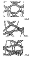
- Figures 1 to 5 show magnified schematic views of different versions of the knitted fabric of the flexible basic structure of the areal implant according to the invention.
- the figures are drawn on the basis of scanning electron microscope photographs taken at roughly 25 times magnification.
- Variant A of the knitted fabric according to Figure 1 has an approximate quadratic structure, the crosspiece length being about 3 mm in each case.
- Variant B of the knitted fabric according to Figure 2 also has an approximate quadratic structure. However, the crosspiece length is larger here and is about 5 mm.
- Variant C of the knitted fabric, shown in Figure 3 has differently sized openings or pores, the area of the large pores being greater than 0.5 nm 2 and that of the smaller pores being less than 0.5 mm 2 .
- Variants D and E of the knitted fabric, shown in Figures 4 and 5 have other structures.
- Variants A to E are all knitted from multifilament polypropylene, using three thread systems.
- the conventional implant net consists of monofilament polypropylene, using one thread system.
- Table 1 shows the number of courses per centimetre, the number of wales per centimetre, the yarn fineness, the dimensions of the pores larger than 0.5 mm 2 , the proportion of pores (relative to the total area of the knitted fabric or of the conventional implant net) and the thickness.
- variants A and B have a larger proportion of pores and a smaller thickness.
- variants A to E have a relatively low areal weight, which in all cases is below 50 g/m 2 and is thus clearly smaller than that of the conventional implant net.
- the seam tear-out force per centimetre of seam length, measured along and across the knitted fabric or the conventional implant net, is as a rule more than 16 N/cm, the value quoted by Klinge for the maximum wall stress at the edge of an abdominal tissue region.
- the stress-strain behaviour of the knitted fabrics or of the conventional implant net can be best described quantitatively using a plunger pressing test related to DIN 54307.
- material properties related to area are measured with such plunger pressing tests.
- Figure 6 shows a schematic view of a device for carrying out plunger pressing tests.
- a semispherical plunger 1, which is attached to a shank 2, is moved in the direction of the arrow, i.e. along the axis of symmetry.
- a sample 5 of the knitted fabric to be investigated or of a conventional implant net is clamped between an upper ring 3 and a lower ring 4.
- the plunger 1 When the plunger 1 is advanced in a downwards direction, it pushes the sample 5 in a downwards direction. The greater the deformation of the sample 5, the greater the force F exerted on the plunger 1 by the sample 5 becomes.
- the plunger radius is 50 mm.
- the internal radius of the upper ring 3 and of the lower ring 4 is 56.4 mm, so that the effective surface area of the sample 5 is 100 cm 2 .
- the deformation given in Table 1 arises which results from the change in length of the sample at r contact measured in the peripheral direction, relative to the corresponding peripheral length of the non-deformed sample. From the test data, it is also possible to calculate the elongation at break, also given in Table 1, which is higher than the deformation since the sample in the plunger pressing test tears, not at r contact , but in the middle region where it is more stretched than at r contact .
- Table 1 also shows the results of a strip tensile test carried out on samples of variants A to E and the conventional implant net. For this, the tearing force per centimetre of sample width (tearing strength) along the sample direction and the elongation at break are determined. It is, however, to be taken into consideration here that the values can be severely distorted by the test (contraction upon drawing), making the plunger pressing test more informative.
- the tearing strengths lie in the range from 25 to 45 N/cm and are therefore at least as large as the tearing strength of the fasciae quoted by Klinge (20 to 30 N/cm). The much higher tearing strength of the conventional implant net is again not necessary.
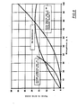
- Figure 7 shows a complete plunger force - plunger path length diagram, determined using a plunger pressing test, for the knitted fabric of variant B compared with the conventional implant net made of polypropylene (H).
- the plunger force - plunger path length diagrams as in Figure 7 can be converted into force-length change diagrams or into stress-strain diagrams. In the case of the latter, stress is to be understood as the force per centimetre of sample width.
- Figure 8 shows such a stress - strain diagram of the flexible basic structure according to variant A, as results from the plunger pressing test.
- a stress - strain diagram determined using rat musculature is also shown, which was not, however, obtained by a plunger pressing test, which was not possible to carry out with rat musculature because of the sample size required, but on the basis of a strip tensile test on a sample strip approx. 1 cm in width. Measurements on the rat musculature were taken at a musculature thickness which corresponds approximately to that of a human abdominal wall, wherein the spread, as in the case of any biological sample, can be correspondingly large.
- the forces required for variant A are smaller than for rat musculature, and for elongations of less than 50 %, even much smaller.
- a knitted fabric according to variant A implanted into muscle stretches with it during usual movements, without appreciable forces being necessary for this. Therefore, the implant does not have an inconvenient effect.
- the knitted fabric of the basic structure undergoes less pronounced further stretching than the tissue, so that the knitted fabric of the basic structure is able to absorb the forces.
- the transition between the two elongation or stretching regions takes place at a critical force which results from the point of intersection of the curves in Figure 8.
- the critical force defined in this way should be below the highest load which is allowable for the tissue region.
- Table 2 shows the plunger forces F measured in the plunger pressing test as a function of the plunger path length s for variants A to E, i.e. values as are shown graphically in Figure 7 for variant B.
- the values for the conventional implant net made of polypropylene (H) according to Table 1 and for another conventional implant net made of polyester (M) are also listed.
- the data for F max and for the plunger path length at F max are taken from Table 1. In the plunger pressing test initial damage to the investigated sample takes place at F max .
- F max is much larger for the conventional implant net made of polypropylene than for variants A to E.
- F max for the conventional implant net made of polyester is of the same order of magnitude as for variants A to E.
- the plunger force for variants A to E is much smaller than for the conventional implant net made of polyester, which again illustrates the superiority of the implant according to the invention.
- the force was not returned to zero in the plunger pressing tests (as in Figure 9), but operated at a residual force of 0.5 N. It is clear from Table 3 that variant B of the flexible basic structure of the implant according to the invention offers a clearly lower resistance to the alternating load, which is to simulate the movement of an abdominal wall, than do the conventional implant nets.
- Figure 10 shows a magnified schematic view of the flexible basic structure according to variant A, into which a multifilament thread made of polyglactin 910 is woven for stiffening.
- Figure 11 Shown in Figure 11 is a magnified schematic view of the flexible basic structure according to variant B which is provided with a coating of polyglactin 630.
- Polyglactin 630 is a copolymer of glycolide and lactide in the ratio 6:3 and, just like polyglactin 910, is resorbable.
- the flexible basic structure is stiffened by the woven-in thread or by the coating, as a result of which handling of the implant according to the invention during use, in particular during the operation, is much improved. Since the stiffening material is resorbable, the rigidity of the implant in the body of the patient decreases with time, until the implant has achieved the properties of the basic structure with its favourable stress/strain behaviour, as explained earlier.
- Table 4 compares the bending resistances of the knitted fabric according to variant A ( Figure 1), of the knitted fabric according to variant B ( Figure 2), of the knitted fabric according to variant A with stiffening thread (Figure 10), of the knitted fabric according to variant B with stiffening coating ( Figure 11) and of a conventional implant net made of polypropylene.
- the bending resistances quoted were determined in a three-point bending test with the supports 15 mm apart and a sample width of 15 mm.
- the conventional implant rated as good by users as regards handling, has a bending resistance of ca. 0.15 to 0.20 N/mm.
- the bending resistances of the stiffened knitted fabrics are clearly higher than those of the original basic structures and are between ca. 0.05 and 0.42 N/mm.
- the initial rigidity of the areal implant according to the invention can be varied within wide limits by means of the type, the quantity and the structure of the applied or incorporated stiffening resorbable material.
Abstract
Description
- The invention relates to an areal implant, in particular for abdominal wall closure.
- During an operation in the abdominal region, it is often necessary to strengthen the abdominal wall using an inserted areal implant. It is known to use nets made from the non-resorbable plastics polypropylene or polyester or from the slowly resorbable polyglactin 910 (a copolymer of glycolide and lactide in the ratio 9:1) for such implants. Metallic implants are also used.
- The known implant nets have some disadvantages. For example, they are relatively heavy, i.e. the areal weight is as a rule more than 50 g/m2 and predominantly even ca. 100 g/m2. If the implants are not resorbable, a relatively large quantity of foreign substance thus remains permanently in the body. In terms of tearing strength, the known implant nets are frequently over-sized, i.e. they have a much higher strength than is required from a physiological viewpoint. These properties, combined with the usual, net-like construction of the basic structure of the previously known implants, can mean that the well-being and the mobility of a patient who is fitted with such an implant are limited.
- Another disadvantage of the previously known areal implants is that, although they conform better to the abdominal wall after the operation if they are more flexible, they can then only be inserted with difficulty, since e.g. they fold readily. On the other hand, although a rigid implant is easy to handle, it can lead to problems in the long term after insertion into the abdominal wall, as already mentioned. The previously known areal implants are thus either too flexible for ease of working during an operation or too rigid for an unproblematical interaction with the abdominal wall into which they are inserted.
- It is thus the object of the invention to provide an areal implant, in particular for abdominal wall closure, which can be worked easily during an operation and which shows an elasticity behaviour in the long term which is matched to the tissue into which it is inserted.
- This object is achieved by an areal implant, in particular for abdominal wall closure, having the features of
claim 1. Advantageous embodiments result from the dependent claims. - The areal implant according to the invention has a flexible basic structure made from a knitted fabric comprising non-resorbable material or resorbable material or a combination of such materials. If resorbable material is used, the resorption time (i.e. the period after which the total mass of the implant has degraded in vivo) is at least 60 days, and/or the in vivo decrease in strength is so slow that 30 days after implantation the tearing strength is still at least 10 % of the initial tearing strength. Non-resorbable or slowly resorbable materials are used in order that the basic structure is stable in the longer term and a more certain healing success can be ensured.
- The term "knitted fabric" is to be understood here in the widest sense. It also includes, for example, knits and other mesh structures, i.e. essentially all textile materials which are not pure woven fabrics.
- The knitted fabric of the basic structure is designed to stretch more than the tissue region destined to receive the implant below a critical force and stretch less than this tissue region above the critical force. The critical force is below the highest load this tissue region can be submitted to. The flexible basic structure is thereby matched without problems to the usual movements of the tissue (e.g. of an abdominal wall) into which the areal implant is inserted or sewn. In the case of small forces, as occur during normal movements by the patient, the elasticity behaviour of the system consisting of an abdominal wall and the inserted implant is shaped by the abdominal wall. The implant thus does not act as a foreign body. If, on the other hand, the forces exceed the critical force, the implant absorbs the forces and thus prevents injury to the body tissue, e.g. the abdominal wall.
- According to the invention, the basic structure is stiffened by a synthetic resorbable material whose resorption time is less than that of the basic structure and preferably lies in the range from 2 days to 200 days. As a result, the areal implant is relatively firm and easy to handle during the operation (e.g. when cutting to size and inserting) but loses its then undesired rigidity after a relatively short time in the body tissue, because the stiffening synthetic material is resorbed.
- In a preferred version, the knitted fabric of the basic structure is constructed in such a way that it has stress/strain properties which can be quantified using a plunger pressing test, as stated in
claim 2. - The areal weight of the basic structure is preferably less than 50 g/m2. When suitable materials are used (see below), for an implant for abdominal wall closure of correspondingly low mass, a strength can be achieved which lies above the physiological framework data given by Klinge (U. Klinge, B. Klosterhalten, W. Limberg, A.P. bttinger, V. Schumpelick: Use of mesh materials in scar rupture; Change in the abdominal wall dynamics after mesh implantation; Poster, 162nd Convention of the Lower Rhine-Westphalian Surgeon's Association, 1995). According to him, the intra-abdominal pressure is 20 kPa (150 mm Hg) at most, the wall stress at the edge of an abdominal tissue region 16 N/cm at most and the tearing strength of the fasciae, 20 N/cm to 30 N/cm. An implant constructed in this way is thus able to absorb all forces occurring physiologically at a healthy abdominal wall and also offers an additional safety reserve. More stable and thus heavier basic structures offer no additional advantage, but can have the disadvantage of undesired rigidity mentioned at the beginning.
- The knitted fabric of the basic structure preferably has an approximate rectangular structure or approximate quadratic structure knitted from yarns. Honeycomb structures or structures with approximately circular openings or other polygonal structures are however also conceivable. Preferred versions of such knitted fabrics are explained in more detail in the description of the embodiments with the help of figures. The desired stress/strain behaviour can be achieved with knitted structures of this type, i.e. the basic structure stretches more than the tissue region destined to receive the implant below the critical force and less than this tissue region above the critical force, the critical force being below the highest load allowable for this tissue region.
- There are various possibilities for connecting the stiffening material to the basic structure. Thus, the stiffening material can e.g. have resorbable yarns or thin monofilaments woven into the basic structure, it can have a film which is applied to one side or both sides of the basic structure, or it can have a coating applied to the material of the knitted fabric. Combinations of these are also conceivable.
- Advantageous materials for the basic structure are e.g. polypropylene, polyester, polyglactin 910, polylactide yarns, polyglycolide yarns, poly-p-dioxanone yarns, but also copolymers, mixtures or combinations of such materials.
- Suitable as the stiffening material are e.g. yarns or films of poly-p-dioxanone, yarns or films of polyglactin (i.e. glycolide/lactide copolymers), yarns or films of polylactide, yarns or films of other copolymers of these materials, monofilaments of such materials (e.g. with thread thicknesses of 0.01 mm to 0.2 mm in diameter), coating waxes made from such materials, in particular from polyglactin 630, and others. mixtures of synthetic resorbable materials whose resorption time lies in the desired range can also be used for the stiffening material. If the stiffening material is of a textile nature, the result of the in vivo decrease in strength is that, after an implantation time of typically 2 to 50 days, the residual tearing strength is still about 10 % of the initial tearing strength.
- The material of the basic structure is preferably not dyed, in order that the basic structure, which does after all remain in the body for a long time or permanently after implantation, shows no undesired foreign body reaction as a result of the dye. On the other hand, it can be advantageous if the stiffening material is dyed. This does in fact permit a better visual check on the implant during the operation. During resorption the dye disappears, so that no dye remains in the body in the longer term and thus no undesired side-effects occur.
- The invention is described in more detail below with reference to embodiments and with the help of drawings. These show:
- Figure 1 a magnified schematic view of a first version of the flexible basic structure (variant A), magnified 25 times in part (a) and 15 times in part (b),
- Figure 2 a magnified (25 times) schematic view of another version of the flexible basic structure (variant B),
- Figure 3 a magnified (25 times) schematic view of another version of the flexible basic structure (variant C),
- Figure 4 a magnified (25 times) schematic view of another version of the flexible basic structure (variant D),
- Figure 5 a magnified (25 times) schematic view of another version of the flexible basic structure (variant E),
- Figure 6 a schematic view of a device for carrying out plunger pressing tests,
- Figure 7 the plunger force - plunger path length diagram, measured with the device according to Figure 6, of the flexible basic structure according to variant B compared with a conventional implant made of polypropylene (H),
- Figure 8 the stress-strain diagram of the flexible basic structure according to variant A, compared with rat musculature,
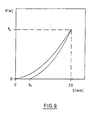
- Figure 9 a schematic plunger force - plunger path length diagram to explain the hysteresis behaviour of the flexible basic structure,
- Figure 10 a magnified (25 times) schematic view of the flexible basic structure according to variant A which is stiffened with a yarn made of polyglactin 910, and
- Figure 11 a magnified (25 times) schematic view of the flexible basic structure according to variant B which is stiffened with a resorbable coating made of polyglactin 630.
- Figures 1 to 5 show magnified schematic views of different versions of the knitted fabric of the flexible basic structure of the areal implant according to the invention. The figures are drawn on the basis of scanning electron microscope photographs taken at roughly 25 times magnification.
- Variant A of the knitted fabric according to Figure 1 has an approximate quadratic structure, the crosspiece length being about 3 mm in each case. Variant B of the knitted fabric according to Figure 2 also has an approximate quadratic structure. However, the crosspiece length is larger here and is about 5 mm. Variant C of the knitted fabric, shown in Figure 3, has differently sized openings or pores, the area of the large pores being greater than 0.5 nm2 and that of the smaller pores being less than 0.5 mm2. Variants D and E of the knitted fabric, shown in Figures 4 and 5, have other structures.
- It is clearly recognisable from Figures 1 to 5 that the majority of the pores are larger than 0.5 mn2. Thus, after implantation, the flexible basic structure of the areal implant can be grown through by tissue in satisfactory manner, which leads to a secure anchorage in the body of the patient and to a reliable absorption of forces by the implant.
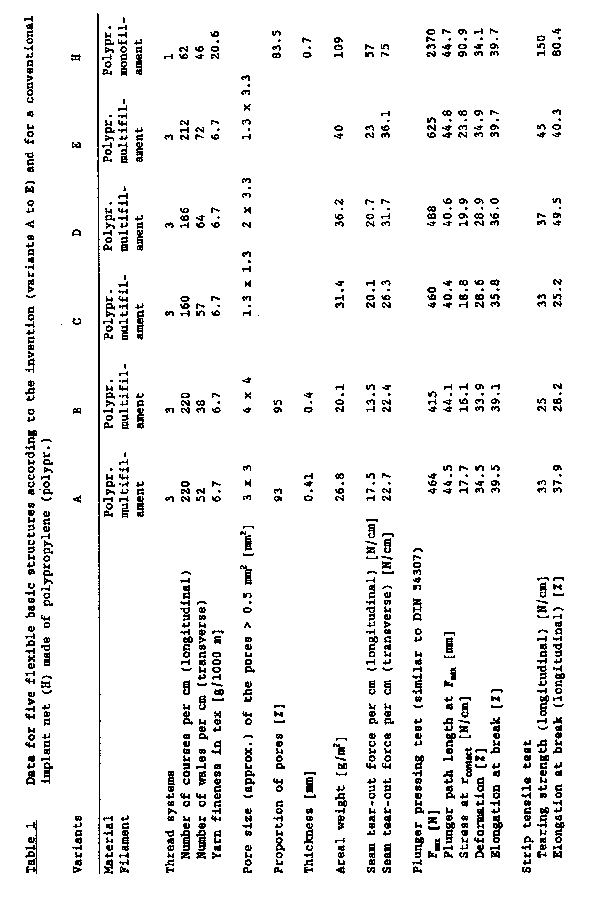
- Variants A to E are all knitted from multifilament polypropylene, using three thread systems. The conventional implant net consists of monofilament polypropylene, using one thread system. Table 1 shows the number of courses per centimetre, the number of wales per centimetre, the yarn fineness, the dimensions of the pores larger than 0.5 mm2, the proportion of pores (relative to the total area of the knitted fabric or of the conventional implant net) and the thickness. Compared with the conventional implant net, variants A and B have a larger proportion of pores and a smaller thickness. As Table 1 also shows, variants A to E have a relatively low areal weight, which in all cases is below 50 g/m2 and is thus clearly smaller than that of the conventional implant net.
- For variants A to E, the seam tear-out force per centimetre of seam length, measured along and across the knitted fabric or the conventional implant net, is as a rule more than 16 N/cm, the value quoted by Klinge for the maximum wall stress at the edge of an abdominal tissue region.
- The stress-strain behaviour of the knitted fabrics or of the conventional implant net can be best described quantitatively using a plunger pressing test related to DIN 54307. In the textile industry, material properties related to area are measured with such plunger pressing tests.
- Figure 6 shows a schematic view of a device for carrying out plunger pressing tests. A
semispherical plunger 1, which is attached to ashank 2, is moved in the direction of the arrow, i.e. along the axis of symmetry. Asample 5 of the knitted fabric to be investigated or of a conventional implant net is clamped between anupper ring 3 and a lower ring 4. When theplunger 1 is advanced in a downwards direction, it pushes thesample 5 in a downwards direction. The greater the deformation of thesample 5, the greater the force F exerted on theplunger 1 by thesample 5 becomes. The force F and the plunger path length s, which is a measure of the deformation of thesample 5, are measured, wherein s = 0 when the lowest point of theplunger 1 is located in the plane of thesample 5. With the device used for the plunger pressing tests the plunger radius is 50 mm. The internal radius of theupper ring 3 and of the lower ring 4 is 56.4 mm, so that the effective surface area of thesample 5 is 100 cm2. - Given in Table 1 for variants A to E and for the conventional implant net are the maximum force Fmax applied during the plunger pressing test, at which the first damage to the sample occurs (in the middle region of the sample), and the associated plunger path length smax. From this, the so-called stress at rcontact, which corresponds to the so-called wall stress in N/cm, can be calculated. In the sample, the stress at rcontact occurs along the circular line where, in the case of plunger path length smax, the sample region abutting the plunger passes into the sample edge region which does not touch the plunger directly and extends as far as the
rings 3, 4. At this stress, the deformation given in Table 1 arises which results from the change in length of the sample at rcontact measured in the peripheral direction, relative to the corresponding peripheral length of the non-deformed sample. From the test data, it is also possible to calculate the elongation at break, also given in Table 1, which is higher than the deformation since the sample in the plunger pressing test tears, not at rcontact, but in the middle region where it is more stretched than at rcontact. - It is clear from Table 1 that for all variants A to E the stress at rcontact is greater than or equal to 16 N/cm, i.e. at least as large as the maximum wall stress at the edge of an abdominal tissue region (16 N/cm) quoted by Klinge. The much greater value in the case of the conventional implant net is physiologically unnecessary.
- Table 1 also shows the results of a strip tensile test carried out on samples of variants A to E and the conventional implant net. For this, the tearing force per centimetre of sample width (tearing strength) along the sample direction and the elongation at break are determined. It is, however, to be taken into consideration here that the values can be severely distorted by the test (contraction upon drawing), making the plunger pressing test more informative.
- For variants A to E of the knitted fabric, the tearing strengths lie in the range from 25 to 45 N/cm and are therefore at least as large as the tearing strength of the fasciae quoted by Klinge (20 to 30 N/cm). The much higher tearing strength of the conventional implant net is again not necessary.
- Figure 7 shows a complete plunger force - plunger path length diagram, determined using a plunger pressing test, for the knitted fabric of variant B compared with the conventional implant net made of polypropylene (H). The curve for variant B ends at the values for Fmax and smax given in Table 1, whilst the curve for the conventional implant net is not shown in full, but stops at F = 500 N. It is clear to see that, for the implant of the invention according to variant B, the plunger force F is small even with relatively large plunger path lengths s. Only at larger values of s does the curve rise sharply. With the conventional implant net, the plunger force F is already large at average plunger path lengths s.
- The plunger force - plunger path length diagrams as in Figure 7 can be converted into force-length change diagrams or into stress-strain diagrams. In the case of the latter, stress is to be understood as the force per centimetre of sample width.
- Moreover, the change in length of the sample is related to the total length of the sample (before strain) and is thus independent of the total length of the sample itself. Figure 8 shows such a stress - strain diagram of the flexible basic structure according to variant A, as results from the plunger pressing test.
- A stress - strain diagram determined using rat musculature is also shown, which was not, however, obtained by a plunger pressing test, which was not possible to carry out with rat musculature because of the sample size required, but on the basis of a strip tensile test on a sample strip approx. 1 cm in width. Measurements on the rat musculature were taken at a musculature thickness which corresponds approximately to that of a human abdominal wall, wherein the spread, as in the case of any biological sample, can be correspondingly large.
- A narrow sample strip contracts in the tensile test, which leads to a much greater elongation at a given tensile force per strip width (stress) than if elongation takes place simultaneously in several spatial directions, as during the plunger pressing test. The curve for the rat musculature cannot therefore be compared directly with the stress - strain diagram obtained in the plunger pressing test for the flexible basic structure according to variant A. For this reason, another stress-strain diagram is shown for the flexible basic structure according to variant A which, as with the rat musculature, was determined using a strip tensile test, using a
sample strip 1 cm in width. Even at an elongation of 100 %, the sample had still not torn, which is not inconsistent with the elongation at break given in Table 1 for the strip tensile test, because the values in Table 1 apply to strips with a larger width. - In order to achieve an elongation up to about 78 %, the forces required for variant A are smaller than for rat musculature, and for elongations of less than 50 %, even much smaller. This means that a knitted fabric according to variant A implanted into muscle stretches with it during usual movements, without appreciable forces being necessary for this. Therefore, the implant does not have an inconvenient effect. However, if in the case of extreme loads, the forces which arise approach the highest load which is allowable for the tissue region into which the implant is inserted (which corresponds in Figure 8 to about 18 N/cm), the knitted fabric of the basic structure undergoes less pronounced further stretching than the tissue, so that the knitted fabric of the basic structure is able to absorb the forces. The transition between the two elongation or stretching regions takes place at a critical force which results from the point of intersection of the curves in Figure 8. The critical force defined in this way should be below the highest load which is allowable for the tissue region.
- The fact that in Figure 8 the critical force and the highest load which is allowable for the tissue region (to be more precise, the corresponding stresses) are approximately the same size is due to the tests with rat musculature which are difficult to carry out. Figure 8 is intended only to illustrate the two described elongation regions. Quantitative measurements on the flexible basic structures are better carried out using plunger pressing tests, and Klinge's data can for example be referred to for tissue, see above.
- Table 2 shows the plunger forces F measured in the plunger pressing test as a function of the plunger path length s for variants A to E, i.e. values as are shown graphically in Figure 7 for variant B. By way of comparison, the values for the conventional implant net made of polypropylene (H) according to Table 1 and for another conventional implant net made of polyester (M) are also listed. The data for Fmax and for the plunger path length at Fmax are taken from Table 1. In the plunger pressing test initial damage to the investigated sample takes place at Fmax.
Table 2 Plunger force F measured in the plunger pressing test related to DIN 54307 as a function of the plunger path length s, and Fmax (in N) and s(Fmax) (in mm) for five flexible basic structures according to the invention (variants A to E) and for two conventional implant nets made of polypropylene (H) and of polyester (M). A B C D E M H s [mm] F[N] F[N] F[N] F[N] F[N] F[N] F[N] 10 < 10 < 10 < 10 < 10 < 10 ca.10 ca.50 15 ca.15 ca.20 ca.10 ca.20 ca.10 ca.35 ca.135 20 ca.30 ca.35 ca.30 ca.40 ca.40 ca.85 ca.300 25 ca.70 ca.70 ca.75 ca.80 ca.80 ca.160 ca.600 30 ca.130 ca.130 ca.150 ca.170 ca.150 ca.280 Fmax 464 420 460 490 630 460 2370 s(Fmax) 45 44 40 41 45 37 45 - As already sheen, Fmax is much larger for the conventional implant net made of polypropylene than for variants A to E. Fmax for the conventional implant net made of polyester is of the same order of magnitude as for variants A to E. However, for the plunger path lengths up to 30 mm listed in Table 2, the plunger force for variants A to E is much smaller than for the conventional implant net made of polyester, which again illustrates the superiority of the implant according to the invention.
- Both the knitted fabric of the basic structure of the areal implant according to the invention and conventional implant nets show a hysteresis behaviour which can be determined in the plunger pressing test. The plunger force - plunger path length diagram in Figure 9 shows schematically how in the case of a new sample, the plunger force F, starting from the plunger path length s = 0, increases to a value F0 which is defined here as the value of the plunger force at a plunger path length of 20 mm. If the plunger is withdrawn, the plunger force already returns to zero at a plunger path length s1.
- Table 3 compares the force F0 and the plunger path length s1 during one plunger pressing test (n = 1) and after 5,000 plunger pressing tests (n = 5,000) for a conventional implant net made of polyglactin 910, a conventional implant net made of polypropylene and the knitted fabric of the basic structure according to variant B. In order to ensure a secure abutment of the sample against the plunger, the force was not returned to zero in the plunger pressing tests (as in Figure 9), but operated at a residual force of 0.5 N. It is clear from Table 3 that variant B of the flexible basic structure of the implant according to the invention offers a clearly lower resistance to the alternating load, which is to simulate the movement of an abdominal wall, than do the conventional implant nets.
Table 3 Hysteresis behaviour of different implants after n alternating loads, measured in the plunger pressing test at a plunger path length between 0 and 20 mm and a plunger residual force of 0.5 N; see text Implant n = 1 n = 5000 F0 [N] s1 [mm] F0 [N] s1 [mm] Conventional implant net made of polyglactin 910, coarse-meshed ca. 150 ca. 8 ca.114 ca.15.5 Conventional implant net made of polypropylene ca. 240 ca. 4 ca.164 ca.12.5 Basic structure according to the invention, variant B ca.45 ca.7.5 ca.30 ca.14.2 - Figure 10 shows a magnified schematic view of the flexible basic structure according to variant A, into which a multifilament thread made of polyglactin 910 is woven for stiffening. Shown in Figure 11 is a magnified schematic view of the flexible basic structure according to variant B which is provided with a coating of polyglactin 630. Polyglactin 630 is a copolymer of glycolide and lactide in the ratio 6:3 and, just like polyglactin 910, is resorbable.
- The flexible basic structure is stiffened by the woven-in thread or by the coating, as a result of which handling of the implant according to the invention during use, in particular during the operation, is much improved. Since the stiffening material is resorbable, the rigidity of the implant in the body of the patient decreases with time, until the implant has achieved the properties of the basic structure with its favourable stress/strain behaviour, as explained earlier.
- Table 4 compares the bending resistances of the knitted fabric according to variant A (Figure 1), of the knitted fabric according to variant B (Figure 2), of the knitted fabric according to variant A with stiffening thread (Figure 10), of the knitted fabric according to variant B with stiffening coating (Figure 11) and of a conventional implant net made of polypropylene. The bending resistances quoted were determined in a three-point bending test with the
supports 15 mm apart and a sample width of 15 mm. The conventional implant, rated as good by users as regards handling, has a bending resistance of ca. 0.15 to 0.20 N/mm. The bending resistances of the stiffened knitted fabrics are clearly higher than those of the original basic structures and are between ca. 0.05 and 0.42 N/mm. The latter value is even much higher than that for the previously known implant net.Table 4 Bending resistance of different implants, determined by comparative measurement in the three-point bending test with the supports 15 mm apart and a sample width of 15 mmImplant Bending resistance [N/mm] Basic structure according to the invention, variant A ca. 0.03 Basic structure according to the invention, variant B ca. 0.015 Basic structure according to the invention, variant A, stiffened by yarn (4 x 80 den) made of polyglactin 910 ca. 0.05 Basic structure according to the invention, variant B, stiffened by coating made of polyglactin 630 ca. 0.42 Conventional implant net made of polypropylene ca. 0.15 to 0.2 - The initial rigidity of the areal implant according to the invention can be varied within wide limits by means of the type, the quantity and the structure of the applied or incorporated stiffening resorbable material.
Claims (16)
- Areal implant, in particular for abdominal wall closure,- with a flexible basic structure made from a knitted fabric comprising non-resorbable material or resorbable material, which has a resorption time of at least 60 days and/or an in vivo decrease in strength which leads to a tearing strength remaining after 30 days which is at least 10 % of the initial tearing strength, or a combination of such materials,- wherein the knitted fabric of the basic structure is designed to stretch more than the tissue region destined to receive the implant below a critical force and stretch less than this tissue region above the critical force, the critical force being below the highest load allowable for this tissue region, and- with a synthetic resorbable material, which stiffens the basic structure, whose resorption time is less than that of the basic structure.
- Areal implant according to Claim 1, characterized in that the knitted fabric of the basic structure is constructed in such a way that a plunger pressing test carried out on an implant 100 cm2 in area with semispherical plunger 50 mm in radius produces a plunger force-plunger path length diagram which corresponds to a force-length change diagram, in which the plunger force is at most 15 N up to 10 mm plunger path length, less than 50 N at 20 mm plunger path length, and less than 200 N at 30 mm plunger path length, and in which the plunger force for plunger path lengths of more than 30 mm increases sharply to a value between 200 N and 1000 N at a plunger path length of 38 mm.
- Areal implant according to Claim 1 or 2, characterized in that the resorption time of the stiffening material is 2 days to 200 days.
- Areal implant according to one of claims 1 to 3, characterized in that the areal weight of the basic structure is less than 50 g/m2.
- Areal implant according to one of claims 1 to 4, characterized in that the knitted fabric has a honeycomb structure or approximate rectangular structure or approximate quadratic structure knitted from yarns.
- Areal implant according to one of claims 1 to 4, characterized in that the knitted fabric has a structure as is shown in one of Figures 1 to 5.
- Areal implant according to one of the preceding claims, characterized in that the knitted fabric has meshes with an inside width in the range from 1 mm to 8 mm.
- Areal implant according to one of the preceding claims, characterized in that the stiffening material has resorbable yarns, preferably monofilaments and/or multifilaments, knitted into the basic structure.
- Areal implant according to one of the preceding claims, characterized in that the stiffening material has a film which is applied to one side or both sides of the basic structure.
- Areal implant according to one of the preceding claims, characterized in that the stiffening material has a coating applied to the material of the knitted fabric.
- Areal implant according to Claim 10, characterized in that the coating comprises polyglactin 630.
- Areal implant according to one of the preceding claims, characterized in that the stiffening material comprises a material which is selected from the following group of materials: polymers based on caprolactone, polyglycolide, polylactide, poly-p-dioxanone, lactide/glycolide copolymers, lactide/caprolactone copolymers, glycolide/ caprolactone copolymers, glycolide/poly-p-dioxanone copolymers, glycolide/poly-p-dioxanone/lactide copolymers, other copolymers of the listed materials.
- Areal implant according to one of the preceding claims, characterized in that the material of the basic structure comprises polypropylene and/or polyester.
- Areal implant according to one of the preceding claims, characterized in that the material of the basic structure comprises a material which is selected from the group of the following materials: polylactide, polyglycolide, lactide/glycolide copolymers, preferably polyglactin 910, poly-p-dioxanone.
- Areal implant according to one of the preceding claims, characterized in that the material of the basic structure is not dyed.
- Areal implant according to one of the preceding claims, characterized in that the stiffening material is dyed.
Applications Claiming Priority (2)
| Application Number | Priority Date | Filing Date | Title |
|---|---|---|---|
| DE19613730 | 1996-03-26 | ||
| DE19613730A DE19613730C2 (en) | 1996-03-26 | 1996-03-26 | Flat implant for strengthening or closing body tissue |
Publications (4)
| Publication Number | Publication Date |
|---|---|
| EP0797962A2 true EP0797962A2 (en) | 1997-10-01 |
| EP0797962A3 EP0797962A3 (en) | 1997-11-05 |
| EP0797962B1 EP0797962B1 (en) | 2004-05-12 |
| EP0797962B2 EP0797962B2 (en) | 2009-09-02 |
Family
ID=7790607
Family Applications (1)
| Application Number | Title | Priority Date | Filing Date |
|---|---|---|---|
| EP97250072A Expired - Lifetime EP0797962B2 (en) | 1996-03-26 | 1997-03-13 | Areal implant |
Country Status (9)
| Country | Link |
|---|---|
| US (1) | US6162962A (en) |
| EP (1) | EP0797962B2 (en) |
| JP (1) | JP4450437B2 (en) |
| CN (1) | CN1163196C (en) |
| AU (1) | AU704334B2 (en) |
| BR (1) | BR9701466B8 (en) |
| CA (1) | CA2200801C (en) |
| DE (2) | DE19613730C2 (en) |
| ZA (1) | ZA972563B (en) |
Cited By (55)
| Publication number | Priority date | Publication date | Assignee | Title |
|---|---|---|---|---|
| WO1999005990A1 (en) * | 1997-08-01 | 1999-02-11 | Sofradim Production | Three-dimensional open-worked prosthetic fabric |
| WO1999051163A1 (en) * | 1998-04-03 | 1999-10-14 | Bionx Implants Oy | Hernia mesh |
| US6113641A (en) * | 1997-08-27 | 2000-09-05 | Ethicon, Inc. | Prosthesis for the obturation of a hernial canal |
| US6180848B1 (en) | 1997-08-27 | 2001-01-30 | Ethicon, Inc. | Prosthesis obturating device for the obturation of a hernial canal |
| WO2001015625A1 (en) * | 1999-08-31 | 2001-03-08 | Ethicon Gmbh | Reinforced areal implant |
| EP1099421A1 (en) * | 1999-11-10 | 2001-05-16 | DEUTSCHE INSTITUTE FÜR TEXTIL- UND FASERFORSCHUNG STUTTGART Stiftung des öffentlichen Rechts | Prosthetic patch and method of manufacture |
| US6241768B1 (en) | 1997-08-27 | 2001-06-05 | Ethicon, Inc. | Prosthetic device for the repair of a hernia |
| WO2001056499A1 (en) * | 2000-01-31 | 2001-08-09 | Ethicon Gmbh | Areal implant with x-ray-visible elements |
| FR2807937A1 (en) | 2000-04-20 | 2001-10-26 | Sofradim Production | Self-gripping prosthesis of knitted fabric for parietal reinforcement has outer monofilament layer with loops broken by fusion to make spikes |
| FR2807936A1 (en) | 2000-04-20 | 2001-10-26 | Sofradim Production | ABDOMINAL WALL REINFORCEMENT FOR THE TREATMENT OF INGUINAL HERNIA BY ANTERIOR VOLTAGE-FREE |
| WO2002019944A3 (en) * | 2000-09-04 | 2002-07-25 | Ethicon Gmbh | Flexible implant |
| WO2003092758A1 (en) * | 2002-05-03 | 2003-11-13 | Ethicon Gmbh | Surgical thread and surgical implant with the same |
| EP1541183A1 (en) * | 2003-11-26 | 2005-06-15 | Ethicon, Inc. | Prosthetic repair device |
| FR2869234A1 (en) * | 2004-04-21 | 2005-10-28 | Cousin Biotech Soc Par Actions | TEXTILE IMPLANT OF PARIETAL REFECTION |
| US7025063B2 (en) | 2000-09-07 | 2006-04-11 | Ams Research Corporation | Coated sling material |
| EP1674048A1 (en) * | 2004-12-23 | 2006-06-28 | Radi Medical Systems Ab | Mesh implant for use in reconstruction of soft tissue defects |
| WO2006084165A2 (en) * | 2005-02-04 | 2006-08-10 | Ams Research Corporation | Pelvic implants and related methods |
| EP1704832A2 (en) * | 2001-03-30 | 2006-09-27 | Mpathy Medical Devices Limited | Surgical implant |
| EP2002800A1 (en) * | 2007-06-11 | 2008-12-17 | Radi Medical Systems Ab | Mesh implant with an interlocking knitted structure |
| US7900484B2 (en) | 2006-10-19 | 2011-03-08 | C.R. Bard, Inc. | Prosthetic repair fabric |
| CN103386149A (en) * | 2013-07-09 | 2013-11-13 | 钟春燕 | Net abdominal wall defect repairing material with sustain-released pain relieving effect and preparation method thereof |
| DE102014012717A1 (en) | 2014-08-27 | 2016-03-03 | Johnson & Johnson Medical Gmbh | Surgical implant |
| US9445883B2 (en) | 2011-12-29 | 2016-09-20 | Sofradim Production | Barbed prosthetic knit and hernia repair mesh made therefrom as well as process for making said prosthetic knit |
| US9499927B2 (en) | 2012-09-25 | 2016-11-22 | Sofradim Production | Method for producing a prosthesis for reinforcing the abdominal wall |
| US9526603B2 (en) | 2011-09-30 | 2016-12-27 | Covidien Lp | Reversible stiffening of light weight mesh |
| US9554887B2 (en) | 2011-03-16 | 2017-01-31 | Sofradim Production | Prosthesis comprising a three-dimensional and openworked knit |
| US9566370B2 (en) | 2004-12-23 | 2017-02-14 | Novus Scientific Ab | Mesh implant for use in reconstruction of soft tissue defects |
| US9622843B2 (en) | 2011-07-13 | 2017-04-18 | Sofradim Production | Umbilical hernia prosthesis |
| US9668847B2 (en) | 2006-06-22 | 2017-06-06 | Novus Scientific Ab | Mesh implant for use in reconstruction of soft tissue defects |
| US9717825B2 (en) | 2004-12-23 | 2017-08-01 | Novus Scientific Ab | Mesh implant for use in reconstruction of soft tissue defects |
| US9750837B2 (en) | 2012-09-25 | 2017-09-05 | Sofradim Production | Haemostatic patch and method of preparation |
| US9839504B2 (en) | 2013-06-18 | 2017-12-12 | Covidien Lp | Implantable slings |
| US9839505B2 (en) | 2012-09-25 | 2017-12-12 | Sofradim Production | Prosthesis comprising a mesh and a strengthening means |
| US9877820B2 (en) | 2014-09-29 | 2018-01-30 | Sofradim Production | Textile-based prosthesis for treatment of inguinal hernia |
| US9931198B2 (en) | 2015-04-24 | 2018-04-03 | Sofradim Production | Prosthesis for supporting a breast structure |
| US9932695B2 (en) | 2014-12-05 | 2018-04-03 | Sofradim Production | Prosthetic porous knit |
| US9980802B2 (en) | 2011-07-13 | 2018-05-29 | Sofradim Production | Umbilical hernia prosthesis |
| US10070948B2 (en) | 2008-06-27 | 2018-09-11 | Sofradim Production | Biosynthetic implant for soft tissue repair |
| US10080639B2 (en) | 2011-12-29 | 2018-09-25 | Sofradim Production | Prosthesis for inguinal hernia |
| US10159555B2 (en) | 2012-09-28 | 2018-12-25 | Sofradim Production | Packaging for a hernia repair device |
| US10184032B2 (en) | 2015-02-17 | 2019-01-22 | Sofradim Production | Method for preparing a chitosan-based matrix comprising a fiber reinforcement member |
| US10213283B2 (en) | 2013-06-07 | 2019-02-26 | Sofradim Production | Textile-based prosthesis for laparoscopic surgery |
| US10327882B2 (en) | 2014-09-29 | 2019-06-25 | Sofradim Production | Whale concept—folding mesh for TIPP procedure for inguinal hernia |
| DE102007063214B4 (en) | 2007-12-20 | 2019-06-27 | Aesculap Ag | Flat implant, especially for hernia care |
| US10363690B2 (en) | 2012-08-02 | 2019-07-30 | Sofradim Production | Method for preparing a chitosan-based porous layer |
| US10368971B2 (en) | 2007-12-03 | 2019-08-06 | Sofradim Production | Implant for parastomal hernia |
| US10405960B2 (en) | 2013-06-07 | 2019-09-10 | Sofradim Production | Textile-based prothesis for laparoscopic surgery |
| US10549015B2 (en) | 2014-09-24 | 2020-02-04 | Sofradim Production | Method for preparing an anti-adhesion barrier film |
| US10646321B2 (en) | 2016-01-25 | 2020-05-12 | Sofradim Production | Prosthesis for hernia repair |
| US10675137B2 (en) | 2017-05-02 | 2020-06-09 | Sofradim Production | Prosthesis for inguinal hernia repair |
| US10682215B2 (en) | 2016-10-21 | 2020-06-16 | Sofradim Production | Method for forming a mesh having a barbed suture attached thereto and the mesh thus obtained |
| US10743976B2 (en) | 2015-06-19 | 2020-08-18 | Sofradim Production | Synthetic prosthesis comprising a knit and a non porous film and method for forming same |
| US10865505B2 (en) | 2009-09-04 | 2020-12-15 | Sofradim Production | Gripping fabric coated with a bioresorbable impenetrable layer |
| US10900153B2 (en) | 2017-05-02 | 2021-01-26 | Sofradim Production | Two-sides gripping knit |
| US11471257B2 (en) | 2018-11-16 | 2022-10-18 | Sofradim Production | Implants suitable for soft tissue repair |
Families Citing this family (68)
| Publication number | Priority date | Publication date | Assignee | Title |
|---|---|---|---|---|
| FR2732582B1 (en) * | 1995-04-04 | 1997-10-17 | Sgro Jean Claude | PARIETAL PROSTHETIC ELEMENT |
| US7238403B2 (en) * | 1997-03-07 | 2007-07-03 | Kx Industries, Lp | Composite for removing moisture, liquid and odors with anti-microbial capability |
| US5980564A (en) * | 1997-08-01 | 1999-11-09 | Schneider (Usa) Inc. | Bioabsorbable implantable endoprosthesis with reservoir |
| US6740122B1 (en) | 1998-09-11 | 2004-05-25 | C. R. Bard, Inc. | Preformed curved prosthesis that is adapted to the external iliac vessels |
| US6723133B1 (en) | 1998-09-11 | 2004-04-20 | C. R. Bard, Inc. | Performed curved prosthesis having a reduced incidence of developing wrinkles or folds |
| DE19906172C1 (en) * | 1999-02-08 | 2000-07-13 | Ethicon Gmbh | Resorbable implant used for inducing tissue formation, especially in bone regeneration, has specific density and porosity properties |
| DE19912360A1 (en) | 1999-03-19 | 2000-09-21 | Aesculap Ag & Co Kg | Strand-shaped implant made of resorbable polymer material, process for its production and use in surgery |
| DE19959088A1 (en) * | 1999-12-08 | 2001-06-13 | Inst Textil & Faserforschung | Medical device, process for its manufacture and use |
| FR2811218B1 (en) | 2000-07-05 | 2003-02-28 | Patrice Suslian | IMPLANTABLE DEVICE FOR CORRECTING URINARY INCONTINENCE |
| US6592515B2 (en) | 2000-09-07 | 2003-07-15 | Ams Research Corporation | Implantable article and method |
| DE10046119A1 (en) | 2000-09-15 | 2002-03-28 | Inst Textil & Faserforschung | Medical bioresorbable implant, method of manufacture and use |
| US20060205995A1 (en) | 2000-10-12 | 2006-09-14 | Gyne Ideas Limited | Apparatus and method for treating female urinary incontinence |
| GB0025068D0 (en) | 2000-10-12 | 2000-11-29 | Browning Healthcare Ltd | Apparatus and method for treating female urinary incontinence |
| US8167785B2 (en) | 2000-10-12 | 2012-05-01 | Coloplast A/S | Urethral support system |
| DE10123934A1 (en) * | 2001-05-17 | 2002-12-05 | Ethicon Gmbh | Flat implant |
| EP1402906A4 (en) * | 2001-06-15 | 2007-04-25 | Gunze Kk | Synechia inhibitory material |
| DE10153334B4 (en) * | 2001-10-29 | 2004-04-29 | Ethicon Gmbh | Flat implant |
| DE10155842A1 (en) * | 2001-11-14 | 2003-05-28 | Ethicon Gmbh | Flat implant |
| US6790213B2 (en) | 2002-01-07 | 2004-09-14 | C.R. Bard, Inc. | Implantable prosthesis |
| DE10220368A1 (en) * | 2002-05-07 | 2003-12-04 | Biotissue Technologies Ag | Implant comprising transplant tissue cells in a porous resorbable matrix, especially useful for cartilage or bone transplantation, includes one or more stiffening elements for increasing compressive stability |
| AU2003249310A1 (en) * | 2002-07-17 | 2004-02-02 | Proxy Biomedical Limited | Soft tissue implants and methods for making same |
| CA2492630C (en) | 2002-08-02 | 2009-01-13 | C.R. Bard, Inc. | Self anchoring sling and introducer system |
| DE10243967A1 (en) * | 2002-09-20 | 2004-04-15 | Adiam Life Science Ag | Vascular prosthesis or tissue patch made of biocompatible polyurethane and method for improving the elastic modulus of these workpieces |
| US8142515B2 (en) * | 2002-11-04 | 2012-03-27 | Sofradim Production | Prosthesis for reinforcement of tissue structures |
| GB0307082D0 (en) | 2003-03-27 | 2003-04-30 | Gyne Ideas Ltd | Drug delivery device and method |
| US8545386B2 (en) | 2003-08-14 | 2013-10-01 | Boston Scientific Scimed, Inc. | Surgical slings |
| US20050070930A1 (en) * | 2003-09-30 | 2005-03-31 | Gene W. Kammerer | Implantable surgical mesh |
| CA2563347C (en) | 2004-04-20 | 2014-01-14 | Genzyme Corporation | Surgical mesh-like implant |
| GB0411360D0 (en) | 2004-05-21 | 2004-06-23 | Mpathy Medical Devices Ltd | Implant |
| US8298290B2 (en) | 2004-09-20 | 2012-10-30 | Davol, Inc. | Implantable prosthesis for soft tissue repair |
| JP4827838B2 (en) * | 2004-12-29 | 2011-11-30 | サムヤン コーポレーション | Monofilament, mesh for deentering surgery with improved flexibility and biocompatibility using the same, and method for producing the same |
| DE102005009356A1 (en) | 2005-03-01 | 2006-09-07 | Ethicon Gmbh | Surgical implant |
| CA2601449A1 (en) * | 2005-03-22 | 2006-09-28 | Tyco Healthcare Group, Lp | Mesh implant |
| CA2601156A1 (en) * | 2005-03-22 | 2006-09-28 | Tyco Healthcare Group Lp | Bioactive wide-weave mesh |
| WO2007070141A1 (en) * | 2005-09-12 | 2007-06-21 | Proxy Biomedical Limited | Soft tissue implants and methods for making same |
| DE102006011903A1 (en) | 2006-03-09 | 2007-09-13 | Aesculap Ag & Co. Kg | Flat implant, especially hernia mesh |
| CN101627525B (en) | 2006-12-27 | 2012-06-13 | 东芝开利株式会社 | Winding method for stator, and permanent-magnet electric motor |
| US8016841B2 (en) | 2007-06-11 | 2011-09-13 | Novus Scientific Pte. Ltd. | Mesh implant with an interlocking knitted structure |
| EP2185209A2 (en) * | 2007-08-03 | 2010-05-19 | Nicast Ltd. | Fibrous surgically implantable mesh |
| DE102007062273A1 (en) | 2007-12-14 | 2009-06-18 | Aesculap Ag | Fluorinated implant |
| US8206632B2 (en) * | 2007-12-18 | 2012-06-26 | Ethicon, Inc. | Methods of making composite prosthetic devices having improved bond strength |
| EP2344049B1 (en) | 2008-10-03 | 2021-01-27 | C.R.Bard, Inc. | Implantable prosthesis |
| EP2549947B1 (en) | 2010-03-24 | 2017-12-13 | Covidien LP | Combination three-dimensional surgical implant |
| US20110301717A1 (en) * | 2010-06-03 | 2011-12-08 | Hilton Becker | Supporting and Forming Transitional Material for Use in Supporting Prosthesis Devices, Implants and to Provide Structure in a Human Body |
| US8821585B2 (en) * | 2010-06-14 | 2014-09-02 | Ethicon, Inc. | Composite anisotropic tissue reinforcing implants having alignment markers and methods of manufacturing same |
| FR2962646B1 (en) | 2010-07-16 | 2012-06-22 | Sofradim Production | PROSTHETIC WITH RADIO OPAQUE ELEMENT |
| US9861590B2 (en) | 2010-10-19 | 2018-01-09 | Covidien Lp | Self-supporting films for delivery of therapeutic agents |
| US9561093B2 (en) * | 2010-10-28 | 2017-02-07 | Novus Scientific Ab | Elastically deformable and resorbable medical mesh implant |
| US8579924B2 (en) | 2011-07-26 | 2013-11-12 | Covidien Lp | Implantable devices including a mesh and a pivotable film |
| US9782957B2 (en) | 2011-08-24 | 2017-10-10 | Covidien Lp | Medical device films |
| US8932621B2 (en) | 2011-10-25 | 2015-01-13 | Covidien Lp | Implantable film/mesh composite |
| US9179994B2 (en) | 2011-10-25 | 2015-11-10 | Covidien Lp | Implantable film/mesh composite |
| US9005308B2 (en) | 2011-10-25 | 2015-04-14 | Covidien Lp | Implantable film/mesh composite for passage of tissue therebetween |
| US9080263B2 (en) | 2012-02-10 | 2015-07-14 | Novus Scientific Ab | Multifilaments with time-dependent characteristics, and medical products made from such multifilaments |
| EP2626454B1 (en) | 2012-02-10 | 2014-08-13 | Novus Scientific AB | Multifilaments with time-dependent characteristics and medical products made thereof |
| US10206769B2 (en) | 2012-03-30 | 2019-02-19 | Covidien Lp | Implantable devices including a film providing folding characteristics |
| CN111419467B (en) * | 2012-04-06 | 2022-11-15 | 聚合-医药有限公司 | Polymer network products, methods of manufacture and uses thereof |
| FR2992662B1 (en) | 2012-06-28 | 2014-08-08 | Sofradim Production | KNIT WITH PICOTS |
| FR2992547B1 (en) | 2012-06-29 | 2015-04-24 | Sofradim Production | PROSTHETIC FOR HERNIA |
| US10709539B2 (en) | 2013-02-01 | 2020-07-14 | Novus Scientific Ab | Three-dimensional polymeric medical implants |
| JP6406806B2 (en) * | 2013-09-12 | 2018-10-17 | 旭化成株式会社 | Artificial fiber cloth |
| US20150351889A1 (en) | 2014-06-05 | 2015-12-10 | Vivex Biomedical Inc. | Dynamic Biometric Mesh |
| EP3002580B1 (en) | 2014-09-30 | 2019-09-11 | Sofradim Production | Assessment of shear forces distribution at fixation points of textile-based implants |
| JP6932708B2 (en) * | 2015-11-04 | 2021-09-08 | ポリ−メッド インコーポレイテッド | Time-dependent biological tissue scaffolding |
| PL3940129T3 (en) * | 2016-01-14 | 2023-12-18 | Teijin Limited | Sealed fabric for use as a medical material |
| EP3252737A1 (en) | 2016-06-03 | 2017-12-06 | Sofradim Production | Abdominal model for laparoscopic abdominal wall repair/reconstruction simulation |
| US11413129B2 (en) | 2020-06-19 | 2022-08-16 | Davol Inc. | Implantable prosthesis |
| EP4262575A1 (en) | 2020-12-21 | 2023-10-25 | Ethicon, Inc. | Adaptive sutures dynamically changing wound holding properties post-implantation |
Citations (4)
| Publication number | Priority date | Publication date | Assignee | Title |
|---|---|---|---|---|
| US4633873A (en) † | 1984-04-26 | 1987-01-06 | American Cyanamid Company | Surgical repair mesh |
| US4655221A (en) * | 1985-05-06 | 1987-04-07 | American Cyanamid Company | Method of using a surgical repair mesh |
| WO1987007495A1 (en) * | 1986-06-09 | 1987-12-17 | Coors Biomedical Company | Biocompatible particles and cloth-like article made therefrom |
| DE3830005C1 (en) * | 1988-08-31 | 1989-11-02 | Ethicon Gmbh & Co Kg, 2000 Norderstedt, De | Sheet-like implant |
Family Cites Families (8)
| Publication number | Priority date | Publication date | Assignee | Title |
|---|---|---|---|---|
| US4871365A (en) * | 1985-04-25 | 1989-10-03 | American Cyanamid Company | Partially absorbable prosthetic tubular article having an external support |
| FI75493C (en) * | 1985-05-08 | 1988-07-11 | Materials Consultants Oy | SJAELVARMERAT ABSORBERBART PURCHASING SYNTHESIS. |
| EP0312494A3 (en) * | 1987-10-16 | 1991-01-16 | Institut Straumann Ag | Alloplastic material for building of a part of an artificial soft tissue or reinforcement of a part of a natural soft tissue |
| US5198280A (en) * | 1990-10-25 | 1993-03-30 | Allied-Signal Inc. | Three dimensional fiber structures having improved penetration resistance |
| US5185195A (en) * | 1990-11-19 | 1993-02-09 | Allied-Signal Inc. | Constructions having improved penetration resistance |
| EP0692227A1 (en) * | 1994-07-11 | 1996-01-17 | SULZER Medizinaltechnik AG | Sheet implant |
| GB9414746D0 (en) * | 1994-07-21 | 1994-09-07 | Vascutek Ltd | Prosthetic material |
| US5569273A (en) * | 1995-07-13 | 1996-10-29 | C. R. Bard, Inc. | Surgical mesh fabric |
-
1996
- 1996-03-26 DE DE19613730A patent/DE19613730C2/en not_active Revoked
-
1997
- 1997-03-13 EP EP97250072A patent/EP0797962B2/en not_active Expired - Lifetime
- 1997-03-13 DE DE69729021T patent/DE69729021T3/en not_active Expired - Lifetime
- 1997-03-24 CA CA002200801A patent/CA2200801C/en not_active Expired - Lifetime
- 1997-03-24 AU AU16485/97A patent/AU704334B2/en not_active Expired
- 1997-03-25 ZA ZA972563A patent/ZA972563B/en unknown
- 1997-03-25 US US08/823,914 patent/US6162962A/en not_active Expired - Lifetime
- 1997-03-25 JP JP08864497A patent/JP4450437B2/en not_active Expired - Lifetime
- 1997-03-25 BR BRPI9701466A patent/BR9701466B8/en not_active IP Right Cessation
- 1997-03-26 CN CNB971112037A patent/CN1163196C/en not_active Expired - Lifetime
Patent Citations (4)
| Publication number | Priority date | Publication date | Assignee | Title |
|---|---|---|---|---|
| US4633873A (en) † | 1984-04-26 | 1987-01-06 | American Cyanamid Company | Surgical repair mesh |
| US4655221A (en) * | 1985-05-06 | 1987-04-07 | American Cyanamid Company | Method of using a surgical repair mesh |
| WO1987007495A1 (en) * | 1986-06-09 | 1987-12-17 | Coors Biomedical Company | Biocompatible particles and cloth-like article made therefrom |
| DE3830005C1 (en) * | 1988-08-31 | 1989-11-02 | Ethicon Gmbh & Co Kg, 2000 Norderstedt, De | Sheet-like implant |
Non-Patent Citations (2)
| Title |
|---|
| A. Pans et al. European Surgence Research EURSURGRES 1992,24:54-60 † |
| Kunststoffe und Elastomere in der Medizin, herausgegeben von Prof. Heinrich Planck, 1993 Kohlhammer Verlag Stuttgart, insbesondere S. 71-77 † |
Cited By (98)
| Publication number | Priority date | Publication date | Assignee | Title |
|---|---|---|---|---|
| US6443964B1 (en) | 1997-08-01 | 2002-09-03 | Sofradim Production | Three-dimensional open-worked prosthetic fabric |
| WO1999005990A1 (en) * | 1997-08-01 | 1999-02-11 | Sofradim Production | Three-dimensional open-worked prosthetic fabric |
| US6113641A (en) * | 1997-08-27 | 2000-09-05 | Ethicon, Inc. | Prosthesis for the obturation of a hernial canal |
| US6180848B1 (en) | 1997-08-27 | 2001-01-30 | Ethicon, Inc. | Prosthesis obturating device for the obturation of a hernial canal |
| US6241768B1 (en) | 1997-08-27 | 2001-06-05 | Ethicon, Inc. | Prosthetic device for the repair of a hernia |
| WO1999051163A1 (en) * | 1998-04-03 | 1999-10-14 | Bionx Implants Oy | Hernia mesh |
| US6319264B1 (en) | 1998-04-03 | 2001-11-20 | Bionx Implants Oy | Hernia mesh |
| WO2001015625A1 (en) * | 1999-08-31 | 2001-03-08 | Ethicon Gmbh | Reinforced areal implant |
| US6966918B1 (en) | 1999-08-31 | 2005-11-22 | Ethicon G.M.B.H. | Reinforced areal implant |
| EP1099421A1 (en) * | 1999-11-10 | 2001-05-16 | DEUTSCHE INSTITUTE FÜR TEXTIL- UND FASERFORSCHUNG STUTTGART Stiftung des öffentlichen Rechts | Prosthetic patch and method of manufacture |
| EP1099422A1 (en) * | 1999-11-10 | 2001-05-16 | DEUTSCHE INSTITUTE FÜR TEXTIL- UND FASERFORSCHUNG STUTTGART Stiftung des öffentlichen Rechts | Hernia patch and method of manufacture |
| WO2001056499A1 (en) * | 2000-01-31 | 2001-08-09 | Ethicon Gmbh | Areal implant with x-ray-visible elements |
| FR2807936A1 (en) | 2000-04-20 | 2001-10-26 | Sofradim Production | ABDOMINAL WALL REINFORCEMENT FOR THE TREATMENT OF INGUINAL HERNIA BY ANTERIOR VOLTAGE-FREE |
| US6596002B2 (en) | 2000-04-20 | 2003-07-22 | Sofradim Production | Abdominal wall reinforcement for the treatment of inguinal hernias by an anterior route |
| EP2143836A1 (en) | 2000-04-20 | 2010-01-13 | Sofradim Production | Reinforcement implant for treatment of parietal defects |
| US7331199B2 (en) | 2000-04-20 | 2008-02-19 | Sofradim Production | Adhering prosthetic knitting fabric, method for making same and reinforcement implant for treating parietal deficiencies |
| FR2807937A1 (en) | 2000-04-20 | 2001-10-26 | Sofradim Production | Self-gripping prosthesis of knitted fabric for parietal reinforcement has outer monofilament layer with loops broken by fusion to make spikes |
| WO2002019944A3 (en) * | 2000-09-04 | 2002-07-25 | Ethicon Gmbh | Flexible implant |
| AU2001291758B2 (en) * | 2000-09-04 | 2007-03-15 | Johnson & Johnson Medical Gmbh | Flexible implant |
| US8147478B2 (en) | 2000-09-07 | 2012-04-03 | Ams Research Corporation | Coated sling material |
| US7025063B2 (en) | 2000-09-07 | 2006-04-11 | Ams Research Corporation | Coated sling material |
| EP1704832A3 (en) * | 2001-03-30 | 2006-12-06 | Mpathy Medical Devices Limited | Surgical implant |
| EP1704832A2 (en) * | 2001-03-30 | 2006-09-27 | Mpathy Medical Devices Limited | Surgical implant |
| WO2003092758A1 (en) * | 2002-05-03 | 2003-11-13 | Ethicon Gmbh | Surgical thread and surgical implant with the same |
| EP1541183A1 (en) * | 2003-11-26 | 2005-06-15 | Ethicon, Inc. | Prosthetic repair device |
| EP1591134A1 (en) * | 2004-04-21 | 2005-11-02 | Cousin Biotech | Textile implant for parietal refection |
| FR2869234A1 (en) * | 2004-04-21 | 2005-10-28 | Cousin Biotech Soc Par Actions | TEXTILE IMPLANT OF PARIETAL REFECTION |
| EP1674048A1 (en) * | 2004-12-23 | 2006-06-28 | Radi Medical Systems Ab | Mesh implant for use in reconstruction of soft tissue defects |
| US9750854B2 (en) | 2004-12-23 | 2017-09-05 | Novus Scientific Ab | Mesh implant for use in reconstruction of soft tissue defects |
| US9717825B2 (en) | 2004-12-23 | 2017-08-01 | Novus Scientific Ab | Mesh implant for use in reconstruction of soft tissue defects |
| US9566370B2 (en) | 2004-12-23 | 2017-02-14 | Novus Scientific Ab | Mesh implant for use in reconstruction of soft tissue defects |
| US10342653B2 (en) | 2004-12-23 | 2019-07-09 | Novus Scientific Ab | Mesh implant for use in reconstruction of soft tissue defects |
| WO2006084165A2 (en) * | 2005-02-04 | 2006-08-10 | Ams Research Corporation | Pelvic implants and related methods |
| US8585576B2 (en) | 2005-02-04 | 2013-11-19 | Ams Research Corporation | Pelvic implants and related methods |
| WO2006084165A3 (en) * | 2005-02-04 | 2007-12-06 | Ams Res Corp | Pelvic implants and related methods |
| US9452038B2 (en) | 2005-02-04 | 2016-09-27 | Boston Scientific Scimed, Inc. | Pelvic implants and related methods |
| US7905825B2 (en) | 2005-02-04 | 2011-03-15 | AMS Research Foundation | Pelvic implants and related methods |
| US9668847B2 (en) | 2006-06-22 | 2017-06-06 | Novus Scientific Ab | Mesh implant for use in reconstruction of soft tissue defects |
| US7900484B2 (en) | 2006-10-19 | 2011-03-08 | C.R. Bard, Inc. | Prosthetic repair fabric |
| EP2002800A1 (en) * | 2007-06-11 | 2008-12-17 | Radi Medical Systems Ab | Mesh implant with an interlocking knitted structure |
| US10368971B2 (en) | 2007-12-03 | 2019-08-06 | Sofradim Production | Implant for parastomal hernia |
| DE102007063214B4 (en) | 2007-12-20 | 2019-06-27 | Aesculap Ag | Flat implant, especially for hernia care |
| US10070948B2 (en) | 2008-06-27 | 2018-09-11 | Sofradim Production | Biosynthetic implant for soft tissue repair |
| US10865505B2 (en) | 2009-09-04 | 2020-12-15 | Sofradim Production | Gripping fabric coated with a bioresorbable impenetrable layer |
| US9554887B2 (en) | 2011-03-16 | 2017-01-31 | Sofradim Production | Prosthesis comprising a three-dimensional and openworked knit |
| US10472750B2 (en) | 2011-03-16 | 2019-11-12 | Sofradim Production | Prosthesis comprising a three-dimensional and openworked knit |
| US11612472B2 (en) | 2011-03-16 | 2023-03-28 | Sofradim Production | Prosthesis comprising a three-dimensional and openworked knit |
| US11903807B2 (en) | 2011-07-13 | 2024-02-20 | Sofradim Production | Umbilical hernia prosthesis |
| US9622843B2 (en) | 2011-07-13 | 2017-04-18 | Sofradim Production | Umbilical hernia prosthesis |
| US10709538B2 (en) | 2011-07-13 | 2020-07-14 | Sofradim Production | Umbilical hernia prosthesis |
| US11039912B2 (en) | 2011-07-13 | 2021-06-22 | Sofradim Production | Umbilical hernia prosthesis |
| US9980802B2 (en) | 2011-07-13 | 2018-05-29 | Sofradim Production | Umbilical hernia prosthesis |
| US9526603B2 (en) | 2011-09-30 | 2016-12-27 | Covidien Lp | Reversible stiffening of light weight mesh |
| US11266489B2 (en) | 2011-12-29 | 2022-03-08 | Sofradim Production | Barbed prosthetic knit and hernia repair mesh made therefrom as well as process for making said prosthetic knit |
| US9445883B2 (en) | 2011-12-29 | 2016-09-20 | Sofradim Production | Barbed prosthetic knit and hernia repair mesh made therefrom as well as process for making said prosthetic knit |
| US11925543B2 (en) | 2011-12-29 | 2024-03-12 | Sofradim Production | Barbed prosthetic knit and hernia repair mesh made therefrom as well as process for making said prosthetic knit |
| US10080639B2 (en) | 2011-12-29 | 2018-09-25 | Sofradim Production | Prosthesis for inguinal hernia |
| US10342652B2 (en) | 2011-12-29 | 2019-07-09 | Sofradim Production | Barbed prosthetic knit and hernia repair mesh made therefrom as well as process for making said prosthetic knit |
| US11471256B2 (en) | 2011-12-29 | 2022-10-18 | Sofradim Production | Prosthesis for inguinal hernia |
| US10363690B2 (en) | 2012-08-02 | 2019-07-30 | Sofradim Production | Method for preparing a chitosan-based porous layer |
| US9839505B2 (en) | 2012-09-25 | 2017-12-12 | Sofradim Production | Prosthesis comprising a mesh and a strengthening means |
| US9499927B2 (en) | 2012-09-25 | 2016-11-22 | Sofradim Production | Method for producing a prosthesis for reinforcing the abdominal wall |
| US9750837B2 (en) | 2012-09-25 | 2017-09-05 | Sofradim Production | Haemostatic patch and method of preparation |
| US10159555B2 (en) | 2012-09-28 | 2018-12-25 | Sofradim Production | Packaging for a hernia repair device |
| US10213283B2 (en) | 2013-06-07 | 2019-02-26 | Sofradim Production | Textile-based prosthesis for laparoscopic surgery |
| US11304790B2 (en) | 2013-06-07 | 2022-04-19 | Sofradim Production | Textile-based prothesis for laparoscopic surgery |
| US10405960B2 (en) | 2013-06-07 | 2019-09-10 | Sofradim Production | Textile-based prothesis for laparoscopic surgery |
| US11622845B2 (en) | 2013-06-07 | 2023-04-11 | Sofradim Production | Textile-based prothesis for laparoscopic surgery |
| US9839504B2 (en) | 2013-06-18 | 2017-12-12 | Covidien Lp | Implantable slings |
| CN103386149A (en) * | 2013-07-09 | 2013-11-13 | 钟春燕 | Net abdominal wall defect repairing material with sustain-released pain relieving effect and preparation method thereof |
| US10433942B2 (en) | 2014-08-27 | 2019-10-08 | Johnson & Johnson Medical Gmbh | Surgical implant |
| DE102014012717A1 (en) | 2014-08-27 | 2016-03-03 | Johnson & Johnson Medical Gmbh | Surgical implant |
| US10549015B2 (en) | 2014-09-24 | 2020-02-04 | Sofradim Production | Method for preparing an anti-adhesion barrier film |
| US11291536B2 (en) | 2014-09-29 | 2022-04-05 | Sofradim Production | Whale concept-folding mesh for TIPP procedure for inguinal hernia |
| US9877820B2 (en) | 2014-09-29 | 2018-01-30 | Sofradim Production | Textile-based prosthesis for treatment of inguinal hernia |
| US10327882B2 (en) | 2014-09-29 | 2019-06-25 | Sofradim Production | Whale concept—folding mesh for TIPP procedure for inguinal hernia |
| US11589974B2 (en) | 2014-09-29 | 2023-02-28 | Sofradim Production | Textile-based prosthesis for treatment of inguinal hernia |
| US10653508B2 (en) | 2014-09-29 | 2020-05-19 | Sofradim Production | Textile-based prosthesis for treatment of inguinal hernia |
| US11713526B2 (en) | 2014-12-05 | 2023-08-01 | Sofradim Production | Prosthetic porous knit |
| US9932695B2 (en) | 2014-12-05 | 2018-04-03 | Sofradim Production | Prosthetic porous knit |
| US10745835B2 (en) | 2014-12-05 | 2020-08-18 | Sofradim Production | Prosthetic porous knit |
| US11359313B2 (en) | 2014-12-05 | 2022-06-14 | Sofradim Production | Prosthetic porous knit |
| US10815345B2 (en) | 2015-02-17 | 2020-10-27 | Sofradim Production | Method for preparing a chitosan-based matrix comprising a fiber reinforcement member |
| US10184032B2 (en) | 2015-02-17 | 2019-01-22 | Sofradim Production | Method for preparing a chitosan-based matrix comprising a fiber reinforcement member |
| US11439498B2 (en) | 2015-04-24 | 2022-09-13 | Sofradim Production | Prosthesis for supporting a breast structure |
| US10660741B2 (en) | 2015-04-24 | 2020-05-26 | Sofradim Production | Prosthesis for supporting a breast structure |
| US9931198B2 (en) | 2015-04-24 | 2018-04-03 | Sofradim Production | Prosthesis for supporting a breast structure |
| US11826242B2 (en) | 2015-06-19 | 2023-11-28 | Sofradim Production | Synthetic prosthesis comprising a knit and a non porous film and method for forming same |
| US10743976B2 (en) | 2015-06-19 | 2020-08-18 | Sofradim Production | Synthetic prosthesis comprising a knit and a non porous film and method for forming same |
| US11389282B2 (en) | 2016-01-25 | 2022-07-19 | Sofradim Production | Prosthesis for hernia repair |
| US10646321B2 (en) | 2016-01-25 | 2020-05-12 | Sofradim Production | Prosthesis for hernia repair |
| US11696819B2 (en) | 2016-10-21 | 2023-07-11 | Sofradim Production | Method for forming a mesh having a barbed suture attached thereto and the mesh thus obtained |
| US10682215B2 (en) | 2016-10-21 | 2020-06-16 | Sofradim Production | Method for forming a mesh having a barbed suture attached thereto and the mesh thus obtained |
| US10900153B2 (en) | 2017-05-02 | 2021-01-26 | Sofradim Production | Two-sides gripping knit |
| US11672636B2 (en) | 2017-05-02 | 2023-06-13 | Sofradim Production | Prosthesis for inguinal hernia repair |
| US11555262B2 (en) | 2017-05-02 | 2023-01-17 | Sofradim Production | Two-sides gripping knit |
| US10675137B2 (en) | 2017-05-02 | 2020-06-09 | Sofradim Production | Prosthesis for inguinal hernia repair |
| US11471257B2 (en) | 2018-11-16 | 2022-10-18 | Sofradim Production | Implants suitable for soft tissue repair |
Also Published As
| Publication number | Publication date |
|---|---|
| US6162962A (en) | 2000-12-19 |
| CN1169277A (en) | 1998-01-07 |
| JPH1024054A (en) | 1998-01-27 |
| DE69729021D1 (en) | 2004-06-17 |
| EP0797962A3 (en) | 1997-11-05 |
| DE69729021T2 (en) | 2004-09-09 |
| BR9701466A (en) | 1998-11-10 |
| AU704334B2 (en) | 1999-04-22 |
| EP0797962B1 (en) | 2004-05-12 |
| JP4450437B2 (en) | 2010-04-14 |
| ZA972563B (en) | 1998-09-25 |
| AU1648597A (en) | 1997-10-02 |
| EP0797962B2 (en) | 2009-09-02 |
| MX9702257A (en) | 1998-03-31 |
| BR9701466B8 (en) | 2021-06-22 |
| CA2200801C (en) | 2005-12-13 |
| DE19613730C2 (en) | 2002-08-14 |
| CA2200801A1 (en) | 1997-09-26 |
| DE69729021T3 (en) | 2009-12-03 |
| DE19613730A1 (en) | 1997-10-02 |
| BR9701466B1 (en) | 2011-10-18 |
| CN1163196C (en) | 2004-08-25 |
Similar Documents
| Publication | Publication Date | Title |
|---|---|---|
| EP0797962B1 (en) | Areal implant | |
| EP1771124B1 (en) | Treated surgical mesh comprising monofilament fibres | |
| US6966918B1 (en) | Reinforced areal implant | |
| US20080147198A1 (en) | Prosthetic repair fabric | |
| US20120071707A1 (en) | Medical device | |
| US20230349081A1 (en) | Prosthetic porous knit | |
| US20060248927A1 (en) | Disassemble covering | |
| US20230008637A1 (en) | Textured medical textiles | |
| EP3185815B1 (en) | Surgical implant | |
| CN216365418U (en) | Implantable prosthetic repair fabric | |
| MXPA97002257A (en) | Implant of a | |
| CN215535323U (en) | Implantable prosthesis | |
| CN216495852U (en) | Implantable prosthesis | |
| IE20050170A1 (en) | A soft tissue implant for the repair of injured or otherwise defective tissue |
Legal Events
| Date | Code | Title | Description |
|---|---|---|---|
| PUAI | Public reference made under article 153(3) epc to a published international application that has entered the european phase |
Free format text: ORIGINAL CODE: 0009012 |
|
| PUAL | Search report despatched |
Free format text: ORIGINAL CODE: 0009013 |
|
| AK | Designated contracting states |
Kind code of ref document: A2 Designated state(s): DE FR GB IT |
|
| AK | Designated contracting states |
Kind code of ref document: A3 Designated state(s): DE FR GB IT |
|
| 17P | Request for examination filed |
Effective date: 19980226 |
|
| RAP1 | Party data changed (applicant data changed or rights of an application transferred) |
Owner name: ETHICON GMBH |
|
| 17Q | First examination report despatched |
Effective date: 20020211 |
|
| GRAP | Despatch of communication of intention to grant a patent |
Free format text: ORIGINAL CODE: EPIDOSNIGR1 |
|
| GRAS | Grant fee paid |
Free format text: ORIGINAL CODE: EPIDOSNIGR3 |
|
| GRAA | (expected) grant |
Free format text: ORIGINAL CODE: 0009210 |
|
| AK | Designated contracting states |
Kind code of ref document: B1 Designated state(s): DE FR GB IT |
|
| REG | Reference to a national code |
Ref country code: GB Ref legal event code: FG4D |
|
| REF | Corresponds to: |
Ref document number: 69729021 Country of ref document: DE Date of ref document: 20040617 Kind code of ref document: P |
|
| ET | Fr: translation filed | ||
| PLAQ | Examination of admissibility of opposition: information related to despatch of communication + time limit deleted |
Free format text: ORIGINAL CODE: EPIDOSDOPE2 |
|
| PLBQ | Unpublished change to opponent data |
Free format text: ORIGINAL CODE: EPIDOS OPPO |
|
| PLBI | Opposition filed |
Free format text: ORIGINAL CODE: 0009260 |
|
| PLAQ | Examination of admissibility of opposition: information related to despatch of communication + time limit deleted |
Free format text: ORIGINAL CODE: EPIDOSDOPE2 |
|
| PLAR | Examination of admissibility of opposition: information related to receipt of reply deleted |
Free format text: ORIGINAL CODE: EPIDOSDOPE4 |
|
| PLBQ | Unpublished change to opponent data |
Free format text: ORIGINAL CODE: EPIDOS OPPO |
|
| PLAB | Opposition data, opponent's data or that of the opponent's representative modified |
Free format text: ORIGINAL CODE: 0009299OPPO |
|
| PLAX | Notice of opposition and request to file observation + time limit sent |
Free format text: ORIGINAL CODE: EPIDOSNOBS2 |
|
| 26 | Opposition filed |
Opponent name: AESCULAP AG Effective date: 20050211 |
|
| R26 | Opposition filed (corrected) |
Opponent name: AESCULAP AG Effective date: 20050211 |
|
| PLAF | Information modified related to communication of a notice of opposition and request to file observations + time limit |
Free format text: ORIGINAL CODE: EPIDOSCOBS2 |
|
| PLBB | Reply of patent proprietor to notice(s) of opposition received |
Free format text: ORIGINAL CODE: EPIDOSNOBS3 |
|
| PLCK | Communication despatched that opposition was rejected |
Free format text: ORIGINAL CODE: EPIDOSNREJ1 |
|
| APBP | Date of receipt of notice of appeal recorded |
Free format text: ORIGINAL CODE: EPIDOSNNOA2O |
|
| APAH | Appeal reference modified |
Free format text: ORIGINAL CODE: EPIDOSCREFNO |
|
| APBQ | Date of receipt of statement of grounds of appeal recorded |
Free format text: ORIGINAL CODE: EPIDOSNNOA3O |
|
| PLAB | Opposition data, opponent's data or that of the opponent's representative modified |
Free format text: ORIGINAL CODE: 0009299OPPO |
|
| APBU | Appeal procedure closed |
Free format text: ORIGINAL CODE: EPIDOSNNOA9O |
|
| R26 | Opposition filed (corrected) |
Opponent name: AESCULAP AG Effective date: 20050211 |
|
| RAP2 | Party data changed (patent owner data changed or rights of a patent transferred) |
Owner name: JOHNSON & JOHNSON MEDICAL GMBH |
|
| PUAH | Patent maintained in amended form |
Free format text: ORIGINAL CODE: 0009272 |
|
| STAA | Information on the status of an ep patent application or granted ep patent |
Free format text: STATUS: PATENT MAINTAINED AS AMENDED |
|
| 27A | Patent maintained in amended form |
Effective date: 20090902 |
|
| AK | Designated contracting states |
Kind code of ref document: B2 Designated state(s): DE FR GB IT |
|
| REG | Reference to a national code |
Ref country code: FR Ref legal event code: RU |
|
| REG | Reference to a national code |
Ref country code: FR Ref legal event code: JE |
|
| REG | Reference to a national code |
Ref country code: FR Ref legal event code: PLFP Year of fee payment: 20 |
|
| PGFP | Annual fee paid to national office [announced via postgrant information from national office to epo] |
Ref country code: DE Payment date: 20160308 Year of fee payment: 20 |
|
| PGFP | Annual fee paid to national office [announced via postgrant information from national office to epo] |
Ref country code: GB Payment date: 20160309 Year of fee payment: 20 Ref country code: FR Payment date: 20160208 Year of fee payment: 20 |
|
| PGFP | Annual fee paid to national office [announced via postgrant information from national office to epo] |
Ref country code: IT Payment date: 20160324 Year of fee payment: 20 |
|
| REG | Reference to a national code |
Ref country code: DE Ref legal event code: R071 Ref document number: 69729021 Country of ref document: DE |
|
| REG | Reference to a national code |
Ref country code: GB Ref legal event code: PE20 Expiry date: 20170312 |
|
| PG25 | Lapsed in a contracting state [announced via postgrant information from national office to epo] |
Ref country code: GB Free format text: LAPSE BECAUSE OF EXPIRATION OF PROTECTION Effective date: 20170312 |