EP0797418B1 - Adjustable vertebral body replacement - Google Patents
Adjustable vertebral body replacement Download PDFInfo
- Publication number
- EP0797418B1 EP0797418B1 EP95942527A EP95942527A EP0797418B1 EP 0797418 B1 EP0797418 B1 EP 0797418B1 EP 95942527 A EP95942527 A EP 95942527A EP 95942527 A EP95942527 A EP 95942527A EP 0797418 B1 EP0797418 B1 EP 0797418B1
- Authority
- EP
- European Patent Office
- Prior art keywords
- endplates
- replacement
- implant
- vertebral
- cylindrical portion
- Prior art date
- Legal status (The legal status is an assumption and is not a legal conclusion. Google has not performed a legal analysis and makes no representation as to the accuracy of the status listed.)
- Expired - Lifetime
Links
Images


Classifications
-
- A—HUMAN NECESSITIES
- A61—MEDICAL OR VETERINARY SCIENCE; HYGIENE
- A61F—FILTERS IMPLANTABLE INTO BLOOD VESSELS; PROSTHESES; DEVICES PROVIDING PATENCY TO, OR PREVENTING COLLAPSING OF, TUBULAR STRUCTURES OF THE BODY, e.g. STENTS; ORTHOPAEDIC, NURSING OR CONTRACEPTIVE DEVICES; FOMENTATION; TREATMENT OR PROTECTION OF EYES OR EARS; BANDAGES, DRESSINGS OR ABSORBENT PADS; FIRST-AID KITS
- A61F2/00—Filters implantable into blood vessels; Prostheses, i.e. artificial substitutes or replacements for parts of the body; Appliances for connecting them with the body; Devices providing patency to, or preventing collapsing of, tubular structures of the body, e.g. stents
- A61F2/02—Prostheses implantable into the body
- A61F2/30—Joints
- A61F2/44—Joints for the spine, e.g. vertebrae, spinal discs
-
- A—HUMAN NECESSITIES
- A61—MEDICAL OR VETERINARY SCIENCE; HYGIENE
- A61B—DIAGNOSIS; SURGERY; IDENTIFICATION
- A61B17/00—Surgical instruments, devices or methods, e.g. tourniquets
- A61B17/56—Surgical instruments or methods for treatment of bones or joints; Devices specially adapted therefor
- A61B17/58—Surgical instruments or methods for treatment of bones or joints; Devices specially adapted therefor for osteosynthesis, e.g. bone plates, screws, setting implements or the like
- A61B17/68—Internal fixation devices, including fasteners and spinal fixators, even if a part thereof projects from the skin
- A61B17/70—Spinal positioners or stabilisers ; Bone stabilisers comprising fluid filler in an implant
-
- A—HUMAN NECESSITIES
- A61—MEDICAL OR VETERINARY SCIENCE; HYGIENE
- A61F—FILTERS IMPLANTABLE INTO BLOOD VESSELS; PROSTHESES; DEVICES PROVIDING PATENCY TO, OR PREVENTING COLLAPSING OF, TUBULAR STRUCTURES OF THE BODY, e.g. STENTS; ORTHOPAEDIC, NURSING OR CONTRACEPTIVE DEVICES; FOMENTATION; TREATMENT OR PROTECTION OF EYES OR EARS; BANDAGES, DRESSINGS OR ABSORBENT PADS; FIRST-AID KITS
- A61F2/00—Filters implantable into blood vessels; Prostheses, i.e. artificial substitutes or replacements for parts of the body; Appliances for connecting them with the body; Devices providing patency to, or preventing collapsing of, tubular structures of the body, e.g. stents
- A61F2/02—Prostheses implantable into the body
- A61F2/30—Joints
- A61F2/30721—Accessories
- A61F2/30744—End caps, e.g. for closing an endoprosthetic cavity
-
- A—HUMAN NECESSITIES
- A61—MEDICAL OR VETERINARY SCIENCE; HYGIENE
- A61B—DIAGNOSIS; SURGERY; IDENTIFICATION
- A61B17/00—Surgical instruments, devices or methods, e.g. tourniquets
- A61B17/56—Surgical instruments or methods for treatment of bones or joints; Devices specially adapted therefor
- A61B17/58—Surgical instruments or methods for treatment of bones or joints; Devices specially adapted therefor for osteosynthesis, e.g. bone plates, screws, setting implements or the like
- A61B17/68—Internal fixation devices, including fasteners and spinal fixators, even if a part thereof projects from the skin
- A61B17/70—Spinal positioners or stabilisers ; Bone stabilisers comprising fluid filler in an implant
- A61B17/7059—Cortical plates
-
- A—HUMAN NECESSITIES
- A61—MEDICAL OR VETERINARY SCIENCE; HYGIENE
- A61B—DIAGNOSIS; SURGERY; IDENTIFICATION
- A61B17/00—Surgical instruments, devices or methods, e.g. tourniquets
- A61B17/56—Surgical instruments or methods for treatment of bones or joints; Devices specially adapted therefor
- A61B17/58—Surgical instruments or methods for treatment of bones or joints; Devices specially adapted therefor for osteosynthesis, e.g. bone plates, screws, setting implements or the like
- A61B17/68—Internal fixation devices, including fasteners and spinal fixators, even if a part thereof projects from the skin
- A61B17/80—Cortical plates, i.e. bone plates; Instruments for holding or positioning cortical plates, or for compressing bones attached to cortical plates
- A61B17/8061—Cortical plates, i.e. bone plates; Instruments for holding or positioning cortical plates, or for compressing bones attached to cortical plates specially adapted for particular bones
-
- A—HUMAN NECESSITIES
- A61—MEDICAL OR VETERINARY SCIENCE; HYGIENE
- A61B—DIAGNOSIS; SURGERY; IDENTIFICATION
- A61B17/00—Surgical instruments, devices or methods, e.g. tourniquets
- A61B17/56—Surgical instruments or methods for treatment of bones or joints; Devices specially adapted therefor
- A61B17/58—Surgical instruments or methods for treatment of bones or joints; Devices specially adapted therefor for osteosynthesis, e.g. bone plates, screws, setting implements or the like
- A61B17/68—Internal fixation devices, including fasteners and spinal fixators, even if a part thereof projects from the skin
- A61B17/84—Fasteners therefor or fasteners being internal fixation devices
- A61B17/86—Pins or screws or threaded wires; nuts therefor
-
- A—HUMAN NECESSITIES
- A61—MEDICAL OR VETERINARY SCIENCE; HYGIENE
- A61B—DIAGNOSIS; SURGERY; IDENTIFICATION
- A61B17/00—Surgical instruments, devices or methods, e.g. tourniquets
- A61B17/02—Surgical instruments, devices or methods, e.g. tourniquets for holding wounds open; Tractors
- A61B17/025—Joint distractors
- A61B2017/0256—Joint distractors for the spine
-
- A—HUMAN NECESSITIES
- A61—MEDICAL OR VETERINARY SCIENCE; HYGIENE
- A61F—FILTERS IMPLANTABLE INTO BLOOD VESSELS; PROSTHESES; DEVICES PROVIDING PATENCY TO, OR PREVENTING COLLAPSING OF, TUBULAR STRUCTURES OF THE BODY, e.g. STENTS; ORTHOPAEDIC, NURSING OR CONTRACEPTIVE DEVICES; FOMENTATION; TREATMENT OR PROTECTION OF EYES OR EARS; BANDAGES, DRESSINGS OR ABSORBENT PADS; FIRST-AID KITS
- A61F2/00—Filters implantable into blood vessels; Prostheses, i.e. artificial substitutes or replacements for parts of the body; Appliances for connecting them with the body; Devices providing patency to, or preventing collapsing of, tubular structures of the body, e.g. stents
- A61F2/02—Prostheses implantable into the body
- A61F2/30—Joints
- A61F2/44—Joints for the spine, e.g. vertebrae, spinal discs
- A61F2/4455—Joints for the spine, e.g. vertebrae, spinal discs for the fusion of spinal bodies, e.g. intervertebral fusion of adjacent spinal bodies, e.g. fusion cages
-
- A—HUMAN NECESSITIES
- A61—MEDICAL OR VETERINARY SCIENCE; HYGIENE
- A61F—FILTERS IMPLANTABLE INTO BLOOD VESSELS; PROSTHESES; DEVICES PROVIDING PATENCY TO, OR PREVENTING COLLAPSING OF, TUBULAR STRUCTURES OF THE BODY, e.g. STENTS; ORTHOPAEDIC, NURSING OR CONTRACEPTIVE DEVICES; FOMENTATION; TREATMENT OR PROTECTION OF EYES OR EARS; BANDAGES, DRESSINGS OR ABSORBENT PADS; FIRST-AID KITS
- A61F2/00—Filters implantable into blood vessels; Prostheses, i.e. artificial substitutes or replacements for parts of the body; Appliances for connecting them with the body; Devices providing patency to, or preventing collapsing of, tubular structures of the body, e.g. stents
- A61F2/02—Prostheses implantable into the body
- A61F2/28—Bones
- A61F2002/2835—Bone graft implants for filling a bony defect or an endoprosthesis cavity, e.g. by synthetic material or biological material
-
- A—HUMAN NECESSITIES
- A61—MEDICAL OR VETERINARY SCIENCE; HYGIENE
- A61F—FILTERS IMPLANTABLE INTO BLOOD VESSELS; PROSTHESES; DEVICES PROVIDING PATENCY TO, OR PREVENTING COLLAPSING OF, TUBULAR STRUCTURES OF THE BODY, e.g. STENTS; ORTHOPAEDIC, NURSING OR CONTRACEPTIVE DEVICES; FOMENTATION; TREATMENT OR PROTECTION OF EYES OR EARS; BANDAGES, DRESSINGS OR ABSORBENT PADS; FIRST-AID KITS
- A61F2/00—Filters implantable into blood vessels; Prostheses, i.e. artificial substitutes or replacements for parts of the body; Appliances for connecting them with the body; Devices providing patency to, or preventing collapsing of, tubular structures of the body, e.g. stents
- A61F2/02—Prostheses implantable into the body
- A61F2/30—Joints
- A61F2002/30001—Additional features of subject-matter classified in A61F2/28, A61F2/30 and subgroups thereof
- A61F2002/30108—Shapes
- A61F2002/3011—Cross-sections or two-dimensional shapes
- A61F2002/30138—Convex polygonal shapes
- A61F2002/30158—Convex polygonal shapes trapezoidal
-
- A—HUMAN NECESSITIES
- A61—MEDICAL OR VETERINARY SCIENCE; HYGIENE
- A61F—FILTERS IMPLANTABLE INTO BLOOD VESSELS; PROSTHESES; DEVICES PROVIDING PATENCY TO, OR PREVENTING COLLAPSING OF, TUBULAR STRUCTURES OF THE BODY, e.g. STENTS; ORTHOPAEDIC, NURSING OR CONTRACEPTIVE DEVICES; FOMENTATION; TREATMENT OR PROTECTION OF EYES OR EARS; BANDAGES, DRESSINGS OR ABSORBENT PADS; FIRST-AID KITS
- A61F2/00—Filters implantable into blood vessels; Prostheses, i.e. artificial substitutes or replacements for parts of the body; Appliances for connecting them with the body; Devices providing patency to, or preventing collapsing of, tubular structures of the body, e.g. stents
- A61F2/02—Prostheses implantable into the body
- A61F2/30—Joints
- A61F2002/30001—Additional features of subject-matter classified in A61F2/28, A61F2/30 and subgroups thereof
- A61F2002/30108—Shapes
- A61F2002/3011—Cross-sections or two-dimensional shapes
- A61F2002/30159—Concave polygonal shapes
- A61F2002/30166—H-shaped or I-shaped
-
- A—HUMAN NECESSITIES
- A61—MEDICAL OR VETERINARY SCIENCE; HYGIENE
- A61F—FILTERS IMPLANTABLE INTO BLOOD VESSELS; PROSTHESES; DEVICES PROVIDING PATENCY TO, OR PREVENTING COLLAPSING OF, TUBULAR STRUCTURES OF THE BODY, e.g. STENTS; ORTHOPAEDIC, NURSING OR CONTRACEPTIVE DEVICES; FOMENTATION; TREATMENT OR PROTECTION OF EYES OR EARS; BANDAGES, DRESSINGS OR ABSORBENT PADS; FIRST-AID KITS
- A61F2/00—Filters implantable into blood vessels; Prostheses, i.e. artificial substitutes or replacements for parts of the body; Appliances for connecting them with the body; Devices providing patency to, or preventing collapsing of, tubular structures of the body, e.g. stents
- A61F2/02—Prostheses implantable into the body
- A61F2/30—Joints
- A61F2002/30001—Additional features of subject-matter classified in A61F2/28, A61F2/30 and subgroups thereof
- A61F2002/30108—Shapes
- A61F2002/30199—Three-dimensional shapes
- A61F2002/30224—Three-dimensional shapes cylindrical
- A61F2002/3023—Three-dimensional shapes cylindrical wedge-shaped cylinders
-
- A—HUMAN NECESSITIES
- A61—MEDICAL OR VETERINARY SCIENCE; HYGIENE
- A61F—FILTERS IMPLANTABLE INTO BLOOD VESSELS; PROSTHESES; DEVICES PROVIDING PATENCY TO, OR PREVENTING COLLAPSING OF, TUBULAR STRUCTURES OF THE BODY, e.g. STENTS; ORTHOPAEDIC, NURSING OR CONTRACEPTIVE DEVICES; FOMENTATION; TREATMENT OR PROTECTION OF EYES OR EARS; BANDAGES, DRESSINGS OR ABSORBENT PADS; FIRST-AID KITS
- A61F2/00—Filters implantable into blood vessels; Prostheses, i.e. artificial substitutes or replacements for parts of the body; Appliances for connecting them with the body; Devices providing patency to, or preventing collapsing of, tubular structures of the body, e.g. stents
- A61F2/02—Prostheses implantable into the body
- A61F2/30—Joints
- A61F2002/30001—Additional features of subject-matter classified in A61F2/28, A61F2/30 and subgroups thereof
- A61F2002/30108—Shapes
- A61F2002/30199—Three-dimensional shapes
- A61F2002/30224—Three-dimensional shapes cylindrical
- A61F2002/30235—Three-dimensional shapes cylindrical tubular, e.g. sleeves
-
- A—HUMAN NECESSITIES
- A61—MEDICAL OR VETERINARY SCIENCE; HYGIENE
- A61F—FILTERS IMPLANTABLE INTO BLOOD VESSELS; PROSTHESES; DEVICES PROVIDING PATENCY TO, OR PREVENTING COLLAPSING OF, TUBULAR STRUCTURES OF THE BODY, e.g. STENTS; ORTHOPAEDIC, NURSING OR CONTRACEPTIVE DEVICES; FOMENTATION; TREATMENT OR PROTECTION OF EYES OR EARS; BANDAGES, DRESSINGS OR ABSORBENT PADS; FIRST-AID KITS
- A61F2/00—Filters implantable into blood vessels; Prostheses, i.e. artificial substitutes or replacements for parts of the body; Appliances for connecting them with the body; Devices providing patency to, or preventing collapsing of, tubular structures of the body, e.g. stents
- A61F2/02—Prostheses implantable into the body
- A61F2/30—Joints
- A61F2002/30001—Additional features of subject-matter classified in A61F2/28, A61F2/30 and subgroups thereof
- A61F2002/30316—The prosthesis having different structural features at different locations within the same prosthesis; Connections between prosthetic parts; Special structural features of bone or joint prostheses not otherwise provided for
- A61F2002/30329—Connections or couplings between prosthetic parts, e.g. between modular parts; Connecting elements
- A61F2002/30331—Connections or couplings between prosthetic parts, e.g. between modular parts; Connecting elements made by longitudinally pushing a protrusion into a complementarily-shaped recess, e.g. held by friction fit
-
- A—HUMAN NECESSITIES
- A61—MEDICAL OR VETERINARY SCIENCE; HYGIENE
- A61F—FILTERS IMPLANTABLE INTO BLOOD VESSELS; PROSTHESES; DEVICES PROVIDING PATENCY TO, OR PREVENTING COLLAPSING OF, TUBULAR STRUCTURES OF THE BODY, e.g. STENTS; ORTHOPAEDIC, NURSING OR CONTRACEPTIVE DEVICES; FOMENTATION; TREATMENT OR PROTECTION OF EYES OR EARS; BANDAGES, DRESSINGS OR ABSORBENT PADS; FIRST-AID KITS
- A61F2/00—Filters implantable into blood vessels; Prostheses, i.e. artificial substitutes or replacements for parts of the body; Appliances for connecting them with the body; Devices providing patency to, or preventing collapsing of, tubular structures of the body, e.g. stents
- A61F2/02—Prostheses implantable into the body
- A61F2/30—Joints
- A61F2002/30001—Additional features of subject-matter classified in A61F2/28, A61F2/30 and subgroups thereof
- A61F2002/30316—The prosthesis having different structural features at different locations within the same prosthesis; Connections between prosthetic parts; Special structural features of bone or joint prostheses not otherwise provided for
- A61F2002/30329—Connections or couplings between prosthetic parts, e.g. between modular parts; Connecting elements
- A61F2002/30383—Connections or couplings between prosthetic parts, e.g. between modular parts; Connecting elements made by laterally inserting a protrusion, e.g. a rib into a complementarily-shaped groove
-
- A—HUMAN NECESSITIES
- A61—MEDICAL OR VETERINARY SCIENCE; HYGIENE
- A61F—FILTERS IMPLANTABLE INTO BLOOD VESSELS; PROSTHESES; DEVICES PROVIDING PATENCY TO, OR PREVENTING COLLAPSING OF, TUBULAR STRUCTURES OF THE BODY, e.g. STENTS; ORTHOPAEDIC, NURSING OR CONTRACEPTIVE DEVICES; FOMENTATION; TREATMENT OR PROTECTION OF EYES OR EARS; BANDAGES, DRESSINGS OR ABSORBENT PADS; FIRST-AID KITS
- A61F2/00—Filters implantable into blood vessels; Prostheses, i.e. artificial substitutes or replacements for parts of the body; Appliances for connecting them with the body; Devices providing patency to, or preventing collapsing of, tubular structures of the body, e.g. stents
- A61F2/02—Prostheses implantable into the body
- A61F2/30—Joints
- A61F2002/30001—Additional features of subject-matter classified in A61F2/28, A61F2/30 and subgroups thereof
- A61F2002/30316—The prosthesis having different structural features at different locations within the same prosthesis; Connections between prosthetic parts; Special structural features of bone or joint prostheses not otherwise provided for
- A61F2002/30329—Connections or couplings between prosthetic parts, e.g. between modular parts; Connecting elements
- A61F2002/30405—Connections or couplings between prosthetic parts, e.g. between modular parts; Connecting elements made by screwing complementary threads machined on the parts themselves
- A61F2002/30411—Connections or couplings between prosthetic parts, e.g. between modular parts; Connecting elements made by screwing complementary threads machined on the parts themselves having two threaded end parts connected by a threaded central part with opposite threads at its opposite ends, i.e. for adjusting the distance between both end parts by rotating the central part
-
- A—HUMAN NECESSITIES
- A61—MEDICAL OR VETERINARY SCIENCE; HYGIENE
- A61F—FILTERS IMPLANTABLE INTO BLOOD VESSELS; PROSTHESES; DEVICES PROVIDING PATENCY TO, OR PREVENTING COLLAPSING OF, TUBULAR STRUCTURES OF THE BODY, e.g. STENTS; ORTHOPAEDIC, NURSING OR CONTRACEPTIVE DEVICES; FOMENTATION; TREATMENT OR PROTECTION OF EYES OR EARS; BANDAGES, DRESSINGS OR ABSORBENT PADS; FIRST-AID KITS
- A61F2/00—Filters implantable into blood vessels; Prostheses, i.e. artificial substitutes or replacements for parts of the body; Appliances for connecting them with the body; Devices providing patency to, or preventing collapsing of, tubular structures of the body, e.g. stents
- A61F2/02—Prostheses implantable into the body
- A61F2/30—Joints
- A61F2002/30001—Additional features of subject-matter classified in A61F2/28, A61F2/30 and subgroups thereof
- A61F2002/30316—The prosthesis having different structural features at different locations within the same prosthesis; Connections between prosthetic parts; Special structural features of bone or joint prostheses not otherwise provided for
- A61F2002/30329—Connections or couplings between prosthetic parts, e.g. between modular parts; Connecting elements
- A61F2002/30433—Connections or couplings between prosthetic parts, e.g. between modular parts; Connecting elements using additional screws, bolts, dowels, rivets or washers e.g. connecting screws
-
- A—HUMAN NECESSITIES
- A61—MEDICAL OR VETERINARY SCIENCE; HYGIENE
- A61F—FILTERS IMPLANTABLE INTO BLOOD VESSELS; PROSTHESES; DEVICES PROVIDING PATENCY TO, OR PREVENTING COLLAPSING OF, TUBULAR STRUCTURES OF THE BODY, e.g. STENTS; ORTHOPAEDIC, NURSING OR CONTRACEPTIVE DEVICES; FOMENTATION; TREATMENT OR PROTECTION OF EYES OR EARS; BANDAGES, DRESSINGS OR ABSORBENT PADS; FIRST-AID KITS
- A61F2/00—Filters implantable into blood vessels; Prostheses, i.e. artificial substitutes or replacements for parts of the body; Appliances for connecting them with the body; Devices providing patency to, or preventing collapsing of, tubular structures of the body, e.g. stents
- A61F2/02—Prostheses implantable into the body
- A61F2/30—Joints
- A61F2002/30001—Additional features of subject-matter classified in A61F2/28, A61F2/30 and subgroups thereof
- A61F2002/30316—The prosthesis having different structural features at different locations within the same prosthesis; Connections between prosthetic parts; Special structural features of bone or joint prostheses not otherwise provided for
- A61F2002/30329—Connections or couplings between prosthetic parts, e.g. between modular parts; Connecting elements
- A61F2002/30476—Connections or couplings between prosthetic parts, e.g. between modular parts; Connecting elements locked by an additional locking mechanism
- A61F2002/30494—Cooperating protrusions and recesses, e.g. radial serrations, located on abutting end surfaces of a longitudinal connection
-
- A—HUMAN NECESSITIES
- A61—MEDICAL OR VETERINARY SCIENCE; HYGIENE
- A61F—FILTERS IMPLANTABLE INTO BLOOD VESSELS; PROSTHESES; DEVICES PROVIDING PATENCY TO, OR PREVENTING COLLAPSING OF, TUBULAR STRUCTURES OF THE BODY, e.g. STENTS; ORTHOPAEDIC, NURSING OR CONTRACEPTIVE DEVICES; FOMENTATION; TREATMENT OR PROTECTION OF EYES OR EARS; BANDAGES, DRESSINGS OR ABSORBENT PADS; FIRST-AID KITS
- A61F2/00—Filters implantable into blood vessels; Prostheses, i.e. artificial substitutes or replacements for parts of the body; Appliances for connecting them with the body; Devices providing patency to, or preventing collapsing of, tubular structures of the body, e.g. stents
- A61F2/02—Prostheses implantable into the body
- A61F2/30—Joints
- A61F2002/30001—Additional features of subject-matter classified in A61F2/28, A61F2/30 and subgroups thereof
- A61F2002/30316—The prosthesis having different structural features at different locations within the same prosthesis; Connections between prosthetic parts; Special structural features of bone or joint prostheses not otherwise provided for
- A61F2002/30329—Connections or couplings between prosthetic parts, e.g. between modular parts; Connecting elements
- A61F2002/30476—Connections or couplings between prosthetic parts, e.g. between modular parts; Connecting elements locked by an additional locking mechanism
- A61F2002/30507—Connections or couplings between prosthetic parts, e.g. between modular parts; Connecting elements locked by an additional locking mechanism using a threaded locking member, e.g. a locking screw or a set screw
-
- A—HUMAN NECESSITIES
- A61—MEDICAL OR VETERINARY SCIENCE; HYGIENE
- A61F—FILTERS IMPLANTABLE INTO BLOOD VESSELS; PROSTHESES; DEVICES PROVIDING PATENCY TO, OR PREVENTING COLLAPSING OF, TUBULAR STRUCTURES OF THE BODY, e.g. STENTS; ORTHOPAEDIC, NURSING OR CONTRACEPTIVE DEVICES; FOMENTATION; TREATMENT OR PROTECTION OF EYES OR EARS; BANDAGES, DRESSINGS OR ABSORBENT PADS; FIRST-AID KITS
- A61F2/00—Filters implantable into blood vessels; Prostheses, i.e. artificial substitutes or replacements for parts of the body; Appliances for connecting them with the body; Devices providing patency to, or preventing collapsing of, tubular structures of the body, e.g. stents
- A61F2/02—Prostheses implantable into the body
- A61F2/30—Joints
- A61F2002/30001—Additional features of subject-matter classified in A61F2/28, A61F2/30 and subgroups thereof
- A61F2002/30316—The prosthesis having different structural features at different locations within the same prosthesis; Connections between prosthetic parts; Special structural features of bone or joint prostheses not otherwise provided for
- A61F2002/30535—Special structural features of bone or joint prostheses not otherwise provided for
- A61F2002/30537—Special structural features of bone or joint prostheses not otherwise provided for adjustable
- A61F2002/3055—Special structural features of bone or joint prostheses not otherwise provided for adjustable for adjusting length
-
- A—HUMAN NECESSITIES
- A61—MEDICAL OR VETERINARY SCIENCE; HYGIENE
- A61F—FILTERS IMPLANTABLE INTO BLOOD VESSELS; PROSTHESES; DEVICES PROVIDING PATENCY TO, OR PREVENTING COLLAPSING OF, TUBULAR STRUCTURES OF THE BODY, e.g. STENTS; ORTHOPAEDIC, NURSING OR CONTRACEPTIVE DEVICES; FOMENTATION; TREATMENT OR PROTECTION OF EYES OR EARS; BANDAGES, DRESSINGS OR ABSORBENT PADS; FIRST-AID KITS
- A61F2/00—Filters implantable into blood vessels; Prostheses, i.e. artificial substitutes or replacements for parts of the body; Appliances for connecting them with the body; Devices providing patency to, or preventing collapsing of, tubular structures of the body, e.g. stents
- A61F2/02—Prostheses implantable into the body
- A61F2/30—Joints
- A61F2002/30001—Additional features of subject-matter classified in A61F2/28, A61F2/30 and subgroups thereof
- A61F2002/30316—The prosthesis having different structural features at different locations within the same prosthesis; Connections between prosthetic parts; Special structural features of bone or joint prostheses not otherwise provided for
- A61F2002/30535—Special structural features of bone or joint prostheses not otherwise provided for
- A61F2002/30561—Special structural features of bone or joint prostheses not otherwise provided for breakable or frangible
-
- A—HUMAN NECESSITIES
- A61—MEDICAL OR VETERINARY SCIENCE; HYGIENE
- A61F—FILTERS IMPLANTABLE INTO BLOOD VESSELS; PROSTHESES; DEVICES PROVIDING PATENCY TO, OR PREVENTING COLLAPSING OF, TUBULAR STRUCTURES OF THE BODY, e.g. STENTS; ORTHOPAEDIC, NURSING OR CONTRACEPTIVE DEVICES; FOMENTATION; TREATMENT OR PROTECTION OF EYES OR EARS; BANDAGES, DRESSINGS OR ABSORBENT PADS; FIRST-AID KITS
- A61F2/00—Filters implantable into blood vessels; Prostheses, i.e. artificial substitutes or replacements for parts of the body; Appliances for connecting them with the body; Devices providing patency to, or preventing collapsing of, tubular structures of the body, e.g. stents
- A61F2/02—Prostheses implantable into the body
- A61F2/30—Joints
- A61F2002/30001—Additional features of subject-matter classified in A61F2/28, A61F2/30 and subgroups thereof
- A61F2002/30316—The prosthesis having different structural features at different locations within the same prosthesis; Connections between prosthetic parts; Special structural features of bone or joint prostheses not otherwise provided for
- A61F2002/30535—Special structural features of bone or joint prostheses not otherwise provided for
- A61F2002/30574—Special structural features of bone or joint prostheses not otherwise provided for with an integral complete or partial collar or flange
-
- A—HUMAN NECESSITIES
- A61—MEDICAL OR VETERINARY SCIENCE; HYGIENE
- A61F—FILTERS IMPLANTABLE INTO BLOOD VESSELS; PROSTHESES; DEVICES PROVIDING PATENCY TO, OR PREVENTING COLLAPSING OF, TUBULAR STRUCTURES OF THE BODY, e.g. STENTS; ORTHOPAEDIC, NURSING OR CONTRACEPTIVE DEVICES; FOMENTATION; TREATMENT OR PROTECTION OF EYES OR EARS; BANDAGES, DRESSINGS OR ABSORBENT PADS; FIRST-AID KITS
- A61F2/00—Filters implantable into blood vessels; Prostheses, i.e. artificial substitutes or replacements for parts of the body; Appliances for connecting them with the body; Devices providing patency to, or preventing collapsing of, tubular structures of the body, e.g. stents
- A61F2/02—Prostheses implantable into the body
- A61F2/30—Joints
- A61F2002/30001—Additional features of subject-matter classified in A61F2/28, A61F2/30 and subgroups thereof
- A61F2002/30316—The prosthesis having different structural features at different locations within the same prosthesis; Connections between prosthetic parts; Special structural features of bone or joint prostheses not otherwise provided for
- A61F2002/30535—Special structural features of bone or joint prostheses not otherwise provided for
- A61F2002/30593—Special structural features of bone or joint prostheses not otherwise provided for hollow
-
- A—HUMAN NECESSITIES
- A61—MEDICAL OR VETERINARY SCIENCE; HYGIENE
- A61F—FILTERS IMPLANTABLE INTO BLOOD VESSELS; PROSTHESES; DEVICES PROVIDING PATENCY TO, OR PREVENTING COLLAPSING OF, TUBULAR STRUCTURES OF THE BODY, e.g. STENTS; ORTHOPAEDIC, NURSING OR CONTRACEPTIVE DEVICES; FOMENTATION; TREATMENT OR PROTECTION OF EYES OR EARS; BANDAGES, DRESSINGS OR ABSORBENT PADS; FIRST-AID KITS
- A61F2/00—Filters implantable into blood vessels; Prostheses, i.e. artificial substitutes or replacements for parts of the body; Appliances for connecting them with the body; Devices providing patency to, or preventing collapsing of, tubular structures of the body, e.g. stents
- A61F2/02—Prostheses implantable into the body
- A61F2/30—Joints
- A61F2002/30001—Additional features of subject-matter classified in A61F2/28, A61F2/30 and subgroups thereof
- A61F2002/30316—The prosthesis having different structural features at different locations within the same prosthesis; Connections between prosthetic parts; Special structural features of bone or joint prostheses not otherwise provided for
- A61F2002/30535—Special structural features of bone or joint prostheses not otherwise provided for
- A61F2002/30601—Special structural features of bone or joint prostheses not otherwise provided for telescopic
-
- A—HUMAN NECESSITIES
- A61—MEDICAL OR VETERINARY SCIENCE; HYGIENE
- A61F—FILTERS IMPLANTABLE INTO BLOOD VESSELS; PROSTHESES; DEVICES PROVIDING PATENCY TO, OR PREVENTING COLLAPSING OF, TUBULAR STRUCTURES OF THE BODY, e.g. STENTS; ORTHOPAEDIC, NURSING OR CONTRACEPTIVE DEVICES; FOMENTATION; TREATMENT OR PROTECTION OF EYES OR EARS; BANDAGES, DRESSINGS OR ABSORBENT PADS; FIRST-AID KITS
- A61F2/00—Filters implantable into blood vessels; Prostheses, i.e. artificial substitutes or replacements for parts of the body; Appliances for connecting them with the body; Devices providing patency to, or preventing collapsing of, tubular structures of the body, e.g. stents
- A61F2/02—Prostheses implantable into the body
- A61F2/30—Joints
- A61F2002/30001—Additional features of subject-matter classified in A61F2/28, A61F2/30 and subgroups thereof
- A61F2002/30316—The prosthesis having different structural features at different locations within the same prosthesis; Connections between prosthetic parts; Special structural features of bone or joint prostheses not otherwise provided for
- A61F2002/30535—Special structural features of bone or joint prostheses not otherwise provided for
- A61F2002/30604—Special structural features of bone or joint prostheses not otherwise provided for modular
-
- A—HUMAN NECESSITIES
- A61—MEDICAL OR VETERINARY SCIENCE; HYGIENE
- A61F—FILTERS IMPLANTABLE INTO BLOOD VESSELS; PROSTHESES; DEVICES PROVIDING PATENCY TO, OR PREVENTING COLLAPSING OF, TUBULAR STRUCTURES OF THE BODY, e.g. STENTS; ORTHOPAEDIC, NURSING OR CONTRACEPTIVE DEVICES; FOMENTATION; TREATMENT OR PROTECTION OF EYES OR EARS; BANDAGES, DRESSINGS OR ABSORBENT PADS; FIRST-AID KITS
- A61F2/00—Filters implantable into blood vessels; Prostheses, i.e. artificial substitutes or replacements for parts of the body; Appliances for connecting them with the body; Devices providing patency to, or preventing collapsing of, tubular structures of the body, e.g. stents
- A61F2/02—Prostheses implantable into the body
- A61F2/30—Joints
- A61F2/30767—Special external or bone-contacting surface, e.g. coating for improving bone ingrowth
- A61F2/30771—Special external or bone-contacting surface, e.g. coating for improving bone ingrowth applied in original prostheses, e.g. holes or grooves
- A61F2002/30772—Apertures or holes, e.g. of circular cross section
- A61F2002/30774—Apertures or holes, e.g. of circular cross section internally-threaded
-
- A—HUMAN NECESSITIES
- A61—MEDICAL OR VETERINARY SCIENCE; HYGIENE
- A61F—FILTERS IMPLANTABLE INTO BLOOD VESSELS; PROSTHESES; DEVICES PROVIDING PATENCY TO, OR PREVENTING COLLAPSING OF, TUBULAR STRUCTURES OF THE BODY, e.g. STENTS; ORTHOPAEDIC, NURSING OR CONTRACEPTIVE DEVICES; FOMENTATION; TREATMENT OR PROTECTION OF EYES OR EARS; BANDAGES, DRESSINGS OR ABSORBENT PADS; FIRST-AID KITS
- A61F2/00—Filters implantable into blood vessels; Prostheses, i.e. artificial substitutes or replacements for parts of the body; Appliances for connecting them with the body; Devices providing patency to, or preventing collapsing of, tubular structures of the body, e.g. stents
- A61F2/02—Prostheses implantable into the body
- A61F2/30—Joints
- A61F2/30767—Special external or bone-contacting surface, e.g. coating for improving bone ingrowth
- A61F2/30771—Special external or bone-contacting surface, e.g. coating for improving bone ingrowth applied in original prostheses, e.g. holes or grooves
- A61F2002/30772—Apertures or holes, e.g. of circular cross section
- A61F2002/30777—Oblong apertures
- A61F2002/30779—Oblong apertures arcuate
-
- A—HUMAN NECESSITIES
- A61—MEDICAL OR VETERINARY SCIENCE; HYGIENE
- A61F—FILTERS IMPLANTABLE INTO BLOOD VESSELS; PROSTHESES; DEVICES PROVIDING PATENCY TO, OR PREVENTING COLLAPSING OF, TUBULAR STRUCTURES OF THE BODY, e.g. STENTS; ORTHOPAEDIC, NURSING OR CONTRACEPTIVE DEVICES; FOMENTATION; TREATMENT OR PROTECTION OF EYES OR EARS; BANDAGES, DRESSINGS OR ABSORBENT PADS; FIRST-AID KITS
- A61F2/00—Filters implantable into blood vessels; Prostheses, i.e. artificial substitutes or replacements for parts of the body; Appliances for connecting them with the body; Devices providing patency to, or preventing collapsing of, tubular structures of the body, e.g. stents
- A61F2/02—Prostheses implantable into the body
- A61F2/30—Joints
- A61F2/30767—Special external or bone-contacting surface, e.g. coating for improving bone ingrowth
- A61F2/30771—Special external or bone-contacting surface, e.g. coating for improving bone ingrowth applied in original prostheses, e.g. holes or grooves
- A61F2002/30772—Apertures or holes, e.g. of circular cross section
- A61F2002/30784—Plurality of holes
- A61F2002/30785—Plurality of holes parallel
-
- A—HUMAN NECESSITIES
- A61—MEDICAL OR VETERINARY SCIENCE; HYGIENE
- A61F—FILTERS IMPLANTABLE INTO BLOOD VESSELS; PROSTHESES; DEVICES PROVIDING PATENCY TO, OR PREVENTING COLLAPSING OF, TUBULAR STRUCTURES OF THE BODY, e.g. STENTS; ORTHOPAEDIC, NURSING OR CONTRACEPTIVE DEVICES; FOMENTATION; TREATMENT OR PROTECTION OF EYES OR EARS; BANDAGES, DRESSINGS OR ABSORBENT PADS; FIRST-AID KITS
- A61F2/00—Filters implantable into blood vessels; Prostheses, i.e. artificial substitutes or replacements for parts of the body; Appliances for connecting them with the body; Devices providing patency to, or preventing collapsing of, tubular structures of the body, e.g. stents
- A61F2/02—Prostheses implantable into the body
- A61F2/30—Joints
- A61F2/30767—Special external or bone-contacting surface, e.g. coating for improving bone ingrowth
- A61F2/30771—Special external or bone-contacting surface, e.g. coating for improving bone ingrowth applied in original prostheses, e.g. holes or grooves
- A61F2002/30772—Apertures or holes, e.g. of circular cross section
- A61F2002/30784—Plurality of holes
- A61F2002/30787—Plurality of holes inclined obliquely with respect to each other
-
- A—HUMAN NECESSITIES
- A61—MEDICAL OR VETERINARY SCIENCE; HYGIENE
- A61F—FILTERS IMPLANTABLE INTO BLOOD VESSELS; PROSTHESES; DEVICES PROVIDING PATENCY TO, OR PREVENTING COLLAPSING OF, TUBULAR STRUCTURES OF THE BODY, e.g. STENTS; ORTHOPAEDIC, NURSING OR CONTRACEPTIVE DEVICES; FOMENTATION; TREATMENT OR PROTECTION OF EYES OR EARS; BANDAGES, DRESSINGS OR ABSORBENT PADS; FIRST-AID KITS
- A61F2/00—Filters implantable into blood vessels; Prostheses, i.e. artificial substitutes or replacements for parts of the body; Appliances for connecting them with the body; Devices providing patency to, or preventing collapsing of, tubular structures of the body, e.g. stents
- A61F2/02—Prostheses implantable into the body
- A61F2/30—Joints
- A61F2/30767—Special external or bone-contacting surface, e.g. coating for improving bone ingrowth
- A61F2/30771—Special external or bone-contacting surface, e.g. coating for improving bone ingrowth applied in original prostheses, e.g. holes or grooves
- A61F2002/30841—Sharp anchoring protrusions for impaction into the bone, e.g. sharp pins, spikes
- A61F2002/30845—Sharp anchoring protrusions for impaction into the bone, e.g. sharp pins, spikes with cutting edges
-
- A—HUMAN NECESSITIES
- A61—MEDICAL OR VETERINARY SCIENCE; HYGIENE
- A61F—FILTERS IMPLANTABLE INTO BLOOD VESSELS; PROSTHESES; DEVICES PROVIDING PATENCY TO, OR PREVENTING COLLAPSING OF, TUBULAR STRUCTURES OF THE BODY, e.g. STENTS; ORTHOPAEDIC, NURSING OR CONTRACEPTIVE DEVICES; FOMENTATION; TREATMENT OR PROTECTION OF EYES OR EARS; BANDAGES, DRESSINGS OR ABSORBENT PADS; FIRST-AID KITS
- A61F2/00—Filters implantable into blood vessels; Prostheses, i.e. artificial substitutes or replacements for parts of the body; Appliances for connecting them with the body; Devices providing patency to, or preventing collapsing of, tubular structures of the body, e.g. stents
- A61F2/02—Prostheses implantable into the body
- A61F2/30—Joints
- A61F2/30767—Special external or bone-contacting surface, e.g. coating for improving bone ingrowth
- A61F2/30771—Special external or bone-contacting surface, e.g. coating for improving bone ingrowth applied in original prostheses, e.g. holes or grooves
- A61F2002/30878—Special external or bone-contacting surface, e.g. coating for improving bone ingrowth applied in original prostheses, e.g. holes or grooves with non-sharp protrusions, for instance contacting the bone for anchoring, e.g. keels, pegs, pins, posts, shanks, stems, struts
- A61F2002/30891—Plurality of protrusions
- A61F2002/30892—Plurality of protrusions parallel
-
- A—HUMAN NECESSITIES
- A61—MEDICAL OR VETERINARY SCIENCE; HYGIENE
- A61F—FILTERS IMPLANTABLE INTO BLOOD VESSELS; PROSTHESES; DEVICES PROVIDING PATENCY TO, OR PREVENTING COLLAPSING OF, TUBULAR STRUCTURES OF THE BODY, e.g. STENTS; ORTHOPAEDIC, NURSING OR CONTRACEPTIVE DEVICES; FOMENTATION; TREATMENT OR PROTECTION OF EYES OR EARS; BANDAGES, DRESSINGS OR ABSORBENT PADS; FIRST-AID KITS
- A61F2/00—Filters implantable into blood vessels; Prostheses, i.e. artificial substitutes or replacements for parts of the body; Appliances for connecting them with the body; Devices providing patency to, or preventing collapsing of, tubular structures of the body, e.g. stents
- A61F2/02—Prostheses implantable into the body
- A61F2/30—Joints
- A61F2/30767—Special external or bone-contacting surface, e.g. coating for improving bone ingrowth
- A61F2002/3092—Special external or bone-contacting surface, e.g. coating for improving bone ingrowth having an open-celled or open-pored structure
-
- A—HUMAN NECESSITIES
- A61—MEDICAL OR VETERINARY SCIENCE; HYGIENE
- A61F—FILTERS IMPLANTABLE INTO BLOOD VESSELS; PROSTHESES; DEVICES PROVIDING PATENCY TO, OR PREVENTING COLLAPSING OF, TUBULAR STRUCTURES OF THE BODY, e.g. STENTS; ORTHOPAEDIC, NURSING OR CONTRACEPTIVE DEVICES; FOMENTATION; TREATMENT OR PROTECTION OF EYES OR EARS; BANDAGES, DRESSINGS OR ABSORBENT PADS; FIRST-AID KITS
- A61F2220/00—Fixations or connections for prostheses classified in groups A61F2/00 - A61F2/26 or A61F2/82 or A61F9/00 or A61F11/00 or subgroups thereof
- A61F2220/0025—Connections or couplings between prosthetic parts, e.g. between modular parts; Connecting elements
- A61F2220/0033—Connections or couplings between prosthetic parts, e.g. between modular parts; Connecting elements made by longitudinally pushing a protrusion into a complementary-shaped recess, e.g. held by friction fit
-
- A—HUMAN NECESSITIES
- A61—MEDICAL OR VETERINARY SCIENCE; HYGIENE
- A61F—FILTERS IMPLANTABLE INTO BLOOD VESSELS; PROSTHESES; DEVICES PROVIDING PATENCY TO, OR PREVENTING COLLAPSING OF, TUBULAR STRUCTURES OF THE BODY, e.g. STENTS; ORTHOPAEDIC, NURSING OR CONTRACEPTIVE DEVICES; FOMENTATION; TREATMENT OR PROTECTION OF EYES OR EARS; BANDAGES, DRESSINGS OR ABSORBENT PADS; FIRST-AID KITS
- A61F2220/00—Fixations or connections for prostheses classified in groups A61F2/00 - A61F2/26 or A61F2/82 or A61F9/00 or A61F11/00 or subgroups thereof
- A61F2220/0025—Connections or couplings between prosthetic parts, e.g. between modular parts; Connecting elements
- A61F2220/0041—Connections or couplings between prosthetic parts, e.g. between modular parts; Connecting elements using additional screws, bolts, dowels or rivets, e.g. connecting screws
-
- A—HUMAN NECESSITIES
- A61—MEDICAL OR VETERINARY SCIENCE; HYGIENE
- A61F—FILTERS IMPLANTABLE INTO BLOOD VESSELS; PROSTHESES; DEVICES PROVIDING PATENCY TO, OR PREVENTING COLLAPSING OF, TUBULAR STRUCTURES OF THE BODY, e.g. STENTS; ORTHOPAEDIC, NURSING OR CONTRACEPTIVE DEVICES; FOMENTATION; TREATMENT OR PROTECTION OF EYES OR EARS; BANDAGES, DRESSINGS OR ABSORBENT PADS; FIRST-AID KITS
- A61F2230/00—Geometry of prostheses classified in groups A61F2/00 - A61F2/26 or A61F2/82 or A61F9/00 or A61F11/00 or subgroups thereof
- A61F2230/0002—Two-dimensional shapes, e.g. cross-sections
- A61F2230/0017—Angular shapes
- A61F2230/0026—Angular shapes trapezoidal
-
- A—HUMAN NECESSITIES
- A61—MEDICAL OR VETERINARY SCIENCE; HYGIENE
- A61F—FILTERS IMPLANTABLE INTO BLOOD VESSELS; PROSTHESES; DEVICES PROVIDING PATENCY TO, OR PREVENTING COLLAPSING OF, TUBULAR STRUCTURES OF THE BODY, e.g. STENTS; ORTHOPAEDIC, NURSING OR CONTRACEPTIVE DEVICES; FOMENTATION; TREATMENT OR PROTECTION OF EYES OR EARS; BANDAGES, DRESSINGS OR ABSORBENT PADS; FIRST-AID KITS
- A61F2230/00—Geometry of prostheses classified in groups A61F2/00 - A61F2/26 or A61F2/82 or A61F9/00 or A61F11/00 or subgroups thereof
- A61F2230/0002—Two-dimensional shapes, e.g. cross-sections
- A61F2230/0028—Shapes in the form of latin or greek characters
-
- A—HUMAN NECESSITIES
- A61—MEDICAL OR VETERINARY SCIENCE; HYGIENE
- A61F—FILTERS IMPLANTABLE INTO BLOOD VESSELS; PROSTHESES; DEVICES PROVIDING PATENCY TO, OR PREVENTING COLLAPSING OF, TUBULAR STRUCTURES OF THE BODY, e.g. STENTS; ORTHOPAEDIC, NURSING OR CONTRACEPTIVE DEVICES; FOMENTATION; TREATMENT OR PROTECTION OF EYES OR EARS; BANDAGES, DRESSINGS OR ABSORBENT PADS; FIRST-AID KITS
- A61F2230/00—Geometry of prostheses classified in groups A61F2/00 - A61F2/26 or A61F2/82 or A61F9/00 or A61F11/00 or subgroups thereof
- A61F2230/0063—Three-dimensional shapes
- A61F2230/0069—Three-dimensional shapes cylindrical
-
- A—HUMAN NECESSITIES
- A61—MEDICAL OR VETERINARY SCIENCE; HYGIENE
- A61F—FILTERS IMPLANTABLE INTO BLOOD VESSELS; PROSTHESES; DEVICES PROVIDING PATENCY TO, OR PREVENTING COLLAPSING OF, TUBULAR STRUCTURES OF THE BODY, e.g. STENTS; ORTHOPAEDIC, NURSING OR CONTRACEPTIVE DEVICES; FOMENTATION; TREATMENT OR PROTECTION OF EYES OR EARS; BANDAGES, DRESSINGS OR ABSORBENT PADS; FIRST-AID KITS
- A61F2250/00—Special features of prostheses classified in groups A61F2/00 - A61F2/26 or A61F2/82 or A61F9/00 or A61F11/00 or subgroups thereof
- A61F2250/0058—Additional features; Implant or prostheses properties not otherwise provided for
- A61F2250/0071—Additional features; Implant or prostheses properties not otherwise provided for breakable or frangible
-
- A—HUMAN NECESSITIES
- A61—MEDICAL OR VETERINARY SCIENCE; HYGIENE
- A61F—FILTERS IMPLANTABLE INTO BLOOD VESSELS; PROSTHESES; DEVICES PROVIDING PATENCY TO, OR PREVENTING COLLAPSING OF, TUBULAR STRUCTURES OF THE BODY, e.g. STENTS; ORTHOPAEDIC, NURSING OR CONTRACEPTIVE DEVICES; FOMENTATION; TREATMENT OR PROTECTION OF EYES OR EARS; BANDAGES, DRESSINGS OR ABSORBENT PADS; FIRST-AID KITS
- A61F2310/00—Prostheses classified in A61F2/28 or A61F2/30 - A61F2/44 being constructed from or coated with a particular material
- A61F2310/00005—The prosthesis being constructed from a particular material
- A61F2310/00011—Metals or alloys
- A61F2310/00035—Other metals or alloys
- A61F2310/00131—Tantalum or Ta-based alloys
Definitions
- the present invention concerns an implant for replacement of one or more vertebral bodies and their adjacent disks. More particularly, the vertebral body replacement is particularly well suited for implantation through an anterior approach.
- spinal deformity involves a prolapse of the vertebral column towards the front of the body, often caused by the destruction of the vertebral body itself. This destruction can be in the form of a trauma type injury, such as a fracture or burst injury to the vertebral body, or a non-traumatic deformity caused by a tumor or a degeneration of the bone in the vertebral body.
- Treatment of a kyphosis in the thoracic or lumbar spine appears now to be best achieved through an anterior approach, particularly in order to avoid some of the more severe complications associated with support or replacement of a damaged vertebral body.
- a high degree of anterior reconstruction of the spine is required, most frequently involving total removal of the damaged vertebral body.
- partial or total ablation of the vertebral body and the two adjacent vertebral disks is carried out. The remaining space is then distracted to manipulate the spine to its correct orientation.
- the space is filled with a polymerizable paste or a bone graft which is frequently modeled to give it the shape of the destroyed vertebral body.
- autologous bone such as that extracted from the ilium, is used to bridge the space.
- the polymerizable paste can include a PMMA bone cement.
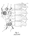
- FIGS. 1 and 2 of the present application A known osteosynthesis device is depicted in U.S. Patent No. 5,108,395 to Jean-Marie Laurain, the disclosure of which is incorporated herein by reference.
- This system is illustrated in FIGS. 1 and 2 of the present application.
- a damaged vertebra V 3 includes a destroyed vertebral body C 3 .
- An interior implant 1 is provided for bridging between the two intact vertebrae V 2 and V 4 to permit removal of the damaged vertebra V 3 and its adjacent disks D 2 and D 3 .
- the anterior implant 1 includes a pair of clamps 2 which are engaged to the intact vertebral bodies by way of a number of spikes 3.
- the implant 1 also includes a plate 6 which is configured to span between the intact vertebrae and is strong enough to support the loads generated in the spinal column at that location.
- Each clamp 2 includes a threaded post 12 projecting therefrom which is configured to pass through a corresponding opening 14 at each end of the plate 6.
- a nut 7 is adapted to engage the threaded post 12 to fix the plate 6 to each of the clamps 2.
- the surface of the clamps 2 include serrations 15 which mate with corresponding serrations 16 at each end of the plate 6, thereby permitting differing angular orientations of the plate relative to each of the clamps.
- An opening 9 is provided through the threaded post 12 of the clamps to receive another bone screw 5 for firm fixation of the clamp with the healthy vertebral bodies V 2 and V 4 .
- the notches are configured to receive the tips of a forceps 19 which is used to provide a distraction force between the two vertebrae V 2 and V 4 .
- the forceps 19 are used to distract and permit room for placement of a bone graft G.
- the anterior plate 6 can be attached to each of the clamps 2 in the manner previously described. Once the plate is in position, the distraction forceps 19 is removed and the nut 7 tightened to form a rigid construct.
- the anterior construct shown in the '395 patent and in FIGS. 1 and 2 of this application is one system for providing anterior fixation with the use of autologous or allogenic bone graft material.
- Other implants have been devised which rely upon an additional element interposed between the adjacent vertebra, in lieu of or in addition to the traditional bone graft material.
- One such device is shown in the patent to Harms et al. no. 4,820,305, which is sold as the "Harms Cage" by the Biedermann-Motech Company.
- This device contemplates a hollow cylindrical mesh which is inserted in the gap between adjacent vertebra, with bone graft material being disposed inside the hollow interior of the mesh.
- the patent to Brantigan, No. 5,192,327 shows a device similar to the "Harms Cage" which is composed of a number of hollow oval-shaped implants within which bone graft material is disposed.
- European Patent No. 0 179 695 to Kehr shows a rigid inert body having a number of passageways extending between the intact vertebrae into which bone growth material can be implanted.
- the device shown in the Kehr European patent includes a plate spanning between the vertebrae having holes for receiving bone screws therethrough.
- Implant devices particularly suited for replacement of vertebral bodies include components of generally solid construction which completely occupy the empty vertebral space. These devices are represented by the patents to Kapp et al., no. 4,554,914; Doty, no. 4,599,086; Ogilvie et al., no. 4,636,217; and Downey, no. 5,147,404. Each of these devices is provided with a spike or similar mechanism for engaging the end plates of the intact vertebrae to maintain the implant in position.
- a similar construction is followed in the U.S. Patent 5,062,850 to MacMillan et al., although this device includes open space between support columns of the axially fixed vertebral body prosthesis.
- the implant device requires separate distraction of the intact vertebrae prior to insertion of the device.
- the following patents show vertebral prosthesis which include some feature for expansion of the device in situ .
- the Main et al., no. 4,932,975, and Barber no. 5,236,460 show prostheses that telescope through the admission of a hydraulic fluid.
- the patents of Rezaian, no. 4,401,112; Wu, no. 4,553,273 and Daher, no. 4,657,550 show devices that expand in situ the manipulation of a threaded component.
- the Rezaian patent shows a turnbuckle construct of this type with the addition of a spiked plate engaged in the opposite intact vertebrae to strengthen the construct.
- vertebral body replacements suffer from one or more disadvantages. For instance, some of the devices do not provide means for osteosynthesis between the intact vertebrae. These devices lack features that can either permit bone ingrowth or facilitate placement of bone graft between adjacent healthy vertebrae. It is recognized that a more permanent and stable correction of a kyphotic condition occurs with fusion of a bony mass in place of the replaced vertebra. Thus, any vertebral body replacement should accommodate this aspect.
- Other vertebral prosthesis offer no means for adjusting the size of the implant to accommodate the specific vertebral anatomy.
- EP-A-567 424 shows an adjustable implant according to the preamble of claim 1
- EP-A-693 274 is prior art within the meaning of Article 54(3) EPC and shows an adjustable implant without and plates. Further, other of the devices do not contemplate some auxiliary fixation to help provide a stable construct. Each of these needs, and many others, are met by the vertebral body replacement according to the present invention.
- the present invention contemplates a vertebral replacement implant and assembly for fixation of the implant in the space left by a removed vertebra between two intact vertebrae.
- the implant includes a thin-walled cylindrical body sized to occupy a substantial portion of the space between the intact vertebrae.
- the cylindrical body is hollow with a plurality of apertures through the wall of the body in communication with the interior, to permit bone ingrowth once the implant is implanted.
- the opposite ends of the cylindrical body carries continuous threads, preferably on the outer surface of the body.
- the inventive implant further contemplates a pair of endplates having a surface directed against a corresponding one of the intact vertebrae when the prosthesis is implanted.
- the endplates each include a cylindrical portion extending from the end surface at a non-perpendicular angle relative to the end surface, which portion includes threads for mating with the threaded ends of the cylindrical body.
- the threads of the endplates are internal to the cylindrical portion.
- the endplates are themselves hollow to provide communication between the hollow interior of the cylindrical body and the adjacent intact vertebrae.
- the invention contemplates the addition of an end cap to the implant to close the end surface of the endplates against the adjacent vertebrae in order to provide additional support for weak vertebrae.
- the means for fixing includes apertures in the threaded portion of the endplates which are threaded to accept a set screw.
- a set screw Preferably, two set screws are threaded into two such apertures in the endplates to apply a clamping pressure against the cylindrical body engaged with the endplate.
- the means for fixing contemplates a crimpable cylindrical portion of the endplates.
- the cylindrical portion includes an annular ring, dissected by a crimping notch. The application of a crimping force around the annular ring reduces the notch, and thereby reduces the circumference of the cylindrical portion so it is tightly engaged about the cylindrical body threaded therein.
- the longitudinal member may be a plate or a rod that is fixed in a known manner to the adjacent intact vertebrae.
- the longitudinal member can be used to assist in the distraction of the intact vertebrae for insertion of the vertebral replacement implant.
- the means for connecting includes a clamp configured to clamp onto the longitudinal member.
- the clamp supports a screw directed towards the replacement implant when it is interposed between the intact vertebrae.
- the cylindrical body of the implant includes a number of apertures threaded to receive the connecting screw.
- the clamp is preferably slidable along the length of the longitudinal implant to facilitate alignment of the screw with the number of threaded apertures of the cylindrical body.
- the clamp includes a spherical seat, and the screw includes a spherical head to permit varying angular orientations of the screw relative to the longitudinal member.
- the means for connecting includes an arm extending from a flange of the endplates.
- the free end of the arm defines an opening through which the longitudinal member extends.
- a set screw intersects the opening to provide fixation of the longitudinal member to the arm of the endplates.
- One object of the present invention is to provide a vertebral body replacement implant configured to support the space left by removal of a damaged or diseased vertebra.
- One objective is to provide an implant that can be easily adjusted to vary the overall length of the implant dependent upon the vertebral level into which the implant is interposed.
- a further objective of the inventive implant is to permit this length adjustment yet provide means for fixing the components to prevent disengagement or unthreading.
- a further object is achieved by the present invention by the provision of means for connecting the vertebral replacement implant to a longitudinal member extending along the length of the spine between the adjacent intact vertebrae.
- the longitudinal member can be used for distracting the space left by the removed vertebra to facilitate insertion of the replacement implant.
- Yet another object is to provide an implant that can house bone growth material to facilitate fusion of the instrumented level.
- vertebral body replacement of the present invention provides a strong implant to support the spinal loads while awaiting fusion of bone growth material between the intact vertebrae.
- a further benefit is that the implant can be more easily adjusted to accommodate spaces at different vertebral levels.
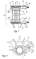
- the assembly 20 generally includes a threaded cylindrical body 21, threaded endplates 22 and end caps 23.
- a set screw 24 is also provided as one embodiment of a means for fixing each of the endplates 22 to a corresponding end of the cylindrical body 21.
- the set screw 24 is a breakable locking screw in which the head of the screw shears off when the tightening torque limit is reached. Such a locking screw is disclosed in co-pending French patent application No. 94 10 377, filed on August 29, 1994.
- the threaded cylindrical body 21 is formed from a cylindrical wall 25 which defines a hollow cavity 26 therein.
- the cavity is configured to receive bone osteosynthesis material, which may be in the form of autogenous or allograph material.
- the cylindrical wall 25 is provided with a plurality of apertures 28 in communication with the cavity 26. These apertures provide a path for bone or tissue ingrowth to further enhance the stability of the implant.
- the cylindrical wall 25 includes a second plurality of threaded apertures 29 generally in the middle of the implant, which are configured to engage the support assembly 55 as described in more detail herein.
- the opposite ends of the cylindrical wall 25 are formed into external threads 32.
- the threads 32 extend from each opposite end over most of the total length of the threaded cylindrical body 21 and are configured to engage the threaded endplates 22.
- Each endplate includes a flange 35, which preferably assumes a shape to cover a substantial load-bearing area of the end plates of the adjacent intact vertebral bodies.
- a cylinder 37 is integrally formed with flange 35 to extend toward the threaded cylindrical body 21 when the endplates 22 are placed within the excised vertebral space.
- the cylinder 37 of each endplate includes a number of threaded openings 39 adapted to receive a set screw 24 therein.
- the cylinder 37 and flange 35 of the endplates 22 define a bore 40 therethrough.
- the inside surface of the bore 40 is provided with internal threads 41 which are configured to mate with the external threads 32 of the cylindrical body 21.
- the threads 41 extend along at least the entire length of the cylinder 37 and preferably into the flange 35.
- FIGS. 4 and 5 Further details of the endplates 22 can be seen in FIGS. 4 and 5.
- the cylinder 37 is integrally formed with the flange 35 to define a lordosis angle 43. This angle is intended to permit use of the vertebral body replacement assembly 20 to replace a damaged vertebra, such as vertebra V 3 shown in FIG. 1, and still maintain the normal lordotic curvature of the spine at that level.
- the end face 36 of the flange 35 is provided with vascularization apertures 45 extending through the flange. These apertures 45 are intended to provide an avenue for vascularization of the space between the adjacent vertebrae.
- the end face 36 can be provided with four spikes, such as spikes 91 shown in the embodiment of FIG. 7. Alternatively, spikes 120 (FIG.
- the spikes (91, 120) are configured to penetrate the end plate of the adjacent vertebra to help maintain the position of the implant in situ.
- the end face is further provided with a mounting slot 47 passing across the flange 35 and spanning along a chord of the internal bore 40. Within each mounting slot is an aperture 48 passing therethrough.
- the cylinder 37 of the endplate 22 is provided with a mounting notch 49 that is aligned with each aperture 48 in the mounting slot 47.
- This slot 47, aperture 48 and notch 49 are configured to support an end cap 23, as herein described.
- the end cap 23 includes a generally rectangular support bar 50 which is mounted to span across a chord of the flat circular plate 52 of the end cap. At each end of the support bar 50 is an outwardly projecting lug 51.
- Each lug 51 is sized to be received within a corresponding aperture 48, while the support bar 50 is itself configured to fit within the mounting slot 47 in the flange 35. Further, each lug 51 slides conveniently into a corresponding mounting notch 49 in the cylinder 37. In this manner, the end cap 23 is held in position, particularly when the replacement body assembly is disposed between the adjacent intact vertebrae V 2 and V 4 .
- the end cap 23 provides additional support for the implant between the adjacent intact vertebrae.
- the end cap can be eliminated if bone growth between the adjacent vertebrae and through the replacement body is preferred.
- the plate 52 of each end cap 23 can be perforated to permit bone ingrowth between the vertebral end plates and the bone growth material disposed within the threaded cylindrical body 21.
- the endplates are shown solid to provide the maximum load bearing capability for loads along the length of the vertebral column.
- the threads 32 on the cylindrical replacement body are external threads, while the threads 40 in the endplates are internal.
- the cylinder 37 of the endplates can carry external threads and the cylindrical replacement body carry internal threads in the cavity 26. In this latter instance, the inner diameter of the cylindrical body would naturally be slightly greater than the outer diameter of the cylinder of the endplates.
- the cylindrical wall forming the implant 21 can be relatively thin, when compared against replacement bodies of the prior art.
- the wall is one (1) mm. thick. Since the primary load endured by the implant will be axial compression, rather than bending, a thin-walled cylinder is appropriate and even desirable.
- the implant 21 include a large number of apertures 28, 29 to promote tissue ingrowth and vascularization, thereby enhancing the stability of the construct after fusion has occurred.
- the total area of the plurality of apertures is at least twenty five percent (25%) of the surface area of the cylindrical body 21.
- the damaged vertebra such as vertebra V 3 shown in FIG. 1
- the clamps 2 of the interior implant 1 shown in FIGS. 1 and 2 are engaged to the intact vertebral bodies in the manner shown in FIG. 2.
- the forceps 19 can be used to distract the intact vertebrae to permit implantation of a vertebral body replacement assembly 20.
- the optimum vertebral height is determined and the threaded cylindrical body 21 and threaded endplates 22 are fitted together to achieve that proper height. Specifically, each of the end caps can be threaded onto the threaded cylindrical body 21 until the desired height is attained.
- the bottom edge 44 of the flange 35 of each of the endplates be generally oriented in the same way between the two threaded endplates 22. This orientation is important because the replacement assembly 20 will be disposed between the two intact vertebrae, bearing against the end plates of those vertebrae.
- the flanges 35, and particularly the end face 36 assume the shape of the vertebral body against which the endplates bear and are sized to occupy as much area of the intact vertebral body end plate as possible.
- the configuration of the flange 35 shown in FIG. 4 is applicable to the thoraco-lumbar vertebrae.
- a smaller, more rounded, configuration can be provided for implantation at the thoracis level, such as the flange 35' shown in FIG. 11.
- the flange 35' is also shown as including a relief radius 38 to increase the clearance between the flange and the dural space housing the spinal cord. This relief radius 38 is preferably included in all three shapes of the endplate flanges.
- the external threads 32 on the threaded cylindrical body 21 are cut in opposite directions so that the endplates can be drawn together or apart by rotating only the cylinder.
- the threads 32 at each of the ends engage the internal threads 41 of each of the end caps 23 in the right direction to draw the end caps together.
- the handedness of the threads 32 can be the same at each end so that it is necessary to individually thread each end cap in opposite directions onto the cylindrical body 21.
- the disadvantage of this arrangement is that it is more difficult to adjust the height of the total assembly 20 while maintaining the proper orientation of each of the lower edges 44 of the end face 36.
- An advantage is that in situ the assembly is unable to unthread itself.
- the set screws 24 are threaded into an appropriate one of the threaded openings 39 in the cylinder 37 of the endplates 22, in order that the set screw 24 extend into contact with the threaded cylindrical body 21.
- the set screws 24 (which can be the breakable locking screws mentioned above) exert a clamping pressure against the body 21 to hold it in place.
- the set screws 24 provide a means for fixing the components together and prevent rotation of the cylindrical body 21 with respect to either of the endplates 22.
- two set screws are used at each endplate 23 to firmly fix the associated ends of the threaded cylindrical body 21.
- the apertures 28 in the threaded body have a smaller diameter than the set screws 24.
- bone graft material can then be inserted into the bore 40 of the endplates and cavity 26 of the cylindrical body 21.
- the endplates 23 are placed in position with the lugs 51 extending through apertures 48, and with support bar 50 passing through mounting slot 47 in each endplate.
- the replacement assembly 20 can then be disposed between the distracted vertebrae V 2 and V 4 .
- a support assembly 55 may be provided.
- this support assembly 55 is configured to mate with the clamps 2 used with the anterior implant system of the prior art shown in FIGS. 1 and 2.
- the support assembly 55 can also be used with other anterior plates, such as the Z-PLATE ATL* sold by Danek Medical, Inc. , or rod systems such as the CD Hopf System of Sofamor, S.N.C.
- the support assembly includes a stabilization plate 57, which can be configured substantially similar to the plate 6 shown in FIG. 1, including the serrations on the bottom face of the ends of the plate.
- Means for connecting the vertebral replacement body assembly 20 to the plate 57 includes a clamp assembly 59 is provided which firmly grips the plate 57 to support a locking screw 69.
- the clamp assembly 59 includes a pair of clamp halves 60 which are preferably in the shape of a C to grip and support the plate 57.
- Each of the clamp halves 60 include an aperture (not shown) which receives a threaded rod 63 of an adjustment plate 62.
- a nut 64 is threaded on the rod 63 to draw the clamp halves 60 together about the stabilization plate 57.
- the adjustment plate 62 includes the threaded rod 63 extending from a face 65 of the plate 62.
- the plate 62 also includes an aperture 67 therethrough having a spherical seat surface 68 into which a corresponding spherical head 70 of the locking screw 69 is received.
- the locking screw 69 includes a hex recess 71 in its head to accept a driving tool.
- the locking screw 69 also includes a threaded shank 73 which is adapted to engage one of the threaded apertures 29 in the threaded cylindrical body 21.
- a guide nub 75 is provided having a smaller diameter than the threaded shank 73.
- the locking screw 69 preferably includes smooth shank 74 between the head 70 of the screw and the threaded shank 73.
- the clamp halves 60 can be tentatively attached but not clamped to the stabilization plate 57.
- the stabilization plate 57 can then be engaged to the clamps 2 in each of the intact vertebral bodies and fixed in place by a corresponding nut, such as nut 7 shown in FIG. 1.
- the distraction forceps 19 can be removed so that the full load of the spinal column can be borne by the replacement assembly 20.
- the clamp halves 60 can be adjusted along the length of the plate 57 so that the locking screw 69 is aligned with an appropriate one of the threaded apertures 29 in the threaded cylindrical body 21.
- the spherical contact between the head 70 of the locking screw 69 and the spherical seat 68 of the adjustment plate 62 allows the locking screw to assume whatever angle is necessary to engage a threaded aperture 29. As so aligned, the locking screw 69 can then be easily threaded into one of the apertures 29 until it is locked between the adjustment plate 62 and the threaded cylindrical body 21. At this point then, the clamp halves 60 can be fully clamped onto the plate 57 by tightening the nut 64 on the threaded rod 63.
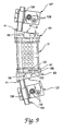
- a vertebral body replacement assembly 80 is configured for connection to an elongated distraction or compression rod.
- the assembly 80 includes opposite endplates 83 which are configured to threadedly engage a cylindrical body 21.
- This cylindrical body 21 is substantially identical in all respects to the cylindrical body 21 described with respect to FIG. 3).
- the endplates 83 include a flange 85 and a cylinder 87 projecting therefrom.
- the cylinder 87 includes a threaded bore 88 which is threaded to accept the external threads 32 of the cylindrical body 21.
- the endplate 83 includes a plurality of vascularization apertures 89 formed through the flange 85.
- the end face 86 of the flange 85 includes a number of spikes 91 projecting therefrom. The spikes are configured to penetrate the end plate of the adjacent vertebral bodies to help maintain the position of the implant in situ .
- the endplates 83 include an arm 94 projecting from the flange 85, which is a component of a means for connecting the implant to a longitudinal member, such as rod 105.
- a rod bore 95 is defined adjacent the free end 94a of the arm 94, with a set screw bore 96 intersecting the rod bore 95 from the free end of the arm 94.
- a set screw 98 is provided which is engaged within the set screw bore 96 to clamp a rod passing therethrough.
- FIGS. 8 and 9 The manner of using the replacement assembly 80 in this embodiment is shown in FIGS. 8 and 9.
- the endplates 83 are engaged in the appropriate vertebrae by way of spikes 91.
- the plates are configured to define an angle 115 to correspond to the proper spinal anatomy at the particular vertebral level.
- a distraction plate 107 is mounted into each of the intact vertebrae by way of bone screw 108.
- the plate 107 includes a collar 109 integrally formed thereon through which a distraction rod 105 passes.
- the distraction rod also extends through each of the rod bores 95 in the arms 94 of the endplates 83.
- the set screws 98 fix the endplates in position. Distraction of the adjacent vertebrae can be achieved by an appropriately formed instrument that can engage the collars 109 of each of the distraction plates 107 mounted into the respective vertebrae.
- a set screw (not shown) can be provided to fix the rod 105 within each collar 109.
- the endplates 83, and particularly the cylinder 87 of the endplates is provided with a means for fixing in the form of a crimping channel 100 around the diameter of the cylinder.
- a crimping notch 101 is provided in the channel 100.
- this crimping notch is a gap in the outer circumference of the channel 100.
- This crimping notch provides a gap which can be closed by an appropriate crimping tool gripping the entire circumference of the crimping channel 100.
Abstract
Description
- The present invention concerns an implant for replacement of one or more vertebral bodies and their adjacent disks. More particularly, the vertebral body replacement is particularly well suited for implantation through an anterior approach.
- The treatment of injuries to the spine has advanced significantly since the days of the first recorded surgical procedure for spinal cord injury in the late 7th Century. The techniques, instrumentation and implants have changed over the years and have been better adapted to address many forms of spinal injury and deformities that can occur due to trauma, disease or congenital effects. One type of spinal deformity, a kyphosis, involves a prolapse of the vertebral column towards the front of the body, often caused by the destruction of the vertebral body itself. This destruction can be in the form of a trauma type injury, such as a fracture or burst injury to the vertebral body, or a non-traumatic deformity caused by a tumor or a degeneration of the bone in the vertebral body.
- Treatment of a kyphosis in the thoracic or lumbar spine appears now to be best achieved through an anterior approach, particularly in order to avoid some of the more severe complications associated with support or replacement of a damaged vertebral body. In most treatments of a kyphosis, a high degree of anterior reconstruction of the spine is required, most frequently involving total removal of the damaged vertebral body. In a typical anterior approach, partial or total ablation of the vertebral body and the two adjacent vertebral disks is carried out. The remaining space is then distracted to manipulate the spine to its correct orientation.
- In many cases, the space is filled with a polymerizable paste or a bone graft which is frequently modeled to give it the shape of the destroyed vertebral body. Frequently, autologous bone, such as that extracted from the ilium, is used to bridge the space. The polymerizable paste can include a PMMA bone cement. Once the cavity remaining after the removal of the original vertebral body has been filled, an osteosynthesis instrument is positioned between the adjacent unaffected vertebrae to prevent any relative movement therebetween. The osteosynthesis device is essential to restabilize the vertebral column, to support the loads to which the thoracic or lumbar spine is exposed, and to enhance the likelihood and quickness of union of the bone graft material with the adjacent vertebral bodies. Once the bone graft and material is sufficiently solid, the osteosynthesis device normally is not subjected to any further mechanical stresses.
- A known osteosynthesis device is depicted in U.S. Patent No. 5,108,395 to Jean-Marie Laurain, the disclosure of which is incorporated herein by reference. This system is illustrated in FIGS. 1 and 2 of the present application. Referring first to FIG. 1, it can be seen that a damaged vertebra V3 includes a destroyed vertebral body C3. An
interior implant 1 is provided for bridging between the two intact vertebrae V2 and V4 to permit removal of the damaged vertebra V3 and its adjacent disks D2 and D3. Theanterior implant 1 includes a pair ofclamps 2 which are engaged to the intact vertebral bodies by way of a number ofspikes 3. In addition, theclamps 2 are maintained in position bybone screws 5 extending throughscrew holes 11,lateral lugs 8 of the clamps. Theimplant 1 also includes a plate 6 which is configured to span between the intact vertebrae and is strong enough to support the loads generated in the spinal column at that location. - Each
clamp 2 includes a threadedpost 12 projecting therefrom which is configured to pass through acorresponding opening 14 at each end of the plate 6. Anut 7 is adapted to engage the threadedpost 12 to fix the plate 6 to each of theclamps 2. The surface of theclamps 2 includeserrations 15 which mate withcorresponding serrations 16 at each end of the plate 6, thereby permitting differing angular orientations of the plate relative to each of the clamps. An opening 9 is provided through the threadedpost 12 of the clamps to receive anotherbone screw 5 for firm fixation of the clamp with the healthy vertebral bodies V2 and V4. - An important feature of the system described in the '395 patent is the provision of
notches 18 in each of theclamps 2. The notches are configured to receive the tips of aforceps 19 which is used to provide a distraction force between the two vertebrae V2 and V4. As shown in FIG. 2, once theclamps 2 are fixed to the corresponding intact vettebrae, theforceps 19 are used to distract and permit room for placement of a bone graft G. Once the bone graft is in place, the anterior plate 6 can be attached to each of theclamps 2 in the manner previously described. Once the plate is in position, thedistraction forceps 19 is removed and thenut 7 tightened to form a rigid construct. - The anterior construct shown in the '395 patent and in FIGS. 1 and 2 of this application is one system for providing anterior fixation with the use of autologous or allogenic bone graft material. Other implants have been devised which rely upon an additional element interposed between the adjacent vertebra, in lieu of or in addition to the traditional bone graft material. One such device is shown in the patent to Harms et al. no. 4,820,305, which is sold as the "Harms Cage" by the Biedermann-Motech Company. This device contemplates a hollow cylindrical mesh which is inserted in the gap between adjacent vertebra, with bone graft material being disposed inside the hollow interior of the mesh.
- The patent to Brantigan, No. 5,192,327, shows a device similar to the "Harms Cage" which is composed of a number of hollow oval-shaped implants within which bone graft material is disposed. European Patent No. 0 179 695 to Kehr shows a rigid inert body having a number of passageways extending between the intact vertebrae into which bone growth material can be implanted. In addition, the device shown in the Kehr European patent includes a plate spanning between the vertebrae having holes for receiving bone screws therethrough.
- Another variety of implant devices particularly suited for replacement of vertebral bodies include components of generally solid construction which completely occupy the empty vertebral space. These devices are represented by the patents to Kapp et al., no. 4,554,914; Doty, no. 4,599,086; Ogilvie et al., no. 4,636,217; and Downey, no. 5,147,404. Each of these devices is provided with a spike or similar mechanism for engaging the end plates of the intact vertebrae to maintain the implant in position. A similar construction is followed in the U.S. Patent 5,062,850 to MacMillan et al., although this device includes open space between support columns of the axially fixed vertebral body prosthesis.
- In each of the former patents, the implant device requires separate distraction of the intact vertebrae prior to insertion of the device. The following patents show vertebral prosthesis which include some feature for expansion of the device in situ. For example, the Main et al., no. 4,932,975, and Barber no. 5,236,460 show prostheses that telescope through the admission of a hydraulic fluid. The patents of Rezaian, no. 4,401,112; Wu, no. 4,553,273 and Daher, no. 4,657,550 show devices that expand in situ the manipulation of a threaded component. In addition, the Rezaian patent shows a turnbuckle construct of this type with the addition of a spiked plate engaged in the opposite intact vertebrae to strengthen the construct.
- In recent years, the application of anterior approaches to instrumenting the spine has become more prevalent. As these anterior approaches advance, it becomes of greater necessity to provide a vertebral body replacement that meets all of the benefits of anterior surgery without the detriments of the several prior devices. Each of the above-mentioned vertebral body replacements suffer from one or more disadvantages. For instance, some of the devices do not provide means for osteosynthesis between the intact vertebrae. These devices lack features that can either permit bone ingrowth or facilitate placement of bone graft between adjacent healthy vertebrae. It is recognized that a more permanent and stable correction of a kyphotic condition occurs with fusion of a bony mass in place of the replaced vertebra. Thus, any vertebral body replacement should accommodate this aspect. Other vertebral prosthesis offer no means for adjusting the size of the implant to accommodate the specific vertebral anatomy.
- EP-A-567 424 shows an adjustable implant according to the preamble of
claim 1 - EP-A-693 274 is prior art within the meaning of Article 54(3) EPC and shows an adjustable implant without and plates. Further, other of the devices do not contemplate some auxiliary fixation to help provide a stable construct. Each of these needs, and many others, are met by the vertebral body replacement according to the present invention.
- The present invention contemplates a vertebral replacement implant and assembly for fixation of the implant in the space left by a removed vertebra between two intact vertebrae. In one aspect, the implant includes a thin-walled cylindrical body sized to occupy a substantial portion of the space between the intact vertebrae. The cylindrical body is hollow with a plurality of apertures through the wall of the body in communication with the interior, to permit bone ingrowth once the implant is implanted. The opposite ends of the cylindrical body carries continuous threads, preferably on the outer surface of the body.
- The inventive implant further contemplates a pair of endplates having a surface directed against a corresponding one of the intact vertebrae when the prosthesis is implanted. The endplates each include a cylindrical portion extending from the end surface at a non-perpendicular angle relative to the end surface, which portion includes threads for mating with the threaded ends of the cylindrical body. Preferably, the threads of the endplates are internal to the cylindrical portion. In one aspect, the endplates are themselves hollow to provide communication between the hollow interior of the cylindrical body and the adjacent intact vertebrae. Alternatively, the invention contemplates the addition of an end cap to the implant to close the end surface of the endplates against the adjacent vertebrae in order to provide additional support for weak vertebrae.
- Another feature of the invention resides in the provision of means for fixing the cylindrical body to each of the endplates to prevent unthreading of the mating threads of the three components of the implant. In one embodiment, the means for fixing includes apertures in the threaded portion of the endplates which are threaded to accept a set screw. Preferably, two set screws are threaded into two such apertures in the endplates to apply a clamping pressure against the cylindrical body engaged with the endplate.
- In another embodiment, the means for fixing contemplates a crimpable cylindrical portion of the endplates. In one aspect, the cylindrical portion includes an annular ring, dissected by a crimping notch. The application of a crimping force around the annular ring reduces the notch, and thereby reduces the circumference of the cylindrical portion so it is tightly engaged about the cylindrical body threaded therein.
- Another inventive aspect resides in the provision of means for connecting the implant to a longitudinal member extending outside the space left by the removed vertebrae. The longitudinal member may be a plate or a rod that is fixed in a known manner to the adjacent intact vertebrae. Preferably, the longitudinal member can be used to assist in the distraction of the intact vertebrae for insertion of the vertebral replacement implant.
- In one embodiment, the means for connecting includes a clamp configured to clamp onto the longitudinal member. The clamp supports a screw directed towards the replacement implant when it is interposed between the intact vertebrae. The cylindrical body of the implant includes a number of apertures threaded to receive the connecting screw. The clamp is preferably slidable along the length of the longitudinal implant to facilitate alignment of the screw with the number of threaded apertures of the cylindrical body. In addition, the clamp includes a spherical seat, and the screw includes a spherical head to permit varying angular orientations of the screw relative to the longitudinal member.
- In another embodiment, the means for connecting includes an arm extending from a flange of the endplates. The free end of the arm defines an opening through which the longitudinal member extends. A set screw intersects the opening to provide fixation of the longitudinal member to the arm of the endplates.
- One object of the present invention is to provide a vertebral body replacement implant configured to support the space left by removal of a damaged or diseased vertebra. One objective is to provide an implant that can be easily adjusted to vary the overall length of the implant dependent upon the vertebral level into which the implant is interposed. A further objective of the inventive implant is to permit this length adjustment yet provide means for fixing the components to prevent disengagement or unthreading.
- A further object is achieved by the present invention by the provision of means for connecting the vertebral replacement implant to a longitudinal member extending along the length of the spine between the adjacent intact vertebrae. The longitudinal member can be used for distracting the space left by the removed vertebra to facilitate insertion of the replacement implant. Yet another object is to provide an implant that can house bone growth material to facilitate fusion of the instrumented level.
- One benefit of the vertebral body replacement of the present invention is that it provides a strong implant to support the spinal loads while awaiting fusion of bone growth material between the intact vertebrae. A further benefit is that the implant can be more easily adjusted to accommodate spaces at different vertebral levels.
- Other objects and benefits of the invention can be gleaned from the following written description of the invention, considered together with the accompanying figures and claims.
-
- FIG. 1 is an exploded perspective view of a spinal osteosynthesis implant according to the prior art patent 5,108,395.
- FIG. 2 is a view showing a portion of the view of FIG. 1 with the addition of an instrument for permitting positioning of a graft between the vertebrae carrying the clamps associated with the prior device of the '395 patent.
- FIG. 3 is an exploded perspective view of a vertebral body replacement assembly in accordance with one embodiment of the present invention.
- FIG. 4 is an end elevational view of an endplate used in connection with the vertebral body replacement assembly shown in FIG. 3.
- FIG. 5 is a side elevational view of an endplate used with the vertebral body replacement assembly of FIG. 3.
- FIG. 6 is a perspective exploded view showing a component of the clamp assembly used with the vertebral body replacement assembly shown in FIG. 3.
- FIG. 7 is a side elevational view of a vertebral body replacement assembly in accordance with another embodiment of the invention, particularly for use with an elongated rod spanning the vertebral sections.
- FIG. 8 is an end elevational view of the vertebral body replacement assembly shown in FIG. 7, with the assembly shown in position on a intact vertebra.
- FIG. 9 is a side elevational view of the assembly shown in FIG. 7 as engaged to an elongated rod.
- FIG. 10 is a perspective view of the endplate used with the vertebral body replacement assembly shown in FIG. 7.
- FIG. 11 is an end elevational view of one specific endplate used in connection with the vertebral body replacement assembly shown in FIG. 3 in the thoracic spine.
-
- For the purposes of promoting an understanding of the principles of the invention, reference will now be made to the embodiments illustrated in the drawings and specific language will be used to describe the same. It will nevertheless be understood that no limitation of the scope of the invention is thereby intended, such alterations and further modifications in the illustrated device, and such further applications of the principles of the invention as illustrated therein being contemplated as would normally occur to one skilled in the art to which the invention relates.
- Referring now to FIG. 3, a vertebral
body replacement assembly 20 is shown in accordance with one embodiment of the present invention. Theassembly 20 generally includes a threadedcylindrical body 21, threadedendplates 22 andend caps 23. Aset screw 24 is also provided as one embodiment of a means for fixing each of theendplates 22 to a corresponding end of thecylindrical body 21. In one specific embodiment, theset screw 24 is a breakable locking screw in which the head of the screw shears off when the tightening torque limit is reached. Such a locking screw is disclosed in co-pending French patent application No. 94 10 377, filed on August 29, 1994. - The threaded
cylindrical body 21 is formed from acylindrical wall 25 which defines ahollow cavity 26 therein. The cavity is configured to receive bone osteosynthesis material, which may be in the form of autogenous or allograph material. Thecylindrical wall 25 is provided with a plurality ofapertures 28 in communication with thecavity 26. These apertures provide a path for bone or tissue ingrowth to further enhance the stability of the implant. Thecylindrical wall 25 includes a second plurality of threadedapertures 29 generally in the middle of the implant, which are configured to engage thesupport assembly 55 as described in more detail herein. - In one important feature of the
cylindrical body 21, the opposite ends of thecylindrical wall 25 are formed intoexternal threads 32. In one specific embodiment, thethreads 32 extend from each opposite end over most of the total length of the threadedcylindrical body 21 and are configured to engage the threadedendplates 22. Each endplate includes aflange 35, which preferably assumes a shape to cover a substantial load-bearing area of the end plates of the adjacent intact vertebral bodies. Acylinder 37 is integrally formed withflange 35 to extend toward the threadedcylindrical body 21 when theendplates 22 are placed within the excised vertebral space. Thecylinder 37 of each endplate includes a number of threadedopenings 39 adapted to receive aset screw 24 therein. - The
cylinder 37 andflange 35 of theendplates 22 define abore 40 therethrough. The inside surface of thebore 40 is provided withinternal threads 41 which are configured to mate with theexternal threads 32 of thecylindrical body 21. In the preferred embodiment, thethreads 41 extend along at least the entire length of thecylinder 37 and preferably into theflange 35. - Further details of the
endplates 22 can be seen in FIGS. 4 and 5. As shown in FIG. 5, thecylinder 37 is integrally formed with theflange 35 to define alordosis angle 43. This angle is intended to permit use of the vertebralbody replacement assembly 20 to replace a damaged vertebra, such as vertebra V3 shown in FIG. 1, and still maintain the normal lordotic curvature of the spine at that level. The end face 36 of theflange 35 is provided withvascularization apertures 45 extending through the flange. Theseapertures 45 are intended to provide an avenue for vascularization of the space between the adjacent vertebrae. The end face 36 can be provided with four spikes, such asspikes 91 shown in the embodiment of FIG. 7. Alternatively, spikes 120 (FIG. 3) can be provided that include a threadedstem 121 to be engaged in threadedapertures 46 defined inend face 36. In either case, the spikes (91, 120) are configured to penetrate the end plate of the adjacent vertebra to help maintain the position of the implant in situ. - The end face is further provided with a mounting
slot 47 passing across theflange 35 and spanning along a chord of theinternal bore 40. Within each mounting slot is anaperture 48 passing therethrough. Thecylinder 37 of theendplate 22 is provided with a mountingnotch 49 that is aligned with eachaperture 48 in the mountingslot 47. Thisslot 47,aperture 48 and notch 49 are configured to support anend cap 23, as herein described. Referring back to FIG. 3, theend cap 23 includes a generallyrectangular support bar 50 which is mounted to span across a chord of the flatcircular plate 52 of the end cap. At each end of thesupport bar 50 is an outwardly projectinglug 51. Eachlug 51 is sized to be received within a correspondingaperture 48, while thesupport bar 50 is itself configured to fit within the mountingslot 47 in theflange 35. Further, eachlug 51 slides conveniently into a corresponding mountingnotch 49 in thecylinder 37. In this manner, theend cap 23 is held in position, particularly when the replacement body assembly is disposed between the adjacent intact vertebrae V2 and V4. - The
end cap 23 provides additional support for the implant between the adjacent intact vertebrae. The end cap can be eliminated if bone growth between the adjacent vertebrae and through the replacement body is preferred. Alternatively, theplate 52 of eachend cap 23 can be perforated to permit bone ingrowth between the vertebral end plates and the bone growth material disposed within the threadedcylindrical body 21. In the preferred embodiment, the endplates are shown solid to provide the maximum load bearing capability for loads along the length of the vertebral column. - In the illustrated embodiment, the
threads 32 on the cylindrical replacement body are external threads, while thethreads 40 in the endplates are internal. Alternatively, thecylinder 37 of the endplates can carry external threads and the cylindrical replacement body carry internal threads in thecavity 26. In this latter instance, the inner diameter of the cylindrical body would naturally be slightly greater than the outer diameter of the cylinder of the endplates. - In the preferred embodiment, the cylindrical wall forming the
implant 21 can be relatively thin, when compared against replacement bodies of the prior art. In one specific embodiment, the wall is one (1) mm. thick. Since the primary load endured by the implant will be axial compression, rather than bending, a thin-walled cylinder is appropriate and even desirable. - It is also preferred that the
implant 21 include a large number ofapertures cylindrical body 21. - In use, the damaged vertebra, such as vertebra V3 shown in FIG. 1, is removed. In one embodiment, the
clamps 2 of theinterior implant 1 shown in FIGS. 1 and 2 are engaged to the intact vertebral bodies in the manner shown in FIG. 2. Also shown in FIG. 2, theforceps 19 can be used to distract the intact vertebrae to permit implantation of a vertebralbody replacement assembly 20. In the preferred method, the optimum vertebral height is determined and the threadedcylindrical body 21 and threadedendplates 22 are fitted together to achieve that proper height. Specifically, each of the end caps can be threaded onto the threadedcylindrical body 21 until the desired height is attained. - It is important that the
bottom edge 44 of theflange 35 of each of the endplates be generally oriented in the same way between the two threadedendplates 22. This orientation is important because thereplacement assembly 20 will be disposed between the two intact vertebrae, bearing against the end plates of those vertebrae. In order to maintain the maximum load bearing capability, theflanges 35, and particularly theend face 36, assume the shape of the vertebral body against which the endplates bear and are sized to occupy as much area of the intact vertebral body end plate as possible. - Preferably, three such shapes are provided to accommodate the anatomic variations of the vertebral bodies at the lumbar, thoraco-lumbar and thoracic levels. the configuration of the
flange 35 shown in FIG. 4 is applicable to the thoraco-lumbar vertebrae. A smaller, more rounded, configuration can be provided for implantation at the thoracis level, such as the flange 35' shown in FIG. 11. The flange 35' is also shown as including arelief radius 38 to increase the clearance between the flange and the dural space housing the spinal cord. Thisrelief radius 38 is preferably included in all three shapes of the endplate flanges. - In one specific embodiment, the
external threads 32 on the threadedcylindrical body 21 are cut in opposite directions so that the endplates can be drawn together or apart by rotating only the cylinder. Thus, as the cylinder is rotated in one direction, thethreads 32 at each of the ends engage theinternal threads 41 of each of the end caps 23 in the right direction to draw the end caps together. Alternatively, the handedness of thethreads 32 can be the same at each end so that it is necessary to individually thread each end cap in opposite directions onto thecylindrical body 21. The disadvantage of this arrangement is that it is more difficult to adjust the height of thetotal assembly 20 while maintaining the proper orientation of each of thelower edges 44 of theend face 36. An advantage is that in situ the assembly is unable to unthread itself. - Once the endplates and threaded cylindrical body have been engaged in the proper orientation for the correct height, the
set screws 24 are threaded into an appropriate one of the threadedopenings 39 in thecylinder 37 of theendplates 22, in order that theset screw 24 extend into contact with the threadedcylindrical body 21. The set screws 24 (which can be the breakable locking screws mentioned above) exert a clamping pressure against thebody 21 to hold it in place. Thus, theset screws 24 provide a means for fixing the components together and prevent rotation of thecylindrical body 21 with respect to either of theendplates 22. Preferably, two set screws are used at eachendplate 23 to firmly fix the associated ends of the threadedcylindrical body 21. To ensure that theset screws 24 achieve firm purchase on thebody 21, theapertures 28 in the threaded body have a smaller diameter than the set screws 24. - With the cylinder and endplates thus fixed at their proper height dimension, bone graft material can then be inserted into the
bore 40 of the endplates andcavity 26 of thecylindrical body 21. After the interior of these components has been completely filled with bone graft material, theendplates 23 are placed in position with thelugs 51 extending throughapertures 48, and withsupport bar 50 passing through mountingslot 47 in each endplate. Thereplacement assembly 20 can then be disposed between the distracted vertebrae V2 and V4. Once the assembly is properly positioned with the end faces 36 of each of theendplates 22 properly oriented on the vertebral end plates, thedistraction forceps 19 are removed so that theassembly 20 is clamped in place between the two vertebrae. - In order to further ensure that the
replacement assembly 20 will not migrate or slip in its position between the intact vertebrae, asupport assembly 55 may be provided. In the preferred embodiment, thissupport assembly 55 is configured to mate with theclamps 2 used with the anterior implant system of the prior art shown in FIGS. 1 and 2. Thesupport assembly 55 can also be used with other anterior plates, such as the Z-PLATE ATL* sold by Danek Medical, Inc. , or rod systems such as the CD Hopf System of Sofamor, S.N.C. - In particular, the support assembly includes a
stabilization plate 57, which can be configured substantially similar to the plate 6 shown in FIG. 1, including the serrations on the bottom face of the ends of the plate. Means for connecting the vertebralreplacement body assembly 20 to theplate 57 includes aclamp assembly 59 is provided which firmly grips theplate 57 to support a lockingscrew 69. Theclamp assembly 59 includes a pair of clamp halves 60 which are preferably in the shape of a C to grip and support theplate 57. Each of the clamp halves 60 include an aperture (not shown) which receives a threadedrod 63 of anadjustment plate 62. Anut 64 is threaded on therod 63 to draw the clamp halves 60 together about thestabilization plate 57. - The details of the
adjustment plate 62 are shown more clearly in FIG. 6. The adjustment plate includes the threadedrod 63 extending from aface 65 of theplate 62. Theplate 62 also includes anaperture 67 therethrough having aspherical seat surface 68 into which a correspondingspherical head 70 of the lockingscrew 69 is received. The lockingscrew 69 includes ahex recess 71 in its head to accept a driving tool. The lockingscrew 69 also includes a threadedshank 73 which is adapted to engage one of the threadedapertures 29 in the threadedcylindrical body 21. To help guide the lockingscrew 69 into position, aguide nub 75 is provided having a smaller diameter than the threadedshank 73. The lockingscrew 69 preferably includessmooth shank 74 between thehead 70 of the screw and the threadedshank 73. - In use, the clamp halves 60 can be tentatively attached but not clamped to the
stabilization plate 57. Thestabilization plate 57 can then be engaged to theclamps 2 in each of the intact vertebral bodies and fixed in place by a corresponding nut, such asnut 7 shown in FIG. 1. With thestabilization plate 57 thus attached between the distracted vertebrae, thedistraction forceps 19 can be removed so that the full load of the spinal column can be borne by thereplacement assembly 20. Once the distraction forceps have been removed, the clamp halves 60 can be adjusted along the length of theplate 57 so that the lockingscrew 69 is aligned with an appropriate one of the threadedapertures 29 in the threadedcylindrical body 21. The spherical contact between thehead 70 of the lockingscrew 69 and thespherical seat 68 of theadjustment plate 62 allows the locking screw to assume whatever angle is necessary to engage a threadedaperture 29. As so aligned, the lockingscrew 69 can then be easily threaded into one of theapertures 29 until it is locked between theadjustment plate 62 and the threadedcylindrical body 21. At this point then, the clamp halves 60 can be fully clamped onto theplate 57 by tightening thenut 64 on the threadedrod 63. - In another embodiment of the invention, a vertebral
body replacement assembly 80 is configured for connection to an elongated distraction or compression rod. In this embodiment, theassembly 80 includesopposite endplates 83 which are configured to threadedly engage acylindrical body 21. (Thiscylindrical body 21 is substantially identical in all respects to thecylindrical body 21 described with respect to FIG. 3). With this embodiment, theendplates 83 include aflange 85 and acylinder 87 projecting therefrom. Thecylinder 87 includes a threadedbore 88 which is threaded to accept theexternal threads 32 of thecylindrical body 21. Like the prior endplates, theendplate 83 includes a plurality ofvascularization apertures 89 formed through theflange 85. The end face 86 of theflange 85 includes a number ofspikes 91 projecting therefrom. The spikes are configured to penetrate the end plate of the adjacent vertebral bodies to help maintain the position of the implant in situ. - As shown in FIGS. 7 and 8, the
endplates 83 include anarm 94 projecting from theflange 85, which is a component of a means for connecting the implant to a longitudinal member, such asrod 105. A rod bore 95 is defined adjacent the free end 94a of thearm 94, with a set screw bore 96 intersecting the rod bore 95 from the free end of thearm 94. Aset screw 98 is provided which is engaged within the set screw bore 96 to clamp a rod passing therethrough. - The manner of using the
replacement assembly 80 in this embodiment is shown in FIGS. 8 and 9. In particular, theendplates 83 are engaged in the appropriate vertebrae by way of spikes 91. Again, the plates are configured to define anangle 115 to correspond to the proper spinal anatomy at the particular vertebral level. Adistraction plate 107 is mounted into each of the intact vertebrae by way ofbone screw 108. Theplate 107 includes acollar 109 integrally formed thereon through which adistraction rod 105 passes. The distraction rod also extends through each of the rod bores 95 in thearms 94 of theendplates 83. With the rod extending through each of the bores, theset screws 98 fix the endplates in position. Distraction of the adjacent vertebrae can be achieved by an appropriately formed instrument that can engage thecollars 109 of each of thedistraction plates 107 mounted into the respective vertebrae. A set screw (not shown) can be provided to fix therod 105 within eachcollar 109. - Referring to FIGS. 7, 9 and 10, details of the manner in which the endplates are fixed to the threaded cylindrical body is described. In particular, the
endplates 83, and particularly thecylinder 87 of the endplates, is provided with a means for fixing in the form of a crimpingchannel 100 around the diameter of the cylinder. At opposite sides of the cylinder, a crimpingnotch 101 is provided in thechannel 100. In essence, this crimping notch is a gap in the outer circumference of thechannel 100. This crimping notch provides a gap which can be closed by an appropriate crimping tool gripping the entire circumference of the crimpingchannel 100. As the crimping tool is tightened, thenotches 101 close as the channel moves together in the direction of thearrows 102. It can be seen that this crimping aspect will replace theset screw 24 disclosed with the previous embodiment for fixing the endplates to the threaded cylindrical body. - While the invention has been illustrated and described in detail in the drawings and foregoing description, the same is to be considered as illustrative and not restrictive in character, it being understood that only the preferred embodiments have been shown and described and that all changes and modifications that come within the scope of the invention as set out in the claims are desired to be protected.
Claims (35)
- A vertebral replacement implant (20) for interposition in a space left by one or more removed vertebrae between adjacent intact vertebrae, comprising:characterized in that said cylindrical portion integrally extends from said endplate at a non-perpendicular angle relative to said end surface, said non-perpendicular angle corresponding to the curvature of the spine at the space between the intact vertebrae.a replacement body (21) with opposite ends sized to span a portion of the space between the intact vertebrae, said replacement body having first threads defined thereon at each of said opposite ends; anda pair of endplates (22) each having an end surface (23) for contacting a respective one of the intact vertebrae when the implant is interposed in the space between the intact vertebrae, each of said endplates including a cylindrical portion having second threads defined thereon configured to threadedly engage said first threads on said replacement body; and
- The vertebral replacement implant (20) according to claim 1, wherein said replacement body (21) includes a cylindrical wall (25) defining a hollow interior (26), said cylindrical wall (25) defining a plurality of apertures (28) therethrough, said apertures (28) being in communication with said hollow interior (26) of said replacement body (21) to facilitate tissue ingrowth into said replacement body (21).
- The vertebral replacement body (21) according to claim 2, wherein said cylindrical wall (25) defining said replacement body (21) has a surface area and said plurality of apertures (28) define an effective area greater than twenty five percent (25%) of said surface area.
- The vertebral replacement implant (20) according to claim 2 or 3, wherein the hollow interior (26) of said replacement body (21) is open at said opposite ends.
- The vertebral replacement implant (20) according to one of claims 1 to 4, wherein said replacement body (21) includes a cylindrical wall (25) defining a hollow interior (26) and is open at said opposite ends.
- The vertebral replacement implant according to claim 5, wherein each of said endplates (22) defines a bore (40) therethrough opening at said end surface and at said cylindrical portion (37).
- The vertebral replacement implant (20) according to claim 6, wherein said first threads on said replacement body (21) are external threads (32) and said second threads on said cylindrical portion (37) of said pair of endplates are internal threads (41).
- The vertebral replacement implant (20) according to claim 6 or 7, further comprising an end cap (23) for closing said bore (40) of one of said endplates at said end surface thereof, said end cap (23) having means for supporting said end cap (23) on said endplate (22).
- The vertebral replacement implant (20) according to one of claims 1 to 8, wherein said first threads on said replacement body (21) are external threads (32) and said second threads on said cylindrical portion (37) of said pair of endplates (22) are internal threads (41).
- The vertebral replacement implant (20) according to one of claims 1 to 9, further comprising means for fixing said replacement body (21) to each of said endplates (22) to prevent unthreading of said first and second threads.
- The vertebral replacement implant (20) according to claim 10, wherein said means for fixing includes:a number of openings (39) defined in said cylindrical portion (37) of each of said pair of endplates; anda member (24) extendable through one of said number of openings and into contact with said replacement body (21).
- The vertebral replacement (20) implant according to claim 11, wherein:said member is a set screw (24); andsaid number of openings (29) are threaded to receive said set screw in threaded engagement.
- The vertebral replacement implant (20) according to claim 11 or 12, wherein said number of openings (29) are defined in said endplates (22) at said second threads (41).
- The vertebral replacement implant (20) according to one of claims 1 to 13, wherein each of said endplates (22) includes a flange (35) defining said end surface, said flange (35) extending radially outwardly from said cylindrical portion (37) and defining a shape generally corresponding to the shape of a portion of the intact vertebra against which the endplate (22) is in contact.
- The vertebral replacement implant (20) according to claim 14, wherein said flange (35) defines a number of vascularization apertures (45) therethrough.
- The vertebral replacement implant (20) according to one ofclaims 1 to 15, wherein each of said endplates (22) defines a bore (40) therethrough opening at said end surface and at said cylindrical portion; and
further comprising an end cap (23) for closing said bore of one of said endplates at said end surface thereof, said end cap (23) including:wherein said endplate (22) includes a slot (47) defined at said end surface for receiving said support bar (50) so that said plate (52) of said end cap (23) resides flush with said end surface of said endplate (22).a plate shaped (52) to correspond to said bore opening in said endplate (22); anda support bar (50) attached to said plate; and - The vertebral replacement implant (20) according to one of claims 10 to 16, wherein said cylindrical portion (37) of each of said endplates (22) has a length; and
said means for fixing includes a crimping notch (101) formed along a portion of said length of said cylindrical portion (37), said cylindrical portion being deformable at said crimping notch to close said notch and thereby reduce the circumference of said cylindrical portion (37) about said replacement body (21) when said replacement body (21) is threadedly engaged to said endplate cylindrical portion (37). - The vertebral replacement implant (20) according to one of claims 1 to 17, wherein each of said pair of endplates (22) includes a number of spikes (91) projecting from said end surface (36) for implantation in a corresponding one of the adjacent intact vertebrae.
- The vertebral replacement implant (20) according to claim 18, wherein:said end surface (36) of each of said pair of endplates (22) defines a number of threaded apertures (46) therein; andeach of said number of spikes (120) includes a threaded post (121) configured for engagement with said threaded apertures (46) in said end surface (36) of each of said endplates (22).
- The vertebral replacement implant (20) according to one of claims 1 to 19, wherein each of said endplates (22) defines a bore (40) therethrough opening at said end surface (36) and at said cylindrical portion (37).
- The vertebral replacement implant (20) according to one of claims 1 to 20, wherein each of said endplates (22) includes a flange (35) defining said end surface (36) and extending outwardly from said cylindrical portion (37), said flange (35) including an arm (94) projecting away from said cylindrical portion (37), said arm (94) having a free end configured to extend beyond the adjacent intact vertebrae for engagement to a longitudinal member (105) disposed along the length of the spinal column.
- The vertebral replacement implant (20) according to claim 21, wherein said arm (94) defines a bore (95) at said free end for receiving the longitudinal member (105) therethrough.
- The vertebral replacement implant (20) according to one of claims to 22, wherein engagement between said second threads (41) on each of said endplates with said first threads (32) on said replacement body (21) allows for said endplates (22) to be variably positioned along the length of said replacement body.
- The vertebral replacement implant (20) according to one of claims 1 to 23, further comprising means for fixing said replacement body (21) to each of said endplates (22) to prevent disengagement therebetween.
- The vertebral replacement implant (20) according to one of claims 1 to 24, wherein said replacement body (21) comprises a thin-walled cylindrical body (25) defining a hollow interior (26) and having an outer surface defining a plurality of apertures (28) having a combined area at least equal to twenty-five percent (25%) of the outer surface area.
- The vertebral replacement implant (20) according to one of claims 1 to 25, wherein:said cylindrical portion (37) of each of said endplates (22) has a length; andsaid cylindrical portion defines a crimping notch (101) formed along a portion of said length of said cylindrical portion, said cylindrical portion (37) being deformable at said crimping notch (101) to close said notch (101) and thereby reduce the circumference of said cylindrical portion (37) about said replacement body (21) when said replacement body (21) is threadedly engaged to said cylindrical portion (37).
- The vertebral replacement implant (20) according to one of claims 2 to 26, wherein at least some of said plurality of apertures (28) extend through said first threads (32) of said replacement body (21).
- The vertebral replacement implant (20) according to one of claims 7 to 27, wherein said replacement body (21) includes a cylindrical (25) wall defining a hollow interior (26), said cylindrical wall (25) defining a plurality of apertures (28) therethrough, said apertures being in communication with said hollow interior (26) of said replacement body to facilitate tissue ingrowth into said replacement body.
- The vertebral replacement implant (20) according to claim 28, wherein at least some of said plurality of apertures (28) extend through said external threads (32) of said replacement body (21).
- An assembly for fixation of adjacent intact vertebrae following removal of an intermediate damaged vertebra, comprising:the vertebral replacement implant (20) according to one of claims 1 to 29 interposed in a space between the adjacent intact vertebrae; andan elongated longitudinal member (105) sized to span between and fixedly engage the adjacent intact vertebrae outside the space between the adjacent intact vertebrae.
- The assembly for fixation of adjacent intact vertebrae according to claim 30, further comprising means for connecting said vertebral replacement implant to said elongated longitudinal member.
- The assembly for fixation of adjacent intact vertebrae according to claim 31, wherein said replacement body (20) defines a number of threaded openings; and
said means for connecting includes:a clamp for clamping said longitudinal member; anda screw attached to said clamp, said screw having threads for engaging one of said number of threaded openings and having a length sufficient for said screw to engage said replacement body when said clamp is engaged to said longitudinal member. - The assembly for fixation of adjacent intact vertebrae according to claim 32, wherein:said clamp includes a plate, said plate defining an aperture having a spherical seat; andsaid screw includes a spherical head configured for engagement within said spherical seat.
- The assembly for fixation of adjacent intact vertebrae according to claims one of 30 to 33, wherein each of said endplates (83) includes a flange defining said end surface and extending outwardly from said cylindrical portion; and
said means for connecting includes an arm integral (94) with said flange (93) and projecting away from said cylindrical portion, said arm (94) having a free end configured to extend beyond the adjacent intact vertebrae for engagement to the longitudinal member (105). - The assembly for fixation of adjacent intact vertebrae according to claim 34, wherein said arm (94) defines a first bore (95) at said free end for receiving the longitudinal member (105) therethrough and a set screw bore (96) at said free end intersecting said first bore; and
said means for connecting includes a set screw (98) for threading into said set screw bore (96), said set screw having a tip for engaging a longitudinal member extending through said first bore.
Priority Applications (1)
| Application Number | Priority Date | Filing Date | Title |
|---|---|---|---|
| EP04025962A EP1512385B1 (en) | 1994-12-09 | 1995-12-01 | Adjustable vertebral body replacement |
Applications Claiming Priority (4)
| Application Number | Priority Date | Filing Date | Title |
|---|---|---|---|
| US35356694A | 1994-12-09 | 1994-12-09 | |
| US353566 | 1994-12-09 | ||
| PCT/US1995/015654 WO1996017564A1 (en) | 1994-12-09 | 1995-12-01 | Adjustable vertebral body replacement |
| US09/073,081 US6344057B1 (en) | 1994-11-22 | 1998-05-05 | Adjustable vertebral body replacement |
Related Child Applications (1)
| Application Number | Title | Priority Date | Filing Date |
|---|---|---|---|
| EP04025962A Division EP1512385B1 (en) | 1994-12-09 | 1995-12-01 | Adjustable vertebral body replacement |
Publications (3)
| Publication Number | Publication Date |
|---|---|
| EP0797418A1 EP0797418A1 (en) | 1997-10-01 |
| EP0797418A4 EP0797418A4 (en) | 2003-01-22 |
| EP0797418B1 true EP0797418B1 (en) | 2005-03-02 |
Family
ID=26754110
Family Applications (3)
| Application Number | Title | Priority Date | Filing Date |
|---|---|---|---|
| EP04025962A Expired - Lifetime EP1512385B1 (en) | 1994-12-09 | 1995-12-01 | Adjustable vertebral body replacement |
| EP95942527A Expired - Lifetime EP0797418B1 (en) | 1994-12-09 | 1995-12-01 | Adjustable vertebral body replacement |
| EP99921520A Expired - Lifetime EP1077659B1 (en) | 1994-12-09 | 1999-04-29 | Adjustable vertebral body replacement |
Family Applications Before (1)
| Application Number | Title | Priority Date | Filing Date |
|---|---|---|---|
| EP04025962A Expired - Lifetime EP1512385B1 (en) | 1994-12-09 | 1995-12-01 | Adjustable vertebral body replacement |
Family Applications After (1)
| Application Number | Title | Priority Date | Filing Date |
|---|---|---|---|
| EP99921520A Expired - Lifetime EP1077659B1 (en) | 1994-12-09 | 1999-04-29 | Adjustable vertebral body replacement |
Country Status (11)
| Country | Link |
|---|---|
| US (1) | US5702453A (en) |
| EP (3) | EP1512385B1 (en) |
| JP (1) | JP3732228B2 (en) |
| AT (3) | ATE289786T1 (en) |
| AU (2) | AU4372596A (en) |
| CA (1) | CA2207336A1 (en) |
| DE (3) | DE69534042T2 (en) |
| ES (3) | ES2259169T3 (en) |
| PT (1) | PT1077659E (en) |
| WO (2) | WO1996017564A1 (en) |
| ZA (1) | ZA9510445B (en) |
Cited By (1)
| Publication number | Priority date | Publication date | Assignee | Title |
|---|---|---|---|---|
| DE102004021861A1 (en) * | 2004-05-04 | 2005-11-24 | Biedermann Motech Gmbh | Implant for temporary or permanent replacement of vertebra or intervertebral disk, comprising solid central element and outer elements with openings |
Families Citing this family (323)
| Publication number | Priority date | Publication date | Assignee | Title |
|---|---|---|---|---|
| US6344057B1 (en) | 1994-11-22 | 2002-02-05 | Sdgi Holdings, Inc. | Adjustable vertebral body replacement |
| CA2207336A1 (en) * | 1994-12-09 | 1996-06-13 | Jean-Louis Chevalier | Adjustable vertebral body replacement |
| US6206922B1 (en) * | 1995-03-27 | 2001-03-27 | Sdgi Holdings, Inc. | Methods and instruments for interbody fusion |
| DE19519101B4 (en) * | 1995-05-24 | 2009-04-23 | Harms, Jürgen, Prof. Dr. | Height adjustable vertebral body replacement |
| FR2747034B1 (en) * | 1996-04-03 | 1998-06-19 | Scient X | INTERSOMATIC CONTAINMENT AND MERGER SYSTEM |
| DE29612269U1 (en) * | 1996-07-15 | 1996-09-12 | Aesculap Ag | Vertebral fusion implant |
| CA2264672C (en) | 1996-10-24 | 2010-11-30 | Spinal Concepts, Inc. | Method and apparatus for spinal fixation |
| US6416515B1 (en) | 1996-10-24 | 2002-07-09 | Spinal Concepts, Inc. | Spinal fixation system |
| US6902566B2 (en) * | 1997-01-02 | 2005-06-07 | St. Francis Medical Technologies, Inc. | Spinal implants, insertion instruments, and methods of use |
| DE59708392D1 (en) * | 1997-04-15 | 2002-11-07 | Synthes Ag | TELESCOPIC SPINE PROSTHESIS |
| US6045579A (en) | 1997-05-01 | 2000-04-04 | Spinal Concepts, Inc. | Adjustable height fusion device |
| US6585770B1 (en) | 1997-06-02 | 2003-07-01 | Sdgi Holdings, Inc. | Devices for supporting bony structures |
| BE1011217A3 (en) | 1997-06-16 | 1999-06-01 | Vanderschot Paul | INTER CORP OREEL IMPLANT FOR SURGICAL OR ENDOSCOPIC anterior corpectomy AFTER MERGER IN HEIGHT thoraco-lumbar spine. |
| US5928243A (en) | 1997-07-16 | 1999-07-27 | Spinal Concepts, Inc. | Pedicle probe and depth gage |
| US6030389A (en) | 1997-08-04 | 2000-02-29 | Spinal Concepts, Inc. | System and method for stabilizing the human spine with a bone plate |
| US6454769B2 (en) | 1997-08-04 | 2002-09-24 | Spinal Concepts, Inc. | System and method for stabilizing the human spine with a bone plate |
| US6053921A (en) | 1997-08-26 | 2000-04-25 | Spinal Concepts, Inc. | Surgical cable system and method |
| US5964769A (en) | 1997-08-26 | 1999-10-12 | Spinal Concepts, Inc. | Surgical cable system and method |
| US7087082B2 (en) * | 1998-08-03 | 2006-08-08 | Synthes (Usa) | Bone implants with central chambers |
| DE19804765C2 (en) * | 1998-02-06 | 2000-09-28 | Biedermann Motech Gmbh | Placeholder with adjustable axial length |
| DE19816782A1 (en) * | 1998-04-16 | 1999-10-28 | Ulrich Gmbh & Co Kg | Implant for insertion between the vertebral body of the spine |
| WO1999060956A1 (en) | 1998-05-27 | 1999-12-02 | Nuvasive, Inc. | Interlocking spinal inserts |
| US6368325B1 (en) | 1998-05-27 | 2002-04-09 | Nuvasive, Inc. | Bone blocks and methods for inserting bone blocks into intervertebral spaces |
| US6290724B1 (en) | 1998-05-27 | 2001-09-18 | Nuvasive, Inc. | Methods for separating and stabilizing adjacent vertebrae |
| WO1999065412A1 (en) * | 1998-06-18 | 1999-12-23 | Pioneer Laboratories, Inc. | Spinal fixation system |
| US6682561B2 (en) * | 1998-06-18 | 2004-01-27 | Pioneer Laboratories, Inc. | Spinal fixation system |
| GB2338652A (en) | 1998-06-23 | 1999-12-29 | Biomet Merck Ltd | Vertebral body replacement |
| GR1003160B (en) * | 1998-06-29 | 1999-06-21 | Plate-cylinder system of vertebral prosthesis | |
| DE29813139U1 (en) * | 1998-07-23 | 1998-12-03 | Howmedica Gmbh | Vertebral body reconstruction system |
| US6063121A (en) * | 1998-07-29 | 2000-05-16 | Xavier; Ravi | Vertebral body prosthesis |
| US6126660A (en) * | 1998-07-29 | 2000-10-03 | Sofamor Danek Holdings, Inc. | Spinal compression and distraction devices and surgical methods |
| CA2347472C (en) * | 1998-10-15 | 2008-02-12 | Synthes (U.S.A.) | Telescopic vertebral prosthesis |
| US6159211A (en) * | 1998-10-22 | 2000-12-12 | Depuy Acromed, Inc. | Stackable cage system for corpectomy/vertebrectomy |
| US6929662B1 (en) * | 1999-02-04 | 2005-08-16 | Synthes (Usa) | End member for a bone fusion implant |
| US6053916A (en) * | 1999-02-17 | 2000-04-25 | Moore; Michael R. | Sacroiliac implant |
| CA2363254C (en) | 1999-03-07 | 2009-05-05 | Discure Ltd. | Method and apparatus for computerized surgery |
| ES2156810B1 (en) * | 1999-03-24 | 2002-02-01 | Alacreu Jose Vicente Barbera | ENDOPROTESIS OF REPLACEMENT OF VERTEBRAL BODIES. |
| US6283967B1 (en) | 1999-12-17 | 2001-09-04 | Synthes (U.S.A.) | Transconnector for coupling spinal rods |
| US6557226B1 (en) | 1999-04-23 | 2003-05-06 | Michael E. Landry | Apparatus for manufacturing a bone dowel |
| FR2897259B1 (en) | 2006-02-15 | 2008-05-09 | Ldr Medical Soc Par Actions Si | INTERSOMATIC TRANSFORAMINAL CAGE WITH INTERBREBAL FUSION GRAFT AND CAGE IMPLANTATION INSTRUMENT |
| US6866682B1 (en) | 1999-09-02 | 2005-03-15 | Stryker Spine | Distractable corpectomy device |
| US7641657B2 (en) | 2003-06-10 | 2010-01-05 | Trans1, Inc. | Method and apparatus for providing posterior or anterior trans-sacral access to spinal vertebrae |
| US6331179B1 (en) | 2000-01-06 | 2001-12-18 | Spinal Concepts, Inc. | System and method for stabilizing the human spine with a bone plate |
| US6447512B1 (en) | 2000-01-06 | 2002-09-10 | Spinal Concepts, Inc. | Instrument and method for implanting an interbody fusion device |
| US6790210B1 (en) | 2000-02-16 | 2004-09-14 | Trans1, Inc. | Methods and apparatus for forming curved axial bores through spinal vertebrae |
| US6558390B2 (en) | 2000-02-16 | 2003-05-06 | Axiamed, Inc. | Methods and apparatus for performing therapeutic procedures in the spine |
| US7662173B2 (en) | 2000-02-16 | 2010-02-16 | Transl, Inc. | Spinal mobility preservation apparatus |
| US7014633B2 (en) | 2000-02-16 | 2006-03-21 | Trans1, Inc. | Methods of performing procedures in the spine |
| US7727263B2 (en) | 2000-02-16 | 2010-06-01 | Trans1, Inc. | Articulating spinal implant |
| WO2004049915A2 (en) * | 2000-02-16 | 2004-06-17 | Trans1 Inc. | Method and apparatus for spinal distraction and fusion |
| US7776068B2 (en) * | 2003-10-23 | 2010-08-17 | Trans1 Inc. | Spinal motion preservation assemblies |
| US7938836B2 (en) * | 2003-10-23 | 2011-05-10 | Trans1, Inc. | Driver assembly for simultaneous axial delivery of spinal implants |
| US7601171B2 (en) * | 2003-10-23 | 2009-10-13 | Trans1 Inc. | Spinal motion preservation assemblies |
| US6296665B1 (en) | 2000-03-20 | 2001-10-02 | Electro-Biology, Inc. | Method and apparatus for spinal fixation |
| AR027685A1 (en) | 2000-03-22 | 2003-04-09 | Synthes Ag | METHOD AND METHOD FOR CARRYING OUT |
| CA2403688A1 (en) * | 2000-03-22 | 2001-09-27 | Synthes (U.S.A.) | Skeletal reconstruction cages |
| US6821298B1 (en) | 2000-04-18 | 2004-11-23 | Roger P. Jackson | Anterior expandable spinal fusion cage system |
| GB2364643A (en) * | 2000-07-13 | 2002-02-06 | Biomet Merck Ltd | Vertebral body replacement |
| US6852126B2 (en) | 2000-07-17 | 2005-02-08 | Nuvasive, Inc. | Stackable interlocking intervertebral support system |
| US6524315B1 (en) | 2000-08-08 | 2003-02-25 | Depuy Acromed, Inc. | Orthopaedic rod/plate locking mechanism |
| US7114501B2 (en) | 2000-08-14 | 2006-10-03 | Spine Wave, Inc. | Transverse cavity device and method |
| GR1003979B (en) * | 2000-08-21 | 2002-09-03 | Θεολογος Θεολογου | Prothesis for the replacement of an integral spinal unit |
| US6579319B2 (en) | 2000-11-29 | 2003-06-17 | Medicinelodge, Inc. | Facet joint replacement |
| US6443989B1 (en) | 2000-12-04 | 2002-09-03 | Roger P. Jackson | Posterior expandable fusion cage |
| FR2817462B1 (en) | 2000-12-05 | 2003-08-08 | Stryker Spine Sa | IN SITU INTERSOMATIC SPINAL IMPLANT WITH HARD PASSAGE POINTS |
| US6773460B2 (en) | 2000-12-05 | 2004-08-10 | Roger P. Jackson | Anterior variable expandable fusion cage |
| US7090698B2 (en) | 2001-03-02 | 2006-08-15 | Facet Solutions | Method and apparatus for spine joint replacement |
| US6899734B2 (en) * | 2001-03-23 | 2005-05-31 | Howmedica Osteonics Corp. | Modular implant for fusing adjacent bone structure |
| DE10116412C1 (en) * | 2001-04-02 | 2003-01-16 | Ulrich Gmbh & Co Kg | Implant to be inserted between the vertebral body of the spine |
| DK2055267T3 (en) * | 2001-05-01 | 2013-07-01 | Amedica Corp | Beam permeable bone graft |
| US7695521B2 (en) * | 2001-05-01 | 2010-04-13 | Amedica Corporation | Hip prosthesis with monoblock ceramic acetabular cup |
| US7776085B2 (en) | 2001-05-01 | 2010-08-17 | Amedica Corporation | Knee prosthesis with ceramic tibial component |
| WO2002102275A2 (en) | 2001-06-14 | 2002-12-27 | Amedica Corporation | Metal-ceramic composite articulation |
| US6923814B1 (en) | 2001-10-30 | 2005-08-02 | Nuvasive, Inc. | System and methods for cervical spinal fusion |
| US7766947B2 (en) | 2001-10-31 | 2010-08-03 | Ortho Development Corporation | Cervical plate for stabilizing the human spine |
| US20030083746A1 (en) * | 2001-10-31 | 2003-05-01 | Kuslich Stephen D. | Vertebral spacer for spinal stabilization |
| FR2831796B1 (en) * | 2001-11-06 | 2003-12-26 | Ldr Medical | BONE ANCHORING DEVICE FOR PROSTHESIS |
| US20030093848P1 (en) * | 2001-11-13 | 2003-05-15 | Begonia Breeders Association B.V. | Begonia plant named 'Fuga' |
| US7527649B1 (en) | 2002-02-15 | 2009-05-05 | Nuvasive, Inc. | Intervertebral implant and related methods |
| AR038680A1 (en) | 2002-02-19 | 2005-01-26 | Synthes Ag | INTERVERTEBRAL IMPLANT |
| ATE487444T1 (en) | 2002-03-30 | 2010-11-15 | Infinity Orthopaedics Company | MEDICAL INTERVERTEBRAL DEVICE |
| US6783547B2 (en) | 2002-04-05 | 2004-08-31 | Howmedica Corp. | Apparatus for fusing adjacent bone structures |
| US7618423B1 (en) | 2002-06-15 | 2009-11-17 | Nuvasive, Inc. | System and method for performing spinal fusion |
| CN1306912C (en) * | 2002-06-17 | 2007-03-28 | 颜宗宝 | Intervertebral pulling off reset device |
| US7189244B2 (en) * | 2002-08-02 | 2007-03-13 | Depuy Spine, Inc. | Compressor for use in minimally invasive surgery |
| US7204854B2 (en) * | 2002-08-15 | 2007-04-17 | Arthrex, Inc. | Metal back prosthetic glenoid component with cemented pegs and hollow metal cage screw |
| US7588573B2 (en) * | 2002-09-23 | 2009-09-15 | Warsaw Orthopedic, Inc. | Expansion tool for adjustable spinal implant |
| US7776049B1 (en) | 2002-10-02 | 2010-08-17 | Nuvasive, Inc. | Spinal implant inserter, implant, and method |
| US7682392B2 (en) | 2002-10-30 | 2010-03-23 | Depuy Spine, Inc. | Regenerative implants for stabilizing the spine and devices for attachment of said implants |
| US6685742B1 (en) * | 2002-11-12 | 2004-02-03 | Roger P. Jackson | Articulated anterior expandable spinal fusion cage system |
| US7776042B2 (en) | 2002-12-03 | 2010-08-17 | Trans1 Inc. | Methods and apparatus for provision of therapy to adjacent motion segments |
| US6994727B2 (en) | 2002-12-17 | 2006-02-07 | Amedica Corporation | Total disc implant |
| US7192447B2 (en) | 2002-12-19 | 2007-03-20 | Synthes (Usa) | Intervertebral implant |
| BRPI0317820B1 (en) | 2003-02-06 | 2015-06-30 | Synthes Gmbh | Intervertebral Implant |
| AU2004212942A1 (en) | 2003-02-14 | 2004-09-02 | Depuy Spine, Inc. | In-situ formed intervertebral fusion device |
| DE10311477A1 (en) * | 2003-03-15 | 2004-09-23 | Ulrich Gmbh & Co. Kg | Implant to be inserted between the vertebral body of the spine |
| US20040186569A1 (en) * | 2003-03-20 | 2004-09-23 | Berry Bret M. | Height adjustable vertebral body and disc space replacement devices |
| WO2004084742A1 (en) | 2003-03-24 | 2004-10-07 | Theken Surgical Llc | Spinal implant adjustment device |
| US7819903B2 (en) | 2003-03-31 | 2010-10-26 | Depuy Spine, Inc. | Spinal fixation plate |
| ATE311836T1 (en) | 2003-05-14 | 2005-12-15 | Kilian Kraus | HEIGHT-ADJUSTABLE IMPLANT FOR INSERTION BETWEEN VERTEBRATE BODY AND HANDLING TOOL |
| US7022138B2 (en) * | 2003-07-31 | 2006-04-04 | Mashburn M Laine | Spinal interbody fusion device and method |
| US7226482B2 (en) | 2003-09-02 | 2007-06-05 | Synthes (U.S.A.) | Multipiece allograft implant |
| US7938858B2 (en) * | 2003-09-15 | 2011-05-10 | Warsaw Orthopedic, Inc. | Spinal implant system |
| US7513900B2 (en) * | 2003-09-29 | 2009-04-07 | Boston Scientific Scimed, Inc. | Apparatus and methods for reducing compression bone fractures using high strength ribbed members |
| US7255714B2 (en) | 2003-09-30 | 2007-08-14 | Michel H. Malek | Vertically adjustable intervertebral disc prosthesis |
| US7819922B2 (en) * | 2003-10-16 | 2010-10-26 | Spinal Generations, Llc | Vertebral prosthesis |
| US7285134B2 (en) * | 2003-10-22 | 2007-10-23 | Warsaw Orthopedic, Inc. | Vertebral body replacement implant |
| EP2305155A3 (en) | 2003-10-23 | 2015-01-14 | TRANS1, Inc. | Tools and tool kits for performing minimally invasive procedures on the spine |
| WO2006047541A2 (en) * | 2003-10-23 | 2006-05-04 | Trans1 Inc. | Spinal motion preservation assemblies |
| US7862586B2 (en) | 2003-11-25 | 2011-01-04 | Life Spine, Inc. | Spinal stabilization systems |
| US7753937B2 (en) | 2003-12-10 | 2010-07-13 | Facet Solutions Inc. | Linked bilateral spinal facet implants and methods of use |
| DE20320974U1 (en) * | 2003-12-11 | 2005-08-25 | Deltacor Gmbh | Surgical backbone implant is positioned between adjacent vertebrae and consists of two concentric cylinders with interlocking fingers in cruciform array, where the cylinder inner faces bear a thread |
| US7238205B2 (en) * | 2004-01-15 | 2007-07-03 | Warsaw Orthopedic, Inc. | Universal interference cleat |
| GB0401362D0 (en) * | 2004-01-22 | 2004-02-25 | Depuy Int Ltd | Vertebral fusion parts, devices and methods |
| BRPI0507468A (en) | 2004-02-04 | 2007-07-10 | Ldr Medical | intervertebral disc prosthesis |
| US7993373B2 (en) | 2005-02-22 | 2011-08-09 | Hoy Robert W | Polyaxial orthopedic fastening apparatus |
| US8562649B2 (en) | 2004-02-17 | 2013-10-22 | Gmedelaware 2 Llc | System and method for multiple level facet joint arthroplasty and fusion |
| US8353933B2 (en) | 2007-04-17 | 2013-01-15 | Gmedelaware 2 Llc | Facet joint replacement |
| US7918891B1 (en) | 2004-03-29 | 2011-04-05 | Nuvasive Inc. | Systems and methods for spinal fusion |
| FR2869528B1 (en) * | 2004-04-28 | 2007-02-02 | Ldr Medical | INTERVERTEBRAL DISC PROSTHESIS |
| US8764801B2 (en) | 2005-03-28 | 2014-07-01 | Gmedelaware 2 Llc | Facet joint implant crosslinking apparatus and method |
| US7588578B2 (en) | 2004-06-02 | 2009-09-15 | Facet Solutions, Inc | Surgical measurement systems and methods |
| CN101022770B (en) | 2004-06-30 | 2012-02-08 | 辛纳吉椎间盘置换公司 | Artificial spinal disc |
| US8172904B2 (en) * | 2004-06-30 | 2012-05-08 | Synergy Disc Replacement, Inc. | Artificial spinal disc |
| EP1781218A2 (en) * | 2004-08-09 | 2007-05-09 | TRANS1, Inc. | Prosthetic nucleus apparatus and methods |
| US7799081B2 (en) | 2004-09-14 | 2010-09-21 | Aeolin, Llc | System and method for spinal fusion |
| WO2006034436A2 (en) | 2004-09-21 | 2006-03-30 | Stout Medical Group, L.P. | Expandable support device and method of use |
| US7883543B2 (en) * | 2004-10-01 | 2011-02-08 | Spinal Generations, Llc | Vertebral prosthesis and spinal fixation system |
| US8241330B2 (en) | 2007-01-11 | 2012-08-14 | Lanx, Inc. | Spinous process implants and associated methods |
| US9055981B2 (en) | 2004-10-25 | 2015-06-16 | Lanx, Inc. | Spinal implants and methods |
| WO2006058221A2 (en) | 2004-11-24 | 2006-06-01 | Abdou Samy M | Devices and methods for inter-vertebral orthopedic device placement |
| US20060136062A1 (en) * | 2004-12-17 | 2006-06-22 | Dinello Alexandre | Height-and angle-adjustable motion disc implant |
| FR2879436B1 (en) | 2004-12-22 | 2007-03-09 | Ldr Medical | INTERVERTEBRAL DISC PROSTHESIS |
| US20060155284A1 (en) * | 2005-01-07 | 2006-07-13 | Depuy Spine Sarl | Occipital plate and guide systems |
| US7591853B2 (en) | 2005-03-09 | 2009-09-22 | Vertebral Technologies, Inc. | Rail-based modular disc nucleus prosthesis |
| US7722647B1 (en) | 2005-03-14 | 2010-05-25 | Facet Solutions, Inc. | Apparatus and method for posterior vertebral stabilization |
| US7674296B2 (en) | 2005-04-21 | 2010-03-09 | Globus Medical, Inc. | Expandable vertebral prosthesis |
| FR2887762B1 (en) | 2005-06-29 | 2007-10-12 | Ldr Medical Soc Par Actions Si | INTERVERTEBRAL DISC PROSTHESIS INSERTION INSTRUMENTATION BETWEEN VERTEBRATES |
| US8177823B2 (en) * | 2005-06-30 | 2012-05-15 | Depuy Spine Sarl | Orthopedic clamping hook assembly |
| EP1903949A2 (en) | 2005-07-14 | 2008-04-02 | Stout Medical Group, L.P. | Expandable support device and method of use |
| US8623088B1 (en) | 2005-07-15 | 2014-01-07 | Nuvasive, Inc. | Spinal fusion implant and related methods |
| US8328851B2 (en) | 2005-07-28 | 2012-12-11 | Nuvasive, Inc. | Total disc replacement system and related methods |
| AU2006279558B2 (en) | 2005-08-16 | 2012-05-17 | Izi Medical Products, Llc | Spinal tissue distraction devices |
| US8366773B2 (en) | 2005-08-16 | 2013-02-05 | Benvenue Medical, Inc. | Apparatus and method for treating bone |
| US8591583B2 (en) | 2005-08-16 | 2013-11-26 | Benvenue Medical, Inc. | Devices for treating the spine |
| US7390142B2 (en) * | 2005-08-23 | 2008-06-24 | O'brien Patrick E | Underground storage tank access/isolation riser assembly, method, and kit |
| FR2891135B1 (en) | 2005-09-23 | 2008-09-12 | Ldr Medical Sarl | INTERVERTEBRAL DISC PROSTHESIS |
| US7618459B2 (en) | 2005-09-26 | 2009-11-17 | Infinity Orthopedics Ltd. | Universal spinal disc implant system |
| US20070142917A1 (en) * | 2005-10-26 | 2007-06-21 | Roche Christopher P | Apparatus and method to obtain bone fixation |
| WO2007136417A2 (en) * | 2005-11-07 | 2007-11-29 | Exactech, Inc. | Mounting system and method for enhancing implant fixation to bone |
| US7674294B2 (en) * | 2005-12-01 | 2010-03-09 | Warsaw Orthopedic, Inc. | End device for a vertebral implant |
| US7935148B2 (en) | 2006-01-09 | 2011-05-03 | Warsaw Orthopedic, Inc. | Adjustable insertion device for a vertebral implant |
| US20070173820A1 (en) * | 2006-01-13 | 2007-07-26 | Sdgi Holdings, Inc. | Materials, devices, and methods for treating multiple spinal regions including the anterior region |
| US20070168039A1 (en) * | 2006-01-13 | 2007-07-19 | Sdgi Holdings, Inc. | Materials, devices and methods for treating multiple spinal regions including vertebral body and endplate regions |
| US20070173821A1 (en) * | 2006-01-13 | 2007-07-26 | Sdgi Holdings, Inc. | Materials, devices, and methods for treating multiple spinal regions including the posterior and spinous process regions |
| US7520888B2 (en) | 2006-02-14 | 2009-04-21 | Warsaw Orthopedic, Inc. | Treatment of the vertebral column |
| US8252058B2 (en) | 2006-02-16 | 2012-08-28 | Amedica Corporation | Spinal implant with elliptical articulatory interface |
| EP1988855A2 (en) | 2006-02-27 | 2008-11-12 | Synthes GmbH | Intervertebral implant with fixation geometry |
| CN101442961B (en) * | 2006-03-23 | 2012-11-07 | 精密技术公司 | Reverse shoulder prosthesis |
| US20070270960A1 (en) * | 2006-04-24 | 2007-11-22 | Sdgi Holdings, Inc. | Extendable anchor in a vertebral implant and methods of use |
| US8657882B2 (en) * | 2006-04-24 | 2014-02-25 | Warsaw Orthopedic, Inc. | Expandable intervertebral devices and methods of use |
| US8187331B2 (en) * | 2006-04-27 | 2012-05-29 | Warsaw Orthopedic, Inc. | Expandable vertebral implant and methods of use |
| US7914581B2 (en) * | 2006-04-27 | 2011-03-29 | Warsaw Orthopedic, Inc. | Expandable implant, instrument, and method |
| US7758648B2 (en) | 2006-04-27 | 2010-07-20 | Warsaw Orthopedic, Inc. | Stabilized, adjustable expandable implant and method |
| US7981157B2 (en) | 2006-04-27 | 2011-07-19 | Warsaw Orthopedic, Inc. | Self-contained expandable implant and method |
| US7879096B2 (en) | 2006-04-27 | 2011-02-01 | Warsaw Orthopedic, Inc. | Centrally driven expandable implant |
| US7794501B2 (en) * | 2006-04-27 | 2010-09-14 | Wasaw Orthopedic, Inc. | Expandable intervertebral spacers and methods of use |
| US7575601B2 (en) * | 2006-04-27 | 2009-08-18 | Warsaw Orthopedic, Inc. | Locking expandable implant and method |
| US7708779B2 (en) * | 2006-05-01 | 2010-05-04 | Warsaw Orthopedic, Inc. | Expandable intervertebral spacers and methods of use |
| WO2007131002A2 (en) | 2006-05-01 | 2007-11-15 | Stout Medical Group, L.P. | Expandable support device and method of use |
| US20070288092A1 (en) * | 2006-06-01 | 2007-12-13 | Bambakidis Nicholas | Expandable intervertebral implant and method |
| USD741488S1 (en) | 2006-07-17 | 2015-10-20 | Nuvasive, Inc. | Spinal fusion implant |
| US7862618B2 (en) * | 2006-07-19 | 2011-01-04 | Warsaw Orthopedic, Inc. | Expandable vertebral body implants and methods of use |
| US8100975B2 (en) * | 2006-08-11 | 2012-01-24 | Warsaw Orthopedic, Inc. | Intervertebral implants with attachable flanges and methods of use |
| US8043377B2 (en) | 2006-09-02 | 2011-10-25 | Osprey Biomedical, Inc. | Implantable intervertebral fusion device |
| US7815683B2 (en) | 2006-10-16 | 2010-10-19 | Warsaw Orthopedic, Inc. | Implants with helical supports and methods of use for spacing vertebral members |
| US20100145462A1 (en) * | 2006-10-24 | 2010-06-10 | Trans1 Inc. | Preformed membranes for use in intervertebral disc spaces |
| US8088147B2 (en) * | 2006-10-24 | 2012-01-03 | Trans1 Inc. | Multi-membrane prosthetic nucleus |
| US20080177387A1 (en) * | 2006-11-01 | 2008-07-24 | Warsaw Orthopedic, Inc. | Implants and Related Devices for Monitoring Bony Fusion |
| US8328871B2 (en) | 2006-11-09 | 2012-12-11 | Warsaw Orthopedic, Inc. | Expanding vertebral body implant |
| US9737414B2 (en) | 2006-11-21 | 2017-08-22 | Vertebral Technologies, Inc. | Methods and apparatus for minimally invasive modular interbody fusion devices |
| US8105382B2 (en) | 2006-12-07 | 2012-01-31 | Interventional Spine, Inc. | Intervertebral implant |
| US20080167720A1 (en) * | 2007-01-08 | 2008-07-10 | Warsaw Orthopedic, Inc. | Expandable vertebral body replacement device |
| US8062366B2 (en) | 2007-01-08 | 2011-11-22 | Warsaw Orthopedic, Inc. | Ratcheting expandable corpectomy/vertebrectomy cage |
| JP2010515543A (en) | 2007-01-10 | 2010-05-13 | ファセット ソリューションズ インコーポレイテッド | Taper lock fixing system |
| US9265532B2 (en) | 2007-01-11 | 2016-02-23 | Lanx, Inc. | Interspinous implants and methods |
| US8465546B2 (en) | 2007-02-16 | 2013-06-18 | Ldr Medical | Intervertebral disc prosthesis insertion assemblies |
| WO2008103832A2 (en) | 2007-02-21 | 2008-08-28 | Benvenue Medical, Inc. | Devices for treating the spine |
| US8673005B1 (en) | 2007-03-07 | 2014-03-18 | Nuvasive, Inc. | System and methods for spinal fusion |
| BRPI0808817A2 (en) | 2007-03-13 | 2014-08-19 | Synthes Gmbh | EXPANSIBLE INTERVERTEBRAL IMPLANT FOR IMPLEMENTATION BETWEEN FIRST AND SECOND VERTEBAS AND METHOD FOR SIZING ADJUSTABLE INTERVERTEBRAL IMPLANT |
| US8480715B2 (en) | 2007-05-22 | 2013-07-09 | Zimmer Spine, Inc. | Spinal implant system and method |
| JP2008289628A (en) * | 2007-05-24 | 2008-12-04 | Ehime Univ | Bone anaplerosis block and osteosynthesis kit including bone anaplerosis block |
| FR2916956B1 (en) | 2007-06-08 | 2012-12-14 | Ldr Medical | INTERSOMATIC CAGE, INTERVERTEBRAL PROSTHESIS, ANCHORING DEVICE AND IMPLANTATION INSTRUMENTATION |
| US8900307B2 (en) | 2007-06-26 | 2014-12-02 | DePuy Synthes Products, LLC | Highly lordosed fusion cage |
| USD671645S1 (en) | 2007-09-18 | 2012-11-27 | Nuvasive, Inc. | Intervertebral implant |
| US9101410B1 (en) | 2007-10-24 | 2015-08-11 | Robert E. Urrea | Facet joint fusion device and method for using same |
| US8142441B2 (en) | 2008-10-16 | 2012-03-27 | Aesculap Implant Systems, Llc | Surgical instrument and method of use for inserting an implant between two bones |
| US8591587B2 (en) | 2007-10-30 | 2013-11-26 | Aesculap Implant Systems, Llc | Vertebral body replacement device and method for use to maintain a space between two vertebral bodies within a spine |
| US8182537B2 (en) | 2007-10-30 | 2012-05-22 | Aesculap Implant Systems, Llc | Vertebral body replacement device and method for use to maintain a space between two vertebral bodies within a spine |
| CA2705684A1 (en) | 2007-11-16 | 2009-05-22 | Synthes Usa, Llc | Low profile intervertebral implant |
| US8267957B1 (en) | 2007-12-14 | 2012-09-18 | Holmed Corporation | Compressor with extended ratchet bar feature |
| US8241294B2 (en) | 2007-12-19 | 2012-08-14 | Depuy Spine, Inc. | Instruments for expandable corpectomy spinal fusion cage |
| US8241363B2 (en) | 2007-12-19 | 2012-08-14 | Depuy Spine, Inc. | Expandable corpectomy spinal fusion cage |
| US9101491B2 (en) | 2007-12-28 | 2015-08-11 | Nuvasive, Inc. | Spinal surgical implant and related methods |
| US8617214B2 (en) | 2008-01-07 | 2013-12-31 | Mmsn Limited Partnership | Spinal tension band |
| CA2710142A1 (en) | 2008-01-17 | 2009-07-23 | Beat Lechmann | An expandable intervertebral implant and associated method of manufacturing the same |
| US8425608B2 (en) * | 2008-01-18 | 2013-04-23 | Warsaw Orthopedic, Inc. | Lordotic expanding vertebral body spacer |
| US7935133B2 (en) | 2008-02-08 | 2011-05-03 | Mmsn Limited Partnership | Interlaminar hook |
| US20090209989A1 (en) * | 2008-02-13 | 2009-08-20 | U. S. Spinal Technologies, L.L.C. | Micro-Flail Assembly And Method Of Use For The Preparation Of A Nucleus/Vertebral End Cap Of A Spine |
| US8267939B2 (en) * | 2008-02-28 | 2012-09-18 | Stryker Spine | Tool for implanting expandable intervertebral implant |
| US8083796B1 (en) | 2008-02-29 | 2011-12-27 | Nuvasive, Inc. | Implants and methods for spinal fusion |
| WO2009124269A1 (en) | 2008-04-05 | 2009-10-08 | Synthes Usa, Llc | Expandable intervertebral implant |
| JP5215471B2 (en) | 2008-09-04 | 2013-06-19 | ジンテス ゲゼルシャフト ミット ベシュレンクテル ハフツング | Adjustable intervertebral implant |
| USD621509S1 (en) | 2008-10-15 | 2010-08-10 | Nuvasive, Inc. | Intervertebral implant |
| US20100145460A1 (en) | 2008-11-07 | 2010-06-10 | Mcdonough William P | Zero-profile interbody spacer and coupled plate assembly |
| US8187304B2 (en) | 2008-11-10 | 2012-05-29 | Malek Michel H | Facet fusion system |
| US20100211176A1 (en) | 2008-11-12 | 2010-08-19 | Stout Medical Group, L.P. | Fixation device and method |
| WO2010056895A1 (en) | 2008-11-12 | 2010-05-20 | Stout Medical Group, L.P. | Fixation device and method |
| US9492214B2 (en) | 2008-12-18 | 2016-11-15 | Michel H. Malek | Flexible spinal stabilization system |
| US8721723B2 (en) | 2009-01-12 | 2014-05-13 | Globus Medical, Inc. | Expandable vertebral prosthesis |
| US8142435B2 (en) | 2009-02-19 | 2012-03-27 | Aesculap Implant Systems, Llc | Multi-functional surgical instrument and method of use for inserting an implant between two bones |
| USD754346S1 (en) | 2009-03-02 | 2016-04-19 | Nuvasive, Inc. | Spinal fusion implant |
| US9687357B2 (en) | 2009-03-12 | 2017-06-27 | Nuvasive, Inc. | Vertebral body replacement |
| US9387090B2 (en) | 2009-03-12 | 2016-07-12 | Nuvasive, Inc. | Vertebral body replacement |
| WO2010107692A1 (en) * | 2009-03-16 | 2010-09-23 | Synthes Usa, Llc | System and method for stabilizing vertebrae in spine surgery through a lateral access channel |
| US8535327B2 (en) | 2009-03-17 | 2013-09-17 | Benvenue Medical, Inc. | Delivery apparatus for use with implantable medical devices |
| US9526620B2 (en) | 2009-03-30 | 2016-12-27 | DePuy Synthes Products, Inc. | Zero profile spinal fusion cage |
| CN102448392A (en) | 2009-03-31 | 2012-05-09 | 兰克斯股份有限公司 | Spinous process implants and associated methods |
| US8287597B1 (en) | 2009-04-16 | 2012-10-16 | Nuvasive, Inc. | Method and apparatus for performing spine surgery |
| US9351845B1 (en) | 2009-04-16 | 2016-05-31 | Nuvasive, Inc. | Method and apparatus for performing spine surgery |
| US8292963B2 (en) | 2009-04-23 | 2012-10-23 | Warsaw Orthopedic, Inc. | Expandable implant for supporting skeletal structures |
| US8876905B2 (en) | 2009-04-29 | 2014-11-04 | DePuy Synthes Products, LLC | Minimally invasive corpectomy cage and instrument |
| US8211178B2 (en) | 2009-06-18 | 2012-07-03 | Warsaw Orthopedic | Intervertebral implant with a pivoting end cap |
| USD731063S1 (en) | 2009-10-13 | 2015-06-02 | Nuvasive, Inc. | Spinal fusion implant |
| EP2485682A4 (en) | 2009-11-10 | 2013-10-23 | Zimmer Spine Inc | Tissue spacer implant, implant tool, and methods of use thereof |
| GB2493810B (en) | 2009-11-11 | 2013-07-03 | Nuvasive Inc | Surgical access system |
| US8764806B2 (en) | 2009-12-07 | 2014-07-01 | Samy Abdou | Devices and methods for minimally invasive spinal stabilization and instrumentation |
| US9393129B2 (en) | 2009-12-10 | 2016-07-19 | DePuy Synthes Products, Inc. | Bellows-like expandable interbody fusion cage |
| US8262697B2 (en) * | 2010-01-14 | 2012-09-11 | X-Spine Systems, Inc. | Modular interspinous fixation system and method |
| US8268002B2 (en) * | 2010-01-27 | 2012-09-18 | Warsaw Orthopedic, Inc. | Slide-on end cap for a vertebral implant |
| US8303879B2 (en) * | 2010-02-01 | 2012-11-06 | Sb Technologies, Llc | Composite interbody device and method of manufacture |
| CA3026693A1 (en) | 2010-03-12 | 2011-09-15 | Southern Spine, Llc | Interspinous process spacing device and implantation tools |
| US8282683B2 (en) | 2010-04-12 | 2012-10-09 | Globus Medical, Inc. | Expandable vertebral implant |
| US8591585B2 (en) | 2010-04-12 | 2013-11-26 | Globus Medical, Inc. | Expandable vertebral implant |
| US8870880B2 (en) | 2010-04-12 | 2014-10-28 | Globus Medical, Inc. | Angling inserter tool for expandable vertebral implant |
| US9301850B2 (en) | 2010-04-12 | 2016-04-05 | Globus Medical, Inc. | Expandable vertebral implant |
| US8535380B2 (en) | 2010-05-13 | 2013-09-17 | Stout Medical Group, L.P. | Fixation device and method |
| US9592063B2 (en) | 2010-06-24 | 2017-03-14 | DePuy Synthes Products, Inc. | Universal trial for lateral cages |
| US8979860B2 (en) | 2010-06-24 | 2015-03-17 | DePuy Synthes Products. LLC | Enhanced cage insertion device |
| WO2012003175A1 (en) | 2010-06-29 | 2012-01-05 | Synthes Usa, Llc | Distractible intervertebral implant |
| EP2608747A4 (en) | 2010-08-24 | 2015-02-11 | Flexmedex Llc | Support device and method for use |
| US9301787B2 (en) | 2010-09-27 | 2016-04-05 | Mmsn Limited Partnership | Medical apparatus and method for spinal surgery |
| US9402732B2 (en) | 2010-10-11 | 2016-08-02 | DePuy Synthes Products, Inc. | Expandable interspinous process spacer implant |
| US20120116457A1 (en) * | 2010-11-06 | 2012-05-10 | Limited Liability Company; | Stabilizer for assisting stabilization of a spinal implant and method of using the stabilizer |
| US9084684B2 (en) * | 2010-11-06 | 2015-07-21 | Igip, Llc | Stabilizer for assisting stabilization of a spinal implant |
| US9149286B1 (en) | 2010-11-12 | 2015-10-06 | Flexmedex, LLC | Guidance tool and method for use |
| WO2012088238A2 (en) | 2010-12-21 | 2012-06-28 | Synthes Usa, Llc | Intervertebral implants, systems, and methods of use |
| US9241809B2 (en) | 2010-12-21 | 2016-01-26 | DePuy Synthes Products, Inc. | Intervertebral implants, systems, and methods of use |
| US8377140B2 (en) | 2011-01-12 | 2013-02-19 | Ebi, Llc | Expandable spinal implant device |
| US8740980B2 (en) | 2011-01-27 | 2014-06-03 | Warsaw Orthopedic, Inc. | Expandable medical implant |
| US9283086B2 (en) * | 2011-03-03 | 2016-03-15 | Life Spine, Inc. | Expandable corpectomy cage |
| US8814873B2 (en) | 2011-06-24 | 2014-08-26 | Benvenue Medical, Inc. | Devices and methods for treating bone tissue |
| JP6047571B2 (en) | 2011-08-16 | 2016-12-21 | ストライカー・スピン | Expandable graft |
| JP2014529445A (en) | 2011-08-23 | 2014-11-13 | フレックスメデックス,エルエルシー | Tissue removal apparatus and method |
| US8845728B1 (en) | 2011-09-23 | 2014-09-30 | Samy Abdou | Spinal fixation devices and methods of use |
| US11812923B2 (en) | 2011-10-07 | 2023-11-14 | Alan Villavicencio | Spinal fixation device |
| US9198765B1 (en) | 2011-10-31 | 2015-12-01 | Nuvasive, Inc. | Expandable spinal fusion implants and related methods |
| USD721808S1 (en) | 2011-11-03 | 2015-01-27 | Nuvasive, Inc. | Intervertebral implant |
| USD675320S1 (en) | 2011-11-03 | 2013-01-29 | Nuvasive, Inc. | Intervertebral implant |
| US20130226240A1 (en) | 2012-02-22 | 2013-08-29 | Samy Abdou | Spinous process fixation devices and methods of use |
| US9510953B2 (en) | 2012-03-16 | 2016-12-06 | Vertebral Technologies, Inc. | Modular segmented disc nucleus implant |
| US9198767B2 (en) | 2012-08-28 | 2015-12-01 | Samy Abdou | Devices and methods for spinal stabilization and instrumentation |
| US9320617B2 (en) | 2012-10-22 | 2016-04-26 | Cogent Spine, LLC | Devices and methods for spinal stabilization and instrumentation |
| US9522070B2 (en) | 2013-03-07 | 2016-12-20 | Interventional Spine, Inc. | Intervertebral implant |
| US10342675B2 (en) | 2013-03-11 | 2019-07-09 | Stryker European Holdings I, Llc | Expandable implant |
| WO2014159225A2 (en) | 2013-03-14 | 2014-10-02 | Baxano Surgical, Inc. | Spinal implants and implantation system |
| US10085783B2 (en) | 2013-03-14 | 2018-10-02 | Izi Medical Products, Llc | Devices and methods for treating bone tissue |
| US11311312B2 (en) | 2013-03-15 | 2022-04-26 | Medtronic, Inc. | Subcutaneous delivery tool |
| US9211193B2 (en) | 2013-08-30 | 2015-12-15 | Aesculap Implant Systems, Llc | Prosthesis, system and method |
| US9283091B2 (en) * | 2013-10-07 | 2016-03-15 | Warsaw Orthopedic, Inc. | Spinal implant system and method |
| USD745159S1 (en) | 2013-10-10 | 2015-12-08 | Nuvasive, Inc. | Intervertebral implant |
| US10478313B1 (en) | 2014-01-10 | 2019-11-19 | Nuvasive, Inc. | Spinal fusion implant and related methods |
| US9808354B2 (en) | 2014-01-17 | 2017-11-07 | Stryker European Holdings I, Llc | Implant insertion tool |
| US9867718B2 (en) | 2014-10-22 | 2018-01-16 | DePuy Synthes Products, Inc. | Intervertebral implants, systems, and methods of use |
| USD858769S1 (en) | 2014-11-20 | 2019-09-03 | Nuvasive, Inc. | Intervertebral implant |
| WO2016131070A2 (en) * | 2015-02-11 | 2016-08-18 | Elite Surgical Supplies (Pty) Ltd | Inter-body spacer |
| US9987052B2 (en) | 2015-02-24 | 2018-06-05 | X-Spine Systems, Inc. | Modular interspinous fixation system with threaded component |
| US11426290B2 (en) | 2015-03-06 | 2022-08-30 | DePuy Synthes Products, Inc. | Expandable intervertebral implant, system, kit and method |
| US9889018B2 (en) * | 2015-03-23 | 2018-02-13 | Musc Foundation For Research Development | Expandable vertebral body replacement device and method |
| US9775719B2 (en) | 2015-03-23 | 2017-10-03 | Musc Foundation For Research Development | Expandable vertebral body replacement device and method |
| US10857003B1 (en) | 2015-10-14 | 2020-12-08 | Samy Abdou | Devices and methods for vertebral stabilization |
| CN109688981A (en) | 2016-06-28 | 2019-04-26 | Eit 新兴移植技术股份有限公司 | Distensible, adjustable angle intervertebral cage |
| CN109688980B (en) | 2016-06-28 | 2022-06-10 | Eit 新兴移植技术股份有限公司 | Expandable and angularly adjustable intervertebral cage with articulation joint |
| US10973648B1 (en) | 2016-10-25 | 2021-04-13 | Samy Abdou | Devices and methods for vertebral bone realignment |
| US10744000B1 (en) | 2016-10-25 | 2020-08-18 | Samy Abdou | Devices and methods for vertebral bone realignment |
| AU2017363425B2 (en) * | 2016-11-28 | 2023-06-22 | Musc Foundation For Research Development | Expandable vertebral body replacement device and method |
| US10888433B2 (en) | 2016-12-14 | 2021-01-12 | DePuy Synthes Products, Inc. | Intervertebral implant inserter and related methods |
| US10398563B2 (en) | 2017-05-08 | 2019-09-03 | Medos International Sarl | Expandable cage |
| US11344424B2 (en) | 2017-06-14 | 2022-05-31 | Medos International Sarl | Expandable intervertebral implant and related methods |
| US10940016B2 (en) | 2017-07-05 | 2021-03-09 | Medos International Sarl | Expandable intervertebral fusion cage |
| US11806250B2 (en) | 2018-02-22 | 2023-11-07 | Warsaw Orthopedic, Inc. | Expandable spinal implant system and method of using same |
| CN111655203A (en) | 2018-02-22 | 2020-09-11 | 华沙整形外科股份有限公司 | Expandable spinal implant system and method of use |
| AU2019226102A1 (en) | 2018-02-22 | 2020-08-13 | Warsaw Orthopedic, Inc. | Expandable spinal implant system and method of using same |
| US11179248B2 (en) | 2018-10-02 | 2021-11-23 | Samy Abdou | Devices and methods for spinal implantation |
| US11446156B2 (en) | 2018-10-25 | 2022-09-20 | Medos International Sarl | Expandable intervertebral implant, inserter instrument, and related methods |
| US11266505B2 (en) * | 2019-02-22 | 2022-03-08 | Ctl Medical Corporation | Sacro-iliac (SI) joint fixation system and method |
| USD948048S1 (en) | 2019-04-26 | 2022-04-05 | Warsaw Orthopedic, Inc. | Surgical implant |
| USD955579S1 (en) | 2019-04-26 | 2022-06-21 | Warsaw Orthopedic, Inc. | Surgical implant |
| US11426286B2 (en) | 2020-03-06 | 2022-08-30 | Eit Emerging Implant Technologies Gmbh | Expandable intervertebral implant |
| US11395743B1 (en) | 2021-05-04 | 2022-07-26 | Warsaw Orthopedic, Inc. | Externally driven expandable interbody and related methods |
| US11376134B1 (en) | 2020-11-05 | 2022-07-05 | Warsaw Orthopedic, Inc. | Dual expanding spinal implant, system, and method of use |
| US11638653B2 (en) | 2020-11-05 | 2023-05-02 | Warsaw Orthopedic, Inc. | Surgery instruments with a movable handle |
| US11517443B2 (en) | 2020-11-05 | 2022-12-06 | Warsaw Orthopedic, Inc. | Dual wedge expandable implant, system and method of use |
| US11963881B2 (en) | 2020-11-05 | 2024-04-23 | Warsaw Orthopedic, Inc. | Expandable inter-body device, system, and method |
| US11291554B1 (en) | 2021-05-03 | 2022-04-05 | Medtronic, Inc. | Unibody dual expanding interbody implant |
| US11833059B2 (en) | 2020-11-05 | 2023-12-05 | Warsaw Orthopedic, Inc. | Expandable inter-body device, expandable plate system, and associated methods |
| US11617658B2 (en) | 2020-11-05 | 2023-04-04 | Warsaw Orthopedic, Inc. | Expandable inter-body device, system and method |
| US11285014B1 (en) | 2020-11-05 | 2022-03-29 | Warsaw Orthopedic, Inc. | Expandable inter-body device, system, and method |
| US11850160B2 (en) | 2021-03-26 | 2023-12-26 | Medos International Sarl | Expandable lordotic intervertebral fusion cage |
| US11752009B2 (en) | 2021-04-06 | 2023-09-12 | Medos International Sarl | Expandable intervertebral fusion cage |
| US11612499B2 (en) | 2021-06-24 | 2023-03-28 | Warsaw Orthopedic, Inc. | Expandable interbody implant |
| US11730608B2 (en) | 2021-07-13 | 2023-08-22 | Warsaw Orthopedic, Inc. | Monoblock expandable interbody implant |
| US11850163B2 (en) | 2022-02-01 | 2023-12-26 | Warsaw Orthopedic, Inc. | Interbody implant with adjusting shims |
Family Cites Families (25)
| Publication number | Priority date | Publication date | Assignee | Title |
|---|---|---|---|---|
| GB2083754B (en) * | 1980-09-15 | 1984-04-26 | Rezaian Seyed Mahmoud | Spinal fixator |
| US4554914A (en) | 1983-10-04 | 1985-11-26 | Kapp John P | Prosthetic vertebral body |
| US4553273A (en) * | 1983-11-23 | 1985-11-19 | Henry Ford Hospital | Vertebral body prosthesis and spine stabilizing method |
| FR2570594B1 (en) | 1984-09-26 | 1989-02-24 | Kehr Pierre | VERTEBRAL PROSTHESIS, PARTICULARLY FOR CERVICAL VERTEBRES |
| FR2575059B1 (en) * | 1984-12-21 | 1988-11-10 | Daher Youssef | SHORING DEVICE FOR USE IN A VERTEBRAL PROSTHESIS |
| US4636217A (en) * | 1985-04-23 | 1987-01-13 | Regents Of The University Of Minnesota | Anterior spinal implant |
| US4599086A (en) * | 1985-06-07 | 1986-07-08 | Doty James R | Spine stabilization device and method |
| DE3637314A1 (en) | 1986-11-03 | 1988-05-11 | Lutz Biedermann | SPACE HOLDER IMPLANT |
| US5147404A (en) * | 1987-12-07 | 1992-09-15 | Downey Ernest L | Vertebra prosthesis |
| US4911718A (en) * | 1988-06-10 | 1990-03-27 | University Of Medicine & Dentistry Of N.J. | Functional and biocompatible intervertebral disc spacer |
| FR2651992B1 (en) | 1989-09-18 | 1991-12-13 | Sofamor | IMPLANT FOR ANTERIOR DORSO-LUMBAR SPINE OSTEOSYNTHESIS FOR CORRECTION OF CYPHOSIS. |
| US4932975A (en) * | 1989-10-16 | 1990-06-12 | Vanderbilt University | Vertebral prosthesis |
| US5062850A (en) * | 1990-01-16 | 1991-11-05 | University Of Florida | Axially-fixed vertebral body prosthesis and method of fixation |
| US5019108A (en) * | 1990-02-02 | 1991-05-28 | Bertin Kim C | Modular implant |
| US5236460A (en) * | 1990-02-12 | 1993-08-17 | Midas Rex Pneumatic Tools, Inc. | Vertebral body prosthesis |
| US5192327A (en) | 1991-03-22 | 1993-03-09 | Brantigan John W | Surgical prosthetic implant for vertebrae |
| DE4109941A1 (en) * | 1991-03-26 | 1992-10-01 | Reljica Kostic Zlatko Dr | Flexible prosthesis for backbone - comprises flexible spring forming supporting element connected to two fixing elements attached to adjacent vertebrae |
| JP2561401B2 (en) * | 1991-07-05 | 1996-12-11 | 株式会社神戸製鋼所 | Metal artificial vertebral body |
| ES2041221B1 (en) * | 1992-04-24 | 1994-05-16 | Alacreu Jose Vicente Barbera | PROCEDURE FOR THE PROSTHETIC VERTEBRAL SUBSTITUTION IN THE SURGERY OF MALIGNANT TUMORS AND PROTESIS FOR THE PRACTICE OF SUCH PROCEDURE. |
| US5458641A (en) * | 1993-09-08 | 1995-10-17 | Ramirez Jimenez; Juan J. | Vertebral body prosthesis |
| US5443515A (en) * | 1994-01-26 | 1995-08-22 | Implex Corporation | Vertebral body prosthetic implant with slidably positionable stabilizing member |
| DE4423257C2 (en) * | 1994-07-02 | 2001-07-12 | Ulrich Heinrich | Implant to be inserted between the vertebral body of the spine as a placeholder |
| CA2207336A1 (en) * | 1994-12-09 | 1996-06-13 | Jean-Louis Chevalier | Adjustable vertebral body replacement |
| DE19509317B4 (en) * | 1995-03-15 | 2006-08-10 | Heinrich Ulrich | Implant for insertion between vertebral bodies of the spine as a placeholder |
| DE19622827B4 (en) * | 1996-06-07 | 2009-04-23 | Ulrich, Heinrich | Implant for insertion between vertebrae as a placeholder |
-
1995
- 1995-12-01 CA CA002207336A patent/CA2207336A1/en not_active Abandoned
- 1995-12-01 EP EP04025962A patent/EP1512385B1/en not_active Expired - Lifetime
- 1995-12-01 AU AU43725/96A patent/AU4372596A/en not_active Abandoned
- 1995-12-01 ES ES04025962T patent/ES2259169T3/en not_active Expired - Lifetime
- 1995-12-01 DE DE69534042T patent/DE69534042T2/en not_active Expired - Fee Related
- 1995-12-01 EP EP95942527A patent/EP0797418B1/en not_active Expired - Lifetime
- 1995-12-01 ES ES95942527T patent/ES2238684T3/en not_active Expired - Lifetime
- 1995-12-01 AT AT95942527T patent/ATE289786T1/en not_active IP Right Cessation
- 1995-12-01 JP JP51767296A patent/JP3732228B2/en not_active Expired - Fee Related
- 1995-12-01 AT AT04025962T patent/ATE324846T1/en not_active IP Right Cessation
- 1995-12-01 WO PCT/US1995/015654 patent/WO1996017564A1/en active IP Right Grant
- 1995-12-01 DE DE69534978T patent/DE69534978T2/en not_active Expired - Fee Related
- 1995-12-08 ZA ZA9510445A patent/ZA9510445B/en unknown
-
1996
- 1996-05-13 US US08/647,272 patent/US5702453A/en not_active Expired - Lifetime
-
1999
- 1999-04-29 PT PT99921520T patent/PT1077659E/en unknown
- 1999-04-29 EP EP99921520A patent/EP1077659B1/en not_active Expired - Lifetime
- 1999-04-29 DE DE69916261T patent/DE69916261T2/en not_active Expired - Fee Related
- 1999-04-29 AT AT99921520T patent/ATE263525T1/en not_active IP Right Cessation
- 1999-04-29 ES ES99921520T patent/ES2217752T3/en not_active Expired - Lifetime
- 1999-04-29 AU AU38711/99A patent/AU3871199A/en not_active Abandoned
- 1999-04-29 WO PCT/US1999/009271 patent/WO1999056675A1/en active IP Right Grant
Cited By (2)
| Publication number | Priority date | Publication date | Assignee | Title |
|---|---|---|---|---|
| DE102004021861A1 (en) * | 2004-05-04 | 2005-11-24 | Biedermann Motech Gmbh | Implant for temporary or permanent replacement of vertebra or intervertebral disk, comprising solid central element and outer elements with openings |
| US8771357B2 (en) | 2004-05-04 | 2014-07-08 | Biedermann Technologies Gmbh & Co. Kg | Flexible space holder |
Also Published As
| Publication number | Publication date |
|---|---|
| WO1999056675A1 (en) | 1999-11-11 |
| ES2217752T3 (en) | 2004-11-01 |
| DE69534978T2 (en) | 2007-01-04 |
| ZA9510445B (en) | 1996-06-19 |
| EP1512385B1 (en) | 2006-05-03 |
| PT1077659E (en) | 2004-08-31 |
| CA2207336A1 (en) | 1996-06-13 |
| ES2238684T3 (en) | 2005-09-01 |
| WO1996017564A1 (en) | 1996-06-13 |
| DE69916261D1 (en) | 2004-05-13 |
| ATE263525T1 (en) | 2004-04-15 |
| EP1512385A1 (en) | 2005-03-09 |
| DE69916261T2 (en) | 2005-04-14 |
| DE69534042T2 (en) | 2006-04-13 |
| ATE324846T1 (en) | 2006-06-15 |
| ATE289786T1 (en) | 2005-03-15 |
| US5702453A (en) | 1997-12-30 |
| EP0797418A4 (en) | 2003-01-22 |
| JP3732228B2 (en) | 2006-01-05 |
| ES2259169T3 (en) | 2006-09-16 |
| JPH10510181A (en) | 1998-10-06 |
| EP0797418A1 (en) | 1997-10-01 |
| AU3871199A (en) | 1999-11-23 |
| EP1077659B1 (en) | 2004-04-07 |
| DE69534978D1 (en) | 2006-06-08 |
| EP1077659A1 (en) | 2001-02-28 |
| AU4372596A (en) | 1996-06-26 |
| DE69534042D1 (en) | 2005-04-07 |
Similar Documents
| Publication | Publication Date | Title |
|---|---|---|
| EP0797418B1 (en) | Adjustable vertebral body replacement | |
| US5776197A (en) | Adjustable vertebral body replacement | |
| US6344057B1 (en) | Adjustable vertebral body replacement | |
| EP1615599B1 (en) | Apparatus for supporting vertebral bodies | |
| US6117174A (en) | Spinal implant device | |
| US6942698B1 (en) | Spinal fusion interbody spacer | |
| EP0932367B1 (en) | Anterior spinal instrumentation | |
| US7285134B2 (en) | Vertebral body replacement implant | |
| US7819903B2 (en) | Spinal fixation plate | |
| US7282063B2 (en) | Artificial disc spinal surgical prosthesis | |
| US20080234821A1 (en) | Universal interference cleat | |
| US20060167548A1 (en) | Non-linear spinal fusion interbody spacer | |
| WO2011146625A1 (en) | Implantable vertebral frame systems and related methods for spinal repair |
Legal Events
| Date | Code | Title | Description |
|---|---|---|---|
| PUAI | Public reference made under article 153(3) epc to a published international application that has entered the european phase |
Free format text: ORIGINAL CODE: 0009012 |
|
| 17P | Request for examination filed |
Effective date: 19970707 |
|
| AK | Designated contracting states |
Kind code of ref document: A1 Designated state(s): AT BE CH DE DK ES FR GB GR IE IT LI LU MC NL PT SE |
|
| A4 | Supplementary search report drawn up and despatched |
Effective date: 20021209 |
|
| AK | Designated contracting states |
Kind code of ref document: A4 Designated state(s): AT BE CH DE DK ES FR GB GR IE IT LI LU MC NL PT SE |
|
| 17Q | First examination report despatched |
Effective date: 20030616 |
|
| GRAP | Despatch of communication of intention to grant a patent |
Free format text: ORIGINAL CODE: EPIDOSNIGR1 |
|
| GRAS | Grant fee paid |
Free format text: ORIGINAL CODE: EPIDOSNIGR3 |
|
| RAP1 | Party data changed (applicant data changed or rights of an application transferred) |
Owner name: SDGI HOLDINGS, INC. |
|
| GRAA | (expected) grant |
Free format text: ORIGINAL CODE: 0009210 |
|
| AK | Designated contracting states |
Kind code of ref document: B1 Designated state(s): AT BE CH DE DK ES FR GB GR IE IT LI LU MC NL PT SE |
|
| PG25 | Lapsed in a contracting state [announced via postgrant information from national office to epo] |
Ref country code: NL Free format text: LAPSE BECAUSE OF FAILURE TO SUBMIT A TRANSLATION OF THE DESCRIPTION OR TO PAY THE FEE WITHIN THE PRESCRIBED TIME-LIMIT Effective date: 20050302 Ref country code: AT Free format text: LAPSE BECAUSE OF FAILURE TO SUBMIT A TRANSLATION OF THE DESCRIPTION OR TO PAY THE FEE WITHIN THE PRESCRIBED TIME-LIMIT Effective date: 20050302 |
|
| REG | Reference to a national code |
Ref country code: GB Ref legal event code: FG4D |
|
| REG | Reference to a national code |
Ref country code: CH Ref legal event code: EP |
|
| REG | Reference to a national code |
Ref country code: CH Ref legal event code: NV Representative=s name: A. BRAUN, BRAUN, HERITIER, ESCHMANN AG PATENTANWAE |
|
| REG | Reference to a national code |
Ref country code: IE Ref legal event code: FG4D |
|
| REF | Corresponds to: |
Ref document number: 69534042 Country of ref document: DE Date of ref document: 20050407 Kind code of ref document: P |
|
| REG | Reference to a national code |
Ref country code: GR Ref legal event code: EP Ref document number: 20050401218 Country of ref document: GR |
|
| PG25 | Lapsed in a contracting state [announced via postgrant information from national office to epo] |
Ref country code: DK Free format text: LAPSE BECAUSE OF FAILURE TO SUBMIT A TRANSLATION OF THE DESCRIPTION OR TO PAY THE FEE WITHIN THE PRESCRIBED TIME-LIMIT Effective date: 20050602 |
|
| PG25 | Lapsed in a contracting state [announced via postgrant information from national office to epo] |
Ref country code: PT Free format text: LAPSE BECAUSE OF FAILURE TO SUBMIT A TRANSLATION OF THE DESCRIPTION OR TO PAY THE FEE WITHIN THE PRESCRIBED TIME-LIMIT Effective date: 20050817 |
|
| NLV1 | Nl: lapsed or annulled due to failure to fulfill the requirements of art. 29p and 29m of the patents act | ||
| REG | Reference to a national code |
Ref country code: ES Ref legal event code: FG2A Ref document number: 2238684 Country of ref document: ES Kind code of ref document: T3 |
|
| PG25 | Lapsed in a contracting state [announced via postgrant information from national office to epo] |
Ref country code: IE Free format text: LAPSE BECAUSE OF NON-PAYMENT OF DUE FEES Effective date: 20051201 |
|
| ET | Fr: translation filed | ||
| PG25 | Lapsed in a contracting state [announced via postgrant information from national office to epo] |
Ref country code: MC Free format text: LAPSE BECAUSE OF NON-PAYMENT OF DUE FEES Effective date: 20051231 Ref country code: LU Free format text: LAPSE BECAUSE OF NON-PAYMENT OF DUE FEES Effective date: 20051231 |
|
| PLBE | No opposition filed within time limit |
Free format text: ORIGINAL CODE: 0009261 |
|
| STAA | Information on the status of an ep patent application or granted ep patent |
Free format text: STATUS: NO OPPOSITION FILED WITHIN TIME LIMIT |
|
| 26N | No opposition filed |
Effective date: 20051205 |
|
| REG | Reference to a national code |
Ref country code: IE Ref legal event code: MM4A |
|
| REG | Reference to a national code |
Ref country code: GB Ref legal event code: 732E |
|
| REG | Reference to a national code |
Ref country code: FR Ref legal event code: TP Ref country code: CH Ref legal event code: PUE Owner name: WARSAW ORTHOPEDIC, INC. Free format text: SDGI HOLDINGS, INC.#300 DELAWARE AVENUE, SUITE 508#WILMINGTON, DE 19801 (US) -TRANSFER TO- WARSAW ORTHOPEDIC, INC.#2500 SILVEUS CROSSING#WARSAW, IN 46581 (US) |
|
| REG | Reference to a national code |
Ref country code: ES Ref legal event code: PC2A |
|
| BECA | Be: change of holder's address |
Owner name: *WARSAW ORTHOPEDIC INC.710 MEDTRONIC PARKWAY, US - Effective date: 20050302 |
|
| BECH | Be: change of holder |
Owner name: *WARSAW ORTHOPEDIC INC. Effective date: 20050302 |
|
| PG25 | Lapsed in a contracting state [announced via postgrant information from national office to epo] |
Ref country code: SE Free format text: LAPSE BECAUSE OF FAILURE TO SUBMIT A TRANSLATION OF THE DESCRIPTION OR TO PAY THE FEE WITHIN THE PRESCRIBED TIME-LIMIT Effective date: 20050602 |
|
| PGFP | Annual fee paid to national office [announced via postgrant information from national office to epo] |
Ref country code: ES Payment date: 20071211 Year of fee payment: 13 |
|
| PGFP | Annual fee paid to national office [announced via postgrant information from national office to epo] |
Ref country code: CH Payment date: 20071009 Year of fee payment: 13 Ref country code: IT Payment date: 20071218 Year of fee payment: 13 |
|
| PGFP | Annual fee paid to national office [announced via postgrant information from national office to epo] |
Ref country code: BE Payment date: 20071221 Year of fee payment: 13 |
|
| PG25 | Lapsed in a contracting state [announced via postgrant information from national office to epo] |
Ref country code: GR Free format text: LAPSE BECAUSE OF NON-PAYMENT OF DUE FEES Effective date: 20050302 |
|
| PGFP | Annual fee paid to national office [announced via postgrant information from national office to epo] |
Ref country code: GB Payment date: 20071106 Year of fee payment: 13 |
|
| REG | Reference to a national code |
Ref country code: CH Ref legal event code: PFA Owner name: WARSAW ORTHOPEDIC, INC. Free format text: WARSAW ORTHOPEDIC, INC.#2500 SILVEUS CROSSING#WARSAW, IN 46581 (US) -TRANSFER TO- WARSAW ORTHOPEDIC, INC.#2500 SILVEUS CROSSING#WARSAW, IN 46581 (US) |
|
| PGFP | Annual fee paid to national office [announced via postgrant information from national office to epo] |
Ref country code: FR Payment date: 20081205 Year of fee payment: 14 |
|
| PGFP | Annual fee paid to national office [announced via postgrant information from national office to epo] |
Ref country code: DE Payment date: 20081230 Year of fee payment: 14 |
|
| BERE | Be: lapsed |
Owner name: *WARSAW ORTHOPEDIC INC. Effective date: 20081231 |
|
| REG | Reference to a national code |
Ref country code: CH Ref legal event code: PL |
|
| GBPC | Gb: european patent ceased through non-payment of renewal fee |
Effective date: 20081201 |
|
| PG25 | Lapsed in a contracting state [announced via postgrant information from national office to epo] |
Ref country code: BE Free format text: LAPSE BECAUSE OF NON-PAYMENT OF DUE FEES Effective date: 20081231 |
|
| PG25 | Lapsed in a contracting state [announced via postgrant information from national office to epo] |
Ref country code: LI Free format text: LAPSE BECAUSE OF NON-PAYMENT OF DUE FEES Effective date: 20081231 Ref country code: CH Free format text: LAPSE BECAUSE OF NON-PAYMENT OF DUE FEES Effective date: 20081231 |
|
| PG25 | Lapsed in a contracting state [announced via postgrant information from national office to epo] |
Ref country code: GB Free format text: LAPSE BECAUSE OF NON-PAYMENT OF DUE FEES Effective date: 20081201 |
|
| REG | Reference to a national code |
Ref country code: ES Ref legal event code: FD2A Effective date: 20081202 |
|
| PG25 | Lapsed in a contracting state [announced via postgrant information from national office to epo] |
Ref country code: ES Free format text: LAPSE BECAUSE OF NON-PAYMENT OF DUE FEES Effective date: 20081202 |
|
| REG | Reference to a national code |
Ref country code: FR Ref legal event code: ST Effective date: 20100831 |
|
| PG25 | Lapsed in a contracting state [announced via postgrant information from national office to epo] |
Ref country code: FR Free format text: LAPSE BECAUSE OF NON-PAYMENT OF DUE FEES Effective date: 20091231 |
|
| PG25 | Lapsed in a contracting state [announced via postgrant information from national office to epo] |
Ref country code: DE Free format text: LAPSE BECAUSE OF NON-PAYMENT OF DUE FEES Effective date: 20100701 |
|
| PG25 | Lapsed in a contracting state [announced via postgrant information from national office to epo] |
Ref country code: IT Free format text: LAPSE BECAUSE OF NON-PAYMENT OF DUE FEES Effective date: 20081201 |