EP0796653A2 - System and method for mixing bone cement - Google Patents
System and method for mixing bone cement Download PDFInfo
- Publication number
- EP0796653A2 EP0796653A2 EP97301103A EP97301103A EP0796653A2 EP 0796653 A2 EP0796653 A2 EP 0796653A2 EP 97301103 A EP97301103 A EP 97301103A EP 97301103 A EP97301103 A EP 97301103A EP 0796653 A2 EP0796653 A2 EP 0796653A2
- Authority
- EP
- European Patent Office
- Prior art keywords
- interior space
- vacuum
- ampoule
- sealed body
- disposed
- Prior art date
- Legal status (The legal status is an assumption and is not a legal conclusion. Google has not performed a legal analysis and makes no representation as to the accuracy of the status listed.)
- Granted
Links
Images


Classifications
-
- B—PERFORMING OPERATIONS; TRANSPORTING
- B01—PHYSICAL OR CHEMICAL PROCESSES OR APPARATUS IN GENERAL
- B01F—MIXING, e.g. DISSOLVING, EMULSIFYING OR DISPERSING
- B01F35/00—Accessories for mixers; Auxiliary operations or auxiliary devices; Parts or details of general application
- B01F35/71—Feed mechanisms
- B01F35/713—Feed mechanisms comprising breaking packages or parts thereof, e.g. piercing or opening sealing elements between compartments or cartridges
-
- A—HUMAN NECESSITIES
- A61—MEDICAL OR VETERINARY SCIENCE; HYGIENE
- A61B—DIAGNOSIS; SURGERY; IDENTIFICATION
- A61B17/00—Surgical instruments, devices or methods, e.g. tourniquets
- A61B17/56—Surgical instruments or methods for treatment of bones or joints; Devices specially adapted therefor
- A61B17/58—Surgical instruments or methods for treatment of bones or joints; Devices specially adapted therefor for osteosynthesis, e.g. bone plates, screws, setting implements or the like
- A61B17/88—Osteosynthesis instruments; Methods or means for implanting or extracting internal or external fixation devices
- A61B17/8802—Equipment for handling bone cement or other fluid fillers
- A61B17/8805—Equipment for handling bone cement or other fluid fillers for introducing fluid filler into bone or extracting it
- A61B17/8827—Equipment for handling bone cement or other fluid fillers for introducing fluid filler into bone or extracting it with filtering, degassing, venting or pressure relief means
-
- B—PERFORMING OPERATIONS; TRANSPORTING
- B01—PHYSICAL OR CHEMICAL PROCESSES OR APPARATUS IN GENERAL
- B01F—MIXING, e.g. DISSOLVING, EMULSIFYING OR DISPERSING
- B01F23/00—Mixing according to the phases to be mixed, e.g. dispersing or emulsifying
- B01F23/50—Mixing liquids with solids
- B01F23/565—Mixing liquids with solids by introducing liquids in solid material, e.g. to obtain slurries
-
- B—PERFORMING OPERATIONS; TRANSPORTING
- B01—PHYSICAL OR CHEMICAL PROCESSES OR APPARATUS IN GENERAL
- B01F—MIXING, e.g. DISSOLVING, EMULSIFYING OR DISPERSING
- B01F31/00—Mixers with shaking, oscillating, or vibrating mechanisms
- B01F31/44—Mixers with shaking, oscillating, or vibrating mechanisms with stirrers performing an oscillatory, vibratory or shaking movement
- B01F31/441—Mixers with shaking, oscillating, or vibrating mechanisms with stirrers performing an oscillatory, vibratory or shaking movement performing a rectilinear reciprocating movement
-
- B—PERFORMING OPERATIONS; TRANSPORTING
- B01—PHYSICAL OR CHEMICAL PROCESSES OR APPARATUS IN GENERAL
- B01F—MIXING, e.g. DISSOLVING, EMULSIFYING OR DISPERSING
- B01F33/00—Other mixers; Mixing plants; Combinations of mixers
- B01F33/50—Movable or transportable mixing devices or plants
- B01F33/501—Movable mixing devices, i.e. readily shifted or displaced from one place to another, e.g. portable during use
- B01F33/5011—Movable mixing devices, i.e. readily shifted or displaced from one place to another, e.g. portable during use portable during use, e.g. hand-held
-
- B—PERFORMING OPERATIONS; TRANSPORTING
- B01—PHYSICAL OR CHEMICAL PROCESSES OR APPARATUS IN GENERAL
- B01F—MIXING, e.g. DISSOLVING, EMULSIFYING OR DISPERSING
- B01F35/00—Accessories for mixers; Auxiliary operations or auxiliary devices; Parts or details of general application
- B01F35/181—Preventing generation of dust or dirt; Sieves; Filters
- B01F35/187—Preventing generation of dust or dirt; Sieves; Filters using filters in mixers, e.g. during venting
-
- B—PERFORMING OPERATIONS; TRANSPORTING
- B01—PHYSICAL OR CHEMICAL PROCESSES OR APPARATUS IN GENERAL
- B01F—MIXING, e.g. DISSOLVING, EMULSIFYING OR DISPERSING
- B01F35/00—Accessories for mixers; Auxiliary operations or auxiliary devices; Parts or details of general application
- B01F35/71—Feed mechanisms
- B01F35/713—Feed mechanisms comprising breaking packages or parts thereof, e.g. piercing or opening sealing elements between compartments or cartridges
- B01F35/7131—Breaking or perforating packages, containers or vials
-
- B—PERFORMING OPERATIONS; TRANSPORTING
- B01—PHYSICAL OR CHEMICAL PROCESSES OR APPARATUS IN GENERAL
- B01F—MIXING, e.g. DISSOLVING, EMULSIFYING OR DISPERSING
- B01F35/00—Accessories for mixers; Auxiliary operations or auxiliary devices; Parts or details of general application
- B01F35/71—Feed mechanisms
- B01F35/717—Feed mechanisms characterised by the means for feeding the components to the mixer
- B01F35/718—Feed mechanisms characterised by the means for feeding the components to the mixer using vacuum, under pressure in a closed receptacle or circuit system
-
- A—HUMAN NECESSITIES
- A61—MEDICAL OR VETERINARY SCIENCE; HYGIENE
- A61B—DIAGNOSIS; SURGERY; IDENTIFICATION
- A61B50/00—Containers, covers, furniture or holders specially adapted for surgical or diagnostic appliances or instruments, e.g. sterile covers
- A61B2050/005—Containers, covers, furniture or holders specially adapted for surgical or diagnostic appliances or instruments, e.g. sterile covers with a lid or cover
- A61B2050/0066—Containers, covers, furniture or holders specially adapted for surgical or diagnostic appliances or instruments, e.g. sterile covers with a lid or cover with additional sealing means, e.g. O-ring
-
- A—HUMAN NECESSITIES
- A61—MEDICAL OR VETERINARY SCIENCE; HYGIENE
- A61F—FILTERS IMPLANTABLE INTO BLOOD VESSELS; PROSTHESES; DEVICES PROVIDING PATENCY TO, OR PREVENTING COLLAPSING OF, TUBULAR STRUCTURES OF THE BODY, e.g. STENTS; ORTHOPAEDIC, NURSING OR CONTRACEPTIVE DEVICES; FOMENTATION; TREATMENT OR PROTECTION OF EYES OR EARS; BANDAGES, DRESSINGS OR ABSORBENT PADS; FIRST-AID KITS
- A61F2/00—Filters implantable into blood vessels; Prostheses, i.e. artificial substitutes or replacements for parts of the body; Appliances for connecting them with the body; Devices providing patency to, or preventing collapsing of, tubular structures of the body, e.g. stents
- A61F2/02—Prostheses implantable into the body
- A61F2/30—Joints
- A61F2002/30001—Additional features of subject-matter classified in A61F2/28, A61F2/30 and subgroups thereof
- A61F2002/30316—The prosthesis having different structural features at different locations within the same prosthesis; Connections between prosthetic parts; Special structural features of bone or joint prostheses not otherwise provided for
- A61F2002/30535—Special structural features of bone or joint prostheses not otherwise provided for
- A61F2002/30561—Special structural features of bone or joint prostheses not otherwise provided for breakable or frangible
-
- A—HUMAN NECESSITIES
- A61—MEDICAL OR VETERINARY SCIENCE; HYGIENE
- A61F—FILTERS IMPLANTABLE INTO BLOOD VESSELS; PROSTHESES; DEVICES PROVIDING PATENCY TO, OR PREVENTING COLLAPSING OF, TUBULAR STRUCTURES OF THE BODY, e.g. STENTS; ORTHOPAEDIC, NURSING OR CONTRACEPTIVE DEVICES; FOMENTATION; TREATMENT OR PROTECTION OF EYES OR EARS; BANDAGES, DRESSINGS OR ABSORBENT PADS; FIRST-AID KITS
- A61F2/00—Filters implantable into blood vessels; Prostheses, i.e. artificial substitutes or replacements for parts of the body; Appliances for connecting them with the body; Devices providing patency to, or preventing collapsing of, tubular structures of the body, e.g. stents
- A61F2/02—Prostheses implantable into the body
- A61F2/30—Joints
- A61F2/46—Special tools or methods for implanting or extracting artificial joints, accessories, bone grafts or substitutes, or particular adaptations therefor
- A61F2002/4685—Special tools or methods for implanting or extracting artificial joints, accessories, bone grafts or substitutes, or particular adaptations therefor by means of vacuum
-
- A—HUMAN NECESSITIES
- A61—MEDICAL OR VETERINARY SCIENCE; HYGIENE
- A61F—FILTERS IMPLANTABLE INTO BLOOD VESSELS; PROSTHESES; DEVICES PROVIDING PATENCY TO, OR PREVENTING COLLAPSING OF, TUBULAR STRUCTURES OF THE BODY, e.g. STENTS; ORTHOPAEDIC, NURSING OR CONTRACEPTIVE DEVICES; FOMENTATION; TREATMENT OR PROTECTION OF EYES OR EARS; BANDAGES, DRESSINGS OR ABSORBENT PADS; FIRST-AID KITS
- A61F2250/00—Special features of prostheses classified in groups A61F2/00 - A61F2/26 or A61F2/82 or A61F9/00 or A61F11/00 or subgroups thereof
- A61F2250/0058—Additional features; Implant or prostheses properties not otherwise provided for
- A61F2250/0071—Additional features; Implant or prostheses properties not otherwise provided for breakable or frangible
-
- B—PERFORMING OPERATIONS; TRANSPORTING
- B01—PHYSICAL OR CHEMICAL PROCESSES OR APPARATUS IN GENERAL
- B01F—MIXING, e.g. DISSOLVING, EMULSIFYING OR DISPERSING
- B01F2101/00—Mixing characterised by the nature of the mixed materials or by the application field
- B01F2101/20—Mixing of ingredients for bone cement
-
- B—PERFORMING OPERATIONS; TRANSPORTING
- B01—PHYSICAL OR CHEMICAL PROCESSES OR APPARATUS IN GENERAL
- B01F—MIXING, e.g. DISSOLVING, EMULSIFYING OR DISPERSING
- B01F33/00—Other mixers; Mixing plants; Combinations of mixers
- B01F33/70—Mixers specially adapted for working at sub- or super-atmospheric pressure, e.g. combined with de-foaming
-
- B—PERFORMING OPERATIONS; TRANSPORTING
- B01—PHYSICAL OR CHEMICAL PROCESSES OR APPARATUS IN GENERAL
- B01F—MIXING, e.g. DISSOLVING, EMULSIFYING OR DISPERSING
- B01F35/00—Accessories for mixers; Auxiliary operations or auxiliary devices; Parts or details of general application
- B01F35/75—Discharge mechanisms
Definitions
- This invention relates to bone cements in general, and more particularly to systems and methods for preparing bone cements from a solid component and a liquid component by mixing the two components in a vacuum.
- bone cements are used to fix implants to bone.
- These bone cements are generally polymeric and/or copolymeric materials which are prepared by polymerizing the cement's constituent components as the cement is needed during the surgical procedure. More particularly, such bone cements are typically prepared by polymerizing a liquid monomer and a powdered polymer and/or copolymer, e.g. polymethyl methacrylate (“PMMA”) and/or a polystyrene copolymer.
- PMMA polymethyl methacrylate
- bone cements of the sort described above are preferably prepared by mixing the constituent components in a vacuum.
- prior art systems and methods for mixing bone cement in a vacuum in an operating room environment have not proven to be particularly convenient to use.
- such prior art systems and methods generally require operating room personnel to transfer the bone cement's powdered polymer and/or copolymer component into a mixing bowl from its shipping container, and then to transfer the bone cement's liquid monomer component from its shipping container into the same mixing container prior to establishing a vacuum in the mixing bowl and then effecting mixing.
- one object of the present invention is to provide an improved system for mixing bone cement.
- Another object of the present invention is to provide a more convenient system for mixing bone cement in a vacuum in an operating room environment.
- Still another object of the present invention is to provide an improved method for mixing bone cement.
- Yet another object of the present invention is to provide a more convenient method for mixing bone cement in a vacuum in an operating room environment.
- the novel system for mixing bone cement generally comprises (i) a container within which the constituent components of the bone cement are mixed under vacuum; (ii) a vacuum pump for pulling a vacuum; (iii) a vacuum line interconnecting the vacuum pump and the container; (iv) a check valve disposed in the vacuum line for maintaining a vacuum pulled in the container by the vacuum pump; (v) a vacuum indicator disposed in the vacuum line for indicating when a predetermined level of vacuum has been attained in the container; and (vi) a filter disposed in the vacuum line for preventing unwanted materials (e.g., powdered polymer and/or copolymer, liquid monomer, and/or mixed cement) from passing from the container to the check valve and/or vacuum pump.
- unwanted materials e.g., powdered polymer and/or copolymer, liquid monomer, and/or mixed cement
- the bone cement's powdered polymer and/or copolymer component is pre-packaged in the aforementioned container, and the bone cement's liquid monomer component is pre-packaged in a separate holder.
- the container can comprise a sealed cartridge for a cement dispenser, or a sealed mixing bowl or other vessel.
- the container comprises an injection port for connection to the holder containing the bone cement's liquid monomer component, an exhaust port for connection to the vacuum line and hence the vacuum pump, and an agitator having a mixing paddle disposed inside the sealed container and an actuating handle disposed outside the sealed container, with a shaft connecting the mixing paddle to the handle.
- Barrier means are disposed inside the container, between the contents of the container and the exhaust port. These barrier means comprise a plurality of indirect pathways which permit gas to pass out of the container via the exhaust port but prevent solid and/or liquid material from passing out of the container via the exhaust port.
- an absorbent filter is disposed in the exhaust port, downstream from the barrier means but upstream from the vacuum line, to trap any solid and/or liquid material which might pass by the barrier means.
- the container comprises a sealed cartridge for a cement dispenser.
- This cartridge comprises an exhaust port for connection to the vacuum line and hence the vacuum pump, an agitator having a mixing paddle disposed inside the sealed cartridge and an actuating handle disposed outside the sealed cartridge, with a hollow shaft connecting the mixing paddle to the handle, and an injection port for connection to the holder containing the bone cement's liquid monomer component.
- the injection port is disposed in the handle of the agitator and communicates with the interior of the sealed container through the agitator's hollow handle.
- a porous plug closes off the distal end of the hollow handle, whereby liquid monomer can pass from the injection port through to the interior of the sealed container but powdered polymer and/or copolymer and/or mixed cement will be prevented from passing out of the sealed container through the agitator during cement mixing.
- the agitator's shaft is formed out of a thin-walled exterior tube and a resilient interior tube, with the thin-walled exterior tube including a breakaway notch, and with the distal end of the resilient interior tube being connected to the porous plug, whereby, at the conclusion of cement mixing, the handle of the agitator can be retracted relative to the container, the thin-walled exterior tube can be broken off at the breakaway notch, and the resilient interior tube can be used to withdraw the porous plug from the remaining stub of the thin-walled exterior tube, whereby the stub of the thin-walled exterior tube can become an ejection port for the sealed cartridge.
- the container can comprise a sealed cartridge for a cement dispenser, or a sealed mixing bowl or other vessel.
- the holder containing the bone cement's monomer component comprises a glass ampoule having an easily fractured neck at one end.
- the container comprises an injection port for connection (through intervening elements) to the monomer ampoule, an exhaust port for connection to the vacuum line and hence the vacuum pump, and an agitator having a mixing paddle disposed inside the sealed container and an actuating handle disposed outside the sealed container, with a shaft connecting the mixing paddle to the handle.
- the monomer ampoule is disposed in an ampoule breaker/injector device which is connected to the container's injection port.
- the apparatus is arranged so that when a vacuum is drawn in the sealed container, the monomer ampoule will be automatically broken at its easily fractured neck by forces generated by the vacuum and the liquid monomer will then be drawn down into the sealed container through the container's injection port.
- System 5 generally comprises a container 10 within which the constituent components of the bone cement are mixed under vacuum, a vacuum pump 15 for pulling a vacuum, a vacuum line 20 interconnecting vacuum pump 15 and container 10, one or more check valves 25 disposed in vacuum line 20 for maintaining a vacuum pulled in container 10, a vacuum indicator 30 disposed in vacuum line 20 for indicating when a predetermined level of vacuum has been attained in container 10, and a filter 35 containing activated charcoal disposed in vacuum line 20 for absorbing unwanted monomer fumes.
- the bone cement's powdered polymer and/or copolymer component is pre-packaged in sealed container 10, and the bone cement's liquid monomer component is pre-packaged in a separate holder.
- container 10 comprises a container body 40 filled with the bone cement's powdered polymer or copolymer component 45, a cap 50 for sealing off container body 40, and an agitator 55 for mixing the bone cement's constituent components within container 10.
- container body 40 can comprise a cartridge for a cement dispenser, in which case container body 40 can be mounted directly in a cement dispenser after the bone cement has been mixed under vacuum.
- container body 40 can comprise a simple mixing bowl or other vessel, in which case the bone cement is transferred to a cartridge for a cement dispenser after the bone cement has been mixed in container 10.
- container body 40 is shown to be a cartridge for a cement dispenser, and to this end it includes a drive plug 60 which can be urged down the length of container body 40 so as to eject cement from the cartridge, in ways well known in the art.
- Cap 50 seals off the distal end of container body 40 so as to form the sealed container 10.
- Cap 50 includes a cap housing 65, barrier means 70 (Figs. 1, 4 and 5) disposed on the distal side of cap 50, an exhaust port 75 for connection to vacuum line 20, an absorbent filter 78 disposed in exhaust port 75 for preventing unwanted materials (e.g., powdered polymer or copolymer, liquid monomer, and/or mixed cement) from passing out of container 10 through exhaust port 75, and an injection port 80 for connection to the holder containing the bone cement's liquid monomer component.
- unwanted materials e.g., powdered polymer or copolymer, liquid monomer, and/or mixed cement
- cap housing 65 includes an opening 85 to receive the shaft 90 (Fig. 1) of agitator 55.
- Cap housing 65 also includes an opening 95 which makes up part of exhaust port 75, an opening 100 which makes up part of injection port 80, and shallow surface grooves 105 (Fig. 3) which are formed on the underside of cap housing 65.
- Surface grooves 105 cooperate with barrier means 70 to provide "indirect pathways" between the interior of container 10 and exhaust port 75, as will hereinafter be discussed in further detail.
- barrier means 70 are disposed adjacent the distal side of cap housing 65.
- Barrier means 70 are formed out of a non-porous material such as polyethylene.
- Barrier means 70 are formed in the shape of a thin disk and includes a central hole 110 and a plurality of radial slits 115 (Fig. 5).
- Central hole 110 is sized so as to accommodate shaft 90 of agitator 55.
- Radial slits 115 cooperate with surface grooves 105 of cap housing 65 so as to define a plurality of indirect pathways extending between the interior of container 10 and exhaust port 75.
- Exhaust port 75 is a valved connector arrangement which coacts with a counterpart connector arrangement 118 (Fig. 1) disposed on the distal end of vacuum line 20 so as to permit vacuum pump 15 to evacuate air from container 10.
- Connector arrangement 118, located on the distal end of vacuum line 20, and the counterpart valved connector arrangement of exhaust port 75, located on container 10, may comprise any one of the many connector sets well known in the art.
- Such connector sets typically utilize a male-female coupling, with the valved connector arrangement of exhaust port 75 including some sort of check valve arrangement so as to render exhaust port 75 self-sealing when it is not being engaged by connector arrangement 118.
- connector arrangement 118 might comprise something equivalent to the blunt inflation pump cannulas of the type commonly used to inflate an ordinary basketball or football
- valved connector arrangement of exhaust port 75 might comprise something equivalent to the rubber self-sealing inflation ports used on such basketballs and footballs
- the counterpart connectors might comprise a ClaveTM valve Needleless Connector (ICU Medical Inc., Irvine, CA), or an InterLinkTM System (Baxter Healthcare Corporation, Deerfield, IL) injection port with pre-slit septum in combination with an InterLinkTM cannula (Becton Dickinson & Co., Franklin Lake, NJ).
- connector arrangement 118 and the valved connector arrangement of exhaust port 75 are that (i) they are capable of making an airtight connection when they are in engagement with one another, and (ii) the valved connector arrangement of exhaust port 75 is self-sealing when connector arrangement 118 (and hence the distal end of vacuum line 20) is disconnected from container 10.
- Absorbent filter 78 is disposed in exhaust port 75, downstream from barrier means 70 but upstream from vacuum line 20. Absorbent filter 78 serves to remove any material (e.g., powdered polymer and/or copolymer, liquid monomer, and/or mixed cement) that may get past the indirect pathways discussed above. Absorbent filter 78 is preferably made from a cellulose material of the sort well known in the art.
- Injection port 80 is a valved connector arrangement which coacts with a counterpart connector arrangement 119 (Fig. 7) disposed on the distal end of a holder containing the bone cement's liquid monomer component so as to permit liquid monomer to be introduced into container 10.
- Connector arrangement 119 located on the distal end of a holder containing the bone cement's liquid monomer component, and the counterpart valved connector arrangement of injection port 80, located on container 10, may comprise any one of the many connector sets well known in the art.
- Such connector sets typically utilize a male-female coupling, with the valved connector arrangement of injection port 80 including some sort of check valve arrangement so as to render injection port 80 self-sealing when it is not being engaged by connector arrangement 119.
- connector arrangement 119 might comprise something equivalent to the blunt inflation pump cannulas of the type commonly used to inflate an ordinary basketball or football
- valved connector arrangement of injection port 80 might comprise something equivalent to the rubber self-sealing inflation ports used on such basketballs and footballs
- the counterpart connectors might comprise a ClaveTM valve Needleless Connector (ICU Medical Inc., Irvine, CA), or an InterLinkTM System (Baxter Healthcare Corporation, Deerfield, IL) injection port with pre-slit septum in combination with an InterLinkTM cannula (Becton Dickinson & Co., Franklin Lake, NJ).
- the principal requirements for connector arrangement 119 and the valved connector arrangement of injection port 80 are that (i) they are capable of making an airtight connection when they are in engagement with one another, and (ii) the valved connector arrangement of injection port 80 is self-sealing when connector arrangement 119 (and hence the holder containing the bone cement's liquid monomer component) is disconnected from container 10.
- agitator 55 comprises a shaft 90 having a mixing paddle 120 disposed at its distal end and a T-shaped handle 125 disposed at its proximal end.
- T-shaped handle 125 comprises a pair of lateral extensions 127.
- Agitator 55 is disposed so that its shaft 90 extends through opening 85 in cap 50 and opening 110 in barrier means 70, whereby the agitator's mixing paddle 120 can be urged to mix the cement components located in the interior of sealed container 10 by means of handle 125.
- agitator 55 is arranged so that reciprocal movement of handle 125 relative to container 10 will cause mixing paddle 120 to move in a reciprocal fashion within the interior of container 10.
- Vacuum pump 15, vacuum line 20, the one or more check valves 25, vacuum indicator 30, and filter 35 are all preferably of the sort disclosed in pending U.S. Patent Application Serial No. 08/577698, filed December 22, 1995 by Kwan-Ho Chan for VACUUM SYSTEM, which application is hereby incorporated herein by reference.
- vacuum pump 15, vacuum line 20, the one or more check valves 25, vacuum indicator 30, and filter 35 can be generally equivalent elements of the sort well known in the art.
- Holder 130 for containing the bone cement's liquid monomer component.
- Holder 130 comprises an elongated cavity 135 for containing a supply of liquid monomer 140, an egress port 145 terminating in a connector arrangement 119 of the sort described above, and a sliding piston 155.
- Piston 155 closes off the rear end of elongated cavity 135 and has its proximal surface 160 exposed to the ambient atmosphere.
- Piston 155 is adapted to make a close sliding fit with the walls of cavity 135, whereby piston 155 can move distally within cavity 135 as the liquid monomer is withdrawn from the holder, as will hereinafter be discussed in further detail.
- System 5 can be used to mix bone cement as follows. First, holder 130 (Fig. 7) is connected to the sealed container's injection port 80. This is done by engaging connector arrangement 119 of monomer holder 130 with the valved connector arrangement of injection port 80 (Fig. 1). Then vacuum line 20 is connected to evacuation port 75. This is done by engaging connector arrangement 118 of vacuum line 20 with the valved connector arrangement of evacuation port 75 (Fig. 1). Then vacuum pump 15 is used to pull a vacuum in container 10, whereby the air present in container 10 will be evacuated from the container, and whereby liquid monomer 140 (Fig. 7) stored in holder 130 will be drawn into container 10 and into contact with the powdered polymer and/or copolymer stored in container 10.
- Next agitator 55 is used to mix liquid monomer 140 with the powdered polymer and/or copolymer 45 (Fig. 1) so as to form the desired bone cement.
- the vacuum line 20 may be disconnected from the container's exhaust port 75 before or after mixing.
- the mixed cement is then ready to be used, either directly in container 10 if the container is the form of a cartridge for a cement dispenser, or by transferring the mixed cement from container 10 into a cartridge for a cement dispenser if container 10 is a simple mixing bowl or other vessel.
- Holder 165 for containing the bone cement's liquid monomer component.
- Holder 165 comprises a collapsible package 170 having an egress port 175 terminating in a connector arrangement 119 of the sort described above.
- a connector arrangement 119 of the sort described above.
- Holder 185 for containing the bone cement's liquid monomer component.
- Holder 185 comprises an injector sleeve 190 which is fit over the distal end of a glass ampoule 195.
- Injector sleeve 190 includes an egress port 200 terminating in a connector arrangement 119 of the sort described above.
- O-rings 205 are disposed in the inside side wall of injector sleeve 190, to make an airtight seal with ampoule 195.
- Ampoule 195 has a traditional configuration which includes an easily fractured neck at one end. Ampoule 195 holds the bone cement's liquid monomer component 140. In addition, and quite significantly, ampoule 195 also preferably holds a gas column 210. Gas column 210 is provided to facilitate withdrawal of the monomer component from the fixed volume glass ampoule vessel by a vacuum. In fact, when ampoule 195 is in communication with container 10 and a vacuum is thereafter drawn in that container, gas column 210 will effectively expand in the ampoule as the vacuum is drawn in the container until the pressure of gas column 210 in ampoule 195 equilibrates with the level of the vacuum in container 10. Thus, the expanding gas column 210 effectively expels monomer 140 from ampoule 195 and into container 10 as a vacuum is established in container 10.
- V M volume of monomer in ampoule 195
- P o pressure of gas in ampoule 195
- the ambient atmospheric pressure is 30 mm Hg
- the vacuum in container 10 i.e., P c
- ampoule 195 In use, the easily fractured neck of ampoule 195 is broken off by snapping it along a prescored line which is provided for this purpose. This effectively opens ampoule 195.
- Next injector sleeve 190 is slipped over the open end of glass ampoule 195.
- O-rings 205 seal vessel 195 within injector sleeve 190.
- the gas column 210 disposed above liquid monomer 140 will expand so that the liquid monomer will flow out of the holder and into container 10.
- FIGs. 10-12 an alternative container 10A is disclosed which can be used in place of the container 10 in system 5.
- Container 10A is identical to the container 10 previously disclosed, except as will hereinafter be discussed.
- container 10A is generally intended to comprise a container body 40A which is in the form of a cartridge for a cement dispenser.
- Container body 40A is generally not intended to be in the form of a sealed mixing bowl or other non-cartridge vessel, as might be the case with the container body 40 previously disclosed.
- container body 40A it should also be appreciated that nothing in the present invention requires that container body 40A be in the form of a cartridge for a cement dispenser; it is merely anticipated that this will be the most useful form for container body 40A.
- container 10A has a cap 50A which is identical to the cap 50 previously disclosed, except that cap 50A omits the injection port 80 previously disclosed in connection with container 10. Furthermore, if desired, the indirect pathways of container 10 (constituted by the surface grooves 105 formed in the cap's bottom surface and by the radial slits 115 formed in barrier means 70) may be omitted in container 10A.
- barrier means 70A may be provided, wherein such barrier means 10A are formed out of a porous or semi-porous material such that barrier means 70A can serve to minimize any undesired materials (e.g., powdered polymer and/or copolymer, liquid monomer, and/or mixed cement) from passing into the container's exhaust port 75, while still permitting gas to be evacuated from container 10A through exhaust port 75.
- undesired materials e.g., powdered polymer and/or copolymer, liquid monomer, and/or mixed cement
- container 10A includes an agitator 55A which differs significantly from the agitator 55 previously disclosed in connection with container 10.
- Agitator 55A comprises a thin-walled exterior tube 225 having a breakaway notch 230 (Figs. 10 and 11) formed near its distal end, a resilient interior tube 235 disposed inside the thin-walled exterior tube 225, a perforated disk 240 disposed at the distal end of thin-walled exterior tube 225 and resilient interior tube 235, a porous plug 245 closing off the distal end of resilient interior tube 235, a T-shaped handle 250 connected to the top ends of thin-walled exterior tube 225 and resilient interior tube 235, and an injection port 255 formed in handle 250.
- Thin-walled exterior tube 225 is formed out of breakable plastic, e.g., polyethylene.
- Breakaway notch 230 is formed near the distal end of thin-walled exterior tube 225, and preferably comprises a peripheral groove formed in the outer surface of the tube. Breakaway notch 230 permits thin-walled exterior tube 225 to be broken off in a snapping action, as will hereinafter be discussed in further detail.
- Resilient interior tube 235 is disposed within thin-walled exterior tube 225.
- Interior tube 235 is formed out of a resilient material which will flex but remain intact when thin-walled exterior tube 225 is broken off at its breakaway notch 230 in a snapping motion.
- interior tube 235 is formed out of a material which is sufficiently rigid in an axial direction such that porous plug 245 will remain securely in place within agitator 55A when the agitator is used to mix bone cement within container 10A, as will hereinafter be discussed in further detail.
- Resilient interior tube 235 is preferably formed out of plasticized polyvinylchloride (PVC) or silicone.
- Perforated disk 240 is identical to the perforated disk 120 described above in connection with agitator 55, except that perforated disk 240 includes an opening 260 (Figs. 11 and 12) at its center. Opening 260 in perforated disk 240 receives, and is joined to, the distal end of thin-walled exterior tube 225 (Figs. 10 and 11), whereby the thin-walled exterior tube 225 can be used to move perforated disk 240 distally and proximally within container 10A so as to mix the contents of container 10A. As such mixing occurs, the distal end of resilient interior tube 235 and porous plug 245 will be exposed to the contents of container 10A (Figs. 10 and 11).
- Porous plug 245 closes off, and is securely fastened to, the distal end of resilient inner tube 235.
- Porous plug 245 is formed so that it will prevent powdered polymer and/or copolymer material from getting into the central passageway of resilient inner tube 235, yet still permit air and liquid monomer to pass through the plug. In this way, the creation of a vacuum within the body of container 10A can be used to draw liquid monomer downward from injection port 255, whereby the liquid monomer will pass down the length of resilient interior tube 235, through porous plug 245 and then enter the interior of container 10A.
- Handle 250 is secured to both thin-walled exterior tube 225 and resilient interior tube 235. As a result, handle 250 can be used to move the agitator's perforated disk 240 in a reciprocal motion within the interior of container 10A, yet can also be used to withdraw resilient interior tube 235 and porous plug 245 from container 10A once the thin-walled exterior tube 225 has been snapped off along its breakaway notch 230, as will hereinafter be discussed in further detail. Handle 250 preferably comprises a pair of lateral extensions 265 (Fig. 10).
- Injection port 255 is formed in handle 250.
- Injection port 255 comprises a valved opening for introducing liquid monomer into the interior passageway of resilient interior tube 235.
- injection port 255 comprises a valved connector arrangement of the sort adapted to form an airtight seal with its counterpart connector arrangement 119 formed on a monomer holder, e.g. a holder such as holder 130 (Fig. 7), holder 165 (Fig. 8) and/or holder 185 (Fig. 9).
- injection port 255 in container 10A can be substantially the same as the injection port 80 disclosed in connection with container 10 except, of course, for the fact that injection port 255 is formed in handle 250 and provides an entryway to the interior of resilient interior tube 235, whereas the injection port 80 associated with container 10 is disposed in that container's cap 50 and opens directly on the interior of that container.
- the sealed container 10A is prefilled with an appropriate supply of the bone cement's powdered polymer and/or copolymer component.
- Container 10A is intended to be used with system 5 as follows.
- a monomer holder e.g., a monomer holder 130 as shown in Fig. 7, or a monomer holder 165 as shown in Fig. 8, or a monomer holder 185 as shown in Fig. 9, or some other such holder
- a monomer holder is connected to the injection port 255 formed in handle 250.
- vacuum line 20 is connected to the container's evacuation port 75. This is done by engaging connector arrangement 118 (Fig. 1) of vacuum line 20 with the valved connector arrangement of evacuation port 75 so as to establish an airtight connection.
- a vacuum is pulled in container 10A using vacuum pump 15.
- This vacuum draws the bone cement's liquid monomer component out of its holder and down the interior passageway of resilient interior tube 235, whereupon the liquid monomer component passes through porous plug 245 and enters the interior of container 10A to join the bone cement's powdered polymer and/or copolymer component.
- the monomer holder is disconnected from injection port 255, and agitator 55A is used to mix the cement in container 10A by moving perforated disk 240 back and forth within the container.
- vacuum line 20 is disconnected from container 10A, and agitator 55A is retracted relative to container 10A (i.e., agitator 55A is moved so that its perforated disk 240 resides adjacent to barrier means 70 or 70A, depending on which type of barrier means may be provided).
- agitator 55A is moved so that its perforated disk 240 resides adjacent to barrier means 70 or 70A, depending on which type of barrier means may be provided.
- the proximal end of thin-walled exterior tube 225 is snapped off at breakaway notch 230 so as to provide a stub 266 (Fig. 12), and the proximal end of agitator 55A is withdrawn from container 10A, carrying resilient interior tube 235 and porous plug 245 away from the container 10A.
- hollow stub 266 clear and the container 10A ready to be loaded into a cement dispenser of the sort well known in the art, whereupon the mixed cement within container 10A can be dispensed out the hollow stub 266.
- breakaway notch 230 on the thin-walled exterior tube 225 is positioned such that stub 265 will lie substantially flush with a cap projection 267 (Figs. 10 and 12) after the proximal end of agitator 55A is removed from container 10A, whereby various nozzle fixtures can be easily mounted to cap projection 267 so as to facilitate dispensing of bone cement.
- Container arrangement 270 comprises a container 10 of the sort previously described and shown in Figs. 1-6, and an ampoule breaker/injector 275 which is connected to the container's injection port 80.
- Ampoule breaker/injector 275 is arranged so that it will automatically (i) break a glass ampoule 195 of the sort shown in Figs. 9 and 13 when a vacuum is established in container 10, and (ii) direct the released monomer liquid into the container's injection port 80.
- ampoule breaker/injector 275 acts as a caddy for the ampoule 195 until a vacuum is to be drawn in container 10 and the liquid monomer in the ampoule is to be used, at which time ampoule breaker/injector 275 facilitates release of the liquid monomer from the ampoule, and then directs the liquid monomer through the container's injection port 80 and into contact with powdered polymer and/or copolymer powder previously packaged in the sealed container 10.
- the volume of the gas column used to efficiently expel the liquid monomer from the ampoule is as previously described in connection with the arrangement shown in Fig. 9.
- Ampoule breaker/injector 275 comprises an elongated body 280, a connector arrangement 119 disposed at the distal end of body 280, an internal wedge 290 set near the distal end of body 280, a glass trap 295 disposed between wedge 290 and connector arrangement 119, and a proximal piston 300 having an associated O-ring 305.
- a U-shaped groove 310 is formed in the proximal end of body 280, as will hereinafter be disclosed in further detail.
- Elongated body 280 is adapted to support glass ampoule 195 so that it is axially aligned with container 10, and so that the ampoule can make a sliding fit within the interior of elongated body 280.
- Connector arrangement 119 is disposed at the distal end of elongated body 280. Connector arrangement 119 is in fluid communication with the interior of elongated body 280. As discussed above, connector arrangement 119 is of the sort adapted to form an airtight seal with the valved connector arrangement of injection port 80, as also discussed above.
- Internal wedge 290 is set near the distal end of elongated body 280.
- Wedge 290 is fixed to the internal side wall of elongated body 280.
- Wedge 290 is set at an angle to the longitudinal axis of the elongated body, whereby the leading tip of a glass ampoule 195 located within elongated body 280 will break off when that ampoule is driven distally against wedge 290.
- wedge 290 translates the distal movement of glass ampoule 195 into the lateral movement used to break off the leading tip of the ampoule and release its liquid monomer.
- Glass trap 295 is disposed within elongated body 280, between internal wedge 290 and connector arrangement 119. Glass trap 295 permits liquid monomer (released by the broken ampoule 195) to pass through to connector arrangement 119, whereupon the liquid monomer will enter the interior of container 10; at the same time, however, glass trap 295 prevents glass chards from the broken ampoule from reaching the bone cement's powder polymer and/or copolymer component which is disposed in container 10.
- Piston 300 is disposed in the proximal end of elongated body 280, so that the piston's O-ring 305 is positioned on the distal side of U-shaped groove 310.
- the piston's associated O-ring 305 forms an airtight seal with the interior wall of elongated body 280.
- the distal end surface 312 (Fig. 13) of piston 300 contacts the proximal end surface 315 of ampoule 195.
- the O-ring 305 is disposed distal to the lowest point of the U-shaped groove 310.
- ampoule 195 includes the gas column 210 previously discussed.
- piston 300 has an enlarged cross-section relative to ampoule 195, as shown in Figs. 13-15, so as to generate greater driving force on the top end of the ampoule.
- U-shaped groove 310 is formed at the proximal end of elongated body 280 (Figs. 13 and 14).
- Groove 310 is sized so as to accept one of the lateral extensions 127 of handle 125.
- the top end of groove 310 is narrowed slightly as shown at 325 (Fig. 14) so as to releasably hold a lateral handle extension 127 in groove 310.
- the positioning of a lateral handle extension 127 in groove 310 serves to stabilize the proximal end of elongated body 280 relative to agitator shaft 90.
- groove 310 provides a guide for one of the distally-moving lateral handle extensions 127. Additionally, since groove 310 permits one of the lateral handle extensions 127 to remain in engagement with the top of the distally-moving piston 300, the force generated by the moving lateral handle extension 127 will combine with the force generated by the moving piston 300 so as to assist in the breakage of glass ampoule 195.
- the presence of groove 310 permits the user to manually depress handle 125 so as to increase the distal pressure applied to the ampoule, whereby ampoule 195 can be broken.
- the container arrangement shown in Figs. 13-15 is intended to be used as follows.
- First ampoule breaker/injector 275 is connected to the container's injection port 80. This is done by engaging connector arrangement 119 of ampoule breaker/injector 275 with the valved connector arrangement of injection port 80.
- an ampoule 195 is loaded into the interior of elongated body 280.
- piston 300 is set atop ampoule 195.
- one of the lateral extensions 127 of handle 125 is set in U-shaped groove 310, so that the lateral extension contacts the top surface of piston 300.
- Next vacuum line 20 is connected to exhaust port 75 on container 10 (not shown in Figs. 13-15, but shown in Figs. 1 and 2).
- ampoule 195 will be driven against internal wedge 290 so that the ampoule's glass neck will be broken off, thereby releasing the liquid monomer contained in ampoule 195 (Fig. 15).
- This monomer liquid will then pass down into the interior of container 10, where it will come into contact with the bone cement's powdered polymer and/or copolymer component which was previously packaged in the sealed container.
- ampoule breaker/injector 275 is dismounted from container 10 and the liquid and solid cement components disposed in container 10 are mixed together using agitator 55. Finally vacuum line 20 is disconnected from the container's exhaust port 75.
- the mixed cement is then ready to be used, either directly in container 10 if container 10 is in the form of a cartridge for a cement dispenser, or by thereafter transferring the mixed cement from container 10 into a cartridge for a cement dispenser if the container 10 is a simple mixing bowl or other non-cartridge vessel.
- Ampoule breaker/injector 275A is similar to the ampoule breaker/injector 275 previously disclosed, except that the proximal end of elongated body 280A does not have an enlarged cross-section relative to the middle portion of the elongated body, and piston 300 has been replaced by one or more 0-rings 330 mounted in annular grooves formed in the side wall of elongated body 275A. O-rings 330 make a close sliding fit with the outside wall of glass ampoule 195. O-rings 330 are disposed distal to the lowest point of the U-shaped groove 310. With the arrangement shown in Fig.
- barrier means 70 For example, one could substitute a plurality of perforated holes for the radial slits formed in barrier means 70.
- a rotary-type agitator for the reciprocal-type agitator disclosed above.
- the agitator's paddle element would move circumferentially about the perimeter of the container, rather than back and forth along its length.
- ampoule breaker/injector 275 or ampoule breaker/injector 275A could be used with container 10A if desired, in which case the monomer would be injected into the handle of the agitator.
- the present invention provides an improved system for mixing bone cement.
- the present invention provides a more convenient system for mixing bone cement in a vacuum in an operating room environment.
- the present invention provides an improved method for mixing bone cement.
- the present invention provides a more convenient method for mixing bone cement in a vacuum in an operating room environment.
Abstract
Description
- This invention relates to bone cements in general, and more particularly to systems and methods for preparing bone cements from a solid component and a liquid component by mixing the two components in a vacuum.
- In many orthopaedic surgical procedures, bone cements are used to fix implants to bone. These bone cements are generally polymeric and/or copolymeric materials which are prepared by polymerizing the cement's constituent components as the cement is needed during the surgical procedure. More particularly, such bone cements are typically prepared by polymerizing a liquid monomer and a powdered polymer and/or copolymer, e.g. polymethyl methacrylate ("PMMA") and/or a polystyrene copolymer.
- Unfortunately, it has been found that as the cement's constituent components are mixed together to effect the aforementioned polymerization, air bubbles are generally introduced into the cement. The presence of these air bubbles increases the porosity of the cement and thereby undermines its structural integrity. Conversely, it has also been found that the strength of the cement can be significantly increased if the air bubbles are eliminated from the mixture.
- On account of the foregoing, bone cements of the sort described above are preferably prepared by mixing the constituent components in a vacuum.
- Unfortunately, prior art systems and methods for mixing bone cement in a vacuum in an operating room environment have not proven to be particularly convenient to use. Among other things, such prior art systems and methods generally require operating room personnel to transfer the bone cement's powdered polymer and/or copolymer component into a mixing bowl from its shipping container, and then to transfer the bone cement's liquid monomer component from its shipping container into the same mixing container prior to establishing a vacuum in the mixing bowl and then effecting mixing.
- Accordingly, one object of the present invention is to provide an improved system for mixing bone cement.
- And another object of the present invention is to provide a more convenient system for mixing bone cement in a vacuum in an operating room environment.
- Still another object of the present invention is to provide an improved method for mixing bone cement.
- Yet another object of the present invention is to provide a more convenient method for mixing bone cement in a vacuum in an operating room environment.
- These and other objects of the present invention are achieved through the provision and use of a novel system and method for mixing bone cement.
- The novel system for mixing bone cement generally comprises (i) a container within which the constituent components of the bone cement are mixed under vacuum; (ii) a vacuum pump for pulling a vacuum; (iii) a vacuum line interconnecting the vacuum pump and the container; (iv) a check valve disposed in the vacuum line for maintaining a vacuum pulled in the container by the vacuum pump; (v) a vacuum indicator disposed in the vacuum line for indicating when a predetermined level of vacuum has been attained in the container; and (vi) a filter disposed in the vacuum line for preventing unwanted materials (e.g., powdered polymer and/or copolymer, liquid monomer, and/or mixed cement) from passing from the container to the check valve and/or vacuum pump.
- In accordance with the present invention, the bone cement's powdered polymer and/or copolymer component is pre-packaged in the aforementioned container, and the bone cement's liquid monomer component is pre-packaged in a separate holder.
- In one form of the invention, the container can comprise a sealed cartridge for a cement dispenser, or a sealed mixing bowl or other vessel. The container comprises an injection port for connection to the holder containing the bone cement's liquid monomer component, an exhaust port for connection to the vacuum line and hence the vacuum pump, and an agitator having a mixing paddle disposed inside the sealed container and an actuating handle disposed outside the sealed container, with a shaft connecting the mixing paddle to the handle. Barrier means are disposed inside the container, between the contents of the container and the exhaust port. These barrier means comprise a plurality of indirect pathways which permit gas to pass out of the container via the exhaust port but prevent solid and/or liquid material from passing out of the container via the exhaust port. Preferably, an absorbent filter is disposed in the exhaust port, downstream from the barrier means but upstream from the vacuum line, to trap any solid and/or liquid material which might pass by the barrier means.
- In another form of the invention, the container comprises a sealed cartridge for a cement dispenser. This cartridge comprises an exhaust port for connection to the vacuum line and hence the vacuum pump, an agitator having a mixing paddle disposed inside the sealed cartridge and an actuating handle disposed outside the sealed cartridge, with a hollow shaft connecting the mixing paddle to the handle, and an injection port for connection to the holder containing the bone cement's liquid monomer component. In this form of the invention, the injection port is disposed in the handle of the agitator and communicates with the interior of the sealed container through the agitator's hollow handle. A porous plug closes off the distal end of the hollow handle, whereby liquid monomer can pass from the injection port through to the interior of the sealed container but powdered polymer and/or copolymer and/or mixed cement will be prevented from passing out of the sealed container through the agitator during cement mixing. Preferably the agitator's shaft is formed out of a thin-walled exterior tube and a resilient interior tube, with the thin-walled exterior tube including a breakaway notch, and with the distal end of the resilient interior tube being connected to the porous plug, whereby, at the conclusion of cement mixing, the handle of the agitator can be retracted relative to the container, the thin-walled exterior tube can be broken off at the breakaway notch, and the resilient interior tube can be used to withdraw the porous plug from the remaining stub of the thin-walled exterior tube, whereby the stub of the thin-walled exterior tube can become an ejection port for the sealed cartridge.
- In still another form of the invention, the container can comprise a sealed cartridge for a cement dispenser, or a sealed mixing bowl or other vessel. In this form of the invention, the holder containing the bone cement's monomer component comprises a glass ampoule having an easily fractured neck at one end. The container comprises an injection port for connection (through intervening elements) to the monomer ampoule, an exhaust port for connection to the vacuum line and hence the vacuum pump, and an agitator having a mixing paddle disposed inside the sealed container and an actuating handle disposed outside the sealed container, with a shaft connecting the mixing paddle to the handle. The monomer ampoule is disposed in an ampoule breaker/injector device which is connected to the container's injection port. The apparatus is arranged so that when a vacuum is drawn in the sealed container, the monomer ampoule will be automatically broken at its easily fractured neck by forces generated by the vacuum and the liquid monomer will then be drawn down into the sealed container through the container's injection port.
- These and other objects and features of the present invention will be more fully disclosed or rendered obvious by the following detailed description of the preferred embodiments of the invention, which are to be considered together with the accompanying drawings wherein like numbers refer to like parts and further wherein:
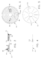
- Fig. 1 is a schematic view of a system for mixing bone cement;
- Fig. 2 is a side view in section of the cap portion of the container shown in Fig. 1;
- Fig. 3 is a bottom view of the cap portion of the container shown in Fig. 1;
- Fig. 4 is a side view in section of the barrier means associated with the container shown in Fig. 1;
- Fig. 5 is a bottom view of the barrier means associated with the container shown in Fig. 1;
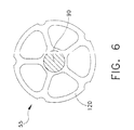
- Fig. 6 is a top view, partially in section, of the distal end of the agitator associated with the container shown in Fig. 1;
- Fig. 7 is a side view in section of one type of holder for containing the bone cement's liquid monomer component, wherein the holder comprises a syringe;
- Fig. 8 is a side view of another type of holder for containing the bone cement's liquid monomer component, wherein the holder comprises a collapsible package;
- Fig. 9 is a side view in section of still another type of holder for containing the bone cement's liquid monomer component, wherein the holder comprises an injector sleeve fit over the distal end of a glass ampoule storing the liquid monomer component;
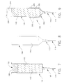
- Fig. 10 is a side view in section of an alternative form of container which can be used in conjunction with the system shown in Fig. 1;
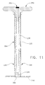
- Fig. 11 is a side view in section of the agitator associated with the container shown in Fig. 10;
- Fig. 12 is a side view in section showing the distal end of the agitator's thin-walled exterior tube being broken off, and the agitator's resilient interior tube withdrawing the porous plug, whereby the remaining stub of the thin-walled exterior tube can become an ejection port for the sealed container;
- Fig. 13 is a side view in section showing the ampoule breaker/injector device connected to the injection port of a container;
- Fig. 14 is a partial side view of the proximal end of the ampoule breaker/injector device shown in Fig. 13, except that the view of Fig. 14 has been taken at a 90 degree angle to the view of Fig. 13;
- Fig. 15 is a side view in section like that of Fig. 13, except that the glass ampoule storing the bone cement's liquid monomer component is shown moved distally within the ampoule breaker/injector device, with the distal end of the ampoule having broken off to release the liquid monomer; and
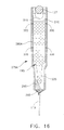
- Fig. 16 is a side view in section showing an alternative form of ampoule breaker/injector device.
- Looking first at Fig. 1, a
system 5 for mixing bone cement is shown.System 5 generally comprises acontainer 10 within which the constituent components of the bone cement are mixed under vacuum, avacuum pump 15 for pulling a vacuum, avacuum line 20 interconnectingvacuum pump 15 andcontainer 10, one ormore check valves 25 disposed invacuum line 20 for maintaining a vacuum pulled incontainer 10, avacuum indicator 30 disposed invacuum line 20 for indicating when a predetermined level of vacuum has been attained incontainer 10, and afilter 35 containing activated charcoal disposed invacuum line 20 for absorbing unwanted monomer fumes. - In accordance with the present invention, the bone cement's powdered polymer and/or copolymer component is pre-packaged in sealed
container 10, and the bone cement's liquid monomer component is pre-packaged in a separate holder. - Still looking now at Fig. 1,
container 10 comprises acontainer body 40 filled with the bone cement's powdered polymer orcopolymer component 45, acap 50 for sealing offcontainer body 40, and anagitator 55 for mixing the bone cement's constituent components withincontainer 10. - For purposes of the present invention,
container body 40 can comprise a cartridge for a cement dispenser, in whichcase container body 40 can be mounted directly in a cement dispenser after the bone cement has been mixed under vacuum. Alternatively,container body 40 can comprise a simple mixing bowl or other vessel, in which case the bone cement is transferred to a cartridge for a cement dispenser after the bone cement has been mixed incontainer 10. In Fig. 1,container body 40 is shown to be a cartridge for a cement dispenser, and to this end it includes adrive plug 60 which can be urged down the length ofcontainer body 40 so as to eject cement from the cartridge, in ways well known in the art. - Looking next at Figs. 1-5,
container cap 50 seals off the distal end ofcontainer body 40 so as to form the sealedcontainer 10.Cap 50 includes acap housing 65, barrier means 70 (Figs. 1, 4 and 5) disposed on the distal side ofcap 50, anexhaust port 75 for connection tovacuum line 20, anabsorbent filter 78 disposed inexhaust port 75 for preventing unwanted materials (e.g., powdered polymer or copolymer, liquid monomer, and/or mixed cement) from passing out ofcontainer 10 throughexhaust port 75, and aninjection port 80 for connection to the holder containing the bone cement's liquid monomer component. - Looking next at Figs. 2 and 3,
cap housing 65 includes anopening 85 to receive the shaft 90 (Fig. 1) ofagitator 55.Cap housing 65 also includes anopening 95 which makes up part ofexhaust port 75, anopening 100 which makes up part ofinjection port 80, and shallow surface grooves 105 (Fig. 3) which are formed on the underside ofcap housing 65. Surface grooves 105 cooperate with barrier means 70 to provide "indirect pathways" between the interior ofcontainer 10 andexhaust port 75, as will hereinafter be discussed in further detail. - Looking next at Figs. 1, 4 and 5, barrier means 70 are disposed adjacent the distal side of
cap housing 65. Barrier means 70 are formed out of a non-porous material such as polyethylene. Barrier means 70 are formed in the shape of a thin disk and includes acentral hole 110 and a plurality of radial slits 115 (Fig. 5).Central hole 110 is sized so as to accommodateshaft 90 ofagitator 55. Radial slits 115 cooperate with surface grooves 105 ofcap housing 65 so as to define a plurality of indirect pathways extending between the interior ofcontainer 10 andexhaust port 75. These indirect pathways permit gas to pass out ofcontainer 10 viaexhaust port 75, whereby the interior ofcontainer 10 can be placed into a vacuum condition, but prevent solid and/or liquid material from passing out ofcontainer 10 viaexhaust port 75. This helps protect the one ormore check valves 25 and/or thevacuum pump 15, which elements are located downstream invacuum line 20. Preferably multiple indirect paths are provided, so that gas evacuation can continue even if one or more paths become blocked with solids and/or liquids. -
Exhaust port 75 is a valved connector arrangement which coacts with a counterpart connector arrangement 118 (Fig. 1) disposed on the distal end ofvacuum line 20 so as to permitvacuum pump 15 to evacuate air fromcontainer 10.Connector arrangement 118, located on the distal end ofvacuum line 20, and the counterpart valved connector arrangement ofexhaust port 75, located oncontainer 10, may comprise any one of the many connector sets well known in the art. Such connector sets typically utilize a male-female coupling, with the valved connector arrangement ofexhaust port 75 including some sort of check valve arrangement so as to renderexhaust port 75 self-sealing when it is not being engaged byconnector arrangement 118. By way of example,connector arrangement 118 might comprise something equivalent to the blunt inflation pump cannulas of the type commonly used to inflate an ordinary basketball or football, and the valved connector arrangement ofexhaust port 75 might comprise something equivalent to the rubber self-sealing inflation ports used on such basketballs and footballs. Alternatively, the counterpart connectors might comprise a Clave™ valve Needleless Connector (ICU Medical Inc., Irvine, CA), or an InterLink™ System (Baxter Healthcare Corporation, Deerfield, IL) injection port with pre-slit septum in combination with an InterLink™ cannula (Becton Dickinson & Co., Franklin Lake, NJ). For the purposes of the present invention, the principal requirements forconnector arrangement 118 and the valved connector arrangement ofexhaust port 75 are that (i) they are capable of making an airtight connection when they are in engagement with one another, and (ii) the valved connector arrangement ofexhaust port 75 is self-sealing when connector arrangement 118 (and hence the distal end of vacuum line 20) is disconnected fromcontainer 10. -
Absorbent filter 78 is disposed inexhaust port 75, downstream from barrier means 70 but upstream fromvacuum line 20.Absorbent filter 78 serves to remove any material (e.g., powdered polymer and/or copolymer, liquid monomer, and/or mixed cement) that may get past the indirect pathways discussed above.Absorbent filter 78 is preferably made from a cellulose material of the sort well known in the art. -
Injection port 80 is a valved connector arrangement which coacts with a counterpart connector arrangement 119 (Fig. 7) disposed on the distal end of a holder containing the bone cement's liquid monomer component so as to permit liquid monomer to be introduced intocontainer 10.Connector arrangement 119, located on the distal end of a holder containing the bone cement's liquid monomer component, and the counterpart valved connector arrangement ofinjection port 80, located oncontainer 10, may comprise any one of the many connector sets well known in the art. Such connector sets typically utilize a male-female coupling, with the valved connector arrangement ofinjection port 80 including some sort of check valve arrangement so as to renderinjection port 80 self-sealing when it is not being engaged byconnector arrangement 119. By way of example,connector arrangement 119 might comprise something equivalent to the blunt inflation pump cannulas of the type commonly used to inflate an ordinary basketball or football, and the valved connector arrangement ofinjection port 80 might comprise something equivalent to the rubber self-sealing inflation ports used on such basketballs and footballs. Alternatively, the counterpart connectors might comprise a Clave™ valve Needleless Connector (ICU Medical Inc., Irvine, CA), or an InterLink™ System (Baxter Healthcare Corporation, Deerfield, IL) injection port with pre-slit septum in combination with an InterLink™ cannula (Becton Dickinson & Co., Franklin Lake, NJ). For the purposes of the present invention, the principal requirements forconnector arrangement 119 and the valved connector arrangement ofinjection port 80 are that (i) they are capable of making an airtight connection when they are in engagement with one another, and (ii) the valved connector arrangement ofinjection port 80 is self-sealing when connector arrangement 119 (and hence the holder containing the bone cement's liquid monomer component) is disconnected fromcontainer 10. - Looking next at Figs. 1 and 6,
agitator 55 comprises ashaft 90 having a mixingpaddle 120 disposed at its distal end and a T-shapedhandle 125 disposed at its proximal end. T-shapedhandle 125 comprises a pair oflateral extensions 127.Agitator 55 is disposed so that itsshaft 90 extends through opening 85 incap 50 andopening 110 in barrier means 70, whereby the agitator's mixingpaddle 120 can be urged to mix the cement components located in the interior of sealedcontainer 10 by means ofhandle 125. In particular,agitator 55 is arranged so that reciprocal movement ofhandle 125 relative tocontainer 10 will cause mixingpaddle 120 to move in a reciprocal fashion within the interior ofcontainer 10. -
Vacuum pump 15,vacuum line 20, the one ormore check valves 25,vacuum indicator 30, and filter 35 are all preferably of the sort disclosed in pending U.S. Patent Application Serial No. 08/577698, filed December 22, 1995 by Kwan-Ho Chan for VACUUM SYSTEM, which application is hereby incorporated herein by reference. Alternatively,vacuum pump 15,vacuum line 20, the one ormore check valves 25,vacuum indicator 30, and filter 35 can be generally equivalent elements of the sort well known in the art. - Looking next at Fig. 7, a
holder 130 is shown for containing the bone cement's liquid monomer component.Holder 130 comprises anelongated cavity 135 for containing a supply ofliquid monomer 140, anegress port 145 terminating in aconnector arrangement 119 of the sort described above, and a slidingpiston 155.Piston 155 closes off the rear end ofelongated cavity 135 and has itsproximal surface 160 exposed to the ambient atmosphere.Piston 155 is adapted to make a close sliding fit with the walls ofcavity 135, wherebypiston 155 can move distally withincavity 135 as the liquid monomer is withdrawn from the holder, as will hereinafter be discussed in further detail. -
System 5 can be used to mix bone cement as follows. First, holder 130 (Fig. 7) is connected to the sealed container'sinjection port 80. This is done by engagingconnector arrangement 119 ofmonomer holder 130 with the valved connector arrangement of injection port 80 (Fig. 1). Thenvacuum line 20 is connected toevacuation port 75. This is done by engagingconnector arrangement 118 ofvacuum line 20 with the valved connector arrangement of evacuation port 75 (Fig. 1). Thenvacuum pump 15 is used to pull a vacuum incontainer 10, whereby the air present incontainer 10 will be evacuated from the container, and whereby liquid monomer 140 (Fig. 7) stored inholder 130 will be drawn intocontainer 10 and into contact with the powdered polymer and/or copolymer stored incontainer 10.Next agitator 55 is used to mixliquid monomer 140 with the powdered polymer and/or copolymer 45 (Fig. 1) so as to form the desired bone cement. Thevacuum line 20 may be disconnected from the container'sexhaust port 75 before or after mixing. The mixed cement is then ready to be used, either directly incontainer 10 if the container is the form of a cartridge for a cement dispenser, or by transferring the mixed cement fromcontainer 10 into a cartridge for a cement dispenser ifcontainer 10 is a simple mixing bowl or other vessel. - Looking next at Fig. 8, another
holder 165 is shown for containing the bone cement's liquid monomer component.Holder 165 comprises acollapsible package 170 having anegress port 175 terminating in aconnector arrangement 119 of the sort described above. With the arrangement ofholder 165, whenholder 165 is connected tocontainer 10 and a vacuum is then drawn incontainer 10, ambient atmospheric pressure will act oncollapsible package 170 so as to cause the liquid monomer to pass out ofholder 165 and intocontainer 10. - Looking next at Fig. 9, yet another
holder 185 is shown for containing the bone cement's liquid monomer component.Holder 185 comprises aninjector sleeve 190 which is fit over the distal end of aglass ampoule 195. -
Injector sleeve 190 includes anegress port 200 terminating in aconnector arrangement 119 of the sort described above. O-rings 205 are disposed in the inside side wall ofinjector sleeve 190, to make an airtight seal withampoule 195. -
Ampoule 195 has a traditional configuration which includes an easily fractured neck at one end.Ampoule 195 holds the bone cement'sliquid monomer component 140. In addition, and quite significantly,ampoule 195 also preferably holds agas column 210.Gas column 210 is provided to facilitate withdrawal of the monomer component from the fixed volume glass ampoule vessel by a vacuum. In fact, whenampoule 195 is in communication withcontainer 10 and a vacuum is thereafter drawn in that container,gas column 210 will effectively expand in the ampoule as the vacuum is drawn in the container until the pressure ofgas column 210 inampoule 195 equilibrates with the level of the vacuum incontainer 10. Thus, the expandinggas column 210 effectively expelsmonomer 140 fromampoule 195 and intocontainer 10 as a vacuum is established incontainer 10. - The minimum volume of gas required to completely expel
monomer 140 fromampoule 195 under the influence of the vacuum incontainer 10 is governed by Boyle's Law, as follows:
- Vo = volume of gas in
ampoule 195 - Po = pressure of gas in
ampoule 195 - VM = volume of monomer in
ampoule 195 - Pc = vacuum level in container 10 (assumed to be constant).
- By way of example, suppose the volume of monomer in ampoule 195 (i.e., VM) is 40 cc, the pressure of gas in ampoule 195 (i.e., Po) is 30 mm Hg, the ambient atmospheric pressure is 30 mm Hg, the vacuum in container 10 (i.e., Pc) is 22 mm HG below ambient atmospheric pressure
(i.e., 30 mm HG - 22 mm HG = 8 mm HG), then

- In practice, since the surface tension of
monomer 140 is very low, the monomer will tend to flow out ofampoule 195 under the influence of gravity alone. In other words, the monomer will flow out ofampoule 195 even if the minimum volume of gas required to completely expelmonomer 140 fromampoule 195 is not met.Monomer 40 will, of course, flow out ofampoule 195 much better when the volume and pressure requirement are met. And, as might be expected, the system will work best ifgas column 210 is sealed inampoule 195 under pressure. - In use, the easily fractured neck of
ampoule 195 is broken off by snapping it along a prescored line which is provided for this purpose. This effectively opensampoule 195.Next injector sleeve 190 is slipped over the open end ofglass ampoule 195. O-rings 205seal vessel 195 withininjector sleeve 190. On account of this construction, whenholder 185 is connected tocontainer 10 and a vacuum is then drawn incontainer 10, thegas column 210 disposed aboveliquid monomer 140 will expand so that the liquid monomer will flow out of the holder and intocontainer 10. In this respect it is also to be appreciated that, whenholder 185 is connected up tocontainer 10 and a vacuum is then drawn incontainer 10, atmospheric pressure acting on thetop surface 220 ofglass ampoule 195 will urge the ampoule further down intoinjector sleeve 190, if the ampoule is not already maximally advanced into the injector sleeve. - Looking next at Figs. 10-12, an
alternative container 10A is disclosed which can be used in place of thecontainer 10 insystem 5.Container 10A is identical to thecontainer 10 previously disclosed, except as will hereinafter be discussed. - First,
container 10A is generally intended to comprise acontainer body 40A which is in the form of a cartridge for a cement dispenser.Container body 40A is generally not intended to be in the form of a sealed mixing bowl or other non-cartridge vessel, as might be the case with thecontainer body 40 previously disclosed. Of course, it should also be appreciated that nothing in the present invention requires thatcontainer body 40A be in the form of a cartridge for a cement dispenser; it is merely anticipated that this will be the most useful form forcontainer body 40A. - Second,
container 10A has acap 50A which is identical to thecap 50 previously disclosed, except thatcap 50A omits theinjection port 80 previously disclosed in connection withcontainer 10. Furthermore, if desired, the indirect pathways of container 10 (constituted by the surface grooves 105 formed in the cap's bottom surface and by the radial slits 115 formed in barrier means 70) may be omitted incontainer 10A. In such a case, alternative barrier means 70A may be provided, wherein such barrier means 10A are formed out of a porous or semi-porous material such that barrier means 70A can serve to minimize any undesired materials (e.g., powdered polymer and/or copolymer, liquid monomer, and/or mixed cement) from passing into the container'sexhaust port 75, while still permitting gas to be evacuated fromcontainer 10A throughexhaust port 75. - Third,
container 10A includes anagitator 55A which differs significantly from theagitator 55 previously disclosed in connection withcontainer 10.Agitator 55A comprises a thin-walled exterior tube 225 having a breakaway notch 230 (Figs. 10 and 11) formed near its distal end, a resilientinterior tube 235 disposed inside the thin-walled exterior tube 225, aperforated disk 240 disposed at the distal end of thin-walled exterior tube 225 and resilientinterior tube 235, aporous plug 245 closing off the distal end of resilientinterior tube 235, a T-shapedhandle 250 connected to the top ends of thin-walled exterior tube 225 and resilientinterior tube 235, and aninjection port 255 formed inhandle 250. - Thin-
walled exterior tube 225 is formed out of breakable plastic, e.g., polyethylene.Breakaway notch 230 is formed near the distal end of thin-walled exterior tube 225, and preferably comprises a peripheral groove formed in the outer surface of the tube.Breakaway notch 230 permits thin-walled exterior tube 225 to be broken off in a snapping action, as will hereinafter be discussed in further detail. - Resilient
interior tube 235 is disposed within thin-walled exterior tube 225.Interior tube 235 is formed out of a resilient material which will flex but remain intact when thin-walled exterior tube 225 is broken off at itsbreakaway notch 230 in a snapping motion. At the same time, however,interior tube 235 is formed out of a material which is sufficiently rigid in an axial direction such thatporous plug 245 will remain securely in place withinagitator 55A when the agitator is used to mix bone cement withincontainer 10A, as will hereinafter be discussed in further detail. Resilientinterior tube 235 is preferably formed out of plasticized polyvinylchloride (PVC) or silicone. -
Perforated disk 240 is identical to theperforated disk 120 described above in connection withagitator 55, except thatperforated disk 240 includes an opening 260 (Figs. 11 and 12) at its center. Opening 260 inperforated disk 240 receives, and is joined to, the distal end of thin-walled exterior tube 225 (Figs. 10 and 11), whereby the thin-walled exterior tube 225 can be used to moveperforated disk 240 distally and proximally withincontainer 10A so as to mix the contents ofcontainer 10A. As such mixing occurs, the distal end of resilientinterior tube 235 andporous plug 245 will be exposed to the contents ofcontainer 10A (Figs. 10 and 11). -
Porous plug 245 closes off, and is securely fastened to, the distal end of resilientinner tube 235.Porous plug 245 is formed so that it will prevent powdered polymer and/or copolymer material from getting into the central passageway of resilientinner tube 235, yet still permit air and liquid monomer to pass through the plug. In this way, the creation of a vacuum within the body ofcontainer 10A can be used to draw liquid monomer downward frominjection port 255, whereby the liquid monomer will pass down the length of resilientinterior tube 235, throughporous plug 245 and then enter the interior ofcontainer 10A. - Handle 250 is secured to both thin-
walled exterior tube 225 and resilientinterior tube 235. As a result, handle 250 can be used to move the agitator'sperforated disk 240 in a reciprocal motion within the interior ofcontainer 10A, yet can also be used to withdraw resilientinterior tube 235 andporous plug 245 fromcontainer 10A once the thin-walled exterior tube 225 has been snapped off along itsbreakaway notch 230, as will hereinafter be discussed in further detail. Handle 250 preferably comprises a pair of lateral extensions 265 (Fig. 10). -
Injection port 255 is formed inhandle 250.Injection port 255 comprises a valved opening for introducing liquid monomer into the interior passageway of resilientinterior tube 235. To this end,injection port 255 comprises a valved connector arrangement of the sort adapted to form an airtight seal with itscounterpart connector arrangement 119 formed on a monomer holder, e.g. a holder such as holder 130 (Fig. 7), holder 165 (Fig. 8) and/or holder 185 (Fig. 9). In particular,injection port 255 incontainer 10A can be substantially the same as theinjection port 80 disclosed in connection withcontainer 10 except, of course, for the fact thatinjection port 255 is formed inhandle 250 and provides an entryway to the interior of resilientinterior tube 235, whereas theinjection port 80 associated withcontainer 10 is disposed in that container'scap 50 and opens directly on the interior of that container. - It is to be noted that the sealed
container 10A is prefilled with an appropriate supply of the bone cement's powdered polymer and/or copolymer component. -
Container 10A is intended to be used withsystem 5 as follows. First, a monomer holder (e.g., amonomer holder 130 as shown in Fig. 7, or amonomer holder 165 as shown in Fig. 8, or amonomer holder 185 as shown in Fig. 9, or some other such holder) is connected to theinjection port 255 formed inhandle 250. This is done by engagingconnector arrangement 119 of the monomer holder with the valved connector arrangement ofinjection port 255 so as to establish an airtight connection. Thenvacuum line 20 is connected to the container'sevacuation port 75. This is done by engaging connector arrangement 118 (Fig. 1) ofvacuum line 20 with the valved connector arrangement ofevacuation port 75 so as to establish an airtight connection. Next, a vacuum is pulled incontainer 10A usingvacuum pump 15. This vacuum draws the bone cement's liquid monomer component out of its holder and down the interior passageway of resilientinterior tube 235, whereupon the liquid monomer component passes throughporous plug 245 and enters the interior ofcontainer 10A to join the bone cement's powdered polymer and/or copolymer component. Then the monomer holder is disconnected frominjection port 255, andagitator 55A is used to mix the cement incontainer 10A by movingperforated disk 240 back and forth within the container. Next,vacuum line 20 is disconnected fromcontainer 10A, andagitator 55A is retracted relative tocontainer 10A (i.e.,agitator 55A is moved so that itsperforated disk 240 resides adjacent to barrier means 70 or 70A, depending on which type of barrier means may be provided). Then the proximal end of thin-walled exterior tube 225 is snapped off atbreakaway notch 230 so as to provide a stub 266 (Fig. 12), and the proximal end ofagitator 55A is withdrawn fromcontainer 10A, carrying resilientinterior tube 235 andporous plug 245 away from thecontainer 10A. This leaveshollow stub 266 clear and thecontainer 10A ready to be loaded into a cement dispenser of the sort well known in the art, whereupon the mixed cement withincontainer 10A can be dispensed out thehollow stub 266. Preferablybreakaway notch 230 on the thin-walled exterior tube 225 is positioned such thatstub 265 will lie substantially flush with a cap projection 267 (Figs. 10 and 12) after the proximal end ofagitator 55A is removed fromcontainer 10A, whereby various nozzle fixtures can be easily mounted to capprojection 267 so as to facilitate dispensing of bone cement. - Looking next at Figs. 13-15, another
container arrangement 270 is shown which can be used withsystem 5.Container arrangement 270 comprises acontainer 10 of the sort previously described and shown in Figs. 1-6, and an ampoule breaker/injector 275 which is connected to the container'sinjection port 80. Ampoule breaker/injector 275 is arranged so that it will automatically (i) break aglass ampoule 195 of the sort shown in Figs. 9 and 13 when a vacuum is established incontainer 10, and (ii) direct the released monomer liquid into the container'sinjection port 80. More particularly, ampoule breaker/injector 275 acts as a caddy for theampoule 195 until a vacuum is to be drawn incontainer 10 and the liquid monomer in the ampoule is to be used, at which time ampoule breaker/injector 275 facilitates release of the liquid monomer from the ampoule, and then directs the liquid monomer through the container'sinjection port 80 and into contact with powdered polymer and/or copolymer powder previously packaged in the sealedcontainer 10. The volume of the gas column used to efficiently expel the liquid monomer from the ampoule is as previously described in connection with the arrangement shown in Fig. 9. - Ampoule breaker/
injector 275 comprises anelongated body 280, aconnector arrangement 119 disposed at the distal end ofbody 280, aninternal wedge 290 set near the distal end ofbody 280, aglass trap 295 disposed betweenwedge 290 andconnector arrangement 119, and aproximal piston 300 having an associated O-ring 305. AU-shaped groove 310 is formed in the proximal end ofbody 280, as will hereinafter be disclosed in further detail. -
Elongated body 280 is adapted to supportglass ampoule 195 so that it is axially aligned withcontainer 10, and so that the ampoule can make a sliding fit within the interior ofelongated body 280. -
Connector arrangement 119 is disposed at the distal end ofelongated body 280.Connector arrangement 119 is in fluid communication with the interior ofelongated body 280. As discussed above,connector arrangement 119 is of the sort adapted to form an airtight seal with the valved connector arrangement ofinjection port 80, as also discussed above. -
Internal wedge 290 is set near the distal end ofelongated body 280.Wedge 290 is fixed to the internal side wall ofelongated body 280.Wedge 290 is set at an angle to the longitudinal axis of the elongated body, whereby the leading tip of aglass ampoule 195 located withinelongated body 280 will break off when that ampoule is driven distally againstwedge 290. In essence,wedge 290 translates the distal movement ofglass ampoule 195 into the lateral movement used to break off the leading tip of the ampoule and release its liquid monomer. -
Glass trap 295 is disposed withinelongated body 280, betweeninternal wedge 290 andconnector arrangement 119.Glass trap 295 permits liquid monomer (released by the broken ampoule 195) to pass through toconnector arrangement 119, whereupon the liquid monomer will enter the interior ofcontainer 10; at the same time, however,glass trap 295 prevents glass chards from the broken ampoule from reaching the bone cement's powder polymer and/or copolymer component which is disposed incontainer 10. -
Piston 300 is disposed in the proximal end ofelongated body 280, so that the piston's O-ring 305 is positioned on the distal side ofU-shaped groove 310. The piston's associated O-ring 305 forms an airtight seal with the interior wall ofelongated body 280. The distal end surface 312 (Fig. 13) ofpiston 300 contacts theproximal end surface 315 ofampoule 195. The O-ring 305 is disposed distal to the lowest point of theU-shaped groove 310. - As a result of the foregoing construction, when a vacuum is drawn within
container 10 usingvacuum pump 15, this vacuum will extend up into the interior ofelongated body 280, thereby urgingpiston 300 to travel distally withinelongated body 280. The movingpiston 300 in turn drivesampoule 195 distally, so that the leading nose of the glass ampoule is driven againstinternal wedge 290, thereby breaking off at the prescored neck of the ampoule and releasing the liquid monomer contained in the ampoule. This liquid monomer is then drawn down intocontainer 10 by the same vacuum, whereby the monomer will mix with the powdered polymer and/or copolymer previously packed intocontainer 10. Preferablyampoule 195 includes thegas column 210 previously discussed. - Preferably,
piston 300 has an enlarged cross-section relative toampoule 195, as shown in Figs. 13-15, so as to generate greater driving force on the top end of the ampoule. -
U-shaped groove 310 is formed at the proximal end of elongated body 280 (Figs. 13 and 14).Groove 310 is sized so as to accept one of thelateral extensions 127 ofhandle 125. Preferably the top end ofgroove 310 is narrowed slightly as shown at 325 (Fig. 14) so as to releasably hold alateral handle extension 127 ingroove 310. The positioning of alateral handle extension 127 ingroove 310 serves to stabilize the proximal end ofelongated body 280 relative toagitator shaft 90. Furthermore, since the agitator'shandle 125 will tend to be drawn downward as a vacuum is drawn incontainer 10,groove 310 provides a guide for one of the distally-movinglateral handle extensions 127. Additionally, sincegroove 310 permits one of thelateral handle extensions 127 to remain in engagement with the top of the distally-movingpiston 300, the force generated by the movinglateral handle extension 127 will combine with the force generated by the movingpiston 300 so as to assist in the breakage ofglass ampoule 195. Furthermore, in the event that the vacuum created incontainer 10 is unable to drivepiston 300 distally with sufficient force to break the glass neck of the ampoule, the presence ofgroove 310 permits the user to manually depresshandle 125 so as to increase the distal pressure applied to the ampoule, wherebyampoule 195 can be broken. - The container arrangement shown in Figs. 13-15 is intended to be used as follows. First ampoule breaker/
injector 275 is connected to the container'sinjection port 80. This is done by engagingconnector arrangement 119 of ampoule breaker/injector 275 with the valved connector arrangement ofinjection port 80. Then anampoule 195 is loaded into the interior ofelongated body 280.Next piston 300 is set atopampoule 195. Then one of thelateral extensions 127 ofhandle 125 is set inU-shaped groove 310, so that the lateral extension contacts the top surface ofpiston 300.Next vacuum line 20 is connected to exhaustport 75 on container 10 (not shown in Figs. 13-15, but shown in Figs. 1 and 2). This is done by engagingconnector arrangement 118 ofvacuum line 20 with the valved connector arrangement ofexhaust port 75. Then a vacuum is pulled incontainer 10, usingvacuum pump 15. Creation of a vacuum within the interior ofcontainer 10 causespiston 300 to move distally withinelongated body 280, driving the distal end ofampoule 195 againstinternal wedge 290. At the same time, creation of a vacuum withincontainer 10causes agitator 55 to move distally, whereupon thelateral extension 127 ofhandle 125 disposed ingroove 310 will bring additional distally-directed force to bear on the proximal end ofpiston 300. Additionally, further downward force can be applied to the proximal end ofampoule 195 by manually pressing down onhandle 125 if necessary. As a result of the foregoing, the distal end ofampoule 195 will be driven againstinternal wedge 290 so that the ampoule's glass neck will be broken off, thereby releasing the liquid monomer contained in ampoule 195 (Fig. 15). This monomer liquid will then pass down into the interior ofcontainer 10, where it will come into contact with the bone cement's powdered polymer and/or copolymer component which was previously packaged in the sealed container. Then ampoule breaker/injector 275 is dismounted fromcontainer 10 and the liquid and solid cement components disposed incontainer 10 are mixed together usingagitator 55. Finallyvacuum line 20 is disconnected from the container'sexhaust port 75. The mixed cement is then ready to be used, either directly incontainer 10 ifcontainer 10 is in the form of a cartridge for a cement dispenser, or by thereafter transferring the mixed cement fromcontainer 10 into a cartridge for a cement dispenser if thecontainer 10 is a simple mixing bowl or other non-cartridge vessel. - Looking next at Fig. 16, an alternative form of ampoule breaker/
injector 275A is shown. Ampoule breaker/injector 275A is similar to the ampoule breaker/injector 275 previously disclosed, except that the proximal end ofelongated body 280A does not have an enlarged cross-section relative to the middle portion of the elongated body, andpiston 300 has been replaced by one or more 0-rings 330 mounted in annular grooves formed in the side wall ofelongated body 275A. O-rings 330 make a close sliding fit with the outside wall ofglass ampoule 195. O-rings 330 are disposed distal to the lowest point of theU-shaped groove 310. With the arrangement shown in Fig. 16, application of a vacuum toconnector arrangement 119 will create a vacuum within thespace 335 in the assembly, thereby causingampoule 195 to move distally againstwedge 290 so as to break the leading neck of the glass ampoule and thereby release the monomer fluid held therein. - It is, of course, possible to modify the preferred embodiments disclosed above without departing from the scope of the present invention.
- Thus, for example, one could substitute a plurality of perforated holes for the radial slits formed in barrier means 70.
- Or one could substitute a rotary-type agitator for the reciprocal-type agitator disclosed above. With such an alternative arrangement, the agitator's paddle element would move circumferentially about the perimeter of the container, rather than back and forth along its length.
- Furthermore, one could use another type of barrier means with the
container 10 shown in Figs. 13-15, e.g., one could use the porous or semi-porous barrier means 70A previously discussed in the context ofcontainer 10A. - Also, ampoule breaker/
injector 275 or ampoule breaker/injector 275A could be used withcontainer 10A if desired, in which case the monomer would be injected into the handle of the agitator. - Still other modifications will be obvious to a person skilled in the art, and are considered to fall within the scope of the present invention.
- Significant advantages are achieved through the use of the present invention.
- For one thing, the present invention provides an improved system for mixing bone cement.
- For another thing, the present invention provides a more convenient system for mixing bone cement in a vacuum in an operating room environment.
- And the present invention provides an improved method for mixing bone cement.
- Additionally, the present invention provides a more convenient method for mixing bone cement in a vacuum in an operating room environment.
Claims (26)
- Apparatus for mixing bone cement in a vacuum, said apparatus comprising:
a container for mixing first and second components of a bone cement in a vacuum, said container comprising:a sealed body defining an interior space;a selected quantity of said bone cement first component disposed in said interior space of said sealed body;an injection port formed in said sealed body and communicating with said interior space, said injection port being adapted for interconnection with a holder containing a selected quantity of the bone cement second component, whereby the second component can be introduced into said interior space of said sealed body;an exhaust port formed in said sealed body and communicating with said interior space, said exhaust port being adapted for interconnection with a vacuum source whereby a vacuum can be pulled inside said interior space of said sealed body;an agitator comprising a mixing paddle disposed in said interior space of said sealed body and an actuating handle therefor disposed outside said sealed body; anda plurality of indirect pathways extending between said interior space of said sealed body and said exhaust port, said plurality of indirect pathways being adapted to permit gas to pass out of said interior space of said sealed body via said exhaust port but to prevent said bone first component and the bone cement second component from passing out of said interior space of said sealed body via said exhaust port. - Apparatus according to claim 1 wherein said plurality of indirect pathways are formed at least in part by barrier means disposed between said interior space of said sealed body and said exhaust port, said barrier means comprising an element formed out of non-porous material, with said element having a plurality of passageways extending through said element.
- Apparatus according to claim 2 wherein said element is positioned against an interior surface of said sealed body, and further wherein said interior surface of said sealed body includes a plurality of surface passageways formed therein, said passageways in said barrier means and said surface passageways in said sealed body together forming said indirect pathways.
- Apparatus according to claim 1 wherein said container further comprises an absorbent filter disposed in said exhaust port so that said absorbent filter is located downstream from said indirect pathways but upstream from any vacuum source interconnected with said exhaust port, said absorbent filter being adapted to trap non-gaseous materials exiting the interior of said sealed body via said exhaust port.
- Apparatus according to claim 1 wherein said container comprises a sealed cartridge adapted for use in a cement dispenser.
- Apparatus according to claim 1 wherein said container comprises a sealed mixing bowl.
- Apparatus according to claim 1 wherein said agitator comprises a reciprocal agitator adapted to move said mixing paddle reciprocally within said interior space of said sealed body when said actuating handle is moved reciprocally outside said sealed body.
- Apparatus according to claim 1 wherein said apparatus further comprises:a vacuum line interconnecting said exhaust port with a vacuum source;a check valve disposed in said vacuum line for maintaining a vacuum pulled in the interior of said sealed body by said vacuum source;a vacuum indicator disposed in said vacuum line for indicating when a predetermined level of vacuum has been attained in the interior of said sealed body; anda filter disposed in said vacuum line for trapping selected materials passing through said vacuum line.
- Apparatus according to claim 8 wherein said filter is disposed between said vacuum indicator and said check valve.
- Apparatus for mixing bone cement in a vacuum, said apparatus comprising:
a container for mixing first and second components of a bone cement in a vacuum, said apparatus comprising:a sealed body defining an interior space;a selected quantity of said first bone cement component disposed in said interior space of said sealed body;an exhaust port formed in said sealed body and communicating with said interior space, said exhaust port being adapted for interconnection with a vacuum source whereby a vacuum can be pulled inside said interior space of said sealed body;an agitator comprising a mixing paddle disposed in said interior space of said sealed body and an actuating handle disposed outside said sealed body, with said mixing paddle being connected to said actuating handle by a hollow shaft extending through said sealed body;said hollow shaft comprising a thin-walled exterior tube and a resilient interior tube, with said thin-walled exterior tube being connected to said mixing paddle, and with said thin-walled exterior tube being provided with a breakaway notch adjacent to where said thin-walled exterior tube is connected to said mixing paddle, and with a porous plug being disposed in the central passageway of said resilient interior tube adjacent to where said shaft is connected to said mixing paddle, said porous plug being connected to said resilient interior tube and being adapted to permit gas and the bone cement second component to pass through said porous plug but to prevent said bone first component from passing through said porous plug; andan injection port formed in said actuating handle and communicating with the interior of said resilient interior tube, said injection port being adapted for interconnection with a holder containing a selected quantity of said bone cement second component, whereby said bone cement second component can be introduced into said interior space of said sealed body for mixing with said bone cement first component. - Apparatus according to claim 10 wherein said sealed body comprises a sealed cartridge adapted for use in a cement dispenser.
- An ampoule breaker/injector assembly for use in releasing a fluid from an ampoule having a frangible neck, and for guiding the fluid released from the ampoule into a sealed vessel, said assembly comprising:a body having an interior space for receiving the neck of the ampoule and at least a portion of a remainder of the ampoule;injector means formed in said body and communicating with said interior space, said injector means being adapted for interconnection with the sealed vessel whereby when a vacuum is drawn in the sealed vessel, the vacuum will be extended into said interior space of said body;first means for causing said ampoule to move longitudinally within said interior space when said ampoule is disposed in said interior space and a vacuum is extended into said interior space; andsecond means for causing said frangible neck of said ampoule to break when said ampoule is moved longitudinally within said interior space.
- An ampoule breaker/injector assembly according to claim 12 wherein said second means comprise a wedge disposed in said interior space.
- An ampoule breaker/injector assembly according to claim 12 wherein said first means comprise an O-ring disposed in said interior space.
- An ampoule breaker/injector assembly according to claim 14 wherein said O-ring is in engagement with said ampoule.
- An ampoule breaker/injector assembly according to claim 12 wherein said first means comprise a piston, said piston being adapted to drive said ampoule longitudinally when a vacuum is extended into said interior space.
- Apparatus for mixing bone cement in a vacuum, said apparatus comprising:a container for mixing first and second components of a bone cement in a vacuum, said container comprising:a sealed body defining an interior space;a selected quantity of said bone cement first component disposed in said interior space of said sealed body;an injection port formed in said sealed body and communicating with said interior space, said injection port being adapted for interconnection with a holder containing a selected quantity of the bone cement second component, whereby the second component can be introduced into said interior space of said sealed body;an exhaust port formed in said sealed body and communicating with said interior space, said exhaust port being adapted for interconnection with a vacuum source whereby a vacuum can be pulled inside said interior space of said sealed body;an agitator comprising a mixing paddle disposed in said interior space of said sealed body and an actuating handle therefor disposed outside said sealed body; andan ampoule breaker/injector assembly for use in releasing the bone cement second component from an ampoule having a frangible neck, and for guiding the bone cement second component released from the ampoule into said sealed body, said assembly comprising:a housing having defined space for receiving the neck of the ampoule and at least a portion of a remainder of the ampoule;injector means formed in said housing and communicating with said defined space, said injector means being adapted for interconnection with said sealed body, whereby when a vacuum is drawn in said sealed body, said vacuum will be extended into said defined space of said housing;first means for causing the ampoule to move longitudinally within said defined space when the ampoule is disposed in said defined space and a vacuum is extended into said defined space; andsecond means for causing the frangible neck of the ampoule to break when the ampoule is moved longitudinally within said defined space;whereby bone cement second component released from the ampoule into said defined space in said housing can be introduced into said interior space of said sealed body.
- Apparatus according to claim 17 wherein said apparatus is configured so that longitudinal motion of said actuating handle is transferred to the ampoule.
- Apparatus according to claim 18 wherein a portion of said actuating handle engages a portion of the ampoule.
- Apparatus according to claim 18 wherein said first means comprise a piston disposed in said housing and engageable with a portion of the ampoule, and a portion of said actuating handle engages a portion of said piston.
- Apparatus comprising:a substantially rigid vessel defining an interior region;a frangible neck formed on said vessel and communicating with said interior region of said vessel;a selected quantity of a liquid bone cement disposed in said interior region of said vessel; anda gas column disposed in said interior region of said vessel.
- A method for mixing first and second components of a bone cement, said method comprising the steps of:providing a sealed body defining an interior space and having therein a selected quantity of said first component, and having therein an injection port, an exhaust port, an agitator means disposed in said interior space and connected to a handle disposed at least in part outside of said interior space, and having indirect pathways extending between said interior space and said exhaust port but prevent said first and second components from passing out of said interior space via said exhaust port;placing a holder having said second component therein in communication with said injection port to place said holder in communication with said interior spaceplacing a vacuum source in communication with said exhaust port to draw a vacuum in said interior space, to thereby draw said second component into said interior space; andoperating said handle to move said agitator means in said interior space to mix said first and second components while continuing said drawing of said vacuum in said interior space, said pathways permitting passage of gas therethrough from said interior space but preventing passages of said first and second components therethrough.
- A method for mixing first and second components of a bone cement, said method comprising the steps of:providing a sealed body defining an interior space and having therein a selected quantity of said first component, and having therein an exhaust port, an agitator means disposed in said interior space and connected to a handle connected to said agitator means and extending outside of said interior space, and having barrier means in said interior space adjacent said exhaust port, said barrier means being adapted to permit gas to pass therethrough and out of said interior space via said exhaust port but prevent passage therethrough of said first and second components, said handle having an injection port therein outside of said interior space and a channel extending through said handle to proximate said agitator means;placing a vacuum source in communication with said exhaust port to draw a vacuum in said interior space and said, channel;introducing said second component via said injection port and said channel into said interior space; andoperating said handle to move said agitator means in said interior space to mix said first and second components to form bone cement, while continuing said drawing of said vacuum in said interior space, said barrier means permitting passage of gas therethrough from said interior space but preventing passage therethrough of said first and second components.
- Apparatus comprising:a substantially rigid vessel defining an interior region;an egress port formed on said rigid vessel and communicating with said interior region;a piston movably disposed in said interior region of said vessel and making a close sliding fit therewith so as to define a volume of variable size; anda selected quantity of a liquid bone cement component disposed in said volume.
- Apparatus comprising:a substantially flexible vessel defining an interior region;an egress port formed on said flexible vessel and communicating with said interior region; anda selected quantity of a liquid bone cement component disposed in said interior region of said flexible vessel.
- Apparatus comprising:a substantially rigid vessel defining an interior region;a frangible neck formed on said vessel and communicating with said interior region of said vessel;a selected quantity of a liquid bone cement disposed in said interior region of said vessel;a gas column disposed in said interior region of said vessel; andan injector element for receiving the neck of said vessel and at least a portion of the remainder of said vessel and for making an airtight seal with said at least a portion of the remainder of said vessel, said injector device including an egress port.
Applications Claiming Priority (2)
| Application Number | Priority Date | Filing Date | Title |
|---|---|---|---|
| US08/604,194 US5779356A (en) | 1996-02-21 | 1996-02-21 | Apparatus and method for mixing first and second components of a bone cement in a vacuum |
| US604194 | 1996-02-21 |
Publications (3)
| Publication Number | Publication Date |
|---|---|
| EP0796653A2 true EP0796653A2 (en) | 1997-09-24 |
| EP0796653A3 EP0796653A3 (en) | 1998-03-25 |
| EP0796653B1 EP0796653B1 (en) | 2004-05-26 |
Family
ID=24418586
Family Applications (1)
| Application Number | Title | Priority Date | Filing Date |
|---|---|---|---|
| EP97301103A Expired - Lifetime EP0796653B1 (en) | 1996-02-21 | 1997-02-20 | System and method for mixing bone cement |
Country Status (4)
| Country | Link |
|---|---|
| US (3) | US5779356A (en) |
| EP (1) | EP0796653B1 (en) |
| CA (1) | CA2198183C (en) |
| DE (1) | DE69729236D1 (en) |
Cited By (37)
| Publication number | Priority date | Publication date | Assignee | Title |
|---|---|---|---|---|
| EP1062028A1 (en) * | 1997-10-30 | 2000-12-27 | Physical Systems, Inc. | System for mixing multi-part reaction materials |
| EP0972499A3 (en) * | 1998-07-13 | 2001-03-28 | Stryker Technologies Corporation | Disposable monomer dispenser and vial breaker |
| EP1020167A3 (en) * | 1999-01-14 | 2001-08-01 | Bristol-Myers Squibb Company | Apparatus and method for mixing and dispensing bone cement |
| WO2001070146A2 (en) * | 2000-02-28 | 2001-09-27 | Coripharm Medizinprodukte Gmbh & Co. Kg | Preparation and application device for implant materials |
| WO2001085070A1 (en) * | 2000-05-05 | 2001-11-15 | Coripharm Medizinprodukte Gmbh & Co. Kg | Preparation and application device for materials to be prepared as a paste-like flowable mass, especially bone cement |
| EP1250951A1 (en) * | 2001-04-17 | 2002-10-23 | Fitech AG | Device for mixing and dispensing of in particular viscous or pasty materials |
| EP1252922A1 (en) * | 2001-04-17 | 2002-10-30 | Fitech AG | Commercial scale device for mixing and dispensing of in particular viscous or pasty materials |
| US6689823B1 (en) | 1999-03-31 | 2004-02-10 | The Brigham And Women's Hospital, Inc. | Nanocomposite surgical materials and method of producing them |
| EP3117895A1 (en) | 2015-07-13 | 2017-01-18 | Heraeus Medical GmbH | Vacuum mixing system and method for the mixing of polymethylmethacrylate bone cement |
| JP2017217469A (en) * | 2016-06-08 | 2017-12-14 | ヘレウス メディカル ゲーエムベーハー | Storage and mixing device for bone cement with pressure pump |
| DE102016110561A1 (en) | 2016-06-08 | 2017-12-14 | Heraeus Medical Gmbh | Storage and mixing device for producing a bone cement |
| EP3320870A1 (en) * | 2016-11-11 | 2018-05-16 | Heraeus Medical GmbH | Device and method for storing and mixing of a bone cement |
| DE102016121606A1 (en) | 2016-11-11 | 2018-05-17 | Heraeus Medical Gmbh | Bone cement applicator with bony cement driven closure system |
| DE102017107569A1 (en) | 2017-04-07 | 2018-10-11 | Heraeus Medical Gmbh | Device for storing, mixing and discharging a bone cement and method therefor |
| DE102017109255A1 (en) | 2017-04-28 | 2018-10-31 | Heraeus Medical Gmbh | Bone cement application device with closure means on the discharge piston |
| DE102017110732A1 (en) | 2017-05-17 | 2018-11-22 | Heraeus Medical Gmbh | Bone cement applicator with hollow cylinder on the discharge piston |
| DE102017113126A1 (en) | 2017-06-14 | 2018-12-20 | Heraeus Medical Gmbh | Bone cement applicator with duct element and lock receptacle |
| DE102017125592A1 (en) | 2017-11-02 | 2019-05-02 | Heraeus Medical Gmbh | Powder-liquid bone cement mixer with compressed gas connection |
| DE102017104854B4 (en) | 2017-03-08 | 2019-05-29 | Heraeus Medical Gmbh | Two-part storage and mixing device for producing a bone cement and method for this |
| DE102017130084A1 (en) | 2017-12-15 | 2019-06-19 | Heraeus Medical Gmbh | Bone cement mixing device with spacer in a vial holder |
| DE102018101041A1 (en) | 2018-01-18 | 2019-07-18 | Heraeus Medical Gmbh | Bone cement applicator with sealable gassing opening |
| DE102018209784A1 (en) | 2018-06-18 | 2019-12-19 | Heraeus Medical Gmbh | Bone cement applicator with retractable mixing stick and method for producing a bone cement |
| DE102018209807A1 (en) | 2018-06-18 | 2019-12-19 | Heraeus Medical Gmbh | Bone cement applicator with retractable mixing stick and method for producing a bone cement |
| EP3643398A1 (en) | 2018-10-25 | 2020-04-29 | Heraeus Medical GmbH | Device and method for producing bone cement |
| DE102018218302A1 (en) | 2018-10-25 | 2020-04-30 | Heraeus Medical Gmbh | Device for providing bone cement |
| DE102018218303A1 (en) | 2018-10-25 | 2020-04-30 | Heraeus Medical Gmbh | Device for providing bone cement |
| EP3662990A1 (en) | 2018-12-07 | 2020-06-10 | Heraeus Medical GmbH | Device for mixing a bone cement with a cavity for monomer transfer |
| EP3662991A1 (en) | 2018-12-07 | 2020-06-10 | Heraeus Medical GmbH | Device for mixing a bone cement with a cavity for monomer transfer |
| EP3695797A1 (en) | 2019-02-18 | 2020-08-19 | Heraeus Medical GmbH | Bone cement applicator with clampable discharge plunger |
| EP3838391A1 (en) | 2019-12-18 | 2021-06-23 | Heraeus Medical GmbH | Device for producing bone cement |
| EP4063007A1 (en) | 2021-03-22 | 2022-09-28 | Heraeus Medical GmbH | Method and device for mixing bone cement with pressure relief |
| EP4079396A1 (en) | 2021-04-22 | 2022-10-26 | Heraeus Medical GmbH | Device for producing bone cement |
| EP4154973A1 (en) | 2021-09-28 | 2023-03-29 | Heraeus Medical GmbH | Device for preparing bone cement |
| EP4257232A1 (en) | 2022-04-04 | 2023-10-11 | Heraeus Medical GmbH | Device and method for producing bone cement |
| EP4282518A1 (en) | 2022-05-23 | 2023-11-29 | Heraeus Medical GmbH | Device and method for producing bone cement |
| EP4299169A1 (en) | 2022-06-30 | 2024-01-03 | Heraeus Medical GmbH | Device and method for producing bone cement |
| EP4309774A1 (en) | 2022-07-19 | 2024-01-24 | Heraeus Medical GmbH | Method and device for providing a bone cement mass |
Families Citing this family (51)
| Publication number | Priority date | Publication date | Assignee | Title |
|---|---|---|---|---|
| SE500430C2 (en) * | 1993-05-10 | 1994-06-27 | Cemvac System Ab | Device for loading bone cement components into a pressurized mixing vessel |
| IL121968A0 (en) * | 1997-10-14 | 1998-03-10 | A R T Medical Instr Ltd | Method for depositing a microvolume of liquid on a surface and apparatus therefor and a microvolume pump therefor |
| US6116773A (en) * | 1999-01-22 | 2000-09-12 | Murray; William M. | Bone cement mixer and method |
| SE521945C2 (en) * | 1999-02-26 | 2003-12-23 | Biomet Merck Cementing Technol | Mixing device for making bone cement |
| US6770079B2 (en) * | 1999-03-16 | 2004-08-03 | American Osteomedix, Inc. | Apparatus and method for fixation of osteoporotic bone |
| US20030069545A1 (en) * | 1999-12-06 | 2003-04-10 | Arm Douglas M. | Graft delivery syringe |
| DK1395208T3 (en) | 2001-06-14 | 2007-05-07 | Cemvac System Ab | Method of producing bone cement and device for practicing the method |
| US7517694B2 (en) * | 2002-07-26 | 2009-04-14 | Ortho-Clinical Diagnostics, Inc. | Metering tip with internal features to control fluid meniscus and oscillation |
| EP1614403B2 (en) | 2003-03-14 | 2014-06-18 | Depuy Spine, Inc. | Hydraulic device for the injection of bone cement in percutaneous vertebroplasty |
| US8066713B2 (en) | 2003-03-31 | 2011-11-29 | Depuy Spine, Inc. | Remotely-activated vertebroplasty injection device |
| US20050128867A1 (en) * | 2003-05-12 | 2005-06-16 | Henniges Bruce D. | Bone cement mixing and delivery system |
| US20040267272A1 (en) | 2003-05-12 | 2004-12-30 | Henniges Bruce D | Bone cement mixing and delivery system |
| WO2006011152A2 (en) | 2004-06-17 | 2006-02-02 | Disc-O-Tech Medical Technologies, Ltd. | Methods for treating bone and other tissue |
| US8415407B2 (en) | 2004-03-21 | 2013-04-09 | Depuy Spine, Inc. | Methods, materials, and apparatus for treating bone and other tissue |
| US8579908B2 (en) | 2003-09-26 | 2013-11-12 | DePuy Synthes Products, LLC. | Device for delivering viscous material |
| US20050155901A1 (en) * | 2004-01-21 | 2005-07-21 | Krueger John A. | Surgical cement preparation system |
| US20060052760A1 (en) * | 2004-08-20 | 2006-03-09 | Ulrich Batzdorf | Bone dust accumulator |
| SE530710C2 (en) * | 2005-07-05 | 2008-08-19 | Biomet Cementing Technologies | Method and apparatus for contacting a powder and a liquid component, preferably polymer and monomer, to mix them, preferably to bone cement. |
| US9381024B2 (en) | 2005-07-31 | 2016-07-05 | DePuy Synthes Products, Inc. | Marked tools |
| US9918767B2 (en) | 2005-08-01 | 2018-03-20 | DePuy Synthes Products, Inc. | Temperature control system |
| US8360629B2 (en) | 2005-11-22 | 2013-01-29 | Depuy Spine, Inc. | Mixing apparatus having central and planetary mixing elements |
| US20070170080A1 (en) * | 2006-01-26 | 2007-07-26 | Joshua Stopek | Medical device package |
| US20070185495A1 (en) * | 2006-01-30 | 2007-08-09 | Howmedica International S. De R. L. | Plug-in syringe stand |
| CN101516412B (en) | 2006-09-14 | 2014-02-12 | 德普伊斯派尔公司 | Bone cement and use method thereof |
| AU2007311451A1 (en) | 2006-10-19 | 2008-04-24 | Depuy Spine, Inc. | Fluid delivery system |
| EP1917924A1 (en) * | 2006-11-02 | 2008-05-07 | Stryker Trauma GmbH | Implantation device |
| US7905654B1 (en) * | 2006-11-13 | 2011-03-15 | Luis Cordero | Hand held manually operated mixer |
| US8132959B2 (en) * | 2007-08-31 | 2012-03-13 | Stryker Corporation | Medical cement monomer ampoule cartridge for storing the ampoule, opening the ampoule and selectively discharging the monomer from the ampoule into a mixer |
| SE531600C2 (en) * | 2007-10-10 | 2009-06-02 | Ortoviva Ab | Mixing system and mixing procedure for medical purposes |
| US8206143B2 (en) * | 2007-12-13 | 2012-06-26 | Biomet Manufacturing Corp. | Modular articulating cement spacer |
| DE102007061696B4 (en) | 2007-12-19 | 2010-03-18 | Heraeus Medical Gmbh | Mixing device, especially for bone cements |
| US8256949B2 (en) | 2007-12-27 | 2012-09-04 | Cook Medical Technologies Llc | Apparatus and method for mixing and dispensing a bone cement mixture |
| US8317800B2 (en) * | 2008-04-22 | 2012-11-27 | Warsaw Orthopedic, Inc. | Injectable material delivery device with an integrated mixer |
| US20090281549A1 (en) * | 2008-05-12 | 2009-11-12 | Cook Incorporated | Bone cement mixing and delivery device and method of use |
| CN102066236B (en) * | 2008-07-29 | 2012-05-30 | 药物混合系统股份公司 | Device for opening a closed fluid container |
| US8480289B2 (en) | 2008-08-22 | 2013-07-09 | Biomet Manufacturing, Llc | Bone cement mixing cartridge and method of use |
| EP2379211B1 (en) | 2009-01-21 | 2013-02-13 | Medmix Systems AG | Mixing apparatus having display for pressure change |
| DE102009013211B4 (en) * | 2009-03-17 | 2012-04-19 | Aap Biomaterials Gmbh | Bone cement vacuum mixing device and method for mixing bone cement |
| US9131930B2 (en) | 2009-06-19 | 2015-09-15 | Medmix Systems Ag | Devices for filling a multi-use syringe or single-use syringe |
| WO2011082015A2 (en) * | 2009-12-31 | 2011-07-07 | Cook Incorporated | Vertebroplasty cement mixer injector device |
| DE102010004342B4 (en) * | 2010-01-11 | 2018-07-05 | App Biomaterials Gmbh | Bone cement mixing device and method for mixing bone cement |
| DE102010026497B4 (en) * | 2010-07-07 | 2014-04-03 | Heraeus Medical Gmbh | Vakuumzementiersystem |
| DE102011112516B4 (en) | 2011-09-07 | 2024-02-29 | Stryker European Operations Holdings Llc | Container with a container for holding a liquid and a liquid removal device |
| DE102011119371B3 (en) * | 2011-11-25 | 2013-04-04 | Heraeus Medical Gmbh | Device for mixing bone cement |
| DE102011119377B3 (en) | 2011-11-25 | 2013-04-04 | Heraeus Medical Gmbh | Storage and mixing device for bone cement |
| EP2834185B1 (en) * | 2012-04-03 | 2017-01-18 | Synthes GmbH | Device and method for opening an ampoule |
| US20130269826A1 (en) * | 2012-04-13 | 2013-10-17 | Kyphon Sarl | Bone Cement Component Injection System With Reduced Fume Exposure And Method |
| WO2014078506A2 (en) * | 2012-11-14 | 2014-05-22 | Ams Research Corporation | Cell delivery device and system with anti-clumping feature and methods for pelvic tissue treatment |
| US9174147B2 (en) * | 2013-03-05 | 2015-11-03 | Nordson Corporation | Device and method for removing gas from a mixture of biomaterials |
| DE102014112043A1 (en) * | 2014-08-22 | 2016-02-25 | Heraeus Medical Gmbh | Tensioned opening device for monomer containers |
| DE102015106899B3 (en) * | 2015-05-04 | 2016-07-14 | Heraeus Medical Gmbh | Device for mixing and storing polymethyl methacrylate bone cement |
Citations (8)
| Publication number | Priority date | Publication date | Assignee | Title |
|---|---|---|---|---|
| GB852436A (en) * | 1958-07-07 | 1960-10-26 | Ampins Ltd | Pressurized ampoule |
| US4185072A (en) * | 1977-02-17 | 1980-01-22 | Diemolding Corporation | Orthopedic cement mixer |
| US4475906A (en) * | 1982-09-13 | 1984-10-09 | Holzner Guenter | Partially flexible injection syringe device with pressure release valve or special breakable seal |
| US4799801A (en) * | 1987-03-18 | 1989-01-24 | Alfred Fischbach Kg Kunststoff-Spritzgubwerk | Mixing device for pasty multicomponent materials |
| EP0380867A1 (en) * | 1989-01-13 | 1990-08-08 | Kwan-Ho Chan | Vacuum, mixing cartridge for bone cement and relevant kit |
| US5306277A (en) * | 1991-12-23 | 1994-04-26 | Zimmer, Inc. | Monomer transfer device |
| EP0603871A2 (en) * | 1992-12-23 | 1994-06-29 | Volkmar Dr. Jansson | Process and apparatus for mixing and applying bone cement |
| US5545460A (en) * | 1993-06-11 | 1996-08-13 | Howmedica, Inc. | Methods and apparatus for preparing and delivering bone cement |
Family Cites Families (15)
| Publication number | Priority date | Publication date | Assignee | Title |
|---|---|---|---|---|
| US1680616A (en) | 1922-06-06 | 1928-08-14 | Horst Friedrich Wilhelm | Sealed package |
| US2679140A (en) | 1952-04-22 | 1954-05-25 | Ronson Art Metal Works Inc | Fuel storing and charging cartridge |
| US2979140A (en) * | 1957-01-28 | 1961-04-11 | Ross B Mckenzie | Moldboard plow frame construction |
| US3244331A (en) | 1964-01-24 | 1966-04-05 | Robert N Kharasch | Disposable single charge aerosol capsule |
| FR2237643B1 (en) * | 1973-07-17 | 1978-03-17 | Steiner Maurice | |
| CA1113894A (en) * | 1978-01-07 | 1981-12-08 | Hans W. Korte-Jungermann | Injection cartridge |
| US4361253A (en) * | 1980-08-04 | 1982-11-30 | Instrumentation Laboratory Inc. | Liquid transfer device |
| US4506793A (en) * | 1983-08-01 | 1985-03-26 | Cordis Corporation | Breakable vial |
| SE450545B (en) * | 1984-10-19 | 1987-07-06 | Mit Ab | PROCEDURE AND DEVICE FOR MANUFACTURING BENCEMENT FOR FIXING PROSTHESIS |
| SE447785B (en) * | 1985-12-23 | 1986-12-15 | Mit Ab | DEVICE FOR APPLIANCES TO ALLOW BENCEMENT MIXING UNDER VACUUM |
| SE462315B (en) * | 1989-05-03 | 1990-06-11 | Surgitec Ab | DEVICE FOR MANUFACTURING BENCEMENT |
| US5435645A (en) * | 1989-12-29 | 1995-07-25 | Tecres Spa | Process and apparatus for the mixing and direct emplacement of a two-component bone cement |
| SE510490C2 (en) * | 1992-02-07 | 1999-05-31 | Scandimed International Ab | Process for producing bone cement and apparatus for carrying out the process |
| DE4425218A1 (en) * | 1994-07-16 | 1996-01-18 | Merck Patent Gmbh | Device for mixing and discharging bone cement |
| US5624184A (en) * | 1995-10-10 | 1997-04-29 | Chan; Kwan-Ho | Bone cement preparation kit having a breakable mixing shaft forming an output port |
-
1996
- 1996-02-21 US US08/604,194 patent/US5779356A/en not_active Expired - Lifetime
-
1997
- 1997-02-20 DE DE69729236T patent/DE69729236D1/en not_active Expired - Lifetime
- 1997-02-20 EP EP97301103A patent/EP0796653B1/en not_active Expired - Lifetime
- 1997-02-21 CA CA002198183A patent/CA2198183C/en not_active Expired - Lifetime
-
2001
- 2001-08-13 US US09/928,674 patent/US6516977B2/en not_active Expired - Lifetime
-
2003
- 2003-02-11 US US10/365,141 patent/US20030155381A1/en not_active Abandoned
Patent Citations (9)
| Publication number | Priority date | Publication date | Assignee | Title |
|---|---|---|---|---|
| GB852436A (en) * | 1958-07-07 | 1960-10-26 | Ampins Ltd | Pressurized ampoule |
| US4185072A (en) * | 1977-02-17 | 1980-01-22 | Diemolding Corporation | Orthopedic cement mixer |
| US4475906A (en) * | 1982-09-13 | 1984-10-09 | Holzner Guenter | Partially flexible injection syringe device with pressure release valve or special breakable seal |
| US4799801A (en) * | 1987-03-18 | 1989-01-24 | Alfred Fischbach Kg Kunststoff-Spritzgubwerk | Mixing device for pasty multicomponent materials |
| EP0380867A1 (en) * | 1989-01-13 | 1990-08-08 | Kwan-Ho Chan | Vacuum, mixing cartridge for bone cement and relevant kit |
| US5100241A (en) * | 1989-01-13 | 1992-03-31 | Chan Kwan Ho | Vacuum mixing/bone cement cartridge and kit |
| US5306277A (en) * | 1991-12-23 | 1994-04-26 | Zimmer, Inc. | Monomer transfer device |
| EP0603871A2 (en) * | 1992-12-23 | 1994-06-29 | Volkmar Dr. Jansson | Process and apparatus for mixing and applying bone cement |
| US5545460A (en) * | 1993-06-11 | 1996-08-13 | Howmedica, Inc. | Methods and apparatus for preparing and delivering bone cement |
Cited By (83)
| Publication number | Priority date | Publication date | Assignee | Title |
|---|---|---|---|---|
| EP1062028A1 (en) * | 1997-10-30 | 2000-12-27 | Physical Systems, Inc. | System for mixing multi-part reaction materials |
| EP1062028A4 (en) * | 1997-10-30 | 2002-02-13 | Physical Systems | System for mixing multi-part reaction materials |
| EP0972499A3 (en) * | 1998-07-13 | 2001-03-28 | Stryker Technologies Corporation | Disposable monomer dispenser and vial breaker |
| EP1020167A3 (en) * | 1999-01-14 | 2001-08-01 | Bristol-Myers Squibb Company | Apparatus and method for mixing and dispensing bone cement |
| EP1525864A1 (en) * | 1999-01-14 | 2005-04-27 | Bristol-Myers Squibb Company | Apparatus and method for fixing and dispensing bone cement |
| US7279508B2 (en) | 1999-03-31 | 2007-10-09 | The Brigham And Women's Hospital, Inc. | Nanocomposite surgical materials and method of producing them |
| US6689823B1 (en) | 1999-03-31 | 2004-02-10 | The Brigham And Women's Hospital, Inc. | Nanocomposite surgical materials and method of producing them |
| US6796701B2 (en) * | 2000-02-28 | 2004-09-28 | Coripharm Medizinprodukte Gmbh & Co. Kg | Preparation and application device for implant materials with hand-operated pump |
| WO2001070146A2 (en) * | 2000-02-28 | 2001-09-27 | Coripharm Medizinprodukte Gmbh & Co. Kg | Preparation and application device for implant materials |
| WO2001070146A3 (en) * | 2000-02-28 | 2002-03-14 | Coripharm Medizinprodukte Gmbh | Preparation and application device for implant materials |
| WO2001085070A1 (en) * | 2000-05-05 | 2001-11-15 | Coripharm Medizinprodukte Gmbh & Co. Kg | Preparation and application device for materials to be prepared as a paste-like flowable mass, especially bone cement |
| EP1252922A1 (en) * | 2001-04-17 | 2002-10-30 | Fitech AG | Commercial scale device for mixing and dispensing of in particular viscous or pasty materials |
| EP1250951A1 (en) * | 2001-04-17 | 2002-10-23 | Fitech AG | Device for mixing and dispensing of in particular viscous or pasty materials |
| EP3117895A1 (en) | 2015-07-13 | 2017-01-18 | Heraeus Medical GmbH | Vacuum mixing system and method for the mixing of polymethylmethacrylate bone cement |
| DE102015111320A1 (en) * | 2015-07-13 | 2017-01-19 | Heraeus Medical Gmbh | Vacuum mixing system and method for mixing polymethyl methacrylate bone cement |
| AU2016204667B2 (en) * | 2015-07-13 | 2017-11-30 | Heraeus Medical Gmbh | Vacuum mixing system and method for the mixing of polymethylmethacrylate bone cement |
| US9861943B2 (en) | 2015-07-13 | 2018-01-09 | Heraeus Medical Gmbh | Vacuum mixing system and method for the mixing of polymethylmethacrylate bone cement |
| DE102015111320B4 (en) | 2015-07-13 | 2018-10-18 | Heraeus Medical Gmbh | Vacuum mixing system and method for mixing polymethyl methacrylate bone cement |
| JP2017217469A (en) * | 2016-06-08 | 2017-12-14 | ヘレウス メディカル ゲーエムベーハー | Storage and mixing device for bone cement with pressure pump |
| DE102016110564A1 (en) | 2016-06-08 | 2017-12-14 | Heraeus Medical Gmbh | Storage and mixing device for bone cement with pressure pump |
| DE102016110561A1 (en) | 2016-06-08 | 2017-12-14 | Heraeus Medical Gmbh | Storage and mixing device for producing a bone cement |
| AU2017203745B2 (en) * | 2016-06-08 | 2018-03-15 | Heraeus Medical Gmbh | Storage and mixing device for bone cement with a pressure pump |
| DE102016110564B4 (en) | 2016-06-08 | 2018-05-09 | Heraeus Medical Gmbh | Storage and mixing device for bone cement with pressure pump |
| EP3260193A1 (en) * | 2016-06-08 | 2017-12-27 | Heraeus Medical GmbH | Storage and mixing device for bone cement with a pressure pump and method for mixing bone cement |
| US10722855B2 (en) | 2016-06-08 | 2020-07-28 | Heraeus Medical Gmbh | Storage and mixing device for bone cement with a pressure pump |
| US10875000B2 (en) | 2016-06-08 | 2020-12-29 | Heraeus Medical Gmbh | Storage and mixing device for producing a bone cement |
| EP3320870A1 (en) * | 2016-11-11 | 2018-05-16 | Heraeus Medical GmbH | Device and method for storing and mixing of a bone cement |
| US11154343B2 (en) | 2016-11-11 | 2021-10-26 | Heraeus Medical Gmbh | Device and method for storing and mixing bone cement |
| DE102016121606A1 (en) | 2016-11-11 | 2018-05-17 | Heraeus Medical Gmbh | Bone cement applicator with bony cement driven closure system |
| DE102016121607A1 (en) | 2016-11-11 | 2018-05-17 | Heraeus Medical Gmbh | Apparatus and method for storing and mixing a bone cement |
| US10639088B2 (en) | 2016-11-11 | 2020-05-05 | Heraeus Medical Gmbh | Bone cement applicator with closure system driven by bone cement dough |
| DE102016121606B4 (en) | 2016-11-11 | 2019-05-02 | Heraeus Medical Gmbh | Bone cement applicator with bone cement driven closure system and method of applying a bone cement |
| EP3527157A1 (en) | 2016-11-11 | 2019-08-21 | Heraeus Medical GmbH | Device and method for storing and mixing of a bone cement |
| DE102016121607B4 (en) | 2016-11-11 | 2019-05-16 | Heraeus Medical Gmbh | Apparatus and method for storing and mixing a bone cement |
| DE102017104854B4 (en) | 2017-03-08 | 2019-05-29 | Heraeus Medical Gmbh | Two-part storage and mixing device for producing a bone cement and method for this |
| US11039872B2 (en) | 2017-04-07 | 2021-06-22 | Heraeus Medical Gmbh | Device for storage, mixing and dispensing of a bone cement, and pertinent method |
| DE102017107569A1 (en) | 2017-04-07 | 2018-10-11 | Heraeus Medical Gmbh | Device for storing, mixing and discharging a bone cement and method therefor |
| DE102017109255A1 (en) | 2017-04-28 | 2018-10-31 | Heraeus Medical Gmbh | Bone cement application device with closure means on the discharge piston |
| US11103295B2 (en) | 2017-04-28 | 2021-08-31 | Heraeus Medical Gmbh | Bone cement application device with closure on the delivery plunger |
| DE102017110732A1 (en) | 2017-05-17 | 2018-11-22 | Heraeus Medical Gmbh | Bone cement applicator with hollow cylinder on the discharge piston |
| US10987147B2 (en) | 2017-05-17 | 2021-04-27 | Heraeus Medical Gmbh | Bone cement applicator with hollow cylinder on delivery plunger |
| US10765463B2 (en) | 2017-06-14 | 2020-09-08 | Heraeus Medical Gmbh | Bone cement applicator with pipe line element and closure receptacle |
| DE102017113126A1 (en) | 2017-06-14 | 2018-12-20 | Heraeus Medical Gmbh | Bone cement applicator with duct element and lock receptacle |
| US11529600B2 (en) | 2017-11-02 | 2022-12-20 | Heraeus Medical Gmbh | Powder-liquid bone cement mixer with compressed gas connection |
| EP3479895A1 (en) | 2017-11-02 | 2019-05-08 | Heraeus Medical GmbH | Powder liquid bone cement mixer with connector for pressurised gas and method |
| DE102017125592B4 (en) | 2017-11-02 | 2019-06-19 | Heraeus Medical Gmbh | Powder-liquid bone cement mixer with compressed gas connection |
| DE102017125592A1 (en) | 2017-11-02 | 2019-05-02 | Heraeus Medical Gmbh | Powder-liquid bone cement mixer with compressed gas connection |
| DE102017130084A1 (en) | 2017-12-15 | 2019-06-19 | Heraeus Medical Gmbh | Bone cement mixing device with spacer in a vial holder |
| EP3505237A1 (en) | 2017-12-15 | 2019-07-03 | Heraeus Medical GmbH | Bone cement mixing apparatus and method with spacer in an ampoule holder |
| DE102017130084B4 (en) | 2017-12-15 | 2019-06-27 | Heraeus Medical Gmbh | Bone cement mixing device with spacer in a vial holder |
| US10765464B2 (en) | 2017-12-15 | 2020-09-08 | Heraeus Medical Gmbh | Bone cement mixing device with spacer in an ampoule receptacle |
| US11160594B2 (en) | 2018-01-18 | 2021-11-02 | Heraeus Medical Gmbh | Bone cement applicator with a closable gas supply opening |
| DE102018101041A1 (en) | 2018-01-18 | 2019-07-18 | Heraeus Medical Gmbh | Bone cement applicator with sealable gassing opening |
| DE102018209784A1 (en) | 2018-06-18 | 2019-12-19 | Heraeus Medical Gmbh | Bone cement applicator with retractable mixing stick and method for producing a bone cement |
| DE102018209807A1 (en) | 2018-06-18 | 2019-12-19 | Heraeus Medical Gmbh | Bone cement applicator with retractable mixing stick and method for producing a bone cement |
| US11109905B2 (en) | 2018-06-18 | 2021-09-07 | Heraeus Medical Gmbh | Bone cement applicator with retractable mixing rod and method for production of a bone cement |
| US11109906B2 (en) | 2018-06-18 | 2021-09-07 | Heraeus Medical Gmbh | Bone cement applicator with retractable mixing rod and method for production of a bone cement |
| EP3584004A1 (en) | 2018-06-18 | 2019-12-25 | Heraeus Medical GmbH | Bone cement applicator with retractable mixing rod and method for producing a bone cement |
| EP3584005A1 (en) | 2018-06-18 | 2019-12-25 | Heraeus Medical GmbH | Bone cement applicator with retractable mixing rod and method for producing a bone cement |
| EP3643399A1 (en) | 2018-10-25 | 2020-04-29 | Heraeus Medical GmbH | Device and method for producing bone cement |
| DE102018218303A1 (en) | 2018-10-25 | 2020-04-30 | Heraeus Medical Gmbh | Device for providing bone cement |
| EP3643398A1 (en) | 2018-10-25 | 2020-04-29 | Heraeus Medical GmbH | Device and method for producing bone cement |
| US11490941B2 (en) | 2018-10-25 | 2022-11-08 | Heraeus Medical Gmbh | Device for providing bone cement |
| US11291490B2 (en) | 2018-10-25 | 2022-04-05 | Heraeus Medical Gmbh | Device for providing bone cement |
| DE102018218302A1 (en) | 2018-10-25 | 2020-04-30 | Heraeus Medical Gmbh | Device for providing bone cement |
| EP3662990A1 (en) | 2018-12-07 | 2020-06-10 | Heraeus Medical GmbH | Device for mixing a bone cement with a cavity for monomer transfer |
| US11471204B2 (en) | 2018-12-07 | 2022-10-18 | Heraeus Medical Gmbh | Device for mixing a bone cement with hollow space for monomer transfer |
| DE102018131266A1 (en) | 2018-12-07 | 2020-06-10 | Heraeus Medical Gmbh | Device for mixing a bone cement with a cavity for monomer transfer |
| DE102018131268B4 (en) | 2018-12-07 | 2021-11-25 | Heraeus Medical Gmbh | Device for mixing a bone cement with a cavity for monomer transfer |
| DE102018131266B4 (en) | 2018-12-07 | 2021-12-23 | Heraeus Medical Gmbh | Apparatus for mixing a bone cement with a cavity for monomer transfer and a process for the production of a bone cement dough |
| US11241266B2 (en) | 2018-12-07 | 2022-02-08 | Heraeus Medical Gmbh | Device for mixing a bone cement with hollow space for monomer transfer |
| EP3662991A1 (en) | 2018-12-07 | 2020-06-10 | Heraeus Medical GmbH | Device for mixing a bone cement with a cavity for monomer transfer |
| DE102018131268A1 (en) | 2018-12-07 | 2020-06-10 | Heraeus Medical Gmbh | Device for mixing a bone cement with a cavity for monomer transfer |
| US11701156B2 (en) | 2019-02-18 | 2023-07-18 | Heraeus Medical Gmbh | Bone cement applicator with clampable delivery plunger |
| EP3695797A1 (en) | 2019-02-18 | 2020-08-19 | Heraeus Medical GmbH | Bone cement applicator with clampable discharge plunger |
| EP3838391A1 (en) | 2019-12-18 | 2021-06-23 | Heraeus Medical GmbH | Device for producing bone cement |
| EP4063007A1 (en) | 2021-03-22 | 2022-09-28 | Heraeus Medical GmbH | Method and device for mixing bone cement with pressure relief |
| EP4079396A1 (en) | 2021-04-22 | 2022-10-26 | Heraeus Medical GmbH | Device for producing bone cement |
| EP4154973A1 (en) | 2021-09-28 | 2023-03-29 | Heraeus Medical GmbH | Device for preparing bone cement |
| EP4257232A1 (en) | 2022-04-04 | 2023-10-11 | Heraeus Medical GmbH | Device and method for producing bone cement |
| EP4282518A1 (en) | 2022-05-23 | 2023-11-29 | Heraeus Medical GmbH | Device and method for producing bone cement |
| EP4299169A1 (en) | 2022-06-30 | 2024-01-03 | Heraeus Medical GmbH | Device and method for producing bone cement |
| EP4309774A1 (en) | 2022-07-19 | 2024-01-24 | Heraeus Medical GmbH | Method and device for providing a bone cement mass |
Also Published As
| Publication number | Publication date |
|---|---|
| EP0796653B1 (en) | 2004-05-26 |
| DE69729236D1 (en) | 2004-07-01 |
| CA2198183A1 (en) | 1997-08-21 |
| CA2198183C (en) | 2006-10-03 |
| US20030155381A1 (en) | 2003-08-21 |
| US20020043542A1 (en) | 2002-04-18 |
| US6516977B2 (en) | 2003-02-11 |
| US5779356A (en) | 1998-07-14 |
| EP0796653A3 (en) | 1998-03-25 |
Similar Documents
| Publication | Publication Date | Title |
|---|---|---|
| EP0796653B1 (en) | System and method for mixing bone cement | |
| US6228065B1 (en) | Displacement activated medical check valve | |
| US6286670B1 (en) | Method and apparatus for mixing a compound utilizing a gas permeable barrier | |
| EP0172990B1 (en) | Two-component syringe assembly | |
| JP6616840B2 (en) | Apparatus and method for drug delivery and resuspension powered by pressurized gas | |
| EP1955727B1 (en) | Dispenser assembly for fibrin mixture | |
| EP1020167B1 (en) | Apparatus and method for mixing and dispensing bone cement | |
| CA2435339C (en) | Reconstitution device and method of use | |
| CA2116031C (en) | Dual-chamber injection cartridge | |
| US6783514B2 (en) | Fibrin sealant applicator | |
| EP1883379B1 (en) | Cartridge for storage and delivery of a two-phase compound | |
| JP6486305B2 (en) | Apparatus and method for storing and mixing bone cement | |
| JP2018086258A (en) | Device and method for storing and mixing of bone cement | |
| JP7414905B2 (en) | Portable fluid transfer devices and systems | |
| JP2018108346A (en) | Bone cement applicator with closure system driven by bone cement dough | |
| JP6876097B2 (en) | Bone Cement Applicator with Retractable Mixing Rod and Method for Manufacture of Bone Cement | |
| US6245041B1 (en) | Fluid dispenser with fill adapter | |
| AU2002240070A1 (en) | Reconstitution device and method of use | |
| IL200547A (en) | Multiple vial drug mixing system | |
| JP2019122774A (en) | Bone cement applicator comprising gas supply opening which can be closed | |
| US10596069B2 (en) | Syringes with mixing chamber in a removable cap | |
| JP6853303B2 (en) | Bone cement applicator with retractable mixing rod and method of manufacturing bone cement | |
| US20220395643A1 (en) | Gas Sterilizable Syringes Having Apertures Covered by Gas Permeable Barriers for Enabling Ingress and Egress of Sterilization Gases While Preventing Leakage of Flowable Materials |
Legal Events
| Date | Code | Title | Description |
|---|---|---|---|
| PUAI | Public reference made under article 153(3) epc to a published international application that has entered the european phase |
Free format text: ORIGINAL CODE: 0009012 |
|
| AK | Designated contracting states |
Kind code of ref document: A2 Designated state(s): CH DE FR GB IT LI SE |
|
| PUAL | Search report despatched |
Free format text: ORIGINAL CODE: 0009013 |
|
| AK | Designated contracting states |
Kind code of ref document: A3 Designated state(s): CH DE FR GB IT LI SE |
|
| 17P | Request for examination filed |
Effective date: 19980919 |
|
| 17Q | First examination report despatched |
Effective date: 20000922 |
|
| GRAP | Despatch of communication of intention to grant a patent |
Free format text: ORIGINAL CODE: EPIDOSNIGR1 |
|
| GRAS | Grant fee paid |
Free format text: ORIGINAL CODE: EPIDOSNIGR3 |
|
| GRAA | (expected) grant |
Free format text: ORIGINAL CODE: 0009210 |
|
| AK | Designated contracting states |
Kind code of ref document: B1 Designated state(s): CH DE FR GB IT LI SE |
|
| PG25 | Lapsed in a contracting state [announced via postgrant information from national office to epo] |
Ref country code: LI Free format text: LAPSE BECAUSE OF FAILURE TO SUBMIT A TRANSLATION OF THE DESCRIPTION OR TO PAY THE FEE WITHIN THE PRESCRIBED TIME-LIMIT Effective date: 20040526 Ref country code: IT Free format text: LAPSE BECAUSE OF FAILURE TO SUBMIT A TRANSLATION OF THE DESCRIPTION OR TO PAY THE FEE WITHIN THE PRESCRIBED TIME-LIMIT;WARNING: LAPSES OF ITALIAN PATENTS WITH EFFECTIVE DATE BEFORE 2007 MAY HAVE OCCURRED AT ANY TIME BEFORE 2007. THE CORRECT EFFECTIVE DATE MAY BE DIFFERENT FROM THE ONE RECORDED. Effective date: 20040526 Ref country code: FR Free format text: LAPSE BECAUSE OF NON-PAYMENT OF DUE FEES Effective date: 20040526 Ref country code: CH Free format text: LAPSE BECAUSE OF FAILURE TO SUBMIT A TRANSLATION OF THE DESCRIPTION OR TO PAY THE FEE WITHIN THE PRESCRIBED TIME-LIMIT Effective date: 20040526 |
|
| REG | Reference to a national code |
Ref country code: GB Ref legal event code: FG4D |
|
| REG | Reference to a national code |
Ref country code: CH Ref legal event code: EP |
|
| REF | Corresponds to: |
Ref document number: 69729236 Country of ref document: DE Date of ref document: 20040701 Kind code of ref document: P |
|
| PG25 | Lapsed in a contracting state [announced via postgrant information from national office to epo] |
Ref country code: SE Free format text: LAPSE BECAUSE OF FAILURE TO SUBMIT A TRANSLATION OF THE DESCRIPTION OR TO PAY THE FEE WITHIN THE PRESCRIBED TIME-LIMIT Effective date: 20040826 |
|
| PG25 | Lapsed in a contracting state [announced via postgrant information from national office to epo] |
Ref country code: DE Free format text: LAPSE BECAUSE OF FAILURE TO SUBMIT A TRANSLATION OF THE DESCRIPTION OR TO PAY THE FEE WITHIN THE PRESCRIBED TIME-LIMIT Effective date: 20040827 |
|
| REG | Reference to a national code |
Ref country code: CH Ref legal event code: PL |
|
| PG25 | Lapsed in a contracting state [announced via postgrant information from national office to epo] |
Ref country code: GB Free format text: LAPSE BECAUSE OF NON-PAYMENT OF DUE FEES Effective date: 20050220 |
|
| PLBE | No opposition filed within time limit |
Free format text: ORIGINAL CODE: 0009261 |
|
| STAA | Information on the status of an ep patent application or granted ep patent |
Free format text: STATUS: NO OPPOSITION FILED WITHIN TIME LIMIT |
|
| 26N | No opposition filed |
Effective date: 20050301 |
|
| EN | Fr: translation not filed | ||
| GBPC | Gb: european patent ceased through non-payment of renewal fee |
Effective date: 20050219 |