EP0794517A2 - Virtual architecture method and apparatus - Google Patents
Virtual architecture method and apparatus Download PDFInfo
- Publication number
- EP0794517A2 EP0794517A2 EP97301413A EP97301413A EP0794517A2 EP 0794517 A2 EP0794517 A2 EP 0794517A2 EP 97301413 A EP97301413 A EP 97301413A EP 97301413 A EP97301413 A EP 97301413A EP 0794517 A2 EP0794517 A2 EP 0794517A2
- Authority
- EP
- European Patent Office
- Prior art keywords
- virtual space
- architecture
- data
- geometric data
- dimensional geometric
- Prior art date
- Legal status (The legal status is an assumption and is not a legal conclusion. Google has not performed a legal analysis and makes no representation as to the accuracy of the status listed.)
- Granted
Links
Images


Classifications
-
- G—PHYSICS
- G06—COMPUTING; CALCULATING OR COUNTING
- G06T—IMAGE DATA PROCESSING OR GENERATION, IN GENERAL
- G06T15/00—3D [Three Dimensional] image rendering
- G06T15/10—Geometric effects
Definitions
- the present invention relates to a virtual architecture method and apparatus, which can provide images with high reality in correspondence with the requirements of a user.
- the above-mentioned prior arts do not consider a framework that can easily create a virtual space with high reality, and creating the virtual space requires much labor. Accordingly, the existing systems allow users to only experience virtual spaces provided by information providers. As a consequence, it is difficult to easily create a virtual space in an existing architecture owned by a customer like in re-form simulation of an architecture and to allow the customer to interactively experience the virtual space by means of reflections with high reality.
- a virtual architecture method of one aspect of the present invention comprises: the virtual space generation step of generating virtual space data of an architecture on the basis of an instruction of an operator; and the virtual space display step of displaying the virtual space data generated in the virtual space generation step on the basis of an instruction of the operator.
- a virtual architecture apparatus of another aspect of the present invention comprises: virtual space generation means for generating virtual space data of an architecture on the basis of an instruction of an operator; and virtual space display means for displaying the virtual space data generated by the virtual space generation means on the basis of an instruction of the operator.
- a plan of an existing architecture, a picture of the interior of the architecture, and a panorama picture of the landscape taken at the terrace are prepared.
- the panorama picture is obtained by image processing for acquiring a field angle wider than that determined by a photographing device and can be created by a technique described in, e.g., US Application No. 08/597,699 (EP Appln. No. 96300782) filed by the present applicant.
- the plan of the architecture is then input as an image to the apparatus.
- a user traces, e.g., walls in the input image using a mouse or tablet to give information of the sizes, heights, shapes, and the like to them, thereby generating three-dimensional (3D) geometric data of the architecture.
- 3D geometric data of the architecture created by another 3D modelling software program may be used.
- the 3D geometric data of the architecture is arranged in a cylindrical space that represents the surrounding landscape. Then, the actually taken image of the interior of the architecture and the panorama image of the landscape are input to the apparatus.
- the input images are subjected to conversion of colors and gradation, correction of geometric distortion, and the like by a separately prepared image edit program (e.g., PhotoShop available from Adobe Systems Inc.) if necessary. Mapping of feature points in the images to the corresponding vertices of 3D geometric data is interactively designated.
- mapping technique for example, a technique for associating the positions of points designated on a polygon image to the positions of points designated on an original texture image including required texture images may be used (US Application No. 08/721,219 (EP Appln. No. 96307096)). With this mapping, the correspondences between the vertices in the 3D geometric data and the positions in each image can be designated.
- the created 3D geometric data and image mapping data are stored as virtual space data.
- the stored virtual space data are loaded, and a 3D space reflection is presented on a graphic workstation (e.g., IRIS Crimson with Reality Engine; available from Silicon Graphics Inc. (SGI)) using a computer graphics technique.
- a graphic workstation e.g., IRIS Crimson with Reality Engine; available from Silicon Graphics Inc. (SGI)
- images designated as the image mapping data are texture-mapped on the 3D geometric data, thereby presenting the reflection with high reality.
- an image for 3D vision is presented, and a reflection which changes in real time in response to interactive operations by an operator for moving the viewpoint/line of sight, furniture, and the like, or changing images used for texture mapping is presented, thus providing virtual experience with reality.
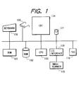
- Fig. 1 is a block diagram showing the basic arrangement of the virtual architecture experience apparatus according to the first embodiment of the present invention.
- a ROM 101 stores a program of the processing procedure.
- a RAM 102 stores information required for processing and input/output data.
- a CPU 103 executes processing in accordance with the stored program.
- a CRT 104 displays information required for processing and a 3D image.
- 3D vision spectacles 105 have a line of sight detection function of detecting the 3D position of the viewpoint of an observer with respect to the CRT 104 and the direction of line of sight.
- a keyboard 106 is used by a user to input data and instructions.
- a mouse 107 is used by the user to input instructions on the CRT 104.
- Image data is fetched from an image scanner 109 via an input/output (I/O) interface 108.
- a floppy disk (FD) as a storage medium is inserted into a floppy disk drive (FDD) 110.
- FDD floppy disk drive
- a drive for another storage media such as a hard disk, a magnetic tape, or the like may be used in place of the FDD 110.
- Data (3D geometric data, image data, and virtual space data) created by an external apparatus or another application program may be fetched via these storage media.
- the processing procedure includes virtual space generation processing for interactively generating virtual space data of an architecture on a computer, and virtual space experience processing for allowing an operator to interactively experience the virtual space on the computer using the computer graphics technique with respect to the virtual space data created in the generation processing, and the program writing this processing procedure is stored in the ROM 101.
- Fig. 2 shows the flow of the virtual space generation processing in the first embodiment.
- the arrows indicate the flow of processing.
- a plan of an architecture is stored in the RAM 102 as an image using the image scanner 109 (step S210).
- a picture of the interior of the architecture and a panorama image of the exterior landscape are stored as images in the RAM 102 using the image scanner 109 (step S220).
- step S230 3D geometric data of the architecture is generated by interactive operations with the user on the basis of the image of the plan of the architecture stored in the RAM 102. The 3D information generation processing will be described later with reference to Fig. 3.
- step S240 geometric data of furniture objects and the like created by another modelling software program are fetched from an FD into the RAM 102 via the FDD 110, and these objects are arranged in the 3D geometric data generated in step S230.
- step S250 an attribute indicating whether or not an object is movable is assigned to the respective objects in the 3D geometric data generated in the steps executed so far.
- step S260 the 3D geometric data generated in the steps executed so far are arranged in 3D geometric data representing the shape of the landscape.
- step S270 the user interactively designates the correspondences between feature points of the actually taken image of the interior of the architecture and the panorama image of the landscape, and the vertices in the 3D geometric data.
- a plurality of images can be mapped on a single primitive using the technique for associating the positions of points designated on a polygon image to the positions of points designated on an original texture image including required texture images (US Application No. 08/721,219 (EP Appln. No. 96307096)).
- the 3D geometric data and image mapping data are stored in the RAM 102 as virtual space data in the format shown in Fig. 4 (step S280). Upon completion of step S280, the virtual space generation processing ends.
- an "object” e.g., "living ⁇ dining room” or the like
- some “primitives” e.g., a portion such as "east wall” defined by one texture and surface attribute.
- Each primitive is defined by at last one plane, and each plane is defined by a triangle or rectangle patch.
- the 3D geometric data describes 3D data of vertices that define the patch, and the connection relationship of the vertices.
- the 3D geometric data clearly describes a flag indicating that it is movable, and the conditions for movement.
- the image mapping data describes the names of images corresponding to primitives, and the correspondences between the vertices in each primitive in the 3D geometric data and the positions on the corresponding image.
- step S230 The 3D information generation processing in step S230 will be described below with reference to Fig. 3.
- one plan image of the architecture object stored in the RAM 102 is displayed on the CRT 104 (step S310).
- the user then inputs the name of the displayed plan object (step S320) and designates the reduced scale of an actual size using the keyboard 106 (step S330). With this operation, the correspondence between the length of a segment on the image and the actual size can be obtained.
- Fig. 5 shows this state. 3D geometric data (primitives and patches) generated thereafter belong to this object.
- the user inputs the name of the primitive to be traced using the keyboard 106 (step S341).
- Fig. 6 shows this state.
- attributes as to the types (a normal wall, a wall with an opening for a door, and the like) of walls are set for all segments that connect the vertices (step S343).
- Step S343 is repeated until attributes are set for all the segments (step S344), and steps S341 to S344 are repeated until all the primitives are traced (step S345).
- steps S341 to S345 since primitives are designated using the segments on the plan, the shapes of only walls perpendicular to the plan are generated. Subsequently, floor and ceiling primitives parallel to the plan are generated in turn. The names of the floor and ceiling primitives to be generated are designated (step S351). The four corners appearing on the plan of the floor or ceiling are designated using the mouse 107 on the plan displayed on the CRT 104 (step S352). Finally, the heights of the floor and ceiling are input (step S353). Fig. 8 shows this state. Steps S351 to S353 are repeated until all the floor and ceiling areas are designated (step S354), and patches that define 3D geometric data are generated on the basis of these pieces of information (step S360).
- step S370 The objects are interactively arranged (step S380) to express 3D data of all the objects by a single coordinate system.
- the generated 3D information is stored in the RAM 102 in the format shown in Fig. 4 (step S390).
- Fig. 9 shows the flow of the virtual space experience processing in the first embodiment.
- virtual space data is drawn in correspondence with changes in viewpoint position and direction of line of sight, and at the same time, the virtual space data is changed and re-drawn in correspondence with an event from the user.
- the viewpoint position and direction, used upon generating a reflection are set to be predetermined values (step S610). If there are a plurality of images mapped on the primitives in the virtual space data stored in the RAM 102, an image registered as first data is selected as the object to be mapped.
- step S620 The reflection of the architecture to be observed from the set viewpoint position and direction is generated on the basis of the virtual space data stored in the RAM 102 using the computer graphics function of the graphic workstation, and the generated reflection is displayed on the CRT 104 (step S620). It is then checked based on the position and direction of the user's head with respect to the CRT 104 obtained from the 3D vision spectacles 105, input information from the keyboard 106, and information from the mouse 107 if the viewpoint position and direction have changed (step S630). If YES in step S630, the viewpoint position and direction are re-calculated (S660) to re-generate a reflection (step S620). On the other hand, if NO in step S630, the flow advances to step S640.
- step S640 When a plurality of images to be mapped are designated for one primitive of the 3D geometric data in the image mapping processing in step S240, it is checked in step S640 if the user has changed an image to be used in texture mapping by directing his or her line of sight on the primitive of interest on the reflection using the line of sight input device of the 3D vision spectacles 105, or by designating the primitive of interest on the reflection using the mouse 107. If YES in step S640, the mapping image is switched to an arbitrary image registered (step S670), and a reflection is generated again (step S620). On the other hand, if NO in step S640, the flow advances to step S650.
- step S650 When a given object in the 3D geometric data is designated as a movable object in the 3D information generation processing in step S230, it is checked in step S650 if the user has moved the object of interest by directing his or her line of sight on the object of interest on the reflection using the line of sight input device of the 3D vision spectacles 105 or by designating the object of interest on the reflection using the mouse 107, and then designating the moving amount using the mouse 107 or the keyboard 106. If YES in step S650, the new object layout is calculated (step S680), and a reflection is generated again (step S620). By repeating such processing operations, the user can see the reflection observed from an arbitrary position, and can observe it while switching textures in correspondence with instructions from the user.
- the image of the interior of the architecture and the panorama image of the exterior landscape are scanned using the image scanner 109 and are stored in the RAM 102 in step S220, and the correspondences between the feature points in these images and the vertices in the 3D geometric data are designated in step S240.
- an image database that stores images frequently used (e.g., images of all the types of wall papers in an architecture) in advance may be built on an FD to be inserted into the FDD 110, and an image selected from those in the image database may be used. In this manner, the procedure of inputting a picture can be eliminated.
- an image may be input from an external device or another application program via the FDD 110 in place of reading an image using the image scanner 109.
- an image may be input from an external device or another application program via the FDD 110 in place of reading an image using the image scanner 109.
- 3D geometric data may be input from an external device or another application program via the FDD 110 in place of generating 3D geometric data.
- one object is divided into a plurality of primitives (each primitive is defined by a plurality of patches), and textures are mapped in units of primitives.
- the concept of primitives may be abandoned, and textures may be mapped in units of patches.
- top-down modelling is made by dividing one object into a plurality of primitives (each primitive is defined by a plurality of patches), and dividing each primitive into patches.
- bottom-up modelling may be made. That is, a patch may be defined first, and a plurality of patches may be designated as a group to sequentially define one primitive, thereby designating all primitives. Subsequently, a plurality of primitives may be designated as a group to sequentially define one object, thereby defining all objects.
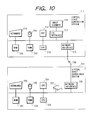
- Fig. 10 shows the basic arrangement of a virtual architecture experience apparatus according to the second embodiment of the present invention.
- a system 710 performs virtual space generation processing
- a system 720 performs virtual space experience processing.
- a ROM 711 stores a program writing the virtual space generation processing procedure.
- a RAM 712 stores information required for the processing and input/output data.
- a CPU 713 executes processing in accordance with the program stored in the ROM 711.
- a CRT 714 displays information required for the processing, and an image.
- a keyboard 715 is used by a user to input data and instructions.
- a mouse 716 is also used by the user to input instructions on the CRT 714.
- image data is fetched from an image scanner 718.
- a network interface 719 is connected to the virtual space experience system 720 via a network 730 such as Ethernet, ISDN, ATM, or the like.
- a ROM 721 stores a program writing the virtual space experience processing procedure.
- a RAM 722 stores information required for the processing and input/output data.
- a CPU 723 executes processing in accordance with the program stored in the ROM 721.
- a CRT 724 displays information required for the processing, and a 3D image.
- a keyboard 725 is used by a user to input data and instructions.
- a mouse 726 is also used by the user to input instructions on the CRT 724.
- 3D vision spectacles 727 have a line of sight input function of detecting the 3D position and the direction of line of sight of the viewpoint of the observer with respect to the CRT 724.
- a network interface 728 is connected to the virtual space generation system 710 via a network such as Ethernet, ISDN, ATM, or the like.
- virtual space data generated by the virtual space generation processing is stored in the RAM 102, and is shared by the virtual space experience processing.
- virtual space data generated by the virtual space generation processing is stored in the RAM 712 in the virtual space generation system 710.
- the virtual space data is transferred to the RAM 722 in the virtual space experience system 720 via the network interface 719, the network 730 such as Ethernet, ISDN, ATM, or the like, and the network interface 728 prior to the virtual space experience processing.
- the virtual space experience processing allows the operator to experience the virtual space using the virtual space data stored in the RAM 722 in the virtual space experience system 720.
- an operator B distant from an operator A assigned to the virtual space generation processing can experience the same virtual architecture as in the first embodiment with only the overhead of the time required for transferring virtual space data via the network.
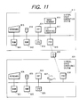
- Fig. 11 shows the basic arrangement of a virtual architecture experience apparatus according to the third embodiment of the present invention.
- a system 810 performs virtual space generation processing, and a system 820 performs virtual space experience processing.
- a ROM 811 stores a program writing the virtual space generation processing procedure.
- a RAM 812 stores information required for the processing and input/output data.
- a CPU 813 executes processing in accordance with the program stored in the ROM 811.
- a CRT 814 displays information required for the processing, and an image.
- a keyboard 815 is used by a user to input data and instructions.
- a mouse 816 is also used by the user to input instructions on the CRT 814.
- image data is fetched from an image scanner 818.
- An FDD 819 is a floppy disk drive.
- a ROM 821 stores a program writing the virtual space experience processing procedure.
- a RAM 822 stores information required for the processing and input/output data.
- a CPU 823 executes processing in accordance with the program stored in the ROM 821.
- a CRT 824 displays information required for the processing, and a 3D image.
- a keyboard 825 is used by a user to input data and instructions.
- a mouse 826 is also used by the user to input instructions on the CRT 824.
- 3D vision spectacles 827 have a line of sight input function of detecting the 3D position and the direction of line of sight of the viewpoint of the observer with respect to the CRT 824.
- An FDD 828 is a floppy disk drive as in the FDD 819.
- An FD 830 is a floppy disk that stores data via the FDD 819 in the virtual space generation system 810 or the FDD 828 in the virtual space experience system 820.
- virtual space data generated by the virtual space generation processing is stored in the RAM 102, and is shared by the virtual space experience processing.
- virtual space data generated by the virtual space generation processing is stored in the RAM 812 in the virtual space generation system 810.
- the virtual space data Prior to the virtual space experience processing, the virtual space data is stored in the FD 830 via the FDD 819.
- the user carries the FD 830 to the location of the virtual space experience system 820, and stores the virtual space data stored in the FD 830 in the RAM 822 in the virtual space experience system 820 via the FDD 828.
- the virtual space experience processing allows the operator to experience the virtual space using the virtual space data stored in the RAM 822 in the virtual space experience system 820.
- an operator B distant from an operator A assigned to the virtual space generation processing can experience the same virtual architecture as in the first embodiment.
- the user can easily generate a virtual space of an existing architecture, and can virtually experience the generated virtual space of the architecture as if he or she were observing an actual object.
Abstract
Description
- The present invention relates to a virtual architecture method and apparatus, which can provide images with high reality in correspondence with the requirements of a user.
- As a virtual space presentation apparatus with which a user can see a virtual space stored as data in a computer in accordance with the movement of his or her line of sight as he or she observes a real object, various types of apparatuses such as EyePhones (available from VPL Research Inc.) and the like have been developed. Applications of such technique to the housing industry have been examined. For example, a "Virtual Kitchen" system developed by Matsushita Electric Works Ltd. allows a customer to virtually experience the interior of a room and system kitchen provided by the manufacturer, and is used as an instrument of sales promotion.
- However, the above-mentioned prior arts do not consider a framework that can easily create a virtual space with high reality, and creating the virtual space requires much labor. Accordingly, the existing systems allow users to only experience virtual spaces provided by information providers. As a consequence, it is difficult to easily create a virtual space in an existing architecture owned by a customer like in re-form simulation of an architecture and to allow the customer to interactively experience the virtual space by means of reflections with high reality.
- It is an object of one aspect of the invention to provide a virtual architecture method and apparatus, which can solve the above-mentioned problems, and allow a user to easily create a virtual space of an architecture and to virtually experience the created virtual space.
- A virtual architecture method of one aspect of the present invention comprises: the virtual space generation step of generating virtual space data of an architecture on the basis of an instruction of an operator; and the virtual space display step of displaying the virtual space data generated in the virtual space generation step on the basis of an instruction of the operator.
- Also, a virtual architecture apparatus of another aspect of the present invention comprises: virtual space generation means for generating virtual space data of an architecture on the basis of an instruction of an operator; and virtual space display means for displaying the virtual space data generated by the virtual space generation means on the basis of an instruction of the operator.
- Embodiments of the present invention will now be described with reference to the accompanying drawings, in which:
- Fig. 1 is a block diagram showing the arrangement of a virtual architecture experience apparatus according to the first embodiment of the present invention;
- Fig. 2 is a flow chart showing the virtual space generation processing of the virtual architecture experience apparatus of the first embodiment;
- Fig. 3 is a flow chart showing the three-dimensional (3D) information generation processing of the virtual architecture experience apparatus of the first embodiment;
- Fig. 4 is a flow chart showing the format of virtual space data of the virtual architecture experience apparatus of the first embodiment;
- Fig. 5 illustrates an example of the screen display of the 3D information generation processing of the virtual architecture experience apparatus of the first embodiment;
- Fig. 6 illustrates an example of the screen display of the 3D information generation processing of the virtual architecture experience apparatus of the first embodiment;
- Fig. 7 illustrates an example of the screen display of the 3D information generation processing of the virtual architecture experience apparatus of the first embodiment;
- Fig. 8 illustrates an example of the screen display of the 3D information generation processing of the virtual architecture experience apparatus of the first embodiment;
- Fig. 9 is a flow chart showing the virtual space experience processing of the virtual architecture experience apparatus of the first embodiment;
- Fig. 10 is a block diagram showing the arrangement of a virtual architecture experience apparatus according to the second embodiment of the present invention; and
- Fig. 11 is a block diagram showing the arrangement of a virtual architecture experience apparatus according to the third embodiment of the present invention.
- In a virtual architecture apparatus of the first embodiment, a plan of an existing architecture, a picture of the interior of the architecture, and a panorama picture of the landscape taken at the terrace are prepared. The panorama picture is obtained by image processing for acquiring a field angle wider than that determined by a photographing device and can be created by a technique described in, e.g., US Application No. 08/597,699 (EP Appln. No. 96300782) filed by the present applicant. The plan of the architecture is then input as an image to the apparatus. A user traces, e.g., walls in the input image using a mouse or tablet to give information of the sizes, heights, shapes, and the like to them, thereby generating three-dimensional (3D) geometric data of the architecture. If the plan of the architecture is not available, 3D geometric data of the architecture created by another 3D modelling software program may be used. The 3D geometric data of the architecture is arranged in a cylindrical space that represents the surrounding landscape. Then, the actually taken image of the interior of the architecture and the panorama image of the landscape are input to the apparatus. The input images are subjected to conversion of colors and gradation, correction of geometric distortion, and the like by a separately prepared image edit program (e.g., PhotoShop available from Adobe Systems Inc.) if necessary. Mapping of feature points in the images to the corresponding vertices of 3D geometric data is interactively designated. In this mapping technique, for example, a technique for associating the positions of points designated on a polygon image to the positions of points designated on an original texture image including required texture images may be used (US Application No. 08/721,219 (EP Appln. No. 96307096)). With this mapping, the correspondences between the vertices in the 3D geometric data and the positions in each image can be designated. The created 3D geometric data and image mapping data are stored as virtual space data.
- On the other hand, upon experiencing the virtual space, the stored virtual space data are loaded, and a 3D space reflection is presented on a graphic workstation (e.g., IRIS Crimson with Reality Engine; available from Silicon Graphics Inc. (SGI)) using a computer graphics technique. At this time, in addition to projection of 3D geometric data onto the reflection, images designated as the image mapping data are texture-mapped on the 3D geometric data, thereby presenting the reflection with high reality. Also, an image for 3D vision is presented, and a reflection which changes in real time in response to interactive operations by an operator for moving the viewpoint/line of sight, furniture, and the like, or changing images used for texture mapping is presented, thus providing virtual experience with reality.
- Fig. 1 is a block diagram showing the basic arrangement of the virtual architecture experience apparatus according to the first embodiment of the present invention. In Fig. 1, a
ROM 101 stores a program of the processing procedure. ARAM 102 stores information required for processing and input/output data. ACPU 103 executes processing in accordance with the stored program. ACRT 104 displays information required for processing and a 3D image.3D vision spectacles 105 have a line of sight detection function of detecting the 3D position of the viewpoint of an observer with respect to theCRT 104 and the direction of line of sight. Akeyboard 106 is used by a user to input data and instructions. Amouse 107 is used by the user to input instructions on the CRT 104. Image data is fetched from animage scanner 109 via an input/output (I/O)interface 108. A floppy disk (FD) as a storage medium is inserted into a floppy disk drive (FDD) 110. Note that a drive for another storage media such as a hard disk, a magnetic tape, or the like may be used in place of the FDD 110. Data (3D geometric data, image data, and virtual space data) created by an external apparatus or another application program may be fetched via these storage media. - In the first embodiment, the processing procedure includes virtual space generation processing for interactively generating virtual space data of an architecture on a computer, and virtual space experience processing for allowing an operator to interactively experience the virtual space on the computer using the computer graphics technique with respect to the virtual space data created in the generation processing, and the program writing this processing procedure is stored in the
ROM 101. - Fig. 2 shows the flow of the virtual space generation processing in the first embodiment. In Fig. 2, the arrows indicate the flow of processing. In the first embodiment, a plan of an architecture is stored in the
RAM 102 as an image using the image scanner 109 (step S210). Also, a picture of the interior of the architecture and a panorama image of the exterior landscape are stored as images in theRAM 102 using the image scanner 109 (step S220). In step S230, 3D geometric data of the architecture is generated by interactive operations with the user on the basis of the image of the plan of the architecture stored in theRAM 102. The 3D information generation processing will be described later with reference to Fig. 3. In step S240, geometric data of furniture objects and the like created by another modelling software program are fetched from an FD into theRAM 102 via the FDD 110, and these objects are arranged in the 3D geometric data generated in step S230. In step S250, an attribute indicating whether or not an object is movable is assigned to the respective objects in the 3D geometric data generated in the steps executed so far. In step S260, the 3D geometric data generated in the steps executed so far are arranged in 3D geometric data representing the shape of the landscape. In step S270, the user interactively designates the correspondences between feature points of the actually taken image of the interior of the architecture and the panorama image of the landscape, and the vertices in the 3D geometric data. In this image mapping processing, a plurality of images can be mapped on a single primitive using the technique for associating the positions of points designated on a polygon image to the positions of points designated on an original texture image including required texture images (US Application No. 08/721,219 (EP Appln. No. 96307096)). The 3D geometric data and image mapping data are stored in theRAM 102 as virtual space data in the format shown in Fig. 4 (step S280). Upon completion of step S280, the virtual space generation processing ends. - In the data shown in Fig. 4, an "object" (e.g., "living·dining room" or the like) that realizes one function is defined by some "primitives" (e.g., a portion such as "east wall" defined by one texture and surface attribute). Each primitive is defined by at last one plane, and each plane is defined by a triangle or rectangle patch. For each patch, the 3D geometric data describes 3D data of vertices that define the patch, and the connection relationship of the vertices. For an object designated as a movable object in the 3D information generation processing in step S230, the 3D geometric data clearly describes a flag indicating that it is movable, and the conditions for movement. The image mapping data describes the names of images corresponding to primitives, and the correspondences between the vertices in each primitive in the 3D geometric data and the positions on the corresponding image.
- The 3D information generation processing in step S230 will be described below with reference to Fig. 3. In the 3D information generation processing, one plan image of the architecture object stored in the
RAM 102 is displayed on the CRT 104 (step S310). The user then inputs the name of the displayed plan object (step S320) and designates the reduced scale of an actual size using the keyboard 106 (step S330). With this operation, the correspondence between the length of a segment on the image and the actual size can be obtained. Fig. 5 shows this state. 3D geometric data (primitives and patches) generated thereafter belong to this object. The user inputs the name of the primitive to be traced using the keyboard 106 (step S341). Then, the user designates points on the image corresponding to the vertices of the primitive using themouse 107, thereby tracing the primitive appearing on the plan (step S342). Fig. 6 shows this state. As shown in Fig. 7, attributes as to the types (a normal wall, a wall with an opening for a door, and the like) of walls are set for all segments that connect the vertices (step S343). Step S343 is repeated until attributes are set for all the segments (step S344), and steps S341 to S344 are repeated until all the primitives are traced (step S345). - In steps S341 to S345, since primitives are designated using the segments on the plan, the shapes of only walls perpendicular to the plan are generated. Subsequently, floor and ceiling primitives parallel to the plan are generated in turn. The names of the floor and ceiling primitives to be generated are designated (step S351). The four corners appearing on the plan of the floor or ceiling are designated using the
mouse 107 on the plan displayed on the CRT 104 (step S352). Finally, the heights of the floor and ceiling are input (step S353). Fig. 8 shows this state. Steps S351 to S353 are repeated until all the floor and ceiling areas are designated (step S354), and patches that define 3D geometric data are generated on the basis of these pieces of information (step S360). These processing operations are repeated for all the objects included in the architecture (step S370). The objects are interactively arranged (step S380) to express 3D data of all the objects by a single coordinate system. The generated 3D information is stored in theRAM 102 in the format shown in Fig. 4 (step S390). - On the other hand, Fig. 9 shows the flow of the virtual space experience processing in the first embodiment. As in the flow of the processing of a normal virtual experience system, virtual space data is drawn in correspondence with changes in viewpoint position and direction of line of sight, and at the same time, the virtual space data is changed and re-drawn in correspondence with an event from the user. In the first embodiment, the viewpoint position and direction, used upon generating a reflection, are set to be predetermined values (step S610). If there are a plurality of images mapped on the primitives in the virtual space data stored in the
RAM 102, an image registered as first data is selected as the object to be mapped. The reflection of the architecture to be observed from the set viewpoint position and direction is generated on the basis of the virtual space data stored in theRAM 102 using the computer graphics function of the graphic workstation, and the generated reflection is displayed on the CRT 104 (step S620). It is then checked based on the position and direction of the user's head with respect to theCRT 104 obtained from the3D vision spectacles 105, input information from thekeyboard 106, and information from themouse 107 if the viewpoint position and direction have changed (step S630). If YES in step S630, the viewpoint position and direction are re-calculated (S660) to re-generate a reflection (step S620). On the other hand, if NO in step S630, the flow advances to step S640. - When a plurality of images to be mapped are designated for one primitive of the 3D geometric data in the image mapping processing in step S240, it is checked in step S640 if the user has changed an image to be used in texture mapping by directing his or her line of sight on the primitive of interest on the reflection using the line of sight input device of the
3D vision spectacles 105, or by designating the primitive of interest on the reflection using themouse 107. If YES in step S640, the mapping image is switched to an arbitrary image registered (step S670), and a reflection is generated again (step S620). On the other hand, if NO in step S640, the flow advances to step S650. When a given object in the 3D geometric data is designated as a movable object in the 3D information generation processing in step S230, it is checked in step S650 if the user has moved the object of interest by directing his or her line of sight on the object of interest on the reflection using the line of sight input device of the3D vision spectacles 105 or by designating the object of interest on the reflection using themouse 107, and then designating the moving amount using themouse 107 or thekeyboard 106. If YES in step S650, the new object layout is calculated (step S680), and a reflection is generated again (step S620). By repeating such processing operations, the user can see the reflection observed from an arbitrary position, and can observe it while switching textures in correspondence with instructions from the user. - In the first embodiment, the image of the interior of the architecture and the panorama image of the exterior landscape are scanned using the
image scanner 109 and are stored in theRAM 102 in step S220, and the correspondences between the feature points in these images and the vertices in the 3D geometric data are designated in step S240. However, in addition to images input from the scanner, an image database that stores images frequently used (e.g., images of all the types of wall papers in an architecture) in advance may be built on an FD to be inserted into theFDD 110, and an image selected from those in the image database may be used. In this manner, the procedure of inputting a picture can be eliminated. - In step S210 in the first embodiment, an image may be input from an external device or another application program via the
FDD 110 in place of reading an image using theimage scanner 109. - In step S220 in the first embodiment, an image may be input from an external device or another application program via the
FDD 110 in place of reading an image using theimage scanner 109. - In step S230 in the first embodiment, 3D geometric data may be input from an external device or another application program via the
FDD 110 in place of generating 3D geometric data. - In the first embodiment, as shown in Fig. 4, one object is divided into a plurality of primitives (each primitive is defined by a plurality of patches), and textures are mapped in units of primitives.
- Alternatively, the concept of primitives may be abandoned, and textures may be mapped in units of patches.
- In the first embodiment, as shown in Fig. 3, top-down modelling is made by dividing one object into a plurality of primitives (each primitive is defined by a plurality of patches), and dividing each primitive into patches. Alternatively, bottom-up modelling may be made. That is, a patch may be defined first, and a plurality of patches may be designated as a group to sequentially define one primitive, thereby designating all primitives. Subsequently, a plurality of primitives may be designated as a group to sequentially define one object, thereby defining all objects.
- Fig. 10 shows the basic arrangement of a virtual architecture experience apparatus according to the second embodiment of the present invention. Referring to Fig. 10, a
system 710 performs virtual space generation processing, and asystem 720 performs virtual space experience processing. In the virtualspace generation system 710, aROM 711 stores a program writing the virtual space generation processing procedure. ARAM 712 stores information required for the processing and input/output data. ACPU 713 executes processing in accordance with the program stored in theROM 711. ACRT 714 displays information required for the processing, and an image. Akeyboard 715 is used by a user to input data and instructions. Amouse 716 is also used by the user to input instructions on theCRT 714. Via an I/O interface 717, image data is fetched from animage scanner 718. Anetwork interface 719 is connected to the virtualspace experience system 720 via anetwork 730 such as Ethernet, ISDN, ATM, or the like. In the virtualspace experience system 720, aROM 721 stores a program writing the virtual space experience processing procedure. ARAM 722 stores information required for the processing and input/output data. ACPU 723 executes processing in accordance with the program stored in theROM 721. ACRT 724 displays information required for the processing, and a 3D image. Akeyboard 725 is used by a user to input data and instructions. Amouse 726 is also used by the user to input instructions on theCRT 724.3D vision spectacles 727 have a line of sight input function of detecting the 3D position and the direction of line of sight of the viewpoint of the observer with respect to theCRT 724. A network interface 728 is connected to the virtualspace generation system 710 via a network such as Ethernet, ISDN, ATM, or the like. - The processing procedures are the same as those in the first embodiment. However, in the first embodiment, virtual space data generated by the virtual space generation processing is stored in the
RAM 102, and is shared by the virtual space experience processing. In the second embodiment, virtual space data generated by the virtual space generation processing is stored in theRAM 712 in the virtualspace generation system 710. The virtual space data is transferred to theRAM 722 in the virtualspace experience system 720 via thenetwork interface 719, thenetwork 730 such as Ethernet, ISDN, ATM, or the like, and the network interface 728 prior to the virtual space experience processing. Thereafter, the virtual space experience processing allows the operator to experience the virtual space using the virtual space data stored in theRAM 722 in the virtualspace experience system 720. - With this system, an operator B distant from an operator A assigned to the virtual space generation processing can experience the same virtual architecture as in the first embodiment with only the overhead of the time required for transferring virtual space data via the network.
- Fig. 11 shows the basic arrangement of a virtual architecture experience apparatus according to the third embodiment of the present invention. Referring to Fig. 11, a
system 810 performs virtual space generation processing, and asystem 820 performs virtual space experience processing. In the virtualspace generation system 810, aROM 811 stores a program writing the virtual space generation processing procedure. ARAM 812 stores information required for the processing and input/output data. ACPU 813 executes processing in accordance with the program stored in theROM 811. ACRT 814 displays information required for the processing, and an image. Akeyboard 815 is used by a user to input data and instructions. Amouse 816 is also used by the user to input instructions on theCRT 814. Via an I/O interface 817, image data is fetched from animage scanner 818. AnFDD 819 is a floppy disk drive. In the virtualspace experience system 820, aROM 821 stores a program writing the virtual space experience processing procedure. ARAM 822 stores information required for the processing and input/output data. ACPU 823 executes processing in accordance with the program stored in theROM 821. ACRT 824 displays information required for the processing, and a 3D image. Akeyboard 825 is used by a user to input data and instructions. Amouse 826 is also used by the user to input instructions on theCRT 824.3D vision spectacles 827 have a line of sight input function of detecting the 3D position and the direction of line of sight of the viewpoint of the observer with respect to theCRT 824. AnFDD 828 is a floppy disk drive as in theFDD 819. AnFD 830 is a floppy disk that stores data via theFDD 819 in the virtualspace generation system 810 or theFDD 828 in the virtualspace experience system 820. - The processing procedures are the same as those in the first embodiment. However, in the first embodiment, virtual space data generated by the virtual space generation processing is stored in the
RAM 102, and is shared by the virtual space experience processing. In the third embodiment, virtual space data generated by the virtual space generation processing is stored in theRAM 812 in the virtualspace generation system 810. Prior to the virtual space experience processing, the virtual space data is stored in theFD 830 via theFDD 819. The user carries theFD 830 to the location of the virtualspace experience system 820, and stores the virtual space data stored in theFD 830 in theRAM 822 in the virtualspace experience system 820 via theFDD 828.
Thereafter, the virtual space experience processing allows the operator to experience the virtual space using the virtual space data stored in theRAM 822 in the virtualspace experience system 820. - With this system, an operator B distant from an operator A assigned to the virtual space generation processing can experience the same virtual architecture as in the first embodiment.
- As described above, the user can easily generate a virtual space of an existing architecture, and can virtually experience the generated virtual space of the architecture as if he or she were observing an actual object.
Claims (26)
- A virtual architecture method comprising:the virtual space generation step of generating virtual space data of an architecture on the basis of an instruction of an operator; andthe virtual space display step of displaying the virtual space data generated in the virtual space generation step on the basis of an instruction of the operator.
- A method according to claim 1, wherein the virtual space generation step comprises the three-dimensional information generation step of generating three-dimensional geometric data of the architecture, and the image mapping step of generating image mapping data by mapping textures representing surface patterns onto individual portions of the three-dimensional geometric data generated in the three-dimensional information generation step, the virtual space data including the three-dimensional geometric data and the image mapping data.
- A method according to claim 2, wherein the three-dimensional information generation step includes the step of generating the three-dimensional geometric data on the basis of a plan of the architecture, and height information including a height of a ceiling.
- A method according to claim 2, wherein the three-dimensional information generation step includes the step of arranging the three-dimensional geometric data of the architecture at a center of a landscape space representing an exterior landscape of the architecture.
- A method according to claim 2, wherein the three-dimensional information generation step includes the step of reading and using three-dimensional geometric data of the architecture generated by another application program.
- A method according to claim 2, wherein the three-dimensional information generation step includes the step of reading three-dimensional geometric data of interior objects of the architecture generated by another application program, and arranging the three-dimensional geometric data inside the architecture.
- A method according to claim 2, wherein the image mapping step includes the step of mapping actually taken pictures of an interior of the architecture onto corresponding portions in the three-dimensional geometric data.
- A method according to claim 2, wherein the image mapping step includes the step of mapping an actually taken picture of a landscape onto the landscape space representing the exterior landscape of the architecture.
- A method according to claim 2, wherein the image mapping step includes the step of mapping a plurality of textures onto an identical portion of the three-dimensional geometric data.
- A method according to claim 2, wherein the virtual space display step includes the step of generating a reflection on the basis of the three-dimensional geometric data and the image mapping data of the virtual space data generated in the virtual space generation step, and changing displayed contents in correspondence with movement of a viewpoint and/or a line of sight of the operator.
- A method according to claim 2, wherein the virtual space display step includes the step of generating a reflection by switching a plurality of textures mapped on an identical portion in the three-dimensional geometric data generated in the virtual space generation step on the basis of an instruction of the operator.
- A method according to claim 2, wherein the virtual space display step includes the step of generating a reflection by moving three-dimensional geometric data of an interior object arranged inside the architecture generated in the virtual space generation step on the basis of an instruction of the operator.
- A virtual architecture apparatus comprising:virtual space generation means for generating virtual space data of an architecture on the basis of an instruction of an operator; andvirtual space display means for displaying the virtual space data generated by said virtual space generation means on the basis of an instruction of the operator.
- An apparatus according to claim 13, wherein said virtual space generation means comprises three-dimensional information generation means for generating three-dimensional geometric data of the architecture, and image mapping means for generating image mapping data by mapping textures representing surface patterns onto individual portions of the three-dimensional geometric data generated by said three-dimensional information generation means, the virtual space data including the three-dimensional geometric data and the image mapping data.
- An apparatus according to claim 14, wherein said three-dimensional information generation means generates the three-dimensional geometric data on the basis of a plan of the architecture, and height information including a height of a ceiling.
- An apparatus according to claim 14, wherein said three-dimensional information generation means arranges the three-dimensional geometric data of the architecture at a center of a landscape space representing an exterior landscape of the architecture.
- An apparatus according to claim 14, wherein said three-dimensional information generation means reads and uses three-dimensional geometric data of the architecture generated by another application program.
- An apparatus according to claim 14, wherein said three-dimensional information generation means reads three-dimensional geometric data of interior objects of the architecture generated by another application program, and arranges the three-dimensional geometric data inside the architecture.
- An apparatus according to claim 14, wherein said image mapping means maps actually taken pictures of an interior of the architecture onto corresponding portions in the three-dimensional geometric data.
- An apparatus according to claim 14, wherein said image mapping means maps an actually taken picture of a landscape onto the landscape space representing the exterior landscape of the architecture.
- An apparatus according to claim 14, wherein said image mapping means maps a plurality of textures onto an identical portion of the three-dimensional geometric data.
- An apparatus according to claim 14, wherein said virtual space display means generates a reflection on the basis of the three-dimensional geometric data and the image mapping data of the virtual space data generated by said virtual space generation means, and changes displayed contents in correspondence with movement of a viewpoint and/or a line of sight of the operator.
- An apparatus according to claim 14, wherein said virtual space display means generates a reflection by switching a plurality of textures mapped on an identical portion in the three-dimensional geometric data generated by said virtual space generation means on the basis of an instruction of the operator.
- An apparatus according to claim 14, wherein said virtual space display means generates a reflection by moving three-dimensional geometric data of an interior object arranged inside the architecture generated by said virtual space generation means on the basis of an instruction of the operator.
- A storage medium which stores a computer program for realizing a virtual architecture experience method, which comprises:the virtual space generation step of generating virtual space data of an architecture on the basis of an instruction of an operator; andthe virtual space display step of displaying the virtual space data generated in the virtual space generation step on the basis of an instruction of the operator.
- Virtual reality apparatus for generating and displaying a virtual reality image of a structure, the apparatus comprising:user operable input means for inputting instructions;virtual space generating means for generating virtual reality space data for a structure in response to said user operable input means, wherein said virtual space generating means is adapted to be responsive to said user operable input means to assign three dimensional geometric data to features in the virtual reality domain, and to map textures representing surface patterns onto the features; anddisplay means for displaying the virtual reality space data in dependence upon a viewing position in the virtual reality domain.
Applications Claiming Priority (2)
| Application Number | Priority Date | Filing Date | Title |
|---|---|---|---|
| JP47245/96 | 1996-03-05 | ||
| JP4724596A JPH09244522A (en) | 1996-03-05 | 1996-03-05 | Method and device for undergoing virtual building |
Publications (3)
| Publication Number | Publication Date |
|---|---|
| EP0794517A2 true EP0794517A2 (en) | 1997-09-10 |
| EP0794517A3 EP0794517A3 (en) | 1998-10-21 |
| EP0794517B1 EP0794517B1 (en) | 2006-02-01 |
Family
ID=12769862
Family Applications (1)
| Application Number | Title | Priority Date | Filing Date |
|---|---|---|---|
| EP97301413A Expired - Lifetime EP0794517B1 (en) | 1996-03-05 | 1997-03-04 | Virtual architecture method and apparatus |
Country Status (4)
| Country | Link |
|---|---|
| US (1) | US6683606B1 (en) |
| EP (1) | EP0794517B1 (en) |
| JP (1) | JPH09244522A (en) |
| DE (1) | DE69735181T2 (en) |
Cited By (11)
| Publication number | Priority date | Publication date | Assignee | Title |
|---|---|---|---|---|
| WO1998047106A1 (en) * | 1997-04-16 | 1998-10-22 | British Telecommunications Public Limited Company | Display terminal |
| WO2001039119A2 (en) * | 1999-11-23 | 2001-05-31 | Canon Kabushiki Kaisha | Image processing apparatus |
| NL1014386C2 (en) * | 2000-02-15 | 2001-08-16 | Dipro B V | Three dimensional computerized design system for rooms, gardens, etc., uses manipulatable images of objects, textiles, etc., downloaded from remote computers via internet |
| WO2001093202A2 (en) * | 2000-06-01 | 2001-12-06 | Imperial Chemical Industries Plc | Colour visualisation system |
| US6452905B1 (en) | 1995-03-08 | 2002-09-17 | British Telecommunications Public Limited Company | Broadband switching system |
| US7054794B2 (en) | 2000-06-01 | 2006-05-30 | Richard David Brunt | Color visualisation system |
| US7079679B2 (en) | 2000-09-27 | 2006-07-18 | Canon Kabushiki Kaisha | Image processing apparatus |
| US7492476B1 (en) | 1999-11-23 | 2009-02-17 | Canon Kabushiki Kaisha | Image processing apparatus |
| WO2009044189A1 (en) * | 2007-09-29 | 2009-04-09 | Articad Ltd | Methods and apparatus for creating customisable cad image files |
| US7620234B2 (en) | 2000-10-06 | 2009-11-17 | Canon Kabushiki Kaisha | Image processing apparatus and method for generating a three-dimensional model of an object from a collection of images of the object recorded at different viewpoints and segmented using semi-automatic segmentation techniques |
| EP2204776A1 (en) * | 2007-11-01 | 2010-07-07 | Konami Digital Entertainment Co., Ltd. | Image processing device, image processing method, information recording medium and program |
Families Citing this family (11)
| Publication number | Priority date | Publication date | Assignee | Title |
|---|---|---|---|---|
| US20020154132A1 (en) * | 1997-07-30 | 2002-10-24 | Alain M. Dumesny | Texture mapping 3d graphic objects |
| JP4119529B2 (en) | 1998-06-17 | 2008-07-16 | オリンパス株式会社 | Virtual environment generation method and apparatus, and recording medium on which virtual environment generation program is recorded |
| JP2001297182A (en) * | 2000-04-14 | 2001-10-26 | Matsushita Electric Works Ltd | Business support system for house, which uses communication web |
| US20060036513A1 (en) * | 2001-09-26 | 2006-02-16 | Jerry Whatley | System and method for providing property improvements |
| US7869981B2 (en) | 2004-11-19 | 2011-01-11 | Edgenet, Inc. | Automated method and system for object configuration |
| WO2006054992A1 (en) * | 2004-11-19 | 2006-05-26 | Edgenet, Inc. | Automated method and system for object configuration |
| WO2007005072A1 (en) * | 2005-06-29 | 2007-01-11 | William Parrish | Site plan tool |
| JP2012073667A (en) * | 2010-09-27 | 2012-04-12 | Hiroyuki Miyakami | Display system |
| CN104268944A (en) * | 2014-09-09 | 2015-01-07 | 北京尔宜居科技有限责任公司 | Automatic display method of decorative tile and marble laying scheme |
| JP6727388B1 (en) * | 2019-11-28 | 2020-07-22 | 株式会社ドワンゴ | Class system, viewing terminal, information processing method and program |
| KR102399248B1 (en) * | 2021-10-15 | 2022-05-19 | 주식회사 에르사츠 | Apparatus, method and computer-readable storage medium for generating digital twin space based on architectural drawing |
Citations (6)
| Publication number | Priority date | Publication date | Assignee | Title |
|---|---|---|---|---|
| US4645459A (en) * | 1982-07-30 | 1987-02-24 | Honeywell Inc. | Computer generated synthesized imagery |
| US4970666A (en) * | 1988-03-30 | 1990-11-13 | Land Development Laboratory, Inc. | Computerized video imaging system for creating a realistic depiction of a simulated object in an actual environment |
| WO1992009963A1 (en) * | 1990-11-30 | 1992-06-11 | Vpl Research, Inc. | System for creating a virtual world |
| FR2702291A1 (en) * | 1993-03-05 | 1994-09-09 | Guillemin Jean Pierre | Method for simulating repetitive patterns on a digitized image, application to the production of an interactive video catalog and resulting catalog. |
| EP0633549A2 (en) * | 1993-07-02 | 1995-01-11 | Matsushita Electric Industrial Co., Ltd. | Simulator for producing various living environments mainly for visual perception |
| US5467444A (en) * | 1990-11-07 | 1995-11-14 | Hitachi, Ltd. | Method of three-dimensional display of object-oriented figure information and system thereof |
Family Cites Families (2)
| Publication number | Priority date | Publication date | Assignee | Title |
|---|---|---|---|---|
| US5602564A (en) * | 1991-11-14 | 1997-02-11 | Hitachi, Ltd. | Graphic data processing system |
| US5555354A (en) * | 1993-03-23 | 1996-09-10 | Silicon Graphics Inc. | Method and apparatus for navigation within three-dimensional information landscape |
-
1996
- 1996-03-05 JP JP4724596A patent/JPH09244522A/en active Pending
-
1997
- 1997-02-28 US US08/808,899 patent/US6683606B1/en not_active Expired - Lifetime
- 1997-03-04 DE DE69735181T patent/DE69735181T2/en not_active Expired - Lifetime
- 1997-03-04 EP EP97301413A patent/EP0794517B1/en not_active Expired - Lifetime
Patent Citations (6)
| Publication number | Priority date | Publication date | Assignee | Title |
|---|---|---|---|---|
| US4645459A (en) * | 1982-07-30 | 1987-02-24 | Honeywell Inc. | Computer generated synthesized imagery |
| US4970666A (en) * | 1988-03-30 | 1990-11-13 | Land Development Laboratory, Inc. | Computerized video imaging system for creating a realistic depiction of a simulated object in an actual environment |
| US5467444A (en) * | 1990-11-07 | 1995-11-14 | Hitachi, Ltd. | Method of three-dimensional display of object-oriented figure information and system thereof |
| WO1992009963A1 (en) * | 1990-11-30 | 1992-06-11 | Vpl Research, Inc. | System for creating a virtual world |
| FR2702291A1 (en) * | 1993-03-05 | 1994-09-09 | Guillemin Jean Pierre | Method for simulating repetitive patterns on a digitized image, application to the production of an interactive video catalog and resulting catalog. |
| EP0633549A2 (en) * | 1993-07-02 | 1995-01-11 | Matsushita Electric Industrial Co., Ltd. | Simulator for producing various living environments mainly for visual perception |
Non-Patent Citations (3)
| Title |
|---|
| JACOBSON R: "Virtual worlds: a new type of design environment" VIRTUAL REALITY WORLD, MAY-JUNE 1994, USA, vol. 2, no. 3, pages 46-52, XP002075174 ISSN 1060-9547 * |
| LOCKLEY S R ET AL: "The development of a design tool" ADAPTIVE INTELLIGENT ENERGY SYSTEMS CONFERENCE, BRUSSELS, BELGIUM, FEB. 1993, vol. 28, no. 10, pages 1499-1506, XP002075026 ISSN 0031-3203, Pattern Recognition, Oct. 1995, UK * |
| PLUMMER M ET AL: "Mass market applications for real-time 3D graphics" 7TH EUROGRAPHICS UK CONFERENCE, MANCHESTER, UK, 29-31 MARCH 1989, vol. 8, no. 2, pages 143-150, XP002075173 ISSN 0167-7055, Computer Graphics Forum, June 1989, Netherlands * |
Cited By (19)
| Publication number | Priority date | Publication date | Assignee | Title |
|---|---|---|---|---|
| US6452905B1 (en) | 1995-03-08 | 2002-09-17 | British Telecommunications Public Limited Company | Broadband switching system |
| US6331858B2 (en) | 1997-04-16 | 2001-12-18 | British Telecommunications Public Limited Company | Display terminal user interface with ability to select remotely stored surface finish for mapping onto displayed 3-D surface |
| WO1998047106A1 (en) * | 1997-04-16 | 1998-10-22 | British Telecommunications Public Limited Company | Display terminal |
| WO2001039119A2 (en) * | 1999-11-23 | 2001-05-31 | Canon Kabushiki Kaisha | Image processing apparatus |
| US7492476B1 (en) | 1999-11-23 | 2009-02-17 | Canon Kabushiki Kaisha | Image processing apparatus |
| WO2001039119A3 (en) * | 1999-11-23 | 2002-05-10 | Canon Kk | Image processing apparatus |
| NL1014386C2 (en) * | 2000-02-15 | 2001-08-16 | Dipro B V | Three dimensional computerized design system for rooms, gardens, etc., uses manipulatable images of objects, textiles, etc., downloaded from remote computers via internet |
| US7054794B2 (en) | 2000-06-01 | 2006-05-30 | Richard David Brunt | Color visualisation system |
| WO2001093202A3 (en) * | 2000-06-01 | 2002-03-21 | Ici Plc | Colour visualisation system |
| US7069193B2 (en) | 2000-06-01 | 2006-06-27 | Richard David Brunt | Color visualization system |
| WO2001093202A2 (en) * | 2000-06-01 | 2001-12-06 | Imperial Chemical Industries Plc | Colour visualisation system |
| US7079679B2 (en) | 2000-09-27 | 2006-07-18 | Canon Kabushiki Kaisha | Image processing apparatus |
| US7620234B2 (en) | 2000-10-06 | 2009-11-17 | Canon Kabushiki Kaisha | Image processing apparatus and method for generating a three-dimensional model of an object from a collection of images of the object recorded at different viewpoints and segmented using semi-automatic segmentation techniques |
| WO2009044189A1 (en) * | 2007-09-29 | 2009-04-09 | Articad Ltd | Methods and apparatus for creating customisable cad image files |
| GB2453528A (en) * | 2007-09-29 | 2009-04-15 | Articad Ltd | Creating Customisable CAD Image Files |
| GB2453528B (en) * | 2007-09-29 | 2010-03-03 | Articad Ltd | Methods and apparatus for creating customisable cad images |
| EP2204776A1 (en) * | 2007-11-01 | 2010-07-07 | Konami Digital Entertainment Co., Ltd. | Image processing device, image processing method, information recording medium and program |
| EP2204776A4 (en) * | 2007-11-01 | 2010-12-01 | Konami Digital Entertainment | Image processing device, image processing method, information recording medium and program |
| TWI384414B (en) * | 2007-11-01 | 2013-02-01 | Konami Digital Entertainment | Image processing device, image processing method, and information recording medium |
Also Published As
| Publication number | Publication date |
|---|---|
| US6683606B1 (en) | 2004-01-27 |
| DE69735181T2 (en) | 2006-10-26 |
| EP0794517B1 (en) | 2006-02-01 |
| EP0794517A3 (en) | 1998-10-21 |
| JPH09244522A (en) | 1997-09-19 |
| DE69735181D1 (en) | 2006-04-13 |
Similar Documents
| Publication | Publication Date | Title |
|---|---|---|
| EP0794517B1 (en) | Virtual architecture method and apparatus | |
| JP3840014B2 (en) | Scan conversion execution apparatus for graphics display system | |
| US6898302B1 (en) | Systems, methods and computer program products for the display and visually driven definition of tomographic image planes in three-dimensional space | |
| US5175806A (en) | Method and apparatus for fast surface detail application to an image | |
| JP4885042B2 (en) | Image processing method, apparatus, and program | |
| JP3104638B2 (en) | 3D image creation device | |
| US6556198B1 (en) | Polyhedron generating method and apparatus thereof, and storage medium for storing the method | |
| JPH09330423A (en) | Three-dimensional shape data transforming device | |
| US7289131B2 (en) | Method of rendering a graphics image | |
| EP2083393A2 (en) | Image processing apparatus, image processing method, and storage medium storing a program for causing an image processing apparatus to execute an image processing method | |
| EP0907148B1 (en) | Computer graphics hardware for lighting effects | |
| JP3642923B2 (en) | Video generation processing apparatus and structured data creation apparatus for creating structured data used in the apparatus | |
| JP3309841B2 (en) | Synthetic moving image generating apparatus and synthetic moving image generating method | |
| JP4308367B2 (en) | 3D image generation apparatus and environment map generation method | |
| JP3577202B2 (en) | Video production equipment | |
| US5821942A (en) | Ray tracing through an ordered array | |
| US6633291B1 (en) | Method and apparatus for displaying an image | |
| Hong et al. | Interactive visualization of mixed scalar and vector fields | |
| WO2000072273A1 (en) | Systems, methods and computer program products for the display of tomographic image planes in three-dimensional space | |
| JPH11184453A (en) | Display device and control method therefor, computer readable memory | |
| JP2002312810A (en) | Device and method for generating composite moving image | |
| JP3712139B2 (en) | Image creating apparatus and method | |
| JP3014395B2 (en) | 3D image display system | |
| JP3684171B2 (en) | Pattern change simulation system | |
| JP3540157B2 (en) | Shape modeling method using image and recording medium storing shape modeling program |
Legal Events
| Date | Code | Title | Description |
|---|---|---|---|
| PUAI | Public reference made under article 153(3) epc to a published international application that has entered the european phase |
Free format text: ORIGINAL CODE: 0009012 |
|
| AK | Designated contracting states |
Kind code of ref document: A2 Designated state(s): DE FR GB IT NL |
|
| PUAL | Search report despatched |
Free format text: ORIGINAL CODE: 0009013 |
|
| AK | Designated contracting states |
Kind code of ref document: A3 Designated state(s): DE FR GB IT NL |
|
| 17P | Request for examination filed |
Effective date: 19990304 |
|
| 17Q | First examination report despatched |
Effective date: 20010717 |
|
| GRAP | Despatch of communication of intention to grant a patent |
Free format text: ORIGINAL CODE: EPIDOSNIGR1 |
|
| GRAS | Grant fee paid |
Free format text: ORIGINAL CODE: EPIDOSNIGR3 |
|
| GRAA | (expected) grant |
Free format text: ORIGINAL CODE: 0009210 |
|
| AK | Designated contracting states |
Kind code of ref document: B1 Designated state(s): DE FR GB IT NL |
|
| PG25 | Lapsed in a contracting state [announced via postgrant information from national office to epo] |
Ref country code: NL Free format text: LAPSE BECAUSE OF FAILURE TO SUBMIT A TRANSLATION OF THE DESCRIPTION OR TO PAY THE FEE WITHIN THE PRESCRIBED TIME-LIMIT Effective date: 20060201 Ref country code: IT Free format text: LAPSE BECAUSE OF FAILURE TO SUBMIT A TRANSLATION OF THE DESCRIPTION OR TO PAY THE FEE WITHIN THE PRESCRIBED TIME-LIMIT;WARNING: LAPSES OF ITALIAN PATENTS WITH EFFECTIVE DATE BEFORE 2007 MAY HAVE OCCURRED AT ANY TIME BEFORE 2007. THE CORRECT EFFECTIVE DATE MAY BE DIFFERENT FROM THE ONE RECORDED. Effective date: 20060201 |
|
| REG | Reference to a national code |
Ref country code: GB Ref legal event code: FG4D |
|
| REF | Corresponds to: |
Ref document number: 69735181 Country of ref document: DE Date of ref document: 20060413 Kind code of ref document: P |
|
| NLV1 | Nl: lapsed or annulled due to failure to fulfill the requirements of art. 29p and 29m of the patents act | ||
| ET | Fr: translation filed | ||
| PLBE | No opposition filed within time limit |
Free format text: ORIGINAL CODE: 0009261 |
|
| STAA | Information on the status of an ep patent application or granted ep patent |
Free format text: STATUS: NO OPPOSITION FILED WITHIN TIME LIMIT |
|
| 26N | No opposition filed |
Effective date: 20061103 |
|
| PGFP | Annual fee paid to national office [announced via postgrant information from national office to epo] |
Ref country code: FR Payment date: 20110407 Year of fee payment: 15 Ref country code: DE Payment date: 20110331 Year of fee payment: 15 |
|
| REG | Reference to a national code |
Ref country code: FR Ref legal event code: ST Effective date: 20121130 |
|
| REG | Reference to a national code |
Ref country code: DE Ref legal event code: R119 Ref document number: 69735181 Country of ref document: DE Effective date: 20121002 |
|
| PG25 | Lapsed in a contracting state [announced via postgrant information from national office to epo] |
Ref country code: FR Free format text: LAPSE BECAUSE OF NON-PAYMENT OF DUE FEES Effective date: 20120402 |
|
| PGFP | Annual fee paid to national office [announced via postgrant information from national office to epo] |
Ref country code: GB Payment date: 20140318 Year of fee payment: 18 |
|
| PG25 | Lapsed in a contracting state [announced via postgrant information from national office to epo] |
Ref country code: DE Free format text: LAPSE BECAUSE OF NON-PAYMENT OF DUE FEES Effective date: 20121002 |
|
| GBPC | Gb: european patent ceased through non-payment of renewal fee |
Effective date: 20150304 |
|
| PG25 | Lapsed in a contracting state [announced via postgrant information from national office to epo] |
Ref country code: GB Free format text: LAPSE BECAUSE OF NON-PAYMENT OF DUE FEES Effective date: 20150304 |