EP0794471A1 - A developing cartridge - Google Patents
A developing cartridge Download PDFInfo
- Publication number
- EP0794471A1 EP0794471A1 EP97301460A EP97301460A EP0794471A1 EP 0794471 A1 EP0794471 A1 EP 0794471A1 EP 97301460 A EP97301460 A EP 97301460A EP 97301460 A EP97301460 A EP 97301460A EP 0794471 A1 EP0794471 A1 EP 0794471A1
- Authority
- EP
- European Patent Office
- Prior art keywords
- cartridge
- developing
- main assembly
- driving force
- projected
- Prior art date
- Legal status (The legal status is an assumption and is not a legal conclusion. Google has not performed a legal analysis and makes no representation as to the accuracy of the status listed.)
- Granted
Links
Images


Classifications
-
- G—PHYSICS
- G03—PHOTOGRAPHY; CINEMATOGRAPHY; ANALOGOUS TECHNIQUES USING WAVES OTHER THAN OPTICAL WAVES; ELECTROGRAPHY; HOLOGRAPHY
- G03G—ELECTROGRAPHY; ELECTROPHOTOGRAPHY; MAGNETOGRAPHY
- G03G15/00—Apparatus for electrographic processes using a charge pattern
- G03G15/01—Apparatus for electrographic processes using a charge pattern for producing multicoloured copies
- G03G15/0105—Details of unit
- G03G15/0126—Details of unit using a solid developer
-
- G—PHYSICS
- G03—PHOTOGRAPHY; CINEMATOGRAPHY; ANALOGOUS TECHNIQUES USING WAVES OTHER THAN OPTICAL WAVES; ELECTROGRAPHY; HOLOGRAPHY
- G03G—ELECTROGRAPHY; ELECTROPHOTOGRAPHY; MAGNETOGRAPHY
- G03G15/00—Apparatus for electrographic processes using a charge pattern
- G03G15/06—Apparatus for electrographic processes using a charge pattern for developing
- G03G15/08—Apparatus for electrographic processes using a charge pattern for developing using a solid developer, e.g. powder developer
- G03G15/0896—Arrangements or disposition of the complete developer unit or parts thereof not provided for by groups G03G15/08 - G03G15/0894
-
- G—PHYSICS
- G03—PHOTOGRAPHY; CINEMATOGRAPHY; ANALOGOUS TECHNIQUES USING WAVES OTHER THAN OPTICAL WAVES; ELECTROGRAPHY; HOLOGRAPHY
- G03G—ELECTROGRAPHY; ELECTROPHOTOGRAPHY; MAGNETOGRAPHY
- G03G2215/00—Apparatus for electrophotographic processes
- G03G2215/01—Apparatus for electrophotographic processes for producing multicoloured copies
- G03G2215/0167—Apparatus for electrophotographic processes for producing multicoloured copies single electrographic recording member
- G03G2215/0174—Apparatus for electrophotographic processes for producing multicoloured copies single electrographic recording member plural rotations of recording member to produce multicoloured copy
- G03G2215/0177—Rotating set of developing units
Definitions
- the present invention relates to a developing cartridge for developing a latent image formed on an electrophotographic photosensitive member when an image is formed on a recording material through an electrophotographic process, and an electrophotographic image forming apparatus using the developing cartridge.
- multi-color image forming apparatus for forming a multi-color image on a recording material through an electrophotographic process.
- a plurality of developing devices accommodating different color developers which are arranged on a rotation selection mechanism, are disposed around an electrophotographic photosensitive drum.
- a developing device accommodating a color developer is brought to be faced to the photosensitive drum to develop a latent image thereon.
- the developed image is transferred onto the recording material.
- the developing and transferring operations are carried out for respective colors, so that multi-color image is formed.
- the developing device is in the form of a cartridge which is detachably mountable to the main assembly of the image forming apparatus to facilitate the maintenance operation of the users.
- the structure for inserting the developing device into the main assembly of the apparatus is such that developing device is inserted in the longitudinal direction of the developing roller from a predetermined position, in order to reduce the area of the opening of the main assembly.
- the present invention is intended to further improve such a developing device.
- a principal object of the present invention is to provide a developing cartridge having an improved operability and an image forming apparatus to which the developing cartridge is detachably mountable.
- a developing cartridge for developing a latent image formed on the photosensitive member, wherein the developing cartridge is detachably mountable to a main assembly of an electrophotographic image forming apparatus
- the developing cartridge comprising: a cartridge frame; developing means for developing, with toner, the latent image formed on the photosensitive member of the main assembly of the apparatus, when mounted to the main assembly of the electrophotographic image forming apparatus; a first projected portion projected from a frame portion of the cartridge adjacent one longitudinal end of the developing means, wherein the first projected portion is supported by a first supporting member provided in the main assembly, when the cartridge is mounted to the main assembly of the electrophotographic image forming apparatus; a second projected portion projected from the frame portion adjacent the other longitudinal end of the developing means, wherein the second projected portion is supported by a second supporting member provided in the main assembly, when the cartridge is mounted to the main assembly of the electrophotographic image forming apparatus; a driving force receptor member for receiving, from the main assembly of the device, driving force for rotating the developing
- Figure 1 is an illustration of an electrophotographic image forming apparatus according to a embodiment of the present invention.
- Figure 2 is illustrations of a rotary unit and a developing cartridge.
- Figure 3 is an illustration of a developing cartridge.
- Figure 4 is an illustration of a mounting means for a developing cartridge, provided in the main assembly of an image forming apparatus.
- Figure 5 is a perspective view of a developing cartridge when the shutter is closed.
- Figure 6 is a perspective view of a developing cartridge when the shutter is opened.
- Figure 7 is an illustration of a developing cartridge when it is inserted into a main assembly.
- Figure 8 is an illustration of a developing cartridge when it is inserted into a main assembly.
- Figure 9 is an illustration of a developing cartridge when it is inserted into a main assembly.
- Figure 10 is an illustration of a developing cartridge when it is inserted into a main assembly.
- Figure 11 is an illustration of a drive transmission structure which stabilizes a positional relation between a developing roller and a photosensitive drum.
- Figure 12 is an illustration of a drive transmission structure which stabilizes a positional relation between a developing roller and a photosensitive drum.
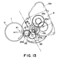
- Figure 13 is an illustration of a structure for stabilizing a pressure of a developing roller relative to a photosensitive drum.
- Figure 14 is an illustration of a structure for stabilizing a pressure of a developing roller relative to a photosensitive drum.
- Figure 15 is an exploded perspective view of a developing cartridge according to another embodiment of the present invention.
- Figure 16 is a perspective view of a guide portion providing the main assembly of the apparatus.
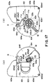
- Figure 17 (a), is a side view of the other end of the developing cartridge shown in Figure 15 (shutter is closed), and (b) is a side view of one end of a developing cartridge shown in Figure 15 (shutter is closed).
- Figure 18 (a), is a side view of the other end of the developing cartridge shown in Figure 15 (shutter is open), and (b) is a side view of one end of a developing cartridge shown in Figure 15 (shutter is open).
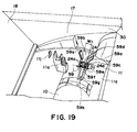
- Figure 19 is a perspective view of a guide portion in the main assembly of the apparatus.
- Figure 20 is a side view showing a process of mounting a developing cartridge to a rotary unit.
- Figure 21 is a side view showing a process of mounting a developing cartridge to a rotary unit.
- Figure 22 is a side view showing a process of mounting a developing cartridge to a rotary unit.
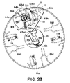
- Figure 23 is a side view showing a process of mounting a developing cartridge to a rotary unit.
- Figure 24 is a side view showing a process of mounting a developing cartridge to a rotary unit.
- Figure 25 is a side view showing a positional relation between a spring receptor and a boss.
- Figure 26 is a side view of a developing cartridge according to another embodiment.
- Figure 27 is a side view of a developing cartridge according to another embodiment.
- Figure 28 is a side view of a developing cartridge according to another embodiment.
- Figure 29 shows another embodiment.
- Figures 1 to Figure 3 illustrate an electrophotographic image forming apparatus
- Figures 4 to 5 are perspective view of a developing cartridge
- Figures 6 to Figure 10 are a mounting structure of the developing cartridge
- Figures 11 and 12 illustrate a drive transmission structure.
- FIG. 1 is a side view of a laser beam printer as an exemplary image forming apparatus for forming a color image through an electrophotographic process.
- Charging means 2 uniformly charges a surface of an electrophotographic photosensitive member in the form of a drum (photosensitive drum) 1 which rotates at a constant speed.
- a laser beam corresponding to image information is projected through exposure means 3 onto the photosensitive drum 1 to form latent images thereon, which are developed by developing device Dy, Dm, Dc or Db.
- the developed images formed on the photosensitive drum 1 are superimposedly transferred sequentially onto an intermediary transfer member 4 so that color image is formed.
- the color image is transferred by transferring means 6 onto a recording material P, such as recording paper, OHP sheet or the like fed by feeding means 5 from a sheet feeding portion.
- the recording material P is fed to fixing means 7, where the color image is fixed.
- the recording material P is then discharged to a discharging portion 8 at an upper surface of the device.
- the photosensitive drum 1 is integrally mounted to a frame of cleaning means 9 for removing developer (toner) remaining on the photosensitive drum 1 after transfer of the toner image onto the recording material P, thus constituting a process cartridge (drum unit) U.
- the process cartridge U is demountably mounted to the main assembly of the image forming apparatus, and is exchanged by a user by himself when the lifetime of the photosensitive drum 1 ends.
- the photosensitive drum 1 comprises an aluminum cylinder having a diameter of approx. 50 mm, and an organic photoconductive layer thereon, and is rotatably supported on a frame 9a of the cleaning means 9, which frame also functions as a holder for the photosensitive drum 1.
- a cleaning blade 9b for scraping and removing the toner remaining on the photosensitive drum 1, and charging means 2.
- the photosensitive drum 1, cleaning means 9 and the charging means 2 are unified into a process cartridge U detachably mountable to the main assembly of the apparatus.
- the photosensitive drum 1 receives driving force from an unshown driving motor to rotate in the counterclockwise direction in Figure 1 in accordance with image forming operation.
- the charging means 2 in this example is of contact charging type, and comprises a rotatable electroconductive roller in contact with the surface of the photosensitive drum 1, which roller is supplied with a voltage to uniformly electroconductive roller the surface of the photosensitive drum 1.
- an image signal is supplied to an unshown laser diode, in response to which the laser diode projects the image light corresponding to the image signal onto the polygonal mirror 3a.
- the polygonal mirror 3a is rotated at a high speed by a scanner motor 3b, and the image light reflected by the mirror 3a is projected onto the photosensitive drum 1 rotating at a constant speed through an imaging lens 3c and a reflection mirror 3d, so that surface of the photosensitive drum 1 is imagewisely exposed to the light, thus forming an electrostatic latent image.
- the latent image is developed for each color by the latent image developing cartridge (developing device).
- the structure of the developing cartridge will be described, hereinafter.
- the toner image developed by the developing cartridge is transferred onto the intermediary transfer member 4.
- the intermediary transfer member 4 Onto the intermediary transfer member 4, four color toner images on the drum are sequentially and superimposedly transferred. Therefore, the intermediary transfer member 4 is rotated clockwisely in Figure 1 in synchronism with the outer peripheral speed of the photosensitive drum 1.
- the intermediary transfer member 4 having the toner images is passed to sandwich the recording material P with a transfer roller 6 as transferring means supplied with a voltage, by which the toner images are simultaneously transferred from the intermediary transfer member 4 onto the recording material P.
- the intermediary transfer member 4 in this example comprises an aluminum cylinder having an outer diameter of approx. 150 mm, and an elastic layer of a material such as a intermediate resistance sponge, an intermediate resistance rubber or the like thereon. It is rotated by a gear fixed thereto.
- the cleaning means 9 has a cleaning blade 9b which is contacted to the drum surface and which scrapes the toner off the e drum surface.
- the scraped toner is accumulated in a toner container 9c.
- the capacity of the container 9c is such that it is not filled with the removed toner accumulated before the lifetime of the photosensitive drum 1 ends.
- the removed toner in the container 9c is taken out by exchange of the drum unit U when the life of the photosensitive drum 1 ends.
- the transferring means for transferring the toner images from the intermediary transfer member 4 onto the recording material P is in the form of a transfer roller 6 in this example, and the roller 6 comprises a metal shaft and an intermediate resistance foamed-elastic-member thereon, and is vertically movable in Figure 1.
- the transfer roller 6 takes a solid line position in Figure 1 (lower position) away from the intermediary transfer member 4 so that it does not disturb the image while the four toner images are being transferred thereonto, that is, while the intermediary transfer member 4 is rotated a plurality of times.
- the transfer roller 6 is moved to the upper position indicated by the chain line in Figure 1 by unshown cam at timing for transfer of the color image onto the recording material P.
- the roller press-contacts the recording member P to the intermediary transfer member 4 at a predetermined.
- the transfer roller 6 is supplied with a bias voltage so that toner image is transferred from the intermediary transfer member 4 onto the recording material P.
- the feeding means 5 for feeding the recording material P comprises a cassette 5a accommodating a plurality of recording materials P, a pick-up roller 5b, feeding rollers 5c1, retarding rollers 5c2 for preventing double feeding, a pair of feeding rollers 5d, a pair of registration rollers 5e, a pair of discharging rollers 5f, and a feeding guide 5g.
- the pick-up roller 5a is rotated in the image forming operation, so that recording material P in the cassette 5a is separated and fed in seriatim.
- the recording material is fed out of the cassette 5a, and is guided by the feeding guide 5f, and then is fed to the pair of registration rollers 5e via the pair of feeding rollers 5d.
- the registration roller 5e is at rest for stopping and retaining the recording material P, and is rotated to feed the recording material P to the intermediary transfer member 4 at a predetermined sequence to align the recording material P with the intermediary transfer member 4 for the transfer process. Then, the color image is transferred by the transferring means.
- the recording material P now having the transferred color image is fed to the fixing means 7 where the toner image is fixed.
- the fixing means 7 comprises a fixing roller 7a for applying heat to the recording material P, and a pressing roller 7b for press-contacting the recording material P to the fixing roller 7a. These rollers 7a, 7b are hollow rotatable rollers, and have heaters therein.
- the toner image is fixed on the recording material P while the recording material P is being fed therethrough while being pressed and heated.
- the recording material P on which the toner image is fixed is discharged to the discharging portion 8 by the discharging rollers 5f (feeding means).
- the image forming apparatus has four developing cartridges D (Dy, Dm, Dc, Db) for development in four colors (yellow, magenta, cyan and black) to form a full-color image.
- the developing cartridges D are demountably mounted on a rotary unit 11 which is rotatable about a shaft 10. In the image formation operation, each developing cartridge D is revolved while being supported on the rotary unit 11, about the shaft 10.
- a developing cartridge D accommodating predetermined color toner is stopped at a development position faced to the photosensitive drum 1.
- the developing roller which will be described hereinafter is positioned with small clearance relative to the photosensitive drum 1 (approx. 300 ⁇ m), and then the toner is supplied to the electrostatic latent image on the photosensitive drum 1 to development the latent image.
- the rotary unit 11 is rotated for each rotation of the intermediary transfer member 4 to permit developing operations of the yellow developing cartridge Dy accommodating the yellow color toner, the magenta developing cartridge Dm accommodating the magenta color toner, cyan developing cartridge Dc accommodating the cyan color toner, and the black developing cartridge Db accommodating the black color toner, in this order.
- FIG 3 show a developing cartridge D (yellow developing cartridge Dy, for example) placed at the development position faced to the photosensitive drum 1.
- the developing cartridge D comprises a developing roller 12 as a toner carrying member for supplying the toner to the photosensitive drum 1, and a toner accommodating portion 13a for accommodating the toner to be supplied to the developing roller 12. It further comprises a frame 13 for supporting the developing roller 12, and a shutter 14 for an opening provided in the frame 13 to exposure the developing roller 12. Furthermore, it comprises a toner feeding member 15 in the toner accommodating portion 13a.
- a fresh developing cartridge is provided with a toner seal 30 for preventing leakage of the toner accommodated in the toner accommodating portion 13a. A user pulls out the toner seal 30 prior to the mounting of the fresh developing cartridge to the main assembly of the apparatus to open the toner accommodating portion 13a. By this, the toner in the toner accommodating portion 13a is permitted to be supplied to the developing roller 12.
- the toner feeding member 15 is rotated by driving force from the main assembly of the apparatus to feed the toner from the accommodating portion 13a to the developing roller 12.
- the developing roller 12 is a rotatable aluminum roller, and a development blade 16 is press-contacted to the peripheral surface of the developing roller 12.
- each developing cartridge D is connected with the driving source and high voltage generating source for each color development provided in the main assembly of the image forming apparatus when the developing cartridge D is moved to development position, so that developing bias voltage for each developing cartridge D is sequentially applied thereto, and the driving force is transmitted to rotate the developing roller 12 or the like.
- the insertion opening 17 is normally closed by a cover 18.
- the main assembly of the apparatus 30 is provided with a developing device exchange switch (unshown).
- a developing device exchange switch (unshown).
- the user actuates the switch.
- the rotary unit 11 rotates to bring the developing cartridge to be replaced to the position of the insertion opening 17.
- guides 19 constituting the mounting means for the developing cartridge D are provided at four positions of the rotary unit 11 in the main assembly 30 of the image forming apparatus.
- the shutter 14 of the developing cartridge D is provided with guide portions 20 as shown in Figures 5 to 10.
- the user rotates the developing cartridge D, The shutter 14 is opened, and the developing roller 12 is faced to the photosensitive drum 1 exposed through the frame 13, so that developing operation is enabled.
- the rotary unit 11 as the mounting member carries the black developing cartridge Db for developing the latent image using the black color toner, the yellow developing cartridge Dy for development the latent image using yellow color toner, the magenta developing cartridge Dm for developing the latent image using the magenta color toner, and the cyan developing cartridge Dc for developing the latent. image using the cyan color toner.
- the frame 13 of the developing cartridge D is provided with an opening 13b extending in the longitudinal direction, and the developing roller 12 is mounted on the frame 13 so as to be exposed through the opening 13b.
- a projected portion 13c integral with the frame 13 is formed.
- the projected portion 13c functions as a guide when the developing cartridge D is inserted into the main assembly 30 of the image forming apparatus and as a center of rotation for the developing cartridge D.
- At least one of the projected portions 13c is cylindrical.
- a locking member 21 Adjacent to the projected portion 13c of the frame 13, there is provided a locking member 21 for locking the shutter 14 at the closed state.
- the locking member 21 has an engaging portion 21b in an arm portion 21a as a supporting portion having an elastic.
- a shutter engagement recess 14b as an engaging portion is provided at a predetermined position of the shutter side wall.
- the locking is automatically released to permit the opening of the shutter 14. This will be described in are detail.
- the guide 19 provided on the inner wall of the rotary unit 11 comprises two guiding member inserting portions 19a which are substantially parallel with each other, and a projection inserting portion 19b comprising a linear rib 19b1 and an arcuate rib 19b2.
- the user causes the guide portion 20 of the shutter 14 to be guided by the guide inserting portion 19a, and inserts the developing cartridge D.
- the projected portion 13c has cutting portions 13c1 which are provided by linearly cutting the cylindrical 1 portion in a direction parallel with the linear rib 19b1.
- projections 13d which are semi-spherical engaging portions are provided as shown in Figure 9, and correspondingly, the shutter 14 has holes 14c which are to be engaged with the projections 13d. Therefore, when the shutter 14 is closed, the projections 13d are engaged with the holes 14c. So, even if the locking by the locking member 21 of the shutter 14 is released, the developing cartridge frame 13 is prevented from rotating to an unstable position relative to the shutter 14.
- the cylindrical projected portion 13c of the frame 13 is rotatable in the arcuate rib 19b2 although the shutter 14 is not, because the guide portion 20 is sandwiched by the guide portion inserting portion 19a. Therefore, the semi-spherical projection 13d rotates to the predetermined position beyond the hole 14c of the shutter 14 (x direction in Figure 10). Since the shutter 14 is provided with the insertion guide portion 20, the frame 13 is easily rotated while the shutter 14 is in the fixed state. When it is rotated to a predetermined position, the frame 13 is positioning by a positioning means (unshown), so that developing cartridge D is mounted in place.
- the shutter 14 is open to expose and face the developing roller 12 to the photosensitive drum 1.
- the user can feel the rotation start position for the developing cartridge D on the basis of the click feeling provided by the removal of the semi-spherical projection 13d from the hole 14c the shutter 14.
- the diameter of the arcuate portion of the projected portion 13c is larger than the distance between the cutting portions 13c1, and therefore, the projected portion 13c is not disengaged from the linear rib 19b1 when the projected portion 13c is rotated at the position of the arcuate rib 19b2.
- the developing roller 12 is prevention from contamination by the dust or the like. Since the shutter 14 is provided with a locking mechanism, the shutter 14 is prevented from inadvertent opening.
- the shutter 14 maintains its closed state, and therefore, the developing roller 12 is not damaged during insertion.
- the user is not required to remove the developing roller protection member by his hands before insertion of the developing cartridge as in conventional system.
- the shutter locking is automatically released when the developing cartridge is mounted to the main assembly 30 of the image forming apparatus, and only by rotation thereof after the insertion, the shutter 14 is released, and the developing roller 12 is faced to the photosensitive drum 1, thus completing the mounting operation.
- the mounting operativity is improved.
- a driving force receptor 22 for receiving driving force from the main assembly of the apparatus 30 to rotate the developing roller 12 is provided in one of the cylindrical projected portions 13c at one of the frame ends.
- the gear 23a is meshed with a roller gear 23b mounted on the rotation shaft of the developing roller 12.
- the gear 23a is meshed also with the gear 23b mounted on the rotation shaft of the toner feeding member 15 through a gear 23c to transmit the rotating force to the toner feeding member 15.
- the end of the driving force receptor 22 is in the form of a rib, which constitutes a coupling connectable with a drive transmission member of the main assembly of the apparatus.
- the rotary unit 11 in the main assembly 30 of the image forming apparatus is provided with a drive transmission member 24 for transmitting the driving force from a motor N, on the shaft faced to the driving force receptor 22 when the developing cartridge D is mounted in place.
- the transmitting mechanism for transmitting the driving force to the drive transmission member 24 from the motor M is schematically shown by chain lines.
- the drive transmission member 24, as shown in Figure 11, is mounted for movement toward the shaft of the driving force receptor portion 22, and the end thereof is formed into a coupling engageable with the rib of the driving force receptor.
- the coupling has any shape by which when the drive transmission member 24 is moved to the receptor 22, they are engaged, and when one rotates the other rotates.
- the receptor 22 has a plurality of recesses 22a, and the drive transmission member 24 is provided with a plurality of projections 24a, correspondingly.
- the driving force receptor portion 22 is rotated.
- the drive transmission member 24 is moved toward the receptor 22 by a moving mechanism (unshown), and is engaged therewith to permit transmission of driving force to the developing roller 12 or the like.
- the developing cartridge D receives the rotating force at the driving force receptor from the drive transmission member 24 of the main assembly 30 of the image forming apparatus at the development position.
- a line X1 is defined as a line connecting a rotation center of the developing cartridge D about the projected portion 13c and the center of rotation of the photosensitive drum 1
- a line X2 is defined as a line connecting the rotation center of the projected portion 13c and the center of rotation of the developing roller 12.
- the developing roller 12 receives normally the force to bite into the photosensitive drum 1, so that developing roller 12 is stably urged toward the photosensitive drum 1 normally. This is advantageous in the so-called contact development, but it particularly advantageous in the non-contact development since the gap is stabilized.
- an urging means is provided to fix the developing cartridge while urging it toward the photosensitive drum 1 when the developing cartridge is at the development position
- M is a direction of the moment produced in the developing cartridge D by the urging direction P of the urging means
- Designated by X1 is a line connecting the center of rotation of the developing cartridge D provided by the projected portion 13c and the center of rotation of the photosensitive drum 1
- Designated by X2 is a line connecting the rotation center of the projected portion 13c and the center of rotation of the developing roller 12
- the hen the line X2 is located upstream of the line X1 with respect to the moment direction M as seen from the rotation center of the projected portion 13c.
- the urging means urges the rear surface portion adjacent the toner accommodating portion 130 at each of the longitudinal ends of the developing cartridge D.
- the developing cartridge D is demountably mountable relative to the full-color laser beam printer shown in Figure 1.
- the developing cartridge D comprises a developing roller 12, development blade 16 and toner accommodating portion 63a in the cartridge frame 63.
- guides 59 constituting mounting means for the developing cartridge D are provided at four positions 4 of the rotary unit 11 in the main assembly 30 of the image forming apparatus.
- the shutter 64 of the developing cartridge D is provided with a guide portion 70, as shown in Figures 15, 17 and Figure 18.
- the guide portion 70 is provided only on one side (in the longitudinal direction or the rotation axial direction of the developing roller 12) of the developing cartridge D. Therefore, the guide 59 is also provided only on one of the wall surfaces 11a of the rotary unit 11.
- the developing cartridge D is inserted to the rotary unit 11 in a direction crossing with the longitudinal direction of the developing roller 12 with the developing roller 12 being at a leading side, while the user grips the grip 63e.
- the user rotates the developing cartridge D, by which the shutter 64 is opened to permit the developing roller 12 to be exposed and faced through the frame 63 to the photosensitive drum 1, thus enabling the developing operation.
- the developing cartridge D mounted to the mounting position of the rotary unit 11 is urged in the longitudinal direction by a spherical urging member 26b positioned at the arcuate engaging portion 26a of the guide 26 provided on the other wall surface 11b of the rotary unit 11 (namely, urged to the side having the driving force receptor 22).
- the urging member 26b is urged elastically by a spring (unshown).
- the developing cartridge D is urged toward the driving side. Therefore, the developing cartridge D is mounted to the rotary unit 11 (main assembly of the apparatus), using as a reference the side having the driving force receptor member 22 in the longitudinal direction of the developing roller 12.
- Figure 16 is a perspective view of the developing cartridge D wherein shutter 64 or the like is omitted.
- Figure 17, (a), (b), is both side views of the developing cartridge D when the shutter 64 is closed
- Figure 18, (a), (b) is both side views of the developing cartridge when the shutter 64 is opened.
- the frame 63 of the developing cartridge D is provided with an opening 63b extended in the longitudinal direction, and the developing roller 12 is mounted on the frame 63 so as to be exposed through the opening 63b.
- a projected portion 63c integral with the frame 13 is formed.
- the projected portion 63c functions as a guide when the developing cartridge D is inserted into the main assembly 30 of the image forming apparatus and as a center of rotation for the developing cartridge D.
- the projected portions 63c is cylindrical.
- a projected portion 63g is demountably mounted on the frame 63 (frame 63 shows the demounted state).
- the projected portion 63g is mounted to the frame 63 by inserting the inserting portion 63g1 into a hole (unshown) formed in the side 63i.
- the end of the inserting portion 63g1 is provided with a claw configuration portion (unshown), and by engaging the claw portion with the frame 63, projected portion 63g is mounted on the frame 63.
- the developing cartridge D urged toward the side 63h (in the direction indicated by the arrow Q).
- the developing cartridge D is mounted to the rotary unit 11 of the main assembly of the apparatus 30, using, as a reference, the side 63h of the driving force receptor member 22.
- Both of the longitudinal ends of the developing roller 12 are provided with spacer rollers 12a, 12b, respectively. Therefore, at the development position, the spacer rollers 12a, 12b are urged to the peripheral surface of the photosensitive drum 1 by the urging force of the urging means 25, similarly to the foregoing, so that predetermined gap is maintained between the developing roller 12 and the photosensitive drum 1.
- the developing blade 16 is of rubber, and is mounted to the frame 63 by mounting a plate 16a to the frame with screws 16b.
- a locking member 71 is mounted to one side of the developing cartridge D (in Figure 16, it is omitted).
- the locking member 71 is mounted on a cartridge frame portion 63h at one longitudinal end portion of the developing roller 12 as the developing means. It comprises a locking engaging portion 71b engageable with the shutter engaging portion 64b provided in the shutter portion 64, a supporting portion 71a for supporting the locking engaging portion 71b, a mounting portion 71c mounted to the cartridge frame portion 63h. Designated by 63j is a hole into which the mounting portion is inserted.
- the locking member 71 is an integrally-molded product of plastic resin material, and locks the shutter at the closing position by engagement between the locking engaging portion 71h and the shutter engaging portion 64b.
- a projection 63d as a semi-spherical engaging portion is provided only on one longitudinal end of the developing cartridge frame 63, as shown in Figure 18.
- the shutter 64 is provided with an engaging portion in the form of a hole 64c engageable with the projection 63d. Therefore, when the shutter 64 is in the closing position, the projection 63d is engaged in hole 64c. So, even if the locking by the locking member 21 of the shutter 14 is released, the developing cartridge frame 13 is prevented from rotating to a n unstable position relative to the shutter 14.
- One and the other ends of the cartridge frame 63 are provided with an orientation determination boss 63m and a spring receptor portion 63k in the form of projections.
- (a), designated by 73 is a grip for pulling a toner seal out, and it is used when it is to be removed.
- the shutter 64 will be described.
- Both side walls 64e, 64f of the shutter 64 are provided with round holes 640a, which are engaged with the projected portion 63c, s 63g, by which the shutter 64 is rotatably mounted to the frame 63.
- the opening 63b is closed, and the developing roller 12 is covered by the shutter 64.
- the shutter 64 is closed, so that developing roller 12 is protected from deposition of foreign matters such as dust, and the roller 12 or the like is protected from damage. In addition, foreign matter does not enter the developing cartridge D.
- the shutter 64 is in the closing position by the locking portion 71, the shutter 64 is locked at the closing position by the locking of the engaging portion 71band the engagement recess 64b, so that it is prevented from unintentional opening.
- the locking is automatically released to permit the opening of the shutter 64.
- a guide 59 as a supporting member provided in one of the inner walls 11a of the rotary unit 11, comprises a guide inserting portion 59b having an inclined portion 59a inclined and open upwardly, a projected portion inserting portion 59d having substantially parallel linear ribs 59c, an engaging portion 59f as a supporting member having an arcuate rib 59e, and guide portion inserting portion 59h having substantially parallel DC ribs 59g continuing to the he engaging portion 59f.
- the user inserts the developing cartridge D while guiding the guide portion 70 and projected portion 63c of the shutter 64 along the guide inserting portion 59a ( Figure 20).
- the projected portion 63c at one end of the developing cartridge D enters the linear portion of the projected portion inserting portion 59d.
- the projected portion 63c is provided with a cutting portion 63c1 which is provided by linearly cutting a cylinder at an angle parallel the linear rib 59c.
- the two linear ribs 59c which are engageable therewith has a width which permits only the parallel translational motion of the cutting portion 63c1 (direction W1 in Figure 19). Therefore, when the developing cartridge D is inserted while the cutting portion 63c1 is engaged with the linear rib 59c, the developing cartridge D maintains a predetermined angle (orientation).
- the projected portion 63g at the other side 63i of the developing cartridge D is guided by the inclined portion 26c of the guide 26 and enters the guide inserting portion 26d.
- the cutting portion 63g3 is engaged with the linear rib 26e, and the developing cartridge D is inserted, maintaining the predetermined angle (orientation), similarly to the case of the projected portion 63c. It is inserted until the projected portion 63g reaches the arcuate rib (engaging portion) 26a.
- the arcuate rib 26a has a radius for permitting rotation of the projected portion 63g.
- the projected portion 63c of one longitudinal end of the frame 63 is supported by the arcuate rib 59c of the guide 59, and the projected portion 63g at the other end is supported by the arcuate rib 26a of the guide 26, and the developing cartridge D is supported on the rotary unit 11 for rotation about the both projected portions 63c and 63g.
- the user pushes by hand the grip portion 63e of the frame 63 in the state shown in Figure 22.
- the shutter 64 is fixed since the guide portion 70 is sandwiched by the guide portion inserting portion 59h, but the frame 63 is rotatable since the cylindrical projected portion 63c is rotatable in the arcuate rib 59e. Since the projected portion 63g is rotatable at the arcuate rib 26a, the semi-spherical projection 63d rotates beyond the hole 64c of the shutter 64 to a predetermined position (in the direction of an arrow X in Figure 22).
- the shutter 64 is provided with an insertion guide portion 70, and therefore, the frame 63 is easily rotated while the shutter 64 is stationary.
- the frame 63 is positioned by positioning means which will be described hereinafter, and the developing cartridge D is mounted in place.
- the orientation determination bosses 63m provided on the ends 63h, i of the developing device frame 63 lowers translatable slide members 10a provided on the opposite ends of the center shaft 10 of the rotary unit and urged by springs 10b.
- the slide portion 10a is slidable by engagement between the elongated hole 10a1 and the shaft 10c.
- the spring receptor portion 63k provided on the opposite lateral ends of the frame 63 are pressed by the spring 11a provided at the end portions of the rotary unit.
- the developing cartridge D is mounted at a predetermined position of the rotary unit 11.
- Designated by 11j is a guide portion for guiding the boss 63m.
- the shutter 64 is opened relative to the frame 63 to permit the developing roller 12 is exposed and faced to the photosensitive drum 1.
- the user can feel the rotation start position for the developing cartridge D on the basis of the click feeling provided by the removal of the semi-spherical projection 63d from the hole 64c the shutter 64.
- the diameter of the arcuate portion of the projected portion 63c is larger than the distance between the cutting portions 63c1, and therefore, the projected portion 63c is not disengaged from the linear rib 59c when the projected portion 63c is rotated at the position of the arcuate rib 59c.
- the user rotates the frame 63 in the opposite direction, by which the cutting portion 63c1 is brought into parallel with the linear rib 59c, and the shutter 64 is closed.
- the user can feel the rotation completion position of the developing cartridge D on the basis of the click feeling upon the engagement of the semi-spherical projection 63d into the hole 64c.
- the arm portion 71a of the locking member 71 elastically restores, and the engaging portion 71b enters the engagement recess 64b, as shown in Figure 21. By this, the shutter 64 is automatically locked.
- the developing cartridge D is provided with a shutter 64, the developing roller 12 is protected from deposition of foreign matter such as dust, and since the shutter 64 is provided with the locking mechanism, the shutter 64 is prevented from unintentionally opened.
- the shutter 64 maintains its closed state, and therefore, the developing roller 12 is not damaged during insertion. Additionally, it is not necessary for the user to remove a developing roller protection member or the like before insertion of the developing device.
- the shutter locking is automatically released when the developing cartridge is mounted to the main assembly 30 of the image forming apparatus, and only by rotation thereof after the insertion, the shutter 64 is released, and the developing roller 12 is faced to the photosensitive drum 1, thus completing the mounting operation.
- the mounting operativity is improved.
- One longitudinal end portion 63h of the developing roller 12 will be described, and the same applies to the other end portion 63i.
- the spring receptor portion 63k is disposed within a range of approx. 100 - 130 degrees from a line 11 connecting a center of rotation M1 of the developing roller 12 and the center of rotation M2 of the driving force receptor portion 22 as seen in the longitudinal direction of the developing roller 12.
- the spring receptor portion 63k1 (63k2) is disposed at such a position that angle formed between the line 11 connecting the center of rotation M1 of the developing roller 12 and the center of rotation M2 of the driving force receptor member 22, and the line 12 connecting the spring receptor surface 63k3 and the center of rotation M1, is approx. 100 - 130 degrees. In this example, the angle is approx. 115 degrees.
- the boss 63m (63m1, 63m2) is disposed within a range of approx. 130 - 150 degrees from the line 11 across the line 11 from the spring receptor portion 63k.
- the angle formed between the line 11 and a line 13 connecting the center of the boss 63m and the center of rotation M1 is approx. 130 - 150 degrees. In this example, the angle is approx. 140 degrees.
- the spring receptor portion 63k By disposing the spring receptor portion 63k (63k1, 63k2) and the boss 63m (63m1, 63m2), the spring receptor portion 63k can properly receive the elastic force of the spring 11a provided in the main assembly of the apparatus 30. In addition, the boss 63m properly abuts the shaft 10. Therefore, the developing cartridge D is accurately positioned to the mounting position.
- the boss 63m (63m1, 63m2) is projected outwardly from the side surface 63h, i of the frame 62 by approx. 2 mm - 15 mm. In this example, the boss 63m is projected by approx. 4 mm.
- the spring receptor portion 63k (63k1, 63k2) is projected outwardly from the side surface 63h, i by approx. 2 mm - 20 mm.
- the spring receptor portion 63k1 is projected by approx. 10 mm
- 63k2 is projected by approx. 6 mm. Therefore, a projection length is larger in the spring receptor portion 63k1 provided at a driving force receiving side.
- the developing cartridge for developing a latent image formed on the photosensitive member wherein said developing cartridge is detachably mountable to a main assembly of an electrophotographic image forming apparatus, and wherein the main assembly includes a main assembly guide for guiding said developing cartridge toward a mounting position in the main assembly, and includes a fixed portion, said developing cartridge comprises: a cartridge frame of plastic resin material; a developing roller 12 for developing, with toner, the latent image formed on the photosensitive member 1 of the main assembly of the apparatus, when mounted to the main assembly of the electrophotographic image forming apparatus, wherein said developing roller carries on its peripheral surface an amount of toner regulated by a development blade 16; a driving force receptor member 22 for receiving, from the main assembly of said device, driving force for rotating said developing roller when said cartridge is mounted to the main assembly, said driving force receptor means being provided exposed adjacent one end of said cartridge frame portion 63h in a longitudinal direction of said developing roller; a toner accommodating portion 63a for accommodating the toner; a shutter 64 of plastic resin material which is
- Said supporting portion 64e is rotatable about the same axis as that of said driving force receptor member 22.
- Said cartridge guide 70 has an elongated shape, and is extended toward said driving force receptor means 22.
- Said cartridge D further comprises an urged portion 63g on said cartridge frame portion adjacent said one end, wherein said urged portion is urged by elastic force of a spring member provided in the main assembly of the apparatus, wherein said developing cartridge is urged toward said one end by the elastic force of said spring member.
- Said guide 70 is movable along an outside of said frame portion 63g adjacent said one end.
- Said guide 70 has an elongated shape, and is rotatable about said driving force receptor member 22. A longitudinal direction of said guide 70 is directed to said driving force receptor member 22.
- the cartridge further comprises a rotatable member (shutter 64) rotatably mounted on said frame portion 63.
- Said guide is provided on said rotatable member.
- Said guide 70 is provided on said rotatable member 64.
- Said rotatable member 64 includes a shutter 64 for covering a portion of said developing means exposed from said cartridge frame 63.
- Said shutter 64 is movable between a closing position for covering said exposed portion and an opening position for exposing said developing means.
- Said guide 70 is projected longitudinally outwardly and is provided on said shutter 64.
- Said guide 74 is provided on a portion of said shutter 64 which is movable along an outside of said cartridge frame portion 63h adjacent said one end.
- Said first projected portion 63c includes two flat surface portions 63c1, opposed to each other, for guiding said developing cartridge toward the mounting position in the main assembly when said cartridge is mounted to said main assembly, and two curved surface portions 63c2, opposed to each other, for engaging with a recess 59f of said first supporting member 59.
- Said second projected portion 63g includes two flat surface portions 63g3, opposed to each other, for guiding said developing cartridge toward the mounting position in the main assembly when said cartridge is mounted to said main assembly, and two curved surface portions 63g4, opposed to each other, for engaging with a recess 26a of said second supporting member 26.
- a distance L1 between outer surfaces of said flat surface portions 63c1 of said first projected portion is approx. 13 mm - 15 mm
- a distance L2 between outer surfaces of said flat surface portions 63g3 of said second projected portion 63g is approx. 2 mm - 9 mm.
- L1 is approx. 15 mm
- L2 is approx. 9 mm.
- a distance L3 ( Figure 17, (b)) between remotest outer surface portions of said curved surface portions 63c2 of said first projected portion 63c is approx. 13 mm - 17 mm
- a distance L4 ( Figure 17, (a)) between remotest outer surface portions of said curved surface portions 63g4 of said second projected portion 63g is approx. 7 mm - 11 mm.
- L3 is approx. 17 mm
- L4 is approx. 11 mm.
- Said driving force receptor member 22 is enclosed by said first projected portion 63c.
- Said driving force receptor member 22 is provided with a recess 22a for engagement with a projection 24a of the main assembly of the apparatus, wherein by engagement between said projection and said recess, driving force is transmitted from the main assembly to said developing means.
- Said curved surface portion is of continuous arcuate configuration.
- said developing cartridge D rotates from said mounting position ( Figure 24) to a development position ( Figures 13 and 14) for developing a latent image formed on the photosensitive member, said developing cartridge rotates about said first projected portion 63c and second projected portion 63g.
- Said developing cartridge reaches said mounting position ( Figure 24) by approx. 90 - 120 degrees rotation from a mounting-and-demounting position ( Figure 22) about said first projected portion 63c and said second projected portion 63g.
- Said mounting-and-demounting position ( Figure 22) is a position where said first projected portion 63c and said second projected portion 63g enters said first supporting member 59 and said second supporting member 26, and where said flat surface portion 63g3 is opposing to engaging portions of said first supporting member and said second supporting member, respectively. In this embodiment, it is rotated through approx. 105 degrees.
- Said developing cartridge reaches a developing position by approx. 5 - 10 degrees rotation from said mounting position about the first projected portion 63c and the second projected portion 63g.
- Said developing position is a position where spacer rollers 12a of said developing member is urged to said electrophotographic photosensitive member 1. In this embodiment, it is rotated through approx. 7 degrees.
- the guide 70 functions to guide the developing cartridge D into the main assembly, and is displaceable relative to the first projection.
- the guide 70 has an elongated shape, and rotates through approx. 90 - 120 degrees the first projected portion 63c to mounted the developing cartridge at the mounting position in main assembly of the apparatus.
- the cartridge further comprises a driving force receptor member 22 for receiving, from the main assembly of said device, driving force for rotating said developing roller 12 when said developing cartridge is mounted to the main assembly of said device, wherein said driving force receptor member 22 is provided on the same longitudinal end as having said first projected portion 63c, and wherein said guide is provided only of the same side.
- the guide 70 is provided only on one side 63h, and therefore, the developing cartridge D can be smoothly mounted.
- the mounting position of the developing cartridge is a position where the developing cartridge is correctly positioned in place in the main assembly of the apparatus.
- the development position of the developing cartridge is a position where the developing cartridge is positioned for effecting the development operation.
- the mounting-and-demounting position of the developing cartridge is a position where the developing cartridge is mounted to or demounted from the supporting member provided in the main assembly of the apparatus.
- the supporting member is a member for supporting the developing cartridge when the developing cartridge is to be mounted to the mounting position.
- the first receptor portion 63k and the second one 63k are flat in shape, and receive the urging forces from the first urging member 11a and the second one 11a.
- Said first contact portion 63m1 and second contact portion 63m2 are in the form of circular columns, and its peripheral surface portions are contacted to said first fixed portion 10 and second fixed portion 10.
- the structures of the cartridge frame, the developing roller, the driving force receptor member, the toner accommodating portion, the shutter, cartridge guide, the locking member, the fixing portion, the first projected portion, the second projected portion, the first and second urging force receptors, the portion, the second urging force receptor, the portion, the first contact portion, the second contact portion, the first fixing portion, and second fixing portion, are not limited to those described above, but may be modified.
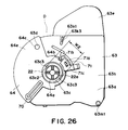
- Figure 26 is a side view of one end of the developing cartridge D.
- the linear portion 63c1 may be provided with at least one projection 63c3 so that width is smaller than the rib clearance W1 ( Figure 19) of the inlet of the guide 59. The insertion is possible with the structure.
- cylindrical projection 63c provided on a side 63h of the frame 63 of the developing cartridge, has a configuration having a plurality of projections 63c4 contactable to the arcuation of such a diameter D2 as is engageable with the diameter D1 ( Figure 19) of the arcuate rib of the guide 59.
- the contact resistance with the rib of the guide 59 can be decreased to make smooth the rotation upon mounting of the developing cartridge D to the main assembly of the apparatus 30.
- Figure 28 shows a further example wherein the structures of Figures 26 and 27 are used in combination, as will be understood from this Figure.
- the shutter 80 is removed from the cartridge frame 63 by a user, or is mounted by the user.
- the guide 70 is provided in a rotatable member not in the shutter 80.
- the rotatable member 81 is rotatable about a projection 63c along a side 63h of the cartridge frame. It is locked by the above-described locking member 71. Therefore, the guide 70 has the same function as described in the foregoing, and the developing cartridge D can be mounted to the main assembly 30 in the same manner.
- the shutter 80 Prior to mounting the developing cartridge D to the main assembly 30, the shutter 80 is removed from the frame 63 by the user. When the cartridge D is demounted from the main assembly 30, the shutter is remounted to the frame by the user, as desired.
- the shutter is not inevitable, and may not be provided.
- the guide 70 may not be provided on the rotatable member 81, but may be mounted directly on the cartridge frame. In this case, the guide is rotatably mounted on the cartridge frame 63.
- the projections on longitudinal end surfaces of the developing cartridge frame are guided when the developing cartridge is mounted to the main assembly of the image forming apparatus, so that developing cartridge can be inserted in a direction perpendicular to the longitudinal direction, and therefore, the insertion stroke can be reduced to improve the insertion operativity.
- the driving connection between the developing cartridge and the main assembly is effected with the coupling configuration, so that decrease of the driving accuracy due to the driving gear pitch non-uniformity, for example, can be prevented.
- the foregoing cartridge frame, shutter or the like are of plastic resin material such as polystyrene, ABS resin, polycarbonate, polyethylene, polypropylene, or the like.
- the process cartridge is not limited to those described in the foregoing, but may contain as an unit at least one process means such as charging means, cleaning means or the like, and an electrophotographic photosensitive member, wherein cartridge is detachably mountable relative to the main assembly of an electrophotographic image forming apparatus.
- the mounting operativity of the developing cartridge is improved.
- the developing cartridge can be smoothly mounted in the main assembly of the electrophotographic image forming apparatus.
Abstract

Description
- The present invention relates to a developing cartridge for developing a latent image formed on an electrophotographic photosensitive member when an image is formed on a recording material through an electrophotographic process, and an electrophotographic image forming apparatus using the developing cartridge.
- Heretofore, the following structure is known as multi-color image forming apparatus for forming a multi-color image on a recording material through an electrophotographic process. A plurality of developing devices accommodating different color developers which are arranged on a rotation selection mechanism, are disposed around an electrophotographic photosensitive drum. A developing device accommodating a color developer is brought to be faced to the photosensitive drum to develop a latent image thereon. The developed image is transferred onto the recording material. The developing and transferring operations are carried out for respective colors, so that multi-color image is formed. The developing device is in the form of a cartridge which is detachably mountable to the main assembly of the image forming apparatus to facilitate the maintenance operation of the users.
- Generally, the structure for inserting the developing device into the main assembly of the apparatus is such that developing device is inserted in the longitudinal direction of the developing roller from a predetermined position, in order to reduce the area of the opening of the main assembly.
- The present invention is intended to further improve such a developing device.
- Accordingly, a principal object of the present invention is to provide a developing cartridge having an improved operability and an image forming apparatus to which the developing cartridge is detachably mountable.
- It is another object of the present invention to provide a developing cartridge having an improved mounting-demounting operability and an image forming apparatus to which the developing cartridge is detachably mountable.
- It is a further object of the present invention to provide a developing cartridge which a user can easily mounts it to and demounting it from a main assembly of an image forming apparatus and an image forming apparatus to which the developing cartridge is detachably mountable.
- It is a further object of the present invention to provide a developing cartridge having a projection engageable with a recess in a main assembly of an image forming apparatus, and a guide for guiding the cartridge toward the mounting position, the guide being movable relative to the cartridge frame, and an image forming apparatus to which the developing cartridge is detachably mountable.
- According to an aspect of the present invention, there is provided a developing cartridge for developing a latent image formed on the photosensitive member, wherein the developing cartridge is detachably mountable to a main assembly of an electrophotographic image forming apparatus, the developing cartridge comprising: a cartridge frame; developing means for developing, with toner, the latent image formed on the photosensitive member of the main assembly of the apparatus, when mounted to the main assembly of the electrophotographic image forming apparatus; a first projected portion projected from a frame portion of the cartridge adjacent one longitudinal end of the developing means, wherein the first projected portion is supported by a first supporting member provided in the main assembly, when the cartridge is mounted to the main assembly of the electrophotographic image forming apparatus; a second projected portion projected from the frame portion adjacent the other longitudinal end of the developing means, wherein the second projected portion is supported by a second supporting member provided in the main assembly, when the cartridge is mounted to the main assembly of the electrophotographic image forming apparatus; a driving force receptor member for receiving, from the main assembly of the device, driving force for rotating the developing means, when the cartridge is mounted to the main assembly, wherein the driving force receptor member is exposed from the frame portion adjacent the one end; and a guide, provided in the cartridge frame for guiding the developing cartridge toward a mounting position when the cartridge is mounted to the main assembly.
- These and other objects, features and advantages of the present invention will become more apparent upon a consideration of the following description of the preferred embodiments of the present invention taken in conjunction with the accompanying drawings.
- Figure 1 is an illustration of an electrophotographic image forming apparatus according to a embodiment of the present invention.
- Figure 2 is illustrations of a rotary unit and a developing cartridge.
- Figure 3 is an illustration of a developing cartridge.
- Figure 4 is an illustration of a mounting means for a developing cartridge, provided in the main assembly of an image forming apparatus.
- Figure 5 is a perspective view of a developing cartridge when the shutter is closed.
- Figure 6 is a perspective view of a developing cartridge when the shutter is opened.
- Figure 7 is an illustration of a developing cartridge when it is inserted into a main assembly.
- Figure 8 is an illustration of a developing cartridge when it is inserted into a main assembly.
- Figure 9 is an illustration of a developing cartridge when it is inserted into a main assembly.
- Figure 10 is an illustration of a developing cartridge when it is inserted into a main assembly.
- Figure 11 is an illustration of a drive transmission structure which stabilizes a positional relation between a developing roller and a photosensitive drum.
- Figure 12 is an illustration of a drive transmission structure which stabilizes a positional relation between a developing roller and a photosensitive drum.
- Figure 13 is an illustration of a structure for stabilizing a pressure of a developing roller relative to a photosensitive drum.
- Figure 14 is an illustration of a structure for stabilizing a pressure of a developing roller relative to a photosensitive drum.
- Figure 15 is an exploded perspective view of a developing cartridge according to another embodiment of the present invention.
- Figure 16 is a perspective view of a guide portion providing the main assembly of the apparatus.
- Figure 17, (a), is a side view of the other end of the developing cartridge shown in Figure 15 (shutter is closed), and (b) is a side view of one end of a developing cartridge shown in Figure 15 (shutter is closed).
- Figure 18, (a), is a side view of the other end of the developing cartridge shown in Figure 15 (shutter is open), and (b) is a side view of one end of a developing cartridge shown in Figure 15 (shutter is open).
- Figure 19 is a perspective view of a guide portion in the main assembly of the apparatus.
- Figure 20 is a side view showing a process of mounting a developing cartridge to a rotary unit.
- Figure 21 is a side view showing a process of mounting a developing cartridge to a rotary unit.
- Figure 22 is a side view showing a process of mounting a developing cartridge to a rotary unit.
- Figure 23 is a side view showing a process of mounting a developing cartridge to a rotary unit.
- Figure 24 is a side view showing a process of mounting a developing cartridge to a rotary unit.
- Figure 25 is a side view showing a positional relation between a spring receptor and a boss.
- Figure 26 is a side view of a developing cartridge according to another embodiment.
- Figure 27 is a side view of a developing cartridge according to another embodiment.
- Figure 28 is a side view of a developing cartridge according to another embodiment.
- Figure 29 shows another embodiment.
- A developing cartridge and an electrophotographic image forming apparatus according to embodiments of the present invention will be described.
- Referring to Figures 1 to 12, the first embodiment of the present invention will be described. Figures 1 to Figure 3 illustrate an electrophotographic image forming apparatus; Figures 4 to 5 are perspective view of a developing cartridge; Figures 6 to Figure 10 are a mounting structure of the developing cartridge; and Figures 11 and 12, illustrate a drive transmission structure.
- First, the description will be made as to a general arrangement of the electrophotographic image forming apparatus, and then as to the structure of the developing cartridge.
- The general arrangement of the electrophotographic image forming apparatus of this embodiment will be described. Figure 1 is a side view of a laser beam printer as an exemplary image forming apparatus for forming a color image through an electrophotographic process. Charging means 2 uniformly charges a surface of an electrophotographic photosensitive member in the form of a drum (photosensitive drum) 1 which rotates at a constant speed. A laser beam corresponding to image information is projected through exposure means 3 onto the
photosensitive drum 1 to form latent images thereon, which are developed by developing device Dy, Dm, Dc or Db. The developed images formed on thephotosensitive drum 1 are superimposedly transferred sequentially onto anintermediary transfer member 4 so that color image is formed. The color image is transferred by transferring means 6 onto a recording material P, such as recording paper, OHP sheet or the like fed by feeding means 5 from a sheet feeding portion. The recording material P is fed to fixing means 7, where the color image is fixed. The recording material P is then discharged to adischarging portion 8 at an upper surface of the device. - The structures of the respective portions will be described.
- The
photosensitive drum 1 is integrally mounted to a frame of cleaning means 9 for removing developer (toner) remaining on thephotosensitive drum 1 after transfer of the toner image onto the recording material P, thus constituting a process cartridge (drum unit) U. The process cartridge U is demountably mounted to the main assembly of the image forming apparatus, and is exchanged by a user by himself when the lifetime of thephotosensitive drum 1 ends. - The
photosensitive drum 1 comprises an aluminum cylinder having a diameter of approx. 50 mm, and an organic photoconductive layer thereon, and is rotatably supported on aframe 9a of the cleaning means 9, which frame also functions as a holder for thephotosensitive drum 1. Around thephotosensitive drum 1, there are provided acleaning blade 9b for scraping and removing the toner remaining on thephotosensitive drum 1, and charging means 2. In this example, thephotosensitive drum 1, cleaning means 9 and the charging means 2 are unified into a process cartridge U detachably mountable to the main assembly of the apparatus. - The
photosensitive drum 1 receives driving force from an unshown driving motor to rotate in the counterclockwise direction in Figure 1 in accordance with image forming operation. - The charging means 2 in this example is of contact charging type, and comprises a rotatable electroconductive roller in contact with the surface of the
photosensitive drum 1, which roller is supplied with a voltage to uniformly electroconductive roller the surface of thephotosensitive drum 1. - In the exposure means 3 for exposing the charged
photosensitive drum 1, an image signal is supplied to an unshown laser diode, in response to which the laser diode projects the image light corresponding to the image signal onto thepolygonal mirror 3a. Thepolygonal mirror 3a is rotated at a high speed by ascanner motor 3b, and the image light reflected by themirror 3a is projected onto thephotosensitive drum 1 rotating at a constant speed through animaging lens 3c and areflection mirror 3d, so that surface of thephotosensitive drum 1 is imagewisely exposed to the light, thus forming an electrostatic latent image. - The latent image is developed for each color by the latent image developing cartridge (developing device). The structure of the developing cartridge will be described, hereinafter.
- The toner image developed by the developing cartridge is transferred onto the
intermediary transfer member 4. Onto theintermediary transfer member 4, four color toner images on the drum are sequentially and superimposedly transferred. Therefore, theintermediary transfer member 4 is rotated clockwisely in Figure 1 in synchronism with the outer peripheral speed of thephotosensitive drum 1. Theintermediary transfer member 4 having the toner images is passed to sandwich the recording material P with a transfer roller 6 as transferring means supplied with a voltage, by which the toner images are simultaneously transferred from theintermediary transfer member 4 onto the recording material P. - The
intermediary transfer member 4 in this example comprises an aluminum cylinder having an outer diameter of approx. 150 mm, and an elastic layer of a material such as a intermediate resistance sponge, an intermediate resistance rubber or the like thereon. It is rotated by a gear fixed thereto. - After the toner image is transferred onto the
intermediary transfer member 4, a small amount of toner remains on the surface of thephotosensitive drum 1, and is removed by cleaningmeans 9. The cleaning means 9 has acleaning blade 9b which is contacted to the drum surface and which scrapes the toner off the e drum surface. The scraped toner is accumulated in atoner container 9c. The capacity of thecontainer 9c is such that it is not filled with the removed toner accumulated before the lifetime of thephotosensitive drum 1 ends. The removed toner in thecontainer 9c is taken out by exchange of the drum unit U when the life of thephotosensitive drum 1 ends. - The transferring means for transferring the toner images from the
intermediary transfer member 4 onto the recording material P, is in the form of a transfer roller 6 in this example, and the roller 6 comprises a metal shaft and an intermediate resistance foamed-elastic-member thereon, and is vertically movable in Figure 1. - The transfer roller 6 takes a solid line position in Figure 1 (lower position) away from the
intermediary transfer member 4 so that it does not disturb the image while the four toner images are being transferred thereonto, that is, while theintermediary transfer member 4 is rotated a plurality of times. - After the toner images are superimposedly transferred onto the
intermediary transfer member 4, and the color image formation is completed on theintermediary transfer member 4, the transfer roller 6 is moved to the upper position indicated by the chain line in Figure 1 by unshown cam at timing for transfer of the color image onto the recording material P. Thus, the roller press-contacts the recording member P to theintermediary transfer member 4 at a predetermined. Simultaneously with this, the transfer roller 6 is supplied with a bias voltage so that toner image is transferred from theintermediary transfer member 4 onto the recording material P. - The feeding means 5 for feeding the recording material P, comprises a cassette 5a accommodating a plurality of recording materials P, a pick-up
roller 5b, feeding rollers 5c1, retarding rollers 5c2 for preventing double feeding, a pair of feeding rollers 5d, a pair ofregistration rollers 5e, a pair of dischargingrollers 5f, and afeeding guide 5g. - At the time of the image formation, the pick-up roller 5a is rotated in the image forming operation, so that recording material P in the cassette 5a is separated and fed in seriatim. The recording material is fed out of the cassette 5a, and is guided by the feeding
guide 5f, and then is fed to the pair ofregistration rollers 5e via the pair of feeding rollers 5d. In the image forming operation, theregistration roller 5e is at rest for stopping and retaining the recording material P, and is rotated to feed the recording material P to theintermediary transfer member 4 at a predetermined sequence to align the recording material P with theintermediary transfer member 4 for the transfer process. Then, the color image is transferred by the transferring means. - The recording material P now having the transferred color image is fed to the fixing means 7 where the toner image is fixed. The fixing means 7 comprises a fixing
roller 7a for applying heat to the recording material P, and apressing roller 7b for press-contacting the recording material P to the fixingroller 7a. Theserollers - The recording material P on which the toner image is fixed, is discharged to the discharging
portion 8 by the dischargingrollers 5f (feeding means). - The description will be made as to the developing cartridge for developing the latent image formed on the
photosensitive drum 1. - The image forming apparatus has four developing cartridges D (Dy, Dm, Dc, Db) for development in four colors (yellow, magenta, cyan and black) to form a full-color image. The developing cartridges D, as shown in Figures 1 and 2, are demountably mounted on a
rotary unit 11 which is rotatable about ashaft 10. In the image formation operation, each developing cartridge D is revolved while being supported on therotary unit 11, about theshaft 10. A developing cartridge D accommodating predetermined color toner is stopped at a development position faced to thephotosensitive drum 1. The developing roller which will be described hereinafter is positioned with small clearance relative to the photosensitive drum 1 (approx. 300 µm), and then the toner is supplied to the electrostatic latent image on thephotosensitive drum 1 to development the latent image. - During color image formation, the
rotary unit 11 is rotated for each rotation of theintermediary transfer member 4 to permit developing operations of the yellow developing cartridge Dy accommodating the yellow color toner, the magenta developing cartridge Dm accommodating the magenta color toner, cyan developing cartridge Dc accommodating the cyan color toner, and the black developing cartridge Db accommodating the black color toner, in this order. - Figure 3 show a developing cartridge D (yellow developing cartridge Dy, for example) placed at the development position faced to the
photosensitive drum 1. The developing cartridge D comprises a developingroller 12 as a toner carrying member for supplying the toner to thephotosensitive drum 1, and atoner accommodating portion 13a for accommodating the toner to be supplied to the developingroller 12. It further comprises aframe 13 for supporting the developingroller 12, and ashutter 14 for an opening provided in theframe 13 to exposure the developingroller 12. Furthermore, it comprises atoner feeding member 15 in thetoner accommodating portion 13a. A fresh developing cartridge is provided with atoner seal 30 for preventing leakage of the toner accommodated in thetoner accommodating portion 13a. A user pulls out thetoner seal 30 prior to the mounting of the fresh developing cartridge to the main assembly of the apparatus to open thetoner accommodating portion 13a. By this, the toner in thetoner accommodating portion 13a is permitted to be supplied to the developingroller 12. - The
toner feeding member 15 is rotated by driving force from the main assembly of the apparatus to feed the toner from theaccommodating portion 13a to the developingroller 12. The developingroller 12 is a rotatable aluminum roller, and adevelopment blade 16 is press-contacted to the peripheral surface of the developingroller 12. By this, when the developingroller 12 is rotated in the counterclockwise direction in Figure 3, the toner is applied on the peripheral surface as a thin layer, and the toner is supplied with electric charge (triboelectric charge). - The developing
roller 12 faced to thephotosensitive drum 1 having a latent image, is supplied with a developing bias, so that toner image is formed on thephotosensitive drum 1 in accordance with the latent image. - The above-described structure and the developing process are the same in the yellow developing cartridge Dy, the magenta developing cartridge Dm, the cyan developing cartridge Dc and the black developing cartridge Db. The developing
roller 12 of each developing cartridge D is connected with the driving source and high voltage generating source for each color development provided in the main assembly of the image forming apparatus when the developing cartridge D is moved to development position, so that developing bias voltage for each developing cartridge D is sequentially applied thereto, and the driving force is transmitted to rotate the developingroller 12 or the like. - The description will be made as to the structure for mounting the developing cartridge D to the
main assembly 30 of the image formation device. As shown in Figures 1 to 4, at a predetermined position of themain assembly 30 of the image forming apparatus, aninsertion opening 17 having a width not less than the longitudinal direction length of the developing cartridge D, is formed, and acover 18 is openable mounted in theinsertion opening 17. Theinsertion opening 17 is normally closed by acover 18. - The main assembly of the
apparatus 30 is provided with a developing device exchange switch (unshown). When the developing cartridge D is exchanged after the toner therein is consumed, the user actuates the switch. Then, therotary unit 11 rotates to bring the developing cartridge to be replaced to the position of theinsertion opening 17. - When the user opened the
cover 18, guides 19 constituting the mounting means for the developing cartridge D are provided at four positions of therotary unit 11 in themain assembly 30 of the image forming apparatus. On the other hand, theshutter 14 of the developing cartridge D is provided withguide portions 20 as shown in Figures 5 to 10. By inserting the cartridge so thatguide portion 20 is guided along theguide 19, the developing cartridge D is inserted into themain assembly 30 of the image forming apparatus. Theguide 19 and theguide portion 20 are extended in the longitudinal direction (the direction of the rotation axial direction of) of the developing cartridge D at both sides (only one side is shown in Figures 4 and 5). - After the developing cartridge D is inserted into the main assembly of the apparatus in a direction crossing with the longitudinal direction of the developing
roller 12 in this manner, the user rotates the developing cartridge D, Theshutter 14 is opened, and the developingroller 12 is faced to thephotosensitive drum 1 exposed through theframe 13, so that developing operation is enabled. - In this example, the
rotary unit 11 as the mounting member carries the black developing cartridge Db for developing the latent image using the black color toner, the yellow developing cartridge Dy for development the latent image using yellow color toner, the magenta developing cartridge Dm for developing the latent image using the magenta color toner, and the cyan developing cartridge Dc for developing the latent. image using the cyan color toner. - The structures of the
guide 19 and theshutter 14 will be described. - As shown in Figure 6, the
frame 13 of the developing cartridge D is provided with anopening 13b extending in the longitudinal direction, and the developingroller 12 is mounted on theframe 13 so as to be exposed through theopening 13b. Substantially at a central portion of each longitudinal end side of theframe 13, a projectedportion 13c integral with theframe 13 is formed. The projectedportion 13c functions as a guide when the developing cartridge D is inserted into themain assembly 30 of the image forming apparatus and as a center of rotation for the developing cartridge D. At least one of the projectedportions 13c is cylindrical. - In both side walls of the
shutter 14,round holes 14a are formed, and by engaging the projectedportion 13c with theround hole 14a, theshutter 14 is rotatably mounted on theframe 13. As shown in Figure 5, when theshutter 14 is closed, theopening 13 is closed so that developingroller 12 is covered by theshutter 14. When the developing cartridge D is out of the main assembly of theapparatus 30, theshutter 14 is closed, so that developingroller 12 is protected from deposition of foreign matters such as dust, and theroller 12 or the like is protected from damage. - Adjacent to the projected
portion 13c of theframe 13, there is provided a lockingmember 21 for locking theshutter 14 at the closed state. The lockingmember 21 has an engagingportion 21b in anarm portion 21a as a supporting portion having an elastic. On the other hand, ashutter engagement recess 14b as an engaging portion is provided at a predetermined position of the shutter side wall. - By this, as shown in Figure 5, when the
shutter 14 is in the closed position, the engagingportion 21b is engaged with theengagement recess 14b so thatshutter 14 is locked in the closed state, thus preventing unintended opening thereof. - When the developing cartridge D is mounted on the
main assembly 30 of the image forming apparatus, the locking is automatically released to permit the opening of theshutter 14. This will be described in are detail. - As shown in Figures 4 - 7, the
guide 19 provided on the inner wall of therotary unit 11, comprises two guidingmember inserting portions 19a which are substantially parallel with each other, and aprojection inserting portion 19b comprising a linear rib 19b1 and an arcuate rib 19b2. When the developing cartridge D is inserted into the main assembly of the apparatus, the user causes theguide portion 20 of theshutter 14 to be guided by theguide inserting portion 19a, and inserts the developing cartridge D. - When the developing cartridge D is inserted, the
projections 13c of the developing cartridge D are brought to the linear portions of theprojection inserting portions 19b, as shown in Figure 8. The projectedportion 13c has cutting portions 13c1 which are provided by linearly cutting the cylindrical 1 portion in a direction parallel with the linear rib 19b1. The two linear ribs 19b1 engageable therewith, each have a width for permitting movement of the cutting portion 13c1 only in the direction parallel with the cutting portions 13c1. Therefore, when the developing device D is inserted into the main assembly of theapparatus 30, it is maintained at a predetermined angle (orientation) by the cutting portions 13c1 and the linear ribs 19b1. - When the
projections 13c are inserted to the arcuate rib 19b2, as shown in Figure 9, a leading end of one of the linear ribs 19b1 is abutted to thearm portion 21a which locks theshutter 14 to raise it upwardly as shown in Figure 9. By this, thearm portion 21a is elastically deformed so that engagingportion 21b is releasable from theengagement recess 14b, and therefore, the locking of theshutter 14 is released (namely, in this embodiment, the linear rib 19b1 is a releasing means for the locking member 21). With this state, theshutter 14 is in a rotatable state relative to thedevelopment cartridge frame 13. The arcuate rib 19b2 has a radius for permitting rotation of the cylindrical projectedportion 13c, and the developing cartridge D is in a rotatable state about the cylindrical projectedportion 13c. - At both longitudinal ends of the developing
cartridge frame 13,projections 13d which are semi-spherical engaging portions are provided as shown in Figure 9, and correspondingly, theshutter 14 hasholes 14c which are to be engaged with theprojections 13d. Therefore, when theshutter 14 is closed, theprojections 13d are engaged with theholes 14c. So, even if the locking by the lockingmember 21 of theshutter 14 is released, the developingcartridge frame 13 is prevented from rotating to an unstable position relative to theshutter 14. - Subsequently, as shown in Figure 10, the user presses the
grip portion 13e of theframe 13. At this time, the cylindrical projectedportion 13c of theframe 13 is rotatable in the arcuate rib 19b2 although theshutter 14 is not, because theguide portion 20 is sandwiched by the guideportion inserting portion 19a. Therefore, thesemi-spherical projection 13d rotates to the predetermined position beyond thehole 14c of the shutter 14 (x direction in Figure 10). Since theshutter 14 is provided with theinsertion guide portion 20, theframe 13 is easily rotated while theshutter 14 is in the fixed state. When it is rotated to a predetermined position, theframe 13 is positioning by a positioning means (unshown), so that developing cartridge D is mounted in place. - By this, the
shutter 14 is open to expose and face the developingroller 12 to thephotosensitive drum 1. During this mounting operation, the user can feel the rotation start position for the developing cartridge D on the basis of the click feeling provided by the removal of thesemi-spherical projection 13d from thehole 14c theshutter 14. - The diameter of the arcuate portion of the projected
portion 13c is larger than the distance between the cutting portions 13c1, and therefore, the projectedportion 13c is not disengaged from the linear rib 19b1 when the projectedportion 13c is rotated at the position of the arcuate rib 19b2. - On the other hand, when the developing cartridge D is removed from the
main assembly 30 of the image forming apparatus, The user rotates theframe 13 in the direction opposite from the foregoing, the cutting portions 13c1 become parallel with the linear rib 19b1, and theshutter 14 is closed. The user can feel the rotation completion position of the developing cartridge D on the basis of the click feeling upon the engagement of thesemi-spherical projection 13d into thehole 14c. When the developing cartridge D is pulled out of the main assembly of theapparatus 30, the situation is as shown in Figure 8, so thatarm portion 21a of the lockingmember 21 elastically restores to engage the lockingportion 21b into theengagement recess 14b. By this, theshutter 14 is automatically locked. - By the provision of the
shutter 14 in the developing cartridge D, the developingroller 12 is prevention from contamination by the dust or the like. Since theshutter 14 is provided with a locking mechanism, theshutter 14 is prevented from inadvertent opening. - When the developing device is inserted into the
main assembly 30 of image forming apparatus, theshutter 14 maintains its closed state, and therefore, the developingroller 12 is not damaged during insertion. In addition, the user is not required to remove the developing roller protection member by his hands before insertion of the developing cartridge as in conventional system. - Furthermore, the shutter locking is automatically released when the developing cartridge is mounted to the
main assembly 30 of the image forming apparatus, and only by rotation thereof after the insertion, theshutter 14 is released, and the developingroller 12 is faced to thephotosensitive drum 1, thus completing the mounting operation. Thus, the mounting operativity is improved. - The description will be made as to a drive transmission structure from the main assembly of the apparatus to the developing cartridge D.
- As shown in as shown in Figures 11 and 12, a driving
force receptor 22 for receiving driving force from the main assembly of theapparatus 30 to rotate the developingroller 12, is provided in one of the cylindrical projectedportions 13c at one of the frame ends. Thegear 23a is meshed with aroller gear 23b mounted on the rotation shaft of the developingroller 12. When the driving force is transmitted to thereceptor 22, the developingroller 12 rotates. Thegear 23a is meshed also with thegear 23b mounted on the rotation shaft of thetoner feeding member 15 through agear 23c to transmit the rotating force to thetoner feeding member 15. - The end of the driving
force receptor 22 is in the form of a rib, which constitutes a coupling connectable with a drive transmission member of the main assembly of the apparatus. - On the other hand, the
rotary unit 11 in themain assembly 30 of the image forming apparatus, is provided with adrive transmission member 24 for transmitting the driving force from a motor N, on the shaft faced to the drivingforce receptor 22 when the developing cartridge D is mounted in place. The transmitting mechanism for transmitting the driving force to thedrive transmission member 24 from the motor M, is schematically shown by chain lines. Thedrive transmission member 24, as shown in Figure 11, is mounted for movement toward the shaft of the drivingforce receptor portion 22, and the end thereof is formed into a coupling engageable with the rib of the driving force receptor. The coupling has any shape by which when thedrive transmission member 24 is moved to thereceptor 22, they are engaged, and when one rotates the other rotates. In this example, thereceptor 22 has a plurality ofrecesses 22a, and thedrive transmission member 24 is provided with a plurality ofprojections 24a, correspondingly. By rotation of thedrive transmission member 24 while the meshing engagement between therecess 22a and theprojection 24a is maintained, the drivingforce receptor portion 22 is rotated. - When the developing cartridge D is moved by rotation of the
rotary unit 11 in the image formation, Thedrive transmission member 24 is moved toward thereceptor 22 by a moving mechanism (unshown), and is engaged therewith to permit transmission of driving force to the developingroller 12 or the like. By this structures, even if the stop position of the developing cartridge D relative to thephotosensitive drum 1 is more or less deviated, or even if the generating lines of thephotosensitive drum 1 and therotary unit 11, are more or less deviated, The driving force transmission to the developing cartridge D is properly transmitted from the same position, and only the driving torque is transmitted, so that influence of the meshing off-set between gears due to pitch non-uniformity or the like can be reduced. - Referring to Figures 13 and 14, the description will be made as to a structure for stabilizing the pressure of the developing
roller 12 to thephotosensitive drum 1, according to a second embodiment of the present invention. The same reference numerals as inEmbodiment 1 are assigned to the elements having the corresponding functions, and detailed descriptions thereof are omitted for simplicity. - As described in the first embodiment, the developing cartridge D receives the rotating force at the driving force receptor from the
drive transmission member 24 of themain assembly 30 of the image forming apparatus at the development position. - As shown in Figure 13, a line X1 is defined as a line connecting a rotation center of the developing cartridge D about the projected
portion 13c and the center of rotation of thephotosensitive drum 1, and a line X2 is defined as a line connecting the rotation center of the projectedportion 13c and the center of rotation of the developingroller 12. When the developing cartridge D is at the development position, The line X2 is located upstream of the line X1 with respect to the driving rotational direction R toward the drivingforce receptor 22, as seen from the rotation center of the projectedportion 13c. - By this structure, the developing
roller 12 receives normally the force to bite into thephotosensitive drum 1, so that developingroller 12 is stably urged toward thephotosensitive drum 1 normally. This is advantageous in the so-called contact development, but it particularly advantageous in the non-contact development since the gap is stabilized. - As shown in Figure 14, the consideration will be made as to the case where an urging means is provided to fix the developing cartridge while urging it toward the
photosensitive drum 1 when the developing cartridge is at the development position, When M is a direction of the moment produced in the developing cartridge D by the urging direction P of the urging means; Designated by X1 is a line connecting the center of rotation of the developing cartridge D provided by the projectedportion 13c and the center of rotation of thephotosensitive drum 1; Designated by X2 is a line connecting the rotation center of the projectedportion 13c and the center of rotation of the developingroller 12; the hen the line X2 is located upstream of the line X1 with respect to the moment direction M as seen from the rotation center of the projectedportion 13c. The same effects are provided with this structure, too. The urging means urges the rear surface portion adjacent the toner accommodating portion 130 at each of the longitudinal ends of the developing cartridge D. - Referring to Figures 15 to 24, another embodiment of the developing cartridge D will be described. In this embodiment, the developing cartridge D is demountably mountable relative to the full-color laser beam printer shown in Figure 1.
- Also, the developing cartridge D comprises a developing
roller 12,development blade 16 andtoner accommodating portion 63a in thecartridge frame 63. - When the user opens the
cover 18, guides 59 constituting mounting means for the developing cartridge D are provided at fourpositions 4 of therotary unit 11 in themain assembly 30 of the image forming apparatus. On the other hand, theshutter 64 of the developing cartridge D is provided with aguide portion 70, as shown in Figures 15, 17 and Figure 18. By inserting the cartridge so thatguide portion 70 is guided along theguide 19, the developing cartridge D is inserted into themain assembly 30 of the image forming apparatus. Theguide portion 70 is provided only on one side (in the longitudinal direction or the rotation axial direction of the developing roller 12) of the developing cartridge D. Therefore, theguide 59 is also provided only on one of the wall surfaces 11a of therotary unit 11. - The developing cartridge D is inserted to the
rotary unit 11 in a direction crossing with the longitudinal direction of the developingroller 12 with the developingroller 12 being at a leading side, while the user grips thegrip 63e. - After the developing cartridge D is inserted to the main assembly of the
apparatus 30, the user rotates the developing cartridge D, by which theshutter 64 is opened to permit the developingroller 12 to be exposed and faced through theframe 63 to thephotosensitive drum 1, thus enabling the developing operation. - The developing cartridge D mounted to the mounting position of the
rotary unit 11 is urged in the longitudinal direction by aspherical urging member 26b positioned at the arcuate engagingportion 26a of theguide 26 provided on the other wall surface 11b of the rotary unit 11 (namely, urged to the side having the driving force receptor 22). The urgingmember 26b is urged elastically by a spring (unshown). The developing cartridge D is urged toward the driving side. Therefore, the developing cartridge D is mounted to the rotary unit 11 (main assembly of the apparatus), using as a reference the side having the drivingforce receptor member 22 in the longitudinal direction of the developingroller 12. - The developing cartridge D will be described in more detail, referring to Figure 15, 17, (a), (b), and Figure 18, (a) and (b). Figure 16 is a perspective view of the developing cartridge D wherein
shutter 64 or the like is omitted. Figure 17, (a), (b), is both side views of the developing cartridge D when theshutter 64 is closed, and Figure 18, (a), (b), is both side views of the developing cartridge when theshutter 64 is opened. - As shown in Figure 15, the
frame 63 of the developing cartridge D is provided with anopening 63b extended in the longitudinal direction, and the developingroller 12 is mounted on theframe 63 so as to be exposed through theopening 63b. Substantially at a central portion of one longitudinaldirection end side 63h of theframe 63, a projectedportion 63c integral with theframe 13 is formed. The projectedportion 63c functions as a guide when the developing cartridge D is inserted into themain assembly 30 of the image forming apparatus and as a center of rotation for the developing cartridge D. The projectedportions 63c is cylindrical. - At substantially the central portion of the other side of the
frame 63, a projectedportion 63g is demountably mounted on the frame 63 (frame 63 shows the demounted state). The projectedportion 63g is mounted to theframe 63 by inserting the inserting portion 63g1 into a hole (unshown) formed in theside 63i. The end of the inserting portion 63g1 is provided with a claw configuration portion (unshown), and by engaging the claw portion with theframe 63, projectedportion 63g is mounted on theframe 63. When the developing cartridge D is mounted to the mounting position of therotary unit 11, the end surface 63g2 of the projectedportion 63g is urged to themember 26b. Therefore, the developing cartridges D urged toward theside 63h (in the direction indicated by the arrow Q). The developing cartridge D is mounted to therotary unit 11 of the main assembly of theapparatus 30, using, as a reference, theside 63h of the drivingforce receptor member 22. - Both of the longitudinal ends of the developing
roller 12 are provided withspacer rollers 12a, 12b, respectively. Therefore, at the development position, thespacer rollers 12a, 12b are urged to the peripheral surface of thephotosensitive drum 1 by the urging force of the urging means 25, similarly to the foregoing, so that predetermined gap is maintained between the developingroller 12 and thephotosensitive drum 1. - The developing
blade 16 is of rubber, and is mounted to theframe 63 by mounting aplate 16a to the frame withscrews 16b. - A locking
member 71 is mounted to one side of the developing cartridge D (in Figure 16, it is omitted). The lockingmember 71 is mounted on acartridge frame portion 63h at one longitudinal end portion of the developingroller 12 as the developing means. It comprises alocking engaging portion 71b engageable with theshutter engaging portion 64b provided in theshutter portion 64, a supportingportion 71a for supporting thelocking engaging portion 71b, a mountingportion 71c mounted to thecartridge frame portion 63h. Designated by 63j is a hole into which the mounting portion is inserted. The lockingmember 71 is an integrally-molded product of plastic resin material, and locks the shutter at the closing position by engagement between the locking engaging portion 71h and theshutter engaging portion 64b. In the process of mounting the developing cartridge D to the mounting position of the main assembly of theapparatus 30, a part of the lockingmember 71 is contacted to a fixing portion provided in the main assembly of theapparatus 30, by which The supportingportion 71a is elastically deformed, so that lockingengaging portion 71b is disengaged from theshutter engaging portion 64b to release the locking of theshutter 64. - A
projection 63d as a semi-spherical engaging portion is provided only on one longitudinal end of the developingcartridge frame 63, as shown in Figure 18. Correspondingly, theshutter 64 is provided with an engaging portion in the form of ahole 64c engageable with theprojection 63d. Therefore, when theshutter 64 is in the closing position, theprojection 63d is engaged inhole 64c. So, even if the locking by the lockingmember 21 of theshutter 14 is released, the developingcartridge frame 13 is prevented from rotating to a n unstable position relative to theshutter 14. - One and the other ends of the
cartridge frame 63 are provided with anorientation determination boss 63m and aspring receptor portion 63k in the form of projections. - As shown in Figure 17, (a), designated by 73 is a grip for pulling a toner seal out, and it is used when it is to be removed.
- The
shutter 64 will be described. - Both
side walls shutter 64 are provided with round holes 640a, which are engaged with the projectedportion 63c,s 63g, by which theshutter 64 is rotatably mounted to theframe 63. As shown in Figure 17, when theshutter 64 is closed, theopening 63b is closed, and the developingroller 12 is covered by theshutter 64. When the developing cartridge D is out of the main assembly of theapparatus 30, theshutter 64 is closed, so that developingroller 12 is protected from deposition of foreign matters such as dust, and theroller 12 or the like is protected from damage. In addition, foreign matter does not enter the developing cartridge D. As shown in Figure 17, when theshutter 64 is in the closing position by the lockingportion 71, theshutter 64 is locked at the closing position by the locking of the engaging portion 71band theengagement recess 64b, so that it is prevented from unintentional opening. - When the developing cartridge D is mounted on the
main assembly 30 of the image forming apparatus, the locking is automatically released to permit the opening of theshutter 64. - Referring to Figure 19 - Figure 24, the description will be made as to a process of mounting the developing cartridge D to the main assembly of the
apparatus 30, and a process of positioning the main assembly of theapparatus 30. - As shown in Figure 19, a
guide 59 as a supporting member provided in one of the inner walls 11a of therotary unit 11, comprises aguide inserting portion 59b having aninclined portion 59a inclined and open upwardly, a projectedportion inserting portion 59d having substantially parallellinear ribs 59c, an engagingportion 59f as a supporting member having anarcuate rib 59e, and guideportion inserting portion 59h having substantiallyparallel DC ribs 59g continuing to the he engagingportion 59f. - When the developing cartridge D is inserted to the main assembly of the
apparatus 30, the user inserts the developing cartridge D while guiding theguide portion 70 and projectedportion 63c of theshutter 64 along theguide inserting portion 59a (Figure 20). - When the developing cartridge D is inserted, as shown in Figure 21, the projected
portion 63c at one end of the developing cartridge D enters the linear portion of the projectedportion inserting portion 59d. The projectedportion 63c is provided with a cutting portion 63c1 which is provided by linearly cutting a cylinder at an angle parallel thelinear rib 59c. The twolinear ribs 59c which are engageable therewith has a width which permits only the parallel translational motion of the cutting portion 63c1 (direction W1 in Figure 19). Therefore, when the developing cartridge D is inserted while the cutting portion 63c1 is engaged with thelinear rib 59c, the developing cartridge D maintains a predetermined angle (orientation). - As shown in Figure 22, when the projected
portion 63c is inserted to thearcuate rib 59e, An end of one of the twoinclined portions 59a, is abutted to anarm portion 71a locking theshutter 64 and raises it, as shown in Figure 22. By this, thearm portion 71a elastically deforms so that engagingportion 71b is disengaged from theengagement recess 64b to release the locking of shutter 64 (in this embodiment, theinclined portion 59a also functions to release the locking member 21). Thus, theshutter 64 becomes rotatable relative to the developingcartridge frame 63. Thearcuate rib 59e has a radius for permitting rotation of the cylindrical projectedportion 63c, and the developing cartridge D is in a rotatable state about the cylindrical projectedportion 63c. - On the other hand, the projected
portion 63g at theother side 63i of the developing cartridge D, is guided by theinclined portion 26c of theguide 26 and enters theguide inserting portion 26d. When the developing cartridge D is inserted further, the cutting portion 63g3 is engaged with thelinear rib 26e, and the developing cartridge D is inserted, maintaining the predetermined angle (orientation), similarly to the case of the projectedportion 63c. It is inserted until the projectedportion 63g reaches the arcuate rib (engaging portion) 26a. Thearcuate rib 26a has a radius for permitting rotation of the projectedportion 63g. Therefore, the projectedportion 63c of one longitudinal end of theframe 63 is supported by thearcuate rib 59c of theguide 59, and the projectedportion 63g at the other end is supported by thearcuate rib 26a of theguide 26, and the developing cartridge D is supported on therotary unit 11 for rotation about the both projectedportions - The user pushes by hand the
grip portion 63e of theframe 63 in the state shown in Figure 22. Theshutter 64 is fixed since theguide portion 70 is sandwiched by the guideportion inserting portion 59h, but theframe 63 is rotatable since the cylindrical projectedportion 63c is rotatable in thearcuate rib 59e. Since the projectedportion 63g is rotatable at thearcuate rib 26a, thesemi-spherical projection 63d rotates beyond thehole 64c of theshutter 64 to a predetermined position (in the direction of an arrow X in Figure 22). As described above in the foregoing, in this example, theshutter 64 is provided with aninsertion guide portion 70, and therefore, theframe 63 is easily rotated while theshutter 64 is stationary. When it is rotated to the predetermined position, theframe 63 is positioned by positioning means which will be described hereinafter, and the developing cartridge D is mounted in place. - When the developing cartridge D is rotated in the direction indicated by the arrow X in the state shown in Figure 22, the
orientation determination bosses 63m provided on theends 63h, i of the developingdevice frame 63 lowerstranslatable slide members 10a provided on the opposite ends of thecenter shaft 10 of the rotary unit and urged by springs 10b. Theslide portion 10a is slidable by engagement between the elongated hole 10a1 and theshaft 10c. When theframe 63 is further rotated, as shown in Figure 24, thespring receptor portion 63k provided on the opposite lateral ends of theframe 63, are pressed by the spring 11a provided at the end portions of the rotary unit. By this, theframe 63 is urged in the direction of rotation in the direction of arrow Y (Figure 24). However, since theorientation determination bosses 63m abut thecenter shaft 10 of therotary unit 11, the orientation of theframe 63 is stabilized at the mounting position shown in Figure 24. - Thus, the developing cartridge D is mounted at a predetermined position of the
rotary unit 11. - Designated by 11j is a guide portion for guiding the
boss 63m. - By this, the
shutter 64 is opened relative to theframe 63 to permit the developingroller 12 is exposed and faced to thephotosensitive drum 1. During this mounting operation, the user can feel the rotation start position for the developing cartridge D on the basis of the click feeling provided by the removal of thesemi-spherical projection 63d from thehole 64c theshutter 64. - The diameter of the arcuate portion of the projected
portion 63c is larger than the distance between the cutting portions 63c1, and therefore, the projectedportion 63c is not disengaged from thelinear rib 59c when the projectedportion 63c is rotated at the position of thearcuate rib 59c. - On the other hand, when the developing cartridge D is taken out of the
main assembly 30 of the image forming apparatus, the user rotates theframe 63 in the opposite direction, by which the cutting portion 63c1 is brought into parallel with thelinear rib 59c, and theshutter 64 is closed. The user can feel the rotation completion position of the developing cartridge D on the basis of the click feeling upon the engagement of thesemi-spherical projection 63d into thehole 64c. When the developing cartridge D is taken out of the main assembly of the apparatus, thearm portion 71a of the lockingmember 71 elastically restores, and the engagingportion 71b enters theengagement recess 64b, as shown in Figure 21. By this, theshutter 64 is automatically locked. - Since the developing cartridge D is provided with a
shutter 64, the developingroller 12 is protected from deposition of foreign matter such as dust, and since theshutter 64 is provided with the locking mechanism, theshutter 64 is prevented from unintentionally opened. - When the developing device is inserted into the
main assembly 30 of image forming apparatus, theshutter 64 maintains its closed state, and therefore, the developingroller 12 is not damaged during insertion. Additionally, it is not necessary for the user to remove a developing roller protection member or the like before insertion of the developing device. - Furthermore, the shutter locking is automatically released when the developing cartridge is mounted to the
main assembly 30 of the image forming apparatus, and only by rotation thereof after the insertion, theshutter 64 is released, and the developingroller 12 is faced to thephotosensitive drum 1, thus completing the mounting operation. Thus, the mounting operativity is improved. - The description will be made as to positioning of the developing cartridge D.
- Referring to Figure 25, arrangements of the
spring receptor portion 63k (63k1, 63k2) and theorientation determination boss 63m, will be described. - One
longitudinal end portion 63h of the developingroller 12 will be described, and the same applies to theother end portion 63i. - In this example, the
spring receptor portion 63k is disposed within a range of approx. 100 - 130 degrees from aline 11 connecting a center of rotation M1 of the developingroller 12 and the center of rotation M2 of the drivingforce receptor portion 22 as seen in the longitudinal direction of the developingroller 12. - More particularly, in this example, the spring receptor portion 63k1 (63k2) is disposed at such a position that angle formed between the
line 11 connecting the center of rotation M1 of the developingroller 12 and the center of rotation M2 of the drivingforce receptor member 22, and theline 12 connecting the spring receptor surface 63k3 and the center of rotation M1, is approx. 100 - 130 degrees. In this example, the angle is approx. 115 degrees. - The
boss 63m (63m1, 63m2) is disposed within a range of approx. 130 - 150 degrees from theline 11 across theline 11 from thespring receptor portion 63k. - More particularly, in this example, the angle formed between the
line 11 and aline 13 connecting the center of theboss 63m and the center of rotation M1, is approx. 130 - 150 degrees. In this example, the angle is approx. 140 degrees. - By disposing the
spring receptor portion 63k (63k1, 63k2) and theboss 63m (63m1, 63m2), thespring receptor portion 63k can properly receive the elastic force of the spring 11a provided in the main assembly of theapparatus 30. In addition, theboss 63m properly abuts theshaft 10. Therefore, the developing cartridge D is accurately positioned to the mounting position. - The
boss 63m (63m1, 63m2) is projected outwardly from theside surface 63h, i of the frame 62 by approx. 2 mm - 15 mm. In this example, theboss 63m is projected by approx. 4 mm. - The
spring receptor portion 63k (63k1, 63k2) is projected outwardly from theside surface 63h, i by approx. 2 mm - 20 mm. In this example, the spring receptor portion 63k1 is projected by approx. 10 mm, and 63k2 is projected by approx. 6 mm. Therefore, a projection length is larger in the spring receptor portion 63k1 provided at a driving force receiving side. - The features of the shutter of the developing cartridge D are summarized as follows.
- The developing cartridge for developing a latent image formed on the photosensitive member, wherein said developing cartridge is detachably mountable to a main assembly of an electrophotographic image forming apparatus, and wherein the main assembly includes a main assembly guide for guiding said developing cartridge toward a mounting position in the main assembly, and includes a fixed portion, said developing cartridge comprises: a cartridge frame of plastic resin material; a developing roller 12 for developing, with toner, the latent image formed on the photosensitive member 1 of the main assembly of the apparatus, when mounted to the main assembly of the electrophotographic image forming apparatus, wherein said developing roller carries on its peripheral surface an amount of toner regulated by a development blade 16; a driving force receptor member 22 for receiving, from the main assembly of said device, driving force for rotating said developing roller when said cartridge is mounted to the main assembly, said driving force receptor means being provided exposed adjacent one end of said cartridge frame portion 63h in a longitudinal direction of said developing roller; a toner accommodating portion 63a for accommodating the toner; a shutter 64 of plastic resin material which is movable between a closing position for covering a portion of said developing roller exposed from said cartridge frame portion 63 and an opening position for exposing said developing roller; a cartridge guide 70 for guiding said developing cartridge toward the mounting position by cooperation with said main assembly guide 26, 59 when said developing cartridge is to be mounted to the mounting position, said cartridge guide being provided on said shutter portion 64e which is movable along said cartridge frame portion 63h provided adjacent said one end, wherein said cartridge guide has an elongated shape and is extended toward said driving force receptor member 22; a locking member 71, of plastic resin material, for releasably locking said shutter at said closing position, said locking member 71 including locking engaging portion 71b engageable with a shutter engaging portion 64b provided in said shutter portion, a supporting portion 71a for supporting said locking engaging portion 71b, and a mounting portion 71c mounted on said cartridge frame portion, wherein said locking member is an integrally-molded product of plastic resin material, and said shutter is locked at said closing position by engagement between said locking engaging portion and said shutter engaging portion, wherein in the process of mounting of said developing cartridge to a mounting position of the main assembly of the apparatus, a part of said locking member is contacted to a fixed portion 59a of the main assembly of the apparatus, so that supporting portion 71a is flexed to disengage said locking engaging portion from said shutter engaging portion, thus releasing locking of said shutter; wherein in the process of mounting of said developing cartridge to a mounting position of the main assembly of the apparatus, a part of said locking member is contacted to a fixed portion 59a of the main assembly of the apparatus, so that supporting portion 71a is flexed to disengage said locking engaging portion 71b from said shutter engaging portion 64b, thus releasing locking of said shutter 64, and wherein said shutter is positioned at said opening position by a user rotating said cartridge frame to mount the developing cartridge at the mounting position while said guide is in engagement with a main assembly guide of the e main assembly of the apparatus.
- Said supporting
portion 64e is rotatable about the same axis as that of said drivingforce receptor member 22. - Said
cartridge guide 70 has an elongated shape, and is extended toward said driving force receptor means 22. - Said cartridge D further comprises an urged
portion 63g on said cartridge frame portion adjacent said one end, wherein said urged portion is urged by elastic force of a spring member provided in the main assembly of the apparatus, wherein said developing cartridge is urged toward said one end by the elastic force of said spring member. - The features of the structure for the mounting of the developing cartridge D to the main assembly of the
apparatus 30 are summarized as follows. - The developing cartridge D for developing a latent image formed on the photosensitive member 1, wherein said developing cartridge is detachably mountable to a main assembly 30 of an electrophotographic image forming apparatus, said developing cartridge comprises: a cartridge frame 63; developing means (roller 12) for developing, with toner, the latent image formed on the photosensitive member of the main assembly of the apparatus, when mounted to the main assembly of the electrophotographic image forming apparatus; a first projected portion 63c projected from a frame portion 63h of said cartridge adjacent one longitudinal end of said developing means, wherein said first projected portion is supported by a first supporting member 59 provided in the main assembly, when the cartridge is mounted to the main assembly of the electrophotographic image forming apparatus; a second projected portion 63g projected from the frame portion 63i adjacent the other longitudinal end of the developing means, wherein said second projected portion is supported by a second supporting member 26 provided in the main assembly, when the cartridge is mounted to the main assembly of the electrophotographic image forming apparatus; a driving force receptor member 22 for receiving, from the main assembly of the device, driving force for rotating the developing means, when said cartridge is mounted to the main assembly, wherein said driving force receptor member is exposed from said frame portion 63h adjacent said one end; and a guide 70 for guiding said developing cartridge toward a mounting position when said cartridge is mounted to the main assembly.
- Said
guide 70 is movable along an outside of saidframe portion 63g adjacent said one end. - Said
guide 70 has an elongated shape, and is rotatable about said drivingforce receptor member 22. A longitudinal direction of saidguide 70 is directed to said drivingforce receptor member 22. The cartridge further comprises a rotatable member (shutter 64) rotatably mounted on saidframe portion 63. - Said guide is provided on said rotatable member.
- Said
guide 70 is provided on saidrotatable member 64. - Said
rotatable member 64 includes ashutter 64 for covering a portion of said developing means exposed from saidcartridge frame 63. - Said
shutter 64 is movable between a closing position for covering said exposed portion and an opening position for exposing said developing means. - Said
guide 70 is projected longitudinally outwardly and is provided on saidshutter 64. - Said guide 74 is provided on a portion of said
shutter 64 which is movable along an outside of saidcartridge frame portion 63h adjacent said one end. - Said first projected
portion 63c includes two flat surface portions 63c1, opposed to each other, for guiding said developing cartridge toward the mounting position in the main assembly when said cartridge is mounted to said main assembly, and two curved surface portions 63c2, opposed to each other, for engaging with arecess 59f of said first supportingmember 59. - Said second projected
portion 63g includes two flat surface portions 63g3, opposed to each other, for guiding said developing cartridge toward the mounting position in the main assembly when said cartridge is mounted to said main assembly, and two curved surface portions 63g4, opposed to each other, for engaging with arecess 26a of said second supportingmember 26. A distance L1 (Figure 17, (a)) between outside surfaces of said flat surface portion 63cl of said first projectedportion 63c, is larger than a distance L2 (Figure 17, (a)) between outside surfaces of said flat surface portion 63g3 of said second projectedportion 63g. - A distance L1 between outer surfaces of said flat surface portions 63c1 of said first projected portion is approx. 13 mm - 15 mm, and a distance L2 between outer surfaces of said flat surface portions 63g3 of said second projected
portion 63g is approx. 2 mm - 9 mm. In this embodiment, L1 is approx. 15 mm, and L2 is approx. 9 mm. - A distance L3 (Figure 17, (b)) between remotest outer surface portions of said curved surface portions 63c2 of said first projected
portion 63c is approx. 13 mm - 17 mm, and a distance L4 (Figure 17, (a)) between remotest outer surface portions of said curved surface portions 63g4 of said second projectedportion 63g is approx. 7 mm - 11 mm. In this embodiment, L3 is approx. 17 mm, and L4 is approx. 11 mm. - Said driving
force receptor member 22 is enclosed by said first projected portion 63c. Said drivingforce receptor member 22 is provided with arecess 22a for engagement with aprojection 24a of the main assembly of the apparatus, wherein by engagement between said projection and said recess, driving force is transmitted from the main assembly to said developing means. - Said curved surface portion is of continuous arcuate configuration.
- When said developing cartridge D rotates from said mounting position (Figure 24) to a development position (Figures 13 and 14) for developing a latent image formed on the photosensitive member, said developing cartridge rotates about said first projected
portion 63c and second projectedportion 63g. - Said developing cartridge reaches said mounting position (Figure 24) by approx. 90 - 120 degrees rotation from a mounting-and-demounting position (Figure 22) about said first projected
portion 63c and said second projected portion 63g. Said mounting-and-demounting position (Figure 22) is a position where said first projectedportion 63c and said second projectedportion 63g enters said first supportingmember 59 and said second supportingmember 26, and where said flat surface portion 63g3 is opposing to engaging portions of said first supporting member and said second supporting member, respectively. In this embodiment, it is rotated through approx. 105 degrees. - Said developing cartridge reaches a developing position by approx. 5 - 10 degrees rotation from said mounting position about the first projected
portion 63c and the second projected portion 63g. Said developing position is a position where spacer rollers 12a of said developing member is urged to said electrophotographicphotosensitive member 1. In this embodiment, it is rotated through approx. 7 degrees. - The
guide 70 functions to guide the developing cartridge D into the main assembly, and is displaceable relative to the first projection. - The
guide 70 has an elongated shape, and rotates through approx. 90 - 120 degrees the first projectedportion 63c to mounted the developing cartridge at the mounting position in main assembly of the apparatus. - The cartridge further comprises a driving
force receptor member 22 for receiving, from the main assembly of said device, driving force for rotating said developingroller 12 when said developing cartridge is mounted to the main assembly of said device, wherein said drivingforce receptor member 22 is provided on the same longitudinal end as having said first projectedportion 63c, and wherein said guide is provided only of the same side. Thus, theguide 70 is provided only on oneside 63h, and therefore, the developing cartridge D can be smoothly mounted. - The mounting position of the developing cartridge is a position where the developing cartridge is correctly positioned in place in the main assembly of the apparatus.
- The development position of the developing cartridge is a position where the developing cartridge is positioned for effecting the development operation.
- The mounting-and-demounting position of the developing cartridge is a position where the developing cartridge is mounted to or demounted from the supporting member provided in the main assembly of the apparatus. The supporting member is a member for supporting the developing cartridge when the developing cartridge is to be mounted to the mounting position.
- The features for the positioning of the developing cartridge D relative to the main assembly of the apparatus are summarized as follows.
- The developing cartridge D for developing a latent image formed on the photosensitive member 1, wherein said developing cartridge is detachably mountable to a main assembly 30 of an electrophotographic image forming apparatus, said developing cartridge comprises: a cartridge frame 63; developing roller 12 for developing, with toner, the latent image formed on the photosensitive member 1 of the main assembly of the apparatus, when mounted to the main assembly of the electrophotographic image forming apparatus; a first projected portion 63c outwardly projected from said cartridge frame portion 63h adjacent one longitudinal end of said developing means, wherein said first projected portion is supported by a first supporting member 59 provided in the main assembly 30 of the apparatus when said cartridge is mounted to the main assembly; a second projected portion 63g outwardly projected from said cartridge frame portion adjacent the other longitudinal end of said developing means, wherein said second projected portion is supported by a second supporting member 26 provided in the main assembly of the apparatus when said cart ridge is mounted to the main assembly 30; a first urging force receptor portion 63k1 outwardly projected from said cartridge frame portion 63h adjacent one longitudinal end of said developing means, wherein said first urging force receptor portion receives urging force by a first elastic member 11a provided in the main assembly 30 when said cartridge is mounted to the main assembly, and wherein said first urging force receptor portion is integrally molded with said cartridge frame; a second urging force receptor portion 63k2 outwardly projected from said cartridge frame portion 63i adjacent the other longitudinal end of said developing means, wherein said second urging force receptor portion receives urging force by a second elastic member lla provided in the main assembly when said cartridge is mounted to the main assembly, and wherein said second urging force receptor portion is integrally molded with said cartridge frame; a first contact portion 63m1 outwardly projected from said cartridge frame portion 63h adjacent one longitudinal end of said developing means, wherein said first contact portion contacts a first fixed portion 10 provided in the main assembly when said cartridge is mounted to the main assembly, wherein said first contact portion is integrally molded with said cartridge frame; a second contact portion 63m2 outwardly projected from said cartridge frame portion 63i adjacent one longitudinal end of said developing means, wherein said second contact portion contacts a second fixed portion 10 provided in the main assembly when said cartridge is mounted to the main assembly, and wherein said second contact portion is integrally molded with said cartridge frame; a driving force receptor member 22 for receiving, from the main assembly 30, driving force for rotating said developing means when said cartridge is mounted to the main assembly, wherein said driving force receptor member is exposed from said cartridge frame portion adjacent one longitudinal end of said developing roller; wherein as seen in a direction substantially perpendicular to the longitudinal direction of said developing means, said first urging force receptor portion and second urging force receptor portion are within a range of approx. 100 - 130 degrees from a line connecting a center of rotation of said developing means and a center of rotation of said driving rorce reception member, and wherein said first contact portion and second contact portion are within a range of approx. 130 - 150 degrees.
- The
first receptor portion 63k and the second one 63k are flat in shape, and receive the urging forces from the first urging member 11a and the second one 11a. - Said first contact portion 63m1 and second contact portion 63m2 are in the form of circular columns, and its peripheral surface portions are contacted to said first fixed
portion 10 and second fixedportion 10. - The structures of the cartridge frame, the developing roller, the driving force receptor member, the toner accommodating portion, the shutter, cartridge guide, the locking member, the fixing portion, the first projected portion, the second projected portion, the first and second urging force receptors, the portion, the second urging force receptor, the portion, the first contact portion, the second contact portion, the first fixing portion, and second fixing portion, are not limited to those described above, but may be modified.
- A further embodiment will be described.
- Figure 26 is a side view of one end of the developing cartridge D.
- In this example, another shape of the projected
portion 63c is used. - It is not inevitable to cut a cylindrical portion provided on an end surface of the
frame 63 of the developing cartridge D to provide the projectedportion 63c. As shown in Figure 25, the linear portion 63c1 may be provided with at least one projection 63c3 so that width is smaller than the rib clearance W1 (Figure 19) of the inlet of theguide 59. The insertion is possible with the structure. - By this, the contact resistance with the rib of the
guide 59 can be reduced to make the insertion of the developing cartridge D smoother. - Referring to Figure 27, a further embodiment will be described.
- In Figure 27,
cylindrical projection 63c provided on aside 63h of theframe 63 of the developing cartridge, has a configuration having a plurality of projections 63c4 contactable to the arcuation of such a diameter D2 as is engageable with the diameter D1 (Figure 19) of the arcuate rib of theguide 59. - By this, the contact resistance with the rib of the
guide 59 can be decreased to make smooth the rotation upon mounting of the developing cartridge D to the main assembly of theapparatus 30. - Figure 28 shows a further example wherein the structures of Figures 26 and 27 are used in combination, as will be understood from this Figure.
- Referring to Figure 29, another embodiment will be described.
- In this embodiment, the
shutter 80 is removed from thecartridge frame 63 by a user, or is mounted by the user. Theguide 70 is provided in a rotatable member not in theshutter 80. Therotatable member 81 is rotatable about aprojection 63c along aside 63h of the cartridge frame. It is locked by the above-describedlocking member 71. Therefore, theguide 70 has the same function as described in the foregoing, and the developing cartridge D can be mounted to themain assembly 30 in the same manner. - Prior to mounting the developing cartridge D to the
main assembly 30, theshutter 80 is removed from theframe 63 by the user. When the cartridge D is demounted from themain assembly 30, the shutter is remounted to the frame by the user, as desired. The shutter is not inevitable, and may not be provided. - The
guide 70 may not be provided on therotatable member 81, but may be mounted directly on the cartridge frame. In this case, the guide is rotatably mounted on thecartridge frame 63. - According to the foregoing embodiments, the projections on longitudinal end surfaces of the developing cartridge frame, are guided when the developing cartridge is mounted to the main assembly of the image forming apparatus, so that developing cartridge can be inserted in a direction perpendicular to the longitudinal direction, and therefore, the insertion stroke can be reduced to improve the insertion operativity.
- The driving connection between the developing cartridge and the main assembly, is effected with the coupling configuration, so that decrease of the driving accuracy due to the driving gear pitch non-uniformity, for example, can be prevented.
- The foregoing cartridge frame, shutter or the like are of plastic resin material such as polystyrene, ABS resin, polycarbonate, polyethylene, polypropylene, or the like.
- The process cartridge is not limited to those described in the foregoing, but may contain as an unit at least one process means such as charging means, cleaning means or the like, and an electrophotographic photosensitive member, wherein cartridge is detachably mountable relative to the main assembly of an electrophotographic image forming apparatus.
- According to the present invention, the mounting operativity of the developing cartridge is improved.
- Additionally, the developing cartridge can be smoothly mounted in the main assembly of the electrophotographic image forming apparatus.
- While the invention has been described with reference to the structures disclosed herein, it is not confined to the details set forth and this application is intended to cover such modifications or changes as may come within the purposes of the improvements or the scope of the following claims.
Claims (97)
- A developing cartridge for developing a latent image formed on the photosensitive member, wherein said developing cartridge is detachably mountable to a main assembly of an electrophotographic image forming apparatus, said developing cartridge comprising:a cartridge frame;developing means for developing, with toner, the latent image formed on the photosensitive member of the main assembly of the apparatus, when mounted to the main assembly of the electrophotographic image forming apparatus;a first projected portion projected from a frame portion of said cartridge adjacent one longitudinal end of said developing means, wherein said first projected portion is supported by a first supporting member provided in the main assembly, when the cartridge is mounted to the main assembly of the electrophotographic image forming apparatus;a second projected portion projected from the frame portion adjacent the other longitudinal end of the developing means, wherein said second projected portion is supported by a second supporting member provided in the main assembly, when the cartridge is mounted to the main assembly of the electrophotographic image forming apparatus;a driving force receptor member for receiving, from the main assembly of the device, driving force for rotating the developing means, when said cartridge is mounted to the main assembly, wherein said driving force receptor member is exposed from said frame portion adjacent said one end; anda guide, provided in said cartridge frame for guiding said developing cartridge toward a mounting position when said cartridge is mounted to the main assembly.
- A cartridge according to Claim 1, wherein said guide is movable along an outside of said frame portion adjacent said one end.
- A cartridge according to Claim 1 or 2, wherein said guide has an elongated shape, and is rotatable about said driving force receptor member, wherein a longitudinal direction of said guide is directed to said driving force receptor member.
- A cartridge according to Claim 1, further comprising a rotatable member rotatably mounted on said frame portion, and said guide is provided on said rotatable member.
- A cartridge according to Claim 4, wherein said rotatable member includes a shutter for covering a portion of said developing means exposed from said cartridge frame; and wherein said shutter is movable between a closing position for covering said exposed portion and an opening position for exposing said developing means; and Wherein said guide is projected longitudinally outwardly and is provided on said shutter.
- A cartridge according to Claim 5, wherein said guide is provided on a portion of said shutter which is movable along an outside of said cartridge frame portion adjacent said one end.
- A cartridge according to Claim 5 or 6, wherein said shutter is rotatably mounted on said cartridge frame portion adjacent said one end, wherein a center of the rotation thereof is substantially the same as a center of rotation of said driving force receptor member.
- A cartridge according to Claim 7, wherein said guide has an elongated shape, and a longitudinal direction of said guide is directed to said driving force receptor member.
- A cartridge according to Claim 1, wherein said first projected portion includes two flat surface portions, opposed to each other, for guiding said developing cartridge toward the mounting position in the main assembly when said cartridge is mounted to said main assembly, and two curved surface portions, opposed to each other, for engaging with a recess of said first supporting member; said second projected portion includes two flat surface portions, opposed to each other, for guiding said developing cartridge toward the mounting position in the main assembly when said cartridge is mounted to said main assembly, and two curved surface portions, opposed to each other, for engaging with a recess of said second supporting member; wherein a distance between outside surfaces of said flat surface portion of said first projected portion, is larger than a distance between outside surfaces of said flat surface portion of said second projected portion.
- A cartridge according to Claim 9, wherein a distance between outer surfaces of said flat surface portions of said first projected portion is approx. 13 mm - 15 mm, and a distance between outer surfaces of said flat surface portions of said second projected portion is approx. 2 mm - 9 mm.
- A cartridge according to Claim 9 or 10, wherein a distance between remotest outer surface portions of said curved surface portions of said first projected portion is approx. 13 mm - 17 mm, and a distance between remotest outer surface portions of said flat surface portions of said second projected portion is approx. 7 mm - 11 mm.
- A cartridge according to Claim 1 or 8, wherein said driving force receptor member is enclosed by said first projected portion, and said driving force receptor member is provided with a recess for engagement with a projection of the main assembly of the apparatus, wherein by engagement between said projection and said recess, driving force is transmitted from the main assembly to said developing means.
- A cartridge according to Claim 9, wherein said curved surface portion is of continuous arcuate configuration.
- A developing cartridge for developing a latent image formed on the photosensitive member, wherein said developing cartridge is detachably mountable to a main assembly of an electrophotographic image forming apparatus, said developing cartridge comprising:a cartridge frame;a developing roller for developing, with toner, the latent image formed on the photosensitive member of the main assembly of the apparatus, when mounted to the main assembly of the electrophotographic image forming apparatus;a first projected portion projected from a frame portion of said cartridge adjacent one longitudinal end of said developing roller, wherein said first projected portion is supported by a first supporting member provided in the main assembly, when the cartridge is mounted to the main assembly of the electrophotographic image forming apparatus;a second projected portion projected from the frame portion adjacent the other longitudinal end of the developing roller, wherein said second projected portion is supported by a second supporting member provided in the main assembly, when the cartridge is mounted to the main assembly of the electrophotographic image forming apparatus;a driving force receptor member for receiving, from the main assembly of the device, driving force for rotating the developing roller, when said cartridge is mounted to the main assembly, wherein said driving force receptor member is exposed from said frame portion adjacent said one end; wherein said driving force receptor member is enclosed with said first projection;a shutter for covering a portion of said developing means exposed from said cartridge frame; wherein said shutter is movable between a closing position for covering said exposed portion and an opening position for exposing said developing means; and wherein said guide is projected longitudinally outwardly and is provided on said shutter; anda guide for guiding said developing cartridge toward a mounting position when said cartridge is mounted to the main assembly, wherein said guide is mounted on said shutter and is extended longitudinally outwardly projected.
- A cartridge according to Claim 14, wherein said guide has an elongated shape, and is rotatable about said driving force receptor member, wherein a longitudinal direction of said guide is directed to said driving force receptor member.
- A cartridge according to Claim 14 or 15, wherein said guide is provided on a portion of said shutter which is movable along an outside of said cartridge frame portion adjacent said one end.
- A cartridge according to Claim 14, wherein said shutter is rotatably mounted on said cartridge frame portion adjacent said one end, wherein a center of the rotation thereof is substantially the same as a center of rotation of said driving force receptor member.
- A cartridge according to Claim 14 or 15, wherein said shutter is rotatably mounted on said cartridge frame portion adjacent said one end, wherein a center of the rotation thereof is substantially the same as a center of rotation of said driving force receptor member.
- A cartridge according to Claim 14, wherein said guide has an elongated shape, and a longitudinal direction of said guide is directed to said driving force receptor member.
- A cartridge according to Claim 14, wherein said first projected portion includes two flat surface portions, opposed to each other, for guiding said developing cartridge toward the mounting position in the main assembly when said cartridge is mounted to said main assembly, and two curved surface portions, opposed to each other, for engaging with a recess of said first supporting member; said second projected portion includes two flat surface portions, opposed to each other, for guiding said developing cartridge toward the mounting position in the main assembly when said cartridge is mounted to said main assembly, and two curved surface portions, opposed to each other, for engaging with a recess of said second supporting member; wherein a distance between outside surfaces of said flat surface portion of said first projected portion, is larger than a distance between outside surfaces of said flat surface portion of said second projected portion.
- A cartridge according to Claim 14 or 20, wherein a distance between outer surfaces of said flat surface portions of said first projected portion is approx. 13 mm - 15 mm, and a distance between outer surfaces of said flat surface portions of said second projected portion is approx. 2 mm - 9 mm.
- A cartridge according to Claim 14, wherein said driving force receptor member is provided with a recess for engagement with a projection of the main assembly of the apparatus, wherein by engagement between said projection and said recess, driving force is transmitted from the main assembly to said developing means.
- A cartridge according to Claim 14, wherein said driving force receptor member is enclosed by said first projected portion, and said driving force receptor member is provided with a recess for engagement with a projection of the main assembly of the apparatus, wherein by engagement between said projection and said recess, driving force is transmitted from the main assembly to said developing means.
- A developing cartridge for developing a latent image formed on the photosensitive member, wherein said developing cartridge is detachably mountable to a main assembly of an electrophotographic image forming apparatus, said developing cartridge comprising:a cartridge frame;developing means for developing, with toner, the latent image formed on the photosensitive member of the main assembly of the apparatus, when mounted to the main assembly of the electrophotographic image forming apparatus;a first projected portion projected from a frame portion of said cartridge adjacent one longitudinal end of said developing means, wherein said first projected portion is provided with flat surface portions for guiding said cartridge toward a mounting position of said main assembly, when the cartridge is mounted to the main assembly of the electrophotographic image forming apparatus, and a curved surface portion for engaging with a first engaging portion provided in the main assembly, wherein said flat surface portions are opposed to each other;a second projected portion projected from the frame portion adjacent the other longitudinal end of the developing means, wherein said second projected portion is provided with flat surface portions for guiding said cartridge toward a mounting position of said main assembly, when the cartridge is mounted to the main assembly of the electrophotographic image forming apparatus, and a curved surface portion for engaging with a second engaging portion provided in the main assembly, wherein said flat surface portions of said second projected portion are opposed to each other, and wherein a distance between outside surfaces of said flat surface portion of said first projected portion, is larger than distance between outside surfaces of said flat surface portion of said second projected portion; anda driving force receptor member for receiving, from the main assembly of the device, driving force for rotating the developing means, when said cartridge is mounted to the main assembly, wherein said driving force receptor member is exposed from said frame portion adjacent said one end and is enclosed by said first projected portion.
- A cartridge according to Claim 24, wherein said curved surface portions of said first projected portion and second projected portion constitute a continuous arcuate configurations, and such arcuate configurations are faced to each other, and said flat surface portions continue between said arcuate configurations.
- A cartridge according to Claim 24 or 25, wherein said first projected portion is integrally molded with said cartridge frame, and said second projected portion is separate from said cartridge frame and is inserted into said cartridge frame.
- A cartridge according to Claim 26, wherein said second projected portion is provided with a claw configuration portion at its end, and is mounted to said cartridge frame by engagement between said claw configuration portion and said cartridge frame.
- A cartridge according to Claim 24, wherein a distance between outer surfaces of said flat surface portions of said first projected portion is approx. 13 mm - 15 mm, and a distance between outer surfaces of said flat surface portions of said second projected portion is approx. 2 mm - 9 mm.
- A cartridge according to Claim 24 or 28, wherein a distance between remotest outer surface portions of said curved surface portions of said first projected portion is approx. 13 mm - 17 mm, and a distance between sremotest outer surface portions of said flat surface portions of said second projected portion is approx. 7 mm - 11 mm.
- A cartridge according to Claim 24 or 28, wherein said driving force receptor member receives driving force from the main assembly through a coupling drive transmission.
- A cartridge according to Claim 24 or 28, wherein a movable guide is provided on outside of said cartridge frame portion adjacent said one end, wherein said guide guides said developing cartridge toward the mounting position when said developing cartridge is mounted to the main assembly of the apparatus.
- A cartridge according to Claim 31, wherein said guide has an elongated shape, and is movable in a direction crossing with a longitudinal direction of said guide.
- A cartridge according to Claim 31, further comprising a shutter for covering such a portion of a developing roller as said developing means as is exposed from said cartridge frame, wherein said guide is provided on outside of said shutter, wherein said shutter is movable between a closing position for covering said exposed portion and an opening position for permitting said developing roller to be exposed.
- A cartridge according to Claim 31, wherein when said developing cartridge is mounted to the main assembly of the apparatus, said guide guides said cartridge toward said mounting position, and thereafter, said cartridge frame is rotated by which curved surface portions of said first projected portion and second projected portion are engaged with engaging portions provided in the main assembly of the apparatus.
- A developing cartridge for developing a latent image formed on the photosensitive member, wherein said developing cartridge is detachably mountable to a main assembly of an electrophotographic image forming apparatus, said developing cartridge comprising:a cartridge frame;a developing roller for developing, with toner, the latent image formed on the photosensitive member of the main assembly of the apparatus, when mounted to the main assembly of the electrophotographic image forming apparatus;a first projected portion projected from a frame portion of said cartridge adjacent one longitudinal end of said developing roller, wherein said first projected portion is provided with flat surface portions for guiding said cartridge toward a mounting position of said main assembly, when the cartridge is mounted to the main assembly of the electrophotographic image forming apparatus, and a curved surface portions for engaging with a first engaging portion provided in the main assembly, wherein said flat surface portions are opposed to each other, and said curved surface portions are opposed to each other;a second projected portion projected from the frame portion adjacent the other longitudinal end of the developing roller, wherein said second projected portion is provided with flat surface portions for guiding said cartridge toward a mounting position of said main assembly, when the cartridge is mounted to the main assembly of the electrophotographic image forming apparatus, and a curved surface portions for engaging with a second engaging portion provided in the main assembly, wherein said flat surface portions of said second projected portion are opposed to each other, wherein said curved surface portions are opposed to each other, wherein a distance between outside surfaces of said flat surface portion of said first projected portion, is larger than a distance between outside surfaces of said flat surface portion of said second projected portion, wherein a distance between remotest outer surface portions of said curved surface portions is smaller than a distance between remotest outer surface portions of said flat surface portions of said second projected portion;a driving force receptor member for receiving, from the main assembly of the device, driving force for rotating the developing roller, when said cartridge is mounted to the main assembly, wherein said driving force receptor member is exposed from said frame portion adjacent said one end and is enclosed by said first projected portion;a movable guide provided on outside of said cartridge frame portion adjacent said one end, wherein said guide guides said developing cartridge toward the mounting position when said developing cartridge is mounted to the main assembly of the apparatus;wherein when said developing cartridge is mounted to the main assembly of the apparatus, said cartridge is guided toward the mounting position, and thereafter, by rotation of said cartridge frame, said curved surface portions of said first projected portion and second projected portion are engaged with said first engaging portion and second engaging portion.
- A cartridge according to Claim 35, wherein said curved surface portions of said first projected portion and second projected portion constitute a continuous arcuate configurations, and such arcuate configurations are faced to each other, and said flat surface portions continue between said arcuate configurations.
- A cartridge according to Claim 35 or 36, wherein said first projected portion is integrally molded with said cartridge frame, and said second projected portion is separate from said cartridge frame and is inserted into said cartridge frame.
- A cartridge according to Claim 37, wherein said second projected portion is provided with a claw configuration portion at its end, and is mounted to said cartridge frame by engagement between said claw configuration portion and said cartridge frame.
- A cartridge according to Claim 35, wherein a distance between outer surfaces of said flat surface portions of said first projected portion is approx. 13 mm - 15 mm, and a distance between outer surfaces of said flat surface portions of said second projected portion is approx. 2 mm - 9 mm.
- A cartridge according to Claim 35 or 39, wherein a distance between remotest outer surface portions of said curved surface portions of said first projected portion is approx. 13 mm - 17 mm, and a distance between remotest outer surface portions of said flat surface portions of said second projected portion is approx. 7 mm - 11 mm.
- A cartridge according to Claim 35 or 39, wherein said driving force receptor member receives driving force from the main assembly through a coupling drive transmission.
- A cartridge according to Claim 35 or 39, wherein said guide has an elongated shape, and is movable in a direction crossing with a longitudinal direction of said guide.
- A cartridge according to Claim 35 or 39, further comprising a shutter for covering such a portion of a developing roller as said developing means as is exposed from said cartridge frame, wherein said guide is provided on outside of said shutter, wherein said shutter is movable between a closing position for covering said exposed portion and an opening position for permitting said developing roller to be exposed.
- A developing cartridge for developing a latent image formed on the photosensitive member, wherein said developing cartridge is detachably mountable to a main assembly of an electrophotographic image forming apparatus, said developing cartridge comprising:a cartridge frame;a developing roller for developing, with toner, the latent image formed on the photosensitive member of the main assembly of the apparatus, when mounted to the main assembly of the electrophotographic image forming apparatus;a first projected portion projected from a frame portion of said cartridge adjacent one longitudinal end of said developing roller, wherein said first projected portion is provided with flat surface portions for guiding said cartridge toward a mounting position of said main assembly, when the cartridge is mounted to the main assembly of the electrophotographic image forming apparatus, and an arcuate portions for engaging with a first engaging portion provided in the main assembly, wherein said flat surface portions are opposed to each other, and said arcuate portions are opposed to each other;a second projected portion projected from the frame portion adjacent the other longitudinal end of the developing roller, wherein said second projected portion is provided with flat surface portions for guiding said cartridge toward a mounting position of said main assembly, when the cartridge is mounted to the main assembly of the electrophotographic image forming apparatus, and an arcuate portions for engaging with a second engaging portion provided in the main assembly, wherein said flat surface portions of said second projected portion are opposed to each other, wherein said arcuate portions are opposed to each other, wherein a distance between outside surfaces of said flat surface portion of said first projected portion, is larger than a distance between outside surfaces of said flat surface portion of said second projected portion, wherein a distance between remotest outer surface portions of said arcuate portions is smaller than a distance between remotest outer surface portions of said flat surface portions of said second projected portion;a driving force receptor member for receiving, from the main assembly of the device, driving force for rotating the developing roller, when said cartridge is mounted to the main assembly, wherein said driving force receptor member is exposed from said frame portion adjacent said one end and is enclosed by said first projected portion;a shutter for covering such a portion of a developing roller as said developing means as is exposed from said cartridge frame, wherein said shutter is movable between a closing position for covering said exposed portion and an opening position for permitting said developing roller to be exposed:a movable guide provided on outside of said shutter portion adjacent said one end, wherein said guide guides said developing cartridge toward the mounting position when said developing cartridge is mounted to the main assembly of the apparatus, and wherein said guide moves in accordance with movement of said shutter between the closing position and the opening position;wherein when said developing cartridge is mounted to the main assembly of the apparatus, said cartridge is guided toward the mounting position, and thereafter, by rotation of said cartridge frame, said arcuate portions of said first projected portion and second projected portion are engaged with said first engaging portion and second engaging portion.
- A cartridge according to Claim 44, wherein arcuate portions are continuous and are opposed to each other, and said flat surface portions are continuously extended between said arcuate portions.
- A cartridge according to Claim 44 or 45, wherein said first projected portion is integrally molded with said cartridge frame, and said second projected portion is separate from said cartridge frame and is inserted into said cartridge frame.
- A cartridge according to Claim 46, wherein said second projected portion is provided with a claw configuration portion at its end, and is mounted to said cartridge frame by engagement between said claw configuration portion and said cartridge frame.
- A cartridge according to Claim 44, wherein a distance between outer surfaces of said flat surface portions of said first projected portion is approx. 13 mm - 15 mm, and a distance between outer surfaces of said flat surface portions of said second projected portion is approx. 2 mm - 9 mm.
- A cartridge according to Claim 44 or 48, wherein a distance between remotest outer surface portions of said arcuate portions of said first projected portion is approx. 13 mm - 17 mm, and a distance between remotest outer surface portions of said arcuate portions of said second projected portion is approx. 7 mm - 11 mm.
- A cartridge according to Claim 44 or 48, wherein said driving force receptor member receives driving force from the main assembly through a coupling drive transmission.
- A cartridge according to Claim 44, wherein said guide has an elongated shape extending toward said driving force receptor member.
- An electrophotographic image forming apparatus for forming an image on a recording material, comprising:a. an electrophotographic photosensitive member;b. a first supporting member;c. a second supporting member;d. a cartridge frame;e. a mounting member for detachably mounting a developing cartridge,
said developing cartridge including:developing means for developing, with toner, the latent image formed on the photosensitive member of the main assembly of the apparatus, when mounted to the main assembly of the electrophotographic image forming apparatus;a first projected portion projected from a frame portion of said cartridge adjacent one longitudinal end of said developing means, wherein said first projected portion is supported by said first supporting member provided in the main assembly, when the cartridge is mounted to the main assembly of the electrophotographic image forming apparatus;a second projected portion projected from the frame portion adjacent the other longitudinal end of the developing means, wherein said second projected portion is supported by said second supporting member provided in the main assembly, when the cartridge is mounted to the main assembly of the electrophotographic image forming apparatus;a driving force receptor member for receiving, from the main assembly of the device, driving force for rotating the developing means, when said cartridge is mounted to the main assembly, wherein said driving force receptor member is exposed from said frame portion adjacent said one end; anda guide for guiding said developing cartridge toward a mounting position when said cartridge is mounted to the main assembly; andf. a driving force transmission member for transmitting driving force to said driving force receptor member of developing cartridge when said cartridge is mounted to said mounting member. - A apparatus according to Claim 52, wherein a black developing cartridge for developing a latent image with black color toner, a yellow developing cartridge for developing a latent image with yellow color toner, magenta developing cartridge for developing a latent image with magenta color toner, and a cyan developing cartridge for developing a latent image with cyan color toner, are mountable to said mounting member.
- A apparatus according to Claim 52, wherein said electrophotographic photosensitive member is contained in a process cartridge detachably mountable to a main assembly of said image forming apparatus, said process cartridge further containing a charging member for charging said electrophotographic photosensitive member and cleaning member for removing residual toner from said electrophotographic photosensitive member.
- A apparatus according to Claim 52, wherein said driving force transmission member is provided with a projection which is engageable with a recess of said driving force receptor member to transmit the driving force to the driving force receptor member.
- An electrophotographic image forming apparatus for forming an image on a recording material, comprising:a. an electrophotographic photosensitive member;c. a second supporting member;c. a second supporting member;d. a cartridge frame;e. a mounting member for detachably mounting a developing cartridge,
said developing cartridge including:a developing roller for developing, with toner, the latent. image formed on the photosensitive member of the main assembly of the apparatus, when mounted to the main assembly of the electrophotographic image forming apparatus;a first projected portion projected from a frame portion of said cartridge adjacent one longitudinal end of said developing roller, wherein said first projected portion is supported by said first supporting member provided in the main assembly, when the cartridge is mounted to the main assembly of the electrophotographic image forming apparatus;a second projected portion projected from the frame portion adjacent the other longitudinal end of the developing roller, wherein said second projected portion is supported by said second supporting member provided in the main assembly, when the cartridge is mounted to the main assembly of the electrophotographic image forming apparatus;a driving force receptor member for receiving, from the main assembly of the device, driving force for rotating the developing roller, when said cartridge is mounted to the main assembly, wherein said driving force receptor member is exposed from said frame portion adjacent said one end; wherein said driving force receptor member is enclosed with said first projection;a shutter for covering a portion of said developing means exposed from said cartridge frame; wherein said shutter is movable between a closing position for covering said exposed portion and an opening position for exposing said developing means; and wherein said guide is projected longitudinally outwardly and is provided on said shutter;a guide for guiding said developing cartridge toward a mounting position when said cartridge is mounted to the main assembly, wherein said guide is mounted on said shutter and is extended longitudinally outwardly projected; andf. A driving force transmission member for transmitting driving force to said driving force receptor member of developing cartridge when said cartridge is mounted to said mounting member. - A apparatus according to Claim 56, wherein a black developing cartridge for developing a latent image with black color toner, a yellow developing cartridge for developing a latent image with yellow color toner, magenta developing cartridge for developing a latent image with magenta color toner, and a cyan developing cartridge for developing a latent image with cyan color toner, are mountable to said mounting member.
- A apparatus according to Claim 56, wherein said electrophotographic photosensitive member is contained in a process cartridge detachably mountable to a main assembly of said image forming apparatus, said process cartridge further containing a charging member for charging said electrophotographic photosensitive member and cleaning member for removing residual toner from said electrophotographic photosensitive member.
- A apparatus according to Claim 56, wherein said driving force transmission member is provided with a projection which is engageable with a recess of said driving force receptor member to transmit the driving force to the driving force receptor member.
- An electrophotographic image forming apparatus for forming an image on a recording material, comprising:a. an electrophotographic photosensitive member;b. a first engaging portion;b. a second engaging portion;d. a cartridge frame;e. a mounting member for detachably mounting a developing cartridge,
said developing cartridge including:developing means for developing, with toner, the latent image formed on the photosensitive member of the main assembly of the apparatus, when mounted to the main assembly of the electrophotographic image forming apparatus;a first projected portion projected from a frame portion of said cartridge adjacent one longitudinal end of said developing means, wherein said first projected portion is provided with flat surface portions for guiding said cartridge toward a mounting position of said main assembly, when the cartridge is mounted to the main assembly of the electrophotographic image forming apparatus, and a curved surface portion for engaging with said first engaging portion provided in the main assembly, wherein said flat surface portions are opposed to each other;a second projected portion projected from the frame portion adjacent the other longitudinal end of the developing means, wherein said second projected portion is provided with flat surface portions for guiding said cartridge toward a mounting position of said main assembly, when the cartridge is mounted to the main assembly of the electrophotographic image forming apparatus, and a curved surface portion for engaging with said second engaging portion provided in the main assembly, wherein said flat surface portions of said second projected portion are opposed to each other, and wherein a distance between outside surfaces of said flat surface portion of said first projected portion, is larger than a distance between outside surfaces of said flat surface portion of said second projected portion;a driving force receptor member for receiving, from the main assembly of the device, driving force for rotating the developing means, when said cartridge is mounted to the main assembly, wherein said driving force receptor member is exposed from said frame portion adjacent said one end and is enclosed by said first projected portion;f. a driving force transmission member for transmitting driving force to said driving force receptor member of developing cartridge when said cartridge is mounted to said mounting member. < > - A apparatus according to Claim 60, wherein a black developing cartridge for developing a latent image with black color toner, a yellow developing cartridge for developing a latent image with yellow color toner, magenta developing cartridge for developing a latent image with magenta color toner, and a cyan developing cartridge for developing a latent image with cyan color toner, are mountable to said mounting member.
- A apparatus according to Claim 60, wherein said electrophotographic photosensitive member is contained in a process cartridge detachably mountable to a main assembly of said image forming apparatus, said process cartridge further containing a charging member for charging said electrophotographic photosensitive member and cleaning member for removing residual toner from said electrophotographic photosensitive member.
- A apparatus according to Claim 60, wherein said driving force transmission member is provided with a projection which is engageable with a recess of said driving force receptor member to transmit the driving force to the driving force receptor member.
- An electrophotographic image forming apparatus for forming an image on a recording material, comprising:a. an electrophotographic photosensitive member;b. a first engaging portion;c. a second engaging portion;d. a cartridge frame;e. a mounting member for detachably mounting a developing cartridge,
said developing cartridge including:a developing roller for developing, with toner, the latent image formed on the photosensitive member of the main assembly of the apparatus, when mounted to the main assembly of the electrophotographic image forming apparatus;a first projected portion projected from a frame portion of said cartridge adjacent one longitudinal end of said developing roller, wherein said first projected portion is provided with flat surface portions for guiding said cartridge toward a mounting position of said main assembly, when the cartridge is mounted to the main assembly of the electrophotographic image forming apparatus, and a curved surface portions for engaging with a first engaging portion provided in the main assembly, wherein said flat surface portions are opposed to each other, and said curved surface portions are opposed to each other;a second projected portion projected from the frame portion adjacent the other longitudinal end of the developing roller, wherein said second projected portion is provided with flat surface portions for guiding said cartridge toward a mounting position of said main assembly, when the cartridge is mounted to the main assembly of the electrophotographic image forming apparatus, and a curved surface portions for engaging with a second engaging portion provided in the main assembly, wherein said flat surface portions of said second projected portion are opposed to each other, wherein said curved surface portions are opposed to each other, wherein a distance between outside surfaces of said flat surface portion of said first projected portion, is larger than a distance between outside surfaces of said flat surface portion of said second projected portion, wherein a distance between remotest outer surface portions of said curved surface portions is smaller than a distance between remotest outer surface portions of said flat surface portions of said second projected portion;a driving force receptor member for receiving, from the main assembly of the device, driving force for rotating the developing roller, when said cartridge is mounted to the main assembly, wherein said driving force receptor member is exposed from said frame portion adjacent said one end and is enclosed by said first projected portion;a movable guide provided on outside of said cartridge frame portion adjacent said one end, wherein said guide guides said developing cartridge toward the mounting position when said developing cartridge is mounted to the main assembly of the apparatus;wherein when said developing cartridge is mounted to the main assembly of the apparatus, said cartridge is guided toward the mounting position, and thereafter, by rotation of said cartridge frame, said curved surface portions of said first projected portion and second projected portion are engaged with said first engaging portion and second engaging portion; andf. a driving force transmission member for transmitting driving force to said driving force receptor member of developing cartridge when said cartridge is mounted to said mounting member. - A apparatus according to Claim 64, wherein a black developing cartridge for developing a latent image with black color toner, a yellow developing cartridge for developing a latent image with yellow color toner, magenta developing cartridge for developing a latent image with magenta color toner, and a cyan developing cartridge for developing a latent image with cyan color toner, are mountable to said mounting member.
- A apparatus according to Claim 64, wherein said electrophotographic photosensitive member is contained in a process cartridge detachably mountable to a main assembly of said image forming apparatus, said process cartridge further containing a charging member for charging said electrophotographic photosensitive member and cleaning member for removing residual toner from said electrophotographic photosensitive member.
- A apparatus according to Claim 64, wherein said driving force transmission member is provided with a projection which is engageable with a recess of said driving force receptor member to transmit the driving force to the driving force receptor member.
- An electrophotographic image forming apparatus for forming an image on a recording material, comprising:a. an electrophotographic photosensitive member;b. a first engaging portion;c. a second engaging portion;d. a cartridge frame;e. a mounting member for detachably mounting a developing cartridge,
said developing cartridge including:a developing roller for developing, with toner, the latent image formed on the photosensitive member of the main assembly of the apparatus, when mounted to the main assembly of the electrophotographic image forming apparatus;a first projected portion projected from a frame portion of said cartridge adjacent one longitudinal end of said developing roller, wherein said first projected portion is provided with flat surface portions for guiding said cartridge toward a mounting position of said main assembly, when the cartridge is mounted to the main assembly of the electrophotographic image forming apparatus, and an arcuate portions for engaging with a first engaging portion provided in the main assembly, wherein said flat surface portions are opposed to each other, and said arcuate portions are opposed to each other;a second projected portion projected from the frame portion adjacent the other longitudinal end of the developing roller, wherein said second projected portion is provided with flat surface portions for guiding said cartridge toward a mounting position of said main assembly, when the cartridge is mounted to the main assembly of the electrophotographic image forming apparatus, and an arcuate portions for engaging with a second engaging portion provided in the main assembly, wherein said flat surface portions of said second projected portion are opposed to each other, wherein said arcuate portions are opposed to each other, wherein a distance between outside surfaces of said flat surface portion of said first projected portion, is larger than a distance between outside surfaces of said flat surface portion of said second projected portion, wherein a distance between remotest outer surface portions of said arcuate portions is smaller than a distance between remotest · outer surface portions of said flat surface portions of said second projected portion;a driving force receptor member for receiving, from the main assembly of the device, driving force for rotating the developing roller, when said cartridge is mounted to the main assembly, wherein said driving force receptor member is exposed from said frame portion adjacent said one end and is enclosed by said first projected portion;a shutter for covering such a portion of a developing roller as said developing means as is exposed from said cartridge frame, wherein said shutter is movable between a closing position for covering said exposed portion and an opening position for permitting said developing roller to be exposed;a movable guide provided on outside of said shutter portion adjacent said one end, wherein said guide guides said developing cartridge toward the mounting position when said developing cartridge is mounted to the main assembly of the apparatus, and wherein said guide moves in accordance with movement of said shutter between the closing position and the opening position;wherein when said developing cartridge is mounted to the main assembly of the apparatus, said cartridge is guided toward the mounting position, and thereafter, by rotation of said cartridge frame, said arcuate portions of said first projected portion and second projected portion are engaged with said first engaging portion and second engaging portion; andf. a driving force transmission member for transmitting driving force to said driving force receptor member of developing cartridge when said cartridge is mounted to said mounting member. - A apparatus according to Claim 68, wherein a black developing cartridge for developing a latent image with black color toner, a yellow developing cartridge for developing a latent image with yellow color toner, magenta developing cartridge for developing a latent image with magenta color toner, and a cyan developing cartridge for developing a latent image with cyan color toner, are mountable to said mounting member.
- A apparatus according to Claim 68, wherein said electrophotographic photosensitive member is contained in a process cartridge detachably mountable to a main assembly of said image forming apparatus, said process cartridge further containing a charging member for charging said electrophotographic photosensitive member and cleaning member for removing residual toner from said electrophotographic photosensitive member.
- A apparatus according to Claim 68, wherein said driving force transmission member is provided with a projection which is engageable with a recess of said driving force receptor member to transmit the driving force to the driving force receptor member.
- A developing cartridge for developing a latent image formed on the photosensitive member, wherein said developing cartridge is detachably mountable to a main assembly of an electrophotographic image forming apparatus, said developing cartridge comprising:a cartridge frame;developing member for developing, with toner, the latent image formed on the photosensitive member of the main assembly of the apparatus, when mounted to the main assembly of the electrophotographic image forming apparatus;a first projected portion projected from a frame portion of said cartridge adjacent one longitudinal end of said developing member, wherein said first projected portion is supported by a first supporting member provided in the main assembly, when the cartridge is mounted to the main assembly of the electrophotographic image forming apparatus;a second projected portion projected from the frame portion adjacent the other longitudinal end of the developing member, wherein said second projected portion is supported by a second supporting member provided in the main assembly, when the cartridge is mounted to the main assembly of the electrophotographic image forming apparatus;wherein when said developing cartridge rotates from said mounting position to a development position for developing a latent image formed on the photosensitive member, said developing cartridge rotates about said first projected portion and second projected portion.
- A cartridge according to Claim 72, wherein said first projected portion has a flat surface portion for guiding said developing cartridge toward said mounting position, and an arcuate portion supported on said first supporting member, and wherein said second projected portion has a flat surface portion for guiding said developing cartridge toward said mounting position, and an arcuate portion supported by said second supporting member.
- A cartridge according to Claim 72 or 73, wherein said developing cartridge reaches said mounting position by approx. 90 -120 degrees rotation from a mounting-and-demounting position about said first projected portion and said second projected portion, wherein said mounting-and-demounting position is a position where said first projected portion and said second projected portion enters said first supporting member and said second supporting member, and where said flat surface portion is opposing to engaging portions of said first supporting member and said second supporting member, respectively.
- A cartridge according to Claim 74, wherein said developing cartridge reaches a developing position by approx. 5 - 10 degrees rotation from said mounting position, wherein said developing position is a position where spacer rollers of said developing member is urged to said electrophotographic photosensitive member.
- A cartridge according to Claim 74, wherein a plurality of such mounting positions are on a rotary unit rotatably provided in the main assembly of the apparatus, for a black developing cartridge for developing a latent image with black color toner, a yellow developing cartridge for developing a latent image with yellow color toner, magenta developing cartridge for developing a latent image with magenta color toner, and a cyan developing cartridge for developing a latent image with cyan color toner, and wherein said rotary unit is capable of placing each of said developing cartridges to a position where it is faced to said electrophotographic photosensitive member.
- A developing cartridge for developing a latent image formed on the photosensitive member, wherein said developing cartridge is detachably mountable to a main assembly of an electrophotographic image forming apparatus, said developing cartridge comprising:a cartridge frame;developing member for developing, with toner, the latent image formed on the photosensitive member of the main assembly of the apparatus, when mounted to the main assembly of the electrophotographic image forming apparatus;a first projected portion projected from a frame portion of said cartridge adjacent one longitudinal end of said developing member, wherein said first projected portion is supported by a first supporting member provided in the main assembly, when the cartridge is mounted to the main assembly of the electrophotographic image forming apparatus;a second projected portion projected from the frame portion adjacent the other longitudinal end of the developing member, wherein said second projected portion is supported by a second supporting member provided in the main assembly, when the cartridge is mounted to the main assembly of the electrophotographic image forming apparatus;a guide for guiding said developing cartridge into the main assembly of the apparatus, said guide being displaceable relative to said first projected portion.
- A cartridge according to Claim 77, wherein said guide is rotatable through approx. 90 - 120 degrees relative to said first projected portion to mount said developing cartridge a relative to the first projected portion.
- A cartridge according to Claim 78, wherein said first projected portion has a flat surface portion for guiding said developing cartridge toward said mounting position, and an arcuate portion supported on said first supporting member, and wherein said second projected portion has a flat surface portion for guiding said developing cartridge toward said mounting position, and an arcuate portion supported by said second supporting member, and wherein said guide moves from a position where an end thereof is faced to an arcuate portion of said first projected portion to a position where it is faced to said flat surface portion.
- A apparatus according to Claim 77 or 79, wherein said guide is provided on a shutter, said shutter is movable between a closing position for covering said exposed portion of said developing roller and an opening position for permitting said developing roller to be exposed, wherein said shutter rotates about said first projected portion and said second projected portion at it respective ends.
- A apparatus according to Claim 80, further comprising a driving force receptor member for receiving, from the main assembly of said device, driving force for rotating said developing roller when said developing cartridge is mounted to the main assembly of said device, wherein said driving force receptor member is provided on the same longitudinal end as having said first projected portion, and wherein said guide is provided only of the same side.
- An electrophotographic image forming apparatus for forming an image on a recording material, comprising:a. an electrophotographic photosensitive member;b. a first supporting member;c. a second supporting member;d. a cartridge frame;e. a mounting member for detachably mounting a developing cartridge,
said developing cartridge including:developing member for developing, with toner, the latent image formed on the photosensitive member of the main assembly of the apparatus, when mounted to the main assembly of the electrophotographic image forming apparatus;a first projected portion projected from a frame portion of said cartridge adjacent one longitudinal end of said developing member, wherein said first projected portion is supported by a first supporting member provided in the main assembly, when the cartridge is mounted to the main assembly of the electrophotographic image forming apparatus;a second projected portion projected from the frame portion adjacent the other longitudinal end of the developing member, wherein said second projected portion is supported by a second supporting member provided in the main assembly, when the cartridge is mounted to the main assembly of the electrophotographic image forming apparatus;wherein when said developing cartridge rotates from said mounting position to a development position for developing a latent image formed on the photosensitive member, said developing cartridge rotates about said first projected portion and second projected portion; andf. a driving force transmission member for transmitting driving force to said driving force receptor member of developing cartridge when said cartridge is mounted to said mounting member. - A apparatus according to Claim 82, wherein a black developing cartridge for developing a latent image with black color toner, a yellow developing cartridge for developing a latent image with yellow color toner, magenta developing cartridge for developing a latent image with magenta color toner, and a cyan developing cartridge for developing a latent image with cyan color toner, are mountable to said mounting member.
- A apparatus according to Claim 82, wherein said electrophotographic photosensitive member is contained in a process cartridge detachably mountable to a main assembly of said image forming apparatus, said process cartridge further containing a charging member for charging said electrophotographic photosensitive member and cleaning member for removing residual toner from said electrophotographic photosensitive member.
- A apparatus according to Claim 82, wherein said driving force transmission member is provided with a projection which is engageable with a recess of said driving force receptor member to transmit the driving force to the driving force receptor member.
- An electrophotographic image forming apparatus for forming an image on a recording material, comprising:a. An electrophotographic photosensitive member;b. a first supporting member;c. a second supporting member;d. a cartridge frame;e. a mounting member for detachably mounting a developing cartridge,
said developing cartridge including:developing member for developing, with toner, the latent image formed on the photosensitive member of the main assembly of the apparatus, when mounted to the main assembly of the electrophotographic image forming apparatus;a first projected portion projected from a frame portion of said cartridge adjacent one longitudinal end of said developing member, wherein said first projected portion is supported by a first supporting member provided in the main assembly, when the cartridge is mounted to the main assembly of the electrophotographic image forming apparatus;a second projected portion projected from the frame portion adjacent the other longitudinal end of the developing member, wherein said second projected portion is supported by a second supporting member provided in the main assembly, when the cartridge is mounted to the main assembly of the electrophotographic image forming apparatus;a guide for guiding said developing cartridge into the main assembly of the apparatus, said guide being displaceable relative to said first projected portion; andf. a driving force transmission member for transmitting driving force to said driving force receptor member of developing cartridge when said cartridge is mounted to said mounting member. - A apparatus according to Claim 86, wherein a black developing cartridge for developing a latent image with black color toner, a yellow developing cartridge for developing a latent image with yellow color toner, magenta developing cartridge for developing a latent image with magenta color toner, and a cyan developing cartridge for developing a latent image with cyan color toner, are mountable to said mounting member.
- A apparatus according to Claim 86, wherein said electrophotographic photosensitive member is contained in a process cartridge detachably mountable to a main assembly of said image forming apparatus, said process cartridge further containing a charging member for charging said electrophotographic photosensitive member and cleaning member for removing residual toner from said electrophotographic photosensitive member.
- A apparatus according to claim 86, wherein said driving force transmission member is provided with a projection which is engageable with a recess of said driving force receptor member to transmit the driving force to the driving force receptor member.
- Electrophotographic image forming apparatus comprising a developer cartridge, and a carrier into which the cartridge is removably mounted by a translational movement of the cartridge into the carrier followed by a rotational movement of the cartridge relative to the carrier to bring the cartridge into a working position.
- The apparatus of claim 90, wherein the cartridge includes a development roller that is normally concealed by a cover and means is provided for exposing the development roller during the rotational movement of the cartridge to its working position.
- The apparatus of claim 90 or 91, wherein the apparatus is a multi-colour image forming apparatus and the carrier is cylindrical and has positions spaced around its circumference for mounting developer cartridges for respective colours.
- A developer cartridge for fitting to the apparatus of any of claims 90-92 having a first exterior formation for guidance of the cartridge during translational movement thereof and having a second exterior formation for guidance of the cartridge during rotational movement thereof.
- An electrophotographic image forming apparatus comprising a main body, support means for supporting a developer cartridge in the main body and a developer cartridge removably mounted in the support means, the cartridge comprising a cartridge body and a cover mounted on the cartridge body for movement between closed and open positions, the support means being arranged such that the cartridge mounted therein may be rotated between operative and inoperative positions whilst the cover is held so that the cover is open when the cartridge is in its operative position and closed when the cartridge is in its inoperative position.
- A developer cartridge for use in the image forming apparatus of claim 94, comprising a cartridge body and a cover mounted thereon for movement between open and closed positions, the cover having a portion arranged to be engaged during mounting of said cartridge by a cooperating portion of the image forming apparatus to enable the cover to be held whilst the cartridge is rotated in the support means.
- A developer cartridge comprising a casing, developing means in the casing and a cover mounted on the casing for movement between a closed position in which the developing means is protected and an open position in which the developing means is exposed for cooperation with a latent image bearing member of the apparatus with which the cartridge is to be used.
- The cartridge of claim 96, wherein the cover is rotatably mounted on the casing.
Applications Claiming Priority (9)
| Application Number | Priority Date | Filing Date | Title |
|---|---|---|---|
| JP4737696 | 1996-03-05 | ||
| JP4737696 | 1996-03-05 | ||
| JP4737596 | 1996-03-05 | ||
| JP4737596 | 1996-03-05 | ||
| JP47375/96 | 1996-03-05 | ||
| JP47376/96 | 1996-03-05 | ||
| JP47843/97 | 1997-03-03 | ||
| JP4784397 | 1997-03-03 | ||
| JP04784397A JP3869902B2 (en) | 1996-03-05 | 1997-03-03 | Developing cartridge and electrophotographic image forming apparatus |
Publications (2)
| Publication Number | Publication Date |
|---|---|
| EP0794471A1 true EP0794471A1 (en) | 1997-09-10 |
| EP0794471B1 EP0794471B1 (en) | 2002-11-20 |
Family
ID=27292956
Family Applications (1)
| Application Number | Title | Priority Date | Filing Date |
|---|---|---|---|
| EP97301460A Expired - Lifetime EP0794471B1 (en) | 1996-03-05 | 1997-03-05 | A developing cartridge |
Country Status (6)
| Country | Link |
|---|---|
| US (1) | US5950049A (en) |
| EP (1) | EP0794471B1 (en) |
| JP (1) | JP3869902B2 (en) |
| CN (1) | CN1090768C (en) |
| DE (1) | DE69717181T2 (en) |
| HK (1) | HK1002565A1 (en) |
Cited By (1)
| Publication number | Priority date | Publication date | Assignee | Title |
|---|---|---|---|---|
| EP0889375A2 (en) * | 1997-07-03 | 1999-01-07 | Canon Kabushiki Kaisha | Side cover of developing cartridge, mounting method thereof and developing cartridge |
Families Citing this family (58)
| Publication number | Priority date | Publication date | Assignee | Title |
|---|---|---|---|---|
| JP3273590B2 (en) * | 1997-01-13 | 2002-04-08 | コピア株式会社 | Image forming device |
| JPH11265135A (en) | 1998-03-16 | 1999-09-28 | Canon Inc | Cleaner, process cartridge, and electrophotographic image forming device |
| US6157792A (en) * | 1998-03-31 | 2000-12-05 | Canon Kabushiki Kaisha | Electrophotographic apparatus having plural image forming modes, and a process cartridge applied to such electrophotographic apparatus |
| JP3658202B2 (en) * | 1998-08-31 | 2005-06-08 | キヤノン株式会社 | Developing cartridge assembly method |
| JP3554200B2 (en) * | 1998-08-31 | 2004-08-18 | キヤノン株式会社 | Process cartridge, image forming apparatus, and cleaning member mounting method |
| JP2000075733A (en) | 1998-08-31 | 2000-03-14 | Canon Inc | Method for mounting electrophotographic photoreceptor drum, method for replacing the same, and process cartridge |
| JP3893222B2 (en) | 1998-08-31 | 2007-03-14 | キヤノン株式会社 | Shutter pin and developer cartridge |
| JP3768706B2 (en) | 1998-12-28 | 2006-04-19 | キヤノン株式会社 | Electrophotographic image forming apparatus |
| JP2000194248A (en) | 1998-12-28 | 2000-07-14 | Canon Inc | Process cartridge, electrifying unit and developing unit |
| JP3679645B2 (en) | 1999-03-29 | 2005-08-03 | キヤノン株式会社 | Process cartridge |
| JP2000315006A (en) * | 1999-04-30 | 2000-11-14 | Canon Inc | Developing device, process cartridge, electrophotographic image forming device, and power feed component |
| JP3338023B2 (en) | 1999-09-27 | 2002-10-28 | キヤノン株式会社 | Process cartridge, handle mounting method, and electrophotographic image forming apparatus |
| JP3338024B2 (en) | 1999-09-27 | 2002-10-28 | キヤノン株式会社 | Handle, process cartridge, handle mounting method, and electrophotographic image forming apparatus |
| JP2001159841A (en) | 1999-12-01 | 2001-06-12 | Canon Inc | Developing cartridge, process cartridge and electrophotographic image forming device |
| JP3478797B2 (en) | 1999-12-28 | 2003-12-15 | キヤノン株式会社 | Process cartridge and electrophotographic image forming apparatus |
| JP3720707B2 (en) | 2000-01-19 | 2005-11-30 | キヤノン株式会社 | Process cartridge and electrophotographic image forming apparatus |
| JP2001281996A (en) | 2000-04-03 | 2001-10-10 | Canon Inc | Developing cartridge, processing cartridge and electrophotographic image forming device |
| JP2002006609A (en) | 2000-06-26 | 2002-01-11 | Canon Inc | Toner sealing member, developing cartridge, process cartridge and electrophotographic image forming device |
| JP2002023476A (en) | 2000-07-07 | 2002-01-23 | Canon Inc | Developing cartridge, process cartridge and electrophotographic image forming device |
| EP1184741B1 (en) | 2000-09-01 | 2010-07-28 | Canon Kabushiki Kaisha | Cartridge having developer supply opening and image forming apparatus usable therewith |
| JP3652246B2 (en) | 2000-12-21 | 2005-05-25 | キヤノン株式会社 | Process cartridge and image forming apparatus |
| JP3542583B2 (en) | 2001-02-02 | 2004-07-14 | キヤノン株式会社 | Process cartridge, electrophotographic photosensitive drum, electrophotographic image forming apparatus, and color electrophotographic image forming apparatus |
| JP3566697B2 (en) | 2001-02-09 | 2004-09-15 | キヤノン株式会社 | Process cartridge, electrophotographic image forming apparatus, and separation mechanism |
| US6834173B2 (en) * | 2001-11-05 | 2004-12-21 | Canon Kabushiki Kaisha | Image-forming-apparatus process cartridge having a locking portion to prevent the cartridge from disengaging from the image forming apparatus and an image forming apparatus mounting such a cartridge |
| JP4125007B2 (en) * | 2002-01-11 | 2008-07-23 | キヤノン株式会社 | Process cartridge and electrophotographic image forming apparatus |
| JP2003208074A (en) * | 2002-01-11 | 2003-07-25 | Canon Inc | Process cartridge and electrophotographic image forming device |
| JP4011930B2 (en) | 2002-02-20 | 2007-11-21 | キヤノン株式会社 | Developer container, developing device, process cartridge, and image forming apparatus |
| WO2003098356A1 (en) * | 2002-05-21 | 2003-11-27 | Seiko Epson Corporation | Image former and computer system |
| JP3684209B2 (en) | 2002-05-31 | 2005-08-17 | キヤノン株式会社 | Cartridge and electrophotographic image forming apparatus |
| JP4164293B2 (en) * | 2002-06-03 | 2008-10-15 | キヤノン株式会社 | Developing device, process cartridge, and image forming apparatus |
| US6947687B2 (en) * | 2002-06-07 | 2005-09-20 | Canon Kabushiki Kaisha | Cartridge having locking portion for locking cartridge with an image forming apparatus and releasing portion to release the locking portion, and image forming apparatus having such a cartridge |
| JP4174380B2 (en) * | 2002-07-04 | 2008-10-29 | キヤノン株式会社 | Electrophotographic photosensitive drum and process cartridge |
| JP3984900B2 (en) * | 2002-09-30 | 2007-10-03 | キヤノン株式会社 | Spacing member and process cartridge |
| JP3809412B2 (en) * | 2002-09-30 | 2006-08-16 | キヤノン株式会社 | Developing cartridge and electrophotographic image forming apparatus |
| US7072603B2 (en) * | 2003-08-01 | 2006-07-04 | Canon Kabushiki Kaisha | Process cartridge and holding member |
| JP2005099691A (en) * | 2003-08-29 | 2005-04-14 | Canon Inc | Processing cartridge and electrophotographic image forming apparatus |
| JP3958272B2 (en) * | 2003-09-25 | 2007-08-15 | キヤノン株式会社 | Process cartridge and electrophotographic image forming apparatus |
| JP3789122B2 (en) * | 2003-11-28 | 2006-06-21 | キヤノン株式会社 | Process cartridge remanufacturing method |
| JP4689327B2 (en) * | 2004-06-16 | 2011-05-25 | キヤノン株式会社 | Image forming apparatus |
| JP3986077B2 (en) * | 2005-03-18 | 2007-10-03 | キヤノン株式会社 | Process cartridge and electrophotographic image forming apparatus |
| JP4850427B2 (en) * | 2005-03-28 | 2012-01-11 | キヤノン株式会社 | Process cartridge and electrophotographic image forming apparatus |
| JP4684732B2 (en) * | 2005-04-27 | 2011-05-18 | キヤノン株式会社 | Electrophotographic image forming apparatus and process cartridge |
| US7929881B2 (en) * | 2006-12-11 | 2011-04-19 | Canon Kabushiki Kaisha | Process cartridge and electrophotographic image forming apparatus |
| JP5219462B2 (en) * | 2007-01-31 | 2013-06-26 | キヤノン株式会社 | Developing device, process cartridge, and electrophotographic image forming apparatus |
| US8005392B2 (en) | 2007-02-20 | 2011-08-23 | Brother Kogyo Kabushiki Kaisha | Image forming device with pressing members, process cartridge, and developer cartridge |
| JP4968957B2 (en) | 2008-03-31 | 2012-07-04 | キヤノン株式会社 | Frame body unit, developing device and process cartridge, and frame body unit, developing device and process cartridge manufacturing method |
| JP4701266B2 (en) * | 2008-05-27 | 2011-06-15 | キヤノン株式会社 | Process cartridge and electrophotographic image forming apparatus |
| JP4666032B2 (en) * | 2008-09-09 | 2011-04-06 | ブラザー工業株式会社 | Process cartridge and image forming apparatus |
| JP2011123348A (en) * | 2009-12-11 | 2011-06-23 | Canon Inc | Process cartridge and method for disassembling process cartridge |
| JP5355679B2 (en) | 2011-12-27 | 2013-11-27 | キヤノン株式会社 | Process cartridge and image forming apparatus |
| ES2816752T3 (en) | 2012-06-15 | 2021-04-05 | Canon Kk | Cartridge, cartridge process and electrophotographic imaging apparatus |
| JP6338460B2 (en) | 2013-08-20 | 2018-06-06 | キヤノン株式会社 | Cartridge and image forming apparatus |
| JP6376749B2 (en) | 2013-12-06 | 2018-08-22 | キヤノン株式会社 | Process cartridge and electrophotographic image forming apparatus |
| JP6671997B2 (en) | 2015-02-05 | 2020-03-25 | キヤノン株式会社 | Cartridge, photoreceptor unit, electrophotographic image forming apparatus |
| JP6598468B2 (en) | 2015-02-16 | 2019-10-30 | キヤノン株式会社 | Cartridge, image forming apparatus, and cartridge manufacturing method |
| JP6552212B2 (en) | 2015-02-16 | 2019-07-31 | キヤノン株式会社 | Cartridge, image forming apparatus, and method of manufacturing cartridge |
| RU2728804C2 (en) | 2016-09-30 | 2020-07-31 | Кэнон Кабусики Кайся | Toner cartridge and toner supply mechanism |
| DE112017004984T5 (en) | 2016-09-30 | 2019-06-27 | Canon Kabushiki Kaisha | Toner cartridge and toner delivery mechanism |
Citations (9)
| Publication number | Priority date | Publication date | Assignee | Title |
|---|---|---|---|---|
| JPS58134663A (en) * | 1982-02-05 | 1983-08-10 | Canon Inc | Rotary type developing device |
| JPS6026377A (en) * | 1983-07-22 | 1985-02-09 | Fuji Xerox Co Ltd | Developing device of copying machine |
| US4583832A (en) * | 1983-04-26 | 1986-04-22 | Canon Kabushiki Kaisha | Developing device |
| GB2185914A (en) * | 1986-01-13 | 1987-08-05 | Sharp Kk | Rotary type developing apparatus |
| US4866482A (en) * | 1986-10-24 | 1989-09-12 | Ricoh Company, Ltd. | Image forming device for electrostatic recording apparatus having a slidable replacement holding case |
| US4916490A (en) * | 1984-12-01 | 1990-04-10 | Canon Kabushiki Kaisha | Image forming apparatus comprising a plurality of developing devices |
| US5198866A (en) * | 1991-01-29 | 1993-03-30 | Ricoh Company, Ltd. | Rotary developing device having adjustable developing units for image forming equipment |
| EP0613060A2 (en) * | 1993-02-24 | 1994-08-31 | Canon Kabushiki Kaisha | Developing cartridge having support member for rotatably supporting developing device, and developing apparatus |
| EP0644465A2 (en) * | 1993-09-16 | 1995-03-22 | Matsushita Electric Industrial Co., Ltd. | Color electrophotographic apparatus, and image forming unit |
Family Cites Families (14)
| Publication number | Priority date | Publication date | Assignee | Title |
|---|---|---|---|---|
| US34344A (en) * | 1862-02-11 | Improvement in molds for making daguerreotype-cases | ||
| JPS592061A (en) * | 1982-06-28 | 1984-01-07 | Canon Inc | Developing device |
| FR2587510B1 (en) * | 1985-09-17 | 1991-01-11 | Canon Kk | IMAGE SUPPORT ELEMENT, PROCESS CARTRIDGE CONTAINING SUCH ELEMENT, AND IMAGE FORMING APPARATUS |
| JPH0612472B2 (en) * | 1985-10-26 | 1994-02-16 | キヤノン株式会社 | Development sleeve shutter opening / closing mechanism of developing device |
| GB2184396B (en) * | 1985-11-15 | 1990-01-17 | Canon Kk | An image forming apparatus |
| US4851873A (en) * | 1986-11-28 | 1989-07-25 | Mita Industrial Co., Ltd. | Developing device |
| DE3850678T2 (en) * | 1987-01-09 | 1994-11-24 | Canon Kk | Work unit and multi-color imaging device equipped with it. |
| JPH027663U (en) * | 1988-06-30 | 1990-01-18 | ||
| US5471284A (en) * | 1990-01-19 | 1995-11-28 | Canon Kabushiki Kaisha | Image forming apparatus having toner depletion detection feature |
| US5235383A (en) * | 1990-08-31 | 1993-08-10 | Canon Kabushiki Kaisha | Process cartridge and image forming apparatus using same |
| US5442421A (en) * | 1990-10-01 | 1995-08-15 | Canon Kabushiki Kaisha | Process cartridge and image forming apparatus using the same |
| US5521693A (en) * | 1991-05-14 | 1996-05-28 | Canon Kabushiki Kaisha | Image forming apparatus and process cartridge detachably mountable to same |
| JPH0535076A (en) * | 1991-07-25 | 1993-02-12 | Asahi Optical Co Ltd | Rotational force input gear arranging structure for developing device |
| US5617188A (en) * | 1993-02-24 | 1997-04-01 | Canon Kabushiki Kaisha | Developing apparatus provided with a portable developing unit for supporting a plurality of developing devices |
-
1997
- 1997-03-03 US US08/808,000 patent/US5950049A/en not_active Expired - Lifetime
- 1997-03-03 JP JP04784397A patent/JP3869902B2/en not_active Expired - Fee Related
- 1997-03-05 CN CN97110038.1A patent/CN1090768C/en not_active Expired - Fee Related
- 1997-03-05 DE DE69717181T patent/DE69717181T2/en not_active Expired - Lifetime
- 1997-03-05 EP EP97301460A patent/EP0794471B1/en not_active Expired - Lifetime
-
1998
- 1998-03-03 HK HK98101644A patent/HK1002565A1/en not_active IP Right Cessation
Patent Citations (9)
| Publication number | Priority date | Publication date | Assignee | Title |
|---|---|---|---|---|
| JPS58134663A (en) * | 1982-02-05 | 1983-08-10 | Canon Inc | Rotary type developing device |
| US4583832A (en) * | 1983-04-26 | 1986-04-22 | Canon Kabushiki Kaisha | Developing device |
| JPS6026377A (en) * | 1983-07-22 | 1985-02-09 | Fuji Xerox Co Ltd | Developing device of copying machine |
| US4916490A (en) * | 1984-12-01 | 1990-04-10 | Canon Kabushiki Kaisha | Image forming apparatus comprising a plurality of developing devices |
| GB2185914A (en) * | 1986-01-13 | 1987-08-05 | Sharp Kk | Rotary type developing apparatus |
| US4866482A (en) * | 1986-10-24 | 1989-09-12 | Ricoh Company, Ltd. | Image forming device for electrostatic recording apparatus having a slidable replacement holding case |
| US5198866A (en) * | 1991-01-29 | 1993-03-30 | Ricoh Company, Ltd. | Rotary developing device having adjustable developing units for image forming equipment |
| EP0613060A2 (en) * | 1993-02-24 | 1994-08-31 | Canon Kabushiki Kaisha | Developing cartridge having support member for rotatably supporting developing device, and developing apparatus |
| EP0644465A2 (en) * | 1993-09-16 | 1995-03-22 | Matsushita Electric Industrial Co., Ltd. | Color electrophotographic apparatus, and image forming unit |
Non-Patent Citations (2)
| Title |
|---|
| PATENT ABSTRACTS OF JAPAN vol. 007, no. 249 (P - 234) 5 November 1983 (1983-11-05) * |
| PATENT ABSTRACTS OF JAPAN vol. 009, no. 148 (P - 366) 22 June 1985 (1985-06-22) * |
Cited By (2)
| Publication number | Priority date | Publication date | Assignee | Title |
|---|---|---|---|---|
| EP0889375A2 (en) * | 1997-07-03 | 1999-01-07 | Canon Kabushiki Kaisha | Side cover of developing cartridge, mounting method thereof and developing cartridge |
| EP0889375A3 (en) * | 1997-07-03 | 1999-09-08 | Canon Kabushiki Kaisha | Side cover of developing cartridge, mounting method thereof and developing cartridge |
Also Published As
| Publication number | Publication date |
|---|---|
| US5950049A (en) | 1999-09-07 |
| CN1090768C (en) | 2002-09-11 |
| CN1168493A (en) | 1997-12-24 |
| DE69717181T2 (en) | 2003-07-24 |
| JP3869902B2 (en) | 2007-01-17 |
| HK1002565A1 (en) | 1998-09-04 |
| DE69717181D1 (en) | 2003-01-02 |
| EP0794471B1 (en) | 2002-11-20 |
| JPH09297443A (en) | 1997-11-18 |
Similar Documents
| Publication | Publication Date | Title |
|---|---|---|
| EP0794470B1 (en) | A developing cartridge and an image forming aparatus | |
| EP0794471B1 (en) | A developing cartridge | |
| EP0794472B1 (en) | A developing cartridge and an electrophotographic image forming apparatus with this developing cartridge | |
| EP0984337A2 (en) | Assembling and disassembling methods for developing cartridge | |
| US6345164B1 (en) | Shutter pin and developing cartridge | |
| US8270879B2 (en) | Electrophotographic image forming apparatus | |
| US20080253803A1 (en) | Process cartridge and electrophotographic image forming apparatus | |
| EP0889375B1 (en) | Side cover of developing cartridge, mounting method thereof and developing cartridge | |
| EP0889374B1 (en) | Developing cartridge and electrophotographic image forming apparatus | |
| US6032002A (en) | Shutter, developing cartridge and electrophotographic image forming apparatus | |
| US6002898A (en) | Developing cartridge and image forming apparatus | |
| EP0889378B1 (en) | Developing cartridge and electrophotographic image forming apparatus | |
| EP0833233B1 (en) | Developing device and electrophotographic image forming apparatus | |
| JP3572500B2 (en) | Developer supply device and developer cartridge | |
| US6104895A (en) | Developing cartridge side cover, mounting method thereof and developing cartridge | |
| AU712402B2 (en) | A developing cartridge | |
| EP0833234B1 (en) | Developing device and electrophotographic image forming apparatus | |
| AU712210B2 (en) | A developing cartridge | |
| AU741369B2 (en) | A developing cartridge | |
| JPH096110A (en) | Developer cartridge, developing device, process cartridge and image forming device |
Legal Events
| Date | Code | Title | Description |
|---|---|---|---|
| PUAI | Public reference made under article 153(3) epc to a published international application that has entered the european phase |
Free format text: ORIGINAL CODE: 0009012 |
|
| AK | Designated contracting states |
Kind code of ref document: A1 Designated state(s): CH DE FR GB IT LI |
|
| 17P | Request for examination filed |
Effective date: 19980121 |
|
| 17Q | First examination report despatched |
Effective date: 20000522 |
|
| GRAG | Despatch of communication of intention to grant |
Free format text: ORIGINAL CODE: EPIDOS AGRA |
|
| GRAG | Despatch of communication of intention to grant |
Free format text: ORIGINAL CODE: EPIDOS AGRA |
|
| GRAH | Despatch of communication of intention to grant a patent |
Free format text: ORIGINAL CODE: EPIDOS IGRA |
|
| GRAH | Despatch of communication of intention to grant a patent |
Free format text: ORIGINAL CODE: EPIDOS IGRA |
|
| GRAA | (expected) grant |
Free format text: ORIGINAL CODE: 0009210 |
|
| AK | Designated contracting states |
Kind code of ref document: B1 Designated state(s): CH DE FR GB IT LI |
|
| PG25 | Lapsed in a contracting state [announced via postgrant information from national office to epo] |
Ref country code: LI Free format text: LAPSE BECAUSE OF FAILURE TO SUBMIT A TRANSLATION OF THE DESCRIPTION OR TO PAY THE FEE WITHIN THE PRESCRIBED TIME-LIMIT Effective date: 20021120 Ref country code: IT Free format text: LAPSE BECAUSE OF FAILURE TO SUBMIT A TRANSLATION OF THE DESCRIPTION OR TO PAY THE FEE WITHIN THE PRESCRIBED TIME-LIMIT;WARNING: LAPSES OF ITALIAN PATENTS WITH EFFECTIVE DATE BEFORE 2007 MAY HAVE OCCURRED AT ANY TIME BEFORE 2007. THE CORRECT EFFECTIVE DATE MAY BE DIFFERENT FROM THE ONE RECORDED. Effective date: 20021120 Ref country code: CH Free format text: LAPSE BECAUSE OF FAILURE TO SUBMIT A TRANSLATION OF THE DESCRIPTION OR TO PAY THE FEE WITHIN THE PRESCRIBED TIME-LIMIT Effective date: 20021120 |
|
| REG | Reference to a national code |
Ref country code: GB Ref legal event code: FG4D |
|
| REG | Reference to a national code |
Ref country code: CH Ref legal event code: EP |
|
| REF | Corresponds to: |
Ref document number: 69717181 Country of ref document: DE Date of ref document: 20030102 |
|
| REG | Reference to a national code |
Ref country code: CH Ref legal event code: PL |
|
| ET | Fr: translation filed | ||
| PLBE | No opposition filed within time limit |
Free format text: ORIGINAL CODE: 0009261 |
|
| STAA | Information on the status of an ep patent application or granted ep patent |
Free format text: STATUS: NO OPPOSITION FILED WITHIN TIME LIMIT |
|
| 26N | No opposition filed |
Effective date: 20030821 |
|
| PGFP | Annual fee paid to national office [announced via postgrant information from national office to epo] |
Ref country code: FR Payment date: 20100414 Year of fee payment: 14 |
|
| REG | Reference to a national code |
Ref country code: FR Ref legal event code: ST Effective date: 20111130 |
|
| PG25 | Lapsed in a contracting state [announced via postgrant information from national office to epo] |
Ref country code: FR Free format text: LAPSE BECAUSE OF NON-PAYMENT OF DUE FEES Effective date: 20110331 |
|
| PGFP | Annual fee paid to national office [announced via postgrant information from national office to epo] |
Ref country code: DE Payment date: 20140331 Year of fee payment: 18 |
|
| PGFP | Annual fee paid to national office [announced via postgrant information from national office to epo] |
Ref country code: GB Payment date: 20140318 Year of fee payment: 18 |
|
| REG | Reference to a national code |
Ref country code: DE Ref legal event code: R119 Ref document number: 69717181 Country of ref document: DE |
|
| GBPC | Gb: european patent ceased through non-payment of renewal fee |
Effective date: 20150305 |
|
| PG25 | Lapsed in a contracting state [announced via postgrant information from national office to epo] |
Ref country code: GB Free format text: LAPSE BECAUSE OF NON-PAYMENT OF DUE FEES Effective date: 20150305 Ref country code: DE Free format text: LAPSE BECAUSE OF NON-PAYMENT OF DUE FEES Effective date: 20151001 |