EP0789908B1 - Read/write protect scheme for a disk cartridge and drive - Google Patents
Read/write protect scheme for a disk cartridge and drive Download PDFInfo
- Publication number
- EP0789908B1 EP0789908B1 EP96908583A EP96908583A EP0789908B1 EP 0789908 B1 EP0789908 B1 EP 0789908B1 EP 96908583 A EP96908583 A EP 96908583A EP 96908583 A EP96908583 A EP 96908583A EP 0789908 B1 EP0789908 B1 EP 0789908B1
- Authority
- EP
- European Patent Office
- Prior art keywords
- storage medium
- code
- protection mode
- password
- disk
- Prior art date
- Legal status (The legal status is an assumption and is not a legal conclusion. Google has not performed a legal analysis and makes no representation as to the accuracy of the status listed.)
- Expired - Lifetime
Links
- 238000000034 method Methods 0.000 claims description 24
- 230000008859 change Effects 0.000 claims description 23
- 230000003287 optical effect Effects 0.000 claims description 7
- 230000002401 inhibitory effect Effects 0.000 claims description 5
- 238000003780 insertion Methods 0.000 claims description 5
- 230000037431 insertion Effects 0.000 claims description 5
- 239000000872 buffer Substances 0.000 description 8
- 238000013500 data storage Methods 0.000 description 7
- 238000010586 diagram Methods 0.000 description 4
- 230000000694 effects Effects 0.000 description 3
- 230000006870 function Effects 0.000 description 3
- 230000007547 defect Effects 0.000 description 2
- 238000001514 detection method Methods 0.000 description 2
- 230000002093 peripheral effect Effects 0.000 description 2
- 239000011248 coating agent Substances 0.000 description 1
- 238000000576 coating method Methods 0.000 description 1
- 239000000356 contaminant Substances 0.000 description 1
- 239000000428 dust Substances 0.000 description 1
- 230000005764 inhibitory process Effects 0.000 description 1
- 230000007246 mechanism Effects 0.000 description 1
- 230000010399 physical interaction Effects 0.000 description 1
- 239000012536 storage buffer Substances 0.000 description 1
- 230000001360 synchronised effect Effects 0.000 description 1
Images


Classifications
-
- G—PHYSICS
- G11—INFORMATION STORAGE
- G11B—INFORMATION STORAGE BASED ON RELATIVE MOVEMENT BETWEEN RECORD CARRIER AND TRANSDUCER
- G11B20/00—Signal processing not specific to the method of recording or reproducing; Circuits therefor
- G11B20/00086—Circuits for prevention of unauthorised reproduction or copying, e.g. piracy
- G11B20/00137—Circuits for prevention of unauthorised reproduction or copying, e.g. piracy involving measures which result in a restriction to contents recorded on or reproduced from a record carrier to authorised users
- G11B20/00152—Circuits for prevention of unauthorised reproduction or copying, e.g. piracy involving measures which result in a restriction to contents recorded on or reproduced from a record carrier to authorised users involving a password
-
- G—PHYSICS
- G11—INFORMATION STORAGE
- G11B—INFORMATION STORAGE BASED ON RELATIVE MOVEMENT BETWEEN RECORD CARRIER AND TRANSDUCER
- G11B19/00—Driving, starting, stopping record carriers not specifically of filamentary or web form, or of supports therefor; Control thereof; Control of operating function ; Driving both disc and head
- G11B19/02—Control of operating function, e.g. switching from recording to reproducing
- G11B19/04—Arrangements for preventing, inhibiting, or warning against double recording on the same blank or against other recording or reproducing malfunctions
-
- G—PHYSICS
- G11—INFORMATION STORAGE
- G11B—INFORMATION STORAGE BASED ON RELATIVE MOVEMENT BETWEEN RECORD CARRIER AND TRANSDUCER
- G11B20/00—Signal processing not specific to the method of recording or reproducing; Circuits therefor
- G11B20/00086—Circuits for prevention of unauthorised reproduction or copying, e.g. piracy
- G11B20/00681—Circuits for prevention of unauthorised reproduction or copying, e.g. piracy involving measures which prevent a specific kind of data access
- G11B20/00695—Circuits for prevention of unauthorised reproduction or copying, e.g. piracy involving measures which prevent a specific kind of data access said measures preventing that data are read from the recording medium
-
- G—PHYSICS
- G11—INFORMATION STORAGE
- G11B—INFORMATION STORAGE BASED ON RELATIVE MOVEMENT BETWEEN RECORD CARRIER AND TRANSDUCER
- G11B20/00—Signal processing not specific to the method of recording or reproducing; Circuits therefor
- G11B20/00086—Circuits for prevention of unauthorised reproduction or copying, e.g. piracy
- G11B20/00681—Circuits for prevention of unauthorised reproduction or copying, e.g. piracy involving measures which prevent a specific kind of data access
- G11B20/00702—Circuits for prevention of unauthorised reproduction or copying, e.g. piracy involving measures which prevent a specific kind of data access said measures preventing that data are recorded on the recording medium
-
- G—PHYSICS
- G11—INFORMATION STORAGE
- G11B—INFORMATION STORAGE BASED ON RELATIVE MOVEMENT BETWEEN RECORD CARRIER AND TRANSDUCER
- G11B20/00—Signal processing not specific to the method of recording or reproducing; Circuits therefor
- G11B20/00086—Circuits for prevention of unauthorised reproduction or copying, e.g. piracy
- G11B20/00731—Circuits for prevention of unauthorised reproduction or copying, e.g. piracy involving a digital rights management system for enforcing a usage restriction
- G11B20/00746—Circuits for prevention of unauthorised reproduction or copying, e.g. piracy involving a digital rights management system for enforcing a usage restriction wherein the usage restriction can be expressed as a specific number
- G11B20/00753—Circuits for prevention of unauthorised reproduction or copying, e.g. piracy involving a digital rights management system for enforcing a usage restriction wherein the usage restriction can be expressed as a specific number wherein the usage restriction limits the number of copies that can be made, e.g. CGMS, SCMS, or CCI flags
- G11B20/00768—Circuits for prevention of unauthorised reproduction or copying, e.g. piracy involving a digital rights management system for enforcing a usage restriction wherein the usage restriction can be expressed as a specific number wherein the usage restriction limits the number of copies that can be made, e.g. CGMS, SCMS, or CCI flags wherein copy control information is used, e.g. for indicating whether a content may be copied freely, no more, once, or never, by setting CGMS, SCMS, or CCI flags
-
- G—PHYSICS
- G11—INFORMATION STORAGE
- G11B—INFORMATION STORAGE BASED ON RELATIVE MOVEMENT BETWEEN RECORD CARRIER AND TRANSDUCER
- G11B23/00—Record carriers not specific to the method of recording or reproducing; Accessories, e.g. containers, specially adapted for co-operation with the recording or reproducing apparatus ; Intermediate mediums; Apparatus or processes specially adapted for their manufacture
- G11B23/28—Indicating or preventing prior or unauthorised use, e.g. cassettes with sealing or locking means, write-protect devices for discs
- G11B23/288—Protecting disks from being written or overwritten
Definitions
- the present invention relates data storage devices, or disk drives, of the type that receive a removable disk cartridge. More particularly, the present invention relates to a read/write protect method for inhibiting unauthorized and/or inadvertent reading from, and writing to, a storage medium within a disk cartridge.
- Removable disk cartridges for storing digital electronic information typically comprise an outer casing or shell that houses a rotatable storage medium, or disk, upon which electronic information can be stored.
- the cartridge shell often comprises upper and lower halves that are joined together to house the disk.
- the disk is mounted on a hub that rotates freely within the cartridge.
- a spindle motor in the drive engages with the disk hub in order to rotate the disk within the cartridge.
- the outer shell of the cartridge typically has some form of opening near its forward edge to provide the read/write heads of the drive with access to the recording surfaces of the disk.
- a shutter or door mechanism is often provided to cover the opening when the cartridge is not in use to prevent dust or other contaminants from entering the cartridge and settling on the recording surface of the disk.
- Conventional 3.5" floppy disks have a mechanical slider mounted in a corner of the cartridge housing that can be moved from one position to another to indicate whether the floppy disk is, or is not, write-protected.
- An optical or mechanical switch in a floppy disk drive detects the position of the mechanical slider on the cartridge to determine whether the cartridge is write-protected. If so, the disk drive inhibits writing of information to the storage medium within the floppy disk cartridge.
- the mechanical slider on the disk cartridge and the associated mechanical or optical switches in the disk drive increase the costs of the cartridge and drive.
- there is no way to prevent a user from changing the write-protect status of the cartridge. All a user has to do is change the position of the mechanical slider.
- Another disadvantage of conventional 3.5" floppy disks and their associated drives is that there is no simple way to provide read protection in addition to the write protection. Data encryption can be applied to the recorded information, but data encryption techniques are highly complex and costly to implement.
- Saldanha et al., U.S. Patent No. 5,265,230, and Kulakowski et al., U.S. Patent No. 5,132,954 disclose data storage systems in which at least a portion of a storage medium can be designated as "read only” by storing a unique data pattern in that portion of the storage medium. However, once a portion of the disk is designated as “read only”, the "read only” state is permanent; a user cannot change the state of the "read only” portion of the storage medium.
- U.S. Patent No. 5,311,4908 discloses a method for password protecting one or more data blocks of an optical card.
- optical cards and disks are often used to store important information that may need to be protected from unauthorized reading.
- a password is stored in any data blocks that are to be protected from unauthorized reading. Only users who know the stored password can read the information in those data blocks.
- the password protection is permanent. The password protection cannot be removed, even by a user that knows the current password. The current password also cannot be changed.
- Patent Abstracts of Japan, vol. 13 no. 511 (P-961) and JP-A-01 208762 disclose a read/write protect control system, for controlling the read/write protect of a direct read after write (DRAW) type recording medium.
- DRAW direct read after write
- US-A-4 864 542 discloses a portable memory cartridge, having a mass memory and a password memory for storing a flag indicating the inhibition of read/write access to the mass memory, and a password memory for storing a particular authorised password.
- the cartridge is provided with a comparator for comparing an input password with the particular password set previously.
- a control signal required for accessing the mass memory is provided when the comparison results in coincidence.
- the password memory is initially loaded with a password and a flag by a particular control terminal authorised to perform password writing operation.
- US-A-5 375 243 which is believed to be the closest prior art to the invention, discloses a method for preventing any access to a fixed hard drive.
- the drive may be in three protection modes; in the first one, access to the drive is free; in the second one, access to the drive is granted only upon entry of one user password; in the third one, access to the drive is granted upon entry of one user password, or upon entry of a factory password.
- the protection mode is determined according to the contents of the two halves of a storage buffer of the firmware of the drive; when the buffer is filled with zeros, the drive is in the first protection mode. When the two halves of the buffer are filled with the user password, the drive is in the second protection mode. When the first half of the buffer is filled with the user password, and the second half of the buffer is filled with the factory password, the drive is in the third protection mode. Access to the drive is checked at boot of the hard drive only.
- the method would allow both write and read protection to be applied to the storage medium and would allow a user to change the protection mode of the storage medium, if desired. It would also be advantageous if a password could be used, when desired, to prevent unauthorized changes to the protection mode of the storage medium.
- the method would not require additional mechanical or electrical components, nor any physical interaction with the housing of a disk cartridge. The present invention satisfies these needs.
- the present invention is directed to a method and a cartridge as set out in the appended claims.
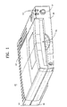
- the disk drive 40 comprises an outer housing 42 having top and bottom covers 44, 46 and a front panel 48.
- a disk cartridge can be inserted into the disk drive 40 through a horizontal opening 49 in the front panel 48 of the disk drive 40.
- a user-interface of the disk drive 40 comprises an eject button 51 for automatically ejecting a disk cartridge from the disk drive 40, and a plurality of drive status indicators 53 for indicating that the drive has power and for indicating that the drive is accessing a storage medium within the disk cartridge.
- the terms "access” and “accessing” means either writing to or reading from a storage medium, or both.
- the disk drive 40 is intended to interface with a host computer (not shown) and can be employed as a stand-alone unit, or alternatively, can be installed in an internal bay (not shown) of the host computer (not shown).
- Figures 2 and 3 show an exemplary disk cartridge 10 that can be inserted into the disk drive 40 of Figure 1.
- the disk cartridge 10 comprises an outer casing 12 having upper and lower shells 22, 24 that mate to form the casing.
- a disk-shaped storage medium described hereinafter is affixed to a hub 16 that is rotatably mounted within the casing 12.
- An opening 21 on the bottom shell 24 of the casing 12 provides access to the disk hub 16.
- a head access opening 30 in the front peripheral edge 20 of the disk cartridge 10 provides access to the surfaces of the storage medium by the read/write heads of the disk drive 40.
- a shutter 18 (not shown in Fig. 2) is provided on the front peripheral edge 20 of the disk cartridge 10 to cover the head access opening 30 when the cartridge 10 is not in use. When the cartridge is inserted into the disk drive 40, the shutter 18 moves to the side exposing the head access opening 30 and thereby providing the read/write heads of the drive with access to the storage medium within the disk cartridge.
- Figure 4 shows a disk-shaped storage medium 60 in accordance with a preferred embodiment of the present invention.
- the storage medium 60 comprises a disk having a magnetic coating for writing and reading information to and from the storage medium 60.
- information can be written on both sides of the storage medium 60.
- magnetic media is preferred, other media can be employed, and the present invention is by no means limited to use of magnetic storage media.
- the storage medium 60 can be a rewritable optical storage medium or a magneto-optical storage medium.
- the storage medium has a band of approximately 1800 concentric data tracks 62 which can be written to, and read from, by a user's host computer. Other track densities can be employed, however.
- the data tracks 62 there are two tracks 64, 66 on each side of the storage medium (only one side shown in Figure 4) that contain special information pertaining to the defect characteristics of that particular storage medium. The information contained on these four tracks (two per side) is identical and, in fact, is repeated in two separate locations on each track 64, 66. This redundancy is necessary to ensure that the information is always available, even if some areas of the storage medium become damaged and unreadable.
- one of these special information tracks i.e., track 64
- track 64 On each side of the storage medium 60, one of these special information tracks, i.e., track 64, is located at the outside of the band of data tracks 62, and the other special information track 66 is located to the inside of the band of data tracks 62. None of the four special information tracks 64, 66 can be accessed by a host computer (not shown) to which the disk drive 40 is interfaced. Only the disk drive 40, and in particular, a microprocessor within the disk drive 40, can access the information written on these tracks 64, 66.
- a first predetermined location is provided on the storage medium 60 for writing, or storing, a code having a value indicative of a protection mode of the storage medium.
- a second predetermined location is provided on the storage medium 60 for storing, if desired, a password associated with the code.
- the storage medium 60 can be subjected to one of four different protection modes. Each protection mode specifies a different way in which access to the data tracks 62 of the storage medium 60, i.e., writing and reading of information to and from the data tracks 62, may be inhibited.
- the four possible protection modes of a storage medium are:
- a "Temporary Unlock Mode", or command can be applied to the disk drive 40 to effectively override the protection mode of the storage medium specified by the code written in the first predetermined location on the storage medium.
- At least the outer special information track 64 on at least one side of the storage medium includes at least one write/read protect sector 68 that comprises an ID field 70 and a data field 72.
- the ID field 70 is used to identify the write/read protect sector 68 and to distinguish that sector from other sectors in the special information track 64.
- the data field 72 comprises 512 bytes, however, in other embodiments, the data field 72 may comprise a different number of bytes.
- a first portion of the data field 72 of the write/read protect sector 68 is used for writing, or storing, one of the aforementioned codes on the storage medium to indicate the current protection mode of the storage medium 60. This first portion of the write/read protect sector 68 defines the first predetermined location referred to above and in the claims.
- a second portion of the data field 72 of the write/read protect sector 68 is used for writing, or storing, a password on the storage medium 60. This second portion of the write/read protect sector 68 defines the second pre-determined location referred to above and in the claims.
- the content and arrangement of the data field 72 is as follows: BYTE # Description 0 Vendor Unique 1 Code indicating current protection mode of storage medium 2 Password Length 3-34 Password in ASCII Characters 35-511 Unused
- byte "0" of the data field 72 is used to provide a unique identifier of the vendor of the storage medium 60 and/or disk cartridge 10.
- Byte "1” is used to store one of the aforementioned codes in order to indicate the current protection mode applied to the storage medium 60.
- Bytes “3” through “34” hold the ASCII character representation of the password, if any, currently in effect.
- Byte "2" specifies the password length, in bytes.
- the password is used to prevent unauthorized changing of the protection mode specified by the code stored in byte "1", i.e., to prevent a new code from being written in place of the current code to which the password is associated.
- bytes "35” through “511" of the write/read protect sector 68 are unused in connection with the read/write protect scheme of the present invention.
- the write/read protect sector 68 is duplicated twice in each of the special information tracks 64, 66 on each side of the storage medium 60. This provides a total of eight identical write/read protect sectors 68 on the storage medium.
- the disk drive 40 can access any one of these eight duplicate write/read protect sectors 68 to determine the current protection mode of the storage medium, as well as to determined the current password, if any, associated with that protection mode. This redundancy is necessary to ensure that the code and password of the current protection mode can be ascertained, even if some areas of the storage medium 60 become damaged and unreadable.
- duplicate write/read protect sectors 68 are provided in respective ones of the special information tracks 64, 66, those sectors, like the remainder of each special information track 64, 66 are not accessible by the host computer to which the disk drive 40 is interfaced. Only the disk drive 40 can access the write/read protect sectors on the storage medium.
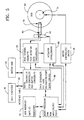
- FIG. 5 is a block diagram of the disk drive 40 in accordance with a preferred embodiment of the present invention.
- the disk drive 40 comprises a spindle motor 74, motor controller/driver 76, read/write heads 78, read/write preamp 80, read channel 84, actuator 82, actuator servo/driver 86, digital controller 88, random-access memory buffer 90, microprocessor 92 and user interface components 94, which include the status indicators 53 and ejection button 51 on the front panel 48 of the disk drive 40.
- the disk drive 40 connects to a user's host computer 96 through an interface cable 98.
- the motor controller/driver 76 and spindle motor 74 rotate the storage medium 60 at a constant speed, allowing the read/write heads 78 to "fly" close to the rotating storage medium 60 for a stable recording environment.
- the motor controller/driver 76 can be implemented, at least in part, with the 8902 series motor controller/driver available from Allegro Microsystems, Inc., 115 Northeast Cutoff, Worcester, Massachusetts 01615.
- the read/write preamp 80 amplifies the signals picked up by the heads 78 during read operations and switches current in the heads 78 during write operations.
- the read channel 84 shapes the pulses from the preamp, qualifies the peaks that represent the user data and special information, and generates a clock that is synchronous with the RLL (run length limited) data coming off the storage medium.
- the read channel 84 may be implemented, at least in part, with the AD899 series read channel electronics available from Analog Devices, One Technology Way, Norwood, MA 01062.
- the actuator 82 comprises a linear actuator, although the present invention is by no means limited thereto.
- a radial arm voice coil actuator can also be employed.
- the actuator servo/driver 86 demodulates servo information recorded on the storage medium and compensates to position the read/write heads 78 precisely on a selected track of the data storage medium 60.
- the actuator servo/driver 86 can be implemented, at least in part, with the 8932-A series driver available from Allegro Microsystems, Inc., 115 Northeast Cutoff, Worcester, Massachusetts 01615.
- the digital controller 88 decodes and error checks the data from the read channel 84 and stores the data temporarily in a buffer RAM. The controller 88 also makes sure that data is written to, or read from, the correct track and sector of the storage medium 60.
- the controller 88 when directed by the microprocessor 92, sends data from the buffer 90 to the host computer 96, or from the host computer 96 to the buffer 90, in accordance with a SCSI protocol.
- the digital controller 88 also generates servo control signals.
- the digital controller 88 can be implemented using the AIC-7110 High-Performance Integrated SCSI Mass Storage Controller available from Adaptec, 691 South Milpitas Blvd., Milpitas, CA 95035.
- the microprocessor 92 controls and monitors all functions in the drive.
- the program code is stored in a Read-Only Memory ("ROM"), while a RAM is used for storing variables, flags, status information, etc.
- ROM Read-Only Memory
- RAM Random Access Memory
- the microprocessor 92 is responsible, in large part, for performing the steps of the method of the present invention.
- a significant function of the microprocessor 92 is to control access, i.e. reading and writing, to the storage medium 60 in accordance with the protection mode indicated by the code stored, or written, in the first predetermined location on the storage medium, i.e., the code written in byte "1" of the data field 72 of each of the eight duplicate write/read protect sectors 68.
- Any suitable microprocessor can be employed, such as, for example, a Motorola 68HC16 microprocessor or an Intel 8032 microprocessor.
- the current protection mode of a storage medium 60 can be selected by a user of the host computer 96 at any time and can likewise be changed by the user at any time.
- Changing or setting the protection mode of a storage medium in accordance with the present invention is achieved by sending an appropriate "protection mode command" from the host computer 96 to the disk drive 40.
- the protection mode command has the following content and arrangement: Bit Byte 7 6 5 4 3 2 1 0 0 Operation Code (0Ch) 1 Protection Mode Code 2-3 Reserved 4 Password Length (0-32 characters) 5 Control Byte (00h)
- the protection mode command comprises six bytes.
- the Operation Code (“OpCode”) of the protection mode command occupies the first byte, i.e., byte "0", of the command.
- the OpCode for the protection mode command is 0C hex.
- Byte “1” of the command contains the code value indicative of the desired protection mode.
- Bytes “2” and “3” are reserved.
- Byte "5" is a control byte that, in the present embodiment, has a value of 00h.
- Byte "4" of the protection mode command specifies the length, in bytes, of any password sent by the host computer 96 immediately following the protection mode command.
- the maximum length of a password is 32 bytes. Any byte value from 00h to FFh is acceptable as a valid password character.
- the password sent with the protection mode command must identically match the password written in the second predetermined location on the storage medium. Otherwise, the protection mode command attempting to change the current protection mode will be rejected. Formatting the storage medium 60 allows the media to be recovered if the password is forgotten, but any stored data will be lost. A storage medium that is in the Read/Write Protect Mode will require that the format overwrite every host accessible sector on the storage medium before removing or allowing any change to that protection mode.
- the protection mode applies to the entire volume of information in the data tracks 62 on both sides of the storage medium. In other embodiments, however, provision may be made for protecting individual sectors or groups of sectors anywhere on the storage medium. Such an embodiment would require a separate code and password for each such individual sector or group of sectors.
- the microprocessor 92 (Fig. 5) is responsible for executing the protection mode command and for ensuring that the code value indicative of a desired protection mode and any password associated therewith are written to the storage medium.
- the microprocessor 92 compares the password sent from the host computer 96 with the password written in the duplicate write/read protect sectors 68 on the storage medium. If the password sent from the host computer 96 does not match the password written on the storage medium 60, the microprocessor will prevent any change in the protection mode.
- the microprocessor 92 is also responsible for inhibiting writing of information from the host computer to the data tracks 62 of the storage medium 60 when the current protection mode of the storage medium, as indicated by the code value written in the first predetermined location thereof, is either the Write-Protect Mode, Password Write Protect Mode or Read/Write Protect Mode. When the current protection mode is the Read/Write Protect Mode, the microprocessor 92 will also inhibit reading of information from the data storage medium.
- the protection mode command described above can also be used to put the disk drive 40 in a Temporary Unlock Mode. In the present embodiment, this is accomplished by sending the protection mode command with a code value of "0000 1xxx", where "x" indicates either a "1" or "0". Upon receiving a protection mode command having this code value, the microprocessor 92 will temporarily disable all read and write protection for the storage medium until either the current disk cartridge is removed from the disk drive, or power to the drive is turned off.
- the Temporary Unlock Mode does not change or affect the code value and password, if any, stored in the first and second predetermined locations on the storage medium.
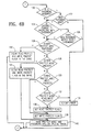
- Figure 6 is flow diagram illustrating both the operation of the disk drive 40 of Figure 5, particularly microprocessor 92, and a preferred embodiment of the method of the present invention.
- the microprocessor 92 waits at step 102 until the insertion of a disk cartridge into the disk drive 40 is detected.
- detection of a disk cartridge is achieved in accordance with the methods and apparatus described in co-pending application Serial No. 08/337,678, filed November 10, 1994, entitled “Disk Cartridge Detection Methods and Apparatus".
- control passes to step 104.
- the microprocessor 92 reads the code value and password, if any, stored in the first and second predetermined locations on the storage medium 60, i.e., bytes 1 and 3-34 of the data field 72 of at least one of the eight duplicate write/read protect sectors 68.
- the code value read from the storage medium defines a first, or initial code, and indicates the first, or initial, protection mode of the storage device.
- the microprocessor 92 examines the first code to determine whether the storage medium is read protected, which in the present embodiment, only applies when the protection mode of the storage medium is the Read/Write Protect Mode. If the first code indicates that the storage medium is read protected, i.e., the storage medium is in the Read/Write Protect Mode, then control passes to step 108 where the microprocessor 92 sets an internal "read protect" flag to indicate that the storage medium is read protected. The microprocessor 92 thereafter inhibits any attempt by the user's host computer to read information from the storage medium 60. Any such attempt results in an error message being sent to the host computer.
- step 110 the microprocessor 92 examines the first code to determine whether the storage medium is any of the modes that provide write protection, i.e., the Write Protect Mode, the Password Write Protect Mode or the Read/Write Protect Mode. If the first code represents either of these modes, then control passes to step 112 where the microprocessor 92 sets an internal "write protect" flag to indicate that the storage medium 60 is write protected. The microprocessor 92 thereafter inhibits any attempt by the user's host computer to write information to the storage medium 60. Any such attempt results in an error message being sent to the host computer.
- step 110 determines in step 110 that the storage medium 60 is not write protected
- step 114 the microprocessor 92 determines whether the current disk cartridge has been removed from the disk drive 40. If not, control passes to step 118 where the microprocessor 92 inquires whether a protection mode command has been received from the host computer 96. If not, control passes back to step 114. Normal operation of the disk drive 40 can then proceed. The microprocessor periodically will perform steps 114 and 118. Normal operation will continue until either the current disk cartridge is removed (step 114), or a protection mode command is received from the host computer requesting a change in the protection mode of the storage medium (step 118).
- step 120 the microprocessor 92 determines whether a password should have been sent with the protection mode command either (i) because the new protection mode to be established is one of the password-protected modes, e.g., the Password Write Protect Mode or the Read/Write Protect Mode, or (ii) because the current protection mode is one of the password protected modes and thus requires a password to change from that mode. If, for either of these reasons, the new protection mode does require a password, control passes to step 122 where the microprocessor determines whether a password was sent immediately following the protection mode command. If not, control passes to step 134 where an error is reported. Control will then pass from step 134 back to step 114.
- the new protection mode to be established is one of the password-protected modes, e.g., the Password Write Protect Mode or the Read/Write Protect Mode, or (ii) because the current protection mode is one of the password protected modes and thus requires a password to change from that mode. If, for either of these reasons, the new protection mode does require
- the new code value in the protection mode command defines a second code, and the new protection mode specified by that second code defines a second protection mode.
- the microprocessor 92 examines the first code, which is still stored in the first predetermined location on the storage medium, to determine if the first, or current, protection mode requires a password before a change in protection mode can be effected. If a password is required to change from the current protection mode, control passes to step 126 where the microprocessor compares the password that accompanied the protection mode command with the current password read from the second predetermined location on the storage medium. If these passwords do not match identically, then control passes from step 126 to step 134 where an appropriate error is reported. Control then passes from step 134 back to step 114.
- the microprocessor 92 determines whether the second code transmitted in the protection mode command represents the Temporary Unlock Mode. If the second code does not represent the Temporary Unlock Mode, then control passes to step 129. At step 129, the microprocessor 92 examines the new, or second code, is the code for the Unlock Mode. If so, control passes to step 131 where the read protect and write protect flags are cleared in accordance with the Unlock Mode. Control then passes to step 140 where the new, or second code, representing the Unlock Mode is written to the first predetermined location on the storage medium in place of the first code. Information may also be stored in the second predetermined location to indicate that no password is provided with this protection mode. At this point, the change from the first protection mode to the second protection mode has been effected. Control will then pass back to step 114.
- step 130 the microprocessor determines whether the second code is the code for either the Write Protect Mode or the Password Write Protect Mode. If so, control passes to step 138 where the write protect flag is set.
- step 140 the second code and password, if any, are written to the first and second predetermined locations on the storage medium, respectively, in place of the first code and its associated password, if any. At this point, the change from the first protection mode to the new, or second protection mode has been effected. Control will then pass back to step 114.
- step 130 If, however, it is determined at step 130 that the second code does not represent either the Write Protect Mode or the Password Write Protect Mode, then control passes to step 132 where it is determined whether the second code has the value representing the Read/Write Protect Mode. If so, control will pass successively to steps 136 and 138 where both the read and write protect flags will be set. Control will then pass to step 140 where the new, or second code, and any associated password are written to the first and second predetermined locations on the storage medium, respectively, in place of the first code and its associated password, if any. At this point, the change from the first protection mode to the second protection mode has been effected. Control will then pass back to step 114.
- step 132 If it is determined at step 132 that the second code does not represent the Read/Write Protect Mode, then the disk drive assumes that an erroneous code value was sent. Control will therefore pass to step 134 where an error will be reported to the host computer. After reporting the error, control will pass back to step 114. No change in the protection mode of the storage medium will have been effected.
- step 128 it is determined that the code value of the protection mode command (i.e., the new or second code) is the code for the Temporary Unlock Command, control passes to step 142 where both the read and write protect flags are reset. This effectively unlocks any read or write protection afforded by the current protection mode. Control will then pass back to step 114. Step 140 will have been by-passed, and therefore, the first code and its associated password, if any, are not overwritten or destroyed. Writing and reading of information to and from the storage medium will, however, no longer be inhibited. The disk drive 40 will operate in this Temporary Unlock Mode until either the disk cartridge is removed, or another protection mode command is sent to again change or reestablish the first, or current protection mode within the drive.
- the code value of the protection mode command i.e., the new or second code
- the present invention is directed to a method for inhibiting the writing and reading of information to and from a storage medium without the need for mechanical, electrical or other types of switches used in prior art write protect schemes. Additionally, both read and write protection may be password protected to prevent unauthorized changes in protection mode. Since the write and read protection functions, including password comparison are accomplished by the microprocessor inside the drive, rather than by the operating system of a host computer, they are more resistant to tampering.
Description
| CODE VALUE (binary) | PROTECTION MODE |
| 0000 0000 | Unlock Mode |
| 0000 0010 | Write Protect Mode |
| 0000 0011 | Password Write Protect Mode |
| 0000 0101 | Read/Write Protect Mode |
| BYTE # | Description |
| 0 | |
| 1 | Code indicating current protection mode of |
| 2 | Password Length |
| 3-34 | Password in ASCII Characters |
| 35-511 | Unused |
| Bit | ||||||||
| Byte | 7 | 6 | 5 | 4 | 3 | 2 | 1 | 0 |
| 0 | Operation Code (0Ch) | |||||||
| 1 | Protection Mode Code | |||||||
| 2-3 | Reserved | |||||||
| 4 | Password Length (0-32 characters) | |||||||
| 5 | Control Byte (00h) |
Claims (27)
- A method of inhibiting inadvertent or unauthorized writing and/or reading of information to and from a removable storage medium (60) according to one of several read/write protection modes, comprising the steps ofwriting (140) a first code in a predetermined location on the removable storage medium, said first code being indicative of a first protection mode of said storage medium, said first code being one of code values assigned to represent each of the protection modes;writing a password in a second predetermined location on said storage medium;receiving a command to change the protection mode of said storage medium from said first protection mode to a second protection mode; and in response to the command;writing in said predetermined location on the storage medium, in place of the first code, a second code indicative of the second protection mode, said second code being one of code values assigned to represent each of the protection modes, said writing of a second code being only performed if a password received with said command matches (126) the password written in the second predetermined location on said storage medium.
- The method recited in claim 1 wherein said first and second protection modes comprise one of a protection wherein writing of information to the storage medium is inhibited, a protection mode wherein writing and reading of information to and from the storage medium (60) are not inhibited, and a protection mode wherein both writing and reading of information to and from the storage medium are inhibited.
- The method recited in claim 1 or 2, further comprising the steps of:reading (104) an initial code written in the predetermined location on said storage medium upon insertion of the storage medium into a disk drive;determining (106) from the initial code an initial protection mode of said storage medium; andsetting (136, 138) at least one flag internal to the disk drive to indicate the initial protection mode of said storage medium.
- The method recited in claim 1, 2 or 3, further comprising the step (108, 112) of generating an error signal whenever access to the storage medium is attempted in a manner that is inhibited in accordance with the protection mode indicated by the code written in the predetermined location on said storage medium.
- The method recited in one of claims 1 to 4, wherein the method is carried out in a disk drive (40) of the type that receives a removable cartridge (10) containing a disk storage medium (60) for reading and writing information thereto, said disk drive being responsive to said first code to inhibit access to said storage medium in accordance with the first protection mode indicated by said first code.
- The method recited in claim 5, further comprising the steps of:reading (104) the first code written in the predetermined location on said storage medium upon insertion of the storage medium into the disk drive;determining (106) from the first code the first protection mode of said storage medium; andsetting (136, 138) at least one flag internal to the disk drive to indicate the first protection mode of the storage medium.
- The method recited in claim 6 further comprising the steps of:receiving a command to temporarily by-pass the protection mode indicated by the code written in the predetermined location on said storage medium; andresetting (142) said flag to a state that indicates that access to the storage medium is not inhibited, whereby the disk drive can thereupon access the storage medium in a manner that would otherwise be inhibited in accordance with the protection mode indicated by the code written in the predetermined location without having to write a new code in the predetermined location.
- The method recited in claim 5, 6 or 7, further comprising the step (108, 112) of generating an error signal whenever access to the storage medium is attempted in a manner that is inhibited in accordance with the protection mode indicated by the code written in the predetermined location on said storage medium.
- A cartridge (10) comprising a disk storage medium (60) having a plurality of concentric tracks to and from which information may be written and read by a disk drive, the disk storage medium having written, in a first predetermined location thereon, a code that indicates a protection mode of said disk storage medium, said code being one of code values assigned to represent each of several read/write protection modes,
characterised in that a password is written in a second predetermined location on said disk storage medium, and is associated with said code for allowing writing of another code in place of the code written in said first predetermined location. - The cartridge recited in claim 9 wherein the protection mode indicated by the code written in said first predetermined location comprises one of a protection mode wherein writing of information to the disk storage medium is inhibited, a protection mode wherein writing and reading of information to and from the disk storage medium are not inhibited, and a protection mode wherein both writing and reading of information to and from the disk storage medium are inhibited.
- The cartridge recited in claim 9 or 10, wherein said first and second predetermined locations are duplicated at a plurality of positions (64, 66) on said disk storage medium (60).
- The cartridge recited in one of claims 9 to 11, wherein said first and second predetermined locations are duplicated on opposite surfaces of said disk storage medium (60).
- The cartridge recited in one of claims 9 to 12, wherein said first and second predetermined locations are part of at least one concentric track (64, 66) on said disk storage medium (60) that is not accessible by a host computer interfaced to said drive.
- The cartridge recited in one of claims 9 to 13, wherein said disk storage medium (60) comprises one of a magnetic storage medium, a rewritable optical storage medium and a magneto-optical storage medium.
- The cartridge according to one of claims 9 to 14, wherein said concentric tracks comprise approximately 1800 concentric data tracks (62).
- The cartridge according to one of claims 13 to 15, wherein said disk storage medium has two tracks (64, 66) not accessible by a host computer interfaced to said drive, on each side of the disk storage medium.
- The cartridge according to one of claims 13 to 16, wherein said disk storage medium has one track (64) not accessible by a host computer interfaced to said drive, at the outside of said data tracks (62).
- The cartridge according to one of claims 13 to 17, wherein said disk storage medium has one track (66) not accessible by a host computer interfaced to said drive, at the inside of said data tracks (62).
- The cartridge according to one of claims 9 to 18, wherein said disk storage medium has at least one track (64) not accessible by a host computer interfaced to said drive, including at least one write/read protect sector (68) comprising an ID field (70) and a data field (72), said ID field identifying (70) the write/read protect sector and distinguishing this sector from other sectors on said track (64).
- The cartridge according to claim 19, wherein the data field (72) comprised 512 bytes.
- The cartridge according to claim 19 or 20, wherein a first portion of the data field (72) defines said first predetermined location.
- The cartridge according to claim 19, 20 or 21, wherein a second portion of the data field (72) defines said second predetermined location.
- The cartridge according to one of claims 19 to 22, wherein the data field has the following contents and arrangement:byte # 1: identifier of the vendor of the storage medium;byte # 2: code indicating a protection mode;byte # 3: password length;bytes # 3-34: password in ASCII characters;bytes # 35-511: unused.
- The cartridge according to one of claims 9 to 23, wherein said code has a binary value of "0000 0000" to indicate an unlock mode.
- The cartridge according to one of claims 9 to 24, wherein said code has a binary value of "0000 0010" to indicate write protect mode.
- The cartridge according to one of claims 9 to 25, wherein said code has a binary value of "0000 0011" to indicate write password protect mode.
- The cartridge according to one of claims 9 to 26, wherein said code has a binary value of "0000 0101" to indicate read/write protect mode.
Priority Applications (1)
| Application Number | Priority Date | Filing Date | Title |
|---|---|---|---|
| EP01201140A EP1132910A3 (en) | 1995-03-10 | 1996-03-01 | Read/write protect scheme for a disk cartridge and drive |
Applications Claiming Priority (3)
| Application Number | Priority Date | Filing Date | Title |
|---|---|---|---|
| US08/402,540 US5644444A (en) | 1995-03-10 | 1995-03-10 | Read/write protect scheme for a disk cartridge and drive |
| US402540 | 1995-03-10 | ||
| PCT/US1996/002766 WO1996028820A1 (en) | 1995-03-10 | 1996-03-01 | Read/write protect scheme for a disk cartridge and drive |
Related Child Applications (1)
| Application Number | Title | Priority Date | Filing Date |
|---|---|---|---|
| EP01201140A Division EP1132910A3 (en) | 1995-03-10 | 1996-03-01 | Read/write protect scheme for a disk cartridge and drive |
Publications (3)
| Publication Number | Publication Date |
|---|---|
| EP0789908A1 EP0789908A1 (en) | 1997-08-20 |
| EP0789908A4 EP0789908A4 (en) | 1997-09-24 |
| EP0789908B1 true EP0789908B1 (en) | 2001-05-30 |
Family
ID=23592335
Family Applications (2)
| Application Number | Title | Priority Date | Filing Date |
|---|---|---|---|
| EP01201140A Withdrawn EP1132910A3 (en) | 1995-03-10 | 1996-03-01 | Read/write protect scheme for a disk cartridge and drive |
| EP96908583A Expired - Lifetime EP0789908B1 (en) | 1995-03-10 | 1996-03-01 | Read/write protect scheme for a disk cartridge and drive |
Family Applications Before (1)
| Application Number | Title | Priority Date | Filing Date |
|---|---|---|---|
| EP01201140A Withdrawn EP1132910A3 (en) | 1995-03-10 | 1996-03-01 | Read/write protect scheme for a disk cartridge and drive |
Country Status (6)
| Country | Link |
|---|---|
| US (3) | US5644444A (en) |
| EP (2) | EP1132910A3 (en) |
| JP (1) | JPH10504420A (en) |
| CA (1) | CA2211590C (en) |
| DE (2) | DE789908T1 (en) |
| WO (1) | WO1996028820A1 (en) |
Families Citing this family (91)
| Publication number | Priority date | Publication date | Assignee | Title |
|---|---|---|---|---|
| MY121551A (en) | 1994-12-22 | 2006-02-28 | Sony Corp | Recording and reproducing system for protecting copyrighted data |
| US6490113B2 (en) | 1994-12-22 | 2002-12-03 | Sony Corporation | Recording medium and apparatus for protecting copyrighted digital data |
| US5644444A (en) * | 1995-03-10 | 1997-07-01 | Iomega Corporation | Read/write protect scheme for a disk cartridge and drive |
| US6724554B1 (en) | 1995-03-10 | 2004-04-20 | Iomega Corporation | Read/write protect scheme for a disk cartridge and drive |
| MY112755A (en) * | 1995-06-06 | 2001-08-30 | Sony Corp | Information data reproducing system, reproducing apparatus, reproducing method, data forming apparatus and data record medium |
| JPH0964770A (en) * | 1995-08-18 | 1997-03-07 | Matsushita Electric Ind Co Ltd | Tuner integrally receiving ground broadcasting and satellite broadcasting |
| US6430363B2 (en) * | 1995-09-11 | 2002-08-06 | Matsushita Electric Industrial Co., Ltd. | Video signal recording and reproducing apparatus |
| JPH1049986A (en) * | 1996-08-05 | 1998-02-20 | Sony Corp | Recording medium, recorder or reproducer or reproducing method |
| US6747930B1 (en) | 1996-12-24 | 2004-06-08 | Hide & Seek Technologies, Inc. | Data protection on an optical disk |
| BE1011053A3 (en) * | 1997-03-21 | 1999-04-06 | Wang Wei Dong | Security process for access control to the disk of a double sided quadruple density diskette |
| US6072666A (en) | 1997-05-30 | 2000-06-06 | Iomega Corporation | Head retraction system for retracting the heads of a disk drive |
| JP3045410U (en) * | 1997-07-17 | 1998-02-03 | 船井テクノシステム株式会社 | Disk drive device |
| JPH11161552A (en) * | 1997-11-28 | 1999-06-18 | Fujitsu Ltd | Data protecting method for reloadable storage medium and storage device applied therewith |
| JP3454700B2 (en) * | 1998-01-20 | 2003-10-06 | 富士通株式会社 | Information storage device and control method thereof |
| EP1211681B1 (en) * | 1998-01-20 | 2007-02-14 | Fujitsu Limited | Data storage device and control method therefor |
| US6765853B1 (en) | 1998-06-15 | 2004-07-20 | Samsung Electronics Co., Ltd. | Recording medium for storing write protection information and write protection method thereof |
| KR100601598B1 (en) | 1998-06-15 | 2006-07-14 | 삼성전자주식회사 | Recording medium storing write protection information and write protecting method |
| EP1306841A3 (en) | 1998-06-15 | 2007-05-23 | Samsung Electronics Co., Ltd. | Recording medium for storing write protection information and write protection method thereof |
| US6259575B1 (en) * | 1998-07-01 | 2001-07-10 | Iomega Corporation | Readable indelible mark on storage media |
| US9361243B2 (en) | 1998-07-31 | 2016-06-07 | Kom Networks Inc. | Method and system for providing restricted access to a storage medium |
| US8234477B2 (en) | 1998-07-31 | 2012-07-31 | Kom Networks, Inc. | Method and system for providing restricted access to a storage medium |
| CA2244626A1 (en) * | 1998-07-31 | 2000-01-31 | Kom Inc. | A hardware and software system |
| US7536524B2 (en) * | 1998-07-31 | 2009-05-19 | Kom Networks Inc. | Method and system for providing restricted access to a storage medium |
| TR200002369T1 (en) * | 1998-10-05 | 2001-01-22 | Koninklijke Philips Electronics N.V. | Process for copy protection of recorded information. |
| US6583945B1 (en) * | 1998-10-30 | 2003-06-24 | Iomega Corporation | Method for irreversibly write-securing a magnetic storage cartridge |
| US6459544B1 (en) | 1998-11-20 | 2002-10-01 | Bruce M. Harper | Removable cartridge for data-storage medium |
| JP2000222863A (en) * | 1999-01-28 | 2000-08-11 | Pioneer Electronic Corp | Storage medium and recording/reproducing device |
| US6560192B1 (en) * | 1999-03-19 | 2003-05-06 | Terastor Corporation | Method and apparatus for dampening disk vibrations |
| BR0010777A (en) * | 1999-03-23 | 2002-01-15 | Matsushita Electric Ind Co Ltd | Multi-layered rewritable disc and information recording / playback device for that disc |
| JP3758886B2 (en) | 1999-03-30 | 2006-03-22 | 富士通株式会社 | Data processing apparatus and access control method thereof |
| US6330210B1 (en) * | 1999-04-29 | 2001-12-11 | Hewlett-Packard Company | Data structure for control information on rewriteable data storage media |
| US6580683B1 (en) | 1999-06-23 | 2003-06-17 | Dataplay, Inc. | Optical recording medium having a master data area and a writeable data area |
| US7227817B1 (en) | 1999-12-07 | 2007-06-05 | Dphi Acquisitions, Inc. | Low profile optical head |
| US6104048A (en) * | 1999-06-30 | 2000-08-15 | Iomega Corporation | Electrostatic discharge protection for magneto-resistive heads |
| JP2001023301A (en) | 1999-07-09 | 2001-01-26 | Fujitsu Ltd | Storage device and device and method for controlling access to recording medium |
| JP2001023300A (en) | 1999-07-09 | 2001-01-26 | Fujitsu Ltd | Storage device, control device and method for accessing to recording medium |
| DE19937060A1 (en) * | 1999-08-05 | 2001-02-15 | Siemens Pc Systeme Gmbh & Co K | Procedure to protect computer peripheral data carrier device, CD-ROM drive, CD writer, DVD-ROM |
| US6631359B1 (en) | 1999-09-10 | 2003-10-07 | Dphi Acquisitions, Inc. | Writeable medium access control using a medium writeable area |
| US7191153B1 (en) | 1999-09-10 | 2007-03-13 | Dphi Acquisitions, Inc. | Content distribution method and apparatus |
| US7225809B1 (en) * | 1999-11-01 | 2007-06-05 | Ric Investments, Llc | Method and apparatus for monitoring and controlling a medical device |
| US8230190B1 (en) | 1999-11-22 | 2012-07-24 | Seagate Technology Llc | Storage device with built-in data security system |
| NL1014274C2 (en) * | 2000-02-03 | 2001-08-16 | Tele Atlas Bv | System for securing data present on a data carrier. |
| JP2001312374A (en) * | 2000-04-28 | 2001-11-09 | Fujitsu Ltd | Storage device and access control method |
| US6598135B1 (en) * | 2000-05-03 | 2003-07-22 | Plasmon Ide | System and method for defining rewriteable data storage media as write once data storage media |
| US6393539B1 (en) * | 2000-05-04 | 2002-05-21 | Dell Products, L.P. | System and method for reliably assigning and protecting data in a centralizes storage system |
| US6738879B2 (en) * | 2000-05-22 | 2004-05-18 | Seagate Technology Llc | Advanced technology attachment compatible disc drive write protection scheme |
| US6717764B2 (en) | 2000-06-02 | 2004-04-06 | Seagate Technology Llc | Method and apparatus for head fly height measurement |
| US20050063256A1 (en) * | 2000-06-30 | 2005-03-24 | Selinfreund Richard H. | Data storage in optical discs |
| WO2002002301A1 (en) | 2000-06-30 | 2002-01-10 | Verification Technologies Inc. | Copy-protected optical media and method of manufacture thereof |
| US6638593B2 (en) | 2000-06-30 | 2003-10-28 | Verification Technologies, Inc. | Copy-protected optical media and method of manufacture thereof |
| US8635410B1 (en) * | 2000-07-20 | 2014-01-21 | Silicon Graphics International, Corp. | System and method for removing data from processor caches in a distributed multi-processor computer system |
| JP3998405B2 (en) * | 2000-07-28 | 2007-10-24 | 富士通株式会社 | Access control method and storage device using the same |
| US7660415B2 (en) | 2000-08-03 | 2010-02-09 | Selinfreund Richard H | Method and apparatus for controlling access to storage media |
| US7539828B2 (en) * | 2000-08-08 | 2009-05-26 | Faronics Corporation | Method and system for automatically preserving persistent storage |
| GB2369202B (en) * | 2000-08-31 | 2003-03-19 | Sun Microsystems Inc | Computer system and method of operating a computer system |
| JP4770012B2 (en) * | 2000-10-06 | 2011-09-07 | ソニー株式会社 | Memory device |
| US7036020B2 (en) * | 2001-07-25 | 2006-04-25 | Antique Books, Inc | Methods and systems for promoting security in a computer system employing attached storage devices |
| US7925894B2 (en) * | 2001-07-25 | 2011-04-12 | Seagate Technology Llc | System and method for delivering versatile security, digital rights management, and privacy services |
| US7865440B2 (en) * | 2001-10-11 | 2011-01-04 | International Business Machines Corporation | Method, system, and program for securely providing keys to encode and decode data in a storage cartridge |
| US7003111B2 (en) * | 2001-10-11 | 2006-02-21 | International Business Machines Corporation | Method, system, and program, for encoding and decoding input data |
| US6904495B2 (en) * | 2002-01-10 | 2005-06-07 | Hewlett-Packard Development Company, L.P. | Method for identifying the write protect status of a diskette |
| US6739515B1 (en) | 2002-05-09 | 2004-05-25 | Sandisk Corporation | Low-cost write protect tab for a non-volatile memory device |
| AU2003228985A1 (en) * | 2002-05-09 | 2003-11-11 | Kestrel Wireless, Inc. | Method and system for enabling electronic transactions via a personal device |
| JP2004220756A (en) * | 2002-12-27 | 2004-08-05 | Konica Minolta Holdings Inc | Data recording program, information recording medium and data recording terminal, data recording system, and data recording method |
| WO2005001524A2 (en) * | 2003-06-23 | 2005-01-06 | Kestrel Wireless, Inc. | Method and apparatus for activating optical media |
| JP2005063483A (en) * | 2003-08-12 | 2005-03-10 | Pioneer Electronic Corp | Information recording/reproducing device, information recording/reproducing method and information recording/reproducing program |
| US7213118B2 (en) * | 2003-09-29 | 2007-05-01 | International Business Machines Corporation | Security in an automated data storage library |
| US7224545B2 (en) * | 2004-04-15 | 2007-05-29 | Quantum Corporation | Methods and systems for overwrite protected storage media |
| US20060002246A1 (en) * | 2004-06-30 | 2006-01-05 | International Business Machines Corporation | Sector-based worm implementation on random access memory |
| EP1810440A2 (en) * | 2004-10-26 | 2007-07-25 | Kestrel Wireless, Inc. | Method, system, and network for selectively controlling the utility a target |
| US20070194945A1 (en) * | 2004-12-07 | 2007-08-23 | Paul Atkinson | Mobile Device for Selectively Activating a Target and Method of Using Same |
| US20060123055A1 (en) * | 2004-12-07 | 2006-06-08 | Paul Atkinson | Device and method for selectively controlling the utility of a target |
| US20060192653A1 (en) * | 2005-02-18 | 2006-08-31 | Paul Atkinson | Device and method for selectively controlling the utility of an integrated circuit device |
| CN102157177A (en) * | 2005-06-30 | 2011-08-17 | 皇家飞利浦电子股份有限公司 | Small cartridge free optical disc with high level of redundancy and tolerance for missing data |
| US7273181B2 (en) * | 2005-07-06 | 2007-09-25 | Kestrel Wireless, Inc. | Device and method for authenticating and securing transactions using RF communication |
| US20070008169A1 (en) * | 2005-07-11 | 2007-01-11 | Conero Ronald S | A Radio Frequency Activated Integrated Circuit and Method of Disabling the Same |
| US20070013603A1 (en) * | 2005-07-13 | 2007-01-18 | Paul Atkinson | Antenna devices and processes for improved rf communication with target devices |
| US20070143774A1 (en) * | 2005-07-29 | 2007-06-21 | Anoop Agrawal | Structures and processes for controlling access to optical media |
| WO2007047841A2 (en) * | 2005-10-18 | 2007-04-26 | Kestrel Wireless Inc. | Activation confirmation feedback circuits and methods |
| US7685389B2 (en) * | 2005-10-21 | 2010-03-23 | International Business Machines Corporation | Apparatus, system, and method for setting protection states of protected partitions in storage media |
| WO2007085016A2 (en) * | 2006-01-20 | 2007-07-26 | Kestrel Wireless Inc. | Optical media with reduced areal-sized optical shutters |
| US8429724B2 (en) | 2006-04-25 | 2013-04-23 | Seagate Technology Llc | Versatile access control system |
| US8028166B2 (en) * | 2006-04-25 | 2011-09-27 | Seagate Technology Llc | Versatile secure and non-secure messaging |
| US7539890B2 (en) * | 2006-04-25 | 2009-05-26 | Seagate Technology Llc | Hybrid computer security clock |
| US20080046114A1 (en) * | 2006-08-15 | 2008-02-21 | White Charles A | System, packaging, and method for distributing products |
| US20080046997A1 (en) * | 2006-08-21 | 2008-02-21 | Guardtec Industries, Llc | Data safe box enforced by a storage device controller on a per-region basis for improved computer security |
| US20080127348A1 (en) * | 2006-08-31 | 2008-05-29 | Kenneth Largman | Network computer system and method using thin user client and virtual machine to provide immunity to hacking, viruses and spy ware |
| US8085501B2 (en) | 2008-01-29 | 2011-12-27 | Imation Corp. | Reader including an interposer that prevents coupling with write-protected data cartridges |
| US20100042782A1 (en) * | 2008-08-18 | 2010-02-18 | Amiram Grynberg | Secure Portable File Storage Device |
| US8590060B2 (en) | 2010-10-08 | 2013-11-19 | Tandberg Data Holdings S.A.R.L. | Virtual removable disk device for removable storage media |
| US10782893B2 (en) * | 2017-02-22 | 2020-09-22 | International Business Machines Corporation | Inhibiting tracks within a volume of a storage system |
Family Cites Families (84)
| Publication number | Priority date | Publication date | Assignee | Title |
|---|---|---|---|---|
| US3828327A (en) * | 1973-04-30 | 1974-08-06 | Ibm | Simplified storage protection and address translation under system mode control in a data processing system |
| US3890601A (en) * | 1974-03-11 | 1975-06-17 | Philco Ford Corp | Password operated system for preventing unauthorized or accidental computer memory alteration |
| DE2838063A1 (en) * | 1978-08-31 | 1980-03-13 | Siemens Ag | TEXT EDITING DEVICE |
| JPS6343643Y2 (en) * | 1980-12-16 | 1988-11-14 | ||
| US4593353A (en) * | 1981-10-26 | 1986-06-03 | Telecommunications Associates, Inc. | Software protection method and apparatus |
| US4458315A (en) * | 1982-02-25 | 1984-07-03 | Penta, Inc. | Apparatus and method for preventing unauthorized use of computer programs |
| US4462076A (en) * | 1982-06-04 | 1984-07-24 | Smith Engineering | Video game cartridge recognition and security system |
| US4785361A (en) * | 1982-11-08 | 1988-11-15 | Vault Corporation | Method and apparatus for frustrating the unauthorized copying of recorded data |
| US4680731A (en) * | 1983-03-17 | 1987-07-14 | Romox Incorporated | Reprogrammable cartridge memory with built-in identification circuitry and programming method |
| JPS59175064A (en) * | 1983-03-23 | 1984-10-03 | Mitsubishi Electric Corp | Magnetic disk control system |
| US4734796A (en) * | 1983-04-14 | 1988-03-29 | Amiram Grynberg | Technique for preventing unauthorized copying of information recorded on a recording medium and a protected recording medium |
| JPS60107155A (en) * | 1983-11-16 | 1985-06-12 | Hitachi Ltd | Data protection system of storage volume |
| US4740890A (en) * | 1983-12-22 | 1988-04-26 | Software Concepts, Inc. | Software protection system with trial period usage code and unlimited use unlocking code both recorded on program storage media |
| US4577289A (en) * | 1983-12-30 | 1986-03-18 | International Business Machines Corporation | Hardware key-on-disk system for copy-protecting magnetic storage media |
| US4606016A (en) * | 1984-02-08 | 1986-08-12 | Optical Storage International | Write protection and data detection using differential detector |
| JPS60189531A (en) * | 1984-03-09 | 1985-09-27 | Fujitsu Ltd | Data protection processing system |
| US4748561A (en) * | 1984-05-14 | 1988-05-31 | Mark Brown | Method of protecting computer software |
| JPS60246451A (en) * | 1984-05-22 | 1985-12-06 | Sharp Corp | Information protecting device |
| US4823210A (en) * | 1984-08-13 | 1989-04-18 | Verbatim Corporation | Copy protected disk |
| US4644493A (en) * | 1984-09-14 | 1987-02-17 | International Business Machines Corporation | Implementing a shared higher level of privilege on personal computers for copy protection of software |
| DE3512785A1 (en) * | 1985-04-10 | 1986-10-23 | Telefonbau Und Normalzeit Gmbh, 6000 Frankfurt | Method for access protection |
| US4860128A (en) * | 1985-04-24 | 1989-08-22 | Nintendo Co., Ltd. | Recordable data device having identification symbols formed thereon and cooperating data processing system having registering symbols |
| JPS61275948A (en) * | 1985-05-31 | 1986-12-06 | Casio Comput Co Ltd | Data storage device |
| US4858036A (en) * | 1986-08-04 | 1989-08-15 | Peter Ginkel | Software protection and identification system |
| US4980782A (en) * | 1985-06-03 | 1990-12-25 | Peter Ginkel | Software protection and identification system |
| US4849836A (en) * | 1985-06-07 | 1989-07-18 | Software Heaven, Inc. | Copy protection for computer discs |
| CA1270339A (en) * | 1985-06-24 | 1990-06-12 | Katsuya Nakagawa | System for determining a truth of software in an information processing apparatus |
| US4757533A (en) * | 1985-09-11 | 1988-07-12 | Computer Security Corporation | Security system for microcomputers |
| JPH074449B2 (en) * | 1985-10-04 | 1995-01-25 | 任天堂株式会社 | Cartridge for game machine and game machine using the same |
| JPS62260244A (en) * | 1986-05-06 | 1987-11-12 | Nintendo Co Ltd | Memory cartridge |
| JP2771808B2 (en) * | 1986-12-27 | 1998-07-02 | ソニー株式会社 | recoding media |
| JP3025502B2 (en) * | 1987-03-16 | 2000-03-27 | 日立マクセル株式会社 | Semiconductor memory device |
| US4866769A (en) * | 1987-08-05 | 1989-09-12 | Ibm Corporation | Hardware assist for protecting PC software |
| US5185792A (en) * | 1988-02-10 | 1993-02-09 | Matsushita Electric Industrial Co., Ltd. | Recording and reproducing apparatus with limited digital copying |
| US5231546A (en) * | 1988-02-10 | 1993-07-27 | Matsushita Electric Industrial Co., Ltd. | Recording and reproducing apparatus with limited digital copying |
| JPH01208762A (en) * | 1988-02-15 | 1989-08-22 | Hitachi Ltd | Read/write protect control system |
| US4983816A (en) * | 1988-02-24 | 1991-01-08 | Kabushiki Kaisha Toshiba | Portable electronic device |
| JPH01296361A (en) * | 1988-05-25 | 1989-11-29 | Mitsubishi Electric Corp | Memory card |
| JPH01309120A (en) * | 1988-06-07 | 1989-12-13 | Nec Corp | Medium protection control system |
| JP2695855B2 (en) * | 1988-08-26 | 1998-01-14 | 株式会社東芝 | Portable electronic devices |
| US5161256A (en) * | 1988-08-26 | 1992-11-03 | Kabushiki Kaisha Toshiba | Method and system for allocating file area in memory area of ic card |
| US5144660A (en) * | 1988-08-31 | 1992-09-01 | Rose Anthony M | Securing a computer against undesired write operations to or read operations from a mass storage device |
| JP2504137B2 (en) * | 1988-09-27 | 1996-06-05 | 日本電気株式会社 | Memory write protect circuit |
| US4984272A (en) * | 1988-11-30 | 1991-01-08 | At&T Bell Laboratories | Secure file handling in a computer operating system |
| JPH0292887U (en) * | 1988-12-29 | 1990-07-24 | ||
| FI99250C (en) * | 1989-01-10 | 1997-12-29 | Nintendo Co Ltd | System for preventing unauthorized use of external memory |
| US5184830A (en) * | 1989-01-10 | 1993-02-09 | Nintendo Company Limited | Compact hand-held video game system |
| US4942606A (en) * | 1989-02-07 | 1990-07-17 | Compaq Computer Corporation | Computer with improved keyboard password functions |
| US4959860A (en) * | 1989-02-07 | 1990-09-25 | Compaq Computer Corporation | Power-on password functions for computer system |
| JPH02251880A (en) * | 1989-03-25 | 1990-10-09 | Fujitsu Ltd | Password security system |
| JP2770394B2 (en) * | 1989-04-06 | 1998-07-02 | ソニー株式会社 | Disk cartridge |
| US5144659A (en) * | 1989-04-19 | 1992-09-01 | Richard P. Jones | Computer file protection system |
| WO1990013864A1 (en) * | 1989-04-28 | 1990-11-15 | Christopher William Cowsley | Improved security for machine-writeable data storage systems |
| JPH02293930A (en) * | 1989-05-08 | 1990-12-05 | Victor Co Of Japan Ltd | Preventing system for stealing of recording contents of recording medium |
| CA2055606A1 (en) * | 1989-07-10 | 1991-01-11 | Gilbert W. Morrison | Layered protection system for computer's hard disk |
| AR247311A1 (en) * | 1989-09-21 | 1994-11-30 | Philips Nv | Record carrier, method of and information recording device for obtaining such record carriers, and information recording device comprising anti- copy means to inhibit unauthorized copying |
| US5233576A (en) * | 1989-10-25 | 1993-08-03 | Hewlett-Packard Company | Multi-function optical disk drive and media |
| EP0425125B1 (en) * | 1989-10-25 | 1996-04-17 | Hewlett-Packard Company | System with a multi-function optical disk and drive for it |
| SG46177A1 (en) * | 1989-12-13 | 1998-02-20 | Ibm | Computer system security device |
| JP2751533B2 (en) * | 1990-02-26 | 1998-05-18 | ソニー株式会社 | Recording control device |
| JP2560124B2 (en) * | 1990-03-16 | 1996-12-04 | 株式会社セガ・エンタープライゼス | Video game system and information processing device |
| EP0449242A3 (en) * | 1990-03-28 | 1992-10-28 | National Semiconductor Corporation | Method and structure for providing computer security and virus prevention |
| US5033084A (en) * | 1990-04-02 | 1991-07-16 | Data I/O Corporation | Method and apparatus for protection of software in an electronic system |
| US5027396A (en) * | 1990-05-07 | 1991-06-25 | Xerox Corporation | Execution protection for floppy disks |
| US5012514A (en) * | 1990-06-26 | 1991-04-30 | Paul Renton | Hard drive security system |
| US5265230A (en) * | 1990-08-29 | 1993-11-23 | Hewlett-Packard Company | Method and apparatus for determining sector status in a data storage device by writing a status of read-only, writable, or obliterated in an error recovery area of each sector |
| US5132954A (en) * | 1990-09-24 | 1992-07-21 | International Business Machines Corporation | Controls for optical disk relating to accessing and utilization of such disk |
| JPH04274058A (en) * | 1991-02-28 | 1992-09-30 | Olympus Optical Co Ltd | Information recording and reproducing device |
| US5434562A (en) * | 1991-09-06 | 1995-07-18 | Reardon; David C. | Method for limiting computer access to peripheral devices |
| US5375243A (en) * | 1991-10-07 | 1994-12-20 | Compaq Computer Corporation | Hard disk password security system |
| US5369532A (en) * | 1991-11-12 | 1994-11-29 | Storage Technology Corporation | Method and apparatus for managing data on rewritable media to define read/write operational status |
| JP2942837B2 (en) * | 1992-01-31 | 1999-08-30 | 株式会社セガ・エンタープライゼス | Security check method, game device, and information storage medium used for them |
| US5388156A (en) * | 1992-02-26 | 1995-02-07 | International Business Machines Corp. | Personal computer system with security features and method |
| US5418852A (en) * | 1992-03-18 | 1995-05-23 | Fujitsu Limited | Unauthorized use prevention method for optical disks, optical disk having unauthorized use prevention function, and optical disk apparatus |
| US5282247A (en) * | 1992-11-12 | 1994-01-25 | Maxtor Corporation | Apparatus and method for providing data security in a computer system having removable memory |
| US5267311A (en) * | 1992-12-08 | 1993-11-30 | Bakhoum Ezzat G | Intelligent diskette for software protection |
| CA2091501C (en) * | 1993-03-11 | 2001-04-24 | Thomas E. Elliott | Hardware protection control for computer storage devices |
| CA2101123C (en) * | 1993-07-22 | 1997-12-30 | Kok-Wah Yeow | Absolute static lock of files and directories on magnetic disk storage media in single machine personal microcomputers |
| US5454039A (en) * | 1993-12-06 | 1995-09-26 | International Business Machines Corporation | Software-efficient pseudorandom function and the use thereof for encryption |
| AU1265195A (en) * | 1993-12-06 | 1995-06-27 | Telequip Corporation | Secure computer memory card |
| US5535188A (en) * | 1994-10-03 | 1996-07-09 | International Business Machines Corporation | Data security protection for information recorded on a rewritable storage medium using a write-once read-many storage medium |
| US5854719A (en) * | 1994-10-18 | 1998-12-29 | Iomega Corporation | Methods and apparatus for detecting whether a removable cartridge disk drive is empty |
| US5682475A (en) * | 1994-12-30 | 1997-10-28 | International Business Machines Corporation | Method and system for variable password access |
| US5644444A (en) * | 1995-03-10 | 1997-07-01 | Iomega Corporation | Read/write protect scheme for a disk cartridge and drive |
-
1995
- 1995-03-10 US US08/402,540 patent/US5644444A/en not_active Expired - Lifetime
-
1996
- 1996-03-01 JP JP8527661A patent/JPH10504420A/en active Pending
- 1996-03-01 DE DE0789908T patent/DE789908T1/en active Pending
- 1996-03-01 DE DE69613096T patent/DE69613096T2/en not_active Expired - Fee Related
- 1996-03-01 EP EP01201140A patent/EP1132910A3/en not_active Withdrawn
- 1996-03-01 EP EP96908583A patent/EP0789908B1/en not_active Expired - Lifetime
- 1996-03-01 WO PCT/US1996/002766 patent/WO1996028820A1/en active IP Right Grant
- 1996-03-01 CA CA002211590A patent/CA2211590C/en not_active Expired - Fee Related
-
1997
- 1997-06-27 US US08/884,180 patent/US5949601A/en not_active Expired - Lifetime
-
1999
- 1999-02-10 US US09/247,902 patent/US6104561A/en not_active Expired - Lifetime
Also Published As
| Publication number | Publication date |
|---|---|
| CA2211590A1 (en) | 1996-09-19 |
| EP0789908A4 (en) | 1997-09-24 |
| US5644444A (en) | 1997-07-01 |
| US5949601A (en) | 1999-09-07 |
| EP1132910A2 (en) | 2001-09-12 |
| WO1996028820A1 (en) | 1996-09-19 |
| JPH10504420A (en) | 1998-04-28 |
| CA2211590C (en) | 2000-10-31 |
| US6104561A (en) | 2000-08-15 |
| EP1132910A3 (en) | 2003-01-29 |
| DE789908T1 (en) | 1998-02-19 |
| EP0789908A1 (en) | 1997-08-20 |
| DE69613096T2 (en) | 2002-05-16 |
| DE69613096D1 (en) | 2001-07-05 |
Similar Documents
| Publication | Publication Date | Title |
|---|---|---|
| EP0789908B1 (en) | Read/write protect scheme for a disk cartridge and drive | |
| US5233576A (en) | Multi-function optical disk drive and media | |
| US5535188A (en) | Data security protection for information recorded on a rewritable storage medium using a write-once read-many storage medium | |
| US7302581B2 (en) | Storing apparatus and password control method | |
| EP0294489B1 (en) | Optical disc and optical disc unit | |
| US6625732B1 (en) | Method for tracking the devices used to load, read, and write removable storage media | |
| EP0484775A2 (en) | Media type identification system and method | |
| US4858036A (en) | Software protection and identification system | |
| EP0949556B1 (en) | Access control method, storage apparatus and storage medium | |
| WO1995014265A1 (en) | Security system for hard disk drive | |
| US6724554B1 (en) | Read/write protect scheme for a disk cartridge and drive | |
| US20030169660A1 (en) | Data processing apparatus and access control method | |
| US5636096A (en) | Magnetic disc cartridge and corresponding system/method for limiting copying of software | |
| US7506178B2 (en) | Tamper-resistant re-writable data storage media | |
| US6370647B1 (en) | Information storage system | |
| EP0425125B1 (en) | System with a multi-function optical disk and drive for it | |
| US6583945B1 (en) | Method for irreversibly write-securing a magnetic storage cartridge | |
| US5896255A (en) | Magnetic disc cartridge and corresponding system/method for limiting coping of software | |
| JPH07503566A (en) | dongle | |
| US20050235142A1 (en) | Method and device for protecting user information against manipulations | |
| EP1502260A1 (en) | Device for recording data, record carrier and method for recording data | |
| RU99113033A (en) | RECORDING MEDIA AND METHOD FOR PROTECTING FROM RECORDING | |
| WO2000026748A1 (en) | System and method for protecting and securing a media verifier |
Legal Events
| Date | Code | Title | Description |
|---|---|---|---|
| PUAI | Public reference made under article 153(3) epc to a published international application that has entered the european phase |
Free format text: ORIGINAL CODE: 0009012 |
|
| 17P | Request for examination filed |
Effective date: 19970314 |
|
| AK | Designated contracting states |
Kind code of ref document: A1 Designated state(s): DE FR GB IT |
|
| A4 | Supplementary search report drawn up and despatched |
Effective date: 19970807 |
|
| AK | Designated contracting states |
Kind code of ref document: A4 Designated state(s): DE FR GB IT |
|
| ITCL | It: translation for ep claims filed |
Representative=s name: STUDIO TORTA SOCIETA' SEMPLICE |
|
| 17Q | First examination report despatched |
Effective date: 19970912 |
|
| DET | De: translation of patent claims | ||
| GRAG | Despatch of communication of intention to grant |
Free format text: ORIGINAL CODE: EPIDOS AGRA |
|
| GRAG | Despatch of communication of intention to grant |
Free format text: ORIGINAL CODE: EPIDOS AGRA |
|
| GRAH | Despatch of communication of intention to grant a patent |
Free format text: ORIGINAL CODE: EPIDOS IGRA |
|
| GRAH | Despatch of communication of intention to grant a patent |
Free format text: ORIGINAL CODE: EPIDOS IGRA |
|
| GRAA | (expected) grant |
Free format text: ORIGINAL CODE: 0009210 |
|
| AK | Designated contracting states |
Kind code of ref document: B1 Designated state(s): DE FR GB IT |
|
| ET | Fr: translation filed | ||
| REF | Corresponds to: |
Ref document number: 69613096 Country of ref document: DE Date of ref document: 20010705 |
|
| ITF | It: translation for a ep patent filed |
Owner name: STUDIO TORTA S.R.L. |
|
| REG | Reference to a national code |
Ref country code: GB Ref legal event code: IF02 |
|
| PLBE | No opposition filed within time limit |
Free format text: ORIGINAL CODE: 0009261 |
|
| STAA | Information on the status of an ep patent application or granted ep patent |
Free format text: STATUS: NO OPPOSITION FILED WITHIN TIME LIMIT |
|
| 26N | No opposition filed | ||
| PGFP | Annual fee paid to national office [announced via postgrant information from national office to epo] |
Ref country code: GB Payment date: 20040225 Year of fee payment: 9 |
|
| PGFP | Annual fee paid to national office [announced via postgrant information from national office to epo] |
Ref country code: FR Payment date: 20040318 Year of fee payment: 9 |
|
| PGFP | Annual fee paid to national office [announced via postgrant information from national office to epo] |
Ref country code: DE Payment date: 20040430 Year of fee payment: 9 |
|
| PG25 | Lapsed in a contracting state [announced via postgrant information from national office to epo] |
Ref country code: IT Free format text: LAPSE BECAUSE OF NON-PAYMENT OF DUE FEES Effective date: 20050301 Ref country code: GB Free format text: LAPSE BECAUSE OF NON-PAYMENT OF DUE FEES Effective date: 20050301 |
|
| PG25 | Lapsed in a contracting state [announced via postgrant information from national office to epo] |
Ref country code: DE Free format text: LAPSE BECAUSE OF NON-PAYMENT OF DUE FEES Effective date: 20051001 |
|
| GBPC | Gb: european patent ceased through non-payment of renewal fee |
Effective date: 20050301 |
|
| PG25 | Lapsed in a contracting state [announced via postgrant information from national office to epo] |
Ref country code: FR Free format text: LAPSE BECAUSE OF NON-PAYMENT OF DUE FEES Effective date: 20051130 |
|
| REG | Reference to a national code |
Ref country code: FR Ref legal event code: ST Effective date: 20051130 |