EP0786907A2 - Video encoder - Google Patents
Video encoder Download PDFInfo
- Publication number
- EP0786907A2 EP0786907A2 EP97300452A EP97300452A EP0786907A2 EP 0786907 A2 EP0786907 A2 EP 0786907A2 EP 97300452 A EP97300452 A EP 97300452A EP 97300452 A EP97300452 A EP 97300452A EP 0786907 A2 EP0786907 A2 EP 0786907A2
- Authority
- EP
- European Patent Office
- Prior art keywords
- module
- data signals
- block
- motion compensation
- zero
- Prior art date
- Legal status (The legal status is an assumption and is not a legal conclusion. Google has not performed a legal analysis and makes no representation as to the accuracy of the status listed.)
- Withdrawn
Links
Images


Classifications
-
- H—ELECTRICITY
- H04—ELECTRIC COMMUNICATION TECHNIQUE
- H04N—PICTORIAL COMMUNICATION, e.g. TELEVISION
- H04N19/00—Methods or arrangements for coding, decoding, compressing or decompressing digital video signals
- H04N19/85—Methods or arrangements for coding, decoding, compressing or decompressing digital video signals using pre-processing or post-processing specially adapted for video compression
-
- H—ELECTRICITY
- H04—ELECTRIC COMMUNICATION TECHNIQUE
- H04N—PICTORIAL COMMUNICATION, e.g. TELEVISION
- H04N19/00—Methods or arrangements for coding, decoding, compressing or decompressing digital video signals
- H04N19/10—Methods or arrangements for coding, decoding, compressing or decompressing digital video signals using adaptive coding
- H04N19/102—Methods or arrangements for coding, decoding, compressing or decompressing digital video signals using adaptive coding characterised by the element, parameter or selection affected or controlled by the adaptive coding
- H04N19/103—Selection of coding mode or of prediction mode
- H04N19/107—Selection of coding mode or of prediction mode between spatial and temporal predictive coding, e.g. picture refresh
-
- H—ELECTRICITY
- H04—ELECTRIC COMMUNICATION TECHNIQUE
- H04N—PICTORIAL COMMUNICATION, e.g. TELEVISION
- H04N19/00—Methods or arrangements for coding, decoding, compressing or decompressing digital video signals
- H04N19/10—Methods or arrangements for coding, decoding, compressing or decompressing digital video signals using adaptive coding
- H04N19/102—Methods or arrangements for coding, decoding, compressing or decompressing digital video signals using adaptive coding characterised by the element, parameter or selection affected or controlled by the adaptive coding
- H04N19/12—Selection from among a plurality of transforms or standards, e.g. selection between discrete cosine transform [DCT] and sub-band transform or selection between H.263 and H.264
-
- H—ELECTRICITY
- H04—ELECTRIC COMMUNICATION TECHNIQUE
- H04N—PICTORIAL COMMUNICATION, e.g. TELEVISION
- H04N19/00—Methods or arrangements for coding, decoding, compressing or decompressing digital video signals
- H04N19/10—Methods or arrangements for coding, decoding, compressing or decompressing digital video signals using adaptive coding
- H04N19/134—Methods or arrangements for coding, decoding, compressing or decompressing digital video signals using adaptive coding characterised by the element, parameter or criterion affecting or controlling the adaptive coding
- H04N19/136—Incoming video signal characteristics or properties
- H04N19/137—Motion inside a coding unit, e.g. average field, frame or block difference
-
- H—ELECTRICITY
- H04—ELECTRIC COMMUNICATION TECHNIQUE
- H04N—PICTORIAL COMMUNICATION, e.g. TELEVISION
- H04N19/00—Methods or arrangements for coding, decoding, compressing or decompressing digital video signals
- H04N19/10—Methods or arrangements for coding, decoding, compressing or decompressing digital video signals using adaptive coding
- H04N19/169—Methods or arrangements for coding, decoding, compressing or decompressing digital video signals using adaptive coding characterised by the coding unit, i.e. the structural portion or semantic portion of the video signal being the object or the subject of the adaptive coding
- H04N19/17—Methods or arrangements for coding, decoding, compressing or decompressing digital video signals using adaptive coding characterised by the coding unit, i.e. the structural portion or semantic portion of the video signal being the object or the subject of the adaptive coding the unit being an image region, e.g. an object
- H04N19/176—Methods or arrangements for coding, decoding, compressing or decompressing digital video signals using adaptive coding characterised by the coding unit, i.e. the structural portion or semantic portion of the video signal being the object or the subject of the adaptive coding the unit being an image region, e.g. an object the region being a block, e.g. a macroblock
-
- H—ELECTRICITY
- H04—ELECTRIC COMMUNICATION TECHNIQUE
- H04N—PICTORIAL COMMUNICATION, e.g. TELEVISION
- H04N19/00—Methods or arrangements for coding, decoding, compressing or decompressing digital video signals
- H04N19/50—Methods or arrangements for coding, decoding, compressing or decompressing digital video signals using predictive coding
- H04N19/503—Methods or arrangements for coding, decoding, compressing or decompressing digital video signals using predictive coding involving temporal prediction
- H04N19/51—Motion estimation or motion compensation
-
- H—ELECTRICITY
- H04—ELECTRIC COMMUNICATION TECHNIQUE
- H04N—PICTORIAL COMMUNICATION, e.g. TELEVISION
- H04N19/00—Methods or arrangements for coding, decoding, compressing or decompressing digital video signals
- H04N19/60—Methods or arrangements for coding, decoding, compressing or decompressing digital video signals using transform coding
- H04N19/61—Methods or arrangements for coding, decoding, compressing or decompressing digital video signals using transform coding in combination with predictive coding
Definitions
- This invention relates to image processing and in particular to a method and system for improved encoding of video data.
- Image compression and decompression are used in a wide range of applications including video conferencing systems, video phones, and motion picture transmission.
- the conventional approach in these applications has been to use dedicated hardware for video coding, (i.e., image compression and decompression).
- DSPs digital signal processors
- the use of dedicated hardware, typically digital signal processors (DSPs) is required because the video coding process is computationally expensive and slow on general-purpose hardware.
- DSPs digital signal processors
- FIG. 1 A diagram illustrating a video coding process in accordance with International Telecommunication Union (ITU) standard H.263, hereinafter referred to as the ITU H.263 standard, for video coding and encoding at very low bit-rates, such as at 28K bits per second, is shown in Fig. 1.
- ITU International Telecommunication Union
- the video encoder shown in Fig. 1 includes a color transform module 12, a motion detector module 14, a motion compensation module 16, a transform module 18, a quantization module 20, and a coding module 22. Also included is a feedback module 24 which includes an inverse quantization module 30, an inverse transformation module 28, and a frame reconstruction module 26.
- a video decoder performs the reverse process of the video coder and includes a bit-stream decoding module 40, the inverse quantization module 30, the inverse transform module 28, an inverse motion compensation module 42, and the frame reconstruction module 26.
- motion compensation performed by the motion compensation module 16 is the most time consuming phase.
- the transformation and quantization phases, performed by the transformation module 18 and the quantization module 20, respectively, are also expensive phases to perform.
- the video processing applications in prior art systems employ dedicated DSPs to make the various computationally expensive stages execute faster.
- Use of dedicated hardware is a weakness of current video conferencing systems. Designing new hardware as the video coding standards change and evolve is expensive, time-consuming and substantially increases the cost of delivered systems. Not only do the high costs associated with dedicated hardware present a barrier against image processing applications becoming a desktop commodity solutions, but they also go against the latest trend in hardware/software solution to use open systems.
- the present invention includes a video coding process which can be implemented on low-cost, general purpose DSPs or as a software only solution on a general purpose microprocessor to get acceptable performance.
- the present invention modifies the overall video coding process and augments it with optimizations which reduce the overall video coding computation time thereby making it viable to use the low-cost DSP solutions or a software-only solution, both of which permit acceptable performance on today's desktop CPUs.
- One aspect of the present invention includes optimizations of the motion detection stage.
- Another aspect of the present invention includes optimizations of the motion compensation stage.
- Yet another aspect of the present invention includes the addition of a zero block prediction stage.
- a video coder in accordance with the present invention includes several improvements to the video coder and video coding process of the prior art, shown in Fig. 1.
- the improvements shown in the video coder in accordance with the present invention as depicted in Fig. 3 provide for increased performance over video coders and video coding processes of the prior art. It is contemplated that the video coder and video coding process in accordance with the present invention are useful in any application using video coding techniques.
- the present invention is implemented in C++ using Microsoft's Visual C++ compiler on a workstation which included in a Pentium processor. It is contemplated, however, that use of other languages and hardware configurations would be apparent to those skilled in the art.
- the overall structure of the video coder in accordance with the present invention is shown in Fig. 3.
- the motion compensation stage and the transformation stage are among the most time consuming stages in a typical video coding process.
- the present invention provides for improvements to the motion detection stage as performed by modified motion detector module 50.
- the modified motion detector module 50 in accordance with the present invention determines whether to bypass the motion compensation stage performed by the modified motion compensation module 52.
- the modified motion compensation module 52 also includes improvements to the motion compensation stage over that of the motion compensation module 16 of the prior art.
- the video coding process in accordance with the present invention also includes the addition of a zero block prediction stage, performed by zero block predictor module 54.
- the zero block predictor module 54 determines whether or not to bypass the transformation and quantization stages.
- FIG. 3 Another embodiment of the video coder in accordance with the present invention is shown in Fig. 4, which includes the modified motion compensation module 52.
- Fig. 5 illustrates yet another embodiment of video coder in accordance with the present invention which includes the modified motion detector module 50 and the zero block predictor module 54.
- the color transformation module 12 generates data signals from the video image signals input at 51.
- the data signals are then input to the modified motion detector module 50 as shown at block 62 which determines whether movement is detected in the represented image. If, at decision block 64, movement is detected, the modified motion compensation module 52, as shown at block 66, compensates for that movement and operation continues at block 68. If, at decision block 64, movement is not detected, the motion compensation stage performed by the modified motion compensation module 52 is bypassed and operation continues at block 68.
- the zero block predictor module 54 determines whether the currently processing macroblock of data signals will generate a zero-valued macroblock after the transformation and quantization stages performed by the transform module 18 and the quantization module 20, respectively. If, at decision block 70, a zero-valued macroblock is predicted, the transformation and quantization stages are bypassed and operation continues at block 78.
- operation continues at block 72 where the data signals are transformed by the transform module 18.
- the transform module 18 performs a discrete cosine transformation but, it is contemplated that other transformations may be used.
- the transformed data signals are then quantized at block 74 by the quantization module 20.
- the data signals of the currently processed image are used to generate an interpolated image which is fed back into the modified motion compensation module 52 at block 66.
- the quantized data signals generated at block 74 are encoded at block 78 for further processing by the application which incorporates or uses the video coder of the present invention.
- the modified motion detection module 50 determines if the macroblock has moved based upon predetermined motion criteria. The modified motion detector module 50 then, using the predetermined motion criteria, compares the currently processing macroblock with a macroblock which is in the same location in the previous image, the interpolated image generated by the feedback module 24, as the currently processing macroblock is in the current image.
- the pixel-by-pixel absolute difference between the macroblock in the currently processing image and the macroblock at the same location in the previous image is calculated. If the difference between a pixel in the currently processing image and a pixel in the same location in the previous image is above a predetermined threshold, then that pixel is classified as moving within that macroblock. If the number of pixels classified as moving are above a second predetermined threshold, then the macroblock is classified as moving, otherwise the macroblock is classified as stationary. If the macroblock is stationary then the motion compensation phase is skipped entirely and computation proceeds as shown in Fig. 6.
- the modified motion detector module 50 is processing a macroblock in the first frame of data representing the current image (i.e., if it is an INTRA coded block), that macroblock is classified as stationary at block 134 and processing by the modified motion detector module 50 terminates. If, at decision block 110, the current macroblock is not the first macroblock being processed, processing continues at block 112 where a counter and a maximum data signal indicator are initialized. Operation then continues at block 114 where the first pixel in the currently processing macroblock is retrieved.
- the modified motion detector module 50 determines the difference between the signal value of the current pixel and the signal value of the pixel in the same location in the previous image.
- the counter is incremented at block 124 and operation continues at decision block 126. If, at decision block 122, the difference is not greater that the first predetermined threshold, operation also continues at decision block 126 where, if there are more pixels in the currently processing macroblock, the next pixel is retrieved at block 128 and operation continues at decision block 116. If, at decision block 126, all pixels in the current macroblock have been processed, a determination is made at decision block 130 as to whether the counter is above the second predetermined threshold.
- the macroblock is classified as moving at block 132. If, at decision block 130, the counter is not above the second predetermined threshold, the macroblock is classified as stationary at block 134. Operation in the modified motion detector module 50 then terminates.
- the modified motion detector module 50 classifies the current macroblock as moving, the motion compensation stage performed by the modified motion compensation module 52 is not bypassed.
- the modified motion compensation module 52 operates as shown in Fig. 8.
- the motion compensation module 16 in video coders of the prior art and the modified motion compensation module 52 in accordance with the present invention both uses a search procedure to find a best matching macroblock in the previous image then both perform a half-pel search around the best matching macroblock in an interpolated version of the represented image. If a full search block matching procedure is used, as in the motion compensation module 16 in video coders of the prior art, the motion compensation phase is an order of magnitude more expensive (in terms of adds and multiples) than any other phase of the video coding process. Therefore, to reduce the complexity of the motion compensation stage, the modified motion compensation module 52 of the present invention includes several improvements.
- the modified motion compensation module 80 first retrieves the macroblock from the previous image which is in the same location in the previous image as the currently processing macroblock is in the current image.
- the modified motion compensation module 52 determines, at block 82, the sum of the absolute difference between the retrieved macroblock from the previous image and the currently processing macroblock in the current image.
- processing continues at block 86 where eight neighboring points around the center of the retrieved macroblock in the previous image are determined.
- the modified motion compensation module 52 determines, at block 88, the sum of the absolute difference between the pixels in the currently processing macroblock and each macroblock in the previous image centered around one of the eight neighboring points.
- This center biased orthogonal search algorithm (C-OSA) for block matching used by the motion compensation module 52 of the present invention is an optimization of the orthogonal search algorithm (OSA) described in the article entitled “An Efficient Block-Matching Algorithm for Motion-Compensated Coding" by A. Puri, et al. and published in Proceeding IEEE ICASSSP 1987 on pages 25.4.1-25.4.4.
- the C-OSA used in the modified motion compensation module 52 in the present invention performs a quick search on a set of eight neighboring points (+ or - one pixel in each direction and along the diagonals) centered around the search point in the retrieved macroblock in the previous image.
- the searching procedure performed by the modified motion compensation module 52 in the present invention proceeds as in the OSA procedure described in Puri, et al. If, however, at decision block 94, the best match occurs instead at one of the eight neighboring points, then a new set of eight neighboring points is selected with that best matching point as the center point. The best match amongst this new set of eight neighboring points is returned at block 100 as the result. Note that in the new set of eight neighboring points, not all eight points have to be recomputed since some were already computed previously.
- the C-OSA procedure used by the modified motion compensation module 52 of the present invention includes a quick test to find the best matching block in a very small search area. In the worst case the modified motion compensation module 52 of the present invention does a full orthogonal search which is still less complex and produces good results.
- the complexity of the C-OSA used in the modified motion compensation module 52 of the present invention is 16+4log2w, where w is search distance in pixels, typically plus or minus 15 pixels.
- the modified motion compensation module 52 of the present invention applies the OSA procedure described in Puri, et al. to the half-pel motion compensation search.
- the half-pel search is done on the interpolated image in a search area of plus or minus one pixel in all directions and along the diagonals. Surprisingly, this took more than a substantial proportion of the overall motion compensation time used by the modified motion compensation module 52 since the full-pel search described hereinabove is already quite efficient.
- Applying the OSA procedure described in Puri, et al. on the half-pel search substantially reduced the number of search points. Also, the search area for border blocks is much smaller, since part of the area is not within the picture boundary, which provided additional savings in computation time.
- Results obtained from the C-OSA and OSA procedures applied to full-pel and half-pel search, respectively, by the modified motion compensation module 52 were very close to an exhaustive search with no noticeable degradation of image quality and resulted in an order of magnitude speed up of motion compensation when compared to the exhaustive search.
- motion compensation takes less than 12% of the total computing time with less than a .01 dB decrease in signal-to-noise ratio.
- the modified motion detector module 50 classifies macroblocks as either moving or stationary.
- the modified motion detector module 50 also records the maximum signal value and the number of stationary pixels in the entire macroblock. Based on a quantization value which changes as processing progresses, this information is used by the zero block predictor module 50 to determine or predict whether a macroblock will have all zero values after the transformation and quantization stages. If a zero-valued block is predicted, then the transformation and quantization stages, at 72 and 74, respectively, are skipped and a zero value block is generated.
- the zero block predictor module 54 The operation of the zero block predictor module 54 is shown in Fig. 9.
- the prediction is set to "no". If, at decision block 142, a macroblock within the first frame is being processed, processing in the zero block predictor module 54 terminates. Otherwise, at block 144, the zero block predictor module 54 applies heuristics using the maximum signal value, the number of stationary pixels, and the current quantization value to determine if the current macroblock will generate a zero-valued block after the transformation and quantization stages. If, at decision block 146, a zero-valued block is predicted, then the prediction is set to "yes" at block 148 and processing in the zero block predictor module 54 terminates.
- the heuristics used by the zero block predictor module 54 are only applied to INTER coded blocks. On average this saves about 30% of the blocks from going through the transformation and quantization stages. However, because of the conservative nature of the heuristic used by the zero block predictor module 54, 40% of the blocks which would have been zero valued blocks still went through the expensive transformation and quantization stages. It is contemplated, however, that the percentage of the blocks that are predicted as zero-valued blocks by the zero block predictor module 54 can be increased as the heuristics used are improved.
- the transformation and quantization stages consumed about 30% of the total processing time. This reduced to about 18% after the above optimizations were applied. It is contemplated that the processing time can be further reduced if improved heuristics for predicting zero-valued blocks are applied.
- the overall video coding process in the present invention achieves about a 5-6 fold increase over the video coding process the ITU H.263 standard.
- the video coding process in accordance with the present invention is computationally more efficient and amenable to implementation using low-cost DSPs or software-only solutions.
Abstract
Description
- This invention relates to image processing and in particular to a method and system for improved encoding of video data.
- Image compression and decompression are used in a wide range of applications including video conferencing systems, video phones, and motion picture transmission. The conventional approach in these applications has been to use dedicated hardware for video coding, (i.e., image compression and decompression). The use of dedicated hardware, typically digital signal processors (DSPs), is required because the video coding process is computationally expensive and slow on general-purpose hardware. As a result, widespread use of these applications has been stymied by the costs associated with deploying the specialized hardware required to achieve good performance. It has been predicted, however, that these applications, in particular video conferencing, will become desktop commodities in the next few years. Improvements to the video coder and the video coding process are necessary to make this prediction a reality.
- A diagram illustrating a video coding process in accordance with International Telecommunication Union (ITU) standard H.263, hereinafter referred to as the ITU H.263 standard, for video coding and encoding at very low bit-rates, such as at 28K bits per second, is shown in Fig. 1.
- The video encoder shown in Fig. 1 includes a
color transform module 12, amotion detector module 14, amotion compensation module 16, atransform module 18, aquantization module 20, and acoding module 22. Also included is afeedback module 24 which includes aninverse quantization module 30, aninverse transformation module 28, and aframe reconstruction module 26. - A video decoder, as shown in Fig. 2, performs the reverse process of the video coder and includes a bit-
stream decoding module 40, theinverse quantization module 30, theinverse transform module 28, an inversemotion compensation module 42, and theframe reconstruction module 26. - In the video coding process, motion compensation performed by the
motion compensation module 16 is the most time consuming phase. The transformation and quantization phases, performed by thetransformation module 18 and thequantization module 20, respectively, are also expensive phases to perform. - However, with processor speeds doubling every two years, it is possible for software-only solutions to attain good performance and quality and to lower the costs associated with applications which require video processing enough make image processing a commodity item in desktop computing environments.
- To overcome the computational requirements of the various stages, the video processing applications in prior art systems employ dedicated DSPs to make the various computationally expensive stages execute faster. Use of dedicated hardware is a weakness of current video conferencing systems. Designing new hardware as the video coding standards change and evolve is expensive, time-consuming and substantially increases the cost of delivered systems. Not only do the high costs associated with dedicated hardware present a barrier against image processing applications becoming a desktop commodity solutions, but they also go against the latest trend in hardware/software solution to use open systems.
- Thus, what is needed is a method and system to overcome the limitations and weaknesses of current video processing application implementations. In particular, what is needed is a method and system for video encoding which is computationally more efficient than those of the prior art and which are amenable to implementation using low-cost general-purpose DSPs or software-only solutions.
- The present invention includes a video coding process which can be implemented on low-cost, general purpose DSPs or as a software only solution on a general purpose microprocessor to get acceptable performance. The present invention modifies the overall video coding process and augments it with optimizations which reduce the overall video coding computation time thereby making it viable to use the low-cost DSP solutions or a software-only solution, both of which permit acceptable performance on today's desktop CPUs.
- One aspect of the present invention includes optimizations of the motion detection stage.
- Another aspect of the present invention includes optimizations of the motion compensation stage.
- Yet another aspect of the present invention includes the addition of a zero block prediction stage.
- These and other features of the invention that will be apparent to those skilled in the art from the following detailed description of the invention, taken together with the accompanying drawings in which:
- Fig. 1 is a block diagram depicting a prior art video encoder;
- Fig. 2 shows a block diagram illustrating a prior art video decoder;
- Fig. 3 illustrates a first embodiment of a video encoder in accordance with the present invention;
- Fig. 4 depicts a second embodiment of a video encoder in accordance with the present invention;
- Fig. 5 shows a third embodiment of a video encoder in accordance with the present invention;
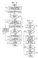
- Fig. 6 is a flow diagram illustrating the operation of a video encoder in accordance with the present invention;
- Fig. 7 shows a flow diagram illustrating the operation of a modified motion detector module in accordance with the present invention;
- Fig. 8 illustrates a flow diagram showing the operation of a modified motion compensation module in accordance with the present invention; and
- Fig. 9 is a block diagram depicting the operation of a zero block predictor module in accordance with the present invention.
- A video coder in accordance with the present invention, as shown in Fig. 3, includes several improvements to the video coder and video coding process of the prior art, shown in Fig. 1. The improvements shown in the video coder in accordance with the present invention as depicted in Fig. 3 provide for increased performance over video coders and video coding processes of the prior art. It is contemplated that the video coder and video coding process in accordance with the present invention are useful in any application using video coding techniques.
- The present invention is implemented in C++ using Microsoft's Visual C++ compiler on a workstation which included in a Pentium processor. It is contemplated, however, that use of other languages and hardware configurations would be apparent to those skilled in the art.
- The overall structure of the video coder in accordance with the present invention is shown in Fig. 3. As discussed hereinabove, the motion compensation stage and the transformation stage are among the most time consuming stages in a typical video coding process. The present invention provides for improvements to the motion detection stage as performed by modified
motion detector module 50. The modifiedmotion detector module 50 in accordance with the present invention determines whether to bypass the motion compensation stage performed by the modifiedmotion compensation module 52. The modifiedmotion compensation module 52 also includes improvements to the motion compensation stage over that of themotion compensation module 16 of the prior art. - The video coding process in accordance with the present invention also includes the addition of a zero block prediction stage, performed by zero
block predictor module 54. The zeroblock predictor module 54 determines whether or not to bypass the transformation and quantization stages. Each of these features are discussed in detail hereinbelow. - It is contemplated that other embodiments, in addition to that shown in Fig. 3, of the present invention are possible which also provide improvements to the video coder of the prior art. Another embodiment of the video coder in accordance with the present invention is shown in Fig. 4, which includes the modified
motion compensation module 52. Fig. 5 illustrates yet another embodiment of video coder in accordance with the present invention which includes the modifiedmotion detector module 50 and the zeroblock predictor module 54. - The operation of the video encoder shown in Fig. 3 is illustrated in Fig. 6. At
block 60, thecolor transformation module 12 generates data signals from the video image signals input at 51. - The data signals are then input to the modified
motion detector module 50 as shown atblock 62 which determines whether movement is detected in the represented image. If, atdecision block 64, movement is detected, the modifiedmotion compensation module 52, as shown atblock 66, compensates for that movement and operation continues atblock 68. If, atdecision block 64, movement is not detected, the motion compensation stage performed by the modifiedmotion compensation module 52 is bypassed and operation continues atblock 68. - At
block 68, the zeroblock predictor module 54 determines whether the currently processing macroblock of data signals will generate a zero-valued macroblock after the transformation and quantization stages performed by thetransform module 18 and thequantization module 20, respectively. If, atdecision block 70, a zero-valued macroblock is predicted, the transformation and quantization stages are bypassed and operation continues atblock 78. - If, at
decision block 70, a zero-valued macroblock is not predicted, operation continues at block 72 where the data signals are transformed by thetransform module 18. In the present invention, thetransform module 18 performs a discrete cosine transformation but, it is contemplated that other transformations may be used. The transformed data signals are then quantized atblock 74 by thequantization module 20. Atblock 76, the data signals of the currently processed image are used to generate an interpolated image which is fed back into the modifiedmotion compensation module 52 atblock 66. - The quantized data signals generated at
block 74 are encoded atblock 78 for further processing by the application which incorporates or uses the video coder of the present invention. - In the motion detection stage performed by the modified
motion detection module 50, the operation of which is illustrated in detail in Fig. 7, the macroblocks of the currently processing image processed are classified as either moving or stationary. In order to classify the macroblocks, the modifiedmotion detection module 50 determines if the macroblock has moved based upon predetermined motion criteria. The modifiedmotion detector module 50 then, using the predetermined motion criteria, compares the currently processing macroblock with a macroblock which is in the same location in the previous image, the interpolated image generated by thefeedback module 24, as the currently processing macroblock is in the current image. - The pixel-by-pixel absolute difference between the macroblock in the currently processing image and the macroblock at the same location in the previous image is calculated. If the difference between a pixel in the currently processing image and a pixel in the same location in the previous image is above a predetermined threshold, then that pixel is classified as moving within that macroblock. If the number of pixels classified as moving are above a second predetermined threshold, then the macroblock is classified as moving, otherwise the macroblock is classified as stationary. If the macroblock is stationary then the motion compensation phase is skipped entirely and computation proceeds as shown in Fig. 6.
- Returning to Fig. 7, if, at
decision block 110, the modifiedmotion detector module 50 is processing a macroblock in the first frame of data representing the current image (i.e., if it is an INTRA coded block), that macroblock is classified as stationary atblock 134 and processing by the modifiedmotion detector module 50 terminates. If, atdecision block 110, the current macroblock is not the first macroblock being processed, processing continues atblock 112 where a counter and a maximum data signal indicator are initialized. Operation then continues atblock 114 where the first pixel in the currently processing macroblock is retrieved. - If, at
decision block 116, the signal value of the current pixel in the currently processing macroblock is greater then the current value of the maximum data signal indicator, then the value of the maximum data signal indicator is replaced with the signal value atblock 118 and operation continues atblock 120. If, atdecision block 116, the signal value of the current pixel is not greater than the current value of the maximum data signal indicator then operation continues atblock 120 where the modifiedmotion detector module 50 determines the difference between the signal value of the current pixel and the signal value of the pixel in the same location in the previous image. - If, at
decision block 122, that difference is greater than the first predetermined threshold, the counter is incremented atblock 124 and operation continues atdecision block 126. If, atdecision block 122, the difference is not greater that the first predetermined threshold, operation also continues atdecision block 126 where, if there are more pixels in the currently processing macroblock, the next pixel is retrieved atblock 128 and operation continues atdecision block 116. If, atdecision block 126, all pixels in the current macroblock have been processed, a determination is made atdecision block 130 as to whether the counter is above the second predetermined threshold. - If, at
decision block 130, the counter is above the second predetermined threshold, the macroblock is classified as moving atblock 132. If, atdecision block 130, the counter is not above the second predetermined threshold, the macroblock is classified as stationary atblock 134. Operation in the modifiedmotion detector module 50 then terminates. - Returning to Fig. 6, if, as shown at
decision block 64, the modifiedmotion detector module 50 classifies the current macroblock as moving, the motion compensation stage performed by the modifiedmotion compensation module 52 is not bypassed. The modifiedmotion compensation module 52 operates as shown in Fig. 8. - The
motion compensation module 16 in video coders of the prior art and the modifiedmotion compensation module 52 in accordance with the present invention both uses a search procedure to find a best matching macroblock in the previous image then both perform a half-pel search around the best matching macroblock in an interpolated version of the represented image. If a full search block matching procedure is used, as in themotion compensation module 16 in video coders of the prior art, the motion compensation phase is an order of magnitude more expensive (in terms of adds and multiples) than any other phase of the video coding process. Therefore, to reduce the complexity of the motion compensation stage, the modifiedmotion compensation module 52 of the present invention includes several improvements. - As shown in
block 80 in Fig. 8, the modifiedmotion compensation module 80 first retrieves the macroblock from the previous image which is in the same location in the previous image as the currently processing macroblock is in the current image. The modifiedmotion compensation module 52 then determines, atblock 82, the sum of the absolute difference between the retrieved macroblock from the previous image and the currently processing macroblock in the current image. - If, at
decision block 84, the sum of absolute difference between the macroblock in the currently processing image and the macroblock at the same location in the previous image is below a certain predetermined threshold, then no further search is done and processing continues atblock 92 where the retrieved macroblock in the previous image is chosen as the best matching block. - If, at
decision block 84, the sum is above the predetermined threshold, processing continues atblock 86 where eight neighboring points around the center of the retrieved macroblock in the previous image are determined. the modifiedmotion compensation module 52 then determines, atblock 88, the sum of the absolute difference between the pixels in the currently processing macroblock and each macroblock in the previous image centered around one of the eight neighboring points. - This center biased orthogonal search algorithm (C-OSA) for block matching used by the
motion compensation module 52 of the present invention is an optimization of the orthogonal search algorithm (OSA) described in the article entitled "An Efficient Block-Matching Algorithm for Motion-Compensated Coding" by A. Puri, et al. and published in Proceeding IEEE ICASSSP 1987 on pages 25.4.1-25.4.4. The C-OSA used in the modifiedmotion compensation module 52 in the present invention performs a quick search on a set of eight neighboring points (+ or - one pixel in each direction and along the diagonals) centered around the search point in the retrieved macroblock in the previous image. - In the center-biased search procedure used in the modified
motion compensation module 52 of the present invention, if, atdecision block 90, the best-match occurs at the center, then no further search is done and processing continues atblock 92 where the macroblock centered around that best matching point is chosen. If, however, atdecision block 90, the best match occurs at one of the eight neighboring points, processing continues atdecision block 94. - If, at
decision block 94, the best match is at an orthogonal point ( a point which is + or - p pixel, where p is equal to 7, in any direction from the center point, i.e., not one of the points along a diagonal) then the searching procedure performed by the modifiedmotion compensation module 52 in the present invention proceeds as in the OSA procedure described in Puri, et al. If, however, atdecision block 94, the best match occurs instead at one of the eight neighboring points, then a new set of eight neighboring points is selected with that best matching point as the center point. The best match amongst this new set of eight neighboring points is returned atblock 100 as the result. Note that in the new set of eight neighboring points, not all eight points have to be recomputed since some were already computed previously. - It is worthwhile noting that the approach taken by the modified
motion compensation module 52 favors motion compensation on images where there is relatively little motion between successive images, which is typical of video conferencing applications. The C-OSA procedure used by the modifiedmotion compensation module 52 of the present invention includes a quick test to find the best matching block in a very small search area. In the worst case the modifiedmotion compensation module 52 of the present invention does a full orthogonal search which is still less complex and produces good results. The complexity of the C-OSA used in the modifiedmotion compensation module 52 of the present invention is 16+4log2w, where w is search distance in pixels, typically plus or minus 15 pixels. - Finally, as shown at
block 102, the modifiedmotion compensation module 52 of the present invention applies the OSA procedure described in Puri, et al. to the half-pel motion compensation search. The half-pel search is done on the interpolated image in a search area of plus or minus one pixel in all directions and along the diagonals. Surprisingly, this took more than a substantial proportion of the overall motion compensation time used by the modifiedmotion compensation module 52 since the full-pel search described hereinabove is already quite efficient. Applying the OSA procedure described in Puri, et al. on the half-pel search substantially reduced the number of search points. Also, the search area for border blocks is much smaller, since part of the area is not within the picture boundary, which provided additional savings in computation time. - Results obtained from the C-OSA and OSA procedures applied to full-pel and half-pel search, respectively, by the modified
motion compensation module 52 were very close to an exhaustive search with no noticeable degradation of image quality and resulted in an order of magnitude speed up of motion compensation when compared to the exhaustive search. On several ITU H.263 standard test images, including the "Miss America" image, motion compensation takes less than 12% of the total computing time with less than a .01 dB decrease in signal-to-noise ratio. - Returning to Fig. 6, on typical image sequences, e.g., on ITU test image sequences, less than 30% of INTER coded blocks had non-zero values after the quantization stage at 74 but all blocks had to go through the expensive transformation stage at block 72. Furthermore, the non-zero valued blocks had only one or two non-zero coefficients. To exploit the above observation a zero block prediction stage at 70 performed by the zero
block predictor module 54 is included after the motion compensation stage at 66. - The modified
motion detector module 50, as described in the hereinabove, classifies macroblocks as either moving or stationary. The modifiedmotion detector module 50 also records the maximum signal value and the number of stationary pixels in the entire macroblock. Based on a quantization value which changes as processing progresses, this information is used by the zeroblock predictor module 50 to determine or predict whether a macroblock will have all zero values after the transformation and quantization stages. If a zero-valued block is predicted, then the transformation and quantization stages, at 72 and 74, respectively, are skipped and a zero value block is generated. - The operation of the zero
block predictor module 54 is shown in Fig. 9. Atblock 140, the prediction is set to "no". If, atdecision block 142, a macroblock within the first frame is being processed, processing in the zeroblock predictor module 54 terminates. Otherwise, atblock 144, the zeroblock predictor module 54 applies heuristics using the maximum signal value, the number of stationary pixels, and the current quantization value to determine if the current macroblock will generate a zero-valued block after the transformation and quantization stages. If, atdecision block 146, a zero-valued block is predicted, then the prediction is set to "yes" atblock 148 and processing in the zeroblock predictor module 54 terminates. - The heuristics used by the zero
block predictor module 54 are only applied to INTER coded blocks. On average this saves about 30% of the blocks from going through the transformation and quantization stages. However, because of the conservative nature of the heuristic used by the zeroblock predictor module block predictor module 54 can be increased as the heuristics used are improved. - Before this optimization was applied, the transformation and quantization stages consumed about 30% of the total processing time. This reduced to about 18% after the above optimizations were applied. It is contemplated that the processing time can be further reduced if improved heuristics for predicting zero-valued blocks are applied. The overall video coding process in the present invention achieves about a 5-6 fold increase over the video coding process the ITU H.263 standard. Thus, the video coding process in accordance with the present invention is computationally more efficient and amenable to implementation using low-cost DSPs or software-only solutions.
- The techniques and concepts described in this invention were developed specifically for the video coding process used by video conferencing systems. However, it is contemplated that the present invention is also applicable to any application which uses video coding techniques for image compression.
- Although the present invention and its advantages have been described in detail, it should be understood that various changes, substitutions and alterations can be made herein without departing from the spirit and scope of the invention.
Claims (6)
- A video encoder comprising:a color transform module for receiving input video signals and for generating a first set of data signals representing a current image, including a plurality of pixels;a motion detector module coupled to said color transform module and responsive to said first set of data signals for generating a classification signal classifying said current image as moving or stationary;a motion compensation module responsive to said classification signal generated by said motion detector module and a second set of data signals representing a previous image generated by a feedback module for compensating for motion in said current image;a computational module responsive to said modified motion compensation module for generating digitized data signals from said first set of data signals;said feedback module responsive to said digitized data signals for generating said second set of data signals for input to said motion compensation module; anda coding module responsive to said digitized data signals for generating encoded data signals.
- The video encoder as claimed in Claim 1, wherein said motion compensation module is capable of applying a center-biased orthogonal search technique.
- The video encoder as claimed in Claim 1 or Claim 2, wherein said motion detector module is further responsive to a maximum value signal and a counter signal indicative of how many of said pixels are classified as stationary.
- The video encoder as claimed in Claim 3, further comprising: a zero block predictor module responsive to first set of data signals, said maximum value signal and said counter signal for generating a zero block signal indicative of whether computation on said first set of data signals will generate non-zero data; and
said computational module responsive to said zero block signal for generating said digitized data signals from said first set of data signals. - The system of any Claims 2 to 4, wherein said motion compensation module is operable to perform a full pel search in accordance with said center-biased orthogonal search technique.
- The system of any of Claims 2 to 4, wherein said motion compensation module is operable to perform a half pel search in accordance with an orthogonal search technique.
Priority Applications (1)
| Application Number | Priority Date | Filing Date | Title |
|---|---|---|---|
| EP97300452A EP0786907A3 (en) | 1997-01-24 | 1997-01-24 | Video encoder |
Applications Claiming Priority (1)
| Application Number | Priority Date | Filing Date | Title |
|---|---|---|---|
| EP97300452A EP0786907A3 (en) | 1997-01-24 | 1997-01-24 | Video encoder |
Publications (2)
| Publication Number | Publication Date |
|---|---|
| EP0786907A2 true EP0786907A2 (en) | 1997-07-30 |
| EP0786907A3 EP0786907A3 (en) | 2001-06-13 |
Family
ID=8229192
Family Applications (1)
| Application Number | Title | Priority Date | Filing Date |
|---|---|---|---|
| EP97300452A Withdrawn EP0786907A3 (en) | 1997-01-24 | 1997-01-24 | Video encoder |
Country Status (1)
| Country | Link |
|---|---|
| EP (1) | EP0786907A3 (en) |
Cited By (11)
| Publication number | Priority date | Publication date | Assignee | Title |
|---|---|---|---|---|
| WO1999034603A1 (en) * | 1997-12-31 | 1999-07-08 | Microsoft Corporation | Improved video coding using adaptive coding of block parameters for coded/uncoded blocks |
| WO2000008586A2 (en) * | 1998-08-07 | 2000-02-17 | Korea Institute Of Science And Technology | Apparatus and method for detecting a moving object in a sequence of color frame images |
| US6563953B2 (en) | 1998-11-30 | 2003-05-13 | Microsoft Corporation | Predictive image compression using a single variable length code for both the luminance and chrominance blocks for each macroblock |
| US7646810B2 (en) | 2002-01-25 | 2010-01-12 | Microsoft Corporation | Video coding |
| US7664177B2 (en) | 2003-09-07 | 2010-02-16 | Microsoft Corporation | Intra-coded fields for bi-directional frames |
| US8189666B2 (en) | 2009-02-02 | 2012-05-29 | Microsoft Corporation | Local picture identifier and computation of co-located information |
| US8254455B2 (en) | 2007-06-30 | 2012-08-28 | Microsoft Corporation | Computing collocated macroblock information for direct mode macroblocks |
| US8374245B2 (en) | 2002-06-03 | 2013-02-12 | Microsoft Corporation | Spatiotemporal prediction for bidirectionally predictive(B) pictures and motion vector prediction for multi-picture reference motion compensation |
| US8379722B2 (en) | 2002-07-19 | 2013-02-19 | Microsoft Corporation | Timestamp-independent motion vector prediction for predictive (P) and bidirectionally predictive (B) pictures |
| US9077960B2 (en) | 2005-08-12 | 2015-07-07 | Microsoft Corporation | Non-zero coefficient block pattern coding |
| US9774852B2 (en) | 2001-12-17 | 2017-09-26 | Microsoft Technology Licensing, Llc | Skip macroblock coding |
Families Citing this family (3)
| Publication number | Priority date | Publication date | Assignee | Title |
|---|---|---|---|---|
| US20050013498A1 (en) | 2003-07-18 | 2005-01-20 | Microsoft Corporation | Coding of motion vector information |
| US7724827B2 (en) | 2003-09-07 | 2010-05-25 | Microsoft Corporation | Multi-layer run level encoding and decoding |
| US7567617B2 (en) | 2003-09-07 | 2009-07-28 | Microsoft Corporation | Predicting motion vectors for fields of forward-predicted interlaced video frames |
Citations (2)
| Publication number | Priority date | Publication date | Assignee | Title |
|---|---|---|---|---|
| US5486863A (en) * | 1994-04-29 | 1996-01-23 | Motorola, Inc. | Method for determining whether to intra code a video block |
| US5590139A (en) * | 1993-03-01 | 1996-12-31 | Sony Corporation | Method of recording a compressed motion picture signal in which effects of rounding errors resulting from inversely transforming transaction coefficients representing are mitigated |
-
1997
- 1997-01-24 EP EP97300452A patent/EP0786907A3/en not_active Withdrawn
Patent Citations (2)
| Publication number | Priority date | Publication date | Assignee | Title |
|---|---|---|---|---|
| US5590139A (en) * | 1993-03-01 | 1996-12-31 | Sony Corporation | Method of recording a compressed motion picture signal in which effects of rounding errors resulting from inversely transforming transaction coefficients representing are mitigated |
| US5486863A (en) * | 1994-04-29 | 1996-01-23 | Motorola, Inc. | Method for determining whether to intra code a video block |
Non-Patent Citations (2)
| Title |
|---|
| LAI-MAN PO ET AL: "A new center-biased orthogonal search algorithm for fast block motion estimation", TENCON '96. PROCEEDINGS., 1996 IEEE TENCON. DIGITAL SIGNAL PROCESSING APPLICATIONS PERTH, WA, AUSTRALIA 26-29 NOV. 1996, NEW YORK, NY, USA,IEEE, US, vol. 2, 26 November 1996 (1996-11-26), pages 874-877, XP010236796, DOI: 10.1109/TENCON.1996.608462 ISBN: 978-0-7803-3679-7 * |
| XIAO FENG WANG ET AL: "IMAGE SEQUENCE CODING WITH HYBRID BLOCK OPERATION" PROCEEDINGS OF THE ASILOMAR CONFERENCE,US,NEW YORK, IEEE, 1 November 1993 (1993-11-01), pages 861-865, XP000438419 * |
Cited By (29)
| Publication number | Priority date | Publication date | Assignee | Title |
|---|---|---|---|---|
| WO1999034603A1 (en) * | 1997-12-31 | 1999-07-08 | Microsoft Corporation | Improved video coding using adaptive coding of block parameters for coded/uncoded blocks |
| WO2000008586A2 (en) * | 1998-08-07 | 2000-02-17 | Korea Institute Of Science And Technology | Apparatus and method for detecting a moving object in a sequence of color frame images |
| WO2000008586A3 (en) * | 1998-08-07 | 2001-09-20 | Korea Inst Sci & Tech | Apparatus and method for detecting a moving object in a sequence of color frame images |
| US6563953B2 (en) | 1998-11-30 | 2003-05-13 | Microsoft Corporation | Predictive image compression using a single variable length code for both the luminance and chrominance blocks for each macroblock |
| US6735345B2 (en) | 1998-11-30 | 2004-05-11 | Microsoft Corporation | Efficient macroblock header coding for video compression |
| US7054494B2 (en) | 1998-11-30 | 2006-05-30 | Microsoft Corporation | Coded block pattern decoding with spatial prediction |
| US7127114B2 (en) | 1998-11-30 | 2006-10-24 | Microsoft Corporation | Coded block pattern encoding with spatial prediction |
| US7289673B2 (en) | 1998-11-30 | 2007-10-30 | Microsoft Corporation | Decoding macroblock type and coded block pattern information |
| US10368065B2 (en) | 2001-12-17 | 2019-07-30 | Microsoft Technology Licensing, Llc | Skip macroblock coding |
| US9774852B2 (en) | 2001-12-17 | 2017-09-26 | Microsoft Technology Licensing, Llc | Skip macroblock coding |
| US8638853B2 (en) | 2002-01-25 | 2014-01-28 | Microsoft Corporation | Video coding |
| US8406300B2 (en) | 2002-01-25 | 2013-03-26 | Microsoft Corporation | Video coding |
| US9888237B2 (en) | 2002-01-25 | 2018-02-06 | Microsoft Technology Licensing, Llc | Video coding |
| US7646810B2 (en) | 2002-01-25 | 2010-01-12 | Microsoft Corporation | Video coding |
| US10284843B2 (en) | 2002-01-25 | 2019-05-07 | Microsoft Technology Licensing, Llc | Video coding |
| US8374245B2 (en) | 2002-06-03 | 2013-02-12 | Microsoft Corporation | Spatiotemporal prediction for bidirectionally predictive(B) pictures and motion vector prediction for multi-picture reference motion compensation |
| US10116959B2 (en) | 2002-06-03 | 2018-10-30 | Microsoft Technology Licesning, LLC | Spatiotemporal prediction for bidirectionally predictive (B) pictures and motion vector prediction for multi-picture reference motion compensation |
| US8873630B2 (en) | 2002-06-03 | 2014-10-28 | Microsoft Corporation | Spatiotemporal prediction for bidirectionally predictive (B) pictures and motion vector prediction for multi-picture reference motion compensation |
| US9185427B2 (en) | 2002-06-03 | 2015-11-10 | Microsoft Technology Licensing, Llc | Spatiotemporal prediction for bidirectionally predictive (B) pictures and motion vector prediction for multi-picture reference motion compensation |
| US9571854B2 (en) | 2002-06-03 | 2017-02-14 | Microsoft Technology Licensing, Llc | Spatiotemporal prediction for bidirectionally predictive (B) pictures and motion vector prediction for multi-picture reference motion compensation |
| US8379722B2 (en) | 2002-07-19 | 2013-02-19 | Microsoft Corporation | Timestamp-independent motion vector prediction for predictive (P) and bidirectionally predictive (B) pictures |
| US8774280B2 (en) | 2002-07-19 | 2014-07-08 | Microsoft Corporation | Timestamp-independent motion vector prediction for predictive (P) and bidirectionally predictive (B) pictures |
| US7852936B2 (en) | 2003-09-07 | 2010-12-14 | Microsoft Corporation | Motion vector prediction in bi-directionally predicted interlaced field-coded pictures |
| US7664177B2 (en) | 2003-09-07 | 2010-02-16 | Microsoft Corporation | Intra-coded fields for bi-directional frames |
| US7680185B2 (en) | 2003-09-07 | 2010-03-16 | Microsoft Corporation | Self-referencing bi-directionally predicted frames |
| US8064520B2 (en) | 2003-09-07 | 2011-11-22 | Microsoft Corporation | Advanced bi-directional predictive coding of interlaced video |
| US9077960B2 (en) | 2005-08-12 | 2015-07-07 | Microsoft Corporation | Non-zero coefficient block pattern coding |
| US8254455B2 (en) | 2007-06-30 | 2012-08-28 | Microsoft Corporation | Computing collocated macroblock information for direct mode macroblocks |
| US8189666B2 (en) | 2009-02-02 | 2012-05-29 | Microsoft Corporation | Local picture identifier and computation of co-located information |
Also Published As
| Publication number | Publication date |
|---|---|
| EP0786907A3 (en) | 2001-06-13 |
Similar Documents
| Publication | Publication Date | Title |
|---|---|---|
| US5886741A (en) | Method and apparatus for improved video coding using a zero block predictor module | |
| US5781249A (en) | Full or partial search block matching dependent on candidate vector prediction distortion | |
| US6980595B2 (en) | Method and system for distributed video compression in personal computer architecture | |
| EP1389016B1 (en) | Improved motion estimation and block matching pattern | |
| US5398068A (en) | Method and apparatus for determining motion vectors for image sequences | |
| US6483876B1 (en) | Methods and apparatus for reduction of prediction modes in motion estimation | |
| US4689671A (en) | Coding apparatus for moving object image | |
| EP0786907A2 (en) | Video encoder | |
| KR100251548B1 (en) | Apparatus of predicting motion for digital image and method thereof | |
| KR100242406B1 (en) | Method for motion estimation using trajectory in a digital video encoder | |
| JPH09191459A (en) | Method and device for coding video data flow of video sequence consisting of image block | |
| US6408101B1 (en) | Apparatus and method for employing M-ary pyramids to enhance feature-based classification and motion estimation | |
| US5689312A (en) | Block matching motion estimation method | |
| KR100286818B1 (en) | Fast motion estimating method for real-time video coding | |
| US20040013197A1 (en) | High-speed motion estimator and method with variable search window | |
| JP3418799B2 (en) | Motion vector correction control method | |
| JP4564599B2 (en) | Method and apparatus for improved video coding using a zero block predictor module | |
| KR0152014B1 (en) | Method and apparauts for moving estimation in image data compression | |
| Fadzil et al. | A hierarchical motion estimator for interframe coding | |
| KR100388802B1 (en) | apparatus and method for concealing error | |
| KR0174455B1 (en) | Method and apparatus for encoding a video signal using pixel-by-pixel motion prediction | |
| JPH07274182A (en) | Video signal encoding system | |
| GB2309135A (en) | Estimating image motion by comparing adjacent image frame signals | |
| JPH07123411A (en) | Movement vector sensing and transmitting methods | |
| KR100404328B1 (en) | Method for detecting motion vector of dynamic image |
Legal Events
| Date | Code | Title | Description |
|---|---|---|---|
| PUAI | Public reference made under article 153(3) epc to a published international application that has entered the european phase |
Free format text: ORIGINAL CODE: 0009012 |
|
| AK | Designated contracting states |
Kind code of ref document: A2 Designated state(s): DE FR GB IT NL |
|
| PUAL | Search report despatched |
Free format text: ORIGINAL CODE: 0009013 |
|
| AK | Designated contracting states |
Kind code of ref document: A3 Designated state(s): DE FR GB IT NL |
|
| RIC1 | Information provided on ipc code assigned before grant |
Free format text: 7H 04N 7/50 A, 7H 04N 7/26 B |
|
| 17P | Request for examination filed |
Effective date: 20011213 |
|
| AKX | Designation fees paid |
Free format text: DE FR GB IT NL |
|
| 17Q | First examination report despatched |
Effective date: 20071105 |
|
| GRAP | Despatch of communication of intention to grant a patent |
Free format text: ORIGINAL CODE: EPIDOSNIGR1 |
|
| RIC1 | Information provided on ipc code assigned before grant |
Ipc: H04N 19/00 20140101AFI20140428BHEP |
|
| INTG | Intention to grant announced |
Effective date: 20140602 |
|
| GRAS | Grant fee paid |
Free format text: ORIGINAL CODE: EPIDOSNIGR3 |
|
| STAA | Information on the status of an ep patent application or granted ep patent |
Free format text: STATUS: GRANT OF PATENT IS INTENDED |
|
| 18D | Application deemed to be withdrawn |
Effective date: 20141014 |