EP0786347A2 - A method for manufacturing a liquid jet recording head, a liquid jet recording head manufactured by such method, and a liquid jet recording apparatus having such head mounted thereon - Google Patents
A method for manufacturing a liquid jet recording head, a liquid jet recording head manufactured by such method, and a liquid jet recording apparatus having such head mounted thereon Download PDFInfo
- Publication number
- EP0786347A2 EP0786347A2 EP19960120829 EP96120829A EP0786347A2 EP 0786347 A2 EP0786347 A2 EP 0786347A2 EP 19960120829 EP19960120829 EP 19960120829 EP 96120829 A EP96120829 A EP 96120829A EP 0786347 A2 EP0786347 A2 EP 0786347A2
- Authority
- EP
- European Patent Office
- Prior art keywords
- jet recording
- liquid jet
- recording head
- cutting
- liquid
- Prior art date
- Legal status (The legal status is an assumption and is not a legal conclusion. Google has not performed a legal analysis and makes no representation as to the accuracy of the status listed.)
- Granted
Links
- 239000007788 liquid Substances 0.000 title claims abstract description 147
- 238000000034 method Methods 0.000 title claims abstract description 47
- 238000004519 manufacturing process Methods 0.000 title claims abstract description 34
- 238000005520 cutting process Methods 0.000 claims abstract description 118
- 238000003801 milling Methods 0.000 claims abstract description 26
- 230000015572 biosynthetic process Effects 0.000 claims abstract description 10
- 238000000227 grinding Methods 0.000 claims abstract description 7
- 238000010030 laminating Methods 0.000 claims abstract description 3
- 229910003460 diamond Inorganic materials 0.000 claims description 26
- 239000010432 diamond Substances 0.000 claims description 26
- 229910052782 aluminium Inorganic materials 0.000 claims description 22
- XAGFODPZIPBFFR-UHFFFAOYSA-N aluminium Chemical compound [Al] XAGFODPZIPBFFR-UHFFFAOYSA-N 0.000 claims description 22
- 239000011347 resin Substances 0.000 claims description 16
- 229920005989 resin Polymers 0.000 claims description 16
- 239000000463 material Substances 0.000 claims description 10
- 230000002463 transducing effect Effects 0.000 claims description 8
- 229920002492 poly(sulfone) Polymers 0.000 claims description 5
- RYGMFSIKBFXOCR-UHFFFAOYSA-N Copper Chemical compound [Cu] RYGMFSIKBFXOCR-UHFFFAOYSA-N 0.000 claims description 4
- 229910052802 copper Inorganic materials 0.000 claims description 4
- 239000010949 copper Substances 0.000 claims description 4
- 229910052751 metal Inorganic materials 0.000 claims description 4
- 239000002184 metal Substances 0.000 claims description 4
- 239000005011 phenolic resin Substances 0.000 claims description 4
- 239000004695 Polyether sulfone Substances 0.000 claims description 2
- 239000004697 Polyetherimide Substances 0.000 claims description 2
- 229920006393 polyether sulfone Polymers 0.000 claims description 2
- 229920001601 polyetherimide Polymers 0.000 claims description 2
- 229920000098 polyolefin Polymers 0.000 claims description 2
- 239000004734 Polyphenylene sulfide Substances 0.000 claims 1
- 229920000069 polyphenylene sulfide Polymers 0.000 claims 1
- 230000007547 defect Effects 0.000 abstract description 6
- VYPSYNLAJGMNEJ-UHFFFAOYSA-N Silicium dioxide Chemical compound O=[Si]=O VYPSYNLAJGMNEJ-UHFFFAOYSA-N 0.000 description 18
- 239000010408 film Substances 0.000 description 16
- 239000000758 substrate Substances 0.000 description 13
- 230000008901 benefit Effects 0.000 description 10
- 229910052681 coesite Inorganic materials 0.000 description 9
- 229910052906 cristobalite Inorganic materials 0.000 description 9
- 239000000377 silicon dioxide Substances 0.000 description 9
- 229910052682 stishovite Inorganic materials 0.000 description 9
- 229910052905 tridymite Inorganic materials 0.000 description 9
- 238000009413 insulation Methods 0.000 description 6
- 238000009835 boiling Methods 0.000 description 5
- 238000007599 discharging Methods 0.000 description 5
- 235000012431 wafers Nutrition 0.000 description 5
- 238000009825 accumulation Methods 0.000 description 4
- 239000003086 colorant Substances 0.000 description 4
- 239000000945 filler Substances 0.000 description 4
- 239000011521 glass Substances 0.000 description 4
- 230000008569 process Effects 0.000 description 4
- 239000004065 semiconductor Substances 0.000 description 4
- 229910052581 Si3N4 Inorganic materials 0.000 description 3
- 230000008859 change Effects 0.000 description 3
- 238000007796 conventional method Methods 0.000 description 3
- 230000003628 erosive effect Effects 0.000 description 3
- 238000001125 extrusion Methods 0.000 description 3
- 238000002347 injection Methods 0.000 description 3
- 239000007924 injection Substances 0.000 description 3
- 229910003465 moissanite Inorganic materials 0.000 description 3
- 238000000206 photolithography Methods 0.000 description 3
- 229920002120 photoresistant polymer Polymers 0.000 description 3
- 230000005855 radiation Effects 0.000 description 3
- 230000035939 shock Effects 0.000 description 3
- 229910010271 silicon carbide Inorganic materials 0.000 description 3
- PBCFLUZVCVVTBY-UHFFFAOYSA-N tantalum pentoxide Inorganic materials O=[Ta](=O)O[Ta](=O)=O PBCFLUZVCVVTBY-UHFFFAOYSA-N 0.000 description 3
- 238000012360 testing method Methods 0.000 description 3
- 229910001369 Brass Inorganic materials 0.000 description 2
- 239000011324 bead Substances 0.000 description 2
- 239000010951 brass Substances 0.000 description 2
- 238000004140 cleaning Methods 0.000 description 2
- 230000008602 contraction Effects 0.000 description 2
- 238000011161 development Methods 0.000 description 2
- 230000000694 effects Effects 0.000 description 2
- 238000010438 heat treatment Methods 0.000 description 2
- 238000009434 installation Methods 0.000 description 2
- 238000012423 maintenance Methods 0.000 description 2
- 239000007769 metal material Substances 0.000 description 2
- 239000007787 solid Substances 0.000 description 2
- 239000000243 solution Substances 0.000 description 2
- POFFJVRXOKDESI-UHFFFAOYSA-N 1,3,5,7-tetraoxa-4-silaspiro[3.3]heptane-2,6-dione Chemical compound O1C(=O)O[Si]21OC(=O)O2 POFFJVRXOKDESI-UHFFFAOYSA-N 0.000 description 1
- 229910000838 Al alloy Inorganic materials 0.000 description 1
- UCKMPCXJQFINFW-UHFFFAOYSA-N Sulphide Chemical compound [S-2] UCKMPCXJQFINFW-UHFFFAOYSA-N 0.000 description 1
- 230000002745 absorbent Effects 0.000 description 1
- 239000002250 absorbent Substances 0.000 description 1
- 239000000853 adhesive Substances 0.000 description 1
- 230000001070 adhesive effect Effects 0.000 description 1
- 230000002411 adverse Effects 0.000 description 1
- 230000005540 biological transmission Effects 0.000 description 1
- 239000011248 coating agent Substances 0.000 description 1
- 238000000576 coating method Methods 0.000 description 1
- 230000006835 compression Effects 0.000 description 1
- 238000007906 compression Methods 0.000 description 1
- 238000005336 cracking Methods 0.000 description 1
- 230000002349 favourable effect Effects 0.000 description 1
- 238000009499 grossing Methods 0.000 description 1
- 230000010365 information processing Effects 0.000 description 1
- 238000001746 injection moulding Methods 0.000 description 1
- 150000002739 metals Chemical class 0.000 description 1
- 238000002156 mixing Methods 0.000 description 1
- 230000003647 oxidation Effects 0.000 description 1
- 238000007254 oxidation reaction Methods 0.000 description 1
- 239000002245 particle Substances 0.000 description 1
- 230000002265 prevention Effects 0.000 description 1
- 238000011084 recovery Methods 0.000 description 1
- 230000004044 response Effects 0.000 description 1
- 230000000630 rising effect Effects 0.000 description 1
- 238000001179 sorption measurement Methods 0.000 description 1
- 230000003746 surface roughness Effects 0.000 description 1
- 238000007725 thermal activation Methods 0.000 description 1
- 239000010409 thin film Substances 0.000 description 1
Images


Classifications
-
- B—PERFORMING OPERATIONS; TRANSPORTING
- B41—PRINTING; LINING MACHINES; TYPEWRITERS; STAMPS
- B41J—TYPEWRITERS; SELECTIVE PRINTING MECHANISMS, i.e. MECHANISMS PRINTING OTHERWISE THAN FROM A FORME; CORRECTION OF TYPOGRAPHICAL ERRORS
- B41J2/00—Typewriters or selective printing mechanisms characterised by the printing or marking process for which they are designed
- B41J2/005—Typewriters or selective printing mechanisms characterised by the printing or marking process for which they are designed characterised by bringing liquid or particles selectively into contact with a printing material
- B41J2/01—Ink jet
- B41J2/135—Nozzles
- B41J2/16—Production of nozzles
- B41J2/1621—Manufacturing processes
- B41J2/164—Manufacturing processes thin film formation
- B41J2/1646—Manufacturing processes thin film formation thin film formation by sputtering
-
- B—PERFORMING OPERATIONS; TRANSPORTING
- B41—PRINTING; LINING MACHINES; TYPEWRITERS; STAMPS
- B41J—TYPEWRITERS; SELECTIVE PRINTING MECHANISMS, i.e. MECHANISMS PRINTING OTHERWISE THAN FROM A FORME; CORRECTION OF TYPOGRAPHICAL ERRORS
- B41J2/00—Typewriters or selective printing mechanisms characterised by the printing or marking process for which they are designed
- B41J2/005—Typewriters or selective printing mechanisms characterised by the printing or marking process for which they are designed characterised by bringing liquid or particles selectively into contact with a printing material
- B41J2/01—Ink jet
- B41J2/135—Nozzles
- B41J2/16—Production of nozzles
- B41J2/1601—Production of bubble jet print heads
- B41J2/1604—Production of bubble jet print heads of the edge shooter type
-
- B—PERFORMING OPERATIONS; TRANSPORTING
- B41—PRINTING; LINING MACHINES; TYPEWRITERS; STAMPS
- B41J—TYPEWRITERS; SELECTIVE PRINTING MECHANISMS, i.e. MECHANISMS PRINTING OTHERWISE THAN FROM A FORME; CORRECTION OF TYPOGRAPHICAL ERRORS
- B41J2/00—Typewriters or selective printing mechanisms characterised by the printing or marking process for which they are designed
- B41J2/005—Typewriters or selective printing mechanisms characterised by the printing or marking process for which they are designed characterised by bringing liquid or particles selectively into contact with a printing material
- B41J2/01—Ink jet
- B41J2/135—Nozzles
- B41J2/16—Production of nozzles
- B41J2/1621—Manufacturing processes
- B41J2/1631—Manufacturing processes photolithography
-
- B—PERFORMING OPERATIONS; TRANSPORTING
- B41—PRINTING; LINING MACHINES; TYPEWRITERS; STAMPS
- B41J—TYPEWRITERS; SELECTIVE PRINTING MECHANISMS, i.e. MECHANISMS PRINTING OTHERWISE THAN FROM A FORME; CORRECTION OF TYPOGRAPHICAL ERRORS
- B41J2/00—Typewriters or selective printing mechanisms characterised by the printing or marking process for which they are designed
- B41J2/005—Typewriters or selective printing mechanisms characterised by the printing or marking process for which they are designed characterised by bringing liquid or particles selectively into contact with a printing material
- B41J2/01—Ink jet
- B41J2/135—Nozzles
- B41J2/16—Production of nozzles
- B41J2/1621—Manufacturing processes
- B41J2/1632—Manufacturing processes machining
-
- B—PERFORMING OPERATIONS; TRANSPORTING
- B41—PRINTING; LINING MACHINES; TYPEWRITERS; STAMPS
- B41J—TYPEWRITERS; SELECTIVE PRINTING MECHANISMS, i.e. MECHANISMS PRINTING OTHERWISE THAN FROM A FORME; CORRECTION OF TYPOGRAPHICAL ERRORS
- B41J2/00—Typewriters or selective printing mechanisms characterised by the printing or marking process for which they are designed
- B41J2/005—Typewriters or selective printing mechanisms characterised by the printing or marking process for which they are designed characterised by bringing liquid or particles selectively into contact with a printing material
- B41J2/01—Ink jet
- B41J2/135—Nozzles
- B41J2/16—Production of nozzles
- B41J2/1621—Manufacturing processes
- B41J2/1635—Manufacturing processes dividing the wafer into individual chips
-
- B—PERFORMING OPERATIONS; TRANSPORTING
- B41—PRINTING; LINING MACHINES; TYPEWRITERS; STAMPS
- B41J—TYPEWRITERS; SELECTIVE PRINTING MECHANISMS, i.e. MECHANISMS PRINTING OTHERWISE THAN FROM A FORME; CORRECTION OF TYPOGRAPHICAL ERRORS
- B41J2/00—Typewriters or selective printing mechanisms characterised by the printing or marking process for which they are designed
- B41J2/005—Typewriters or selective printing mechanisms characterised by the printing or marking process for which they are designed characterised by bringing liquid or particles selectively into contact with a printing material
- B41J2/01—Ink jet
- B41J2/135—Nozzles
- B41J2/16—Production of nozzles
- B41J2/1621—Manufacturing processes
- B41J2/1637—Manufacturing processes molding
-
- Y—GENERAL TAGGING OF NEW TECHNOLOGICAL DEVELOPMENTS; GENERAL TAGGING OF CROSS-SECTIONAL TECHNOLOGIES SPANNING OVER SEVERAL SECTIONS OF THE IPC; TECHNICAL SUBJECTS COVERED BY FORMER USPC CROSS-REFERENCE ART COLLECTIONS [XRACs] AND DIGESTS
- Y10—TECHNICAL SUBJECTS COVERED BY FORMER USPC
- Y10T—TECHNICAL SUBJECTS COVERED BY FORMER US CLASSIFICATION
- Y10T29/00—Metal working
- Y10T29/49—Method of mechanical manufacture
- Y10T29/49401—Fluid pattern dispersing device making, e.g., ink jet
-
- Y—GENERAL TAGGING OF NEW TECHNOLOGICAL DEVELOPMENTS; GENERAL TAGGING OF CROSS-SECTIONAL TECHNOLOGIES SPANNING OVER SEVERAL SECTIONS OF THE IPC; TECHNICAL SUBJECTS COVERED BY FORMER USPC CROSS-REFERENCE ART COLLECTIONS [XRACs] AND DIGESTS
- Y10—TECHNICAL SUBJECTS COVERED BY FORMER USPC
- Y10T—TECHNICAL SUBJECTS COVERED BY FORMER US CLASSIFICATION
- Y10T407/00—Cutters, for shaping
- Y10T407/19—Rotary cutting tool
- Y10T407/1902—Gang
-
- Y—GENERAL TAGGING OF NEW TECHNOLOGICAL DEVELOPMENTS; GENERAL TAGGING OF CROSS-SECTIONAL TECHNOLOGIES SPANNING OVER SEVERAL SECTIONS OF THE IPC; TECHNICAL SUBJECTS COVERED BY FORMER USPC CROSS-REFERENCE ART COLLECTIONS [XRACs] AND DIGESTS
- Y10—TECHNICAL SUBJECTS COVERED BY FORMER USPC
- Y10T—TECHNICAL SUBJECTS COVERED BY FORMER US CLASSIFICATION
- Y10T407/00—Cutters, for shaping
- Y10T407/19—Rotary cutting tool
- Y10T407/1952—Having peripherally spaced teeth
- Y10T407/196—Varying in cutting edge profile
-
- Y—GENERAL TAGGING OF NEW TECHNOLOGICAL DEVELOPMENTS; GENERAL TAGGING OF CROSS-SECTIONAL TECHNOLOGIES SPANNING OVER SEVERAL SECTIONS OF THE IPC; TECHNICAL SUBJECTS COVERED BY FORMER USPC CROSS-REFERENCE ART COLLECTIONS [XRACs] AND DIGESTS
- Y10—TECHNICAL SUBJECTS COVERED BY FORMER USPC
- Y10T—TECHNICAL SUBJECTS COVERED BY FORMER US CLASSIFICATION
- Y10T83/00—Cutting
- Y10T83/02—Other than completely through work thickness
- Y10T83/0304—Grooving
Definitions
- the present invention relates to a liquid jet recording head used for a liquid jet recording apparatus of a bubble jet type or the like that discharges recording liquid (ink) from orifices (discharge ports) as droplets.
- the invention also relates to a method of manufacture for such head, and a liquid jet recording apparatus that mounts on it a liquid jet recording head manufactured by such method.
- a liquid jet recording apparatus of a bubble jet type or the like is powerful against external disturbances, and provides a good frequency of liquefaction. Therefore, it is made easier for the apparatus to perform a high-speed printing in good precision, and in colors, among others advantages. The future of this type of apparatus is greatly expected.
- a liquid jet recording head used for a liquid jet recording apparatus of the kind is provided with a base board 1001 having discharge energy generating elements, and a nozzle layer (liquid path formation layer) 1002 that forms liquid paths 1002b conductively connected to orifices (discharge ports) 1002a and a liquid chamber.
- the base board 1001 discharge energy generating elements 1011 by the known means of photo-lithography after an SiO 2 thermal oxidation film 1001a is provided for a monocrystal Si substrate.
- the surface thereof is covered by an electric insulation layer of SiO 2 , SiC, Si 3 N 4 , or the like, and also, by a protection layer 1001b formed by Ta film or the like for the prevention of damages (such as cavitation erosion) that may be caused to the discharge energy generating elements due to mechanical shock at the time of discharging recording liquid.
- a film of Ta 2 O 5 or the like is provided between the electric insulation layer and the Ta film in order to intensify the contact between them.
- a glass ceiling plate 1003 and others are arranged with an injection inlet to supply ink or other recording liquid.
- a liquid jet recording head of the kind is generally manufactured in the following steps of:
- a method is adapted as actual steps of the head manufacture that the nozzle layers are laminated for a portion of plural liquid jet recording heads on a base board having a large area, such as a six-inch or an eight-inch wafer as in the case of a semiconductor process, and then, the laminated body is cut off by use of a cutting blade into each individual liquid jet recording head, and that the cutting faces serving as each of the orifice surfaces are ground and polished for finishing.
- the nozzle layers are laminated on a large base board for a portion of plural liquid jet recording heads, and the laminated body thus obtained is cut off into each of the liquid jet recording heads.
- This cutting process is executed by use of the cutting blade adopted for a usual semiconductor process, which has a cutting width of several tens of ⁇ m to one mm. Therefore, as shown in Fig. 14, it is impossible to avoid creating a chipped portion V 1 on the base board 1001 with respect to the cutting face of the liquid jet recording head, which is an orifice surface, a chipped portion V 2 on the nozzle layer 1002, or a crack V 3 on the nozzle layer 1002.
- the chipped portion V 1 on the base board Compared with the chipped portion V 2 and the crack V 3 on the nozzle layer 1002, the chipped portion V 1 on the base board, in particular, tends to produce adverse effect on the shapes of the discharge ports 1002a and liquid paths 1002b on the nozzle layer 1002 to a considerable extent.
- the discharging direction of ink is caused to change conspicuously, thus resulting in the twisted prints and others defects, because the depth of the chipped portion V 1 of the base board 1001 may be as much as 10 ⁇ m or more.
- the basic material of the base board is an Si substrate, which is hard and brittle, and the heat accumulation layer, protection layer, and others provided on it are also formed mainly by SiO 2 , which is equally hard and brittle.
- the base board has properties as whole that it is extremely easy to be chipped off.
- the present invention is designed with a view to solving the problems encountered in the conventional techniques described above. It is an object of the invention to provide a high-performance but inexpensive liquid jet recording head having no defects such as chipped portions on the orifice surface to which the orifices (discharge ports) are open, and also, to provide a method of manufacture therefor, and a liquid jet recording apparatus having such liquid jet recording head mounted on it.
- an elongated head typically arranged by a head of a full-line type which corresponds to the maximum width of a recording medium such as a recording sheet
- a metallic base board is often used. This is due to the fact that the currently available configuration of wafers is only round that is used for the production of the Si substrate described above. Therefore, in a case of elongated heads, it is natural that the number of individual heads obtainable therefrom is extremely limited. Also, the costs of Si substrate is comparatively high.
- the metallic base board there are no problems as to the creation of chipped portions and cracking encountered when the Si base board is cut as described earlier. Therefore, the present inventor et al.
- the present invention is also designed in consideration of these technical problems yet to be solved in the conventional techniques. It is an object of the invention to provide a method for manufacturing a high-performance liquid jet recording bead whose production yield is high without having any defects such as chipped portions on the base board with respect to the orifice surface to which orifices (discharge ports) are open, and also, to provide a liquid jet recording head manufactured by such method of manufacture, and a liquid jet recording apparatus having on it a liquid jet head mounted thus manufactured.
- the method for manufacturing a liquid jet recording head of the present invention comprises the steps of obtaining a laminated body where liquid path formation layer is laminated to form liquid paths on a metallic base board having discharge energy generating means on it; forming the orifice surface by cutting the laminated body thus obtained; and grinding the orifice surface thus formed by means of a cutting tool or a milling cutter.
- the burrs created on the orifice surface of a metallic base board which has been cut off by use of a general blade or the like for cutting use, can be removed by use of a cutting tool whose tip is made of diamond or the like or a milling cutter arranged likewise for finishing and smoothing the orifice surface.
- a cutting tool whose tip is made of diamond or the like or a milling cutter arranged likewise for finishing and smoothing the orifice surface.
- the base board is formed by a metallic substrate, it can be produced at low costs as compared with the method whereby to adopt an Si substrate as a thin material as in the conventional art.
- the metallic substrate is better in heat radiation.
- Fig. 1 is a partly broken partial perspective view which shows the principal part of a liquid jet recording head in accordance with a first embodiment of the present invention.
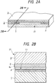
- Figs. 2A and 2B illustrate the steps of manufacture for the liquid jet recording head shown in Fig. 1.
- Fig. 2A is a partial perspective view showing the principal part of the liquid jet recording head in such steps of manufacture.
- Fig. 2B is a cross-sectional view taken along line 2B-2B in Fig. 2A.
- Fig. 3 is a partially enlarged view which shows a part of the orifice surface of the liquid jet recording head represented in Figs. 2A and 2B.
- Figs. 4A, 4B and 4C illustrate the step of finishing the liquid jet recording head represented in Figs. 2A and 2B.
- Fig. 4A is a cross-sectional view which schematically shows the liquid jet recording head in such finishing step and a diamond cutting tool.
- Figs. 4B and 4C are a plan view and a side view showing only the diamond cutting tool, respectively.
- Figs. 5A, 5B and 5C illustrate the step of finishing the liquid jet recording head using an end mill instead of the diamond cutting tool.
- Fig. 5A is a cross-sectional view which schematically shows the liquid jet recording head in such finishing step and the end mill.
- Figs. 5B and 5C are an elevational view and a side view showing only the end mill, respectively.
- Figs. 6A, 6B and 6C illustrate a side milling cutter and a method for manufacturing a liquid jet recording head in accordance with a second embodiment of the present invention.
- Fig. 6A is a view which illustrates the method for manufacturing a liquid jet recording head.
- Fig. 6B is an elevated sectional view which shows the side milling cutter.
- Fig. 6C is a view which illustrates the dimensional relationship between the cutting tool and the finishing tool shown in Fig. 6B.
- Fig. 7 is a view which shows a cut groove formed by the side milling cutter represented in Figs. 6A, 6B and 6C.
- Figs. 8A, 8B, 8C and 8D illustrate the cutting and finishing tools of the side milling cutter represented in Figs. 6A, 6B and 6C together with a shank.
- Figs. 8A and 8B are a side view and an elevational view showing the cutting tool and its shank, respectively.
- Figs. 8C and 8D are a side view and an elevational view showing the finishing tool and its shank, respectively.
- Figs. 9A and 9B show one variational example of the side milling cutter in accordance with the second embodiment of the present invention.
- Fig. 9A is the side view thereof.
- Fig. 9B is a view which illustrates each edge width of the tools.
- Fig. 10 is a view which shows a cut groove formed by the side milling cutter represented in Figs. 9A and 9B.
- Figs. 11A and 11B are views which illustrate two other variational examples, respectively.
- Fig. 12 is a view which schematically illustrates a liquid jet recording apparatus capable of mounting a liquid jet recording head of the present invention.
- Figs. 13A and 13B show liquid jet recording heads in accordance with the prior art.
- Fig. 13A is a perspective view which shows the principal part thereof.
- Fig. 13B is a cross-sectional view taken along line 13B-13B in Fig. 13A.
- Fig. 14 is a partially enlarged elevational view which shows a part of the orifice surface of the liquid jet recording head represented in Figs. 13A and 13B.
- Fig. 1 shows a liquid jet recording head of the first embodiment thereof, which comprises a base board 1 having discharge energy generating elements 11, and a nozzle layer (liquid path formation layer) 2 that forms liquid paths 2c conductively connected to orifices (discharge ports on the orifice surface) 21 and a liquid chamber 2c.
- the base board 1 is formed by an aluminum substrate serving as a metallic base board having a sputtered SiO 2 film provided on it as a heat accumulation layer, and then, by means of known photolithography the discharge energy generating elements 11 are formed.
- the surface thereof is covered by an electric insulation layer formed by SiO 2 , SiC, Si 3 N 4 , or the like, and a protection layer and others formed by a Ta film or the like to prevent any damages (such as cavitation erosion) from being caused to the discharge energy generating elements due to mechanical shocks when recording liquid is discharged. If needed, a Ta 2 O 5 film or the like is provided between the electric insulation layer and the Ta layer in order to intensify the contact between them. Also, there is arranged on the nozzle layer 2, an aluminum ceiling plate 3 and others serving as a second base board having an injection inlet 3a on it to supply ink or other recording liquid.
- This liquid jet recording head is manufactured in the following steps:
- a photoresist is coated on the base board 1 having the discharge energy generating elements 11 on it.
- the photoresist thus coated is exposed and developed to provide a resist pattern P having the inverted shape of the nozzle layer 2, and then, the aluminum ceiling plate 3 serving as the second base board is covered on it.
- a molten resin is injected into the space on the circumference of the resist pattern P, and it is hardened to obtain a laminated body.
- An orifice surface 21 is formed by cutting this body along the predetermined cutting face.
- the resist pattern P is eluded to cavitate each of the liquid paths 2b and the liquid chamber 2c on the nozzle layer 2 formed by resin as described earlier.
- a method is adapted in the actual steps of head manufacture that the nozzle layer for a portion of plural liquid jet recording heads is formed on a large area substrate such as a six-inch or eight-inch wafer as in the semiconductor process, and the laminated body thus obtained is cut off by use of a cutting blade into each of the liquid jet recording heads, and then, the orifice surface is ground and polished for finishing.
- an aluminum base board of 2 mm thick is used for the base board 1 instead of the Si base board that has been used for the conventional art.
- the heat accumulation layer is mainly formed by an SiO 2 film of 2.7 ⁇ m thick
- the protection layer is mainly formed by an SiO 2 film of 1.3 ⁇ m thick.
- the ceiling plate 3 is formed by aluminum instead of the glass that has been used for the conventional art.
- the base board 1 is formed by aluminum (a metallic base board), which is an extensible material, it has an advantage that chipped portions are not easily created as compared with the Si base board. Besides, it is inexpensive, while having a good heat radiation, and also, it presents an excellent smoothness, among other advantages. Therefore, using an aluminum base board it is possible to obtain a liquid jet recording head whose discharge performance is stabilized without any chipped portions on its orifice surface. Moreover, with a good heat radiation, it is possible to provide a higher discharge frequency, while obtaining a good adhesive coverage of a thin film pattern of 0.1 ⁇ m to several ⁇ m in the step of forming discharge energy generating elements, because the surface of the aluminum base board is smooth and flat. This contributes to the provision of another advantage that wiring is not easily broken.
- aluminum instead of aluminum, it may be possible to use copper, brass, or other metals for the metallic base board if only such metallic material has a good extensibility, and cut machinability as well.
- the metal bonded diamond edge conventionally in use is clogged heavily to make cutting impossible. Consequently, a resin bonded GC (silicon carbonate) blade is used.
- the cutting is executed by use of a resin bonded GC edge whose grain size is 320; diameter, 125 mm; thickness, 0.9 mm; at 4,600 rpm with a feeding speed of 180 mm/min.
- a burr B 1 is created in this stage as shown in Fig. 3 in a shape to close the orifice 2a.
- the burr B 1 is created equally in either cases.
- the resist pattern P is yet to be removed, but the burr B 1 in the lower part of the nozzle layer 2 is considerably large. It partly clogs the orifice 2a. Also, chips B 2 are caused on the nozzle layer 2. It is also found that an extrusion B 3 is created on the orifice surface 21 (see Fig. 2B and Fig. 4A).
- a finish cutting is executed by use of a diamond cutting tool T.
- the diamond cutting tool (JISB10107) T is provided with a diamond tip T 1 for use of the mirror finish of aluminum alloy or the like.
- a diamond-tipped milling cutter (JIS0172) or a cemented carbide cutting tool or milling cutter for the finishing cut.
- the finish cutting is executed in the condition given below.
- a diamond cutting tool T diamond curvature: 10 mm
- the cutting step is repeated five times each at 4,600 rpm, with a feeding speed of 46 mm/min, and for a biting amount of 10 ⁇ m.
- a liquid jet recording head thus produced is used for printing test with the result that excellent printing properties are obtained.
- a cemented carbide cutting tool is also used for finish cutting.
- the result of a test has shown the excellent printing properties.
- the diamond cutting tool should preferably be adopted, because using it the unwanted elements that may be created on the orifice surface are smaller.
- Figs. 5A, 5B and 5C are views which show such examples.
- a liquid jet recording head is manufactured by use of an end mill E having a diamond cutting tool R as shown in Fig. 5A for its finish cutting. Any other aspects than this use of end mill are the same as those described in the first embodiment.
- the end mill E With the end mill E, the roughness of the cutter edge is transferred to the orifice surface, because the feeding direction of the base board 1 is the same as the rotational direction of the cutter or it is opposite thereto. Therefore, instead of the usual diamond end mill that uses a sintered compact, the tip R 1 is formed by natural diamond for use as shown in Figs.
- the cutting condition is that an end mill of 10 mm diameter having its edge of 5 mm long is used at 15,000 rpm with the feeding speed of 150 mm/min for an amount of bite of 10 ⁇ m per cutting step. This step is repeated five times.
- this cutting setup results in a better orifice configuration above the ceiling plate as well as below the base board. Also, an advantage is obtainable that the extrusions remaining on the nozzle layer are smaller.
- each of the finishes obtained by use of the sintered diamond and cemented carbide end mills is examined, with the result that each of them indicates excellent printing properties.
- the materials of the base board and the ceiling plate it may be possible to use copper, brass, or some other metal that contains aluminum as its main component, besides aluminum itself, if only such metallic material has an excellent cut machinability.
- a liquid jet recording head is manufactured in the same manner as the first embodiment with the exception of the ceiling plate, which is formed by a phenol resin containing a filler, instead of aluminum. With a filler being contained in the phenol resin, the linear expansion coefficient thereof is made equal to that of aluminum.
- This ceiling plate has an advantage over the aluminum ceiling plate in that it is easier to be formed to incorporate an ink supplying system in it, and the liquid jet recording head can be manufactured at lower costs accordingly.
- the material of the ceiling plate it may be possible to use a polyetherimide containing a filler or pholyphenylene sulfide containing a filler, which provide a linear expansion coefficient closer to that of aluminum, besides the filler-contained phenol resin.
- a liquid jet recording head is manufactured in the same manner as the first embodiment with the exception of the ceiling plate, which is formed by polysulfone (PSF) instead of aluminum.
- the ceiling plate formed by a PSF of ultraviolet transmission type, it becomes possible to use a photohardening injection resin for the formation of a nozzle layer. In this way, a time required for hardening can be shortened significantly. Also, an advantage is obtainable that the inner condition of the nozzles can be observed, among others.
- the linear expansion coefficient becomes larger than that of aluminum, warping tends to occur during the heating process while manufacturing the liquid jet recording heads in this way.
- the shape of the ceiling plate is made more convex than that of the aluminum ceiling plate after cutting.
- polysulfone instead of the polysulfone, it may be possible to use a polyethersulfone of ultraviolet type or amorphous polyolefin for the ceiling plate.
- the cutting step of a liquid jet recording head, and the finishing step of the orifice surface are separately executed.
- the present embodiment presents a method for manufacturing a liquid jet recording head wherein the cutting step and the finishing step are executed at a time.
- the structural feature of the present embodiment is to adopt a side milling cutter for cutting the base board.
- the side milling cutter is provided with a rotational body, and also, with a plurality of cutting tips held in different positions in the circumferential direction of the rotational body, and also, with driving means to rotate this rotational body.
- one of the plural cutting tips is provided with a top cutting edge having a larger rotational radius than those of the tips of the other cutting edges.
- this side milling cutter serves as a cutting tool to form a cut groove on a work piece, while each of the remaining cutting tools are provided with the side cutting edge serving as finishing cutter to cut the side faces of the cut groove thus formed.
- these finishing cutters may be held on the rotational body stepwise in the width direction of each cutting edge, respectively.
- the width of cutting edge of the finishing cutter should preferably be larger in the circumferential direction of the rotational body as it is farther away from the one serving as the cutting tool.
- the present embodiment can contribute to simplifying the manufacturing steps of a liquid jet recording head, as well as to making the time of manufacturing cycle significantly shorter. Also, a cutting tool and finish tools are held on the same rotational body for revolution. As a result, it is possible to curtail the installation expenditures and maintenance costs to a considerable extent as compared with the separate use of cutting equipment for the cutting step and the finishing step, respectively.
- the cutting step and the finishing step are executed by each of different cutting tools, the cutting amount of each cutting tool is made smaller as compared with the case where the same cutting tool is applied both to cutting and finishing. Therefore, it becomes possible to enhance the precision remarkably when finishing the orifice surface by use of the cutting tool dedicated only to the finish operation.
- the width of each cutting edge can be made smaller as a whole. Consequently, there is an advantage that the width of cut groove can be made smaller accordingly, thus making it possible to obtain more numbers of liquid jet recording heads from one substrate.
- the liquid jet recording head comprises a base board 1 having discharge energy generating elements, and a nozzle layer (liquid path formation layer) 2 that forms liquid paths conductively connected to the discharge ports (orifices) 2a on an orifice surface 21, and a liquid chamber.
- the base board 1 is formed by an aluminum substrate serving as a metallic base board having a sputtered SiO 2 film provided on it as a heat accumulation layer, and then, by means of known photolithography the discharge energy generating elements are formed.
- the surface thereof is covered by an electric insulation layer formed by SiO 2 , SiC, Si 3 N 4 , or the like, and a protection layer and others formed by a Ta film or the like to prevent any damages (such as cavitation erosion) from being caused to the discharge energy generating elements due to mechanical shocks when recording liquid is discharged. If needed, a Ta 2 O 5 film or the like is provided between the electric insulation layer and the Ta layer in order to intensify the contact between them.
- a large area substrate 10 such as a six-inch or eight-inch wafer
- a nozzle layer 20 for a portion of plural liquid jet recording heads is laminated to produce a laminated body W.
- a side milling cutter 30 shown in Figs. 6B and 6C is used for the simultaneous execution of the cutting step to cut off each of the liquid jet recording heads and the finishing step to perform the surface finish of the orifice face 21 of each liquid jet recording head.
- the side milling cutter 30 is formed by holding a cutting tool 32 and a finishing tool 33 on the circumference of a circular flange 31 serving as a rotational body that rotates around the center of the rotational shaft O. Both of the tools are mounted outwardly on the same diameter in the diametral direction of the circular flange 31.
- Both the cutting tool 32 and finishing tool 33 are provided with trapezoidal cutting edges, respectively, and each of them is head on the flange 31 through each of shanks 34 and 35.
- the bottom width of the trapezoidal cutting edge of the cutting tool 32 that is, the edge width T 1
- the tip of the cutting tool 32 that is, the rotational radius R 1 of the top side (leading edge) 32a of the trapezoidal cutting tool is larger than the rotational radius R 2 of the top side 33a at the tip of the trapezoidal cutting edge of the finishing tool 33.
- the cutting edge of the cutting tool 32 executes the cutting operation to cut the laminated body W, that is, a work piece, into each of the liquid jet recording heads by use of the top side 32a and both sides 32b and 32c of the trapezoid thereof, and then, in continuation, the cutting edge of the finishing tool 33 executes finishing operation by use of only both sides (side edges) 33b and 33c to finish the orifice surface 21 of each of the liquid jet recording heads.
- Fig. 7 illustrates the shape of a cut groove S to be formed on the laminated body during the simultaneous steps of cutting and finishing by the revolution of the circular flange 31 as described above.
- the tip S 1 of the cut groove S is formed by use of the cutting tool 32, and the side face S 2 of the cut groove S is formed by use of the finishing tool 33.
- guide grooves 34a and 35a are provided for the shanks 34 and 35 of the cutting tool 32 and finishing tool 33.
- the mounting unit of the circular flange 31 is caused to move relatively to change the amounts of protrusions for the cutting tool 32 and finishing tool 33 in the respective diametral directions, hence adjusting the rotational radii R 1 and R 2 accordingly.
- the laminated body is cut off into each of the liquid jet recording heads, and then, the finishing step of each orifice surface is executed by the separate tool.
- the amount of cutting for each tool can be small, and there is no need for the use of a tool whose edge width is great as in the case of the same tool being used for the cutting and finishing steps at a time. Therefore, while there is no possibility that the number of liquid jet recording heads obtainable from one base board (wafer) is reduced, the finish of each orifice surface can be made in an extremely high precision.
- the cutting edge of the cutting tool can be either a sintered diamond or a cemented carbide, but it is desirable to use a natural diamond for the cutting edge of the finishing tool.
- Liquid jet recording heads are cut and finished by use of a natural diamond cutting tool having an edge width of 900 micron, and also, a natural diamond finishing tool having an edge width of 1,000 micron.
- the revolution N is set at 4,600 rpm with the feeding speed F of 120 mm/min.
- the tip of the finishing tool is not allowed to execute any cutting.
- the R 1 and R 2 are defined so that even when the revolution N and the feeding speed f change, the setup is always at (R 1 - R 2 ) > f. If the maximum feeding speed Fmax of an apparatus is 300/min, while the minimum revolution Nmin is 2,000 rpm, the maximum feeding amount fmax is 75 micron/tool. Therefore, it should be good enough if only the (R 1 - R 2 ) is adjusted to be 100 micron.
- each of the orifice surfaces of the liquid jet recording heads thus obtained as finished products is examined with the result: none of them present any burs, scratches, and chippings. The result of printing tests is also favorable.
- Fig. 9 shows one variational example of the side milling cutter.
- This cutter has three tools 42 to 44, each having different edge width, mounted on the circumference of a circular flange 41 at equal intervals.
- Each edge width of the tools 42 to 43 is varied stepwise in the circumferential direction of the circular flange 41 as shown in Fig. 9B.
- the tool 42 having the smallest edge width is to cut off a laminated body into liquid let recording heads.
- the remaining two tools 43 and 44 are to finish each of the orifice surfaces.
- the shape of a cut groove U formed on the laminated body V has two stages U 1 and U 2 at its top. Like this, a plurality of finishing tools may be arranged.
- tools 52 to 54 having the same edge width as shown in Fig. 11A, which are staged to be shifted in the direction of edge width, that is, in the axial direction of the circular flange when mounted thereon.
- a cut groove is formed by the tool 52, which is the forerunner, and only one side of the orifice surface of the cut groove is finished by the remaining two tools 53 and 54.
- tools 62 to 66 having the same edge width may be mounted on a circular flange in the direction of the edge width by shifting each of them alternately. With this arrangement, it is possible to tinish both sides of the orifice surface of the cut groove.
- reference numeral 101a to 101d designate each of line type liquid jet recording heads (hereinafter referred to as a head), respectively. These heads are fixedly supported in parallel to each other by a holder 102, which serves as a supporting member, at given intervals in the direction indicated by an arrow X. On the bottom end of each of the heads 101a to 101d, 3,456 discharge ports are arranged downward in one line at an interval of 16 discharge ports/mm in the direction indicated by arrows Y. With this arrangement, it is possible to record in a width of 216 mm.
- These heads 101a to 101d are of the type that discharges recording liquid by use of thermal energy. The discharge thereof is controlled by a head driver 120.
- a head unit is structured, which includes the heads 101a to 101d and the holder 102, and the head unit moves in the top and bottom directions by head moving means 124.
- each of the caps 103a to 103d arranged adjacently to the lower part of each of the heads 101a to 101d correspondingly is provided with an ink absorbent such as sponge in its interior, respectively.
- the caps 103a to 103d are fixedly supported by a holder (not shown). Then, a cap unit is structured, which includes the holder and caps 103a to 103d. The cap unit moves in the direction indicated by the arrow X by cap moving means 125.
- cyan, magenta, yellow, and black ink are supplied from ink tanks 104a to 104d through each of the ink supply tubes 105a to 105a, respectively, thus making color recording possible.
- the ink supply is made by utilization of capillary phenomenon created by the discharge ports of each head, and the liquid level of each of the ink tanks 104a to 104d is arranged lower by a specific distance than the position of discharge ports.
- a belt 106 is carrier means to carry a recording sheet 127, which serves as a recording material, and formed by a chargeable seamless belt.
- the belt 106 is drawn around a driving roller 107, idle rollers 109 and 109a, and a tension roller 110 by way of a given path, and then, connected to the driving roller 107.
- the belt runs by a belt driving motor driven by means of a motor driver 121.
- the belt 106 runs in the direction indicated by the arrow X directly underneath the discharge ports of the heads 101a to 101d. Here, its lower side deviation is suppressed by means of a fixedly supporting member 126.
- a cleaning unit 117 is arranged to remove paper particles and others adhering to the surface of the belt 106.
- An electrifier 112 that charges the belt 106 is turned on and off by means of an electrifier driver 122.
- the recording sheet 127 is adsorbed to the belt 106 by electrostatic adsorption when the belt is charged.
- pinch rollers 111 and 111a are arranged, which press a recording sheet 127 on the belt 106 to carry it in cooperation with the idler rollers 109 and 109a.
- Recording sheets 127 in a sheet feeding cassette 113 is fed out one by one by the rotation of a sheet feeding roller 116. Then, by means of the carrier roller 114 and the pinch roller 115, which are driven by the motor driver 123, the sheet is carried to an angled guide 113 in the direction indicated by the arrow X.
- the angled guide 113 has an angled space that allows the recording sheet 127 to bend.
- the recording sheet 127 is delivered to a tray 118 to receive delivered sheets.
- the head driver 120, head moving means 124, cap moving means 125, the motor drivers 121 and 123, and the electrifier driver 122 are all controlled by a controller 119.
- the present invention demonstrates particularly excellent effects when it is applied to a recording head and a recording apparatus of the so-called ink jet recording method that performs recording by forming flying droplets by utilization of thermal energy.
- discharge signals are supplied from a driving circuit to electrothermal transducing elements, which serve as discharge energy generating elements, disposed on a liquid (ink) retaining sheet or liquid path.
- at least one driving signal is given in order to provide recording liquid (ink) with a rapid temperature rise so that film boiling phenomenon, which is beyond nuclear boiling phenomenon, is created in the liquid, thus generating thermal energy to cause film boiling on the thermoactive surface of the recording head. Since an air bubble can be formed from the recording liquid (ink) by means of the driving signal given to an electrothermal transducing element one to one, this method is particularly effective for a recording method of on-demand type.
- the liquid (ink) is discharged through a discharge port to produce at least one droplet.
- the driving signal is more preferably in the form of pulses because the development and contraction of the bubble can be effectuated instantaneously and appropriately.
- the liquid (ink) is discharged with quicker response.
- the driving signal in the form of pulses is preferably such as disclosed in the specifications of U.S. Patent Nos. 4,463,359 and 4,345,262.
- the temperature increasing rate of the thermoactive surface is preferably such as disclosed in the specification of U.S. Patent No. 4,313,124 for an excellent recording in a better condition.
- the structure of the recording head may be as shown in each of the above-mentioned specifications wherein the structure is arranged to combine the discharging ports, liquid paths, and the electrothermal transducing elements (linear type liquid passages or right-angled liquid passages).
- the structure such as disclosed in the specifications of U.S. Patent Nos. 4,558,333 and 4,459,600 wherein the thermal activation portions are arranged in a curved area is also included in the present invention.
- the present invention is effectively applicable to the structure disclosed in Japanese Patent Laid-Open Application No. 59-123670 wherein a common slit is used as the discharging ports for plural electrothermal transducing elements, and to the structure disclosed in Japanese Patent Laid-Open Application No. 59-138461 wherein an aperture for absorbing pressure wave of the thermal energy is formed corresponding to the discharge ports.
- the present invention is effectively applicable to a recording head of full-line type having a length corresponding to the maximum width of a recording medium recordable by the recording apparatus.
- the full-line recording head it may be possible to adopt either a structure whereby to satisfy the required length by combining a plurality of recording heads or a structure arranged by one recording head integrally formed.
- the present invention is effectively applicable to an exchangeable recording head of a chip type that can be electrically connected with the apparatus main body, the ink supply therefor being made possible from the apparatus main body, when mounted on the apparatus main body or to the use of a cartridge type recording head provided integrally for the recording head itself.
- a recording head with recovery means and preliminarily auxiliary means because these additional means will contribute to making the effectiveness of a recording apparatus more stabilized.
- these additional means are capping means, cleaning means, suction or compression means, preheating means such as electrothermal transducing elements or heating elements other than such transducing elements or the combination of those types of elements, and a predischarge means for performing discharge other than the regular discharge with respect to the recording head.
- the present invention is not only applicable to a recording mode in which only one main color such as black is used for recording, but also, extremely effective in applying it to an apparatus having plural recording heads provided for use of at least one of multiple colors prepared by difference colors or a full-color prepared by mixing colors, irrespective of whether the recording heads are integrally structured or structured by a combination of plural recording heads.
- the most effective method applicable to various kinds of ink referred to in the preceding paragraph is the one that enables the film boiling method to be effectuated as described above.
- the mode of the recording apparatus of the present invention it may be possible to adopt a copying apparatus combined with a reader, in addition to the image output terminal for a computer or other information processing apparatus. Also, it may be possible to adopt a mode of a facsimile equipment provided with transmitting and receiving functions.
- the ink has been described as liquid, it may be an ink material which is solidified below the room temperature but soften or liquefied at the room temperature or soften or liquefied within a temperature range of the temperature adjustment, that is, not lower than 30°C but not higher than 70°C applicable to the general liquid jet recording.
- a temperature range of the temperature adjustment that is, not lower than 30°C but not higher than 70°C applicable to the general liquid jet recording.
- an ink having a nature of being liquefied only by the application of thermal energy such as an ink capable of being discharged as ink liquid by enabling itself to be liquefied anyway when the thermal energy is given in accordance with recording signals, and an ink which will have already begun solidifying itself by the time it reaches a recording medium.
- ink in the form of liquid or solid in the recesses or through holes of a porous sheet such as disclosed in Japanese Patent Laid-Open Application No. 54-56847 or 60-71260 in order to keep ink to be in the facing position with respect to the electrothermal transducing elements.
- the most effective method for the various kinds of ink mentioned above is the one that enables the film boiling method to be effectuated as described above.
- a method for manufacturing a liquid jet recording head comprises the steps of obtaining a laminated body by laminating a liquid path formation layer forming liquid paths on a metallic base board having discharge energy generating elements on it, forming an orifice surface by cutting the laminated body thus obtained, and grinding the orifice surface thus formed by use of a cutting tool or a milling cutter.
Abstract
Description
- The present invention relates to a liquid jet recording head used for a liquid jet recording apparatus of a bubble jet type or the like that discharges recording liquid (ink) from orifices (discharge ports) as droplets. The invention also relates to a method of manufacture for such head, and a liquid jet recording apparatus that mounts on it a liquid jet recording head manufactured by such method.
- A liquid jet recording apparatus of a bubble jet type or the like is powerful against external disturbances, and provides a good frequency of liquefaction. Therefore, it is made easier for the apparatus to perform a high-speed printing in good precision, and in colors, among others advantages. The future of this type of apparatus is greatly expected. As shown in Figs. 13A and 13B, a liquid jet recording head used for a liquid jet recording apparatus of the kind is provided with a
base board 1001 having discharge energy generating elements, and a nozzle layer (liquid path formation layer) 1002 that formsliquid paths 1002b conductively connected to orifices (discharge ports) 1002a and a liquid chamber. Generally, there are formed on thebase board 1001 dischargeenergy generating elements 1011 by the known means of photo-lithography after an SiO2thermal oxidation film 1001a is provided for a monocrystal Si substrate. The surface thereof is covered by an electric insulation layer of SiO2, SiC, Si3N4, or the like, and also, by aprotection layer 1001b formed by Ta film or the like for the prevention of damages (such as cavitation erosion) that may be caused to the discharge energy generating elements due to mechanical shock at the time of discharging recording liquid. Here, if necessary, a film of Ta2O5 or the like is provided between the electric insulation layer and the Ta film in order to intensify the contact between them. Also, on thenozzle layer 1002, aglass ceiling plate 1003 and others are arranged with an injection inlet to supply ink or other recording liquid. - A liquid jet recording head of the kind is generally manufactured in the following steps of:
- coating a photoresist on the base board having discharge energy generating elements on it;
- providing a resist pattern having an inverted shape of the nozzle layer by causing the board thus coated to be exposed and developed;
- covering the board thus prepared with the glass ceiling plate, and then, injecting molten resin into the space on the circumference of the resist pattern;
- hardening the resin and forming the orifice surface by cutting it along the predetermined cutting face; and lastly,
- eluding the resist pattern by use of a solution to cavitate each of the liquid paths on the nozzle layer.
- In place of the injection molding method described above, there is another method for forming the nozzle layer wherein a photohardening resin is coated on the base board having a resist pattern on it, and then, after the glass ceiling plate is installed on it, a beam is irradiated from above it to harden the resin. In this case, too, such steps are needed that after the resin is hardened, it is cut along the predetermined face, and that the resist pattern is eluded.
- In order to enhance the productivity of the liquid jet recording heads, a method is adapted as actual steps of the head manufacture that the nozzle layers are laminated for a portion of plural liquid jet recording heads on a base board having a large area, such as a six-inch or an eight-inch wafer as in the case of a semiconductor process, and then, the laminated body is cut off by use of a cutting blade into each individual liquid jet recording head, and that the cutting faces serving as each of the orifice surfaces are ground and polished for finishing.
- However, in accordance with the conventional techniques described above, the nozzle layers are laminated on a large base board for a portion of plural liquid jet recording heads, and the laminated body thus obtained is cut off into each of the liquid jet recording heads. This cutting process is executed by use of the cutting blade adopted for a usual semiconductor process, which has a cutting width of several tens of µm to one mm. Therefore, as shown in Fig. 14, it is impossible to avoid creating a chipped portion V1 on the
base board 1001 with respect to the cutting face of the liquid jet recording head, which is an orifice surface, a chipped portion V2 on thenozzle layer 1002, or a crack V3 on thenozzle layer 1002. - Compared with the chipped portion V2 and the crack V3 on the
nozzle layer 1002, the chipped portion V1 on the base board, in particular, tends to produce adverse effect on the shapes of the discharge ports 1002a andliquid paths 1002b on thenozzle layer 1002 to a considerable extent. For example, if an Si substrate of 0.5 mm or more in thickness is used for the basic material for thebase board 1001, the discharging direction of ink is caused to change conspicuously, thus resulting in the twisted prints and others defects, because the depth of the chipped portion V1 of thebase board 1001 may be as much as 10 µm or more. - This is due to the fact that the basic material of the base board is an Si substrate, which is hard and brittle, and the heat accumulation layer, protection layer, and others provided on it are also formed mainly by SiO2, which is equally hard and brittle. As a result, the base board has properties as whole that it is extremely easy to be chipped off.
- The present invention is designed with a view to solving the problems encountered in the conventional techniques described above. It is an object of the invention to provide a high-performance but inexpensive liquid jet recording head having no defects such as chipped portions on the orifice surface to which the orifices (discharge ports) are open, and also, to provide a method of manufacture therefor, and a liquid jet recording apparatus having such liquid jet recording head mounted on it.
- Meanwhile, among those liquid jet recording beads, an elongated head typically arranged by a head of a full-line type, which corresponds to the maximum width of a recording medium such as a recording sheet, a metallic base board is often used. This is due to the fact that the currently available configuration of wafers is only round that is used for the production of the Si substrate described above. Therefore, in a case of elongated heads, it is natural that the number of individual heads obtainable therefrom is extremely limited. Also, the costs of Si substrate is comparatively high. For the metallic base board, there are no problems as to the creation of chipped portions and cracking encountered when the Si base board is cut as described earlier. Therefore, the present inventor et al. have tried to produce liquid jet recording heads using metallic base boards in order to solve the problems described above. However, when using a metallic base board, the grinding jig used for grinding each orifice surface after cutting is often caused to be clogged. Thus, a problem is encountered anew that the production yield of liquid jet recording heads cannot be increased easily.
- The present invention is also designed in consideration of these technical problems yet to be solved in the conventional techniques. It is an object of the invention to provide a method for manufacturing a high-performance liquid jet recording bead whose production yield is high without having any defects such as chipped portions on the base board with respect to the orifice surface to which orifices (discharge ports) are open, and also, to provide a liquid jet recording head manufactured by such method of manufacture, and a liquid jet recording apparatus having on it a liquid jet head mounted thus manufactured.
- In order to achieve the objects described above, the method for manufacturing a liquid jet recording head of the present invention comprises the steps of obtaining a laminated body where liquid path formation layer is laminated to form liquid paths on a metallic base board having discharge energy generating means on it; forming the orifice surface by cutting the laminated body thus obtained; and grinding the orifice surface thus formed by means of a cutting tool or a milling cutter.
- In accordance with the present invention, the burrs created on the orifice surface of a metallic base board, which has been cut off by use of a general blade or the like for cutting use, can be removed by use of a cutting tool whose tip is made of diamond or the like or a milling cutter arranged likewise for finishing and smoothing the orifice surface. In this way, it is possible to obtain a high-performance liquid jet recording head whose discharging is stabilized with a smooth and perfect orifice surface.
- Further, since the base board is formed by a metallic substrate, it can be produced at low costs as compared with the method whereby to adopt an Si substrate as a thin material as in the conventional art. In addition to it, the metallic substrate is better in heat radiation. These advantages significantly contribute to providing a higher performance liquid jet recording head at lower costs.
- Fig. 1 is a partly broken partial perspective view which shows the principal part of a liquid jet recording head in accordance with a first embodiment of the present invention.
- Figs. 2A and 2B illustrate the steps of manufacture for the liquid jet recording head shown in Fig. 1. Fig. 2A is a partial perspective view showing the principal part of the liquid jet recording head in such steps of manufacture. Fig. 2B is a cross-sectional view taken along
line 2B-2B in Fig. 2A. - Fig. 3 is a partially enlarged view which shows a part of the orifice surface of the liquid jet recording head represented in Figs. 2A and 2B.
- Figs. 4A, 4B and 4C illustrate the step of finishing the liquid jet recording head represented in Figs. 2A and 2B. Fig. 4A is a cross-sectional view which schematically shows the liquid jet recording head in such finishing step and a diamond cutting tool. Figs. 4B and 4C are a plan view and a side view showing only the diamond cutting tool, respectively.
- Figs. 5A, 5B and 5C illustrate the step of finishing the liquid jet recording head using an end mill instead of the diamond cutting tool. Fig. 5A is a cross-sectional view which schematically shows the liquid jet recording head in such finishing step and the end mill. Figs. 5B and 5C are an elevational view and a side view showing only the end mill, respectively.
- Figs. 6A, 6B and 6C illustrate a side milling cutter and a method for manufacturing a liquid jet recording head in accordance with a second embodiment of the present invention. Fig. 6A is a view which illustrates the method for manufacturing a liquid jet recording head. Fig. 6B is an elevated sectional view which shows the side milling cutter. Fig. 6C is a view which illustrates the dimensional relationship between the cutting tool and the finishing tool shown in Fig. 6B.
- Fig. 7 is a view which shows a cut groove formed by the side milling cutter represented in Figs. 6A, 6B and 6C.
- Figs. 8A, 8B, 8C and 8D illustrate the cutting and finishing tools of the side milling cutter represented in Figs. 6A, 6B and 6C together with a shank. Figs. 8A and 8B are a side view and an elevational view showing the cutting tool and its shank, respectively. Figs. 8C and 8D are a side view and an elevational view showing the finishing tool and its shank, respectively.
- Figs. 9A and 9B show one variational example of the side milling cutter in accordance with the second embodiment of the present invention. Fig. 9A is the side view thereof. Fig. 9B is a view which illustrates each edge width of the tools.
- Fig. 10 is a view which shows a cut groove formed by the side milling cutter represented in Figs. 9A and 9B.
- Figs. 11A and 11B are views which illustrate two other variational examples, respectively.
- Fig. 12 is a view which schematically illustrates a liquid jet recording apparatus capable of mounting a liquid jet recording head of the present invention.
- Figs. 13A and 13B show liquid jet recording heads in accordance with the prior art. Fig. 13A is a perspective view which shows the principal part thereof. Fig. 13B is a cross-sectional view taken along
line 13B-13B in Fig. 13A. - Fig. 14 is a partially enlarged elevational view which shows a part of the orifice surface of the liquid jet recording head represented in Figs. 13A and 13B.
- Hereinafter, with reference to the accompanying drawings, the present invention will be described in detail.
- Now, in conjunction with Fig. 1, 2A, 2B, 3, 4A, 4B and 4C, a first embodiment will be described in accordance with the present invention.
- Fig. 1 shows a liquid jet recording head of the first embodiment thereof, which comprises a
base board 1 having dischargeenergy generating elements 11, and a nozzle layer (liquid path formation layer) 2 that formsliquid paths 2c conductively connected to orifices (discharge ports on the orifice surface) 21 and aliquid chamber 2c. Thebase board 1 is formed by an aluminum substrate serving as a metallic base board having a sputtered SiO2 film provided on it as a heat accumulation layer, and then, by means of known photolithography the dischargeenergy generating elements 11 are formed. The surface thereof is covered by an electric insulation layer formed by SiO2, SiC, Si3N4, or the like, and a protection layer and others formed by a Ta film or the like to prevent any damages (such as cavitation erosion) from being caused to the discharge energy generating elements due to mechanical shocks when recording liquid is discharged. If needed, a Ta2O5 film or the like is provided between the electric insulation layer and the Ta layer in order to intensify the contact between them. Also, there is arranged on thenozzle layer 2, analuminum ceiling plate 3 and others serving as a second base board having aninjection inlet 3a on it to supply ink or other recording liquid. - This liquid jet recording head is manufactured in the following steps:
- As shown in Figs. 2A and 2B, a photoresist is coated on the
base board 1 having the dischargeenergy generating elements 11 on it. The photoresist thus coated is exposed and developed to provide a resist pattern P having the inverted shape of thenozzle layer 2, and then, thealuminum ceiling plate 3 serving as the second base board is covered on it. A molten resin is injected into the space on the circumference of the resist pattern P, and it is hardened to obtain a laminated body. Anorifice surface 21 is formed by cutting this body along the predetermined cutting face. Lastly, by use of solution, the resist pattern P is eluded to cavitate each of theliquid paths 2b and theliquid chamber 2c on thenozzle layer 2 formed by resin as described earlier. - In place of a method of the kind, there is another method for forming a nozzle layer, in which a photo-hardening type resin is coated on a base board having a resist pattern on it, and after installing a transparent ceiling plate on it, a beam is irradiated from above the ceiling plate to harden the resin for the formation of the nozzle layer. In this case, too, there is a need for a step of cutting the hardened resin along the predetermined cutting face, and also for a step of eluding the resist pattern.
- In order to enhance the productivity of liquid jet recording heads, a method is adapted in the actual steps of head manufacture that the nozzle layer for a portion of plural liquid jet recording heads is formed on a large area substrate such as a six-inch or eight-inch wafer as in the semiconductor process, and the laminated body thus obtained is cut off by use of a cutting blade into each of the liquid jet recording heads, and then, the orifice surface is ground and polished for finishing.
- As described earlier, an aluminum base board of 2 mm thick is used for the
base board 1 instead of the Si base board that has been used for the conventional art. The heat accumulation layer is mainly formed by an SiO2 film of 2.7 µm thick, and the protection layer is mainly formed by an SiO2 film of 1.3 µm thick. Also, theceiling plate 3 is formed by aluminum instead of the glass that has been used for the conventional art. - Since the
base board 1 is formed by aluminum (a metallic base board), which is an extensible material, it has an advantage that chipped portions are not easily created as compared with the Si base board. Besides, it is inexpensive, while having a good heat radiation, and also, it presents an excellent smoothness, among other advantages. Therefore, using an aluminum base board it is possible to obtain a liquid jet recording head whose discharge performance is stabilized without any chipped portions on its orifice surface. Moreover, with a good heat radiation, it is possible to provide a higher discharge frequency, while obtaining a good adhesive coverage of a thin film pattern of 0.1 µm to several µm in the step of forming discharge energy generating elements, because the surface of the aluminum base board is smooth and flat. This contributes to the provision of another advantage that wiring is not easily broken. Here, instead of aluminum, it may be possible to use copper, brass, or other metals for the metallic base board if only such metallic material has a good extensibility, and cut machinability as well. - In the cutting step, it is found that the metal bonded diamond edge conventionally in use is clogged heavily to make cutting impossible. Consequently, a resin bonded GC (silicon carbonate) blade is used. In other words, the cutting is executed by use of a resin bonded GC edge whose grain size is 320; diameter, 125 mm; thickness, 0.9 mm; at 4,600 rpm with a feeding speed of 180 mm/min. On the cutting face (orifice surface) 21, a burr B1 is created in this stage as shown in Fig. 3 in a shape to close the
orifice 2a. - Although a resin bonded edge or a resin bonded diamond edge is usable for cutting, the burr B1 is created equally in either cases.
- The resist pattern P is yet to be removed, but the burr B1 in the lower part of the
nozzle layer 2 is considerably large. It partly clogs theorifice 2a. Also, chips B2 are caused on thenozzle layer 2. It is also found that an extrusion B3 is created on the orifice surface 21 (see Fig. 2B and Fig. 4A). - Therefore, as shown in Fig. 4A, a finish cutting is executed by use of a diamond cutting tool T. As shown in Figs. 4B (plan view) and 4C (side view), the diamond cutting tool (JISB10107) T is provided with a diamond tip T1 for use of the mirror finish of aluminum alloy or the like. Here, it may be possible to use a diamond-tipped milling cutter (JIS0172) or a cemented carbide cutting tool or milling cutter for the finishing cut.
- By the use of the diamond tip T1 for finish cutting as described above, it is possible to remove the burr B1 and the extrusion B3 created on the orifice surface in the cutting step.
- The finish cutting is executed in the condition given below. A diamond cutting tool T (diamond curvature: 10 mm) is mounted on a flange F having a diameter of 100 mm. The cutting step is repeated five times each at 4,600 rpm, with a feeding speed of 46 mm/min, and for a biting amount of 10 µm. A liquid jet recording head thus produced is used for printing test with the result that excellent printing properties are obtained.
- In place of the diamond cutting tool, a cemented carbide cutting tool is also used for finish cutting. In this case, too, the result of a test has shown the excellent printing properties. However, it is found that the diamond cutting tool should preferably be adopted, because using it the unwanted elements that may be created on the orifice surface are smaller.
- Now, the description will be made of one variational example of the first embodiment in accordance with the present invention.
- Figs. 5A, 5B and 5C are views which show such examples. In accordance with this example, a liquid jet recording head is manufactured by use of an end mill E having a diamond cutting tool R as shown in Fig. 5A for its finish cutting. Any other aspects than this use of end mill are the same as those described in the first embodiment. With the end mill E, the roughness of the cutter edge is transferred to the orifice surface, because the feeding direction of the
base board 1 is the same as the rotational direction of the cutter or it is opposite thereto. Therefore, instead of the usual diamond end mill that uses a sintered compact, the tip R1 is formed by natural diamond for use as shown in Figs. 5B and 5C, which are the elevated and side views thereof, respectively, in order to make the surface roughness of the orifice surface smaller. Here, the cutting condition is that an end mill of 10 mm diameter having its edge of 5 mm long is used at 15,000 rpm with the feeding speed of 150 mm/min for an amount of bite of 10 µm per cutting step. This step is repeated five times. - As compared with the use of a milling cutter, this cutting setup results in a better orifice configuration above the ceiling plate as well as below the base board. Also, an advantage is obtainable that the extrusions remaining on the nozzle layer are smaller. In this respect, each of the finishes obtained by use of the sintered diamond and cemented carbide end mills is examined, with the result that each of them indicates excellent printing properties. However, in consideration of the frequency in which defects are found on the orifice surface, it is preferable to use the sintered diamond to the cemented carbide, and the natural diamond to the sintered diamond.
- For the materials of the base board and the ceiling plate, it may be possible to use copper, brass, or some other metal that contains aluminum as its main component, besides aluminum itself, if only such metallic material has an excellent cut machinability.
- Now, as a second variational example of the first embodiment of the present invention, a liquid jet recording head is manufactured in the same manner as the first embodiment with the exception of the ceiling plate, which is formed by a phenol resin containing a filler, instead of aluminum. With a filler being contained in the phenol resin, the linear expansion coefficient thereof is made equal to that of aluminum. This ceiling plate has an advantage over the aluminum ceiling plate in that it is easier to be formed to incorporate an ink supplying system in it, and the liquid jet recording head can be manufactured at lower costs accordingly.
- Also, there is another advantage that both the cutting arid the finish cutting are easier to be executed than those required for the aluminum ceiling plate.
- As the material of the ceiling plate, it may be possible to use a polyetherimide containing a filler or pholyphenylene sulfide containing a filler, which provide a linear expansion coefficient closer to that of aluminum, besides the filler-contained phenol resin.
- Further, as a third variational example of the first embodiment of the present invention, a liquid jet recording head is manufactured in the same manner as the first embodiment with the exception of the ceiling plate, which is formed by polysulfone (PSF) instead of aluminum. With the ceiling plate formed by a PSF of ultraviolet transmission type, it becomes possible to use a photohardening injection resin for the formation of a nozzle layer. In this way, a time required for hardening can be shortened significantly. Also, an advantage is obtainable that the inner condition of the nozzles can be observed, among others. However, since the linear expansion coefficient becomes larger than that of aluminum, warping tends to occur during the heating process while manufacturing the liquid jet recording heads in this way. There is a need for a temperature control. Also, there is a tendency that the shape of the ceiling plate is made more convex than that of the aluminum ceiling plate after cutting.
- Instead of the polysulfone, it may be possible to use a polyethersulfone of ultraviolet type or amorphous polyolefin for the ceiling plate.
- In accordance with the first embodiment of the present invention, the cutting step of a liquid jet recording head, and the finishing step of the orifice surface are separately executed. However, the present embodiment presents a method for manufacturing a liquid jet recording head wherein the cutting step and the finishing step are executed at a time. The structural feature of the present embodiment is to adopt a side milling cutter for cutting the base board. Here, particularly, the side milling cutter is provided with a rotational body, and also, with a plurality of cutting tips held in different positions in the circumferential direction of the rotational body, and also, with driving means to rotate this rotational body. Here, one of the plural cutting tips is provided with a top cutting edge having a larger rotational radius than those of the tips of the other cutting edges. In this way, this side milling cutter serves as a cutting tool to form a cut groove on a work piece, while each of the remaining cutting tools are provided with the side cutting edge serving as finishing cutter to cut the side faces of the cut groove thus formed. In this respect, these finishing cutters may be held on the rotational body stepwise in the width direction of each cutting edge, respectively. Also, the width of cutting edge of the finishing cutter should preferably be larger in the circumferential direction of the rotational body as it is farther away from the one serving as the cutting tool.
- With the structure thus arranged, the present embodiment can contribute to simplifying the manufacturing steps of a liquid jet recording head, as well as to making the time of manufacturing cycle significantly shorter. Also, a cutting tool and finish tools are held on the same rotational body for revolution. As a result, it is possible to curtail the installation expenditures and maintenance costs to a considerable extent as compared with the separate use of cutting equipment for the cutting step and the finishing step, respectively.
- Moreover, since the cutting step and the finishing step are executed by each of different cutting tools, the cutting amount of each cutting tool is made smaller as compared with the case where the same cutting tool is applied both to cutting and finishing. Therefore, it becomes possible to enhance the precision remarkably when finishing the orifice surface by use of the cutting tool dedicated only to the finish operation.
- Further, since the cutting amount is smaller for each of the cutting tools, the width of each cutting edge can be made smaller as a whole. Consequently, there is an advantage that the width of cut groove can be made smaller accordingly, thus making it possible to obtain more numbers of liquid jet recording heads from one substrate.
- Now, with reference to the accompanying drawings, the description will be made of the second embodiment in accordance with the present invention.
- Figs. 6A, 6B and 6C illustrate a side milling cutter and a method for manufacturing a liquid jet recording head in accordance with the present embodiment. As a finished product, the liquid jet recording head comprises a
base board 1 having discharge energy generating elements, and a nozzle layer (liquid path formation layer) 2 that forms liquid paths conductively connected to the discharge ports (orifices) 2a on anorifice surface 21, and a liquid chamber. Thebase board 1 is formed by an aluminum substrate serving as a metallic base board having a sputtered SiO2 film provided on it as a heat accumulation layer, and then, by means of known photolithography the discharge energy generating elements are formed. The surface thereof is covered by an electric insulation layer formed by SiO2, SiC, Si3N4, or the like, and a protection layer and others formed by a Ta film or the like to prevent any damages (such as cavitation erosion) from being caused to the discharge energy generating elements due to mechanical shocks when recording liquid is discharged. If needed, a Ta2O5 film or the like is provided between the electric insulation layer and the Ta layer in order to intensify the contact between them. - At first, in the same manner known as semiconductor process, a
large area substrate 10, such as a six-inch or eight-inch wafer, anozzle layer 20 for a portion of plural liquid jet recording heads is laminated to produce a laminated body W. By cutting the laminated body W along cutting lines M, each of the liquid jet recording heads is cut off. Here, aside milling cutter 30 shown in Figs. 6B and 6C is used for the simultaneous execution of the cutting step to cut off each of the liquid jet recording heads and the finishing step to perform the surface finish of theorifice face 21 of each liquid jet recording head. - The
side milling cutter 30 is formed by holding acutting tool 32 and afinishing tool 33 on the circumference of acircular flange 31 serving as a rotational body that rotates around the center of the rotational shaft O. Both of the tools are mounted outwardly on the same diameter in the diametral direction of thecircular flange 31. - Both the
cutting tool 32 and finishingtool 33 are provided with trapezoidal cutting edges, respectively, and each of them is head on theflange 31 through each ofshanks cutting tool 32, that is, the edge width T1, is smaller than the edge width T2 of the finishingtool 33. Also, the tip of thecutting tool 32, that is, the rotational radius R1 of the top side (leading edge) 32a of the trapezoidal cutting tool is larger than the rotational radius R2 of thetop side 33a at the tip of the trapezoidal cutting edge of the finishingtool 33. - When the
circular flange 31 rotates by use of driving means (not shown), the cutting edge of thecutting tool 32 executes the cutting operation to cut the laminated body W, that is, a work piece, into each of the liquid jet recording heads by use of thetop side 32a and bothsides tool 33 executes finishing operation by use of only both sides (side edges) 33b and 33c to finish theorifice surface 21 of each of the liquid jet recording heads. - Fig. 7 illustrates the shape of a cut groove S to be formed on the laminated body during the simultaneous steps of cutting and finishing by the revolution of the
circular flange 31 as described above. The tip S1 of the cut groove S is formed by use of thecutting tool 32, and the side face S2 of the cut groove S is formed by use of the finishingtool 33. - In order not to allow the
tip 33a of the finishingtool 33 to cut the top end S1 of the cut groove S formed by the cuttingtool 32, it is necessary to satisfy the following relationships between the revolution of thecircular flange 31, that is, the revolution N of the side milling cutter and the feeding speed F, and the rotational radii R1 and R2 of the finishing tool 33:
circular flange 31. - Here, as shown in Figs. 8A to 8D, guide
grooves shanks cutting tool 32 and finishingtool 33. Along these guide grooves, the mounting unit of thecircular flange 31 is caused to move relatively to change the amounts of protrusions for thecutting tool 32 and finishingtool 33 in the respective diametral directions, hence adjusting the rotational radii R1 and R2 accordingly. - In accordance with the present embodiment, the laminated body is cut off into each of the liquid jet recording heads, and then, the finishing step of each orifice surface is executed by the separate tool. As a result, the amount of cutting for each tool can be small, and there is no need for the use of a tool whose edge width is great as in the case of the same tool being used for the cutting and finishing steps at a time. Therefore, while there is no possibility that the number of liquid jet recording heads obtainable from one base board (wafer) is reduced, the finish of each orifice surface can be made in an extremely high precision. Also, with the cutting and finishing tools being mounted on one and the same circular flange for revolution, there is no possibility that the steps of manufacturing liquid jet recording heads become complicated, and that the installation expenditures and maintenance costs become higher unlike the case where each of the cutting and finishing tools should be rotated individually.
- As a result, the manufacturing costs of liquid jet recording heads are significantly reduced.
- In this respect, the cutting edge of the cutting tool can be either a sintered diamond or a cemented carbide, but it is desirable to use a natural diamond for the cutting edge of the finishing tool.
- Now, a specific example will be described.
- Liquid jet recording heads are cut and finished by use of a natural diamond cutting tool having an edge width of 900 micron, and also, a natural diamond finishing tool having an edge width of 1,000 micron.
- The revolution N is set at 4,600 rpm with the feeding speed F of 120 mm/min.
- Now that the number n of tools is 2, the feeding speed f per tool is:

- Here, it is important that the R1 and R2 are defined so that even when the revolution N and the feeding speed f change, the setup is always at (R1 - R2) > f. If the maximum feeding speed Fmax of an apparatus is 300/min, while the minimum revolution Nmin is 2,000 rpm, the maximum feeding amount fmax is 75 micron/tool. Therefore, it should be good enough if only the (R1 - R2) is adjusted to be 100 micron. Here, each of the orifice surfaces of the liquid jet recording heads thus obtained as finished products is examined with the result: none of them present any burs, scratches, and chippings. The result of printing tests is also favorable.
- Fig. 9 shows one variational example of the side milling cutter. This cutter has three
tools 42 to 44, each having different edge width, mounted on the circumference of acircular flange 41 at equal intervals. Each edge width of thetools 42 to 43 is varied stepwise in the circumferential direction of thecircular flange 41 as shown in Fig. 9B. Thetool 42 having the smallest edge width is to cut off a laminated body into liquid let recording heads. The remaining twotools tools 52 to 54 having the same edge width as shown in Fig. 11A, which are staged to be shifted in the direction of edge width, that is, in the axial direction of the circular flange when mounted thereon. - In this case, a cut groove is formed by the
tool 52, which is the forerunner, and only one side of the orifice surface of the cut groove is finished by the remaining twotools tools 62 to 66 having the same edge width may be mounted on a circular flange in the direction of the edge width by shifting each of them alternately. With this arrangement, it is possible to tinish both sides of the orifice surface of the cut groove. - Now, with reference to Fig. 12, the description will be made of a liquid jet recording apparatus to which a liquid jet recording head of the present invention is applicable.
- In Fig. 12,
reference numeral 101a to 101d designate each of line type liquid jet recording heads (hereinafter referred to as a head), respectively. These heads are fixedly supported in parallel to each other by aholder 102, which serves as a supporting member, at given intervals in the direction indicated by an arrow X. On the bottom end of each of theheads 101a to 101d, 3,456 discharge ports are arranged downward in one line at an interval of 16 discharge ports/mm in the direction indicated by arrows Y. With this arrangement, it is possible to record in a width of 216 mm. - These
heads 101a to 101d are of the type that discharges recording liquid by use of thermal energy. The discharge thereof is controlled by ahead driver 120. - In this respect, a head unit is structured, which includes the
heads 101a to 101d and theholder 102, and the head unit moves in the top and bottom directions by head moving means 124. - Also, each of the
caps 103a to 103d arranged adjacently to the lower part of each of theheads 101a to 101d correspondingly is provided with an ink absorbent such as sponge in its interior, respectively. - The
caps 103a to 103d are fixedly supported by a holder (not shown). Then, a cap unit is structured, which includes the holder andcaps 103a to 103d. The cap unit moves in the direction indicated by the arrow X bycap moving means 125. - To each of the
heads 101a to 101d, cyan, magenta, yellow, and black ink are supplied fromink tanks 104a to 104d through each of theink supply tubes 105a to 105a, respectively, thus making color recording possible. - Also, the ink supply is made by utilization of capillary phenomenon created by the discharge ports of each head, and the liquid level of each of the
ink tanks 104a to 104d is arranged lower by a specific distance than the position of discharge ports. - A
belt 106 is carrier means to carry arecording sheet 127, which serves as a recording material, and formed by a chargeable seamless belt. - The
belt 106 is drawn around a drivingroller 107,idle rollers tension roller 110 by way of a given path, and then, connected to the drivingroller 107. The belt runs by a belt driving motor driven by means of amotor driver 121. - Also, the
belt 106 runs in the direction indicated by the arrow X directly underneath the discharge ports of theheads 101a to 101d. Here, its lower side deviation is suppressed by means of a fixedly supportingmember 126. - On the lower part where the
belt 106 shown in Fig. 12, acleaning unit 117 is arranged to remove paper particles and others adhering to the surface of thebelt 106. - An
electrifier 112 that charges thebelt 106 is turned on and off by means of anelectrifier driver 122. Therecording sheet 127 is adsorbed to thebelt 106 by electrostatic adsorption when the belt is charged. - In the front and rear of the
electrifier 112,pinch rollers recording sheet 127 on thebelt 106 to carry it in cooperation with theidler rollers - Recording
sheets 127 in asheet feeding cassette 113 is fed out one by one by the rotation of asheet feeding roller 116. Then, by means of thecarrier roller 114 and thepinch roller 115, which are driven by themotor driver 123, the sheet is carried to anangled guide 113 in the direction indicated by the arrow X. Theangled guide 113 has an angled space that allows therecording sheet 127 to bend. - After recording, the
recording sheet 127 is delivered to atray 118 to receive delivered sheets. - The
head driver 120, head moving means 124, cap moving means 125, themotor drivers electrifier driver 122 are all controlled by acontroller 119. - Of the liquid jet recording methods, the present invention demonstrates particularly excellent effects when it is applied to a recording head and a recording apparatus of the so-called ink jet recording method that performs recording by forming flying droplets by utilization of thermal energy.
- Regarding the typical structure and operational principle of such method, it is preferable for the present invention to adopt those which can be implemented using the fundamental principle disclosed in the specifications of U.S. Patent Nos 4,723,129 and 4,740,796, for example. This method is applicable to the so-called on-demand type recording system and a continuous type recording system as well.
- To briefly describe this recording method, discharge signals are supplied from a driving circuit to electrothermal transducing elements, which serve as discharge energy generating elements, disposed on a liquid (ink) retaining sheet or liquid path. In other words, in accordance with recording information, at least one driving signal is given in order to provide recording liquid (ink) with a rapid temperature rise so that film boiling phenomenon, which is beyond nuclear boiling phenomenon, is created in the liquid, thus generating thermal energy to cause film boiling on the thermoactive surface of the recording head. Since an air bubble can be formed from the recording liquid (ink) by means of the driving signal given to an electrothermal transducing element one to one, this method is particularly effective for a recording method of on-demand type. By the development and contraction of the bubble, the liquid (ink) is discharged through a discharge port to produce at least one droplet. The driving signal is more preferably in the form of pulses because the development and contraction of the bubble can be effectuated instantaneously and appropriately. The liquid (ink) is discharged with quicker response. The driving signal in the form of pulses is preferably such as disclosed in the specifications of U.S. Patent Nos. 4,463,359 and 4,345,262. In this respect, the temperature increasing rate of the thermoactive surface is preferably such as disclosed in the specification of U.S. Patent No. 4,313,124 for an excellent recording in a better condition.
- The structure of the recording head may be as shown in each of the above-mentioned specifications wherein the structure is arranged to combine the discharging ports, liquid paths, and the electrothermal transducing elements (linear type liquid passages or right-angled liquid passages). Besides, the structure such as disclosed in the specifications of U.S. Patent Nos. 4,558,333 and 4,459,600 wherein the thermal activation portions are arranged in a curved area is also included in the present invention.
- Furthermore, the present invention is effectively applicable to the structure disclosed in Japanese Patent Laid-Open Application No. 59-123670 wherein a common slit is used as the discharging ports for plural electrothermal transducing elements, and to the structure disclosed in Japanese Patent Laid-Open Application No. 59-138461 wherein an aperture for absorbing pressure wave of the thermal energy is formed corresponding to the discharge ports.
- Further, the present invention is effectively applicable to a recording head of full-line type having a length corresponding to the maximum width of a recording medium recordable by the recording apparatus. For the full-line recording head, it may be possible to adopt either a structure whereby to satisfy the required length by combining a plurality of recording heads or a structure arranged by one recording head integrally formed.
- In addition, the present invention is effectively applicable to an exchangeable recording head of a chip type that can be electrically connected with the apparatus main body, the ink supply therefor being made possible from the apparatus main body, when mounted on the apparatus main body or to the use of a cartridge type recording head provided integrally for the recording head itself.
- Also, it is preferable to additionally provide a recording head with recovery means and preliminarily auxiliary means because these additional means will contribute to making the effectiveness of a recording apparatus more stabilized. To name them specifically, these are capping means, cleaning means, suction or compression means, preheating means such as electrothermal transducing elements or heating elements other than such transducing elements or the combination of those types of elements, and a predischarge means for performing discharge other than the regular discharge with respect to the recording head.
- Also, as the recording modes of a recording apparatus, the present invention is not only applicable to a recording mode in which only one main color such as black is used for recording, but also, extremely effective in applying it to an apparatus having plural recording heads provided for use of at least one of multiple colors prepared by difference colors or a full-color prepared by mixing colors, irrespective of whether the recording heads are integrally structured or structured by a combination of plural recording heads.
- For the present invention, the most effective method applicable to various kinds of ink referred to in the preceding paragraph is the one that enables the film boiling method to be effectuated as described above.
- Furthermore, as the mode of the recording apparatus of the present invention, it may be possible to adopt a copying apparatus combined with a reader, in addition to the image output terminal for a computer or other information processing apparatus. Also, it may be possible to adopt a mode of a facsimile equipment provided with transmitting and receiving functions.
- In the embodiments of the present invention described above, while the ink has been described as liquid, it may be an ink material which is solidified below the room temperature but soften or liquefied at the room temperature or soften or liquefied within a temperature range of the temperature adjustment, that is, not lower than 30°C but not higher than 70°C applicable to the general liquid jet recording. In other words, if only ink is liquefied at the time of giving recording signals for use, any one of them should be good enough for use. In addition, while positively preventing the temperature from rising due to thermal energy by the use of such energy as an energy to be consumed far changing states of ink from solid to liquid, or by the use of the ink which will be solidified when left intact for the purpose of preventing the ink from being evaporated, it may be possible to adopt for the present invention the use of an ink having a nature of being liquefied only by the application of thermal energy, such as an ink capable of being discharged as ink liquid by enabling itself to be liquefied anyway when the thermal energy is given in accordance with recording signals, and an ink which will have already begun solidifying itself by the time it reaches a recording medium. In such a case, it may be possible to retain ink in the form of liquid or solid in the recesses or through holes of a porous sheet such as disclosed in Japanese Patent Laid-Open Application No. 54-56847 or 60-71260 in order to keep ink to be in the facing position with respect to the electrothermal transducing elements. In the present invention, the most effective method for the various kinds of ink mentioned above is the one that enables the film boiling method to be effectuated as described above.
- A method for manufacturing a liquid jet recording head comprises the steps of obtaining a laminated body by laminating a liquid path formation layer forming liquid paths on a metallic base board having discharge energy generating elements on it, forming an orifice surface by cutting the laminated body thus obtained, and grinding the orifice surface thus formed by use of a cutting tool or a milling cutter. With this method that uses a metallic base board, it is possible to obtain a high-performance yet an inexpensive liquid jet recording head without any defects on the orifice surface, which contributes to implementing more stabilized liquid discharge.
Claims (12)
- A method for manufacturing a liquid jet recording head comprising the following steps of:obtaining a laminated body by laminating a liquid path formation layer forming liquid paths on a metallic base board having discharge energy generating elements thereon;forming an orifice surface by cutting said obtained laminated body; andgrinding said formed orifice surface by use of a cutting tool or a milling cutter.
- A method for manufacturing a liquid jet recording head according to Claim 1, wherein said metallic base board is formed by a material having aluminum or copper as its main component.
- A method for manufacturing a liquid jet recording head according to Claim 1, wherein a second base board of metal or resin is provided on said liquid path formation layer.
- A method for manufacturing a liquid jet recording head according to Claim 3, wherein said second base board is formed by a material containing as the main component at least one of aluminum, copper, polysulfone, polyethersulfone, amorphous polyolefin, phenol resin, polyetherimide, and polyphenylene sulfide.
- A method for manufacturing a liquid jet recording head according to Claim 1, wherein said cutting tool or milling cutter is provided with a diamond edge.
- A method for manufacturing a liquid jet recording head according to Claim 1, wherein said cutting and grinding are executed in the same step.
- A method for manufacturing a liquid jet recording head according to Claim 6, wherein said cutting and finishing steps are executed by a side milling cutter provided with a rotational body, a plurality of cutting tools held in different position in the circumferential direction of said rotational body, and driving means for rotating said rotational body, and one of said plurality of cutting tools is provided with a tip edge having a larger rotational radius than that of each remaining tool to form a cut groove on a work piece as a cutting tool, while each of the remaining tools has a side edge to cut the side face of said cut groove as a finishing tool.
- A method for manufacturing a liquid jet recording head according to Claim 7, wherein the edge widths of the finishing tools of said side milling cutter are larger as farther from said cutting tool in the circumferential direction of said rotational body.
- A method for manufacturing a liquid jet recording head according to Claim 7, wherein the finishing tools of said side milling cutter are held on said rotational body in a shifted state in the direction of each of edge widths, respectively.
- A liquid jet recording head manufactured by said method for manufacturing a liquid jet recording head according to Claim 1, at the same time, orifices being arranged on said orifice surface to discharge liquid.
- A liquid jet recording head according to Claim 10, wherein said discharge energy generating means are electrothermal transducing elements.
- A liquid jet recording apparatus comprising:a liquid jet recording head according to Claim 10; means for supply electric signals to the discharge energy generating means of said liquid jet recording head; andcarrying means for carrying a recording medium so as to enable it to face said liquid jet recording head.
Applications Claiming Priority (6)
| Application Number | Priority Date | Filing Date | Title |
|---|---|---|---|
| JP351537/95 | 1995-12-26 | ||
| JP35153795 | 1995-12-26 | ||
| JP35153795 | 1995-12-26 | ||
| JP351844/95 | 1995-12-27 | ||
| JP35184495 | 1995-12-27 | ||
| JP35184495 | 1995-12-27 |
Publications (3)
| Publication Number | Publication Date |
|---|---|
| EP0786347A2 true EP0786347A2 (en) | 1997-07-30 |
| EP0786347A3 EP0786347A3 (en) | 1997-09-10 |
| EP0786347B1 EP0786347B1 (en) | 2003-05-14 |
Family
ID=26579419
Family Applications (1)
| Application Number | Title | Priority Date | Filing Date |
|---|---|---|---|
| EP19960120829 Expired - Lifetime EP0786347B1 (en) | 1995-12-26 | 1996-12-23 | A method for manufacturing a liquid jet recording head, a liquid jet recording head manufactured by such method, and a liquid jet recording apparatus having such head mounted thereon |
Country Status (3)
| Country | Link |
|---|---|
| US (1) | US6055729A (en) |
| EP (1) | EP0786347B1 (en) |
| DE (1) | DE69628131T2 (en) |
Families Citing this family (3)
| Publication number | Priority date | Publication date | Assignee | Title |
|---|---|---|---|---|
| JP4669138B2 (en) * | 2001-02-22 | 2011-04-13 | キヤノン株式会社 | Method for manufacturing ink jet recording head |
| CN1968815B (en) * | 2004-06-28 | 2013-05-01 | 佳能株式会社 | Manufacturing method for liquid ejecting head and liquid ejecting head obtained by this method |
| KR101193929B1 (en) * | 2008-05-26 | 2012-10-23 | 미쓰보시 다이야몬도 고교 가부시키가이샤 | Scribe apparatus for thin film solar cell |
Citations (6)
| Publication number | Priority date | Publication date | Assignee | Title |
|---|---|---|---|---|
| US4313124A (en) | 1979-05-18 | 1982-01-26 | Canon Kabushiki Kaisha | Liquid jet recording process and liquid jet recording head |
| US4345262A (en) | 1979-02-19 | 1982-08-17 | Canon Kabushiki Kaisha | Ink jet recording method |
| US4459600A (en) | 1978-10-31 | 1984-07-10 | Canon Kabushiki Kaisha | Liquid jet recording device |
| US4463359A (en) | 1979-04-02 | 1984-07-31 | Canon Kabushiki Kaisha | Droplet generating method and apparatus thereof |
| US4558333A (en) | 1981-07-09 | 1985-12-10 | Canon Kabushiki Kaisha | Liquid jet recording head |
| US4723129A (en) | 1977-10-03 | 1988-02-02 | Canon Kabushiki Kaisha | Bubble jet recording method and apparatus in which a heating element generates bubbles in a liquid flow path to project droplets |
Family Cites Families (16)
| Publication number | Priority date | Publication date | Assignee | Title |
|---|---|---|---|---|
| US543608A (en) * | 1895-07-30 | Island | ||
| JPS5936879B2 (en) * | 1977-10-14 | 1984-09-06 | キヤノン株式会社 | Thermal transfer recording medium |
| US4334234A (en) * | 1979-04-02 | 1982-06-08 | Canon Kabushiki Kaisha | Liquid droplet forming apparatus |
| JPS59123670A (en) * | 1982-12-28 | 1984-07-17 | Canon Inc | Ink jet head |
| JPS59138461A (en) * | 1983-01-28 | 1984-08-08 | Canon Inc | Liquid jet recording apparatus |
| JPS6071260A (en) * | 1983-09-28 | 1985-04-23 | Erumu:Kk | Recorder |
| JPH0645242B2 (en) * | 1984-12-28 | 1994-06-15 | キヤノン株式会社 | Liquid jet recording head manufacturing method |
| JPS62117013U (en) * | 1986-01-16 | 1987-07-25 | ||
| US4844666A (en) * | 1986-08-22 | 1989-07-04 | Izumo Industrial Co., Ltd. | Insert rotary cutting tool |
| JPH0248953A (en) * | 1988-05-13 | 1990-02-19 | Canon Inc | Ink jet recording head and its surface treating |
| US5581285A (en) * | 1988-05-13 | 1996-12-03 | Canon Kabushiki Kaisha | Ink jet recording head with discharge opening surface treatment |
| US4878992A (en) * | 1988-11-25 | 1989-11-07 | Xerox Corporation | Method of fabricating thermal ink jet printheads |
| JP3139511B2 (en) * | 1990-11-09 | 2001-03-05 | セイコーエプソン株式会社 | Inkjet recording head |
| DE69321764T2 (en) * | 1992-06-04 | 1999-05-06 | Canon Kk | Ink jet head manufacturing method, ink jet head manufactured by the method and ink jet device provided with it |
| EP0594110B1 (en) * | 1992-10-20 | 2000-02-02 | Canon Kabushiki Kaisha | Ink jet head, method of producing the ink jet head and ink jet apparatus operable using the ink jet head |
| DE69515708T2 (en) * | 1994-04-20 | 2000-08-17 | Seiko Epson Corp | Ink jet recorder |
-
1996
- 1996-12-23 EP EP19960120829 patent/EP0786347B1/en not_active Expired - Lifetime
- 1996-12-23 DE DE1996628131 patent/DE69628131T2/en not_active Expired - Fee Related
- 1996-12-24 US US08/772,917 patent/US6055729A/en not_active Expired - Fee Related
Patent Citations (7)
| Publication number | Priority date | Publication date | Assignee | Title |
|---|---|---|---|---|
| US4723129A (en) | 1977-10-03 | 1988-02-02 | Canon Kabushiki Kaisha | Bubble jet recording method and apparatus in which a heating element generates bubbles in a liquid flow path to project droplets |
| US4740796A (en) | 1977-10-03 | 1988-04-26 | Canon Kabushiki Kaisha | Bubble jet recording method and apparatus in which a heating element generates bubbles in multiple liquid flow paths to project droplets |
| US4459600A (en) | 1978-10-31 | 1984-07-10 | Canon Kabushiki Kaisha | Liquid jet recording device |
| US4345262A (en) | 1979-02-19 | 1982-08-17 | Canon Kabushiki Kaisha | Ink jet recording method |
| US4463359A (en) | 1979-04-02 | 1984-07-31 | Canon Kabushiki Kaisha | Droplet generating method and apparatus thereof |
| US4313124A (en) | 1979-05-18 | 1982-01-26 | Canon Kabushiki Kaisha | Liquid jet recording process and liquid jet recording head |
| US4558333A (en) | 1981-07-09 | 1985-12-10 | Canon Kabushiki Kaisha | Liquid jet recording head |
Also Published As
| Publication number | Publication date |
|---|---|
| EP0786347B1 (en) | 2003-05-14 |
| EP0786347A3 (en) | 1997-09-10 |
| DE69628131T2 (en) | 2004-02-26 |
| US6055729A (en) | 2000-05-02 |
| DE69628131D1 (en) | 2003-06-18 |
Similar Documents
| Publication | Publication Date | Title |
|---|---|---|
| US4878992A (en) | Method of fabricating thermal ink jet printheads | |
| EP0376514B1 (en) | Method of fabricating large array semiconductor devices | |
| US6569343B1 (en) | Method for producing liquid discharge head, liquid discharge head, head cartridge, liquid discharging recording apparatus, method for producing silicon plate and silicon plate | |
| US7695104B2 (en) | Slotted substrates and methods and systems for forming same | |
| US5482660A (en) | Method for fabricating an ink jet head having improved discharge port formation face | |
| US20010024217A1 (en) | Ink jet head having a plurality of units and its manufacturing method | |
| EP0707965B1 (en) | Liquid jet head substrate, liquid jet head using same and liquid jet apparatus using same | |
| JP2003231262A (en) | Substrate with slot, its forming method and system | |
| EP0786347B1 (en) | A method for manufacturing a liquid jet recording head, a liquid jet recording head manufactured by such method, and a liquid jet recording apparatus having such head mounted thereon | |
| US6468437B1 (en) | Method for producing liquid discharging head | |
| TWI327112B (en) | Methods for conditioning slotted substrates | |
| US6293270B1 (en) | Manufacturing method of liquid jet recording head, liquid jet recording head manufactured by this manufacturing method, and manufacturing method of element substrate for liquid jet recording head | |
| US6331051B1 (en) | Ink jet recording head and a method of manufacture therefor | |
| EP0535685B1 (en) | Method for manufacturing a liquid jet recording head | |
| GB2384753A (en) | Methods and systems for forming slots in substrate | |
| EP1287994B1 (en) | Ink jet printer head and method for fabricating same | |
| EP1677983B1 (en) | Ink jet printhead and its manufacturing process | |
| JP2888474B2 (en) | Manufacturing method of inkjet head | |
| JPH09234876A (en) | Manufacture of liquid ejection recording head, liquid ejection recording head manufactured by the manufacturing method and liquid ejection recording device with the liquid ejection recording head mounted | |
| JPH08142325A (en) | Ink jet head and manufacture thereof | |
| US5820919A (en) | Method of manufacturing a liquid jet recording head | |
| US6019589A (en) | Laser processing apparatus and method for manufacturing a liquid jet recording head by use of such laser processing apparatus | |
| JP2005169884A (en) | Manufacturing method for liquid ejection head, and liquid ejection head | |
| JP2000117976A (en) | Printing head and manufacture thereof | |
| JPH09156114A (en) | Manufacture of ink jet head |
Legal Events
| Date | Code | Title | Description |
|---|---|---|---|
| PUAI | Public reference made under article 153(3) epc to a published international application that has entered the european phase |
Free format text: ORIGINAL CODE: 0009012 |
|
| PUAL | Search report despatched |
Free format text: ORIGINAL CODE: 0009013 |
|
| AK | Designated contracting states |
Kind code of ref document: A2 Designated state(s): DE FR GB IT |
|
| AK | Designated contracting states |
Kind code of ref document: A3 Designated state(s): DE FR GB IT |
|
| 17P | Request for examination filed |
Effective date: 19980127 |
|
| 17Q | First examination report despatched |
Effective date: 19990924 |
|
| GRAG | Despatch of communication of intention to grant |
Free format text: ORIGINAL CODE: EPIDOS AGRA |
|
| GRAG | Despatch of communication of intention to grant |
Free format text: ORIGINAL CODE: EPIDOS AGRA |
|
| GRAH | Despatch of communication of intention to grant a patent |
Free format text: ORIGINAL CODE: EPIDOS IGRA |
|
| GRAH | Despatch of communication of intention to grant a patent |
Free format text: ORIGINAL CODE: EPIDOS IGRA |
|
| GRAA | (expected) grant |
Free format text: ORIGINAL CODE: 0009210 |
|
| AK | Designated contracting states |
Designated state(s): DE FR GB IT |
|
| REG | Reference to a national code |
Ref country code: GB Ref legal event code: FG4D |
|
| REF | Corresponds to: |
Ref document number: 69628131 Country of ref document: DE Date of ref document: 20030618 Kind code of ref document: P |
|
| PLBE | No opposition filed within time limit |
Free format text: ORIGINAL CODE: 0009261 |
|
| STAA | Information on the status of an ep patent application or granted ep patent |
Free format text: STATUS: NO OPPOSITION FILED WITHIN TIME LIMIT |
|
| ET | Fr: translation filed | ||
| 26N | No opposition filed |
Effective date: 20040217 |
|
| PGFP | Annual fee paid to national office [announced via postgrant information from national office to epo] |
Ref country code: FR Payment date: 20061208 Year of fee payment: 11 |
|
| PGFP | Annual fee paid to national office [announced via postgrant information from national office to epo] |
Ref country code: GB Payment date: 20061220 Year of fee payment: 11 |
|
| PGFP | Annual fee paid to national office [announced via postgrant information from national office to epo] |
Ref country code: DE Payment date: 20061221 Year of fee payment: 11 |
|
| PGFP | Annual fee paid to national office [announced via postgrant information from national office to epo] |
Ref country code: IT Payment date: 20061231 Year of fee payment: 11 |
|
| GBPC | Gb: european patent ceased through non-payment of renewal fee |
Effective date: 20071223 |
|
| PG25 | Lapsed in a contracting state [announced via postgrant information from national office to epo] |
Ref country code: DE Free format text: LAPSE BECAUSE OF NON-PAYMENT OF DUE FEES Effective date: 20080701 |
|
| REG | Reference to a national code |
Ref country code: FR Ref legal event code: ST Effective date: 20081020 |
|
| PG25 | Lapsed in a contracting state [announced via postgrant information from national office to epo] |
Ref country code: GB Free format text: LAPSE BECAUSE OF NON-PAYMENT OF DUE FEES Effective date: 20071223 |
|
| PG25 | Lapsed in a contracting state [announced via postgrant information from national office to epo] |
Ref country code: FR Free format text: LAPSE BECAUSE OF NON-PAYMENT OF DUE FEES Effective date: 20071231 |
|
| PG25 | Lapsed in a contracting state [announced via postgrant information from national office to epo] |
Ref country code: IT Free format text: LAPSE BECAUSE OF NON-PAYMENT OF DUE FEES Effective date: 20071223 |