EP0786230A2 - Device for diverting and shutting-off the spraying flow in a dishwashing machine, a washing machine in general and associated machine which uses this device - Google Patents
Device for diverting and shutting-off the spraying flow in a dishwashing machine, a washing machine in general and associated machine which uses this device Download PDFInfo
- Publication number
- EP0786230A2 EP0786230A2 EP96202595A EP96202595A EP0786230A2 EP 0786230 A2 EP0786230 A2 EP 0786230A2 EP 96202595 A EP96202595 A EP 96202595A EP 96202595 A EP96202595 A EP 96202595A EP 0786230 A2 EP0786230 A2 EP 0786230A2
- Authority
- EP
- European Patent Office
- Prior art keywords
- diverting
- flow
- shutting
- electromagnets
- plug
- Prior art date
- Legal status (The legal status is an assumption and is not a legal conclusion. Google has not performed a legal analysis and makes no representation as to the accuracy of the status listed.)
- Granted
Links
Images

Classifications
-
- A—HUMAN NECESSITIES
- A47—FURNITURE; DOMESTIC ARTICLES OR APPLIANCES; COFFEE MILLS; SPICE MILLS; SUCTION CLEANERS IN GENERAL
- A47L—DOMESTIC WASHING OR CLEANING; SUCTION CLEANERS IN GENERAL
- A47L15/00—Washing or rinsing machines for crockery or tableware
- A47L15/42—Details
- A47L15/4214—Water supply, recirculation or discharge arrangements; Devices therefor
- A47L15/4219—Water recirculation
- A47L15/4221—Arrangements for redirection of washing water, e.g. water diverters to selectively supply the spray arms
-
- D—TEXTILES; PAPER
- D06—TREATMENT OF TEXTILES OR THE LIKE; LAUNDERING; FLEXIBLE MATERIALS NOT OTHERWISE PROVIDED FOR
- D06F—LAUNDERING, DRYING, IRONING, PRESSING OR FOLDING TEXTILE ARTICLES
- D06F39/00—Details of washing machines not specific to a single type of machines covered by groups D06F9/00 - D06F27/00
- D06F39/08—Liquid supply or discharge arrangements
- D06F39/083—Liquid discharge or recirculation arrangements
Definitions
- the present invention relates to a device for diverting and shutting off the spraying flow, and more generally the flow, in a dishwashing machine, a washing machine in general, and to an associated machine which uses this device.
- the spraying devices may consist of a number of fixed manifolds, of oscillating arms or of rotary whiners or combinations of these.
- the efficiency of the washing operation is determined essentially by the speed of the spraying jets leaving the nozzles and by their distribution in the washing chamber: ideally, the jets should be capable of scanning all the points of the various surfaces to be washed, a requirement which, to be satisfied, would require the use of a high number of nozzles and of a considerable liquid flow with a high feed pressure.
- Electromagnetic shut-off and diversion valves consume considerable power, require constant maintenance and involve a high risk of loss of liquid or of ageing and breaking of the elastic diaphragm separating the electrical parts from the hydraulic circuit, if of the diaphragm type.
- Thermoelectric actuators in which the mechanical actuation is brought about by the expansion of appropriate substances which are appropriately heated electrically, are more economical and require a lower feed power, but have considerable thermal inertia which is irreconcilable with the requirement for rapid control of flow diversion.
- Flow-diverting devices of automatic type have also been proposed, which use the flow of liquid induced by the pump to actuate a hydraulic wheel which, directly or via a suitable reduction in the number of revolutions, moves a diaphragm for diverting the flow.
- the present invention overcomes these disadvantages and provides a device for diverting and shuting-off the spraying flow in dishwashing machines, which is simple and reliable, of very low consumption and of low cost, of maximum safety and of particularly rapid action, and which imperviously separates the external control members from the moving shut-off members inside the hydraulic circuit.
- a diverting device in which a plurality of shut-off diaphragms or plugs, each for a different flow path, are held in an open position by the action of magnetic attraction exerted between a magnetic element integral with the diaphragm and the core of an electromagnet outside the hydraulic circuit and separated from the magnet by a hydraulic separating wall constituting a gap for the magnetic circuit.
- the temporary excitation of the electromagnet which may be of the moving core type or the repulsion type, or the flux-cancellation type, by reducing the mutual attraction force or replacing it with a repulsive force, between magnetic element and core, allows the associated diaphragm to move from a position in which it opens, to a position in which it closes a flow path through the effect of a hydrodynamic thrust exerted on the diaphragm by a flow of liquid initiated by a circulation pump.
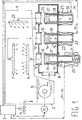
- Figure 1 shows in diagrammatic form a dishwashing machine incorporating the device for changing over and shutting off the flow according to the invention, which is also shown in diagrammatic form.
- the dishwashing machine comprises a washing chamber 1 provided at the bottom with a tank 2 for collecting liquid, into which, on the command of a programming device 3, washing water taken from the mains 4 is admitted.
- the machine also includes a recirculation pump 5 which sucks up liquid from the collecting tank 2 in order to convey it into pipes for feeding spraying devices, which are typically but not necessarily two rotors, a lower 6 and an upper 7 rotor respectively, provided with spraying nozzles which spray with water the dishes accommodated in appropriate baskets (not shown) in the washing chamber.
- spraying devices typically but not necessarily two rotors, a lower 6 and an upper 7 rotor respectively, provided with spraying nozzles which spray with water the dishes accommodated in appropriate baskets (not shown) in the washing chamber.
- the rotors 6 and 7 are of the hydraulic whirler type, and are set in rotation by the thrust exerted by the spraying jets, without the need for motive members devoted to this purpose.
- the pump 5 feeds a distribution chamber 8, above which two pipes 9, 10 open for delivering liquid to the rotors 6, 7 respectively.
- two plugs 11, 12 are accommodated in the chamber 8, and are provided with a cylindrical tang 13, 14 which can slide axially vertically inside a sleeve 15, 16 formed inside the chamber 8.
- a core of permanent magnetic material 17, 18 respectively is fixed, preferably in a recess of the tang.
- the chamber 8, the plugs 11, 12 and the tangs 13, 14 and the sleeves 15, 16 are made of non-magnetic material, preferably of plastic.
- the pressure of the fluid jet in the narrowed section must be lower than the pressure of the fluid jet in the wider section.
- the plugs 11 and 12 maintain the closed position for the entire time that the pump is active and return, by the effect of gravity and by virtue of any thrust exerted by the fluid present in the pipes 9, 10, to the rest position when the pump is deactivated.
- a ferromagnetic core 19 of a suction-type electromagnet 20 is juxtaposed to the magnet 17.
- the core 19 is pressed by a spring 21 against the wall of the chamber 8 and separated from the magnet 17 by a gap of a thickness equal to the thickness of the wall of the chamber.
- the excitation of the electromagnet 20 causes the core 19 to be drawn inside the electromagnet and to move away from the magnet 17 with the formation of a much larger gap between the two elements.
- the excitation of the electromagnet can be effected using a.c. voltage, for example mains voltage, or using d.c. voltage, without distinction, and is to be maintained for a very short time, of the order of a second.
- a.c. voltage for example mains voltage
- d.c. voltage without distinction
- the electric power required is minimal: this is because the work needed to move the plug 11 is performed by the hydraulic flow and the electromagnet 20 has solely the function of controlling temporary release.
- the plug 12 can be actuated by an electromagnetic device identical to that described.
- the plug 12 is controlled by a repulsion-type electromagnet 22 with a fixed core 23.
- the magnetic core 18 is in this case constituted by a magnetic dipole with predetermined orientation, for example with the SOUTH pole facing the wall of the chamber 8.
- This embodiment can advantageously be used in dishwashing machines in which the programmer 3 is of electronic type with a microprocessor instead of electro-mechanical type.
- a d.c. voltage source (5/15V) must be provided for feeding the programmer.
- the same voltage can be used for feeding the electromagnet without any additional cost.
- the function of releasing the plugs can be obtained using a flux-cancellation electromagnet.
- Figure 1 shows a third pipe 24, the end of which opens into the chamber 8 to convey a flow of liquid towards a third spraying device 25 (alternatively, this could also be a waste pipe).
- a plug 26 identical to the previous plugs is juxtaposed at the bottom to the end of the pipe 24 and provided with a tang 27 in which a core 28 made of unmagnetized ferromagnetic material is accommodated.
- the tang 27 is accommodated in a guide sleeve 29.
- a magnetic dipole 29 Arranged outside the chamber 8 and juxtaposed to the core 28 is a magnetic dipole 29, with one pole, for example the SOUTH pole, orientated towards the core 28 so as to exert a force of attraction on the core 28.
- the release electromagnets have, for the sake of simplicity, been shown as being constituted by cylindrical cores accommodated in a winding coil.
- Figures 2 and 3 respectively show a preferred embodiment in a composite vertical section and in a top view along section II-II in Figure 2 of a change-over device.
- the device consists of a body 31 made of moulded plastic material provided at the top with a cylindrical union 32 divided into two semi-cylindrical sectors by a diametral baffle 33.
- the union ends at the bottom in a transverse diaphragm 34, in which two apertures 35, 36 open, which are symmetrical relative to the axis of the union, in the shape of circular sectors with a size of 90° and respectively facing the two semi-cylindrical sectors of the union.
- the body 31 Underneath the diaphragm 34, the body 31 extends to form a housing chamber 41 for two blade-type shut-off levers or clappers 37, 39 which close the apertures 35 (and 37 if present) and 36 respectively.
- the chamber 41 is extended at the bottom in a union 40 which is suitably angled (for example with the axis of the union 40 forming an angle of 45° with the vertical axis of the union 32), for connection to a liquid delivery pipe 42.
- the levers 38, 39 are hinged on a pin 49 parallel to the plane of the diaphragm 34 and outside its extension in such a manner that, by rotation of the levers about the pin 49, these can adopt a position for closing and for opening the ports 35, 36 respectively.
- lever 38 is shown in closed position and the lever 39 in open position which, in the absence of hydrodynamic thrusts, is advantageously adopted under the effect of gravity.
- the chamber 41 is provided on one side with a flanged aperture closed by a flanged plug 46 for support of the levers 38, 39 and the release control devices.
- suction-type electromagnets 43, 44 consist of two identical suction-type electromagnets 43, 44, one of which can be seen in section in Figure 2 and comprises a cylindrical ferromagnetic core 45, which is axially movable in a housing formed by the plug 46 and a winding 47.
- a compression spring 48 presses the core 45 against the head of its housing, towards the chamber 41, moving it away from the winding 47.
- the levers 38, 39 are provided with a housing for a magnet 50, 51.
- the magnet is juxtaposed to the movable core of the associated release device and separated from the latter by the thickness of the flanged plug 46.
- Figure 4 shows in top view the sub-assembly formed by the blade-type levers 38, 39 (shown in horizontal closed position), by the flanged plug 46 and by the pair of suction-type electromagnets 43, 44.
- the levers are pivoted on the pin 49 engaged in a trio of supports 52, 53, 54 which are integral with the flanged plug, in such a manner that the sub-assembly, assembled thus, can be easily fixed, by means of screws or clamping collar, to the body 31.
- An O-ring seal interposed between the flanged plug 46 and the coupling flange of the body 31 ensures perfect sealing of the joint.
- the two blade-type levers are held in open position and a flow admitted into the body of the device through the union 40 can flow freely into the two semi-cylindrical sections of the outlet union 32.
- the outlet union 32 is divided into two semi-cylindrical sections which have to be connected in an accurate manner to the two ducts 56, 57, the connection between the two elements is advantageously achieved using a bayonet coupling of the union 32 on the end 59 of the pipe, bush 58, which for this purpose is provided with coupling pins 60, 61.
- a choking port 37 is provided, which is not shut off by the lever 39, a choked flow will continue to flow out into the pipe 57, limited by the section and by the head losses in the choking port 37.
- the body of the diverter will in this case be provided with two flanged apertures arranged symmetrically in relation to the axis of the unions and closed by two identical release devices similar to that in Figure 4, in which, however, the two blade-type levers have identical dimensions.
Abstract
Description
- The present invention relates to a device for diverting and shutting off the spraying flow, and more generally the flow, in a dishwashing machine, a washing machine in general, and to an associated machine which uses this device.
- It is known that in dishwashing machines the washing water which has been introduced into a collecting tank in a limited quantity, suitably heated and with detergent added, is made to recirculate continuously, by means of at least one centrifugal pump, in spraying devices provided with spraying nozzles through which the washing water is sprayed onto the dishes, whereupon it then falls back into the collecting tank.
- The spraying devices may consist of a number of fixed manifolds, of oscillating arms or of rotary whiners or combinations of these.
- In dishwashing machines, the efficiency of the washing operation is determined essentially by the speed of the spraying jets leaving the nozzles and by their distribution in the washing chamber: ideally, the jets should be capable of scanning all the points of the various surfaces to be washed, a requirement which, to be satisfied, would require the use of a high number of nozzles and of a considerable liquid flow with a high feed pressure.
- To satisfy this requirement, it would be necessary to use a pump of considerable power and recirculation pipes of considerable volumetric capacity, in contrast to the requirements for economy of operation which on the contrary dictate the use of minimum volumes of liquid and of pumps of limited power which are capable of delivering low flows with modest head.
- In order to reconcile these contrasting requirements, it has therefore been proposed to feed selectively, in a mutually exclusive manner and for different periods of time, each of the various spraying manifolds, oscillating arms or rotary whirlers with a limited flow of liquid which can be delivered at the necessary pressure by one or more pumps of reduced power and size.
- Preferably, to allow the various spraying circuits to be fed by a single pump, use is made of flow-diverting devices.
- Various types of flow diverters have been proposed which only partly satisfy the requirements of reliability, simplicity of construction, operating economy and low cost which are necessary for use in dishwashing machines.
- Electromagnetic shut-off and diversion valves consume considerable power, require constant maintenance and involve a high risk of loss of liquid or of ageing and breaking of the elastic diaphragm separating the electrical parts from the hydraulic circuit, if of the diaphragm type.
- Thermoelectric actuators, in which the mechanical actuation is brought about by the expansion of appropriate substances which are appropriately heated electrically, are more economical and require a lower feed power, but have considerable thermal inertia which is irreconcilable with the requirement for rapid control of flow diversion.
- Shut-off and diversion valves which are actuated by an electric motor have reduced consumption, concentrated solely in those periods of closing/opening action or flow change-overs, but are extremely expensive and do not reliably solve the problem of separating external actuating members and moving shut-off members inside the hydraulic circuits.
- Flow-diverting devices of automatic type have also been proposed, which use the flow of liquid induced by the pump to actuate a hydraulic wheel which, directly or via a suitable reduction in the number of revolutions, moves a diaphragm for diverting the flow.
- In this case, no external control device is needed, but the flow-diverting action of the diverters is uncontrollable, and to a great extent, random, in addition to being slow and gradual instead of the "ON-OFF" type.
- The present invention overcomes these disadvantages and provides a device for diverting and shuting-off the spraying flow in dishwashing machines, which is simple and reliable, of very low consumption and of low cost, of maximum safety and of particularly rapid action, and which imperviously separates the external control members from the moving shut-off members inside the hydraulic circuit.
- These results are achieved by a diverting device in which a plurality of shut-off diaphragms or plugs, each for a different flow path, are held in an open position by the action of magnetic attraction exerted between a magnetic element integral with the diaphragm and the core of an electromagnet outside the hydraulic circuit and separated from the magnet by a hydraulic separating wall constituting a gap for the magnetic circuit.
- The temporary excitation of the electromagnet, which may be of the moving core type or the repulsion type, or the flux-cancellation type, by reducing the mutual attraction force or replacing it with a repulsive force, between magnetic element and core, allows the associated diaphragm to move from a position in which it opens, to a position in which it closes a flow path through the effect of a hydrodynamic thrust exerted on the diaphragm by a flow of liquid initiated by a circulation pump.
- In this manner, a plurality of flow paths, all fed by one and the same delivery pipe, can be closed individually, with minimum consumption of power.
- The characteristics and the advantages of the invention will emerge more clearly from the description which follows of a preferred embodiment and its variants which is given with reference to the attached drawings, in which:
- Fig. 1 shows diagrammatically a dishwashing machine incorporating the device for diverting and shutting off the flow according to the invention, which is also shown in diagrammatic form;
- Fig. 2 shows in vertical section on a number of planes, along the section I-I in Figure 3, a preferred embodiment of the device for diverting and shutting off the flow according to the present invention;
- Fig. 3 shows in section, according to the view II-II in Figure 2, the diverting device in Fig. 2;
- Fig. 4 shows in a top view a control sub-assembly of the device in Figures 2 and 3.
- For better comprehension of the invention, Figure 1 shows in diagrammatic form a dishwashing machine incorporating the device for changing over and shutting off the flow according to the invention, which is also shown in diagrammatic form.
- The dishwashing machine comprises a washing chamber 1 provided at the bottom with a
tank 2 for collecting liquid, into which, on the command of a programming device 3, washing water taken from the mains 4 is admitted. - The machine also includes a recirculation pump 5 which sucks up liquid from the collecting
tank 2 in order to convey it into pipes for feeding spraying devices, which are typically but not necessarily two rotors, a lower 6 and an upper 7 rotor respectively, provided with spraying nozzles which spray with water the dishes accommodated in appropriate baskets (not shown) in the washing chamber. - Heating elements and devices for adding detergent to the washing liquid, together with filtering systems, although normally provided and known per se, are not shown since they are irrelevant to the aims of the invention.
- Typically but not necessarily, the rotors 6 and 7 are of the hydraulic whirler type, and are set in rotation by the thrust exerted by the spraying jets, without the need for motive members devoted to this purpose.
- For improved washing efficiency, which is compatible with the use of a reduced-consumption pump 5, it is necessary, as already stated, to feed the two rotors selectively in different time periods.
- To this end, according to the invention, the pump 5 feeds a
distribution chamber 8, above which twopipes - Facing the ends of the
pipes plugs chamber 8, and are provided with acylindrical tang sleeve chamber 8. - At the opposite end of the
tangs plugs magnetic material - The
chamber 8, theplugs tangs sleeves - In the rest state, the
tangs chamber 8 and theplugs chamber 8. - It is known that if a fluid jet is subjected to a reduction in section, its speed must necessarily increase, by virtue of the principle of continuity of flow.
- Consequently, by virtue of Bernoulli's theorem, the pressure of the fluid jet in the narrowed section must be lower than the pressure of the fluid jet in the wider section.
- Therefore, on activation of the pump 5, a flow is initiated into the
chamber 8 which flows into thepipes plugs respective flow pipes plugs - Since the pressure downstream of the end of the
pipes chamber 8 by the head of the pump 5, theplugs pipes - To prevent the
plug 11 being drawn towards the end of thepipe 9 when the pump is activated, and to enable it selectively, outside thechamber 8, aferromagnetic core 19 of a suction-type electromagnet 20 is juxtaposed to themagnet 17. - The
core 19 is pressed by aspring 21 against the wall of thechamber 8 and separated from themagnet 17 by a gap of a thickness equal to the thickness of the wall of the chamber. - Under these conditions, the magnetic attraction force which is exerted between
magnet 17 andcore 19 prevents theplug 11 from being drawn back towards thepipe 9, under all pressure and flow conditions which the pump may establish in thechamber 8. - The excitation of the
electromagnet 20 causes thecore 19 to be drawn inside the electromagnet and to move away from themagnet 17 with the formation of a much larger gap between the two elements. - Under these conditions, the force of attraction which is exerted between
magnet 17 andcore 19 is weakened considerably and is no longer sufficient to prevent theplug 11 from being drawn back hydrodynamically when the pump is activated. - The excitation of the electromagnet can be effected using a.c. voltage, for example mains voltage, or using d.c. voltage, without distinction, and is to be maintained for a very short time, of the order of a second.
- The electric power required is minimal: this is because the work needed to move the
plug 11 is performed by the hydraulic flow and theelectromagnet 20 has solely the function of controlling temporary release. - This can be effected in a synchronized manner with the starting of the pump 5 or even once the pump has already been started.
- The
plug 12 can be actuated by an electromagnetic device identical to that described. - To reduce the number of moving parts to a minimum and to simplify as far as possible the release device, in Fig. 1, to provide another exemplary embodiment, the
plug 12 is controlled by a repulsion-type electromagnet 22 with afixed core 23. - The
magnetic core 18 is in this case constituted by a magnetic dipole with predetermined orientation, for example with the SOUTH pole facing the wall of thechamber 8. - By exciting the winding of the
electromagnet 22 with direct current of predetermined direction, it is possible to magnetize thecore 23 in such a manner that its end facing the wall of thechamber 8 also takes on SOUTH polarity. - In this way, while the
core 18 is normally attracted towards thecore 23, when theelectromagnet 22 is excited a repulsive force is exerted between the twocores plug 12 to be drawn back towards the end of thepipe 10. - This embodiment can advantageously be used in dishwashing machines in which the programmer 3 is of electronic type with a microprocessor instead of electro-mechanical type.
- In this case, a d.c. voltage source (5/15V) must be provided for feeding the programmer. The same voltage can be used for feeding the electromagnet without any additional cost.
- According to another variant, the function of releasing the plugs can be obtained using a flux-cancellation electromagnet.
- For example, Figure 1 shows a
third pipe 24, the end of which opens into thechamber 8 to convey a flow of liquid towards a third spraying device 25 (alternatively, this could also be a waste pipe). - A
plug 26 identical to the previous plugs is juxtaposed at the bottom to the end of thepipe 24 and provided with atang 27 in which acore 28 made of unmagnetized ferromagnetic material is accommodated. - The
tang 27 is accommodated in aguide sleeve 29. - Arranged outside the
chamber 8 and juxtaposed to thecore 28 is amagnetic dipole 29, with one pole, for example the SOUTH pole, orientated towards thecore 28 so as to exert a force of attraction on thecore 28. - A winding 30, wound around the
dipole 29, when excited by a direct current of suitable direction, neutralizes or cancels the magnetic flux generated by the dipole and cancels the force of attraction exerted on thecore 28, in such a manner that the hydrodynamic action exerted by a flow of liquid in thechamber 8 can draw theplug 26 towards the end of thepipe 24. - It is therefore clear that the selective activation of the various electromagnets makes it possible to feed only one of the
pipes - Even when the pump has been started, without deactivating it, it is possible to close any one of the pipes which were previously open.
- The only operation which requires the deactivation of the pump is the opening of any one of the pipes if closed.
- In Figure 3, the release electromagnets have, for the sake of simplicity, been shown as being constituted by cylindrical cores accommodated in a winding coil.
- In practice, for greater efficiency, they can include yokes for closing up the magnetic circuit.
- Even the arrangement of the plugs so as to ensure the rest position by the effect of gravity alone is not essential: it is possible to provide elastic means for returning to the rest position with the sole condition that the hydraulic thrust exerted on the plugs by the pump when operating and by the consequent flow prevails over the elastic return force.
- Even the use of tangs which can slide axially in sleeves to ensure the mobility of the plugs is purely exemplary. Other forms of restraint can be adopted to reduce possible friction to a minimum.
- Figures 2 and 3 respectively show a preferred embodiment in a composite vertical section and in a top view along section II-II in Figure 2 of a change-over device.
- The device consists of a
body 31 made of moulded plastic material provided at the top with acylindrical union 32 divided into two semi-cylindrical sectors by adiametral baffle 33. - The union ends at the bottom in a
transverse diaphragm 34, in which twoapertures - It is also possible to provide in the diaphragm 34 a
third aperture 37 for choking the flow, as will be seen below. - Underneath the
diaphragm 34, thebody 31 extends to form a housing chamber 41 for two blade-type shut-off levers orclappers - The chamber 41 is extended at the bottom in a
union 40 which is suitably angled (for example with the axis of theunion 40 forming an angle of 45° with the vertical axis of the union 32), for connection to aliquid delivery pipe 42. - The
levers pin 49 parallel to the plane of thediaphragm 34 and outside its extension in such a manner that, by rotation of the levers about thepin 49, these can adopt a position for closing and for opening theports - In Figure 2, the
lever 38 is shown in closed position and thelever 39 in open position which, in the absence of hydrodynamic thrusts, is advantageously adopted under the effect of gravity. - The chamber 41 is provided on one side with a flanged aperture closed by a
flanged plug 46 for support of thelevers - These consist of two identical suction-
type electromagnets ferromagnetic core 45, which is axially movable in a housing formed by theplug 46 and a winding 47. - A
compression spring 48 presses the core 45 against the head of its housing, towards the chamber 41, moving it away from the winding 47. - As can be seen from Figure 2, the
levers magnet 50, 51. When the levers are in rest or open position, the magnet is juxtaposed to the movable core of the associated release device and separated from the latter by the thickness of theflanged plug 46. - Figure 4 shows in top view the sub-assembly formed by the blade-
type levers 38, 39 (shown in horizontal closed position), by theflanged plug 46 and by the pair of suction-type electromagnets - The levers are pivoted on the
pin 49 engaged in a trio ofsupports body 31. - An O-ring seal interposed between the
flanged plug 46 and the coupling flange of thebody 31 ensures perfect sealing of the joint. - The functioning of the change-over device described is completely identical to the previous one.
- If the two
electromagnets union 40 can flow freely into the two semi-cylindrical sections of theoutlet union 32. - This can be connected to a pipe or
bush 59 with twoducts - As the
outlet union 32 is divided into two semi-cylindrical sections which have to be connected in an accurate manner to the twoducts union 32 on theend 59 of the pipe,bush 58, which for this purpose is provided with coupling pins 60, 61. - A resilient ring or an O-ring 62, interposed between an internal shoulder of the
union 32 and theend 59 of thepipe 58 ensures the imperviousness of the connection to the outside. - In this manner, the correct mutual angular positioning of the
union 32 and of thepipe 58 relative to their common axis is ensured. - If the electromagnet associated with the
lever 39 is excited, thelever 39, drawn by the flow of liquid, shuts off theaperture 36 and prevents the liquid from flowing out into thepipe 57. - The whole flow of liquid is therefore forced to flow out into the
pipe 56. - If, as shown in Figure 3, a choking
port 37 is provided, which is not shut off by thelever 39, a choked flow will continue to flow out into thepipe 57, limited by the section and by the head losses in the chokingport 37. - If the electromagnet associated with the
lever 38 is excited, theport 35 is shut off and the liquid can flow out into thepipe 57. - If both the
electromagnets levers diaphragm 34. - This example, however, is of little practical use because the same effect can be achieved by deactivating the pump, but its use cannot be ruled out altogether: for example, it can be used to shut off the flow of liquid abruptly more quickly than allowed by the inertia of the pump and the volume of liquid or for filling the tank with a greater volume of liquid by using a single steady pressure level adjustment.
- The description above relates to a preferred embodiment but it is clear that it can be subjected to many variations.
- For example, it is possible to produce a four-way flow-diverting device, with a delivery union arranged below and axially aligned with the outlet union, divided into four cylindrical sectors, for coupling to four separate pipes.
- The body of the diverter will in this case be provided with two flanged apertures arranged symmetrically in relation to the axis of the unions and closed by two identical release devices similar to that in Figure 4, in which, however, the two blade-type levers have identical dimensions.
Claims (10)
- Device for diverting and shutting off the flow of liquid in particular for a dishwashing machine, and a washing machine in general, comprising:- a non-magnetic body (8, 31) forming an internal chamber (41) separated from the outside by a wall of said body and having a liquid inlet (40) and a plurality of liquid outlets (9, 10, 24, 35, 36), each provided with a sealing plug (11, 12, 26, 38, 39) which is accommodated in said chamber (8, 41) and is movable between a position for closing and a position for opening the associated outlet,- each of said plugs being provided with a ferromagnetic element (17, 18, 28, 50, 51) arranged adjacent to said wall for said opening position of the associated plug, and moved away from said wall for said closing position, and- a plurality of electromagnets (19, 20, 22, 23, 29, 30, 43, 44) arranged outside said body and each associated with one of said plugs for exerting, if unexcited, a force of magnetic attraction on said ferromagnetic element of the associated plug, if said associated plug is in the open position, said force of attraction holding the associated plug in open position even in the presence of a flow of liquid in said chamber, the excitation of each of said electromagnets reducing the force of attraction exerted on the ferromagnetic element of the associated plug and allowing said plug to adopt the closed position through the effect of the hydrodynamic thrust exerted by a flow of liquid in said chamber.
- Device for diverting and shutting off flow according to Claim 1, in which said ferromagnetic element (17, 50, 51) of said plugs is a permanent magnet and said electromagnets (20, 43, 44) are moving-core suction-type electromagnets (19, 45).
- Device for diverting and shutting off flow according to Claim 1, in which said ferromagnetic element of said plugs is a permanent magnet (18) and said electromagnets are fixed-core (23) electromagnets (22) excited by direct current, which polarizes said fixed core (23) so as to exert a repulsive force on the permanent magnet (18) of the associated plug.
- Device for diverting and shutting off flow according to Claim 1, in which said ferromagnetic element (28) of said plugs is not permanently megnetizable, and said electromagnets are flux-cancellation electromagnets (30) which are excited by direct current and have a fixed core (29) comprising a permanent magnet.
- Device for diverting and shutting off flow according to the preceding claims, in which said plugs are blade-type levers or clappers (38, 39) hinged on a pin (52).
- Device for diverting and shutting off flow according to Claim 5, in which said fluid outlets are cylindrical sectors (35, 36) of a cylindrical outlet union (32) divided into a number of outlet ducts by at least one internal baffle (33).
- Device for diverting and shutting off flow according to Claim 6, in which said body (31) is provided with a flanged aperture for coupling to a flanged plug (46) for closing said aperture and for support for said plurality of blade-type levers (38, 39) and electromagnets (43, 44).
- Device for diverting and shutting off flow according to Claim 7, in which said body (31) is provided with a cylindrical inlet union (40) with an axis forming an angle relative to the axis of said outlet union (32).
- Device for diverting and shutting off flow according to Claim 6, 7 or 8, in which said cylindrical outlet union (32) comprises means for bayonet coupling to a pipe, or outlet bush (58).
- Washing machine, dishwashing machine or clothes-washing machine, of the type in which the liquid admitted into a tank (2) of said machine is conveyed by a pump (5) into one or more pipes which are opened selectively by a flow-diverting device, characterized in that said flow-diverting device is a device according to one of the preceding claims.
Applications Claiming Priority (2)
| Application Number | Priority Date | Filing Date | Title |
|---|---|---|---|
| ITMI960140 | 1996-01-26 | ||
| IT96MI000140A IT1282071B1 (en) | 1996-01-26 | 1996-01-26 | DEVIATION AND INTERCEPTION DEVICE OF SPRAYING FLOW FOR WASHING MACHINE WASHING MACHINE IN GENERAL |
Publications (3)
| Publication Number | Publication Date |
|---|---|
| EP0786230A2 true EP0786230A2 (en) | 1997-07-30 |
| EP0786230A3 EP0786230A3 (en) | 1998-08-05 |
| EP0786230B1 EP0786230B1 (en) | 2003-01-15 |
Family
ID=11373044
Family Applications (1)
| Application Number | Title | Priority Date | Filing Date |
|---|---|---|---|
| EP96202595A Expired - Lifetime EP0786230B1 (en) | 1996-01-26 | 1996-09-17 | Device for diverting and shutting-off the spraying flow in a dishwashing machine, a washing machine in general and associated machine which uses this device |
Country Status (3)
| Country | Link |
|---|---|
| EP (1) | EP0786230B1 (en) |
| DE (1) | DE69625787T2 (en) |
| IT (1) | IT1282071B1 (en) |
Cited By (16)
| Publication number | Priority date | Publication date | Assignee | Title |
|---|---|---|---|---|
| EP1240863A2 (en) * | 2001-02-07 | 2002-09-18 | T & P S.p.A. | Bypass valve for washing machine and relative methods of application |
| EP1264570A1 (en) * | 2000-02-14 | 2002-12-11 | Matsushita Electric Industrial Co., Ltd. | Washing machine |
| US7331356B2 (en) | 2003-06-17 | 2008-02-19 | Whirlpool Corporation | Multiple wash zone dishwater |
| US7475696B2 (en) | 2003-06-17 | 2009-01-13 | Whirlpool Corporation | Dishwasher having valved third-level sprayer |
| US7523758B2 (en) | 2003-06-17 | 2009-04-28 | Whirlpool Corporation | Dishwasher having rotating zone wash sprayer |
| CN1857155B (en) * | 2005-04-14 | 2010-05-12 | 松下电器产业株式会社 | Dishware washer |
| WO2010091974A2 (en) | 2009-02-16 | 2010-08-19 | BSH Bosch und Siemens Hausgeräte GmbH | Household dishwashing machine and method for supplying one or a plurality of rinsing fluid spraying arrangements |
| US8347898B2 (en) | 2009-04-30 | 2013-01-08 | Whirlpool Corporation | Dishwasher with rotating zone wash sprayers |
| ITRN20110071A1 (en) * | 2011-10-20 | 2013-04-21 | Indesit Co Spa | WASHING AND / OR DRYING APPLIANCES. |
| US9119517B2 (en) | 2011-10-17 | 2015-09-01 | Whirlpool Corporation | Dishwasher having spray manifold and method for controlling same |
| CN105212866A (en) * | 2015-09-30 | 2016-01-06 | 宁波安佳卫厨电器有限公司 | A kind of water knockout drum of dish-washing machine |
| US9259138B2 (en) | 2010-12-07 | 2016-02-16 | Whirlpool Corporation | Dishwasher with auxiliary spray system having removable sprayers |
| US9713414B2 (en) | 2013-06-21 | 2017-07-25 | Whirlpool Corporation | Dishwasher having a conduit framework |
| US10076224B2 (en) | 2014-01-20 | 2018-09-18 | Whirlpool Corporation | Dishwasher |
| IT201900010245A1 (en) * | 2019-06-27 | 2020-12-27 | Silanos S R L | Rinsing system for dishwashing machines, and dishwashing machine comprising this rinsing system. |
| EP3868279A4 (en) * | 2018-10-16 | 2022-08-10 | Foshan Shunde Midea Washing Appliances Manufacturing Co., Ltd. | Dishwasher |
Citations (3)
| Publication number | Priority date | Publication date | Assignee | Title |
|---|---|---|---|---|
| EP0547011A1 (en) * | 1991-12-11 | 1993-06-16 | Colged S.R.L. | A washing method for a dishwashing machine of industrial type |
| DE4241497A1 (en) * | 1992-12-09 | 1994-06-16 | Bosch Siemens Hausgeraete | Domestic dishwashing machine - performs check on function of pump which involves timing of intervals between start of pumping and operation of reed switch by permanent magnet in blocking valve |
| DE19626823A1 (en) * | 1995-07-04 | 1997-01-09 | Elbi Int Spa | Electric through=flow stop valve for dishwasher - has two elements made of ferromagnetic material, mobile blocking element and solenoid |
-
1996
- 1996-01-26 IT IT96MI000140A patent/IT1282071B1/en active IP Right Grant
- 1996-09-17 DE DE69625787T patent/DE69625787T2/en not_active Expired - Fee Related
- 1996-09-17 EP EP96202595A patent/EP0786230B1/en not_active Expired - Lifetime
Patent Citations (3)
| Publication number | Priority date | Publication date | Assignee | Title |
|---|---|---|---|---|
| EP0547011A1 (en) * | 1991-12-11 | 1993-06-16 | Colged S.R.L. | A washing method for a dishwashing machine of industrial type |
| DE4241497A1 (en) * | 1992-12-09 | 1994-06-16 | Bosch Siemens Hausgeraete | Domestic dishwashing machine - performs check on function of pump which involves timing of intervals between start of pumping and operation of reed switch by permanent magnet in blocking valve |
| DE19626823A1 (en) * | 1995-07-04 | 1997-01-09 | Elbi Int Spa | Electric through=flow stop valve for dishwasher - has two elements made of ferromagnetic material, mobile blocking element and solenoid |
Cited By (36)
| Publication number | Priority date | Publication date | Assignee | Title |
|---|---|---|---|---|
| EP1264570A1 (en) * | 2000-02-14 | 2002-12-11 | Matsushita Electric Industrial Co., Ltd. | Washing machine |
| EP1264570A4 (en) * | 2000-02-14 | 2007-05-30 | Matsushita Electric Ind Co Ltd | Washing machine |
| US7270132B2 (en) | 2000-02-14 | 2007-09-18 | Matsushita Electric Industrial Co., Ltd. | Washer |
| EP1240863A2 (en) * | 2001-02-07 | 2002-09-18 | T & P S.p.A. | Bypass valve for washing machine and relative methods of application |
| EP1240863A3 (en) * | 2001-02-07 | 2002-12-18 | T & P S.p.A. | Bypass valve for washing machine and relative methods of application |
| US8753454B2 (en) | 2003-06-17 | 2014-06-17 | Whirlpool Corporation | Dishwasher |
| US9615720B2 (en) | 2003-06-17 | 2017-04-11 | Whirlpool Corporation | Dishwasher |
| US7475696B2 (en) | 2003-06-17 | 2009-01-13 | Whirlpool Corporation | Dishwasher having valved third-level sprayer |
| US7523758B2 (en) | 2003-06-17 | 2009-04-28 | Whirlpool Corporation | Dishwasher having rotating zone wash sprayer |
| US7594513B2 (en) | 2003-06-17 | 2009-09-29 | Whirlpool Corporation | Multiple wash zone dishwasher |
| US10238266B2 (en) | 2003-06-17 | 2019-03-26 | Whirlpool Corporation | Dishwasher |
| US7445013B2 (en) | 2003-06-17 | 2008-11-04 | Whirlpool Corporation | Multiple wash zone dishwasher |
| US9474434B2 (en) | 2003-06-17 | 2016-10-25 | Whirlpool Corporation | Dishwasher |
| US8871031B2 (en) | 2003-06-17 | 2014-10-28 | Whirlpool Corporation | Dishwasher |
| US8808467B2 (en) | 2003-06-17 | 2014-08-19 | Whirlpool Corporation | Dishwasher |
| US8801868B2 (en) | 2003-06-17 | 2014-08-12 | Whirlpool Corporation | Dishwasher |
| US8454762B2 (en) | 2003-06-17 | 2013-06-04 | Whirlpool Corporation | Dishwasher |
| US8454763B2 (en) | 2003-06-17 | 2013-06-04 | Whirlpool Corporation | Dishwasher |
| US7331356B2 (en) | 2003-06-17 | 2008-02-19 | Whirlpool Corporation | Multiple wash zone dishwater |
| US8764908B2 (en) | 2003-06-17 | 2014-07-01 | Whirlpool Corporation | Method of controlling the operation of a dishwasher |
| CN1857155B (en) * | 2005-04-14 | 2010-05-12 | 松下电器产业株式会社 | Dishware washer |
| WO2010091974A3 (en) * | 2009-02-16 | 2010-12-29 | BSH Bosch und Siemens Hausgeräte GmbH | Household dishwashing machine and method for supplying one or a plurality of rinsing fluid spraying arrangements |
| WO2010091990A3 (en) * | 2009-02-16 | 2010-12-23 | BSH Bosch und Siemens Hausgeräte GmbH | Dishwasher, in particular household dishwasher |
| WO2010091974A2 (en) | 2009-02-16 | 2010-08-19 | BSH Bosch und Siemens Hausgeräte GmbH | Household dishwashing machine and method for supplying one or a plurality of rinsing fluid spraying arrangements |
| US8347898B2 (en) | 2009-04-30 | 2013-01-08 | Whirlpool Corporation | Dishwasher with rotating zone wash sprayers |
| US9259138B2 (en) | 2010-12-07 | 2016-02-16 | Whirlpool Corporation | Dishwasher with auxiliary spray system having removable sprayers |
| US9119517B2 (en) | 2011-10-17 | 2015-09-01 | Whirlpool Corporation | Dishwasher having spray manifold and method for controlling same |
| US10499787B2 (en) | 2011-10-17 | 2019-12-10 | Whirlpool Corporation | Dishwasher having spray manifold |
| ITRN20110071A1 (en) * | 2011-10-20 | 2013-04-21 | Indesit Co Spa | WASHING AND / OR DRYING APPLIANCES. |
| US9713414B2 (en) | 2013-06-21 | 2017-07-25 | Whirlpool Corporation | Dishwasher having a conduit framework |
| US10076224B2 (en) | 2014-01-20 | 2018-09-18 | Whirlpool Corporation | Dishwasher |
| CN105212866B (en) * | 2015-09-30 | 2018-06-19 | 宁波安佳卫厨电器有限公司 | A kind of control method of the water knockout drum of dish-washing machine |
| CN105212866A (en) * | 2015-09-30 | 2016-01-06 | 宁波安佳卫厨电器有限公司 | A kind of water knockout drum of dish-washing machine |
| EP3868279A4 (en) * | 2018-10-16 | 2022-08-10 | Foshan Shunde Midea Washing Appliances Manufacturing Co., Ltd. | Dishwasher |
| IT201900010245A1 (en) * | 2019-06-27 | 2020-12-27 | Silanos S R L | Rinsing system for dishwashing machines, and dishwashing machine comprising this rinsing system. |
| EP3756526A1 (en) * | 2019-06-27 | 2020-12-30 | Silanos S.r.l. | Rinsing system for dishwashers, and dishwasher comprising the rinsing system |
Also Published As
| Publication number | Publication date |
|---|---|
| ITMI960140A0 (en) | 1996-01-26 |
| DE69625787D1 (en) | 2003-02-20 |
| EP0786230A3 (en) | 1998-08-05 |
| ITMI960140A1 (en) | 1997-07-26 |
| DE69625787T2 (en) | 2003-10-02 |
| EP0786230B1 (en) | 2003-01-15 |
| IT1282071B1 (en) | 1998-03-09 |
Similar Documents
| Publication | Publication Date | Title |
|---|---|---|
| EP0786230B1 (en) | Device for diverting and shutting-off the spraying flow in a dishwashing machine, a washing machine in general and associated machine which uses this device | |
| US8783306B2 (en) | Device for delivering liquids | |
| JP2010512199A (en) | Beverage preparation device with pinch valve | |
| EP3120060A1 (en) | Bistable electric valve, in particular for a system for recovering petrol vapours in a motor vehicle | |
| DE10062207B4 (en) | Pump with selectable suction openings | |
| US10024453B2 (en) | Dual acting solenoid valve using bi-stable permanent magnet activation for energy efficiency and power versatility | |
| GB2190983A (en) | Switch valve | |
| US20020000255A1 (en) | Balanced fluid control valve | |
| US10290449B2 (en) | Electric switch | |
| US3788347A (en) | Single hose coupling system | |
| CN101262808A (en) | Domestic dishwasher | |
| EP1381803A1 (en) | Electromagnetically operated valve | |
| US6347645B2 (en) | Fluid dynamic diverter valve for an appliance | |
| EP3179488B1 (en) | A magnetic circuit switching device with single-sided attraction | |
| GB2028160A (en) | Water softening apparatus | |
| GB2320311A (en) | Magnetically latched diverter valves | |
| CA1229029A (en) | Venturi power supply and actuator system | |
| EP1024504B1 (en) | Improved electromagnetic actuator for washing and similar machines | |
| US2974923A (en) | Equipment for distributing fluid and valve for operating the same | |
| CN208651765U (en) | A kind of PVC valve control device | |
| JPS61136074A (en) | Solenoid operated valve for fluid | |
| US4561344A (en) | Electro-fluidic control device | |
| SU369330A1 (en) | SOLENOID VALVE | |
| JP3251085B2 (en) | solenoid valve | |
| US20200071921A1 (en) | Toilet electromagnetic distributor |
Legal Events
| Date | Code | Title | Description |
|---|---|---|---|
| PUAI | Public reference made under article 153(3) epc to a published international application that has entered the european phase |
Free format text: ORIGINAL CODE: 0009012 |
|
| AK | Designated contracting states |
Kind code of ref document: A2 Designated state(s): DE FR IT |
|
| PUAL | Search report despatched |
Free format text: ORIGINAL CODE: 0009013 |
|
| AK | Designated contracting states |
Kind code of ref document: A3 Designated state(s): DE FR IT |
|
| 17P | Request for examination filed |
Effective date: 19981005 |
|
| GRAG | Despatch of communication of intention to grant |
Free format text: ORIGINAL CODE: EPIDOS AGRA |
|
| 17Q | First examination report despatched |
Effective date: 20020515 |
|
| GRAG | Despatch of communication of intention to grant |
Free format text: ORIGINAL CODE: EPIDOS AGRA |
|
| GRAH | Despatch of communication of intention to grant a patent |
Free format text: ORIGINAL CODE: EPIDOS IGRA |
|
| GRAH | Despatch of communication of intention to grant a patent |
Free format text: ORIGINAL CODE: EPIDOS IGRA |
|
| GRAA | (expected) grant |
Free format text: ORIGINAL CODE: 0009210 |
|
| AK | Designated contracting states |
Kind code of ref document: B1 Designated state(s): DE FR IT |
|
| REF | Corresponds to: |
Ref document number: 69625787 Country of ref document: DE Date of ref document: 20030220 Kind code of ref document: P |
|
| ET | Fr: translation filed | ||
| PLBE | No opposition filed within time limit |
Free format text: ORIGINAL CODE: 0009261 |
|
| STAA | Information on the status of an ep patent application or granted ep patent |
Free format text: STATUS: NO OPPOSITION FILED WITHIN TIME LIMIT |
|
| 26N | No opposition filed |
Effective date: 20031016 |
|
| PGFP | Annual fee paid to national office [announced via postgrant information from national office to epo] |
Ref country code: DE Payment date: 20050818 Year of fee payment: 10 |
|
| PGFP | Annual fee paid to national office [announced via postgrant information from national office to epo] |
Ref country code: FR Payment date: 20050831 Year of fee payment: 10 |
|
| PG25 | Lapsed in a contracting state [announced via postgrant information from national office to epo] |
Ref country code: DE Free format text: LAPSE BECAUSE OF NON-PAYMENT OF DUE FEES Effective date: 20070403 |
|
| REG | Reference to a national code |
Ref country code: FR Ref legal event code: ST Effective date: 20070531 |
|
| PG25 | Lapsed in a contracting state [announced via postgrant information from national office to epo] |
Ref country code: FR Free format text: LAPSE BECAUSE OF NON-PAYMENT OF DUE FEES Effective date: 20061002 |
|
| PGFP | Annual fee paid to national office [announced via postgrant information from national office to epo] |
Ref country code: IT Payment date: 20120917 Year of fee payment: 17 |
|
| PG25 | Lapsed in a contracting state [announced via postgrant information from national office to epo] |
Ref country code: IT Free format text: LAPSE BECAUSE OF NON-PAYMENT OF DUE FEES Effective date: 20130917 |