EP0780097A2 - Laser devices and methods for medical, especially dental use - Google Patents
Laser devices and methods for medical, especially dental use Download PDFInfo
- Publication number
- EP0780097A2 EP0780097A2 EP96890199A EP96890199A EP0780097A2 EP 0780097 A2 EP0780097 A2 EP 0780097A2 EP 96890199 A EP96890199 A EP 96890199A EP 96890199 A EP96890199 A EP 96890199A EP 0780097 A2 EP0780097 A2 EP 0780097A2
- Authority
- EP
- European Patent Office
- Prior art keywords
- laser
- radiation
- dental
- laser device
- head
- Prior art date
- Legal status (The legal status is an assumption and is not a legal conclusion. Google has not performed a legal analysis and makes no representation as to the accuracy of the status listed.)
- Withdrawn
Links
Images

Classifications
-
- A—HUMAN NECESSITIES
- A61—MEDICAL OR VETERINARY SCIENCE; HYGIENE
- A61C—DENTISTRY; APPARATUS OR METHODS FOR ORAL OR DENTAL HYGIENE
- A61C1/00—Dental machines for boring or cutting ; General features of dental machines or apparatus, e.g. hand-piece design
- A61C1/0046—Dental lasers
Definitions
- the present invention relates in general to laser systems for use in medicine and in particular to laser devices and methods which are suitable for use in dental medicine, such as in the treatment of abscesses, carious areas and also when cutting or removing hard or soft tissue.
- Laser radiation is currently used in medicine and dental medicine to perform a variety of procedures, including procedures that involve cutting or vaporizing soft tissue including gums, nerve tissue, and tooth pulp. It has also been shown that laser radiation of the appropriate wavelength and energy density can cut hard tissue including bone, tooth enamel, dentin and dental fillings as well as demineralized hard tissues such as carious tooth tissue. Laser radiation can also be used to cut tartar, soft or hard plaque, and most materials that form on tooth surfaces, as well as similar materials that form in body channels, including blood vessels and urinary vessels.
- the effectiveness of laser radiation on a particular tissue largely depends on the wavelength and intensity of the radiation and the form in which the radiation is delivered to the tissue.
- the radiation is delivered in one of two ways, either as a continuous wave or as a pulsating wave.
- the type of laser to be used for a specific application is determined by the intensity and wavelength of the laser light, which has the greatest effectiveness for this procedure. If pulsed radiation is preferred for the process, then the optimal values for the pulse duration and the repetition frequency can be determined.
- the energy delivered by each pulse is the product of the laser strength and the pulse duration.
- the energy density with which each pulse is applied to the tissue to be treated is the total energy transferred divided by the size of the irradiation area on the tissue. The energy density is an important parameter when determining the effect of laser radiation.
- the possibility of delivering the radiation to the desired location is of substantial importance.
- handpieces are used in conjunction with optical conductors that direct the laser radiation from the laser itself to the handpiece.
- One of the problems associated with the use of optical fibers for the transmission of laser beams is that, at certain wavelengths of the laser beams, the material to be used for the fiber cable can be brittle and therefore tends to break.
- the coherence of the laser radiation is deteriorated by the passage through a fiber.
- hand-held lasers that are small enough to be used in the dental field and that do not use optical fibers have other problems. Without optical fiber, the surgeon must focus the laser radiation on the area to be treated. It would be very difficult for a dental surgeon to maintain the precise location and distance with a steady hand. However, both are necessary in order to optimally guide the focal point of the laser radiation in the course of an intervention. The difficulty can be even greater, since the energy that is emitted by dental lasers is usually in the infrared range. It would be extremely difficult for a surgeon to correctly direct the focus of laser beams to the point to be treated if the beams are invisible.
- Laser radiation with a wavelength of less than 3 microns includes those generated by the Nd: YAG lasers (fundamental wavelength 1.06 microns) and the Er: YAG lasers (fundamental wavelength 2.94 microns). Both of these laser beam shapes are able to cut different types of tissue, although each of these two types does it in a slightly different way. The differences result partly from the fact that water is one has a very low absorption coefficient for laser radiation with a wavelength of 1.06 micrometers and a relatively large absorption coefficient for radiation at the wavelength of 2.94 micrometers. It is known in the prior art that suitable lasers for dental applications are the Er: YAG and to a lesser extent the Nd: YAG lasers. The reason for this is that the Er: YAG radiation coincides with a main absorption band of water.
- Erbium is a chemical element of the rare earth group that occurs with yttrium and is also used as a source of laser radiation.
- the Er: YAG lasers are pulsed solid-state lasers with a maximum emission in the middle infrared range at 2.94 micrometers, in which water is strongly absorbed.
- Laser surgery, which is performed with Er: YAG lasers, causes water in the illuminated tissue to absorb the radiation energy.
- Hard surfaces such as teeth although they contain very little water, are also heated by absorption of the laser radiation.
- laser radiation is applied to a tooth, in order to avoid damage to the pulp, which is a living tissue, the tooth is cooled simultaneously with the laser radiation.
- a water spray, an air spray, or a combination of the two was used to cool hard surfaces such as teeth.
- U.S. Patent 4,940,411 to Vassiliadis et al. discloses a dental laser using an Nd: YAG laser. In this patent, water is sprayed onto the tooth after a laser pulse, followed by drying the tooth before the next activation of the pulsing laser.
- Cooling hard surfaces with air is also counterproductive because the air favors the formation of thermal gradients in the tooth, which can cause cracks to form in the tooth.
- Root canal treatment is a surgical procedure that is performed when a tooth is injured or a tooth is damaged Abscess is impaired.
- the infected area is almost always near the root of the tooth and can be inside or outside the tooth root. It is a known practice to drill a canal from the head of the tooth into the root to gain access to the infected area.
- the contents of the root are removed (which means that the tooth dies) and medication is given through the canal. After the treatment, the canal is filled with suitable material.
- the present invention relates to a laser system for use in dental medicine and comprises a laser consisting of a laser source in a housing, a radiation head attached to the housing which receives and transmits laser radiation from the laser source and a focusing means which is attached to the radiation head to position the radiation head at the best possible distance from the surface to be treated by the laser radiation.
- the laser device can also comprise a fixing system which is arranged on the radiation head in order to hold the laser device in position during the treatment.
- the present invention also includes a beam driver, wherein the radiation head of the laser device comprises the beam driver having a central mirror and a slidably adjustable outer mirror within a rotatable housing.
- the beam rotator is arranged at a first end of the radiation head in such a way that it rotates the laser radiation coming from the laser source.
- the slidably adjustable outer mirror is used to increase or decrease the size of the hole to be drilled by the rotating laser beam.
- the laser device according to the invention can be provided with a cooling system.
- the cooling system is controlled electromechanically by the laser source of the laser and has means for cooling the surface hit by the laser radiation.
- the cooling system sprays a non-aqueous solution between the pulses of the laser radiation onto the surface to be cooled.
- the focus sensor of the present invention enables the laser device to be positioned close to the surface to be processed by the laser radiation, so that the focal point of the laser radiation lies in the desired position on the surface to be processed.
- the blocking device for the laser device makes it possible to temporarily fix the laser device in a position such that the focal point of the laser radiation lies invariably on the selected area of the surface to be processed.
- the present invention also enables surgery to be performed on an infected surface of a tooth using laser beams coming from the laser device.
- the laser device is positioned so that its radiation head is positioned so that the focal point of the laser radiation to the infected tooth falls on the infected area of the tooth.
- the laser radiation that passes through the patient's gums and jawbone to form an opening in the gums and jawbone allows the laser radiation to act on the infected area of the tooth.
- the head of the laser device is fixed in such a way that the focal point of the laser radiation remains fixed on the infected area of the tooth through the gums and jawbone. After accessing the infected area of the tooth in this way, the infected area is drained and treated with medication.
- a dental laser system includes a laser device that allows the user to direct laser beams to the desired location within a patient's mouth without using optical fibers.
- the laser system also includes a cooling system to cool the surface to be treated with the laser radiation from the laser source.
- the laser radiation is directed exactly at the desired location by the focusing sensor of the laser device and is held correctly directed by the fixing system of the device. Since the laser beam is focused in such a way that the focal point of the laser beam is directed to the correct position and since this position is maintained by a fixing system, the user can carry out surgical interventions with the greatest accuracy and the smallest errors.
- the cooling system of the laser device works simultaneously with the laser radiation and allows the user to perform surgical interventions in the shortest possible time. Simultaneous cooling reduces the need to turn the laser off while interrupting the laser treatment to allow cooling of hard surfaces such as the surfaces of teeth.
- the laser device In order to minimize the effects of small, unavoidable vibrations, the laser device must be placed close to the surface to be treated with the laser beam.
- the proximity of the radiation head to the one to be treated Surface requires that the laser device and laser source be compact.
- a compact laser source is one that is small enough to fit in a dental handpiece or one that is designed so that the radiation head of the laser device can be placed in a holder near the patient's face, similar to an X-ray tube for dental purposes.
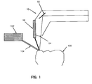
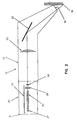
- the laser device 10 includes a handpiece 12 configured to be held by a user and further includes a laser source within a housing 20.
- One or more connectors are at the proximal end 8 of the laser device 10 ) for connecting the laser device 10 with an (not shown) electrical cable connection to a (not shown) cooling system.
- the connecting parts can be accommodated in the power supply.
- the laser source consists of a flash lamp 22, a laser rod 24, a Q switch 26 and laser mirrors 27 and 28.
- One or more flash lamps 22 serve as pumps for the laser light source.
- the flash lamp 22 is arranged in the longitudinal direction parallel to the central axis of the radiation head 12 and produces very short, intense flashes of light, approximately 1 to 100 pulses per second.
- the laser rod 24 is arranged in the longitudinal direction along the central axis of the radiation head 12 and parallel to the housing 20.
- the laser source in the housing 20 has at least two mirrors 27 and 28.
- the first mirror 27 of the laser is designed to be totally reflective and the second mirror 28 of the laser source 22 is designed to be partially reflective.
- a Q switch can be provided be.
- the Q switch is used to generate high beam intensities from the laser source. The radiation outbreaks are achieved by blocking the beam path to the second mirror 28 for a certain time interval during which the laser rod is being pumped, as a result of which the rod stores energy.
- the Q switch then creates the beam path to the mirror in a very short time and a gigantic pulse is generated in this way.
- the laser rod 24 can be made of one of the following materials: Er: YAG, Nd: YAG, Ho: YAG, CTE: YAG, ErCr: YSGG. 2 and 2a, the laser bars are Er: YAG.
- Er: YAG laser it is preferred to pulse the laser radiation to remove material.
- Each pulse of laser radiation has an energy of 50 milli-joules to 500 milli-joules.
- the frequency of the necessary pulses is between 5 and 50 Hertz.
- the pulse width must be between 0.1 micro-seconds and 300 micro-seconds.
- the laser energy per pulse is between 10 milli-joules and 400 milli-joules.
- the pulse width must be between 10 and 50 nano-seconds when operated with a Q-switch and between 1 and 300 micro-seconds when operated without a Q-switch.
- An Er: YAG laser rod is used in the laser device for dental applications according to FIG. 2, in particular because it emits light in the range of approximately 2.94 micrometers.
- the radiation emitted by the Er: YAG laser thus lies in a main absorption band of water.
- the Er: YAG laser radiation has low energy. It is also a wavelength that is easily absorbed by materials found in the body, such as hydrocarbons and water. If laser radiation hits hard surfaces, such as teeth, the surface must be cooled.
- the radiation generated in the laser source 20 passes when it passes through the second 2A and 2B pass through the mirror 28 and into the radiation head 12.
- the laser radiation enters the radiation head 12 in the longitudinal direction and is focused by a non-flexible light guide, a focusing lens 50.
- a light horn or a cylindrical rod can be used as a non-flexible light guide instead of the focusing lens 50.
- the deflecting mirror 52 is mounted obliquely within the radiation head.
- the deflecting mirror 52 serves to deflect the laser beams at any angle to the longitudinal direction.
- the angle between the optical axis of the radiation head 12 and the normal to the mirror 52 is approximately in the range between 30 and 60 degrees. The deflection of the laser beam allows the surgeon to reach all points on the surface to be treated.
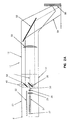
- FIGS. 2 and 2A alternative embodiments of the laser device 10 are shown.
- the embodiment according to FIG. 2B uses a concave mirror 52a as the focusing device instead of the focal lens 50 and the deflecting mirror 52, as is shown in FIGS. 2 and 2A.
- the concave mirror 52a fulfills both the function of focusing and deflecting the laser beam by a desired angle.
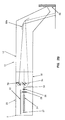
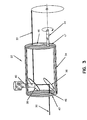
- the beam rotator 32 is arranged between the laser source 20 and the radiation head 12 as shown in FIGS. 2A and 2B. 3, the beam rotator comprises an adjusting device 40, first and second mirrors 36 and 38 and a housing 34.
- the beam rotator 32 is arranged along the longitudinal axis of the radiation head 12 and along the direction of propagation of the laser beam. It allows one at a first end 42 of the jet rotator 32 Opening 45 of the laser radiation 30 coming from the laser source to be incident.
- the opening 45 is arranged in the axis 44 of the beam rotator 32, which coincides with the axis of the laser beam 30.
- the laser radiation incident in the beam rotator 32 through the opening 45 is deflected by 90 degrees by the first mirror 36 and then again deflected by 90 degrees by the second mirror 38 so that its now propagation direction is parallel to the axis of the laser beam, but by a desired amount offset, runs.
- the beam rotator 32 has a second opening 46 at its second end 47, which allows the laser radiation to emerge from it.
- the jet rotator 32 also has a motor (not shown) together with an associated suitable gear (not shown) by means of which the jet rotator 32 is set in rotation about its axis of rotation.
- the laser radiation 30 emerging from the beam rotator 32 and traveling through the radiation head 12 describes a circle or a spiral on the radiation side of the handpiece 12.
- the circle or the spiral drills a cylindrical bore into the surface hit by the rotating laser radiation.
- the circumference of the circle or the spiral formed by the rotation of the jet rotator 32 can be enlarged or reduced, by rotating the second mirror 38 or by increasing or reducing the distance between the first and the second mirror 36 and 38.
- the adjuster 40 is a cylindrical rod with a head at its first end.
- the second mirror 38 is arranged at the second end of the adjusting device 40.
- the normal to the second mirror 38 includes a 45 degree angle with the axis of the adjustment device 40.
- the adjusting device 40 extends through an opening in the radiation head 12 and is displaceable or by means of a thread with the Walls of the radiation head 12 connected to allow the distance between the first and second mirrors 36 and 38 to be increased or decreased.
- the ability to drill holes of this size can be used to gain access through gums, to abscesses outside or inside teeth.
- the hole can be used to drain the abscess or inject medication to the infected site.
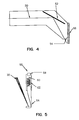
- the front end of the radiation head 12 is the end at which the mirror 52 is arranged.
- the mirror 52 deflects the radiation traveling through the radiation head 12 and out of the radiation head side 54.
- the direction of the radiation emerging from the side 54 of the radiation head can be controlled by moving the mirror 52.
- the radiation head 12 In order to maintain the correct focus during the operation of the laser device, it is necessary to keep the radiation head 12 at a constant distance from the tooth with a tolerance of the order of less than 1 millimeter. Since the laser radiation is focused on a point, it is important to ensure that this point is held on the surface that needs the laser effect.
- the radiation generated by laser rod 24, which is used in the present invention is in most cases in the infrared range and is therefore invisible. It is therefore not possible to focus the laser radiation by observation. Focusing could be done by superimposing visible laser radiation on the infrared laser beam. Although this is a common practice, it is not very suitable for the present application. Haze and steam rise from the laser impact point and make any visual observation questionable.
- the invention therefore proposes the use of mechanical sensor devices.
- the focus sensor 56 shown in Figs. 4 and 5, enables the laser device for dental use to operate as an attachable device, the laser being positioned by the part of the radiation field required for the removal of Dental material is most effective when projected onto the surface or into the cavity of the tooth. This is achieved in that the handpiece is pressed onto the surface to be treated until the contact 58 closes.
- the focus sensor thus represents a control device for the laser device, which enables the radiation of laser radiation only when the focus is reached.
- the focus sensor comprises a sensor 64 which is connected to a spring 62 and a button 60 and is provided in a housing 66 with a contact 58 which is arranged at the closed end of the housing 66.
- the spring 62 is connected at one end to the side walls of the housing. Therefore, when the handpiece 12 is pressed down against the surface to be treated, the spring 62 is compressed and the pin 60 moves up until it contacts the contact 58.
- the pin 60 touches the contact 58, the user receives an electrical signal that the correct focus has been achieved.
- the signal can be an optical or acoustic signal or an indicator on an interrupter that prevents the laser from being operated as long as the correct focus has not yet been reached. It must be stated that acceptable focusing can be given over a certain range of laser beam strength. This range depends on the focal length of the focusing lenses and the original beam diameter.
- the contact 58 shown in FIG. 5 can therefore be a sliding contact, which remains closed over the entire acceptable focusing range.
- a treatment station is provided with three sensor cushions 106, 108 and 110, the patient is asked to put his face against these cushions. The patient is not physically bound to these sensor pillows, but only leans on at will.
- the sensor pads include sensors that are electrically connected to the laser device 10. When the patient moves, the laser radiation is automatically switched off.
- the sensors inside the sensor cushions can react to a variety of different external variables such as pressure, movement or heat. It is clear that the sensitivity of the sensor pads is not limited to these sizes.
- sensor cushion sensitivity is intended to include sensitivity to any change outside of the cushion with respect to the patient's movement with respect to the sensor cushion.
- the dental laser handpiece preferably comprises a fixing device which, as shown in FIG. 7, is attached to the head of the handpiece.
- the fixing device helps to keep the laser radiation focused in the desired way.
- the fixing device comprises first and second clamping arms 70 and 72, which are articulated on a base 78 by means of spring-loaded joints 80 and 82, the base 78 being suitably attached to the radiation head 12.
- the spring-loaded joints 80 and 82 of clamp arms 70 and 72 give up hold on tooth 100 when the patient's movement becomes excessive.
- the second clamping arm 72 also has a fixing device 74, 76 which is mounted in a thread such that it can clamp the clamping arm 72 firmly to the tooth 100.
- Each clamp arm 70 and 72 also has position heads (not shown) which are provided at the end of each clamp arm and through which the clamp arms 70 and 72 are connected to the surface.
- each clamping arm 70 or 72 Before the clamping arms 70 and 72 are placed on the tooth 100 to be treated, the tooth 100 and its two neighboring teeth are preferably covered with a fast-curing plastic material. When this material is applied, care should be taken to ensure that a smooth surface is obtained.
- the position head of each clamping arm 70 or 72 has a locating pin (not shown) which is stamped into the plastic material. Therefore, if the clamp arms 70 or 72 are removed for any reason, they can be returned exactly to their original position by inserting the position pins of the position heads into the holes of the rapidly curing plastic material originally created by the position pins.
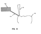
- Fig. 8 shows the cooling device of the system which is preferably used in connection with the laser device.
- the cooling device is electrically connected to the dental laser handpiece 10 and allows the application of a predetermined amount of a non-aqueous fluid in a selected area of the surface which is hit by laser radiation.
- the non-aqueous fluid that can be used in conjunction with an Er: YAG laser beam should be transparent, contain no water and have a low boiling point. Solutions that can be used include ethyl alcohol, benzyl acetate, furfury acetate or another organic solvent, that is harmless to the patient.
- the low boiling point of the non-aqueous fluid is very important because the latent heat (heat of vaporization) can be used to cool the tooth. The latent heat also allows the tooth to dry itself as a result of fluid evaporation.
- the cooling device includes a pulsator 102 which controls the dispensing of the non-aqueous solution.
- the pulsator is electrically connected to the dental laser handpiece so that the pulses of the non-aqueous solution are delivered between the pulses of the laser radiation.
- the non-aqueous solution is dispensed by means of a capillary tube 104 which has an opening which is arranged near the point of incidence of the laser radiation, as can be seen from FIG. 8.
- a well-measured amount of the non-aqueous solution is applied to the point of impact between each of the pulses.
- the size of the area covered by the non-aqueous solution should be similar to the point of impact of the laser radiation.
- the laser radiation can penetrate the non-aqueous solution with minimal absorption. However, all the heat that forms on the tooth surface due to the interaction between the laser radiation and the tooth surface is absorbed by the non-aqueous solution, and this is evaporated before the heat can penetrate the tooth.
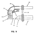
- FIG. 9 shows a dental laser system according to the invention, in which a clamping mechanism is used, which is connected to the radiation head 12 via a holder 84. Both the laser device 10 and the radiation head 12 are connected to the fixing mechanism via the holder 84.
- a simple cylindrical tube replaces the radiation head 12 as shown in Fig. 7.
- the holder 84 holds the dental laser device 10 and the radiation head 12 in an area which makes it possible for the gums to penetrate.
- the bracket 84 can be used in conjunction with the laser device 10 to perform a new and improved microsurgical operation that provides access to the root of an infected tooth.
- the infected area can be reached by the usual procedure in which a hole is made from the top of the tooth down into the infected area.
- the infected area can also be reached by drilling a hole from the side through the gums and jawbone.
- the infected area of the tooth is irradiated with laser radiation, which was from the radiation head 12 of the laser device 10.
- the method consists in positioning the front side 54 of the radiation head of the laser device 10 in the region of the infected area of the tooth such that the focal point of the laser radiation which is emitted by the laser device is directed at the infected area of the tooth.
- the dental laser device is then fixed in such a way that the front side 54 of the radiation head of the laser device keeps the focal point of the laser radiation permanently directed at the infected area of the tooth.
- the laser radiation is directed through the patient's gums and jawbone and drills a small hole through these materials before it reaches the infected area of the tooth.
- the abscess or wound is drained through the small hole. The infected area is then treated by injecting antibiotics into the small hole.
- the optimal size of the small hole created by the gums and jawbone by the laser radiation is between 0.2 and 1 millimeter. Although it is also possible to drill larger holes, the described method typically creates small holes in the range from 0.2 to 1 millimeter. Holes larger than 1 millimeter tend to take a long time to heal.
- the laser device 10 is fixed to the jaw by means of the clamps 70, 72 and positioned so that the laser beam 30 can penetrate the gum 86 and the jaw bone (not shown) in order to avoid the abscess in the tooth root of the tooth to edit the focus.
- the positioning of the laser device 10 is determined by the location of the infected area within the tooth. The location of the infected area is determined beforehand by an x-ray.
- the dental laser device is removed and the contents of the abscess are removed by applying a vacuum through the drilled canal. Medicines can be introduced through the canal by applying a slight positive pressure.
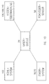
- the entire system according to the invention has a plurality of elements, which are all electrically connected to one another.
- the laser source 24 is electrically connected to the focus sensor 56, the fixation system 70, 72, the cooling system 102, the cushion sensors 106, 108, 110 and in some embodiments to the beam displacer 32.
- the focus sensor 56 is electrically connected to the laser source 24 in order to form an additional control and control means for the emission of the laser radiation that only allows laser beams to be emitted if the radiation head of the dental laser device is at a suitable focusing distance.
- the fixing system 70, 72 is electrically connected to the laser source and thus acts as a control when the laser radiation is emitted.
- the fixing system 70, 72 also acts as a stabilizer for the radiation head and stops the emission of the laser radiation when the laser head is subjected to excessive movement.
- the cushion sensors 106, 108, 110 also act as control mechanisms through their connection to the laser source and stop delivering laser radiation if the patient moves too much.
- the cooling system 102 is electrically connected to the laser source because the laser source and the cooling system must be synchronized to allow a predetermined amount of non-aqueous coolant solution to be applied between the pulses of the laser radiation.
Abstract
Description
Die vorliegende Erfindung betrifft im allgemeinen Lasersysteme zur Verwendung in der Medizin und im speziellen Laservorrichtungen und Verfahren, die zur Anwendung in der Dentalmedizin geeignet sind, wie bei der Behandlung von Abszessen, von kariösen Bereichen und auch beim Schneiden oder Entfernen von hartem oder weichem Gewebe.The present invention relates in general to laser systems for use in medicine and in particular to laser devices and methods which are suitable for use in dental medicine, such as in the treatment of abscesses, carious areas and also when cutting or removing hard or soft tissue.
Laserstrahlung wird derzeit in der Medizin und in der Dentalmedizin für die Durchführung zahlreicher Verfahren verwendet, inklusive Verfahren, die das Schneiden oder Verdampfen weichen Gewebes einschließlich Zahnfleisch, Nervengewebe und Zahnpulpa umfassen. Es wurde auch gezeigt, daß Laserstrahlung mit passender Wellenlänge und Energiedichte hartes Gewebe einschließlich Knochen, Zahnschmelz, Zahnbein und Zahnfüllungen ebenso gut schneiden kann, wie entmineralisierte harte Gewebe, wie beispielsweise kariöses Zahngewebe. Laserstrahlung kann auch zum Schneiden von Zahnstein, weichem oder hartem Zahnbelag und den meisten Materialien, die sich an Zahnoberflächen ausbilden, ebenso wie für ähnliche Materialien, die sich in Körperkanälen ausbilden, einschließlich Blutgefäßen und harnleitenden Gefäßen verwendet werden.Laser radiation is currently used in medicine and dental medicine to perform a variety of procedures, including procedures that involve cutting or vaporizing soft tissue including gums, nerve tissue, and tooth pulp. It has also been shown that laser radiation of the appropriate wavelength and energy density can cut hard tissue including bone, tooth enamel, dentin and dental fillings as well as demineralized hard tissues such as carious tooth tissue. Laser radiation can also be used to cut tartar, soft or hard plaque, and most materials that form on tooth surfaces, as well as similar materials that form in body channels, including blood vessels and urinary vessels.
Die Wirksamkeit von Laserstrahlung auf ein spezielles Gewebe hängt in großem Ausmaß von der Wellenlänge und der Intensität der Strahlung und der Form, in der die Strahlung dem Gewebe zugeführt wird, ab. Typischerweise wird die Strahlung auf eine von zwei Arten zugeführt, nämlich entweder als kontinuierliche Welle oder als pulsierende Welle. Die Art des für ein spezielles Anwendungsgebiet zu verwendenden Lasers wird durch die Intensität und Wellenlänge des Laserlichtes, das für diese Prozedur die größte Effektivität aufweist, bestimmt. Wenn pulsierende Strahlung für das Verfahren bevorzugt ist, müssen auch die optimalen Werte für die Pulsdauer und die Wiederholungsfrequenz bestimmt werden. Die Energie, die durch jeden Puls zugeführt wird, ist das Produkt der Laserstärke und der Pulsdauer. Die Energiedichte, mit der jeder Puls auf das zu behandelnde Gewebe aufgebracht wird, ist die gesamte übertragene Energie dividiert durch die Größe der Bestrahlungsfläche am Gewebe. Die Energiedichte ist ein wichtiger Parameter bei der Bestimmung der Wirkung der Laserstrahlung.The effectiveness of laser radiation on a particular tissue largely depends on the wavelength and intensity of the radiation and the form in which the radiation is delivered to the tissue. Typically, the radiation is delivered in one of two ways, either as a continuous wave or as a pulsating wave. The type of laser to be used for a specific application is determined by the intensity and wavelength of the laser light, which has the greatest effectiveness for this procedure. If pulsed radiation is preferred for the process, then the optimal values for the pulse duration and the repetition frequency can be determined. The energy delivered by each pulse is the product of the laser strength and the pulse duration. The energy density with which each pulse is applied to the tissue to be treated is the total energy transferred divided by the size of the irradiation area on the tissue. The energy density is an important parameter when determining the effect of laser radiation.
Bei Verfahren der oben beschriebenen Art ist die Möglichkeit, die Strahlung dem gewünschten Ort zuzuführen, von substantieller Bedeutung. Bei vielen Anwendungen ist es wünschenswert, die Strahlung mittels Handstücken, die durch einen Arzt oder Zahnarzt leicht gehandhabt werden können, zuzuführen. Da jedoch die Laser selbst, insbesondere die, die bei solchen medizinischen Behandlungen notwendigen Energieneveaus erreichen, relativ voluminöse Vorrichtungen sind, werden Handstücke in Verbindung mit optischen Leitern verwendet, die die Laserstrahlung vom Laser selbst zum Handstück leiten. Eines der Probleme die im Zusammenhang mit der Verwendung optischer Fasern für die Übertragung von Laserstrahlen auftreten, ist, daß bei bestimmten Wellenlängen der Laserstrahlen das für das Faserkabel zu verwendende Material spröde sein kann und dadurch zum Brechen neigt. Zusätzlich wird die Kohärenz der Laserstrahlung durch den Durchgang durch eine Faser verschlechtert.With methods of the type described above, the possibility of delivering the radiation to the desired location is of substantial importance. In many applications, it is desirable to deliver the radiation using handpieces that can be easily handled by a doctor or dentist. However, since the lasers themselves, particularly those that achieve energy levels required in such medical treatments, are relatively bulky devices, handpieces are used in conjunction with optical conductors that direct the laser radiation from the laser itself to the handpiece. One of the problems associated with the use of optical fibers for the transmission of laser beams is that, at certain wavelengths of the laser beams, the material to be used for the fiber cable can be brittle and therefore tends to break. In addition, the coherence of the laser radiation is deteriorated by the passage through a fiber.
Obwohl die Strahlung, die von vielen Lasern erzeugt wird, derzeit nicht zufriedenstellend durch optische Fasern übertragen werden kann, ist es bekannt, daß Strahlung mit einer Wellenlänge von etwa 0,5 Mikrometer bis zu etwa 1 Mikrometer über konventionelle optische Fasern übertragen werden kann. Bei längeren Wellenlängen gibt es Absorptionsbanden, insbesondere bei etwa 3 Mikrometer.Although the radiation generated by many lasers cannot currently be transmitted satisfactorily through optical fibers, it is known that radiation with a wavelength of about 0.5 microns to about 1 micron can be transmitted via conventional optical fibers. At longer wavelengths there are absorption bands, especially around 3 micrometers.
Andererseits haben in der Hand gehaltene Laser, die klein genug sind, um im Dentalbereich eingesetzt zu werden und die keine optischen Fasern verwenden, andere Probleme. Ohne optischer Faser muß der Chirurg den Brennpunkt der Laserstrahlung auf die zu behandelnde Stelle richten. Es wäre für einen Zahnchirurgen sehr schwierig, die präzise Lage und den präzisen Abstand mit ruhiger Hand einzuhalten. Es ist aber beides notwendig, um den Brennpunkt der Laserstrahlung im Zuge eines Eingriffes optimal zu führen. Die Schwierigkeit kann noch größer werden, da die Energie, die bei zahnärztlichen Lasern abgestrahlt wird, üblicherweise im Infrarot-Bereich liegt. Es wäre für einen Chirurgen extrem schwierig, den Brennpunkt von Laserstrahlen korrekt auf den zu behandelnden Punkt zu führen, wenn die Strahlen unsichtbar sind. Das Problem mit Infrarot-Laserstrahlung wurde in der Vergangenheit dadurch gelöst, daß die Handstücke so ausgerüstet worden sind, daß sichtbares Licht entlang der gleichen Achse und mit dem gleichen Brennpunkt, wie die Laserstrahlung, ausgesandt wird. Das sichtbare Licht erlaubt es dem Zahnarzt, das Dentalinstrument richtig zu richten, so daß der Brennpunkt der Laserstrahlung passend auf das Ziel gerichtet ist. Es löst aber natürlich das sichtbare Licht nicht die Probleme, die mit einer unruhigen Hand verbunden sind. Es ist somit Bedarf für ein dentales Lasersystem gegeben, bei dem keine optischen Fasern verwendet werden und das bezüglich der durch die Laserstrahlung zu bearbeitenden Oberfläche eine konstante Lage und einen konstanten Abstand einhält.On the other hand, hand-held lasers that are small enough to be used in the dental field and that do not use optical fibers have other problems. Without optical fiber, the surgeon must focus the laser radiation on the area to be treated. It would be very difficult for a dental surgeon to maintain the precise location and distance with a steady hand. However, both are necessary in order to optimally guide the focal point of the laser radiation in the course of an intervention. The difficulty can be even greater, since the energy that is emitted by dental lasers is usually in the infrared range. It would be extremely difficult for a surgeon to correctly direct the focus of laser beams to the point to be treated if the beams are invisible. The problem with infrared laser radiation has been solved in the past by equipping the handpieces in such a way that visible light is emitted along the same axis and with the same focal point as the laser radiation. The visible light allows the dentist to properly direct the dental instrument so that the focal point of the laser radiation is aimed at the target. Of course, visible light does not solve the problems associated with a restless hand. There is therefore a need for a dental laser system in which no optical fibers are used and which maintains a constant position and a constant distance with respect to the surface to be processed by the laser radiation.
Laserstrahlung mit einer Wellenlänge von unter 3 Mikrometer, inkludiert die die durch die Nd:YAG Laser (fundamentale Wellenlänge 1,06 Mikrometer) und die Er:YAG Laser (fundamentale Wellenlänge 2,94 Mikrometer) erzeugt werden. Beide dieser Laserstrahlformen sind in der Lage, verschiedene Arten von Gewebe zu schneiden, obwohl jede dieser beiden Typen es auf etwas andere Weise tut. Die Unterschiede resultieren teilweise daher, daß Wasser einen sehr geringen Absoprtionskoeffizienten für Laserstrahlung mit einer Wellenlänge von 1,06 Mikrometer und einen relativ großen Absorptionskoeffizienten für Strahlung bei der Wellenlänge von 2,94 Mikrometer aufweist. Es ist im Stand der Technik bekannt, daß passende Laser für dentale Anwendungen die Er:YAG und in geringerem Umfang die Nd:YAG-Laser sind. Der Grund dafür ist, daß die Er:YAG-Strahlung mit einer Hauptabsorptionsbande von Wasser zusammenfällt.Laser radiation with a wavelength of less than 3 microns includes those generated by the Nd: YAG lasers (fundamental wavelength 1.06 microns) and the Er: YAG lasers (fundamental wavelength 2.94 microns). Both of these laser beam shapes are able to cut different types of tissue, although each of these two types does it in a slightly different way. The differences result partly from the fact that water is one has a very low absorption coefficient for laser radiation with a wavelength of 1.06 micrometers and a relatively large absorption coefficient for radiation at the wavelength of 2.94 micrometers. It is known in the prior art that suitable lasers for dental applications are the Er: YAG and to a lesser extent the Nd: YAG lasers. The reason for this is that the Er: YAG radiation coincides with a main absorption band of water.
Erbium (Er) ist ein chemisches Element der Selten-Erde-Gruppe, das mit Yttrium auftritt und auch als Quelle für Laserstrahlung verwendet wird. Die Er:YAG-Laser sind gepulste Festkörperlaser mit einer maximalen Emission im mittleren Infrarotbereich bei 2,94 Mikrometer, in dem Wasser stark absorbiert. Laserchirurgie, die mit Er:YAG-Lasern durchgeführt wird, führt dazu, daß Wasser im angestrahlten Gewebe die Strahlungsenergie aufnimmt.Erbium (Er) is a chemical element of the rare earth group that occurs with yttrium and is also used as a source of laser radiation. The Er: YAG lasers are pulsed solid-state lasers with a maximum emission in the middle infrared range at 2.94 micrometers, in which water is strongly absorbed. Laser surgery, which is performed with Er: YAG lasers, causes water in the illuminated tissue to absorb the radiation energy.
Harte Oberflächen, wie Zähne, werden, obwohl sie nur sehr wenig Wasser enthalten, auch durch Absorption der Laserstrahlung erhitzt. Wenn Laserstrahlung einem Zahn zugeführt wird, wird, um eine Beschädigung der Pulpe, die ein lebendes Gewebe ist, zu vermeiden, der Zahn simultan zur Laserbestrahlung gekühlt. In der Vergangenheit wurde ein Wasserspray, ein Luftspray oder eine Kombination der beiden verwendet, um harte Oberflächen, wie sie Zähne aufweisen, zu kühlen.Hard surfaces such as teeth, although they contain very little water, are also heated by absorption of the laser radiation. When laser radiation is applied to a tooth, in order to avoid damage to the pulp, which is a living tissue, the tooth is cooled simultaneously with the laser radiation. In the past, a water spray, an air spray, or a combination of the two was used to cool hard surfaces such as teeth.
In der konventionellen dentalen Chirurgie und in der dentalen Laser-Chirurgie wurde Wasserspray als Kühlmittel für die Oberfläche nach einem Strahlungspuls verwendet. Das US-Patent 4,940,411 von Vassiliadis et al. offenbart einen Dental-Laser, der einen Nd:YAG-Laser verwendet. In diesem Patent wird Wasser nach einem Laserpuls auf den Zahn gesprüht, gefolgt vom Trocknen des Zahns vor der nächsten Aktivierung des pulsierenden Lasers.In conventional dental surgery and in dental laser surgery, water spray was used as a coolant for the surface after a radiation pulse. U.S. Patent 4,940,411 to Vassiliadis et al. discloses a dental laser using an Nd: YAG laser. In this patent, water is sprayed onto the tooth after a laser pulse, followed by drying the tooth before the next activation of the pulsing laser.
Andere Verfahren zur Kühlung wurden durch die Verwendung der kontrollierten Zugabe von Wasser statt des Trocknens der Oberfläche vor und/oder während der Laserbehandlung erreicht, so daß während der Behandlung nur ein dünner Wasserfilm vorhanden ist. Die Wirkung des Aufsprühens von Wasser, um einen dünnen Film zu erzielen, ist darauf gerichtet, eine merkliche Erhöhung der Laserwirksamkeit und eine geringere Beschädigung als mit den früheren Methoden der Laserbehandlung harter Materialien zu erreichen. Es ist jedoch das Aufsprühen von Wasser kontraproduktiv bei harten Oberflächen, da Wasser die Er:YAG-Laserstrahlung deutlich absorbiert, wenn das Wasser auf der Oberfläche eine Dicke von über einigen wenigen Mikrometern aufweist. Bei harten Materialien, beispielsweise Zähnen, die eine ungleichmäßige Oberfläche haben, die deutliche Einbuchtungen aufweist, akkumuliert das Wasser in Taschen, die größer bzw. tiefer als einige wenige Mikrometer sind. Der Effekt solcher Ansammlungen minimiert die Wirksamkeit der Laserstrahlung auf die Oberfläche, die durch die Wassertasche abgedeckt ist, da eben das Wasser die Laserstrahlung absorbiert.Other methods of cooling have been achieved by using the controlled addition of water instead of drying the surface before and / or during the laser treatment so that only a thin film of water is present during the treatment. The effect of spraying water to achieve a thin film is directed to achieving a marked increase in laser efficiency and less damage than with the previous methods of laser treatment of hard materials. However, spraying water is counterproductive on hard surfaces, since water clearly absorbs the Er: YAG laser radiation if the water has a thickness of more than a few micrometers on the surface. In the case of hard materials, for example teeth that have an uneven surface that has distinct indentations, the water accumulates in pockets that are larger or deeper than a few micrometers. The effect of such accumulations minimizes the effectiveness of the laser radiation on the surface covered by the water pocket, because the water absorbs the laser radiation.
Das Kühlen harter Oberflächen mit Luft ist ebenfalls kontraproduktiv, da die Luft die Bildung von thermischen Gradienten im Zahn begünstigt, was die Ausbildung von Sprüngen im Zahn bewirken kann. Es besteht ein Bedarf für ein Verfahren des Kühlens einer harten Oberfläche, beispielsweise von Zähnen, das eine gleichmäßige Kühlung ungleichmäßiger Oberflächen bewirkt, ohne daß die oben beschriebenen Nachteile auftreten.Cooling hard surfaces with air is also counterproductive because the air favors the formation of thermal gradients in the tooth, which can cause cracks to form in the tooth. There is a need for a method of cooling a hard surface, such as teeth, that provides uniform cooling of uneven surfaces without the disadvantages described above.
Dentale Vorrichtungen werden bekannterweise bei der Durchführung chirurgischer Eingriffe verwendet, beispielweise bei der Wurzelkanalbehandlung, um Zugang zu den infizierten Teilen eines Zahnes zu erhalten. Eine Wurzelkanalbehandlung ist ein chirurgischer Eingriff, der durchgeführt wird, wenn ein Zahn durch eine Verwundung oder einen Abszeß beeinträchtigt ist. Das infizierte Gebiet liegt fast immer nahe der Wurzel des Zahnes und kann innerhalb oder außerhalb der Zahnwurzel liegen. Es ist ein bekanntes Vorgehen, einen Kanal vom Kopf des Zahns in die Wurzel zu bohren, um Zugang zum infizierten Gebiet zu erhalten. Der Inhalt der Wurzel (Nerven und Blutgefäße) wird entfernt (das bedeutet, daß der Zahn abstirbt) und die medikamentöse Behandlung erfolgt durch den Kanal. Nach der Behandlung wird der Kanal mit passendem Material gefüllt.Dental devices are known to be used in performing surgical procedures, such as root canal treatment, to gain access to the infected parts of a tooth. Root canal treatment is a surgical procedure that is performed when a tooth is injured or a tooth is damaged Abscess is impaired. The infected area is almost always near the root of the tooth and can be inside or outside the tooth root. It is a known practice to drill a canal from the head of the tooth into the root to gain access to the infected area. The contents of the root (nerves and blood vessels) are removed (which means that the tooth dies) and medication is given through the canal. After the treatment, the canal is filled with suitable material.
Es ist auch möglich, eine Wurzelkanalbehandlung so durchzuführen, daß ein Teil des Zahnfleischgewebes ebenso wie ein Teil des Kieferknochens entfernt wird, um Zugang zur Wurzel des infizierten Zahns zu erhalten. Es werden dann Abszesse entfernt, das Knochengewebe wird mit Zahnfleischgewebe bedeckt und der Heilungsprozeß benötigt einige Zeit, abhängig von der Größe des Lochs im Kieferknochen. Es ist schwer, kleine Löcher zu bohren, wenn das vom Bohrer erfaßte Gewebe sowohl hart als auch weich ist. Es besteht ein Bedarf für ein Behandlungssystem, das den Zugang zum infizierten Bereich eines Zahnes durch kleinere Löcher als bisher zur Verfügung stellt. Kleinere Löcher würden die Dauer des Heilungsprozesses, der auf diesen Eingriff folgt, drastisch reduzieren.It is also possible to carry out a root canal treatment in such a way that part of the gum tissue as well as part of the jawbone is removed in order to gain access to the root of the infected tooth. Then abscesses are removed, the bone tissue is covered with gum tissue and the healing process takes some time, depending on the size of the hole in the jawbone. It is difficult to drill small holes when the tissue gripped by the drill is both hard and soft. There is a need for a treatment system that provides access to the infected area of a tooth through smaller holes than before. Smaller holes would drastically reduce the duration of the healing process that follows this procedure.
Die vorliegende Erfindung betrifft ein Lasersystem zur Verwendung in der Dentalmedizin und umfaßt einen Laser, der aus einer Laserquelle in einem Gehäuse besteht, einen am Gehäuse angebrachten Abstrahlkopf, der Laserstrahlung von der Laserquelle erhält und weiterleitet und ein Fokussiermittel, das am Abstrahlkopf angebracht ist, um den Abstrahlkopf in bestmöglichem Abstand von der durch die Laserstrahlung zu behandelnde Oberfläche zu positionieren. Die Laservorrichtung kann auch ein Fixiersystem umfassen, das am Abstrahlkopf angeordnet ist, um die Laservorrichtung während der Behandlung in ihrer Position zu halten.The present invention relates to a laser system for use in dental medicine and comprises a laser consisting of a laser source in a housing, a radiation head attached to the housing which receives and transmits laser radiation from the laser source and a focusing means which is attached to the radiation head to position the radiation head at the best possible distance from the surface to be treated by the laser radiation. The laser device can also comprise a fixing system which is arranged on the radiation head in order to hold the laser device in position during the treatment.
Die vorliegende Erfindung umfaßt auch einen Strahlendreher, wobei der Abstrahlkopf der Laservorrichtung den Strahlendreher aufweist, der einen zentralen Spiegel und einen verschieblich adjustierbaren äußeren Spiegel innerhalb eines drehbaren Gehäuses aufweist. Der Strahlendreher ist an einem ersten Ende des Abstrahlkopfes so angeordnet, daß er die von der Laserquelle kommende Laserstrahlung verdreht. Der verschieblich adjustierbare äußere Spiegel wird verwendet, um die Größe des durch den drehenden Laserstrahl zu bohrenden Loches zu vergrößern oder zu verkleinern.The present invention also includes a beam driver, wherein the radiation head of the laser device comprises the beam driver having a central mirror and a slidably adjustable outer mirror within a rotatable housing. The beam rotator is arranged at a first end of the radiation head in such a way that it rotates the laser radiation coming from the laser source. The slidably adjustable outer mirror is used to increase or decrease the size of the hole to be drilled by the rotating laser beam.
Die erfindungsgemäße Laservorrichtung kann mit einem Kühlsystem versehen sein. Das Kühlsystem wird elektromechanisch durch die Laserquelle des Lasers gesteuert und weist Mittel zur Kühlung der durch die Laserstrahlung getroffenen Oberfläche auf. Das Kühlsystem sprüht zwischen den Pulsen der Laserstrahlung eine nicht-wässerige Lösung auf die zu kühlende Oberfläche.The laser device according to the invention can be provided with a cooling system. The cooling system is controlled electromechanically by the laser source of the laser and has means for cooling the surface hit by the laser radiation. The cooling system sprays a non-aqueous solution between the pulses of the laser radiation onto the surface to be cooled.
Der Fokussensor der vorliegenden Erfindung ermöglicht die Positionierung der Laservorrichtung nahe der durch die Laserstrahlung zu bearbeitenden Oberfläche, so daß der Brennpunkt der Laserstrahlung in der gewünschten Lage auf der zu bearbeitenden Oberfläche liegt. Die Blockiervorrichtung für die Laservorrichtung ermöglicht es, die Laservorrichtung vorübergehend in einer solchen Position zu fixieren, daß der Brennpunkt der Laserstrahlung unveränderlich auf dem ausgewählten Gebiet der zu bearbeitenden Oberfläche liegt.The focus sensor of the present invention enables the laser device to be positioned close to the surface to be processed by the laser radiation, so that the focal point of the laser radiation lies in the desired position on the surface to be processed. The blocking device for the laser device makes it possible to temporarily fix the laser device in a position such that the focal point of the laser radiation lies invariably on the selected area of the surface to be processed.
Die vorliegende Erfindung ermöglicht auch das Durchführen chirurgischer Eingriffe auf einer infizierten Oberfläche eines Zahnes unter Verwendung von Laserstrahlen, die von der Laservorrichtung kommen. Die Laservorrichtung wird so positioniert, daß ihr Abstrahlkopf eine solche Lage zum infizierten Zahn einnimmt, daß der Brennpunkt der Laserstrahlung auf das infizierte Gebiet des Zahnes fällt. Die Laserstrahlung, die durch das Zahnfleisch und den Kieferknochen des Patienten geleitet wird, um eine Öffnung im Zahnfleisch und im Kieferknochen zu bilden, erlauben es der Laserstrahlung, auf das infizierte Gebiet des Zahnes zu wirken. Während der Wirkungsdauer der Laserstrahlung wird der Kopf der Laservorrichtung so fixiert, daß der Brennpunkt der Laserstrahlung auf dem infizierten Gebiet des Zahnes durch das Zahnfleisch und den Kieferknochen festbleibt. Nachdem auf diese Weise Zugang zum infizierten Gebiet des Zahnes geschaffen wurde, wird das infizierte Gebiet dräniert und mit Medikamenten behandelt.The present invention also enables surgery to be performed on an infected surface of a tooth using laser beams coming from the laser device. The laser device is positioned so that its radiation head is positioned so that the focal point of the laser radiation to the infected tooth falls on the infected area of the tooth. The laser radiation that passes through the patient's gums and jawbone to form an opening in the gums and jawbone allows the laser radiation to act on the infected area of the tooth. During the period of action of the laser radiation, the head of the laser device is fixed in such a way that the focal point of the laser radiation remains fixed on the infected area of the tooth through the gums and jawbone. After accessing the infected area of the tooth in this way, the infected area is drained and treated with medication.
Die Erfindung wird im folgenden an Hand der Zeichnung näher erläutert. Dabei ist
- die Fig. 1 eine schematische Ansicht einer erfindungsgemäßen Vorrichtung, die eine Oberfläche gleichzeitig mit Laserstrahlung behandelt und mit einem Kühlmittel kühlt,
- die Fig. 2 ist ein Längsschnitt, der die wesentlichen Teile der erfindungsgemäßen Laservorrichtung zeigt, die Fig. 2A ist eine Ansicht ähnlich der Fig. 2, wobei die Vorrichtung einen Strahldreher aufweist,
- die Fig. 2B ist eine Ansicht ähnlich der Fig. 2A und zeigt eine erfindungsgemäße Variante der Vorrichtung,
- die Fig. 3 ist ein Längsschnitt, der die wesentlichen Teile eines erfindungsgemäßen Strahldrehers zeigt,
- die Fig. 4 ist ein schematischer Längsschnitt durch das Frontende einer erfindungsgemäßen Vorrichtung, bei der die Spiegelungsverhältnisse an einem Knick in der Vorrichtung deutlich werden,
- die Fig. 5 ist eine Seitenansicht, die die wesentlichen Bestandteile des erfindungsgemäßen Fokussensors darstellt,
- die Fig. 6 ist eine perspektivische Ansicht von Kopfauflagen zur Verwendung mit einem erfindungsgemäßen Lasersystems,
- die Fig. 7 ist ein Längsschnitt durch eine erfindungsgemäße an einem Zahn befestigte Fixiervorrichtung,
- die Fig. 8 ist eine perspektivische Ansicht eines erfindungsgemäßen Lasersystems mit Kühlvorrichtung, auf einen Zahn wirkend,
- die Fig. 9 ist ein Längsschnitt durch eine erfindungsgemäße an einem Zahn angreifende Fixiervorrichtung, die mit einem durch das Zahnfleisch und den Kieferknochen wirkenden Laser zusammenwirkt und
- die Fig. 10 ist ein Blockdiagramm einer erfindungsgemäßen Laservorrichtung, die die elektrischen Verbindungen zeigt.
- 1 is a schematic view of a device according to the invention, which simultaneously treats a surface with laser radiation and cools it with a coolant,
- FIG. 2 is a longitudinal section showing the essential parts of the laser device according to the invention; FIG. 2A is a view similar to FIG. 2, the device having a beam rotator,
- 2B is a view similar to FIG. 2A and shows a variant of the device according to the invention,
- 3 is a longitudinal section showing the essential parts of a jet rotator according to the invention,
- 4 is a schematic longitudinal section through the front end of a device according to the invention, in which the reflection conditions at a kink in the device become clear,
- 5 is a side view illustrating the essential components of the focus sensor according to the invention,
- 6 is a perspective view of headrests for use with a laser system in accordance with the invention;
- 7 is a longitudinal section through a fixing device according to the invention fastened to a tooth,
- 8 is a perspective view of a laser system according to the invention with a cooling device, acting on a tooth,
- 9 is a longitudinal section through a fixing device according to the invention, which acts on a tooth and which interacts with a laser acting through the gums and the jawbone and
- 10 is a block diagram of a laser device according to the invention, showing the electrical connections.
Gemäß dem Hauptkonzept der Erfindung umfaßt ein dentales Lasersystem eine Laservorrichtung, die es dem Benutzer erlaubt, Laserstrahlen an die gewünschte Stelle innerhalb des Mundes eines Patienten zu richten, ohne optische Fasern zu verwenden. Das Lasersystem umfaßt auch ein Kühlsystem, um die mit der Laserstrahlung der Laserquelle zu behandelnde Oberfläche zu kühlen. Die Laserstrahlung wird durch den Fokussiersensor der Laservorrichtung genau auf die gewünschte Stelle gerichtet und wird durch das Fixiersystem der Vorrichtung korrekt gerichtet gehalten. Da der Laserstrahl auf eine solche Weise fokussiert wird, daß der Brennpunkt des Laserstrahles auf die korrekte Stelle gerichtet ist und da diese Position durch ein Fixiersystem aufrecht erhalten wird, kann der Benutzer chirurgische Eingriffe mit größter Genauigkeit und kleinsten Fehlern durchzuführen. Das Kühlsystem der Laservorrichtung arbeitet simultan zur Laserbestrahlung und erlaubt es dem Benutzer, chirurgische Eingriffe in kürzester Zeit durchzuführen. Simultanes Kühlen reduziert die Notwendigkeit der Abschaltung des Lasers unter Unterbrechung der Laserbehandlung, um das Auskühlen harter Oberflächen, wie beispielsweise der Oberflächen von Zähnen, zu erlauben.According to the main concept of the invention, a dental laser system includes a laser device that allows the user to direct laser beams to the desired location within a patient's mouth without using optical fibers. The laser system also includes a cooling system to cool the surface to be treated with the laser radiation from the laser source. The laser radiation is directed exactly at the desired location by the focusing sensor of the laser device and is held correctly directed by the fixing system of the device. Since the laser beam is focused in such a way that the focal point of the laser beam is directed to the correct position and since this position is maintained by a fixing system, the user can carry out surgical interventions with the greatest accuracy and the smallest errors. The cooling system of the laser device works simultaneously with the laser radiation and allows the user to perform surgical interventions in the shortest possible time. Simultaneous cooling reduces the need to turn the laser off while interrupting the laser treatment to allow cooling of hard surfaces such as the surfaces of teeth.
Um die Auswirkungen kleiner, unvermeidlicher Vibrationen minimal zu halten, muß die Laservorrichtung nahe an der mit dem Laserstrahl zu behandelnden Oberfläche angeordnet werden. Die Nähe des Abstrahlkopfes zur zu behandelnden Oberfläche macht es notwendig, daß die Laservorrichtung und Laserquelle kompakt ist. Eine kompakte Laserquelle ist eine, die klein genug ist, um in ein dentales Handstück zu passen oder eine, die so ausgestaltet ist, daß der Abstrahlkopf der Laservorrichtung in eine Halterung nahe dem Gesicht des Patienten gelagert werden kann, ähnlich einer Röntgenröhre für zahnärztliche Zwecke.In order to minimize the effects of small, unavoidable vibrations, the laser device must be placed close to the surface to be treated with the laser beam. The proximity of the radiation head to the one to be treated Surface requires that the laser device and laser source be compact. A compact laser source is one that is small enough to fit in a dental handpiece or one that is designed so that the radiation head of the laser device can be placed in a holder near the patient's face, similar to an X-ray tube for dental purposes.
Die Fig. 1 und 2 zeigen eine Ausführungsform einer Laservorrichtung 10 eines dentalen Lasersystems, das erfindungsgemäß ausgebildet ist. Die Laservorrichtung 10 umfaßt ein Handstück 12, das so ausgebildet ist, daß es von einem Benutzer in der Hand gehalten werden kann und umfaßt weiters eine Laserquelle innerhalb eines Gehäuses 20. Am proximalen Ende 8 der Laservorrichtung 10 ist einer oder sind mehrere Verbindungsstücke (nicht dargestellt) zur Verbindung der Laservorrichtung 10 mit einer (nicht dargestellten) elektrischen Kabelverbindung zu einem (nicht dargestellten) Kühlsystem vorgesehen. Bei anderen Ausführungsformen können die Verbindungsteile in der Energieversorgung untergebracht werden.1 and 2 show an embodiment of a
Die Laserquelle besteht aus einer Blitzlampe 22, einem Laserstab 24, einem Q-Schalter 26 und Laserspiegel 27 und 28. Eine oder mehrere Blitzlampen 22 dienen als Pumpen für die Laserlichtquelle. Die Blitzlampe 22 ist in Längsrichtung parallel zur Zentralachse des Abstrahlkopfes 12 angeordnet und produziert sehr kurze, intensive Lichtblitze, etwa 1 bis 100 Pulse pro Sekunde.The laser source consists of a
Der Laserstab 24 ist in Längsrichtung entlang der Mittelachse des Abstrahlkopfes 12 und parallel zum Gehäuse 20 angeordnet. Die Laserquelle im Gehäuse 20 weist zumindest zwei Spiegel 27 und 28 auf. Der erste Spiegel 27 des Lasers ist totalreflektierend ausgebildet und der zweite Spiegel 28 der Laserquelle 22 ist teilweise reflektierend ausgebildet. Gegebenenfalls kann ein Q-Schalter vorgesehen sein. der Q-Schalter wird verwendet, um große Strahlenintensitäten der Laserquelle zu erzeugen. Die Strahlungsausbrüche werden erreicht, indem der Strahlengang zum zweiten Spiegel 28 für ein gewisses Zeitintervall, während dessen der Laserstab gepumpt wird, gesperrt ist, wodurch der Stab Energie speichert. Der Q-Schalter stellt dann in sehr kurzer Zeit den Strahlengang zum Spiegel her und ein gigantischer Puls wird so erzeugt.The
Der Laserstab 24 kann aus einem der folgenden Materialien bestehen: Er:YAG, Nd:YAG, Ho:YAG, CTE:YAG, ErCr:YSGG. In Fig. 2 und 2a gezeigten Ausführungsformen sind die Laserstäbe Er:YAG. Beim Verwenden eines Er:YAG-Lasers wird es bevorzugt zum Entfernen von Material die Laserstrahlung zu pulsen. Jeder Puls an Laserstrahlung hat eine Energie von 50 Milli-Joules bis 500 Milli-Joules. Die Frequenz der notwendigen Pulse liegt zwischen 5 und 50 Hertz. Die Pulsbreite muß zwischen 0,1 Mikro-Sekunden und 300 Mikro-Sekunden liegen. Alternativ dazu liegt bei Verwendung eines Nd:YAG Lasers die Laserenergie pro Puls zwischen 10 Milli-Joules und 400 Milli-Joules. Die Pulsbreite muß bei Betrieb mit Q-Schalter zwischen 10 und 50 Nano-Sekunden liegen und beim Betrieb ohne Q-Schalter zwischen 1 und 300 Mikro-Sekunden.The
Ein Er:YAG-Laserstab wird bei der Laservorrichtung für dentale Anwendungen gemäß Fig. 2, insbesondere deshalb verwendet, weil er Licht im Bereich von etwa 2,94 Mikrometer abstrahlt. Damit liegt die vom Er:YAG-Laser abgegebene Strahlung in einem Hauptabsorptionsband von Wasser. Die Er:YAG Laserstrahlung weist niedrige Energie auf. Es ist auch eine Wellenlänge, die von Materialien, die man im Körper findet, beispielsweise Kohlenwasserstoffen und Wasser, leicht absorbiert wird. Wenn Laserstrahlung auf harte Oberflächen, beispielsweise Zähne trifft, muß die getroffene Oberfläche gekühlt werden. Die in der Laserquelle 20 erzeugte Strahlung gelangt, wenn sie durch den zweiten Spiegel 28 hindurchgelangt, so wie in den Fig. 2A und 2B dargestellt, in den Strahldreher 32 und gelangt in den Abstrahlkopf 12. Die Laserstrahlung tritt in Längsrichtung in den Abstrahlkopf 12 ein und wird durch einen nicht flexiblen Lichtleiter, eine Fokussierlinse 50 gebündelt. Bei anderen Ausführungsformen kann ein Lichthorn oder ein zylindrischer Stab als nicht flexibler Lichtleiter statt der Fokussierlinse 50 verwendet werden.An Er: YAG laser rod is used in the laser device for dental applications according to FIG. 2, in particular because it emits light in the range of approximately 2.94 micrometers. The radiation emitted by the Er: YAG laser thus lies in a main absorption band of water. The Er: YAG laser radiation has low energy. It is also a wavelength that is easily absorbed by materials found in the body, such as hydrocarbons and water. If laser radiation hits hard surfaces, such as teeth, the surface must be cooled. The radiation generated in the
Nachdem die Laserstrahlung fokussiert wurde, trifft sie auf den Umlenkspiegel 52. Der Umlenkspiegel 52 ist schräg innerhalb des Abstrahlkopfes montiert. Der Umlenkspiegel 52 dient zur Umlenkung der Laserstrahlen in jedem beliebigen Winkel zur Längsrichtung. Der Winkel zwischen der optischen Achse des Abstrahlkopfes 12 und der Normalen auf den Spiegel 52 liegt etwa im Bereich zwischen 30 und 60 Grad. Die Umlenkung des Laserstrahles erlaubt es dem Chirurgen, alle Punkte auf der zu behandelnden Oberfläche zu erreichen.After the laser radiation has been focused, it strikes the deflecting
In den Fig. 2A und 2B sind alternative Ausführungsformen der Laservorrichtung 10 dargestellt. Die Ausführungsform nach Fig. 2B verwendet an Stelle der Brennlinse 50 und des Umlenkspiegels 52 einen konkaven Spiegel 52a als Fokussiervorrichtung, wie dies in den Fig. 2 und 2A dargestellt ist. Der konkave Spiegel 52a erfüllt sowohl die Funktion des Fokussierens als auch des Umlenkens des Laserstrahles um einen gewünschten Winkel.2A and 2B, alternative embodiments of the
Der Strahldreher 32 ist so, wie in Fig. 2A und 2B gezeigt, zwischen der Laserquelle 20 und dem Abstrahlkopf 12 angeordnet. Wie aus Fig. 3 ersichtlich, umfaßt der Strahldreher eine Adjustiervorrichtung 40, erste und zweite Spiegel 36 und 38 und ein Gehäuse 34. Der Strahldreher 32 ist entlang der Längsachse des Abstrahlkopfes 12 und entlang der Ausbreitungsrichtung des Laserstrahles angeordnet. An einem ersten Ende 42 des Strahldrehers 32 erlaubt es eine Öffnung 45 der Laserstrahlung 30, aus der Laserquelle kommend, einzufallen. Die Öffnung 45 ist in der Achse 44 des Strahldrehers 32 angeordnet, die mit der Achse des Laserstrahles 30 zusammenfällt. Die in den Strahldreher 32 durch die Öffnung 45 einfallende Laserstrahlung wird durch den ersten Spiegel 36 um 90 Grad abgelenkt und dann durch den zweiten Spiegel 38 wiederum um 90 Grad so abgelenkt, daß ihre nunmehrige Fortpflanzungsrichtung parallel zur Achse des Laserstrahles, aber um einen gewünschten Betrag dazu versetzt, verläuft. Der Strahldreher 32 weist eine zweite Öffnung 46 an seinem zweiten Ende 47 auf, die es der Laserstrahlung erlaubt, aus ihm auszutreten. Der Strahldreher 32 weist auch einen (nicht dargestellten) Motor samt zugehörigem passendem (nicht dargestellten) Getriebe auf, durch das der Strahldreher 32 um seine Drehachse in Rotation versetzt wird.The
Wenn der Strahldreher 32 um seine Achse gedreht wird, beschreibt die aus dem Strahldreher 32 austretende Laserstrahlung 30, die durch den Abstrahlkopf 12 wandert, einen Kreis oder eine Spirale an der Abstrahlseite des Handstückes 12. Der Kreis oder die Spirale bohrt eine zylindrische Bohrung in die durch die rotierende Laserstrahlung getroffene Oberfläche. Mit Hilfe einer Justiervorrichtung 40 kann der Umfang des Kreises oder der Spirale, die durch die Rotation des Strahldrehers 32 gebildet wird, vergrößert oder verkleinert werden, durch Verdrehung des zweiten Spiegels 38 oder durch Vergrößerung oder Verkleinerung des Abstandes zwischen dem ersten und dem zweiten Spiegel 36 und 38. Die Justiervorrichtung 40 ist ein zylindrischer Stab mit einem Kopf an seinem ersten Ende. Am zweiten Ende der Justiervorrichtung 40 ist der zweite Spiegel 38 angeordnet. Die Normale auf den zweiten Spiegel 38 schließt einen 45 Grad Winkel mit der Achse der Justiervorrichtung 40 ein. Die Justiervorrichtung 40 erstreckt sich durch eine Öffnung im Abstrahlkopf 12 und ist verschieblich oder mittels eines Gewindes mit den Wänden des Abstrahlkopfes 12 verbunden, um die Vergrößerung oder Verkleinerung des Abstandes zwischen dem ersten und dem zweiten Spiegel 36 und 38 zu erlauben.When the
Mit ordentlich eingestellter Fokussierung ist es möglich, Löcher zu bohren, die bei einem Durchmesser, der nicht größer ist als 200 Mikrometer, jede gewünschte Tiefe aufweisen. Die Möglichkeit, Löcher dieser Größe zu bohren, kann beispielsweise verwendet werden, um sich Zutritt durch Zahnfleisch, zu Abszessen außerhalb oder innerhalb von Zähnen zu verschaffen. Das Loch kann dazu verwendet werden, den Abszeß zu dränieren oder Medikamente zur infizierten Stelle zu injizieren.With properly adjusted focus, it is possible to drill holes that have any desired depth with a diameter that is no greater than 200 microns. For example, the ability to drill holes of this size can be used to gain access through gums, to abscesses outside or inside teeth. The hole can be used to drain the abscess or inject medication to the infected site.
Fig. 4 zeigt das Frontende des Abstrahlkopfes 12 der Laservorrichtung 10 für den dentalen Gebrauch. Das Frontende des Abstrahlkopfes 12 ist das Ende, an dem der Spiegel 52 angeordnet ist. Der Spiegel 52 lenkt die durch den Abstrahlkopf 12 wandernder Strahlung ab und aus der Abstrahlkopfseite 54 aus. Die Richtung, der aus der Seite 54 des Abstrahlkopfes austretenden Strahlung kann durch Bewegung des Spiegels 52 gesteuert werden.4 shows the front end of the
Um während des Betriebes der Laservorrichtung die richtige Fokussierung aufrecht zu erhalten, ist es notwendig, den Abstrahlkopf 12 in einem konstanten Abstand vom Zahn mit einer Toleranz in der Größenordnung von unter 1 Millimeter zu halten. Da die Laserstrahlung auf einen Punkt fokussiert wird, ist es wichtig, sicherzustellen, daß dieser Punkt auf der Oberfläche gehalten wird, die die Laserwirkung benötigt. Die durch den Laserstab 24 erzeugte Strahlung, die in der vorliegenden Erfindung verwendet wird, ist in den meisten Fällen im Bereich des Infrarotes liegend und daher unsichtbar. Daher ist das Fokussieren der Laserstrahlung durch Beobachtung nicht möglich. Fokussieren könnte erfolgen, in dem man eine sichtbare Laserstrahlung dem infraroten Laserstrahl überlagert. Obwohl diese eine übliche Praxis ist, ist sie für die vorliegende Anwendung nicht sehr passend. Dunst und Dampf steigen vom Laserauftreffpunkt auf und machen jede visuelle Beobachtung zweifelhaft. Daher schlägt die Erfindung die Verwendung mechanischer Sensorvorrichtungen vor.In order to maintain the correct focus during the operation of the laser device, it is necessary to keep the
Der Fokussensor 56, der in den Fig. 4 und 5 dargestellt ist, bringt der Laservorrichtung für die dentale Anwendung die Möglichkeit, als eine ansetzbare Vorrichtung zu arbeiten, wobei der Laser dadurch positioniert wird, daß der Teil des Strahlungsfeldes, der für die Entfernung von Zahnmaterial am wirksamsten ist, auf der Oberfläche oder in die Höhlung des Zahnes projeziert wird. Dies wird dadurch erreicht, daß das Handstück auf die zu behandelnde Oberfläche gedrückt wird, bis der Kontakt 58 sich schließt. Der Fokussensor stellt somit für die Laservorrichtung eine Kontrollvorrichtung dar, die die Abstrahlung von Laserstrahlung erst ermöglicht, wenn die Fokussierung erreicht ist.The
Wie in Fig. 5 dargestellt, umfaßt der Fokussensor einen Fühler 64, der mit einer Feder 62 und einem Taster 60 verbunden ist und in einem Gehäuse 66 mit einem Kontakt 58, der am geschlossenen Ende des Gehäuses 66 angeordnet ist, versehen ist. Die Feder 62 ist an einem Ende mit den Seitenwänden des Gehäuses verbunden. Wenn daher das Handstück 12 nach unten, gegen die zu behandelnde Oberfläche gepreßt wird, wird die Feder 62 komprimiert und der Stift 60 bewegt sich nach oben, bis er den Kontakt 58 berührt.As shown in FIG. 5, the focus sensor comprises a
Berührt der Stift 60 den Kontakt 58, erhält der Benutzer über ein elektrisches Signal die Mitteilung, daß die richtige Fokussierung erreicht wurde. Das Signal kann ein optisches oder akustisches Signal sein oder auch eine Anzeige an einem Unterbrecher, der verhindert, daß der Laser betätigt wird, solange die richtige Fokussierung noch nicht erreicht ist. Es muß festgestellt werden, daß akzeptables Fokussieren über einen gewissen Bereich der Laserstrahlstärke gegeben sein kann. Dieser Bereich hängt von der Brennweite der fokussierenden Linsen und vom ursprünglichen Strahldurchmesser ab. Es kann daher der in Fig. 5 gezeigte Kontakt 58 ein Schleifkontakt sein, der über den gesamten akzeptablen Fokussierbereich geschlossen bleibt.If the
Ein wichtiges Kennzeichen des Mechanismus ist es, die Sicherheit zu liefern, daß der Laser nicht feuern kann, solange das Ziel nicht ordentlich fokussiert ist. Ein solcher Mechanismus ist in Fig. 6 dargestellt. Ein Behandlungsplatz ist mit drei Sensorkissen 106, 108 und 110 versehen, der Patient wird aufgefordert, sein Gesicht gegen diese Kissen zu legen. Der Patient wird nicht physisch an diese Sensorkissen gebunden, sondern lehnt sich nur nach freiem Willen an. Die Sensorkissen enthalten Sensoren, die elektrisch mit der Laservorrichtung 10 verbunden sind. Wenn der Patient sich bewegt, wird die Laserstrahlung automatisch abgeschaltet. Die Sensoren innerhalb der Sensorkissen können auf eine Vielzahl unterschiedlicher externer Größen, wie Druck, Bewegung oder Wärme reagieren. Es ist klar, daß die Sensitivität der Sensorkissen nicht auf diese Größen beschränkt ist. Die Bezeichnung Sensorkissensensibilität soll die Empfindlichkeit für jegliche außerhalb des Kissens stattfindende Veränderung im Hinblick auf die Bewegung des Patienten bezüglich der Sensorkissen umfassen.An important feature of the mechanism is to provide certainty that the laser cannot fire unless the target is properly focused. Such a mechanism is shown in Fig. 6. A treatment station is provided with three
Das dentale Laserhandstück umfaßt bevorzugt eine Fixiervorrichtung, die, wie in Fig. 7 dargestellt, am Kopf des Handstückes befestigt ist. Die Fixiervorrichtung hilft dabei die Laserstrahlung auf die gewünschte Weise fokussiert zu halten. Die Fixiervorrichtung umfaßt erste und zweite Klemmarme 70 und 72, die an einer Basis 78 mittels federbelasteter Gelenke 80 und 82 angelenkt sind, wobei die Basis 78 passend am Abstrahlkopf 12 befestigt ist. Die federbelasteten Gelenke 80 und 82 der Klemmarme 70 und 72 geben den Halt am Zahn 100 auf, wenn die Bewegung des Patienten übermäßig wird. Der zweite Klemmarm 72 weist auch eine Fixiervorrichtung 74, 76 auf, die in einem Gewinde so gelagert ist, daß sie den Klemmarm 72 fest an den Zahn 100 klemmen kann. Jeder Klemmarm 70 und 72 weist auch (nicht dargestellte) Positionsköpfe auf, die am Ende eines jeden Klemmarmes vorgesehen sind und durch die die Klemmarme 70 und 72 mit der Oberfläche verbunden werden.The dental laser handpiece preferably comprises a fixing device which, as shown in FIG. 7, is attached to the head of the handpiece. The fixing device helps to keep the laser radiation focused in the desired way. The fixing device comprises first and second clamping
Bevor die Klemmarme 70 und 72 am zu behandelnden Zahn 100 angelegt werden, werden bevorzugt der Zahn 100 und seine beiden Nachbarzähne mit einem schnellhärtenden Kunststoffmaterial bedeckt. Wenn dieses Material aufgebracht wird, soll darauf geachtet werden, daß eine glatte Oberfläche erhalten wird. Der Positionskopf eines jeden Klemmarmes 70 bzw. 72 weist einen (nicht dargestellten) Lokalisierstift auf, der sich ins Kunststoffmaterial einprägt. Wenn daher die Klemmarme 70 bzw. 72 aus irgendeinem Grund entfernt werden, können sie genau in ihre ursprüngliche Position zurückgebracht werden, wenn man die Positionsstifte der Positionsköpfe in die ursprünglich von den Positionierstiften selbst geschaffenen Löcher des rasch härtenden Kunststoffmaterials einsetzt.Before the clamping
Fig. 8 zeigt die Kühlvorrichtung des Systems, die in Verbindung mit der Laservorrichtung bevorzugt verwendet wird. Die Kühlvorrichtung ist elektrisch mit dem dentalen Laserhandstück 10 verbunden und erlaubt die Aufbringung einer vorbestimmten Menge eines nicht wässerigen Fluids in einem ausgewählten Bereich der Oberfläche, die von Laserstrahlung getroffen wird. Das nicht wässerige Fluid, das in Verbindung mit einem Er:YAG Laserstrahl verwendet werden kann, soll transparent sein, kein Wasser enthalten und einen niedrigen Kochpunkt aufweisen. Lösungen, die verwendet werden können, umfassen Äthylalkohol, Benzylacetat, Furfurylacetat oder ein anderes organisches Lösungsmittel, das für den Patienten harmlos ist. Der niedrige Kochpunkt des nicht wässerigen Fluids ist sehr wichtig, da die latente Wärme (Verdampfungswärme) zur Kühlung des Zahns verwendet werden kann. Die latente Wärme erlaubt es dem Zahn auch, sich selbst als ein Resultat der Fluidverdampfung zu trocknen.Fig. 8 shows the cooling device of the system which is preferably used in connection with the laser device. The cooling device is electrically connected to the
Die Kühlvorrichtung umfaßt einen Pulsator 102, der die Abgabe der nicht wässerigen Lösung steuert. Der Pulsator ist elektrisch mit dem dentalen Laserhandstück so verbunden, daß die Abgabe der Pulse der nicht wässerigen Lösung zwischen den Pulsen der Laserstrahlung erfolgt. Die nicht wässerige Lösung wird mittels eines Kapillarrohres 104 abgegeben, das eine Öffnung aufweist, die nahe der Auftreffstelle der Laserstrahlung angeordnet ist, wie dies aus Fig. 8 ersichtlich ist. Im Falle eines pulsierenden Betriebes des Lasers wird eine gut bemessene Menge der nicht wässerigen Lösung auf die Auftreffstelle zwischen jedem der Pulse aufgebracht. Die von der nicht wässerigen Lösung bedeckte Fläche soll ihrer Größe nach ähnlich der Auftreffstelle der Laserstrahlung sein. Die Laserstrahlung kann die nicht wässerige Lösung mit minimaler Absorption durchdringen. Es wird aber die gesamte Wärme, die sich auf der Zahnoberfläche zufolge der Wechselwirkung zwischen der Laserstrahlung und der Zahnoberfläche bildet, von der nicht wässerigen Lösung aufgenommen, wobei diese verdunstet wird, bevor die Wärme in den Zahn dringen kann.The cooling device includes a
Fig. 9 zeigt ein erfindungsgemäßes dentales Lasersystem, bei dem ein Klemmechanismus verwendet wird, der mit dem Abstrahlkopf 12 über eine Halterung 84 verbunden ist. Sowohl die Laservorrichtung 10 als auch der Abstrahlkopf 12 sind über die Halterung 84 mit dem Fixiermechanismus verbunden.FIG. 9 shows a dental laser system according to the invention, in which a clamping mechanism is used, which is connected to the
In Fig. 9 ersetzt ein einfaches zylindrisches Rohr den Abstrahlkopf 12, wie er in Fig. 7 gezeigt ist. In Fig. 9 hält die Halterung 84 die dentale Laservorrichtung 10 und den Abstrahlkopf 12 in einem Bereich, der das Durchdringen von Zahnfleisch möglich macht.In Fig. 9, a simple cylindrical tube replaces the
Die Halterung 84 kann in Verbindung mit der Laservorrichtung 10 verwendet werden, um eine neue und verbesserte mikrochirurgische Operation durchzuführen, bei der ein Zugang zur Wurzel eines infizierten Zahns geschaffen wird. Das infizierte Gebiet kann durch die übliche Prozedur erreicht werden, bei der in ein Loch von der Oberseite des Zahnes nach unten in das infizierte Gebiet geschaffen wird. Das infizierte Gebiet kann aber auch durch das Bohren eines Loches von der Seite durch das Zahnfleisch und den Kieferknochen erreicht werden.The
Das infizierte Gebiet des Zahnes wird mit Laserstrahlung, die vom Abstrahlkopf 12 der Laservorrichtung 10 stand, bestrahlt. Das Verfahren besteht darin, die Frontseite 54 des Abstrahlkopfes der Laservorrichtung 10 im Bereich des infizierten Gebietes des Zahnes so zu positionieren, daß der Brennpunkt der Laserstrahlung, die von der Laservorrichtung abgestrahlt wird, auf das infizierte Gebiet des Zahnes gerichtet ist. Die dentale Laservorrichtung wird dann so fixiert, daß die Frontseite 54 des Abstrahlkopfes der Laservorrichtung den Brennpunkt der Laserstrahlung dauernd auf den infizierten Bereich des Zahnes gerichtet haltet. Zufolge der Lage des infizierten Gebietes (nahe oder innerhalb der Wurzel des Zahnes) wird die Laserstrahlung durch das Zahnfleisch und den Kieferknochen des Patienten gerichtet und bohrt ein kleines Loch durch diese Materialien bevor sie das infizierte Gebiet des Zahnes erreicht. Nachdem das infizierte Gebiet des Zahnes zugänglich gemacht wurde, wird der Abszeß oder die Wunde durch Absaugung durch die kleine Bohrung drainiert. Das infizierte Gebiet wird dann durch Injektion von Antibiotika in die kleine Bohrung behandelt.The infected area of the tooth is irradiated with laser radiation, which was from the
Die optimale Größe des kleinen Loches, das durch das Zahnfleisch und den Kieferknochen durch die Laserstrahlung geschaffen wurde, liegt zwischen 0,2 und 1 Millimeter. Obwohl es auch möglich ist, größere Löcher zu bohren, werden durch das geschilderte Verfahren typischerweise kleine Löcher im Bereich von 0,2 bis 1 Millimeter geschaffen. Löcher die größer sind als 1 Millimeter neigen dazu, zum Verheilen längere Zeit zu gebrauchen.The optimal size of the small hole created by the gums and jawbone by the laser radiation is between 0.2 and 1 millimeter. Although it is also possible to drill larger holes, the described method typically creates small holes in the range from 0.2 to 1 millimeter. Holes larger than 1 millimeter tend to take a long time to heal.
Die Verwendung von Laserstrahlen um ein Loch durch das Zahnfleisch und den Kieferknochen zu bohren, wird gegenüber der Verwendung mechanischer Bohrer bevorzugt, da verschiedene Gewebe durchbohrt werden müssen, bevor ein Zugang zum infizierten Bereich geschaffen ist. Der Chirurg muß dabei durch weiche Gewebe, ebenso wie durch Knochen bohren. Bei der Verwendung eines mechanischen Bohrers muß man verschiedene Werkzeugeinsätze für die verschiedenen Gewebe verwenden und hat vor allem Schwierigkeiten, ein Loch mit einer geringen Größe, wie beispielsweise 0,2 Millimeter, zu schaffen.The use of laser beams to drill a hole through the gums and jawbone is preferred over the use of mechanical drills because various tissues must be pierced before access to the infected area is created. The surgeon must drill through soft tissue as well as through bone. When using a mechanical drill, one has to use different tool inserts for the different tissues and, above all, has difficulty creating a hole with a small size, such as 0.2 millimeters.
Wie in Fig. 9 gezeigt, wird die Laservorrichtung 10 mittels der Klammern 70, 72 am Kiefer fixiert und so positioniert, daß der Laserstrahl 30 das Zahnfleisch 86 und den (nicht eingezeichneten) Kieferknochen durchdringen kann, um den Abszeß in der Zahnwurzel des Zahnes mit dem Brennpunkt zu bearbeiten. Das Positionieren der Laservorrichtung 10 wird durch die Lage des infizierten Gebietes innerhalb des Zahnes bestimmt. Die Lage des infizierten Gebietes wird dabei zuvor durch eine Röntgenaufnahme bestimmt. Wenn die kleine Bohrung im Zahnfleisch, im Kieferknochen und im Zahn geschaffen ist, wird die dentale Laservorrichtung entfernt und der Inhalt des Abszesses wird durch Aufbringen eines Unterdruckes durch den gebohrten Kanal abgeleitet. Medikamente können durch den Kanal durch Aufbringen eines geringen Überdruckes eingeleitet werden.As shown in FIG. 9, the
Wie in Fig. 10 gezeigt, weist das gesamte erfindungsgemäße System eine Mehrzahl von Elementen auf, die alle elektrisch miteinander verbunden sind. Die Laserquelle 24 ist elektrisch mit dem Fokussensor 56, dem Fixiersystem 70, 72, dem Kühlsystem 102, den Kissensensoren 106, 108, 110 und in einigen Ausführungsformen mit dem Strahlverdreher 32 verbunden. Der Fokussensor 56 ist elektrisch mit der Laserquelle 24 verbunden, um ein zusätzliches Kontroll- und Steuermittel für die Abgabe der Laserstrahlung zu bilden, daß es nur dann erlaubt, Laserstrahlen auszusenden, wenn der Abstrahlkopf des dentalen Lasergerätes in passender Fokussierentfernung ist. Das Fixiersystem 70, 72 ist mit Laserquelle elektrisch verbunden und wirkt so als Kontrolle bei der Abgabe der Laserstrahlung. Das Fixiersystem 70, 72 wirkt auch als Stabilisator für den Abstrahlkopf und beendet die Abgabe der Laserstrahlung, wenn der Laserkopf einer übermäßigen Bewegung unterworfen wird. Die Kissensensoren 106, 108, 110 wirken auch als Kontrollmechanismen durch ihre Verbindung mit der Laserquelle und beenden die Abgabe von Laserstrahlung, wenn der Patient sich in zu starken Ausmaß bewegt.As shown in FIG. 10, the entire system according to the invention has a plurality of elements, which are all electrically connected to one another. The
Das Kühlsystem 102 ist elektrisch mit der Laserquelle verbunden, da die Laserquelle und das Kühlsystem synchronisiert sein müssen, um die Aufbringung einer vorbestimmten Menge nicht wässeriger Kühlmittellösung zwischen den Pulsen der Laserstrahlung zu erlauben.The
Die Erfindung ist nicht auf das dargestellte Ausführungsbeispiel beschränkt, sondern kann verschiedentlich abgewandelt und verändert werden. So ist es insbesondere nicht notwendig, daß alle dargestellten und beschriebenen Elemente vorhanden sind und es können auch die Größen, der Aufbau und das Zusammenspiel der einzelnen Teile im Rahmen der beigefügten Patentansprüche geändert werden, ohne daß der Rahmen der Erfindung verlassen wird.The invention is not limited to the exemplary embodiment shown, but can be modified and changed in various ways. In particular, it is not necessary that all of the elements shown and described are present, and the sizes, the structure and the interplay of the individual parts can also be changed within the scope of the appended claims without departing from the scope of the invention.
Claims (27)
Applications Claiming Priority (2)
| Application Number | Priority Date | Filing Date | Title |
|---|---|---|---|
| US08/578,465 US5846080A (en) | 1995-12-20 | 1995-12-20 | Laser dental devices and methods |
| US578465 | 1995-12-20 |
Publications (2)
| Publication Number | Publication Date |
|---|---|
| EP0780097A2 true EP0780097A2 (en) | 1997-06-25 |
| EP0780097A3 EP0780097A3 (en) | 1999-04-28 |
Family
ID=24313002
Family Applications (1)
| Application Number | Title | Priority Date | Filing Date |
|---|---|---|---|
| EP96890199A Withdrawn EP0780097A3 (en) | 1995-12-20 | 1996-12-20 | Laser devices and methods for medical, especially dental use |
Country Status (3)
| Country | Link |
|---|---|
| US (1) | US5846080A (en) |
| EP (1) | EP0780097A3 (en) |
| JP (1) | JPH09173354A (en) |
Cited By (6)
| Publication number | Priority date | Publication date | Assignee | Title |
|---|---|---|---|---|
| WO2003103529A1 (en) * | 2002-06-10 | 2003-12-18 | Schaefer Olaf | Medical tools for dental treatments by means of a laser |
| EP2105108A1 (en) | 2008-03-26 | 2009-09-30 | W & H Dentalwerk Bürmoos GmbH | Dental laser hand grip and dental treatment unit with such a laser hand grip |
| US7780654B2 (en) | 2000-02-23 | 2010-08-24 | Asclepion Laser Technologies Gmbh | Device for radiating light onto a skin surface during a medical or cosmetic skin treatment |
| WO2012004018A1 (en) * | 2010-07-06 | 2012-01-12 | Yong-Min Jo | System for ablating material in the oral cavity |
| ES2549832R1 (en) * | 2012-10-24 | 2017-03-01 | Biolase, Inc. | HANDPIECE ASSEMBLY FOR LASER TREATMENT DEVICE |
| CN109069224A (en) * | 2016-03-22 | 2018-12-21 | 德固萨有限责任公司 | Method for sealing root canal |
Families Citing this family (40)
| Publication number | Priority date | Publication date | Assignee | Title |
|---|---|---|---|---|
| DE19709861C2 (en) * | 1997-03-11 | 1999-04-01 | Vitcon Projektconsult Gmbh | Device for ablation of material using laser radiation |
| US6575964B1 (en) | 1998-02-03 | 2003-06-10 | Sciton, Inc. | Selective aperture for laser delivery system for providing incision, tissue ablation and coagulation |
| ATE254433T1 (en) * | 1998-02-06 | 2003-12-15 | Eigell Moelsgaard | A DENTAL SYSTEM FOR THE TREATMENT OF GUM POCKETS USING LASER LIGHT |
| US6270342B1 (en) | 1999-07-28 | 2001-08-07 | Ceramoptec Industries, Inc. | Dental laser treatment hand-piece and system |
| US6743221B1 (en) | 2001-03-13 | 2004-06-01 | James L. Hobart | Laser system and method for treatment of biological tissues |
| US7288086B1 (en) * | 2001-06-21 | 2007-10-30 | Biolase Technology, Inc. | High-efficiency, side-pumped diode laser system |
| US6770069B1 (en) | 2001-06-22 | 2004-08-03 | Sciton, Inc. | Laser applicator |
| US20070060917A1 (en) * | 2002-06-21 | 2007-03-15 | Biolase Technology, Inc. | High-efficiency, side-pumped diode laser system |
| US8679101B2 (en) * | 2005-03-04 | 2014-03-25 | The Invention Science Fund I, Llc | Method and system for temporary hair removal |
| US8529560B2 (en) * | 2005-03-04 | 2013-09-10 | The Invention Science Fund I, Llc | Hair treatment system |
| US8157807B2 (en) | 2005-06-02 | 2012-04-17 | The Invention Science Fund I, Llc | Skin treatment including patterned light |
| US8540701B2 (en) | 2005-03-04 | 2013-09-24 | The Invention Science Fund I, Llc | Hair treatment system |
| US9055958B2 (en) | 2005-06-29 | 2015-06-16 | The Invention Science Fund I, Llc | Hair modification using converging light |
| EP2015698B1 (en) | 2006-04-20 | 2017-11-15 | Sonendo, Inc. | Apparatus for treating root canals of teeth |
| US10835355B2 (en) | 2006-04-20 | 2020-11-17 | Sonendo, Inc. | Apparatus and methods for treating root canals of teeth |
| US20070265605A1 (en) * | 2006-05-15 | 2007-11-15 | Light Instruments Ltd. | Apparatus and method for treating dental tissue |
| US20190336219A9 (en) * | 2006-08-24 | 2019-11-07 | Pipstek, Llc | Periodontal treatment system and method |
| US7980854B2 (en) * | 2006-08-24 | 2011-07-19 | Medical Dental Advanced Technologies Group, L.L.C. | Dental and medical treatments and procedures |
| US7415050B2 (en) * | 2006-09-18 | 2008-08-19 | Biolase Technology, Inc. | Electromagnetic energy distributions for electromagnetically induced mechanical cutting |
| EP2107891A4 (en) * | 2007-01-16 | 2012-07-18 | Rejuvedent Llc | Method and apparatus for diagnostic and treatment using hard tissue or material microperforation |
| DE102008011811B3 (en) * | 2008-02-29 | 2009-10-15 | Anton Dr. Kasenbacher | Dental laser processing device for processing dental material |
| EP2174615A1 (en) * | 2008-10-10 | 2010-04-14 | W & H Dentalwerk Bürmoos GmbH | Medical, in particular dental, treatment device |
| KR20120099717A (en) | 2009-11-13 | 2012-09-11 | 소넨도, 인크 | Liquid jet apparatus and methods for dental treatments |
| DE102010001084A1 (en) * | 2010-01-21 | 2011-07-28 | Höhne, Jens, Dr., 80331 | Simulator and method for simulating the treatment of a biological tissue |
| IT1400092B1 (en) * | 2010-05-12 | 2013-05-17 | Fond Irccs Ca Granda Ospedale Maggiore Policlinico | CRIOCONSERVATION METHOD OF DENTAL PULP |
| CA2815219A1 (en) | 2010-10-21 | 2012-04-26 | Sonendo, Inc. | Apparatus, methods, and compositions for endodontic treatments |
| WO2013033710A2 (en) | 2011-09-02 | 2013-03-07 | Convergent Dental, Inc. | Laser based computer controlled dental preparation system |
| WO2013049832A2 (en) * | 2011-09-30 | 2013-04-04 | Biolase, Inc. | Pressure wave root canal cleaning system |
| US11173019B2 (en) | 2012-03-22 | 2021-11-16 | Sonendo, Inc. | Apparatus and methods for cleaning teeth |
| US10631962B2 (en) | 2012-04-13 | 2020-04-28 | Sonendo, Inc. | Apparatus and methods for cleaning teeth and gingival pockets |
| ES2873365T3 (en) | 2012-05-14 | 2021-11-03 | Convergent Dental Inc | Laser-based dental treatment device with controlled fluid cooling |
| WO2014100751A1 (en) | 2012-12-20 | 2014-06-26 | Sonendo, Inc. | Apparatus and methods for cleaning teeth and root canals |
| US10363120B2 (en) | 2012-12-20 | 2019-07-30 | Sonendo, Inc. | Apparatus and methods for cleaning teeth and root canals |
| EP2991576B1 (en) | 2013-05-01 | 2022-12-28 | Sonendo, Inc. | Apparatus and system for treating teeth |
| WO2014210220A2 (en) | 2013-06-26 | 2014-12-31 | Sonendo, Inc. | Apparatus and methods for filling teeth and root canals |
| WO2015049120A1 (en) * | 2013-10-04 | 2015-04-09 | Koninklijke Philips N.V. | A skin treatment device for light-based treatment of skin tissue |
| US10806544B2 (en) | 2016-04-04 | 2020-10-20 | Sonendo, Inc. | Systems and methods for removing foreign objects from root canals |
| RU2739516C1 (en) * | 2017-09-25 | 2020-12-25 | Дентсплай Сирона Инк. | Method and design for channel cleaning |
| CN108145309A (en) * | 2018-02-09 | 2018-06-12 | 北京大学口腔医学院 | Multiple degrees of freedom laser process equipment |
| USD997355S1 (en) | 2020-10-07 | 2023-08-29 | Sonendo, Inc. | Dental treatment instrument |
Citations (1)
| Publication number | Priority date | Publication date | Assignee | Title |
|---|---|---|---|---|
| US4940411A (en) | 1988-08-25 | 1990-07-10 | American Dental Laser, Inc. | Dental laser method |
Family Cites Families (67)
| Publication number | Priority date | Publication date | Assignee | Title |
|---|---|---|---|---|
| US3481340A (en) * | 1965-06-17 | 1969-12-02 | William B Mcknight | Rapid firing laser surgical device |
| US3471215A (en) * | 1965-07-16 | 1969-10-07 | American Optical Corp | Fiber laser device provided with long flexible energy-directing probe-like structure |
| US3769963A (en) * | 1972-03-31 | 1973-11-06 | L Goldman | Instrument for performing laser micro-surgery and diagnostic transillumination of living human tissue |
| US3821510A (en) * | 1973-02-22 | 1974-06-28 | H Muncheryan | Hand held laser instrumentation device |
| US3858577A (en) * | 1974-04-05 | 1975-01-07 | Univ Southern California | Fiber optic laser light delivery system |
| US4045119A (en) * | 1974-08-16 | 1977-08-30 | Laser Bioapplications | Flexible laser waveguide |
| US4120293A (en) * | 1976-09-17 | 1978-10-17 | A. Ward Ford Memorial Institute, Inc. | Laser system and method |
| US4152575A (en) * | 1978-06-12 | 1979-05-01 | United Technologies Corporation | Method of material processing utilizing an interrupted beam of continuous wave laser radiation |
| JPS5576646A (en) * | 1978-12-04 | 1980-06-09 | Morita Mfg | Teeth decaying preventive device by laser ray irradiation |
| US4478217A (en) * | 1981-03-16 | 1984-10-23 | Hitachi, Ltd. | Laser surgical apparatus |
| JPS6041928Y2 (en) * | 1981-09-04 | 1985-12-21 | 株式会社モリタ製作所 | Contra-angle handpiece for dental treatment using laser light |
| US4564011A (en) * | 1982-03-22 | 1986-01-14 | Leon Goldman | Laser optic device and method |
| US4784135A (en) * | 1982-12-09 | 1988-11-15 | International Business Machines Corporation | Far ultraviolet surgical and dental procedures |
| US4559942A (en) * | 1984-02-29 | 1985-12-24 | William Eisenberg | Method utilizing a laser for eye surgery |
| US4757515A (en) * | 1984-05-14 | 1988-07-12 | Hughes Technology Pty Ltd. | Laser tube casing |
| US5032445A (en) * | 1984-07-06 | 1991-07-16 | W. L. Gore & Associates | Methods and articles for treating periodontal disease and bone defects |
| JPS61185260A (en) * | 1985-02-12 | 1986-08-18 | 旭光学工業株式会社 | Laser knife apparatus |
| US4658817A (en) * | 1985-04-01 | 1987-04-21 | Children's Hospital Medical Center | Method and apparatus for transmyocardial revascularization using a laser |
| CA1262757A (en) * | 1985-04-25 | 1989-11-07 | Richard M. Dwyer | Method and apparatus for laser surgery |
| AU606315B2 (en) * | 1985-09-12 | 1991-02-07 | Summit Technology, Inc. | Surface erosion using lasers |
| DE3540763A1 (en) * | 1985-11-16 | 1987-05-21 | Rodenstock Instr | DEVICE FOR LIGHT SURGERY AND IN PARTICULAR FOR THE KERATOTOMY OF THE CORNEA |
| SE462257B (en) * | 1986-04-22 | 1990-05-28 | Morita Mfg | LASER TYPE PIECE |
| DE3719561C2 (en) * | 1986-06-12 | 1998-12-10 | Morita Mfg | Medical light irradiation handpiece |
| US4729373A (en) * | 1986-12-18 | 1988-03-08 | Peyman Gholam A | Laser-powered surgical device with a vibrating crystalline tip |
| US5051823A (en) * | 1988-01-28 | 1991-09-24 | Fuji Optical Systems, Inc. | Dental instrument including laser device and electronic video dental camera |
| US5342198A (en) * | 1988-03-14 | 1994-08-30 | American Dental Technologies, Inc. | Dental laser |
| US5257935A (en) * | 1988-03-14 | 1993-11-02 | American Dental Laser, Inc. | Dental laser |
| US5364390A (en) * | 1988-05-19 | 1994-11-15 | Refractive Laser Research And Development, Inc. | Handpiece and related apparatus for laser surgery and dentistry |
| US5074861A (en) * | 1988-05-23 | 1991-12-24 | Schneider Richard T | Medical laser device and method |
| IL87015A (en) * | 1988-07-06 | 1992-11-15 | Zvi Teumim Stone | Laser apparatus for periodontal treatment |
| US5055048A (en) * | 1988-08-25 | 1991-10-08 | American Dental Laser, Inc. | Dental laser assembly |
| US5123845A (en) * | 1988-08-25 | 1992-06-23 | American Dental Laser, Inc. | Dental laser assembly |
| US5232367A (en) * | 1988-08-25 | 1993-08-03 | American Dental Laser, Inc. | Method for sterilizing and closing accessory canals of a tooth |
| US5275564A (en) * | 1988-08-25 | 1994-01-04 | American Dental Laser, Inc. | Dental laser assembly |
| US5122060A (en) * | 1988-08-25 | 1992-06-16 | American Dental Laser, Inc. | Method for creating an etch in dentin |
| US5180304A (en) * | 1988-08-25 | 1993-01-19 | American Dental Laser, Inc. | Method for apical fusion of the foramina |
| EP0368512A3 (en) * | 1988-11-10 | 1990-08-08 | Premier Laser Systems, Inc. | Multiwavelength medical laser system |
| US5194005A (en) * | 1988-12-21 | 1993-03-16 | Laser Medical Technology, Inc. | Surgical and dental procedures using laser radiation |
| FR2640537B1 (en) * | 1988-12-21 | 1992-02-21 | Levy Guy | INSTALLATION AND METHOD USING THE LASER EFFECT FOR CUTTING OR VAPORIZING VARIOUS MATERIALS AND FABRICS |
| US5151029A (en) * | 1988-12-21 | 1992-09-29 | Endo Technic Corporation | Removing physiologic tissue from a tooth canal |
| US5092773A (en) * | 1989-01-18 | 1992-03-03 | Endo Technic Corporation | Method and apparatus for filling a tooth canal |
| US5232366A (en) * | 1988-12-21 | 1993-08-03 | Laser Medical Technology, Inc. | Cutting physiologic tissues |
| US5171150A (en) * | 1988-12-21 | 1992-12-15 | Endo Technic Corporation | Method for filling an opening in tooth or bone material using laser radiation |
| US5249964A (en) * | 1988-12-21 | 1993-10-05 | Endo Technic Corporation International | Method for cutting metal bodies in the mouth |
| US5207576A (en) * | 1989-04-07 | 1993-05-04 | American Dental Laser, Inc. | Dental laser assembly with dual lasers |
| US5207673A (en) * | 1989-06-09 | 1993-05-04 | Premier Laser Systems, Inc. | Fiber optic apparatus for use with medical lasers |
| US5171148A (en) * | 1989-06-30 | 1992-12-15 | Ethicon, Inc. | Dental inserts for treatment of periodontal disease |
| US5192279A (en) * | 1989-08-08 | 1993-03-09 | Samuels Mark A | Dental tissue cutting, drilling and fusing system |
| JPH05505737A (en) * | 1990-03-14 | 1993-08-26 | キャンデラ・コーポレーション | Apparatus and method for treating pigmented lesions using pulsed radiation |
| FR2660852A1 (en) * | 1990-04-17 | 1991-10-18 | Cheval Freres Sa | LASER BEAM DENTAL INSTRUMENT. |
| DE4032860A1 (en) * | 1990-10-12 | 1992-04-16 | Zeiss Carl Fa | POWER-CONTROLLED CONTACT APPLICATOR FOR LASER RADIATION |
| US5198926A (en) * | 1991-01-18 | 1993-03-30 | Premier Laser Systems, Inc. | Optics for medical laser |
| US5173049A (en) * | 1991-03-01 | 1992-12-22 | Endo Technic Corporation | Removing a post embedded in a tooth |
| US5116227A (en) * | 1991-03-01 | 1992-05-26 | Endo Technic Corporation | Process for cleaning and enlarging passages |
| US5217455A (en) * | 1991-08-12 | 1993-06-08 | Tan Oon T | Laser treatment method for removing pigmentations, lesions, and abnormalities from the skin of a living human |
| US5267856A (en) * | 1991-09-20 | 1993-12-07 | Premier Laser Systems, Inc. | Laser surgical method |
| US5318562A (en) * | 1992-03-10 | 1994-06-07 | Laser Endo Technic Corporation | Handpiece for delivering laser radiation |
| US5281141A (en) * | 1992-03-16 | 1994-01-25 | Medical Laser Technology, Inc. | Dental laser apparatus and method for treating tooth decay |
| US5228852A (en) * | 1992-03-31 | 1993-07-20 | American Dental Laser, Inc. | Handpiece assembly for a dental laser |
| US5290274A (en) * | 1992-06-16 | 1994-03-01 | Laser Medical Technology, Inc. | Laser apparatus for medical and dental treatments |
| US5334016A (en) * | 1992-06-22 | 1994-08-02 | American Dental Technologies, Inc. | Combination air abrasive system and laser system for dental applications |
| US5292253A (en) * | 1992-06-22 | 1994-03-08 | Laser Medical Technology, Inc. | Method for repairing tooth and bone tissue |
| US5236360A (en) * | 1992-07-23 | 1993-08-17 | Laser Medical Technology, Inc. | Optical members for laser transmission |
| US5299937A (en) * | 1992-07-29 | 1994-04-05 | Si Diamond Technology, Inc. | Dental instruments having diamond-like working surface |
| DE4226461C2 (en) * | 1992-08-10 | 1994-10-20 | Siemens Ag | Dental instrument for the treatment of teeth using laser beams |
| US5643252A (en) * | 1992-10-28 | 1997-07-01 | Venisect, Inc. | Laser perforator |
| DE19837680C2 (en) * | 1998-08-19 | 2001-05-17 | Continental Ag | Process for improving tire runout and device and drum for carrying out this process |
-
1995
- 1995-12-20 US US08/578,465 patent/US5846080A/en not_active Expired - Fee Related
-
1996
- 1996-12-19 JP JP8340046A patent/JPH09173354A/en active Pending
- 1996-12-20 EP EP96890199A patent/EP0780097A3/en not_active Withdrawn
Patent Citations (1)
| Publication number | Priority date | Publication date | Assignee | Title |
|---|---|---|---|---|
| US4940411A (en) | 1988-08-25 | 1990-07-10 | American Dental Laser, Inc. | Dental laser method |
Cited By (8)
| Publication number | Priority date | Publication date | Assignee | Title |
|---|---|---|---|---|
| US7780654B2 (en) | 2000-02-23 | 2010-08-24 | Asclepion Laser Technologies Gmbh | Device for radiating light onto a skin surface during a medical or cosmetic skin treatment |
| WO2003103529A1 (en) * | 2002-06-10 | 2003-12-18 | Schaefer Olaf | Medical tools for dental treatments by means of a laser |
| EP2105108A1 (en) | 2008-03-26 | 2009-09-30 | W & H Dentalwerk Bürmoos GmbH | Dental laser hand grip and dental treatment unit with such a laser hand grip |
| WO2012004018A1 (en) * | 2010-07-06 | 2012-01-12 | Yong-Min Jo | System for ablating material in the oral cavity |
| ES2549832R1 (en) * | 2012-10-24 | 2017-03-01 | Biolase, Inc. | HANDPIECE ASSEMBLY FOR LASER TREATMENT DEVICE |
| US9867997B2 (en) | 2012-10-24 | 2018-01-16 | Biolase, Inc. | Handpiece assembly for laser treatment device |
| CN109069224A (en) * | 2016-03-22 | 2018-12-21 | 德固萨有限责任公司 | Method for sealing root canal |
| US11547538B2 (en) | 2016-03-22 | 2023-01-10 | Dentsply Sirona Inc. | Method and arrangement for cleaning of a canal |
Also Published As
| Publication number | Publication date |
|---|---|
| EP0780097A3 (en) | 1999-04-28 |
| US5846080A (en) | 1998-12-08 |
| JPH09173354A (en) | 1997-07-08 |
Similar Documents
| Publication | Publication Date | Title |
|---|---|---|
| EP0780097A2 (en) | Laser devices and methods for medical, especially dental use | |
| DE4239829C2 (en) | Medical laser treatment device | |
| DE69632139T2 (en) | USER-PROGRAMMABLE COMBINATION OF DUSTED PARTICLES FOR ELECTROMAGNETICALLY INDUCED CUTTING | |
| US5342198A (en) | Dental laser | |
| EP0387324B1 (en) | Device for performing laser surgery on biological tissue | |
| DE69633520T2 (en) | DETENTION THROUGH SELECTIVE PHOTOTHERMOLYSIS WITH THE HELP OF ALEXANDRITE LASER | |
| DE19803720B4 (en) | Handpiece for a medical laser | |
| US4818230A (en) | Method for removing decay from teeth | |
| US5207576A (en) | Dental laser assembly with dual lasers | |
| EP2247251A2 (en) | Method and laser processing device for processing biological tissue | |
| EP0530574A2 (en) | Apparatus and process for laser machining of high density bone in particular tooth enamel | |
| DE3800555C2 (en) | ||
| EP3628266B1 (en) | Bacteria removal laser | |
| WO1992004876A2 (en) | Dental treatment device and filler material for use therewith | |
| DE3917663C2 (en) | ||
| KR19990044706A (en) | Laser evaporation apparatus and method of hard tissue | |
| DE4030734A1 (en) | Dental treatment by pulsed solid state laser - using fibre-optics tool and hydroxy-apatite or tetra:calcium phosphate filler | |
| KR0125621B1 (en) | Dental laser | |
| DE4212393C2 (en) | Low energy laser treatment device | |
| DE102007040337B4 (en) | Laser treatment apparatus | |
| WO1990011729A1 (en) | Medical hand-piece | |
| WO1992016154A1 (en) | Material-paring device by means of laser light | |
| DE69631170T2 (en) | LASER SYSTEM | |
| EP1948311B1 (en) | Device for the medical treatment of patients | |
| WO2001050969A1 (en) | Laser therapy device |
Legal Events
| Date | Code | Title | Description |
|---|---|---|---|
| PUAI | Public reference made under article 153(3) epc to a published international application that has entered the european phase |
Free format text: ORIGINAL CODE: 0009012 |
|
| AK | Designated contracting states |
Kind code of ref document: A2 Designated state(s): AT CH DE FR LI |
|
| PUAL | Search report despatched |
Free format text: ORIGINAL CODE: 0009013 |
|
| AK | Designated contracting states |
Kind code of ref document: A3 Designated state(s): AT CH DE FR LI |
|
| 17P | Request for examination filed |
Effective date: 19991028 |
|
| PUAF | Information related to the publication of a search report (a3 document) modified or deleted |
Free format text: ORIGINAL CODE: 0009199SEPU |
|
| PUAL | Search report despatched |
Free format text: ORIGINAL CODE: 0009013 |
|
| D17D | Deferred search report published (deleted) | ||
| AK | Designated contracting states |
Kind code of ref document: A3 Designated state(s): AT CH DE FR LI |
|
| 17Q | First examination report despatched |
Effective date: 20040524 |
|
| STAA | Information on the status of an ep patent application or granted ep patent |
Free format text: STATUS: THE APPLICATION IS DEEMED TO BE WITHDRAWN |
|
| 18D | Application deemed to be withdrawn |
Effective date: 20041005 |