EP0778140A2 - Ink suction method for an inkjet recording apparatus - Google Patents
Ink suction method for an inkjet recording apparatus Download PDFInfo
- Publication number
- EP0778140A2 EP0778140A2 EP97102919A EP97102919A EP0778140A2 EP 0778140 A2 EP0778140 A2 EP 0778140A2 EP 97102919 A EP97102919 A EP 97102919A EP 97102919 A EP97102919 A EP 97102919A EP 0778140 A2 EP0778140 A2 EP 0778140A2
- Authority
- EP
- European Patent Office
- Prior art keywords
- ink
- suction
- recording head
- recording apparatus
- resistance value
- Prior art date
- Legal status (The legal status is an assumption and is not a legal conclusion. Google has not performed a legal analysis and makes no representation as to the accuracy of the status listed.)
- Granted
Links
Images


Classifications
-
- B—PERFORMING OPERATIONS; TRANSPORTING
- B41—PRINTING; LINING MACHINES; TYPEWRITERS; STAMPS
- B41J—TYPEWRITERS; SELECTIVE PRINTING MECHANISMS, i.e. MECHANISMS PRINTING OTHERWISE THAN FROM A FORME; CORRECTION OF TYPOGRAPHICAL ERRORS
- B41J2/00—Typewriters or selective printing mechanisms characterised by the printing or marking process for which they are designed
- B41J2/005—Typewriters or selective printing mechanisms characterised by the printing or marking process for which they are designed characterised by bringing liquid or particles selectively into contact with a printing material
- B41J2/01—Ink jet
- B41J2/17—Ink jet characterised by ink handling
- B41J2/175—Ink supply systems ; Circuit parts therefor
- B41J2/17503—Ink cartridges
- B41J2/17553—Outer structure
-
- B—PERFORMING OPERATIONS; TRANSPORTING
- B41—PRINTING; LINING MACHINES; TYPEWRITERS; STAMPS
- B41J—TYPEWRITERS; SELECTIVE PRINTING MECHANISMS, i.e. MECHANISMS PRINTING OTHERWISE THAN FROM A FORME; CORRECTION OF TYPOGRAPHICAL ERRORS
- B41J2/00—Typewriters or selective printing mechanisms characterised by the printing or marking process for which they are designed
- B41J2/005—Typewriters or selective printing mechanisms characterised by the printing or marking process for which they are designed characterised by bringing liquid or particles selectively into contact with a printing material
- B41J2/01—Ink jet
- B41J2/135—Nozzles
- B41J2/165—Preventing or detecting of nozzle clogging, e.g. cleaning, capping or moistening for nozzles
- B41J2/16517—Cleaning of print head nozzles
- B41J2/1652—Cleaning of print head nozzles by driving a fluid through the nozzles to the outside thereof, e.g. by applying pressure to the inside or vacuum at the outside of the print head
- B41J2/16532—Cleaning of print head nozzles by driving a fluid through the nozzles to the outside thereof, e.g. by applying pressure to the inside or vacuum at the outside of the print head by applying vacuum only
-
- B—PERFORMING OPERATIONS; TRANSPORTING
- B41—PRINTING; LINING MACHINES; TYPEWRITERS; STAMPS
- B41J—TYPEWRITERS; SELECTIVE PRINTING MECHANISMS, i.e. MECHANISMS PRINTING OTHERWISE THAN FROM A FORME; CORRECTION OF TYPOGRAPHICAL ERRORS
- B41J2/00—Typewriters or selective printing mechanisms characterised by the printing or marking process for which they are designed
- B41J2/005—Typewriters or selective printing mechanisms characterised by the printing or marking process for which they are designed characterised by bringing liquid or particles selectively into contact with a printing material
- B41J2/01—Ink jet
- B41J2/17—Ink jet characterised by ink handling
- B41J2/1721—Collecting waste ink; Collectors therefor
-
- B—PERFORMING OPERATIONS; TRANSPORTING
- B41—PRINTING; LINING MACHINES; TYPEWRITERS; STAMPS
- B41J—TYPEWRITERS; SELECTIVE PRINTING MECHANISMS, i.e. MECHANISMS PRINTING OTHERWISE THAN FROM A FORME; CORRECTION OF TYPOGRAPHICAL ERRORS
- B41J2/00—Typewriters or selective printing mechanisms characterised by the printing or marking process for which they are designed
- B41J2/005—Typewriters or selective printing mechanisms characterised by the printing or marking process for which they are designed characterised by bringing liquid or particles selectively into contact with a printing material
- B41J2/01—Ink jet
- B41J2/17—Ink jet characterised by ink handling
- B41J2/175—Ink supply systems ; Circuit parts therefor
- B41J2/17503—Ink cartridges
- B41J2/17513—Inner structure
-
- B—PERFORMING OPERATIONS; TRANSPORTING
- B41—PRINTING; LINING MACHINES; TYPEWRITERS; STAMPS
- B41J—TYPEWRITERS; SELECTIVE PRINTING MECHANISMS, i.e. MECHANISMS PRINTING OTHERWISE THAN FROM A FORME; CORRECTION OF TYPOGRAPHICAL ERRORS
- B41J2/00—Typewriters or selective printing mechanisms characterised by the printing or marking process for which they are designed
- B41J2/005—Typewriters or selective printing mechanisms characterised by the printing or marking process for which they are designed characterised by bringing liquid or particles selectively into contact with a printing material
- B41J2/01—Ink jet
- B41J2/17—Ink jet characterised by ink handling
- B41J2/175—Ink supply systems ; Circuit parts therefor
- B41J2/17503—Ink cartridges
- B41J2/1752—Mounting within the printer
- B41J2/17523—Ink connection
-
- B—PERFORMING OPERATIONS; TRANSPORTING
- B41—PRINTING; LINING MACHINES; TYPEWRITERS; STAMPS
- B41J—TYPEWRITERS; SELECTIVE PRINTING MECHANISMS, i.e. MECHANISMS PRINTING OTHERWISE THAN FROM A FORME; CORRECTION OF TYPOGRAPHICAL ERRORS
- B41J2/00—Typewriters or selective printing mechanisms characterised by the printing or marking process for which they are designed
- B41J2/005—Typewriters or selective printing mechanisms characterised by the printing or marking process for which they are designed characterised by bringing liquid or particles selectively into contact with a printing material
- B41J2/01—Ink jet
- B41J2/17—Ink jet characterised by ink handling
- B41J2/175—Ink supply systems ; Circuit parts therefor
- B41J2/17503—Ink cartridges
- B41J2/17543—Cartridge presence detection or type identification
- B41J2/17546—Cartridge presence detection or type identification electronically
-
- B—PERFORMING OPERATIONS; TRANSPORTING
- B41—PRINTING; LINING MACHINES; TYPEWRITERS; STAMPS
- B41J—TYPEWRITERS; SELECTIVE PRINTING MECHANISMS, i.e. MECHANISMS PRINTING OTHERWISE THAN FROM A FORME; CORRECTION OF TYPOGRAPHICAL ERRORS
- B41J2/00—Typewriters or selective printing mechanisms characterised by the printing or marking process for which they are designed
- B41J2/005—Typewriters or selective printing mechanisms characterised by the printing or marking process for which they are designed characterised by bringing liquid or particles selectively into contact with a printing material
- B41J2/01—Ink jet
- B41J2/17—Ink jet characterised by ink handling
- B41J2/175—Ink supply systems ; Circuit parts therefor
- B41J2/17566—Ink level or ink residue control
-
- B—PERFORMING OPERATIONS; TRANSPORTING
- B41—PRINTING; LINING MACHINES; TYPEWRITERS; STAMPS
- B41J—TYPEWRITERS; SELECTIVE PRINTING MECHANISMS, i.e. MECHANISMS PRINTING OTHERWISE THAN FROM A FORME; CORRECTION OF TYPOGRAPHICAL ERRORS
- B41J2/00—Typewriters or selective printing mechanisms characterised by the printing or marking process for which they are designed
- B41J2/005—Typewriters or selective printing mechanisms characterised by the printing or marking process for which they are designed characterised by bringing liquid or particles selectively into contact with a printing material
- B41J2/01—Ink jet
- B41J2/17—Ink jet characterised by ink handling
- B41J2/1721—Collecting waste ink; Collectors therefor
- B41J2002/1728—Closed waste ink collector
-
- B—PERFORMING OPERATIONS; TRANSPORTING
- B41—PRINTING; LINING MACHINES; TYPEWRITERS; STAMPS
- B41J—TYPEWRITERS; SELECTIVE PRINTING MECHANISMS, i.e. MECHANISMS PRINTING OTHERWISE THAN FROM A FORME; CORRECTION OF TYPOGRAPHICAL ERRORS
- B41J2/00—Typewriters or selective printing mechanisms characterised by the printing or marking process for which they are designed
- B41J2/005—Typewriters or selective printing mechanisms characterised by the printing or marking process for which they are designed characterised by bringing liquid or particles selectively into contact with a printing material
- B41J2/01—Ink jet
- B41J2/17—Ink jet characterised by ink handling
- B41J2/175—Ink supply systems ; Circuit parts therefor
- B41J2/17566—Ink level or ink residue control
- B41J2002/17579—Measuring electrical impedance for ink level indication
Definitions
- the present invention relates to an ink jet recording apparatus.
- An on-demand ink jet recording apparatus which jets ink pressurized at a pressure generation chamber through a nozzle onto recording paper as ink droplets for recording print data exhibits substantial problems.
- problems are a rise in viscosity caused by evaporation of an ink solvent from nozzle openings and print failure caused by drying of ink, adhesion of dust, and mixing of air bubbles.
- an ink jet recording apparatus of this type is generally provided with a capping device for sealing the nozzle openings when no printing is being performed and a device for cleaning around the nozzle openings as required.
- a proposed capping device includes a slider which is moved by a carriage to a home position along a slant guide face disposed on a frame to the nozzle opening face side of a head, and a cap disposed on the surface of the slider is pressed against the recording head for sealing the nozzle openings, for example.
- a slider which is moved by a carriage to a home position along a slant guide face disposed on a frame to the nozzle opening face side of a head, and a cap disposed on the surface of the slider is pressed against the recording head for sealing the nozzle openings, for example.
- an ink tank is furnished in cartridge form which provides a convenient ink supply.
- the ink cartridge is replaced with a new one.
- One such ink cartridge is disclosed in Japanese Patent Laid-Open No. Hei 2-187364, in which a porous substance forming an ink absorber is housed in the ink cartridge. Annular packing material is disposed on the tip of an ink outlet for sealing. Since ink can be easily supplied by simply changing ink cartridges, the ink cartridge is very useful in preventing polution caused by ink leakage, etc., at the ink supply. On the other hand, the ink cartridge has a disadvantage in that air bubbles are prone to enter the ink cartridge by piston action between an ink supply needle on the main unit side and the ink outlet of the ink cartridge when the ink supply needle is inserted.
- the ink cartridge is prone to be removed and then remounted even when ink remains in the cartridge. As a result, air bubbles enter the ink cartridge by the piston action and cause print failure to occur.
- Document EP-A-0 452 119 discloses an ink jet recording apparatus with a recording head, capping means abutting against a front of the recording head and suction means for supplying negative pressure to the capping means.
- the ink jet recording apparatus of the present invention comprises:
- the suction control means controls a flow rate of the ink suction performed by the suction means.
- the suction means executes suction at a high flow rate and subsequently at a low flow rate.
- the suction control means controls a flow amount of the ink suction performed by the suction means.
- the suction means executes suction at a high flow rate and subsequently at a low flow rate within a constant time period.
- the ink jet recording apparatus of the present invention comprises means for judging or determining a remaining amount of ink and suction control means responsive to the result of the judgement or determination of the remaining amount of ink judging means, instead of the electrodes and remaining members (see reference numerals 145, 151 and 152).
- an ink jet recording apparatus comprises:
- the outside of said elastic tube connected to said capping means and said waste ink tank is held by a cover case so as to make it substantially like a circle and the inner surface thereof is pressed by two rollers pivotally secured to a drive board driven by a rotation shaft.
- the capping means is formed like a cup with elastic material.
- the motor drives a paper feed roller in said one direction.
- a recording head In a device for handling ink in an ink jet recording apparatus a recording head is moved across the width of recording paper and jets ink drops onto the recording paper in response to print data for forming an image.
- an ink jet recording apparatus comprising a recording head communicated via an ink supply member with an ink tank comprising electrodes for detecting a remaining amount of ink and being responsive to a print signal for spouting ink drops from nozzle openings to recording paper, capping means abutting against the front of the recording head for holding the nozzle openings in an airtight state, suction means for supplying negative pressure to the capping means and sucking out ink in the capping means into a waste ink tank, resistance value detecting means for detecting resistance across the electrodes for detecting a remaining amount of ink, reference value storage means for storing a resistance value across the electrodes relative to the remaining amount of ink in the ink tank as a reference value, resistance value comparison means for comparing the resistance across the electrodes with the reference value, and suction control means responsive to the resistance value comparison result for controlling the operation of the suction means.
- the resistance of the resistance value detection means connected to the electrodes of the ink cartridge changes in response to the presence or absence of the ink cartridge and the communication state with the recording head, the resistance is compared with data in the reference value storage means to determine whether or not the ink cartridge is mounted and how much ink the ink cartridge contains. Based on the determination result, the suction mode of the suction means is selected.
- Another aspect of the invention is a method for operating an ink jet recording apparatus.
- the method allows the determination whether or not an ink tank is mounted or remounted to the apparatus, how much ink is in the ink tank etc. Based on the result of the determination, a motor is controlled by a pump control unit to select an appropriate suction mode of ink from the recording head.
- an ink jet recording apparatus comprises:
- the suction control means preferably comprises an ink tank replacement mode in which, when an ink tank is replaced with a new one, a resistance across the electrodes detected just before the ink tank is replaced is compared with that detected after the ink tank is replaced, and the suction of the ink through said capping means is executed if the latter resistance is smaller than the former.
- the suction means preferably executes suction at a high flow rate and subsequently at a low flow rate.
- the suction control means preferably comprises an ink tank replacement mode in which, when the ink tank is replaced with a new one, said suction control means compares a resistance across the electrodes just before replacement of the ink tank with a resistance value after the replacement, and if the former is smaller than the latter, executes suction at a high flow rate by said suction means while detecting a change in the resistance across the electrodes, and if the resistance across the electrodes drops as the suction is executed, continues the suction at the high speed for a predetermined time.
- this ink jet recording apparatus preferably comprises history storage means for storing at least resistance across the electrodes at power off in a nonvolatile manner and comparison means for instructing an ink suction operation to be executed if the resistance value across the electrodes is higher than the resistance value stored in said history storage means when power is turned on.
- suction at a low flow rate is first executed, and subsequently suction at a high flow rate is executed.
- suction in a high flow rate is first executed, and subsequently suction at a low flow rate is executed in a sequence of ink spout recovery operation steps including the suction operation.
- said reference value storage means stores at least a reference indicating that the ink tank contains sufficient ink, another reference for instructing a user to replace the ink tank with a new one, and a further reference for detecting a state in which no ink tank is mounted.
- an ink jet recording apparatus comprises:
- an ink jet recording apparatus comprises:
- an ink jet recording apparatus comprises
- suction at a low flow rate is first executed, and subsequently suction at a high flow rate is executed.
- suction in a high flow rate is first executed, and subsequently suction at a low flow rate is executed in a sequence of ink spout recovery operation steps including the suction operation.
- the ink jet recording apparatus of the present invention comprises a valve mechanism (see reference numeral 41), an ambient air opening (see reference numeral 64) and a slider (see reference numeral 49), as shown especially in Fig. 8(A) and 8(B).
- Figure 1 shows in perspective view the arms of a print mechanism of an ink jet recording apparatus to which the invention is applied.
- reference numeral 1 is a carriage which is supported by a guide member 2 and is connected via a timing belt 3 to a pulse motor (not shown) and can reciprocate in parallel to a platen 5.
- a recording head 7 is mounted on the carriage 1 in such a manner that nozzle openings are directed to printing paper 6, as shown in Figure 2.
- An ink cartridge 8 is detachably mounted on the top of the recording head 7, as shown in Figure 3.
- a base forming the recording head 7 is provided with an ink needle 9 (as described below) by which an ink supply passage of the recording head and the ink cartridge 8 are connected.
- a capping unit 12 and a suction pump unit 13 are located outside the print area of the carriage 1.
- the capping unit 12 is integral with the suction pump unit 13 for convenience of assembly and maintenance, as shown in Figure 4.
- Figures 5 and 6 are views showing the top and section around the capping unit, wherein reference numeral 20 indicates a paper feed roller, with a gear 22 secured to one end of a rotation shaft 21, which is connected to or disconnected from a pulse motor 4 for paper feed via a wheel train 23 which also serves as a connection switch mechanism. That is, when the wheel train 23 moves in the leftward direction in Figure 5, the wheel train 23 meshes with the gear 22, enabling supply of recording paper, and when the wheel train 23 moves in the rightward direction in Figure 5, the wheel train 23 meshes with a driving gear 25 ( Figure 4) of the suction pump unit 13, generating negative pressure.
- reference numeral 20 indicates a paper feed roller, with a gear 22 secured to one end of a rotation shaft 21, which is connected to or disconnected from a pulse motor 4 for paper feed via a wheel train 23 which also serves as a connection switch mechanism. That is, when the wheel train 23 moves in the leftward direction in Figure 5, the wheel train 23 meshes with the gear 22, enabling supply of recording paper, and when the wheel
- FIG. 7 shows an embodiment of the pump unit 13. It is formed as a so-called peristaltic pump in which the outside of a pump tube 31 connected a cap member 80 and a waste ink tank 30 is held by a cover case 32 so as to make it substantially like a circle and the inner peripheral surface thereof is pressed by two rollers 36, 36 pivotally secured to a drive board 34 driven by a rotation shaft 33.
- rollers 36, 36 are loosely engaged with a long groove (not shown) with a distance from the center gradually changing to the drive board 34, and are secured so that when the pulse motor 4 for paper feed rotates forward, the rollers 36, 36 move to the side of the cover case 32 and pivot while pressing against the tube 31 and so that when the pulse motor 4 rotates reversely for paper feed, the rollers move in the center direction for departing from the tube 31.
- reference numeral 12 indicates the above-mentioned capping unit, which is located outside the print area of the passage of the carriage and which includes a cap member 80 formed like a cup with elastic material so that it occupies a capping position covering the nozzle opening face of the recording head 7 and a non-capping position departing from the nozzle opening face in association with the movement of the recording head 7 (as described below), and a valve mechanism 41 for opening and closing communication with an atmospheric opening 64.
- a slider 49 that can move parallel to the direction of motion of the carriage 1 and can move up and down.
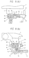
- Figures 8(A) and 8(B) and 9(A) and 9(B) are drawings centering on the capping unit 12
- Figure 8(A) and 9(A) show the state in which the carriage 1 is in the print area
- Figures 8(B) and 9(B) the state in which the carriage 1 is at the home position.
- Reference numeral 49 depicts the above-mentioned slider.
- a projection 50 formed on the bottom moves with a base 48 as a slide face.
- the print area side is attached to a link 52 disposed on the base 48 and is energized in the upward direction and the print area direction by a spring 54 placed between the base 48 and the slider 49.
- the face on which the projection 50 of the slider 49 slides is composed of a slope 55 with the print area side down and a plane 56 at the height for pressing the cap member 80 against the recording head 7 when the recording head arrives at the home position.
- the slider 49 has guides 58 which widen and open in the print area direction side, conforming to the width of the recording head 7 on both sides, and a lock piece 61 engaged with a flange piece 60 of the carriage 1 in the external end portion.
- the cap member 80 is formed as an elastic cup having an air inlet 65 communicated with the atmospheric opening 64 via a duct 63 on the top and an intake 66 at which negative pressure from the pump unit 13 works.
- Ducts 63, 67 connecting the air inlet 65 and the atmospheric opening 64 and the intake 66 and the pump tube 31 are formed by injection molding so that they become integral with the elastic cup.
- the atmospheric opening 64 is opened and closed by the valve mechanism 41.
- a tube defining the duct 67 is connected to the pump tube 31 via a connection hole 72 pierced in the slider 49.
- the cap member 80 is housed in a reception member 81 made of high-rigid material such as macromolecular material so that the opening margin portion of the cap member exposes, and contains an ink absorber 82 made of a porous substance for absorbing ink.
- the reception member 81 has two shafts 83 extending in the direction perpendicular to the direction of movement of the recording head 7 on the top and is formed with a hemispheric recess 84 on the bottom; the top is loosely supported by the slider 49 by the two shafts 83 ( Figure 9(B)), and the bottom is loosely supported by a hemispheric projection 85 projecting from the slider 49 for airtightly pressing the cap member 80 into contact with the nozzle opening face of the recording head 7 independently of the attitude of the recording head 7.
- the valve mechanism 41 comprises a valve body 92 opposed to the atmospheric opening 64 and secured to one end of a guide stick 91 always energized to the atmospheric opening 64 by a spring 90, a driving stick 95 energized outwardly by a spring 94 stronger than the spring 90 so that the opposite side to the print area always projects from a frame 93, and lock pieces 96 and 97 for engaging the guide rod 91 and the driving stick 95.
- the valve body 92 loses the suppression force of the driving stick 95 and abuts against the atmospheric opening 64 by energy of the spring 90 for disconnecting communication of the cap member 80 with the atmosphere.
- Reference numeral 15 indicates the cleaning unit in which a cleaning member 40, which is composed of laminated layers of a rubber plate 42 appropriate for a wiping operation on the outside and a sponge material 43 appropriate for rubbing operation on the print area side, is fixed to a frame 39 swingably secured to shafts 46 disposed on both sides of the capping unit 12 for moving between the cleaning position and the non-cleaning position as the carriage 1 moves.
- the frame 39 is loosely supported on one face by a long groove 100, and on the other by a round hole (not shown) to the shafts 46 disposed on both sides of the slider 49 supporting the cap member 80 so that it can switch with the round hole side as the center in the upward direction and in the direction perpendicular to the move direction of the recording head 7.
- the frame 39 is formed with a projection 102 extending downward to the center of the print side tip and is always energized in the print area direction and downward by pull spring 103 placed between the frame 39 and the slider 49.
- the frame 39 is also formed with release pieces 101 (described below) on both sides between which the move passage of the recording head 7 is sandwiched on the top and is formed with a cam face 104 on the side.
- the release piece 101 is formed as a triangular pole with the recording head passage side as the vertex, and when slopes 105, between which the vertex is sandwiched, contact the flag piece 60 of the carriage 1, is adapted to swing the frame 39 by angle ⁇ in the horizontal direction with the shaft 46 as the center for releasing engagement of the cam face 104 and a cam follower 106 (described below).
- the cam face has a first slope 111 defining a first passage for guiding the frame 39 upward when pushed in the direction outside the print area by the carriage 1 from stable point P1 contacting when the carriage 1 is in the non-abutting state, a second slope 112 defining a second passage horizontally extending in the direction outside the print area from the lower end of the first slope, a third slope 113 defining a third passage for raising the frame 39 to the cleaning position, a fourth slope 114 for holding the frame 39 at the cleaning position, and a fifth slope 115 for guiding the cam follower 106 to the first slope 111.
- each of the first slope 111 and second slope 112 is formed like a right angled triangle so that they can be overridden in moving in the directions indicated by arrows 116 and 117.
- the fourth slope 114 is selected as the height at which the cam follower 106 can override the slope when the frame 39 is swung.
- Step difference H is provided between stable point P1 and semistable point P2 so that the former point is placed at the position at which the cleaning member 40 does not abut against the nozzle opening face of the recording head 7 and so that the latter point is placed at the position at which the cleaning member 40 abuts against the nozzle opening face of the recording head 7.
- Figure 11 shows an ink cartridge appropriate for the ink jet recording system described above, wherein reference numeral 120 is a vessel forming the ink cartridges main unit.
- the vessel has an opening 121 on the top and is slightly tapered towards a bottom 122.
- An ink outlet 123 engaged elastically with and surrounding an ink supply needle 9 ( Figure 12) fixed to the recording head 7 is integral with the vessel 120 on the bottom 122.
- the ink outlet 123 has one end formed like a pipe projecting from the bottom end an opening 124 to which a filter 125 is welded.
- a step difference 126 is formed at the center of the inner face of the ink outlet 123.
- Packing material pressed against the ink supply needle 9 for maintaining the fluid-sealing state (in the embodiment, a rubber ring or so-called O ring 127) is housed on the tip opening sided and a film 128 through which the ink supply needle easily passes is welded to the outer opening portion for sealing.
- Two electrodes 130 and 131 are disposed near the bottom of the vessel 120; one is located in the vessel and the other in the ink outlet 123.
- Reference numeral 133 is a porous substance forming an ink absorber.
- the porous substance 133 has a section slightly larger than the opening 121 of the vessel 120 and is slightly higher than the vessel.
- the lower end portion of the porous substance 133 is pressed against the filter 125 of the ink outlet 123 for compression in response to the form of the ink outlet 123 and with its outer surface pressed by the side walls of the vessel 120, the porous substance is housed in the vessel 120 and is pressed against the bottom 122 by means of a cover 137 comprising an atmospheric communication port 135 and ribs 136 for sealing.
- ink is poured from the atmospheric communication port 135 under a negative pressure of 3.45 kPa (0.5 psi) or higher and absorbed into pores of the porous substance 133, thereby forming an ink cartridge.
- Figure 13 shows a controller which controls ink handling in the ink jet recording apparatus described above, wherein reference numeral 145 is a resistance value detection circuit for measuring electric resistance between the electrodes 130 and 131 disposed on the ink cartridge 140.
- the resistance value detection circuit 145 is adapted to apply an alternating voltage across the electrodes 130 and 131 at a given period, for example, every second, for measuring the resistance value.
- Reference numeral 146 indicates a controller, which is a microcomputer programmed so as to provide resistance value comparison unit 152 for comparing a reference resistance value stored in reference value storage unit 151 (described below) with a resistance value from the resistance value detection circuit 145, resistance value storage unit 153 for updating the resistance value from the resistance value detection circuit 145 in sequence and storing it, supply voltage detection unit 154 for detecting the voltage of a power supply circuit driving the printing apparatus lowering to a given value for outputting a signal, write unit 155 responsive to the signal from the supply voltage detection unit 154 for transferring data in the resistance value storage unit 153 and data from ink spout recovery operation monitor unit 157 (described below) to history storage unit 156 composed of a nonvolatile memory, and pump control unit 158 for controlling the pulse motor 4 based on data from the resistance value comparison unit 152.
- resistance value comparison unit 152 for comparing a reference resistance value stored in reference value storage unit 151 (described below) with a resistance value from the resistance value detection circuit
- the ink spout recovery operation monitor unit 157 turns on a flag.
- the unit 157 turns off the flag. If the cleaning operation aborts due to, for example, power failure during the cleaning, the unit 157 outputs the flag as data.
- the reference value storage unit 151 stores a first reference L 1 indicating the lower limit of a resistance value when an appropriate amount of ink exists in the recording head, a second reference L 2 indicating data of a resistance value at which the user is promoted to change the ink cartridge when the ink cartridge contains a small amount of remaining ink, a third reference L 3 indicating data of a high resistance value when the ink cartridge contains almost no remaining ink, a fourth reference L 4 indicating data of an extremely high resistance value when no ink cartridge is mounted, and a fifth reference L 5 indicating data of an extremely low resistance value to detect a different kind of ink, a short circuit of the electrodes, etc., as shown in Figure 18.
- the pump control unit 156 includes drive patterns for controlling the pulse motor 4 so as to enable suction modes in response to every situation, such as a small quantity of suction for pulling out ink during an initial filling ink, suction when the ink cartridge is replaced with a new one, suction to discharge ink collected in an exhaust passage of ink, a small quantity of suction for meniscus recovery operation, and processing for detaching the drive roller 36 from the tube 31 to terminate suction operation.
- Reference numeral 149 in Figure 13 is a display for displaying a message, etc.
- the initial filling mode is executed.
- the initial filling mode can be started, for example, by the user who turns on a power switch while holding an ink spout recovery command button on the printer cabinet.
- the ink cartridge 140 is mounted on the recording head 7.
- the ink supply needle 9 passes through the seal member 128 and arrives at the packing member 127, thereby connecting the ink cartridge via the packing member 127 to the trip of the ink supply needle 9 of the recording head in fluid-sealing relation.
- the pump control unit 158 rotates the paper feed motor 4 forward at low speed (step b in Figure 19), thereby transferring rotation force of the motor 4 via the wheel train 23 to the suction pump unit 13 for rotating the drive board 34, thereby causing the rollers 36 to move along the long groove to the outside and abut against the tube 31.
- the tube 31 is rubbed up by rotation of the motor 4 for generating weak negative pressure.
- the pump control unit 158 switches the pulse motor 4 to high speed rotation (step d in Figure 19), thereby causing strong negative pressure to act an the nozzle openings.
- Ink of about 15 cm 3 per minute, for example, is sucked out from the nozzle openings and therefore, air bubbles accumulating in the reservoir or pressure generation chamber of the recording head 7 at the initial filling with ink are discharged from the nozzle openings together with the ink flow.
- the pump control unit 158 stops the pulse motor 4 (step f in Figure 19), thereby causing the inside of the cap member 80 to gradually rise to atmospheric pressure.
- the pump control unit 158 again rotates the pulse motor 4 forward at low speed (step g in Figure 19) as described above. Then, weak negative pressure to the degree at which a very small amount of ink is spouted from the nozzle openings is generated in the cap member 80 and the meniscus of the nozzle openings disordered by high speed suction is restored to a state suitable for a printing operation.
- Very small air bubbles occurring at the high speed suction and air bubbles remaining in the sediment in the swirling state can be securely discharged by low speed suction.
- the low speed suction is carried out after the high speed suction is performed for the above-mentioned reason, but print operation can also be started immediately after the high speed suction.
- step h in Figure 19 When a time T4, enough for low speed suction, for example, two seconds, has elapsed (step h in Figure 19), the pulse motor 4 is again stopped (step i in Figure 19), and the inside of the cap member 80 is restored to atmospheric pressure, then the pulse motor 4 is rotated reversely at low speed a predetermined number of revolutions, namely, enough revolutions to move the rollers 36 abutting against the tube 31 in the center direction, thereby causing the drive rollers 36 to mode on the long groove of the drive board 34 slowly in the center direction and leave the tube 31. If the pulse motor 4 stops after forward rotation, the drive rollers 36, 36 remain abutting against the tube 31.
- the pump unit 13 generates positive pressure for the cap member 80.
- the generated pressure is extremely small and therefore before the pressure in the cap member 80 rises, the drive rollers 36 move on the long groove of the drive board 34 in the center direction and leave the tube 31. After this, the function of the pump is lost regardless of reverse rotation of the motor 4 (steps i, j).
- the suction operation of the pump unit 13 can be terminated without destroying the meniscus formed at the nozzle openings of the recording head 7.
- the suction operation can be terminated in the state in which the meniscus appropriate for printing is held without applying unnecessary positive pressure to the cap member 80.
- the resistance value detection circuit 145 detects the electric resistance value across the electrodes 130 and 131 at intervals of given time T5, for example, one second or during printing, every predetermined number of lines printed, for example, every line printed (step a in Figure 20).
- the resistance value is stored while the contents of the resistance value storage unit 153 are updated in sequence (step b in Figure 20), and is compared with data in the reference value storage unit 151 by the resistance value comparison unit 152 for monitoring the remaining amount of ink in the ink cartridge, etc., (step c in Figure 20).
- the resistance value across the electrodes exceeds the second reference L 2 . Then, a message to the effect that the level of ink in the ink cartridge is low is displayed prompting the user to prepare a new ink cartridge. Even if the resistance value across the electrodes exceeds the second reference L 2 , a small amount of ink remains for printing.
- a message is output requesting the user to replace the ink cartridge with a new one (step d in Figure 20). If the user responds to the message with replacement with a new ink cartridge (step e in figure 20), the cap member of the cap unit is mounted on the recording head (seep f in Figure 20).
- the resistance value across the electrodes is detected (step g in Figure 20) and is compared with resistance value across the electrodes detected just before the ink cartridge is replaced. As a result of the comparison, if the resistance value across the electrodes detected after the ink cartridge is replaced is greater than that detected before the replacement (step h in Figure 20), it is decided that there is a possibility that the user again has mounted the once drawn-out ink cartridge intact. That is, it is possible that the resistance across the electrodes increases because air bubbles entered the ink supply port when the ink cartridge 140 was drawn out and again mounted.
- the pump control unit 158 rotates the pulse motor 4 forward at high speed (step i in Figure 20), causing strong negative pressure to act on the nozzle openings for sucking out, for example, ink of about 15cm 3 per minute from the nozzle openings, thereby discharging air bubbles around the ink supply port occurring when the ink cartridges 140 was again mounted from the nozzle openings together with the ink flow.
- a predetermined time T7 for example, one second has elapsed (step j in Figure 20)
- the resistance across the electrodes is again measured for determining whether or not the measured resistance value is lower than the preceding value (step k in Figure 20).
- step w the pump control unit 158 continues rotating the pulse motor 4 forward at high speed (step o in Figure 20), causing a sufficient flow of ink from the ink cartridge 140 into the ink supply passage and the recording head, thereby securely discharging air bubbles.
- the pump control unit 158 stops the suction operation (step q in Figure 20), thereby causing the inside of the cap member 80 to gradually rise to atmospheric pressure.
- the pump control unit 158 rotates the pulse motor 4 forward at low speed (step r in Figure 20) as described above. Then, weak negative pressure sufficient to suppress a spout of ink from the nozzle openings is generated in the cap meter 80, and the meniscus of the nozzle openings disordered by high speed suction is restored to the state suitable for print operation. Very small air bubbles occurring at the high speed suction and air bubbles remaining in the sediment in the swirling state can be securely discharged by low speed suction.
- the pulse motor 4 is stopped (step t in Figure 20) and the inside of the cap member 80 is restored to atmospheric pressure. Then, the pulse motor 4 is rotated reversely at low speed a predetermined number of revolutions to move the rollers 36 abutting against the tube 31 in the center direction (step u in Figure 20). The pulse motor 4 is stopped (step v in Figure 20), thereby terminating the suction operation in the state in which the meniscus appropriate for printing is held without applying unnecessary positive pressure to the cap member 80. Then the wiping operation of the recording head is performed (step w in Figure 20) to provide for the next print operation.
- the cleaning member 40 also rises and is set to a position at which it contacts the front of the recording head 7 ( Figure 16 A). In this state, if the carriage 1 is further moved toward the print area, a blade member 42 becomes the top side and abuts against the recording head 7, thus ink drops attached by suction are removed from the surrounding of the nozzle openings of the recording head 7.
- the recording head 7 When the carriage 1 moves to the print area side, the recording head 7 is set to an air suction position (position III in Figure 14) through a cleaner set position [position II in Figure 14). During the move, the slider 49 moves on the plane 56, and thus the cap member 80 continues to seal the front of the recording head 7. At this position, the valve body 92 is removed from the atmospheric opening 64 by means of the drive stick 95. Thus, if the pulse motor 4 is rotated forward, negative pressure of the pump unit 13 acts on the cap member 80. However, since the atmospheric opening 64 is open, negative pressure does not act on the recording head 7 and only waste ink remaining in the absorber 82 and the tube 31 is sucked out and sent to the waste ink tank 30.
- the print operation performed by the recording head 7 is temporarily stopped and the recording head 7 is moved toward the home position. While the recording head is moved toward the home position, the flange piece 60 of the carriage 1 passes through the release piece 101 and subsequently the recording head 7 arrives at the guides 58. The slider 49 is guided by the guides 58 to alignment with the center of the recording head 7. Further, the carriage 1 moves, the flange piece 60 abuts against the lock piece 61, and the recording head 7 is positioned at a flushing position (position V in Figure 14) opposite the cap member 80 at a given gap length.
- the recording head 7 causes ink to be spouted out independently of a print signal from nozzle openings unused during the printing, thereby discharging ink in the nozzle openings not used during the printing into the cap member 80 to prevent ink in the nozzle openings from increasing in viscosity and to prevent the nozzle openings from drying.
- the resistance across the electrodes is detected every predetermined time T 5 , for example, every second or each time one line of printing is completed, as described above.
- the detected resistance values are transferred to the resistance value storage unit 153 in sequence for updating the resistance value data.
- a signal is output from the supply voltage detection unit 154.
- the write unit 155 transfers the resistance value stored in the resistance value storage unit 153 to the history. storage unit 156 for storage.
- a large-capacitance capacitor for smoothing is connected to the power supply circuit and the operation voltage can be maintained for the time required to transfer data for storage.
- the resistance value comparison unit 152 compares the preceding resistance value across the electrodes stored in the resistance value storage unit 156 with the resistance value across the electrodes just after the power is turned on. If the difference between them, ⁇ r, is greater than a predetermined value, namely, the resistance value change caused by temperature, etc., ⁇ R (step b in Figure 21), the cap member 80 is pressed into contact with the recording head 7 (step c in Figure 21).
- step motor 4 is rotated forward at high speed (step d in Figure 21), thereby sucking out ink from the recording head 7 and discharging ink around the ink outlet 123 of the ink cartridge 140 via the recording head 7, thereby discharging air bubbles which entered by demounting or mounting the ink cartridge when the power was turned off.
- step e in Figure 21 When the predetermined time T 9 has elapsed (step e in Figure 21), the motor 4 is stopped (step f in Figure 21), and is then rotated forward at low speed to return the meniscus to the state proper for printing and to discharge the air bubbles formed during high speed suction and the air bubbles remaining in the sediment (step g in Figure 21), the motor 4 is stopped and the pressure in the cap member 80 changes from negative to atmospheric pressure (step I in Figure 21). Next, the motor 4 is rotated reversely at low speed and the rollers 36 are separated from the tube 31 to provide for paper feed (steps j and k in Figure 21). At this stage, the resistance value across the electrodes is compared with the second reference.
- step l in Figure 21 If it is determined that the ink cartridge 140 contains sufficient ink (step l in Figure 21), printing is enabled (step n in Figure 21); if the ink cartridge contains less ink, a message is output instructing the user to replace the ink cartridge with a new one (step m in Figure 21).
- the cleaning member 40 is raised and the printing head 7 is moved to the print area side. Then, the carriage 1 is moved in the direction opposite to the wiping operation (arrow C direction in Figure 16B). Subsequently, with the rubbing member 43 on the top, the cleaning member 40 contacts the nozzle opening face of the recording head 7 for rubbing the nozzle opening face.
- the carriage 1 When the operation sequence thus terminates with no print data and the transition to the stop state is made, the carriage 1 is moved toward the standby position, thereby causing the slider 49 to climb up the slope 55 as the recording head 7 moves. When it further moves toward the outside of the print area, passage of the recording head 7 is detected by the home position detection unit (not shown) in the process.
- the pulse motor for piper feed when suction terminates, the pulse motor for piper feed is rotated at low speed and the rollers 36 are separated from the tube 31 without causing positive pressure to act on the recording head 7.
- the cap member 80 is detached from the recording head 7 when the cap member is returned to positive pressure after suction terminates, the meniscus will not be destroyed even if the pulse motor is rotated reversely at high speed.
- the ink spout recovery operation monitor unit 157 turns on the flag, and when the ink recovery operation sequence terminates, turns off the flag.
- the operation voltage drops, which is detected by the supply voltage detection unit 154 and the flag is stored in the history storage unit 156 by the write unit 155.
- the data in the history storage unit 156 is read out, and if the read data contains data indicating the ink spout recovery operation flag, the ink spout recovery operation is performed before print operation is started.
- the ink spout recovery operation is again executed, thereby forming the normal meniscus for printing in the optimum state.
- the ink jet recording apparatus comprises a recording head communicated via an ink supply member with an ink tank comprising electrodes for detecting a remaining amount of ink and being responsive to a print signal for spouting ink drops from nozzle openings onto recording paper, capping means abutting against the front of the recording head for holding the nozzle openings in an airtight state, suction means for supplying negative pressure to the capping unit and sucking out ink in the capping unit into a waste ink tank, resistance value detection means for detecting electric resistance across the electrodes for detecting a remaining amount of ink, reference value storage means for storing a resistance value across the electrodes relative to the remaining amount of ink in the ink tank as a reference value, resistance value comparison means for comparing the resistance across the electrodes with the reference value, and pump control means responsive to the resistance value comparison result for controlling the operation of the suction means.
- the ink amount and the state of the ink tank can be determined precisely for automatically selecting the ink suction mode in response to the state, enabling the user to execute initial filling which is otherwise comparatively hard to perform.
- air bubbles entering due to improper handling of the ink tank such as during remounting can also be detected for proper automatic processing by ink suction.
Abstract
Description
- The present invention relates to an ink jet recording apparatus.
- An on-demand ink jet recording apparatus which jets ink pressurized at a pressure generation chamber through a nozzle onto recording paper as ink droplets for recording print data exhibits substantial problems. Among these problems are a rise in viscosity caused by evaporation of an ink solvent from nozzle openings and print failure caused by drying of ink, adhesion of dust, and mixing of air bubbles. Thus, an ink jet recording apparatus of this type is generally provided with a capping device for sealing the nozzle openings when no printing is being performed and a device for cleaning around the nozzle openings as required.
- A proposed capping device includes a slider which is moved by a carriage to a home position along a slant guide face disposed on a frame to the nozzle opening face side of a head, and a cap disposed on the surface of the slider is pressed against the recording head for sealing the nozzle openings, for example. Such an arrangement is disclosed in Japanese Patent Laid-Open No. Hei 1-125239.
- For such an ink jet recording apparatus, an ink tank is furnished in cartridge form which provides a convenient ink supply. When the ink has been consumed, the ink cartridge is replaced with a new one. One such ink cartridge is disclosed in Japanese Patent Laid-Open No. Hei 2-187364, in which a porous substance forming an ink absorber is housed in the ink cartridge. Annular packing material is disposed on the tip of an ink outlet for sealing. Since ink can be easily supplied by simply changing ink cartridges, the ink cartridge is very useful in preventing polution caused by ink leakage, etc., at the ink supply. On the other hand, the ink cartridge has a disadvantage in that air bubbles are prone to enter the ink cartridge by piston action between an ink supply needle on the main unit side and the ink outlet of the ink cartridge when the ink supply needle is inserted.
- Further, because of the ease of changing the ink supply, the ink cartridge is prone to be removed and then remounted even when ink remains in the cartridge. As a result, air bubbles enter the ink cartridge by the piston action and cause print failure to occur.
- Document EP-A-0 452 119 discloses an ink jet recording apparatus with a recording head, capping means abutting against a front of the recording head and suction means for supplying negative pressure to the capping means.
- It is therefore an object of the invention to provide an ink jet recording apparatus which can more perfectly perform ink handling for a recording head, such as supplying ink from an ink cartridge to the recording head, and to solve the problem of the nozzle openings clogging during printing.
- This object is solved by the ink jet recording apparatus of
independent claim 1. Further advantageous features, aspects and details of the invention are evident from the dependent claims, the description and the drawings. - The ink jet recording apparatus of the present invention comprises:
- means for producing a print signal;
- a recording head being communicated via an ink supply member with an ink tank and being responsive to a print signal for spouting ink drops from nozzle openings to recording paper;
- capping means abutting against a front of said recording head for holding the nozzle openings in an airtight state;
- suction means for supplying negative pressure to said capping means and sucking ink from said recording head through said capping means into a waste ink holding means;
- detection means for detecting ink remaining in said ink tank; and
- suction control means responsive to a result of the detection of said remaining ink detection means for controlling operations of said suction means.
- According to a preferred embodiment of the invention the suction control means controls a flow rate of the ink suction performed by the suction means.
- According to a further preferred embodiment of the invention, the suction means executes suction at a high flow rate and subsequently at a low flow rate.
- According to a further preferred embodiment of the invention the suction control means controls a flow amount of the ink suction performed by the suction means.
- According to a further preferred embodiment of the invention the suction means executes suction at a high flow rate and subsequently at a low flow rate within a constant time period.
- The ink jet recording apparatus of the present invention comprises means for judging or determining a remaining amount of ink and suction control means responsive to the result of the judgement or determination of the remaining amount of ink judging means, instead of the electrodes and remaining members (see
reference numerals - According to an aspect of the present invention, an ink jet recording apparatus comprises:
- a recording head being communicated with an ink tank via an ink supply member and being responsive to a print signal for spouting ink drops from nozzle openings to recording paper,
- capping means abutting against a front of said recording head for holding the nozzle openings in an airtight state, and
- suction means for supplying negative pressure to said capping means and sucking ink from said recording head through said capping means into a waste ink holding means, said suction means being formed as a peristaltic pump comprising an elastic tube and a plurality of rollers, said rollers pressing against said tube of suction operation by rotation of a motor in one direction, said tube being released from said pressure by rotation of said motor in another direction, wherein after the suction process terminates, the rotation in said another direction is executed at a lower speed than the rotation in said one direction.
- According to another aspect of the invention, in said suction means the outside of said elastic tube connected to said capping means and said waste ink tank is held by a cover case so as to make it substantially like a circle and the inner surface thereof is pressed by two rollers pivotally secured to a drive board driven by a rotation shaft.
- According to a further aspect of the invention the capping means is formed like a cup with elastic material.
- According to a further aspect of the invention the motor drives a paper feed roller in said one direction.
- In a device for handling ink in an ink jet recording apparatus a recording head is moved across the width of recording paper and jets ink drops onto the recording paper in response to print data for forming an image.
- According to an aspect of the invention, there is provided an ink jet recording apparatus comprising a recording head communicated via an ink supply member with an ink tank comprising electrodes for detecting a remaining amount of ink and being responsive to a print signal for spouting ink drops from nozzle openings to recording paper, capping means abutting against the front of the recording head for holding the nozzle openings in an airtight state, suction means for supplying negative pressure to the capping means and sucking out ink in the capping means into a waste ink tank, resistance value detecting means for detecting resistance across the electrodes for detecting a remaining amount of ink, reference value storage means for storing a resistance value across the electrodes relative to the remaining amount of ink in the ink tank as a reference value, resistance value comparison means for comparing the resistance across the electrodes with the reference value, and suction control means responsive to the resistance value comparison result for controlling the operation of the suction means.
- Since the resistance of the resistance value detection means connected to the electrodes of the ink cartridge changes in response to the presence or absence of the ink cartridge and the communication state with the recording head, the resistance is compared with data in the reference value storage means to determine whether or not the ink cartridge is mounted and how much ink the ink cartridge contains. Based on the determination result, the suction mode of the suction means is selected.
- Another aspect of the invention is a method for operating an ink jet recording apparatus. The method allows the determination whether or not an ink tank is mounted or remounted to the apparatus, how much ink is in the ink tank etc. Based on the result of the determination, a motor is controlled by a pump control unit to select an appropriate suction mode of ink from the recording head.
- According to another aspect of the invention, an ink jet recording apparatus comprises:
- means for producing a print signal,
- a recording head being communicated via an ink supply member with an ink tank comprising electrodes for detecting a remaining amount of ink and being responsive to a print signal for spouting ink drops from nozzle openings to recording paper,
- capping means abutting against a front of said recording head for holding the nozzle openings in an airtight state,
- suction means for supplying negative pressure to said capping means and sucking ink through said capping means into a waste ink tank,
- resistance value detection means for detecting electric resistance across the electrodes for detecting a remaining amount of ink,
- reference value storage means for storing a resistance value across the electrodes relative to the remaining amount of ink in the ink tank as a reference value,
- resistance value comparison means for comparing the resistance across the electrodes with the reference value, and
- suction control means responsive to a resistance value comparison result for controlling operations of said suction means.
- In this ink jet recording apparatus, the suction control means preferably comprises an ink tank replacement mode in which, when an ink tank is replaced with a new one, a resistance across the electrodes detected just before the ink tank is replaced is compared with that detected after the ink tank is replaced, and the suction of the ink through said capping means is executed if the latter resistance is smaller than the former.
- Further, in this ink jet recording apparatus the suction means preferably executes suction at a high flow rate and subsequently at a low flow rate.
- Further, in this ink jet recording apparatus the suction control means preferably comprises an ink tank replacement mode in which, when the ink tank is replaced with a new one, said suction control means compares a resistance across the electrodes just before replacement of the ink tank with a resistance value after the replacement, and if the former is smaller than the latter, executes suction at a high flow rate by said suction means while detecting a change in the resistance across the electrodes, and if the resistance across the electrodes drops as the suction is executed, continues the suction at the high speed for a predetermined time.
- Further, in this ink jet recording apparatus, in said ink tank replacement mode, after the suction at the high speed is continued for said predetermind time, subsequent suction at low rate is executed.
- Further, in this ink jet recording apparatus, if the resistance value across the electrodes does not drop when the suction is executed at the high speed, the suction operation is stopped.
- Further, this ink jet recording apparatus preferably comprises history storage means for storing at least resistance across the electrodes at power off in a nonvolatile manner and comparison means for instructing an ink suction operation to be executed if the resistance value across the electrodes is higher than the resistance value stored in said history storage means when power is turned on.
- Further, in this ink jet recording apparatus, when an ink tank is first mounted, suction at a low flow rate is first executed, and subsequently suction at a high flow rate is executed.
- Further, in this ink jet recording apparatus, suction in a high flow rate is first executed, and subsequently suction at a low flow rate is executed in a sequence of ink spout recovery operation steps including the suction operation.
- Further, in this ink jet recording apparatus said reference value storage means stores at least a reference indicating that the ink tank contains sufficient ink, another reference for instructing a user to replace the ink tank with a new one, and a further reference for detecting a state in which no ink tank is mounted.
- According to another aspect of the invention an ink jet recording apparatus comprises:
- a recording head being communicated with an ink tank via an ink supply member and being responsive to a print signal for spouting ink drops from nozzle openings to recording paper,
- capping means abutting against a front of said recording head for holding the nozzle openings in an airtight state,
- suction means for supplying negative pressure to said capping means and sucking ink in said capping means into a waste ink tank, and
- storage means for storing an ink spout recovery operation termination form indicating whether or not a sequence of ink spout recovery operation steps containing the suction operation terminates, wherein when power is turned on, data indicating the ink spout recovery operation termination form is read out and if it indicates that the operation sequence does not terminate, the ink spout recovery operation is again executed.
- According to another aspect of the invention an ink jet recording apparatus comprises:
- a recording head being communicated via an ink supply member with an ink tank comprising electrodes for detecting a remaining amount of ink and being responsive to a print signal for spouting ink drops from nozzle openings to recording paper, capping means abutting against a front of said recording head for holding the nozzle openings in an airtight state, suction means for supplying negative pressure to said capping means and sucking out ink in said capping means into a waste ink tank,
- resistance value detection means for detecting a resistance across the electrodes for detecting a remaining amount of ink, reference value storage means for storing a resistance value across the electrodes indicating that the ink tank contains sufficient ink as a reference value,
- resistance value comparison means for comparing the resistance value across the electrodes with the reference value, and
- suction control means responsive to a comparison result of the resistance values for controlling operation of said suction means, wherein if the resistance value from said resistance value detection means after ink tank replacement indicates a value smaller than the reference value, said suction control means holds said suction means inoperative.
- According to another aspect of the invention an ink jet recording apparatus comprises
- a recording head being communicated with an ink tank via an ink supply member and being responsive to a print signal for spouting ink drops from nozzle openings to recording paper,
- capping means abutting against a front of said recording head for holding the nozzle openings in an airtight state,
- suction means for supplying negative pressure to said capping means and sucking ink in said capping means into a waste ink tank, and
- suction control means for causing said suction means to execute suction at a low flow rate and suction at a high flow rate.
- In this ink jet recording apparatus when an ink tank is first mounted, suction at a low flow rate is first executed, and subsequently suction at a high flow rate is executed.
- Further in this ink jet recording apparatus suction in a high flow rate is first executed, and subsequently suction at a low flow rate is executed in a sequence of ink spout recovery operation steps including the suction operation.
- Finally, the ink jet recording apparatus of the present invention comprises a valve mechanism (see reference numeral 41), an ambient air opening (see reference numeral 64) and a slider (see reference numeral 49), as shown especially in Fig. 8(A) and 8(B).
- Preferred embodiments of the invention are now explained with reference to the drawings.
- Figure 1 is a perspective view showing the structure of the print mechanism periphery of an ink jet recording apparatus to which an ink supply device of the invention is applied;
- Figure 2 is an enlarged view of an ink jet recording head mounted on a carriage in the ink jet recording apparatus;
- Figure 3 is an enlarged view of an ink tank mounted on the carriage in the ink jet recording apparatus;
- Figure 4 is an enlarged view of a pump unit and a capping unit in the ink jet recording apparatus;
- Figure 5 is a top view showing the location relationship between the pump unit and the capping unit in the ink jet recording apparatus;
- Figure 6 is a side view showing the relationship between the pump unit and a pulse motor for paper feed for driving the pump unit in the ink jet recording apparatus;
- Figure 7 is a sectional view showing one embodiment of the pump unit used with the invention;
- Figures 8(A) and 8(B) are a pair of drawings centering on the capping unit, Figure 8(A) showing a state in which the recording head exists in a print area and Figure 8(B) showing a state in which the recording head exists at a standby position;
- Figures 9(A) and 9(B) are a pair of drawings showing an embodiment of a cap member which is a component of the capping unit, Figure 9(A) showing the section parallel to a move passage of the recording head and Figure 9(B) showing the section perpendicular to the passage of the recording head;
- Figure 10 is a drawing showing an embodiment of a cam face attached to a cleaning unit;
- Figure 11 is a sectional view showing an embodiment of an ink cartridge used with the ink jet recording apparatus;
- Figure 12 is an illustration showing a state in which the ink cartridge in Figure 11 is mounted on a cartridge;
- Figure 13 is a block diagram showing one embodiment of a controller which controls ink handling in the ink jet recording apparatus;
- Figure 14 is an illustration showing the relationship between carriage position and operation;
- Figures 15(A) and 15(B) are illustrations showing capping unit motion and cleaning unit motion according to recording head positions;
- Figures 16(A) and 16(B) are illustrations showing capping unit operation and cleaning unit operation;
- Figure 17 is a drawing showing capping unit operation and cleaning unit operation;
- Figure 18 is a chart showing the relationship between remaining amounts of ink in an ink cartridge and resistence across electrodes;
- Figure 19 is a flowchart showing initial filling operation of ink cartridge;
- Figure 20 is a flowchart showing operation when an ink cartridge is replaced with a new one; and
- Figure 21 is a flowchart showing a process which occurs just after the power is turned on with an ink cartridge mounted.
- Referring now to the accompanying drawings, there are shown preferred embodiments of the invention.
- Figure 1 shows in perspective view the arms of a print mechanism of an ink jet recording apparatus to which the invention is applied. In Figure 1,
reference numeral 1 is a carriage which is supported by aguide member 2 and is connected via atiming belt 3 to a pulse motor (not shown) and can reciprocate in parallel to aplaten 5. - A
recording head 7 is mounted on thecarriage 1 in such a manner that nozzle openings are directed toprinting paper 6, as shown in Figure 2. Anink cartridge 8 is detachably mounted on the top of therecording head 7, as shown in Figure 3. A base forming therecording head 7 is provided with an ink needle 9 (as described below) by which an ink supply passage of the recording head and theink cartridge 8 are connected. - According to this structure, when a drive signal from a head drive circuit (not shown) is received via a
flexible cable 10, ink flows into the recording head from the ink cartridge and dots can be formed on the recording paper connectively. - Referring again to Figure 1, a
capping unit 12 and a suction pump unit 13 (described below) are located outside the print area of thecarriage 1. The cappingunit 12 is integral with thesuction pump unit 13 for convenience of assembly and maintenance, as shown in Figure 4. - Figures 5 and 6 are views showing the top and section around the capping unit, wherein
reference numeral 20 indicates a paper feed roller, with agear 22 secured to one end of arotation shaft 21, which is connected to or disconnected from apulse motor 4 for paper feed via awheel train 23 which also serves as a connection switch mechanism. That is, when thewheel train 23 moves in the leftward direction in Figure 5, thewheel train 23 meshes with thegear 22, enabling supply of recording paper, and when thewheel train 23 moves in the rightward direction in Figure 5, thewheel train 23 meshes with a driving gear 25 (Figure 4) of thesuction pump unit 13, generating negative pressure. - Figure 7 shows an embodiment of the
pump unit 13. It is formed as a so-called peristaltic pump in which the outside of apump tube 31 connected acap member 80 and awaste ink tank 30 is held by acover case 32 so as to make it substantially like a circle and the inner peripheral surface thereof is pressed by tworollers drive board 34 driven by arotation shaft 33. Therollers drive board 34, and are secured so that when thepulse motor 4 for paper feed rotates forward, therollers cover case 32 and pivot while pressing against thetube 31 and so that when thepulse motor 4 rotates reversely for paper feed, the rollers move in the center direction for departing from thetube 31. - Referring again to Figure 5 and 6,
reference numeral 12 indicates the above-mentioned capping unit, which is located outside the print area of the passage of the carriage and which includes acap member 80 formed like a cup with elastic material so that it occupies a capping position covering the nozzle opening face of therecording head 7 and a non-capping position departing from the nozzle opening face in association with the movement of the recording head 7 (as described below), and avalve mechanism 41 for opening and closing communication with anatmospheric opening 64. These are installed on aslider 49 that can move parallel to the direction of motion of thecarriage 1 and can move up and down. - Figures 8(A) and 8(B) and 9(A) and 9(B) are drawings centering on the
capping unit 12, Figure 8(A) and 9(A) show the state in which thecarriage 1 is in the print area, and Figures 8(B) and 9(B) the state in which thecarriage 1 is at the home position. -
Reference numeral 49 depicts the above-mentioned slider. Aprojection 50 formed on the bottom moves with a base 48 as a slide face. The print area side is attached to alink 52 disposed on thebase 48 and is energized in the upward direction and the print area direction by aspring 54 placed between the base 48 and theslider 49. The face on which theprojection 50 of theslider 49 slides is composed of aslope 55 with the print area side down and aplane 56 at the height for pressing thecap member 80 against therecording head 7 when the recording head arrives at the home position. Theslider 49 hasguides 58 which widen and open in the print area direction side, conforming to the width of therecording head 7 on both sides, and alock piece 61 engaged with aflange piece 60 of thecarriage 1 in the external end portion. - The
cap member 80 is formed as an elastic cup having anair inlet 65 communicated with theatmospheric opening 64 via aduct 63 on the top and anintake 66 at which negative pressure from thepump unit 13 works.Ducts air inlet 65 and theatmospheric opening 64 and theintake 66 and thepump tube 31 are formed by injection molding so that they become integral with the elastic cup. Theatmospheric opening 64 is opened and closed by thevalve mechanism 41. A tube defining theduct 67 is connected to thepump tube 31 via aconnection hole 72 pierced in theslider 49. - As shown in Figures 9(A) and 9(B), the
cap member 80 is housed in areception member 81 made of high-rigid material such as macromolecular material so that the opening margin portion of the cap member exposes, and contains anink absorber 82 made of a porous substance for absorbing ink. Thereception member 81 has twoshafts 83 extending in the direction perpendicular to the direction of movement of therecording head 7 on the top and is formed with ahemispheric recess 84 on the bottom; the top is loosely supported by theslider 49 by the two shafts 83 (Figure 9(B)), and the bottom is loosely supported by ahemispheric projection 85 projecting from theslider 49 for airtightly pressing thecap member 80 into contact with the nozzle opening face of therecording head 7 independently of the attitude of therecording head 7. - Referring again to Figures 8(A) and 8(B), the
valve mechanism 41 comprises avalve body 92 opposed to theatmospheric opening 64 and secured to one end of aguide stick 91 always energized to theatmospheric opening 64 by aspring 90, a drivingstick 95 energized outwardly by aspring 94 stronger than thespring 90 so that the opposite side to the print area always projects from aframe 93, and lockpieces guide rod 91 and the drivingstick 95. Thus, when the drivingrod 95 is pushed into the state shown in Figure 8(B) as therecording head 7 moves, thevalve body 92 loses the suppression force of the drivingstick 95 and abuts against theatmospheric opening 64 by energy of thespring 90 for disconnecting communication of thecap member 80 with the atmosphere. -
Reference numeral 15 indicates the cleaning unit in which a cleaningmember 40, which is composed of laminated layers of arubber plate 42 appropriate for a wiping operation on the outside and asponge material 43 appropriate for rubbing operation on the print area side, is fixed to aframe 39 swingably secured toshafts 46 disposed on both sides of thecapping unit 12 for moving between the cleaning position and the non-cleaning position as thecarriage 1 moves. Theframe 39 is loosely supported on one face by along groove 100, and on the other by a round hole (not shown) to theshafts 46 disposed on both sides of theslider 49 supporting thecap member 80 so that it can switch with the round hole side as the center in the upward direction and in the direction perpendicular to the move direction of therecording head 7. Theframe 39 is formed with aprojection 102 extending downward to the center of the print side tip and is always energized in the print area direction and downward bypull spring 103 placed between theframe 39 and theslider 49. Theframe 39 is also formed with release pieces 101 (described below) on both sides between which the move passage of therecording head 7 is sandwiched on the top and is formed with acam face 104 on the side. - The
release piece 101 is formed as a triangular pole with the recording head passage side as the vertex, and whenslopes 105, between which the vertex is sandwiched, contact theflag piece 60 of thecarriage 1, is adapted to swing theframe 39 by angle θ in the horizontal direction with theshaft 46 as the center for releasing engagement of thecam face 104 and a cam follower 106 (described below). - Referring to Figure 10, the cam face has a
first slope 111 defining a first passage for guiding theframe 39 upward when pushed in the direction outside the print area by thecarriage 1 from stable point P1 contacting when thecarriage 1 is in the non-abutting state, asecond slope 112 defining a second passage horizontally extending in the direction outside the print area from the lower end of the first slope, athird slope 113 defining a third passage for raising theframe 39 to the cleaning position, afourth slope 114 for holding theframe 39 at the cleaning position, and afifth slope 115 for guiding thecam follower 106 to thefirst slope 111. - The section of each of the
first slope 111 andsecond slope 112 is formed like a right angled triangle so that they can be overridden in moving in the directions indicated byarrows fourth slope 114 is selected as the height at which thecam follower 106 can override the slope when theframe 39 is swung. Step difference H is provided between stable point P1 and semistable point P2 so that the former point is placed at the position at which the cleaningmember 40 does not abut against the nozzle opening face of therecording head 7 and so that the latter point is placed at the position at which the cleaningmember 40 abuts against the nozzle opening face of therecording head 7. - Figure 11 shows an ink cartridge appropriate for the ink jet recording system described above, wherein
reference numeral 120 is a vessel forming the ink cartridges main unit. The vessel has anopening 121 on the top and is slightly tapered towards a bottom 122. Anink outlet 123 engaged elastically with and surrounding an ink supply needle 9 (Figure 12) fixed to therecording head 7 is integral with thevessel 120 on the bottom 122. - The
ink outlet 123 has one end formed like a pipe projecting from the bottom end anopening 124 to which afilter 125 is welded. - A
step difference 126 is formed at the center of the inner face of theink outlet 123. Packing material pressed against theink supply needle 9 for maintaining the fluid-sealing state (in the embodiment, a rubber ring or so-called O ring 127) is housed on the tip opening sided and afilm 128 through which the ink supply needle easily passes is welded to the outer opening portion for sealing. Twoelectrodes vessel 120; one is located in the vessel and the other in theink outlet 123. -
Reference numeral 133 is a porous substance forming an ink absorber. Theporous substance 133 has a section slightly larger than theopening 121 of thevessel 120 and is slightly higher than the vessel. The lower end portion of theporous substance 133 is pressed against thefilter 125 of theink outlet 123 for compression in response to the form of theink outlet 123 and with its outer surface pressed by the side walls of thevessel 120, the porous substance is housed in thevessel 120 and is pressed against the bottom 122 by means of acover 137 comprising anatmospheric communication port 135 andribs 136 for sealing. Further, with theink outlet 123 sealed, ink is poured from theatmospheric communication port 135 under a negative pressure of 3.45 kPa (0.5 psi) or higher and absorbed into pores of theporous substance 133, thereby forming an ink cartridge. - Figure 13 shows a controller which controls ink handling in the ink jet recording apparatus described above, wherein
reference numeral 145 is a resistance value detection circuit for measuring electric resistance between theelectrodes ink cartridge 140. The resistancevalue detection circuit 145 is adapted to apply an alternating voltage across theelectrodes -
Reference numeral 146 indicates a controller, which is a microcomputer programmed so as to provide resistancevalue comparison unit 152 for comparing a reference resistance value stored in reference value storage unit 151 (described below) with a resistance value from the resistancevalue detection circuit 145, resistancevalue storage unit 153 for updating the resistance value from the resistancevalue detection circuit 145 in sequence and storing it, supplyvoltage detection unit 154 for detecting the voltage of a power supply circuit driving the printing apparatus lowering to a given value for outputting a signal, writeunit 155 responsive to the signal from the supplyvoltage detection unit 154 for transferring data in the resistancevalue storage unit 153 and data from ink spout recovery operation monitor unit 157 (described below) tohistory storage unit 156 composed of a nonvolatile memory, and pumpcontrol unit 158 for controlling thepulse motor 4 based on data from the resistancevalue comparison unit 152. When the cleaning process is executed, the ink spout recoveryoperation monitor unit 157 turns on a flag. When the cleaning process terminates normally as an operation sequence, theunit 157 turns off the flag. If the cleaning operation aborts due to, for example, power failure during the cleaning, theunit 157 outputs the flag as data. - The reference
value storage unit 151 stores a first reference L1 indicating the lower limit of a resistance value when an appropriate amount of ink exists in the recording head, a second reference L2 indicating data of a resistance value at which the user is promoted to change the ink cartridge when the ink cartridge contains a small amount of remaining ink, a third reference L3 indicating data of a high resistance value when the ink cartridge contains almost no remaining ink, a fourth reference L4 indicating data of an extremely high resistance value when no ink cartridge is mounted, and a fifth reference L5 indicating data of an extremely low resistance value to detect a different kind of ink, a short circuit of the electrodes, etc., as shown in Figure 18. - The
pump control unit 156 includes drive patterns for controlling thepulse motor 4 so as to enable suction modes in response to every situation, such as a small quantity of suction for pulling out ink during an initial filling ink, suction when the ink cartridge is replaced with a new one, suction to discharge ink collected in an exhaust passage of ink, a small quantity of suction for meniscus recovery operation, and processing for detaching thedrive roller 36 from thetube 31 to terminate suction operation.Reference numeral 149 in Figure 13 is a display for displaying a message, etc. - Next, the operation of the apparatus thus configured is described.
- Before the printing apparatus is used, the initial filling mode is executed. The initial filling mode can be started, for example, by the user who turns on a power switch while holding an ink spout recovery command button on the printer cabinet. Before or after the initial filling mode is started, the
ink cartridge 140 is mounted on therecording head 7. At the time, if the position of theink outlet 123 of theink cartridge 140 is adjusted to the position of theink supply needle 9 of therecording head 7 and theink cartridge 140 is pushed vertically, theink supply needle 9 passes through theseal member 128 and arrives at the packingmember 127, thereby connecting the ink cartridge via the packingmember 127 to the trip of theink supply needle 9 of the recording head in fluid-sealing relation. - After this, when the
cap unit 12 is mounted on the nozzle openings of the recording head 7 (step a in Figure 19), thepump control unit 158 rotates thepaper feed motor 4 forward at low speed (step b in Figure 19), thereby transferring rotation force of themotor 4 via thewheel train 23 to thesuction pump unit 13 for rotating thedrive board 34, thereby causing therollers 36 to move along the long groove to the outside and abut against thetube 31. Thetube 31 is rubbed up by rotation of themotor 4 for generating weak negative pressure. - Then, weak negative pressure acts via the
cap member 80 on the nozzle openings of therecording head 7, and thus ink in theink cartridge 140 gradually flows into the recording head at low flow rate. By flowing into therecording head 7 at the low flow rate, the ink flows into therecording head 7 without generating sediment in an uneven portion formed in the passage from theneedle 9 to the nozzle openings of therecording head 7. This means that filling the recording head in the conventional manner using a transmitted liquid product for discharging air bubbles at factory shipment is not required, and that if the user tries performing initial filling of the recording head with ink, he or she can securely fill the recording head with ink. - After the ink flows into the nozzle openings by a small quantity of suction for a predetermined time T2 (step c in Figure 19), the
pump control unit 158 switches thepulse motor 4 to high speed rotation (step d in Figure 19), thereby causing strong negative pressure to act an the nozzle openings. Ink of about 15 cm3 per minute, for example, is sucked out from the nozzle openings and therefore, air bubbles accumulating in the reservoir or pressure generation chamber of therecording head 7 at the initial filling with ink are discharged from the nozzle openings together with the ink flow. - When predetermined time T3 elapses and a given amount of ink, for example,about 2 cm3, is sucked out (step e in figure 19), the
pump control unit 158 stops the pulse motor 4 (step f in Figure 19), thereby causing the inside of thecap member 80 to gradually rise to atmospheric pressure. When the cap member is restored to atmospheric pressure, thepump control unit 158 again rotates thepulse motor 4 forward at low speed (step g in Figure 19) as described above. Then, weak negative pressure to the degree at which a very small amount of ink is spouted from the nozzle openings is generated in thecap member 80 and the meniscus of the nozzle openings disordered by high speed suction is restored to a state suitable for a printing operation. Very small air bubbles occurring at the high speed suction and air bubbles remaining in the sediment in the swirling state can be securely discharged by low speed suction. Preferably, the low speed suction is carried out after the high speed suction is performed for the above-mentioned reason, but print operation can also be started immediately after the high speed suction. - When a time T4, enough for low speed suction, for example, two seconds, has elapsed (step h in Figure 19), the
pulse motor 4 is again stopped (step i in Figure 19), and the inside of thecap member 80 is restored to atmospheric pressure, then thepulse motor 4 is rotated reversely at low speed a predetermined number of revolutions, namely, enough revolutions to move therollers 36 abutting against thetube 31 in the center direction, thereby causing thedrive rollers 36 to mode on the long groove of thedrive board 34 slowly in the center direction and leave thetube 31. If thepulse motor 4 stops after forward rotation, thedrive rollers tube 31. Thus, if thepulse motor 4 is subsequently rotated reversely, thepump unit 13 generates positive pressure for thecap member 80. During rotation at low speed, the generated pressure is extremely small and therefore before the pressure in thecap member 80 rises, thedrive rollers 36 move on the long groove of thedrive board 34 in the center direction and leave thetube 31. After this, the function of the pump is lost regardless of reverse rotation of the motor 4 (steps i, j). - As a result, the suction operation of the
pump unit 13 can be terminated without destroying the meniscus formed at the nozzle openings of therecording head 7. The suction operation can be terminated in the state in which the meniscus appropriate for printing is held without applying unnecessary positive pressure to thecap member 80. By performing the operation sequence, the recording head and the ink passage filled with air at shipment are securely filled with ink to enable good printing. - When the initial filling with ink ends and printing is performed, the resistance
value detection circuit 145 detects the electric resistance value across theelectrodes value storage unit 153 are updated in sequence (step b in Figure 20), and is compared with data in the referencevalue storage unit 151 by the resistancevalue comparison unit 152 for monitoring the remaining amount of ink in the ink cartridge, etc., (step c in Figure 20). - As shown in Figure 18, if ink exists in the
porous substance 133 to a degree at which it covers thefilter 125 of theink outlet 123, the resistance value across theelectrodes filter 125, the resistance value increases sharply. - Thus, when the print amount increases and the ink amount in the
ink cartridge 140 lowers, the resistance value across the electrodes exceeds the second reference L2. Then, a message to the effect that the level of ink in the ink cartridge is low is displayed prompting the user to prepare a new ink cartridge. Even if the resistance value across the electrodes exceeds the second reference L2, a small amount of ink remains for printing. - When further printing is performed and the resistance value across the electrodes exceeds the third reference L3, a message is output requesting the user to replace the ink cartridge with a new one (step d in Figure 20). If the user responds to the message with replacement with a new ink cartridge (step e in figure 20), the cap member of the cap unit is mounted on the recording head (seep f in Figure 20).
- In this state, the resistance value across the electrodes is detected (step g in Figure 20) and is compared with resistance value across the electrodes detected just before the ink cartridge is replaced. As a result of the comparison, if the resistance value across the electrodes detected after the ink cartridge is replaced is greater than that detected before the replacement (step h in Figure 20), it is decided that there is a possibility that the user again has mounted the once drawn-out ink cartridge intact. That is, it is possible that the resistance across the electrodes increases because air bubbles entered the ink supply port when the
ink cartridge 140 was drawn out and again mounted. - In this case, the
pump control unit 158 rotates thepulse motor 4 forward at high speed (step i in Figure 20), causing strong negative pressure to act on the nozzle openings for sucking out, for example, ink of about 15cm3 per minute from the nozzle openings, thereby discharging air bubbles around the ink supply port occurring when theink cartridges 140 was again mounted from the nozzle openings together with the ink flow. When a predetermined time T7, for example, one second has elapsed (step j in Figure 20), the resistance across the electrodes is again measured for determining whether or not the measured resistance value is lower than the preceding value (step k in Figure 20). - When a sufficient amount of ink remains in the ink cartridge, air bubbles which have entered are discharged by the sucked ink flow as described above, thus the resistance value across the electrodes lowers. In contrast, if no ink remains in the
ink cartridge 140, air is drawn in between the electrodes by sucking out ink, increasing the resistance value across the electrodes (step m in Figure 20). Thus, when the resistance value across the electrodes increases, if suction is continued, there is a chance that air will be drawn into the recording head. Then, thepump control unit 158 stops thepulse motor 4 for terminating the suction operation (step t in Figure 20). - Although the suction causes the resistance value across the electrodes to drop, if the resistance value exceeds the second reference L2 (step p in Figure 20), the ink supply in the ink cartridge is nearly depleted and ink suction is stopped (step t in Figure 20).
- On the other hand, when the electrode resistance value just after the ink cartridge is mounted is lower than that detected before replacement, it can be determined that a new ink cartridge has been mounted. However, if the electrode resistance value of the ink cartridge after replacement is smaller than the fifth reference L5 (
step 1 in Figure 20), it is possible that an error such as a short circuit across the electrodes of the ink cartridge is present. Thus, without performing the subsequent operation, control is transferred to the termination process of step w. If the suction operation causes the resistance value across the electrodes to drop, it can be determined that the ink cartridge contains a sufficient amount of ink. Therefore, thepump control unit 158 continues rotating thepulse motor 4 forward at high speed (step o in Figure 20), causing a sufficient flow of ink from theink cartridge 140 into the ink supply passage and the recording head, thereby securely discharging air bubbles. - When a predetermined time T8, for example, five seconds, has elapsed (step p in Figure 20), the
pump control unit 158 stops the suction operation (step q in Figure 20), thereby causing the inside of thecap member 80 to gradually rise to atmospheric pressure. When it is restored to atmospheric pressure, thepump control unit 158 rotates thepulse motor 4 forward at low speed (step r in Figure 20) as described above. Then, weak negative pressure sufficient to suppress a spout of ink from the nozzle openings is generated in thecap meter 80, and the meniscus of the nozzle openings disordered by high speed suction is restored to the state suitable for print operation. Very small air bubbles occurring at the high speed suction and air bubbles remaining in the sediment in the swirling state can be securely discharged by low speed suction. - When a predetermined time T4 elapsed (step s in Figure 20), the
pulse motor 4 is stopped (step t in Figure 20) and the inside of thecap member 80 is restored to atmospheric pressure. Then, thepulse motor 4 is rotated reversely at low speed a predetermined number of revolutions to move therollers 36 abutting against thetube 31 in the center direction (step u in Figure 20). Thepulse motor 4 is stopped (step v in Figure 20), thereby terminating the suction operation in the state in which the meniscus appropriate for printing is held without applying unnecessary positive pressure to thecap member 80. Then the wiping operation of the recording head is performed (step w in Figure 20) to provide for the next print operation. - The wiping operation is described. When the
recording head 7 is moved to the print area side, theslider 49 moves along theplace 56 to the print area following movement of thecarriage 1 by energy of thespring 54, as described above. When moving to a predetermined position, it arrives at theslope 55, and thus theslider 49 falls, thereby causing thecap member 80 to leave the front of therecording head 7. When engagement of thecap member 80 and therecording head 7 is completely released, thecarriage 1 reverses the move direction and moves toward the outside of the print area, thereby causing thecam follower 106 to pass through theslopes frame 39 is lifted up by height H. As theframe 39 rises, the cleaningmember 40 also rises and is set to a position at which it contacts the front of the recording head 7 (Figure 16 A). In this state, if thecarriage 1 is further moved toward the print area, ablade member 42 becomes the top side and abuts against therecording head 7, thus ink drops attached by suction are removed from the surrounding of the nozzle openings of therecording head 7. - When the
recording head 7 is at the home position (position I in Figure 14), theframe 39 is lifted up with thecam follower 106 occupying the semistable position P2 on thecam face 104 and theatmospheric opening 64 is closed with thedrive stick 95 of thevalve 41 abutting against the base, and thus therecording head 7 is sealed by thecap member 80 for preventing ink from drying (Figure 15(A)). - When the
carriage 1 moves to the print area side, therecording head 7 is set to an air suction position (position III in Figure 14) through a cleaner set position [position II in Figure 14). During the move, theslider 49 moves on theplane 56, and thus thecap member 80 continues to seal the front of therecording head 7. At this position, thevalve body 92 is removed from theatmospheric opening 64 by means of thedrive stick 95. Thus, if thepulse motor 4 is rotated forward, negative pressure of thepump unit 13 acts on thecap member 80. However, since theatmospheric opening 64 is open, negative pressure does not act on therecording head 7 and only waste ink remaining in theabsorber 82 and thetube 31 is sucked out and sent to thewaste ink tank 30. - When the air suction thus terminates, if the
carriage 1 is moved to the home position, theatmospheric opening 64 of thecap member 80 is blocked by means of the valve mechanism 41 (Figure 15(A)) (step b in Figure 20). At the termination of filling with ink, thecarriage 1 is moved toward the print area. Theslider 49 moves along theplane 56 to the print area following a move of the carriage 11 by energy of thesprings slope 55, thus theslider 49 falls, thereby causing thecab member 80 to leave the front of therecording head 7. When engagement of thecap member 80 and therecording head 7 is completely released, thecarriage 1 reverses its direction of movement, and moves toward the outside of the print area, thereby causing thecam follower 106 to pass through theslopes frame 39 is lifted up by height H. As theframe 39 rises, the cleaningmember 40 also rises and is set to a position at which it contacts the front of the recording head 7 (Figure 16(A)). In this state, if thecartridge 1 is further moved toward the print area, ablade member 42 becomes the top side and abuts against therecording head 7. Thus, the area surrounding the nozzle openings of therecording head 7 is subjected to a wiping operation for removing ink drops spouted from the nozzle openings and attached to the nozzle opening face by suction for initial filling. - When the
recording head 7 passes through the cleaningmember 40 and subsequently theflange piece 60 of thecarriage 1 arrives at therelease piece 101, therelease piece 101 is pushed away in the direction shown by arrow B in Figure 17 by angle θ to the outside by theflange piece 60. Thus, thecam face 104 leaves the cam follower 106 (Figure 17). Then, support of theslope 114 by thecam follower 106 is lost and theframe 39 is caused to fall by the energy of thespring 54 and the cleaningmember 40 is evacuated to a location lower than the pass plane of therecording head 7. When therecording head 7 further moves to the print area side and passes through a drive switch position (position VIII in Figure 14), thepulse motor 4 rotates reversely for feeding recording paper to the print area for enabling printing. - On the other hand, when print operation in the printing area continues for a predetermined time and a flushing operation is required, the print operation performed by the
recording head 7 is temporarily stopped and therecording head 7 is moved toward the home position. While the recording head is moved toward the home position, theflange piece 60 of thecarriage 1 passes through therelease piece 101 and subsequently therecording head 7 arrives at theguides 58. Theslider 49 is guided by theguides 58 to alignment with the center of therecording head 7. Further, thecarriage 1 moves, theflange piece 60 abuts against thelock piece 61, and therecording head 7 is positioned at a flushing position (position V in Figure 14) opposite thecap member 80 at a given gap length. In this state, therecording head 7 causes ink to be spouted out independently of a print signal from nozzle openings unused during the printing, thereby discharging ink in the nozzle openings not used during the printing into thecap member 80 to prevent ink in the nozzle openings from increasing in viscosity and to prevent the nozzle openings from drying. - On the other hand, for ink spout failure which is caused by air bubbles entering the pressure generation chamber of the recording head and which cannot be removed by performing only the flushing operation, the
carriage 1 is moved to the home position and thecap member 80 is pressed into contact with therecording head 7. In this state, thepulse motor 4 is rotated at high speed, thereby spouting, air bubbles, etc., present in the pressure generation chamber from the nozzle openings. As a result, ink consumption can be reduced as much as possible and the air bubbles in the recording head can be discharged. - In the printing process, the resistance across the electrodes is detected every predetermined time T5, for example, every second or each time one line of printing is completed, as described above. The detected resistance values are transferred to the resistance
value storage unit 153 in sequence for updating the resistance value data. When printing is completed and the power is turned off, a signal is output from the supplyvoltage detection unit 154. In response to the signal, thewrite unit 155 transfers the resistance value stored in the resistancevalue storage unit 153 to the history.storage unit 156 for storage. A large-capacitance capacitor for smoothing is connected to the power supply circuit and the operation voltage can be maintained for the time required to transfer data for storage. - When the power is turned on (step a in Figure 21), the resistance
value comparison unit 152 compares the preceding resistance value across the electrodes stored in the resistancevalue storage unit 156 with the resistance value across the electrodes just after the power is turned on. If the difference between them, Δr, is greater than a predetermined value, namely, the resistance value change caused by temperature, etc., ΔR (step b in Figure 21), thecap member 80 is pressed into contact with the recording head 7 (step c in Figure 21). Then, thestep motor 4 is rotated forward at high speed (step d in Figure 21), thereby sucking out ink from therecording head 7 and discharging ink around theink outlet 123 of theink cartridge 140 via therecording head 7, thereby discharging air bubbles which entered by demounting or mounting the ink cartridge when the power was turned off. When the predetermined time T9 has elapsed (step e in Figure 21), themotor 4 is stopped (step f in Figure 21), and is then rotated forward at low speed to return the meniscus to the state proper for printing and to discharge the air bubbles formed during high speed suction and the air bubbles remaining in the sediment (step g in Figure 21), themotor 4 is stopped and the pressure in thecap member 80 changes from negative to atmospheric pressure (step I in Figure 21). Next, themotor 4 is rotated reversely at low speed and therollers 36 are separated from thetube 31 to provide for paper feed (steps j and k in Figure 21). At this stage, the resistance value across the electrodes is compared with the second reference. If it is determined that theink cartridge 140 contains sufficient ink (step l in Figure 21), printing is enabled (step n in Figure 21); if the ink cartridge contains less ink, a message is output instructing the user to replace the ink cartridge with a new one (step m in Figure 21). - If the nozzle face of the recording head becomes dirty because of use for a long term, the wiping operation alone would be insufficient to remove dust and a rubbing operation is required. In this case, in a similar sequence to the wiping operation descried above, the cleaning
member 40 is raised and theprinting head 7 is moved to the print area side. Then, thecarriage 1 is moved in the direction opposite to the wiping operation (arrow C direction in Figure 16B). Subsequently, with the rubbingmember 43 on the top, the cleaningmember 40 contacts the nozzle opening face of therecording head 7 for rubbing the nozzle opening face. - When the operation sequence thus terminates with no print data and the transition to the stop state is made, the
carriage 1 is moved toward the standby position, thereby causing theslider 49 to climb up theslope 55 as therecording head 7 moves. When it further moves toward the outside of the print area, passage of therecording head 7 is detected by the home position detection unit (not shown) in the process. - When a signal is output from the home position detection unit and the
carriage 1 is moved toward the outside of the print area for a predetermined distance, namely, for a deceleration distance required to stop thecarriage 1 from a predetermined speed, theprojection 50 of theslider 49 arrives at theplane 56 and thecap member 80 is pressed into contact with the front of therecording head 7. Thecarriage 1 passes through the air suction position (position III in Figure 14) and the cleaner set position (position II in Figure 14), then is placed at the standby position (position I in Figure 14). In this state, theatmospheric opening 64 is sealed by means of thevalve body 92; thus therecording head 7 can provide for the next print operation in a state in which ink in the nozzle openings can be prevented from drying. - Although in this embodiment data from the resistance
value detection circuit 145 is stored in the RAM and then stored in the history storage unit as the supply voltage drops, it is clear that a similar effect can also be produced by directly storing the data in the nonvolatile storage unit for a given period. - In the above embodiment, when suction terminates, the pulse motor for piper feed is rotated at low speed and the
rollers 36 are separated from thetube 31 without causing positive pressure to act on therecording head 7. However, if thecap member 80 is detached from therecording head 7 when the cap member is returned to positive pressure after suction terminates, the meniscus will not be destroyed even if the pulse motor is rotated reversely at high speed. - Further, when a sequence of ink spout recovery operation steps including the suction operation is started, the ink spout recovery
operation monitor unit 157 turns on the flag, and when the ink recovery operation sequence terminates, turns off the flag. However, if the power is turned off in error while the ink spout recovery operation is being performed, the operation voltage drops, which is detected by the supplyvoltage detection unit 154 and the flag is stored in thehistory storage unit 156 by thewrite unit 155. When the power is again turned on, the data in thehistory storage unit 156 is read out, and if the read data contains data indicating the ink spout recovery operation flag, the ink spout recovery operation is performed before print operation is started. Thus, even if the meniscus of therecording head 7 is destroyed because of the incomplete ink spout recovery operation, the ink spout recovery operation is again executed, thereby forming the normal meniscus for printing in the optimum state. - As described above, in the invention, the ink jet recording apparatus comprises a recording head communicated via an ink supply member with an ink tank comprising electrodes for detecting a remaining amount of ink and being responsive to a print signal for spouting ink drops from nozzle openings onto recording paper, capping means abutting against the front of the recording head for holding the nozzle openings in an airtight state, suction means for supplying negative pressure to the capping unit and sucking out ink in the capping unit into a waste ink tank, resistance value detection means for detecting electric resistance across the electrodes for detecting a remaining amount of ink, reference value storage means for storing a resistance value across the electrodes relative to the remaining amount of ink in the ink tank as a reference value, resistance value comparison means for comparing the resistance across the electrodes with the reference value, and pump control means responsive to the resistance value comparison result for controlling the operation of the suction means. Therefore, the ink amount and the state of the ink tank can be determined precisely for automatically selecting the ink suction mode in response to the state, enabling the user to execute initial filling which is otherwise comparatively hard to perform. In addition, air bubbles entering due to improper handling of the ink tank such as during remounting can also be detected for proper automatic processing by ink suction.
Claims (5)
- An ink jet recording apparatus, comprising:means for producing a print signal;a recording head (7) being communicated via an ink supply member with an ink tank (120) and being responsive to a print signal for spouting ink drops from nozzle openings to recording paper (6);capping means (80) abutting against a front of said recording head (7) for holding the nozzle openings in an airtight state;suction means (13) for supplying negative pressure to said capping means (80) and sucking ink from said recording head (7) through said capping means (80) into a waste ink holding means (30);detection means (145, 151, 152) for detecting ink remaining in said ink tank (120); andsuction control means (158) responsive to a result of the detection of said remaining ink detection means (145, 151, 152) for controlling operations of said suction means (13).
- An ink jet recording apparatus of claim 1, wherein said suction control means (158) controls a flow rate of the ink suction performed by said suction means (13).
- An ink jet recording apparatus of claim 2, wherein said suction means (13) executes suction at a high flow rate and subsequently at a low flow rate.
- An ink jet recording apparatus of claim 1, wherein said suction control means (158) controls a flow amount of the ink suction performed by said suction means (13).
- An ink jet recording apparatus of claim 4, wherein said suction means (13) executes suction at a high flow rate and subsequently at a low flow rate within a constant time period.
Priority Applications (1)
| Application Number | Priority Date | Filing Date | Title |
|---|---|---|---|
| EP00100380A EP1000747B1 (en) | 1993-03-11 | 1994-03-11 | Ink jet recording apparatus |
Applications Claiming Priority (5)
| Application Number | Priority Date | Filing Date | Title |
|---|---|---|---|
| JP07758493A JP3233175B2 (en) | 1993-03-11 | 1993-03-11 | Ink jet recording device |
| JP77584/93 | 1993-03-11 | ||
| JP7758493 | 1993-03-11 | ||
| EP94103799A EP0615846B1 (en) | 1993-03-11 | 1994-03-11 | Ink jet recording apparatus |
| EP96119104A EP0765751B1 (en) | 1993-03-11 | 1994-03-11 | Ink jet recording apparatus |
Related Parent Applications (3)
| Application Number | Title | Priority Date | Filing Date |
|---|---|---|---|
| EP96119104A Division EP0765751B1 (en) | 1993-03-11 | 1994-03-11 | Ink jet recording apparatus |
| EP94103799.6 Division | 1994-03-11 | ||
| EP96119104.6 Division | 1996-11-28 |
Related Child Applications (1)
| Application Number | Title | Priority Date | Filing Date |
|---|---|---|---|
| EP00100380A Division EP1000747B1 (en) | 1993-03-11 | 1994-03-11 | Ink jet recording apparatus |
Publications (3)
| Publication Number | Publication Date |
|---|---|
| EP0778140A2 true EP0778140A2 (en) | 1997-06-11 |
| EP0778140A3 EP0778140A3 (en) | 1997-11-12 |
| EP0778140B1 EP0778140B1 (en) | 2001-11-28 |
Family
ID=13638036
Family Applications (3)
| Application Number | Title | Priority Date | Filing Date |
|---|---|---|---|
| EP00100380A Expired - Lifetime EP1000747B1 (en) | 1993-03-11 | 1994-03-11 | Ink jet recording apparatus |
| EP97102919A Expired - Lifetime EP0778140B1 (en) | 1993-03-11 | 1994-03-11 | Ink suction method for an inkjet recording apparatus |
| EP94103799A Expired - Lifetime EP0615846B1 (en) | 1993-03-11 | 1994-03-11 | Ink jet recording apparatus |
Family Applications Before (1)
| Application Number | Title | Priority Date | Filing Date |
|---|---|---|---|
| EP00100380A Expired - Lifetime EP1000747B1 (en) | 1993-03-11 | 1994-03-11 | Ink jet recording apparatus |
Family Applications After (1)
| Application Number | Title | Priority Date | Filing Date |
|---|---|---|---|
| EP94103799A Expired - Lifetime EP0615846B1 (en) | 1993-03-11 | 1994-03-11 | Ink jet recording apparatus |
Country Status (5)
| Country | Link |
|---|---|
| US (2) | US5606353A (en) |
| EP (3) | EP1000747B1 (en) |
| JP (1) | JP3233175B2 (en) |
| DE (6) | DE69422735T2 (en) |
| SG (1) | SG46545A1 (en) |
Cited By (11)
| Publication number | Priority date | Publication date | Assignee | Title |
|---|---|---|---|---|
| EP0885728A1 (en) * | 1997-06-17 | 1998-12-23 | Seiko Epson Corporation | Mechanism for opening or closing an ink supply passage in an ink-jet printer |
| EP0891865A3 (en) * | 1997-07-16 | 1999-09-08 | Hewlett-Packard Company | Inkjet printer service station controlled by data from consumable parts with incorporated memory devices |
| EP0985537A1 (en) * | 1998-05-25 | 2000-03-15 | Seiko Epson Corporation | Ink cartridge, ink-jet printing apparatus, and refilling device |
| EP0999063A3 (en) * | 1998-11-05 | 2000-07-26 | Seiko Epson Corporation | Ink jet printing apparatus and ink cartridge |
| EP1038682A1 (en) * | 1998-10-13 | 2000-09-27 | Seiko Epson Corporation | Ink-jet recorder |
| EP0937578A3 (en) * | 1998-02-19 | 2000-11-22 | Seiko Epson Corporation | Ink jet recording device |
| EP1025997A3 (en) * | 1999-02-08 | 2001-04-04 | Seiko Epson Corporation | Inkjet printing apparatus, method of cleaning its ink jet head and storage medium |
| US6234616B1 (en) | 1997-06-17 | 2001-05-22 | Seiko Epson Corporation | Mechanism for opening or closing ink supply passage in ink-jet printer |
| GB2376663A (en) * | 2001-06-18 | 2002-12-24 | Hewlett Packard Co | Ejecting ink drops from a depleted inkjet printhead supply only during servicing if less than predetermined amount of ink remains in the supply |
| EP1669199A1 (en) * | 2004-11-19 | 2006-06-14 | Seiko Epson Corporation | Liquid ejecting apparatus |
| WO2009081110A1 (en) * | 2007-12-21 | 2009-07-02 | Linx Printing Technologies Ltd | Inkjet printer and flow restriction system therefor |
Families Citing this family (46)
| Publication number | Priority date | Publication date | Assignee | Title |
|---|---|---|---|---|
| ATE209571T1 (en) * | 1993-12-27 | 2001-12-15 | Canon Kk | INKJET DEVICE AND METHOD FOR CONTROLLING THE SAME |
| JP3184737B2 (en) * | 1994-05-27 | 2001-07-09 | キヤノン株式会社 | Recording head, recording head unit, ink tank, and ink jet recording apparatus having the recording head |
| JP3267449B2 (en) * | 1994-05-31 | 2002-03-18 | セイコーエプソン株式会社 | Ink jet recording device |
| US6325479B1 (en) * | 1995-02-06 | 2001-12-04 | Canon Kabushiki Kaisha | Ink jet recording apparatus, electronic apparatus using the same and change control method therefor |
| EP0749840B1 (en) * | 1995-06-19 | 2002-09-18 | Canon Kabushiki Kaisha | Printing apparatus and facsimile apparatus using same |
| DE19522600C2 (en) * | 1995-06-19 | 1998-06-04 | Francotyp Postalia Gmbh | Arrangement for an electronic hand franking machine with ink print head and cleaning part |
| EP0812693B1 (en) * | 1995-12-25 | 2006-03-01 | Seiko Epson Corporation | Ink-jet recording apparatus for ink cartridge |
| JPH10100448A (en) * | 1996-06-25 | 1998-04-21 | Seiko Epson Corp | Ink cartridge ink cartridge mounter, and ink end detection plate |
| EP1314566A1 (en) | 1996-11-11 | 2003-05-28 | Seiko Epson Corporation | Ink-jet recording apparatus |
| US6338539B1 (en) | 1996-11-22 | 2002-01-15 | Seiko Epson Corporation | Ink jet recording device |
| JPH10202892A (en) * | 1996-11-22 | 1998-08-04 | Seiko Epson Corp | Ink jet type recorder |
| US5856834A (en) * | 1996-12-12 | 1999-01-05 | Pitney Bowes Inc. | Device and method for conserving ink consumption in an ink cartridge of a postage meter |
| DE69716772T2 (en) * | 1996-12-24 | 2003-07-03 | Seiko Epson Corp | Ink jet recording apparatus |
| US5971533A (en) * | 1997-01-07 | 1999-10-26 | Brother Kogyo Kabushiki Kaisha | Ink cartridge and printer |
| JP3613307B2 (en) * | 1997-01-24 | 2005-01-26 | セイコーエプソン株式会社 | Method of eliminating bubbles in ink supply path of ink jet recording apparatus and ink jet recording apparatus suitable for the same |
| JPH10250104A (en) | 1997-03-12 | 1998-09-22 | Seiko Epson Corp | Ink cartridge for ink-jet type recording apparatus, and its manufacture |
| JP3536573B2 (en) * | 1997-03-13 | 2004-06-14 | ブラザー工業株式会社 | Inkjet printer recovery device |
| US6120126A (en) * | 1997-03-18 | 2000-09-19 | Brother Kogyo Kabushiki Kaisha | Ink jet printer |
| DE19731959A1 (en) * | 1997-07-24 | 1999-02-04 | Siemens Nixdorf Inf Syst | Ink filling device for an ink print head |
| US5971531A (en) * | 1997-10-08 | 1999-10-26 | Xerox Corporation | Ink jet cartridge having replaceable ink supply tanks with an internal filter |
| US6045206A (en) * | 1998-02-09 | 2000-04-04 | Pitney Bowes Inc. | Ink-jet printer having variable maintenance algorithm |
| EP1254776B1 (en) | 1998-05-18 | 2004-03-10 | Seiko Epson Corporation | Ink-jet printing apparatus and ink cartridge therefor |
| JPH11348319A (en) * | 1998-06-03 | 1999-12-21 | Canon Inc | Ink jet recording apparatus and control thereof |
| US6155664A (en) * | 1998-06-19 | 2000-12-05 | Lexmark International, Inc. | Off-carrier inkjet print supply with memory |
| US6364448B2 (en) * | 1998-07-15 | 2002-04-02 | Seiko Epson Corporation | Ink jet printer and ink priming method therefor |
| DE60044020D1 (en) * | 1999-11-05 | 2010-04-29 | Seiko Epson Corp | RECORDING DEVICE OF THE INK JET TYPE AND METHOD OF INK SUPPLYING THE UNDER TANK USING THE SAME DEVICE AND METHOD FOR CONTROLLING THE AMOUNT OF INK OF THE UNDER TANK BY MEANS OF THE SAME DEVICE |
| US6523932B2 (en) * | 2001-01-14 | 2003-02-25 | Hewlett-Packard Company | Periodic ejection of printing fluid to service orifices of an inkjet printer |
| US6626513B2 (en) | 2001-07-18 | 2003-09-30 | Lexmark International, Inc. | Ink detection circuit and sensor for an ink jet printer |
| US6786566B2 (en) | 2001-12-17 | 2004-09-07 | Brother Kogyo Kabushiki Kaisha | Ink jet recording apparatus |
| ITTO20020428A1 (en) * | 2002-05-20 | 2003-11-20 | Tecnost Sistemi S P A | INK JET PRINTER WITH HIGH CAPACITY TANK AND RELATED INK SUPPLY SYSTEM. |
| JP4164309B2 (en) * | 2002-07-30 | 2008-10-15 | キヤノン株式会社 | Inkjet recording device |
| US7357498B2 (en) * | 2003-12-24 | 2008-04-15 | Seiko Epson Corporation | Method of filling liquid into liquid containing member, liquid filling apparatus and method of inspecting liquid containing member |
| EP1555127B1 (en) * | 2004-01-14 | 2009-08-26 | Océ-Technologies B.V. | Nozzle cleaning device for an ink jet printer |
| DE602005016172D1 (en) | 2004-01-14 | 2009-10-08 | Oce Tech Bv | Nozzle cleaning device for an inkjet printer |
| US7108357B2 (en) * | 2004-02-13 | 2006-09-19 | Hewlett-Packard Development Company, L.P. | Device identification using a programmable memory circuit |
| US7290871B2 (en) * | 2004-06-30 | 2007-11-06 | Lexmark International, Inc. | Ink cartridge with pocketed lid |
| JP4613631B2 (en) | 2005-02-14 | 2011-01-19 | セイコーエプソン株式会社 | Liquid ejecting apparatus and cleaning method thereof |
| JP4721068B2 (en) * | 2007-12-28 | 2011-07-13 | ブラザー工業株式会社 | Inkjet recording device |
| JP5590852B2 (en) * | 2008-12-17 | 2014-09-17 | キヤノン株式会社 | Liquid filling method, manufacturing method and manufacturing apparatus for liquid discharge head cartridge |
| CN102180021B (en) * | 2011-03-03 | 2012-12-26 | 珠海天威技术开发有限公司 | Chip of consumable container, chip data recording method and method for preventing cavity data of chip from being abruptly changed |
| CN103085508B (en) * | 2011-09-20 | 2015-09-23 | 深圳市润农科技有限公司 | The empty ink of ink sprayer detects the device and method with automated cleaning |
| TWI656040B (en) * | 2013-02-26 | 2019-04-11 | 精工愛普生股份有限公司 | Liquid storage container |
| JP6286214B2 (en) * | 2014-01-27 | 2018-02-28 | 前田 剛志 | Ink storage container |
| US9573380B2 (en) * | 2015-03-23 | 2017-02-21 | Seiko Epson Corporation | Liquid discharging apparatus |
| CN106142871B (en) * | 2015-03-26 | 2018-05-08 | 珠海纳思达企业管理有限公司 | Detect method, ink surplus testing agency, ink feeding system and the ink-jet printer of ink surplus |
| CN104786675A (en) * | 2015-04-29 | 2015-07-22 | 无锡市崇安区科技创业服务中心 | Automatic paper sheet counting system applied to printer |
Citations (3)
| Publication number | Priority date | Publication date | Assignee | Title |
|---|---|---|---|---|
| EP0443832A1 (en) * | 1990-02-23 | 1991-08-28 | Canon Kabushiki Kaisha | Image communicating apparatus |
| EP0480473A1 (en) * | 1990-10-12 | 1992-04-15 | Seiko Epson Corporation | Ink jet type printing apparatus |
| EP0552472A2 (en) * | 1991-12-24 | 1993-07-28 | Seiko Epson Corporation | Ink-expelling restoring device and method for ink jet printer |
Family Cites Families (32)
| Publication number | Priority date | Publication date | Assignee | Title |
|---|---|---|---|---|
| JPS5962157A (en) * | 1982-10-04 | 1984-04-09 | Canon Inc | Suction recovery device for ink jet recorder |
| JPS60224549A (en) * | 1984-04-23 | 1985-11-08 | Canon Inc | Ink jet printer |
| JPS6381048A (en) * | 1986-09-25 | 1988-04-11 | Alps Electric Co Ltd | Cap mechanism of ink jet head |
| JPS63224955A (en) * | 1987-03-13 | 1988-09-20 | Canon Inc | Actuation of ink jet recorder |
| US4853717A (en) * | 1987-10-23 | 1989-08-01 | Hewlett-Packard Company | Service station for ink-jet printer |
| KR940010881B1 (en) * | 1988-10-07 | 1994-11-19 | 캐논 가부시끼가이샤 | Recording apparatus |
| JP3066867B2 (en) * | 1988-10-31 | 2000-07-17 | キヤノン株式会社 | Inkjet printer, recording head, ink cassette and sales set for inkjet recording |
| JP2575205B2 (en) | 1989-01-13 | 1997-01-22 | キヤノン株式会社 | Ink tank |
| JP2721001B2 (en) * | 1989-01-17 | 1998-03-04 | キヤノン株式会社 | Pump for inkjet recording head |
| EP0409558A1 (en) * | 1989-07-18 | 1991-01-23 | Seiko Instruments Inc. | Apparatus for use in an ink jet printer |
| DE69029780T2 (en) * | 1989-08-31 | 1997-07-10 | Canon Kk | Suction-regeneration device for an ink jet recording device |
| JP2756599B2 (en) * | 1989-10-20 | 1998-05-25 | キヤノン株式会社 | Sheet transport device for recording device |
| JP2946725B2 (en) * | 1989-11-06 | 1999-09-06 | セイコーエプソン株式会社 | Ink jet recorder |
| JPH03224955A (en) * | 1990-01-30 | 1991-10-03 | Kyoraku Co Ltd | Floor structural member |
| US5070346A (en) * | 1990-01-30 | 1991-12-03 | Seiko Epson Corporation | Ink near-end detecting device |
| JPH03224549A (en) * | 1990-01-31 | 1991-10-03 | Toshiba Corp | Ultrasonic diagnostic device |
| US5245362A (en) * | 1990-02-13 | 1993-09-14 | Canon Kabushiki Kaisha | Ink jet recording apparatus with discharge recovery apparatus having varying driving force |
| DE69128204T2 (en) * | 1990-02-13 | 1998-03-26 | Canon Kk | Color beam recording device |
| JP2584879B2 (en) * | 1990-02-23 | 1997-02-26 | キヤノン株式会社 | Facsimile machine |
| JP2667277B2 (en) * | 1990-03-14 | 1997-10-27 | キヤノン株式会社 | Ink jet recording device |
| DE69126629T2 (en) * | 1990-03-30 | 1998-01-08 | Canon Kk | Ink jet recording device and associated pump mechanism |
| DE69132320T2 (en) * | 1990-04-11 | 2000-12-14 | Canon Kk | Discharge regeneration method for an ink jet head and device for carrying out the method |
| US5172140A (en) * | 1990-06-13 | 1992-12-15 | Canon Kabushiki Kaisha | Ink jet recording apparatus including a device for indicating need to change waste ink pack |
| US5266975A (en) * | 1990-10-12 | 1993-11-30 | Seiko Epson Corporation | Ink jet printing apparatus having means for preventing excessive ink purging |
| US5260724A (en) * | 1991-01-09 | 1993-11-09 | Seiko Epson Corporation | Capping device for ink jet printer |
| EP0495669B1 (en) * | 1991-01-18 | 1999-04-14 | Canon Kabushiki Kaisha | Ink jet recording apparatus |
| JP2944767B2 (en) * | 1991-02-06 | 1999-09-06 | キヤノン株式会社 | Ink jet recording device |
| US5155497A (en) * | 1991-07-30 | 1992-10-13 | Hewlett-Packard Company | Service station for ink-jet printer |
| DE69215310T2 (en) * | 1991-09-19 | 1997-06-19 | Toshiba Kawasaki Kk | Method and apparatus for magnetic resonance imaging with the possibility of compensating for gradient fields disturbed by eddy currents |
| JPH0592577A (en) * | 1991-10-02 | 1993-04-16 | Canon Inc | Ink jet recording apparatus |
| CA2085550C (en) * | 1991-12-19 | 1999-07-06 | Kentaro Yano | Method of controlling an ink-jet recording apparatus according to recording head information, and ink-jet recording apparatus in which the method is implemented |
| US5394178A (en) * | 1992-12-21 | 1995-02-28 | Hewlett-Packard Company | Printhead servicing apparatus with pivotal servicing lever |
-
1993
- 1993-03-11 JP JP07758493A patent/JP3233175B2/en not_active Expired - Fee Related
-
1994
- 1994-03-09 US US08/207,747 patent/US5606353A/en not_active Expired - Fee Related
- 1994-03-11 EP EP00100380A patent/EP1000747B1/en not_active Expired - Lifetime
- 1994-03-11 SG SG1996005768A patent/SG46545A1/en unknown
- 1994-03-11 DE DE69422735T patent/DE69422735T2/en not_active Expired - Fee Related
- 1994-03-11 EP EP97102919A patent/EP0778140B1/en not_active Expired - Lifetime
- 1994-03-11 DE DE69433905T patent/DE69433905T2/en not_active Expired - Fee Related
- 1994-03-11 DE DE69403521T patent/DE69403521T2/en not_active Expired - Fee Related
- 1994-03-11 DE DE69429283T patent/DE69429283T2/en not_active Expired - Fee Related
- 1994-03-11 DE DE69420056T patent/DE69420056T2/en not_active Expired - Fee Related
- 1994-03-11 DE DE69420154T patent/DE69420154T2/en not_active Expired - Fee Related
- 1994-03-11 EP EP94103799A patent/EP0615846B1/en not_active Expired - Lifetime
-
1996
- 1996-12-03 US US08/758,773 patent/US6019450A/en not_active Expired - Fee Related
Patent Citations (3)
| Publication number | Priority date | Publication date | Assignee | Title |
|---|---|---|---|---|
| EP0443832A1 (en) * | 1990-02-23 | 1991-08-28 | Canon Kabushiki Kaisha | Image communicating apparatus |
| EP0480473A1 (en) * | 1990-10-12 | 1992-04-15 | Seiko Epson Corporation | Ink jet type printing apparatus |
| EP0552472A2 (en) * | 1991-12-24 | 1993-07-28 | Seiko Epson Corporation | Ink-expelling restoring device and method for ink jet printer |
Cited By (26)
| Publication number | Priority date | Publication date | Assignee | Title |
|---|---|---|---|---|
| US6126265A (en) * | 1997-01-21 | 2000-10-03 | Hewlett-Packard Company | Ink jet printer service station controlled by data from consumable parts with incorporated memory devices |
| EP0885728A1 (en) * | 1997-06-17 | 1998-12-23 | Seiko Epson Corporation | Mechanism for opening or closing an ink supply passage in an ink-jet printer |
| US6234616B1 (en) | 1997-06-17 | 2001-05-22 | Seiko Epson Corporation | Mechanism for opening or closing ink supply passage in ink-jet printer |
| EP0891865A3 (en) * | 1997-07-16 | 1999-09-08 | Hewlett-Packard Company | Inkjet printer service station controlled by data from consumable parts with incorporated memory devices |
| US6322203B1 (en) | 1998-02-19 | 2001-11-27 | Seiko Epson Corporation | Ink jet recording head and ink jet recorder |
| EP0937578A3 (en) * | 1998-02-19 | 2000-11-22 | Seiko Epson Corporation | Ink jet recording device |
| EP0985537A1 (en) * | 1998-05-25 | 2000-03-15 | Seiko Epson Corporation | Ink cartridge, ink-jet printing apparatus, and refilling device |
| US7014305B2 (en) | 1998-05-25 | 2006-03-21 | Seiko Epson Corporation | Ink cartridge |
| US6969136B1 (en) | 1998-05-25 | 2005-11-29 | Seiko Epson Corporation | Ink cartridge, ink-jet printing apparatus, and refilling device |
| SG83131A1 (en) * | 1998-05-25 | 2001-09-18 | Seiko Epson Corp | Ink cartridge, ink-jet printing apparatus, and refilling device |
| EP1038682A4 (en) * | 1998-10-13 | 2002-01-30 | Seiko Epson Corp | Ink-jet recorder |
| EP1038682A1 (en) * | 1998-10-13 | 2000-09-27 | Seiko Epson Corporation | Ink-jet recorder |
| US6312088B1 (en) * | 1998-10-13 | 2001-11-06 | Seiko Epson Corporation | Ink jet recording apparatus |
| EP0999063A3 (en) * | 1998-11-05 | 2000-07-26 | Seiko Epson Corporation | Ink jet printing apparatus and ink cartridge |
| US6361138B1 (en) | 1998-11-05 | 2002-03-26 | Seiko Epson Corporation | Ink jet printing apparatus and ink cartridge |
| US6491367B1 (en) | 1999-02-08 | 2002-12-10 | Seiko Epson Corporation | Printer, a printer cleaning method, and a cleaning method storage medium |
| EP1541356A1 (en) * | 1999-02-08 | 2005-06-15 | Seiko Epson Corporation | Ink jet printing apparatus |
| EP1025997A3 (en) * | 1999-02-08 | 2001-04-04 | Seiko Epson Corporation | Inkjet printing apparatus, method of cleaning its ink jet head and storage medium |
| US6607262B2 (en) | 2001-06-18 | 2003-08-19 | Hewlett-Packard Company | Reserving ink for printer servicing purposes |
| GB2376663B (en) * | 2001-06-18 | 2004-11-17 | Hewlett Packard Co | Reserving ink for printer servicing purposes |
| GB2376663A (en) * | 2001-06-18 | 2002-12-24 | Hewlett Packard Co | Ejecting ink drops from a depleted inkjet printhead supply only during servicing if less than predetermined amount of ink remains in the supply |
| EP1669199A1 (en) * | 2004-11-19 | 2006-06-14 | Seiko Epson Corporation | Liquid ejecting apparatus |
| WO2009081110A1 (en) * | 2007-12-21 | 2009-07-02 | Linx Printing Technologies Ltd | Inkjet printer and flow restriction system therefor |
| CN101903181A (en) * | 2007-12-21 | 2010-12-01 | 领新印刷技术有限公司 | Ink-jet printer and flow limit system thereof |
| CN101903181B (en) * | 2007-12-21 | 2012-09-26 | 领新印刷技术有限公司 | Inkjet printer and flow restriction system thereof |
| US8517485B2 (en) | 2007-12-21 | 2013-08-27 | Linx Printing Technologies Ltd. | Inkjet printer and flow restriction system therefor |
Also Published As
| Publication number | Publication date |
|---|---|
| DE69420056D1 (en) | 1999-09-16 |
| DE69420056T2 (en) | 2000-04-06 |
| US5606353A (en) | 1997-02-25 |
| DE69422735T2 (en) | 2000-09-07 |
| DE69433905D1 (en) | 2004-08-19 |
| DE69429283T2 (en) | 2002-08-22 |
| DE69433905T2 (en) | 2004-12-09 |
| EP0778140B1 (en) | 2001-11-28 |
| DE69403521T2 (en) | 1998-01-02 |
| EP0615846A1 (en) | 1994-09-21 |
| DE69422735D1 (en) | 2000-02-24 |
| JPH06262772A (en) | 1994-09-20 |
| DE69420154T2 (en) | 2000-06-15 |
| DE69420154D1 (en) | 1999-09-23 |
| EP1000747B1 (en) | 2004-07-14 |
| DE69403521D1 (en) | 1997-07-10 |
| EP0615846B1 (en) | 1997-06-04 |
| JP3233175B2 (en) | 2001-11-26 |
| EP0778140A3 (en) | 1997-11-12 |
| SG46545A1 (en) | 1998-02-20 |
| US6019450A (en) | 2000-02-01 |
| EP1000747A1 (en) | 2000-05-17 |
| DE69429283D1 (en) | 2002-01-10 |
Similar Documents
| Publication | Publication Date | Title |
|---|---|---|
| EP0615846B1 (en) | Ink jet recording apparatus | |
| EP1170135B1 (en) | Ink cartridge, ink jet type recording device using the ink cartridge, and cleaning control method for recording head of the recording device | |
| US7543907B2 (en) | Ink jet recording apparatus and cleaning control method for recording head incorporated therein | |
| JP3865901B2 (en) | Print head cleaning device for inkjet printer | |
| JP4094097B2 (en) | Print head cleaning device for inkjet printer | |
| EP0552472B1 (en) | Ink-expelling restoring device and method for ink jet printer | |
| KR100356457B1 (en) | Ink jet printers | |
| JP3267449B2 (en) | Ink jet recording device | |
| US7008052B2 (en) | Ink jet printer | |
| EP3900937A1 (en) | Liquid ejecting apparatus and maintenance method for liquid ejecting apparatus | |
| EP0765751B1 (en) | Ink jet recording apparatus | |
| JP2000313124A (en) | Liquid replenishing system and ink jet image forming apparatus | |
| JP4328005B2 (en) | Inkjet recording device | |
| JP2003136742A (en) | Inkjet printer | |
| JP3296431B2 (en) | Ink jet recording device | |
| JP3391366B2 (en) | Ink jet recording device | |
| EP3527383B1 (en) | Liquid discharge device and liquid discharge apparatus | |
| US11827031B2 (en) | Liquid ejecting apparatus and control method of liquid ejecting apparatus | |
| JPH0788093B2 (en) | Inkjet printer |
Legal Events
| Date | Code | Title | Description |
|---|---|---|---|
| PUAI | Public reference made under article 153(3) epc to a published international application that has entered the european phase |
Free format text: ORIGINAL CODE: 0009012 |
|
| 17P | Request for examination filed |
Effective date: 19970221 |
|
| AC | Divisional application: reference to earlier application |
Ref document number: 765751 Country of ref document: EP |
|
| AK | Designated contracting states |
Kind code of ref document: A2 Designated state(s): CH DE FR GB IT LI NL SE |
|
| PUAL | Search report despatched |
Free format text: ORIGINAL CODE: 0009013 |
|
| AK | Designated contracting states |
Kind code of ref document: A3 Designated state(s): CH DE FR GB IT LI NL SE |
|
| 17Q | First examination report despatched |
Effective date: 19980327 |
|
| GRAG | Despatch of communication of intention to grant |
Free format text: ORIGINAL CODE: EPIDOS AGRA |
|
| GRAG | Despatch of communication of intention to grant |
Free format text: ORIGINAL CODE: EPIDOS AGRA |
|
| GRAH | Despatch of communication of intention to grant a patent |
Free format text: ORIGINAL CODE: EPIDOS IGRA |
|
| GRAH | Despatch of communication of intention to grant a patent |
Free format text: ORIGINAL CODE: EPIDOS IGRA |
|
| GRAA | (expected) grant |
Free format text: ORIGINAL CODE: 0009210 |
|
| AC | Divisional application: reference to earlier application |
Ref document number: 765751 Country of ref document: EP Ref document number: 615846 Country of ref document: EP |
|
| AK | Designated contracting states |
Kind code of ref document: B1 Designated state(s): CH DE FR GB IT LI NL SE |
|
| REG | Reference to a national code |
Ref country code: CH Ref legal event code: EP |
|
| REG | Reference to a national code |
Ref country code: GB Ref legal event code: IF02 |
|
| REF | Corresponds to: |
Ref document number: 69429283 Country of ref document: DE Date of ref document: 20020110 |
|
| REG | Reference to a national code |
Ref country code: CH Ref legal event code: NV Representative=s name: BOVARD AG PATENTANWAELTE |
|
| ET | Fr: translation filed | ||
| PLBE | No opposition filed within time limit |
Free format text: ORIGINAL CODE: 0009261 |
|
| STAA | Information on the status of an ep patent application or granted ep patent |
Free format text: STATUS: NO OPPOSITION FILED WITHIN TIME LIMIT |
|
| 26N | No opposition filed | ||
| PGFP | Annual fee paid to national office [announced via postgrant information from national office to epo] |
Ref country code: CH Payment date: 20080228 Year of fee payment: 15 |
|
| PGFP | Annual fee paid to national office [announced via postgrant information from national office to epo] |
Ref country code: SE Payment date: 20080306 Year of fee payment: 15 Ref country code: NL Payment date: 20080316 Year of fee payment: 15 Ref country code: IT Payment date: 20080327 Year of fee payment: 15 Ref country code: GB Payment date: 20080305 Year of fee payment: 15 |
|
| PGFP | Annual fee paid to national office [announced via postgrant information from national office to epo] |
Ref country code: FR Payment date: 20080311 Year of fee payment: 15 Ref country code: DE Payment date: 20080306 Year of fee payment: 15 |
|
| REG | Reference to a national code |
Ref country code: CH Ref legal event code: PL |
|
| EUG | Se: european patent has lapsed | ||
| GBPC | Gb: european patent ceased through non-payment of renewal fee |
Effective date: 20090311 |
|
| NLV4 | Nl: lapsed or anulled due to non-payment of the annual fee |
Effective date: 20091001 |
|
| REG | Reference to a national code |
Ref country code: FR Ref legal event code: ST Effective date: 20091130 |
|
| PG25 | Lapsed in a contracting state [announced via postgrant information from national office to epo] |
Ref country code: LI Free format text: LAPSE BECAUSE OF NON-PAYMENT OF DUE FEES Effective date: 20090331 Ref country code: DE Free format text: LAPSE BECAUSE OF NON-PAYMENT OF DUE FEES Effective date: 20091001 Ref country code: CH Free format text: LAPSE BECAUSE OF NON-PAYMENT OF DUE FEES Effective date: 20090331 |
|
| PG25 | Lapsed in a contracting state [announced via postgrant information from national office to epo] |
Ref country code: NL Free format text: LAPSE BECAUSE OF NON-PAYMENT OF DUE FEES Effective date: 20091001 |
|
| PG25 | Lapsed in a contracting state [announced via postgrant information from national office to epo] |
Ref country code: GB Free format text: LAPSE BECAUSE OF NON-PAYMENT OF DUE FEES Effective date: 20090311 Ref country code: FR Free format text: LAPSE BECAUSE OF NON-PAYMENT OF DUE FEES Effective date: 20091123 |
|
| PG25 | Lapsed in a contracting state [announced via postgrant information from national office to epo] |
Ref country code: IT Free format text: LAPSE BECAUSE OF NON-PAYMENT OF DUE FEES Effective date: 20090311 |
|
| PG25 | Lapsed in a contracting state [announced via postgrant information from national office to epo] |
Ref country code: SE Free format text: LAPSE BECAUSE OF NON-PAYMENT OF DUE FEES Effective date: 20090312 |