EP0778044A2 - Guidewire unit - Google Patents
Guidewire unit Download PDFInfo
- Publication number
- EP0778044A2 EP0778044A2 EP96850204A EP96850204A EP0778044A2 EP 0778044 A2 EP0778044 A2 EP 0778044A2 EP 96850204 A EP96850204 A EP 96850204A EP 96850204 A EP96850204 A EP 96850204A EP 0778044 A2 EP0778044 A2 EP 0778044A2
- Authority
- EP
- European Patent Office
- Prior art keywords
- stylet
- end section
- section
- distal end
- shell
- Prior art date
- Legal status (The legal status is an assumption and is not a legal conclusion. Google has not performed a legal analysis and makes no representation as to the accuracy of the status listed.)
- Granted
Links
Images
Classifications
-
- A—HUMAN NECESSITIES
- A61—MEDICAL OR VETERINARY SCIENCE; HYGIENE
- A61M—DEVICES FOR INTRODUCING MEDIA INTO, OR ONTO, THE BODY; DEVICES FOR TRANSDUCING BODY MEDIA OR FOR TAKING MEDIA FROM THE BODY; DEVICES FOR PRODUCING OR ENDING SLEEP OR STUPOR
- A61M25/00—Catheters; Hollow probes
- A61M25/0021—Catheters; Hollow probes characterised by the form of the tubing
- A61M25/0041—Catheters; Hollow probes characterised by the form of the tubing pre-formed, e.g. specially adapted to fit with the anatomy of body channels
-
- A—HUMAN NECESSITIES
- A61—MEDICAL OR VETERINARY SCIENCE; HYGIENE
- A61N—ELECTROTHERAPY; MAGNETOTHERAPY; RADIATION THERAPY; ULTRASOUND THERAPY
- A61N1/00—Electrotherapy; Circuits therefor
- A61N1/02—Details
- A61N1/04—Electrodes
- A61N1/05—Electrodes for implantation or insertion into the body, e.g. heart electrode
- A61N1/056—Transvascular endocardial electrode systems
-
- A—HUMAN NECESSITIES
- A61—MEDICAL OR VETERINARY SCIENCE; HYGIENE
- A61M—DEVICES FOR INTRODUCING MEDIA INTO, OR ONTO, THE BODY; DEVICES FOR TRANSDUCING BODY MEDIA OR FOR TAKING MEDIA FROM THE BODY; DEVICES FOR PRODUCING OR ENDING SLEEP OR STUPOR
- A61M25/00—Catheters; Hollow probes
- A61M25/01—Introducing, guiding, advancing, emplacing or holding catheters
- A61M25/09—Guide wires
- A61M25/09016—Guide wires with mandrils
- A61M25/09025—Guide wires with mandrils with sliding mandrils
Definitions
- the present invention relates to a stylet unit which can be inserted into a flexible component, such as a hollow electrode cable for a heart stimulator, a catheter or some other tubular instrument, with a narrow, longitudinal internal channel, to stiffen the flexible component and bend a distal end section of that component, said stylet unit constituting a double-stylet combination comprising a flexible, tubular stylet shell and an intemal stylet, displaceably arranged inside the shell's channel, with a pre-bent distal end section which can be set to a retracted position inside the stylet shell or to an exposed, projecting position outside the shell and whose radius of curvature is located on a first side of the intemal stylet.
- a flexible component such as a hollow electrode cable for a heart stimulator, a catheter or some other tubular instrument
- a narrow, longitudinal internal channel to stiffen the flexible component and bend a distal end section of that component
- said stylet unit constituting a double-stylet combination comprising a flexible,
- a channeled component of the aforementioned kind could e.g. be a tubular conductor used for stimulation in the human body. Such a channeled component could be devised to serve either as an implant or for removal from the body after a medical treatment has been performed.
- a stylet unit of the present kind is especially suitable for stiffening and guiding a hollow electrode cable for a heart stimulator during the electrode cable's advancement into a human heart and for anchoring a contact electrode (electrode head) on the distal end of the cable in a cavity of the heart.
- the introduction of such an electrode cable into the heart is usually through a suitable vein, and the contact electrode can be anchored in the right ventricle or atrium.
- the temporarily introduced stylet unit inside the hollow electrode cable extends through the cable's central channel from the cable's proximal end (which is subsequently connected to the heart stimulator) to its distal end on which the contact electrode is located.
- a stylet unit is especially suitable for anchoring a contact electrode in the heart's atrium, so an appropriate J shape can be imparted to the distal end section of the electrode cable, thereby facilitating introduction of the end section into the atrial auricle and anchoring of the contact electrode in the trabeculae of the atrial auricle. After the contact electrode has been anchored at the desired site in the heart, the stylet unit is completely removed from the heart.
- EP 0 381 810 A1 refers to a catheter tip attitude controlling guide wire for use with a catheter adapted to pass over the guide wire.
- the guide wire comprises an elongated wire-like cylindrical shaft having a distal end, a proximal end and an intermediate portion with a plurality of bends along its length.
- the intermediate portion is provided with an enclosing shell-like helical coil means.
- this coil means which may comprise interconnected coils, is merely arranged to protect the intermediate wire portion, and the ends of the coil means are secured, typically by solder, to the ends of the guide wire shaft. Consequently, the guide wire shaft is not axially displaceably arranged inside the channel of the coil means.
- US A 3 757 768 refers to a spring guide-catheter comprising an inner wall portion defined by a helical spring, and an outer wall portion formed from a tube of plastic material.
- a stylet wire for assisting in the manipulation and control of the spring guide-catheter.
- the stylet wire fits freely within said lumen and is freely movable axially with respect to the spring guide-catheter.
- this stylet wire is merely a one part single wire, and does not constitute any double stylet combination comprising a flexible, tubular stylet shell and an internal stylet wire displaceably arranged inside the shell's channel or lumen.
- US A 5 170 787 describes (see FIG. 2 in the document) a stylet unit, comprising a double stylet combination with a flexible, tubular shell containing a moveable intemal stylet in the shell's central channel.
- a maneuvering handle with which the shell and the internal stylet can be moved in relation to each other to retract the stylet's pre-curved distal end section into the surrounding shell's distal end section or to deploy the pre-curved distal end section of the stylet outside the opening of the shell's end section into the central channel of the distal end section of the surrounding electrode cable in order to impart the desired curved shape to the distal end section.
- US A 4 136 703 shows another example of a stylet unit, devised as a double stylet combination, for an electrode cable.
- the stylet unit contains a pre-curved internal stylet in its distal end section.
- the primary object of the present invention is to achieve a new type of stylet unit with which it is possible to attain a much straighter, i.e. with less lateral bending, and much better shape for the distal end section of the stylet shell, with a stylet unit devised as a double stylet combination, when the pre-bent distal end section of the displaceable internal stylet wire has been fully retracted into the shell's channel and is surrounded by the stylet shell's enclosing distal end section.
- the stylet's pre-bent distal end section When the stylet's pre-bent distal end section has been exposed and deployed outside the opening of the stylet shell, it produces the desired bending of a corresponding section of the narrow, channel-equipped flexible component, which (as noted above) could be a hollow cable, a catheter or some other kind of elongate instrument posing some resistance to bending.
- An additional object of the invention is to achieve a stylet unit whose internal stylet wire has a very pronounced J or fish hook shape at its distal end section when this section is fully deployed outside the distal end section of the stylet shell.
- the main distinctive feature of the stylet unit according to the invention is that in the area located immediately before (viewed from the stylet unit's proximal end to its distal end) the pre-bent distal end section, the internal stylet is provided with a pre-shaped stylet section comprising a pre-bent stylet section whose radius of curvature is located on an opposite side ofthe stylet in relation to the said first side ofthe stylet.
- the distal end section of the stylet unit's stylet shell displays a very stretched or flat S-shape when the internal stylet's double-bend end section has been completely retracted into the distal end section of a stylet shell.
- the shape of the distal section of the stylet shell has an undulating shape so flat, when the "double-bend" end section of the stylet wire is fully retracted into shell, that the maximum deviation from the midline of the shell's otherwise straight section becomes far less than with a traditional stylet design only utilizing a distal end section with pre-bending on one side.
- the shape of the stylet shell to be as straight as possible, when the intemal stylet is fully retracted into the shell, it would also be appropriate for the part of the intemal stylet between the stylet's proximal end section and the stylet's pre-shaped stylet section, and the pre-bent distal end section, to have an essentially straight configuration in an unloaded state.
- the intemal stylet's pre-shaped stylet section and the stylet's pre-bent distal end section lie on the same side of the longitudinal axis of said stylet part having an essentially straight configuration.
- the centers of curvature for the stylet's pre-shaped stylet section and the stylet's pre-bent distal end section can then lie either on the same side of the said longitudinal axis or on opposite sides of this longitudinal axis.
- stylet's pre-shaped stylet section and the stylet's pre-bent distal end section are located in a common plane which then preferably also includes the said the stylet part having an essentially straight configuration.
- the stylet wire's pre-bent distal end section is suitably designed and arranged (in relation to the straight part of the stylet, between the stylet's proximal end and the pre-shaped stylet section) so that this look-like, pre-bent distal end section is touched by the longitudinal axis of said straight stylet part.
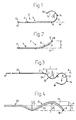
- FIGS. 1-2 schematically show the distal end region of a known stylet unit 2, a double stylet combination consisting of a flexible, tubular stylet shell 4 with a freely moving stylet wire 6 inside the shell's 4 channel.
- the distal end of the stylet shell 4 is designated 8
- the shell's proximal end is designated 10
- the stylet's 6 proximal end is designated 12.
- the internal stylet 6 has a pre-bent distal end section 14 which, in this case, is mainly semicircular with a radius of curvature ⁇ 1 and a short, straight stylet end portion 16 with a end stop ball 18 which prevents the end section 14 from being unintentionally drawn too far into the stylet shell 4 and minimizes the risk of a surrounding electrode cable wall (not shown here) being penetrated by the stylet end portion 16.
- the pre-bent distal end section 14 serves to impart a curved, J shape to the electrode cable's end section.
- the stylet unit is shown in FIG. 2 as it might appear when the internal stylet wire's 6 pre-bent distal section 14 is completely retracted into the stylet shell's 4 end section, so the stop ball 18 presses against the opening on the distal end 8 of the tubular stylet shell.
- the "single-bend" version of the stylet's distal end section 14 as shown in FIG. 1, a bend is produced in the stylet shell's 4 end section when the end section 14 is fully retracted. This means that the shell end 8 assumes a position corresponding to a lateral deviation L from the longitudinal axis A for the stylet unit's 2 straight section, shown to the left in FIGS. 1-2.
- the relative movement required between the shell 4 and the stylet wire 6 to deploy or retract the end section 14 into/out of the stylet shell 4 is usually achieved with a maneuvering and holding implement device (not shown) arranged at the proximal end 10 of the shell 4.
- the implement could be a holding device, for example, connected to the stylet shell 4, and a gripping device (handle), capable of moving the stylet in relation to the shell when the holding device is kept still.
- movement between the intemal stylet 6 and the surrounding shell 4 could be achieved by holding the stylet 6 still while moving the shell 4.
- FIGS. 3-4 show an internal stylet wire and a stylet unit according to the invention.
- the stylet unit devised as a double stylet combination, according to the invention is generally designated 20, whereas the displaceably arranged internal stylet wire in the shell's channel is designated 22.
- This internal stylet wire 22 is shown in FIG. 3 in a completely unloaded state, i.e. before the stylet has been retracted into the stylet unit's 20 tubular stylet shell 24.
- the internal stylet 22 has a pre-bent distal end section 14 of a known kind (cf. FIG. 1).
- This pre-bent semicircular end section 14 has a radius of curvature ⁇ 1 whose center of curvature B lies on the underside of the longitudinal axis A of the stylet wire's 22 straight stylet section between point C and the stylet's proximal end 12.
- the most distinguishing feature of the stylet wire according to the invention is that the stylet wire - over a region D - has a pre-shaped stylet section which comprises a pre-bent stylet section 26 with a radius of curvature ⁇ 2 and a semicircular transition section 28 between point E and point C. So the pre-bent stylet section 26 extends from point E to the flexion point F where the stylet's 22 pre-curved distal end section 14 begins.
- the stylet section's 26 radius of curvature is ⁇ 2 (from the center of curvature G) located on one side of the stylet wire 22, opposite the side where the pre-bent distal end section's 14 radius of curvature ⁇ 1 is located.
- the stylet section's 26 radius of curvature ⁇ 1 is on the stylet's left side whereas the end section's 14 radius of curvature ⁇ 1 is on the stylet's right side, seen on the FIGURE plane in FIG. 3.
- the stylet's 22 pre-shaped stylet section and the stylet's pre-bent distal end section 14 are on the same side of the longitudinal axis A as the straight section of the intemal stylet 22 located between the proximal end 12 and the point C.
- the radius of curvature's ⁇ 2 center of curvature G is on the longitudinal axis A, where as the radius of curvature's ⁇ 1 center of curvature B lies below said longitudinal axis A.
- the stylet's 22 pre-bent stylet section 26 could be devised so the centers of curvature G and B are on opposite sides of the longitudinal axis A.
- FIG. 4 shows how the tubular stylet shell 24 in the unloaded state is bent laterally by the internal stylet's 22 pre-bent stylet section 26 and by the pre-bent distal end section 14 when the two pre-bent parts of the stylet have been completely retracted into the tubular stylet shell 24, so the stop ball 18 presses against the opening of the shell's channel at the distal end 8 of the shell.
- retraction of the end section 14 and the stylet section 26 into the shell 24 is achieved by sliding the shell over both parts of the stylet. So the stylet shell 24 acquires a greatly flattened S shape with two regions, bent in opposite directions, on the shell's distal end section, viz.
- the stylet shell's 24 radius of curvature ⁇ ' 1 is mainly caused by the pre-bent end section's 14 radius of curvature ⁇ 1
- the shell's 24 radius of curvature ⁇ ' 2 is mainly caused by the pre-bent stylet section's 26 radius of curvature ⁇ 2 .
- the wavy, double-bend distal end area of the stylet shell 24 will, as a result of the stylet's 22 special conformation, display maximum lateral bending l 1 and l 2 , seen from the stylet unit's longitudinal axis A. But both the deviation l 1 and the deviation l 2 will be much less than the lateral deviation L (see FIG. 2) obtained with the use of a stylet shell 4 of the same kind as the stylet shell 24 used with the conventional type of internal stylet 6, according to FIG. 1. Even if the sum of the deviations l 1 and l 2 were as large as the lateral deviation L, according to FIG. 2, a maximum deviation from the longitudinal axis A, which is much less than the deviation L obtained with the known technic according to FIGS. 1-2.
- the deviation-reducing effect attained according to the invention is because the lateral deviations l 1 and l 2 are located on opposite sides of the center of longitudinal axis A.
- the stylet unit according to the invention is especially suitable for achieving a stiffening of an electrode cable (or lead) during the cable's advancement through a vein to a patient's heart and in concluding introduction a bending of a distal end section of the cable.
- the electrode cable it would obviously be advantageous for the electrode cable to be as straight as possible.
- the employed stylet unit must be as straight as possible during advancement, since it is the stylet unit which gives the electrode cable its stiffness.
- a stylet unit according to FIG. 4 would greatly simplify a physician's introduction of an electrode cable into a patient's heart compared to the use of a conventional stylet unit (according to FIG. 2) which imparts much greater lateral bending than the double stylet type of curved stylet unit, shown in FIG. 4, according to the present invention.
Abstract

Description
- The present invention relates to a stylet unit which can be inserted into a flexible component, such as a hollow electrode cable for a heart stimulator, a catheter or some other tubular instrument, with a narrow, longitudinal internal channel, to stiffen the flexible component and bend a distal end section of that component, said stylet unit constituting a double-stylet combination comprising a flexible, tubular stylet shell and an intemal stylet, displaceably arranged inside the shell's channel, with a pre-bent distal end section which can be set to a retracted position inside the stylet shell or to an exposed, projecting position outside the shell and whose radius of curvature is located on a first side of the intemal stylet.
- A channeled component of the aforementioned kind could e.g. be a tubular conductor used for stimulation in the human body. Such a channeled component could be devised to serve either as an implant or for removal from the body after a medical treatment has been performed.
- A stylet unit of the present kind is especially suitable for stiffening and guiding a hollow electrode cable for a heart stimulator during the electrode cable's advancement into a human heart and for anchoring a contact electrode (electrode head) on the distal end of the cable in a cavity of the heart. The introduction of such an electrode cable into the heart is usually through a suitable vein, and the contact electrode can be anchored in the right ventricle or atrium. The temporarily introduced stylet unit inside the hollow electrode cable extends through the cable's central channel from the cable's proximal end (which is subsequently connected to the heart stimulator) to its distal end on which the contact electrode is located.
- A stylet unit is especially suitable for anchoring a contact electrode in the heart's atrium, so an appropriate J shape can be imparted to the distal end section of the electrode cable, thereby facilitating introduction of the end section into the atrial auricle and anchoring of the contact electrode in the trabeculae of the atrial auricle. After the contact electrode has been anchored at the desired site in the heart, the stylet unit is completely removed from the heart.
- EP 0 381 810 A1 refers to a catheter tip attitude controlling guide wire for use with a catheter adapted to pass over the guide wire. The guide wire comprises an elongated wire-like cylindrical shaft having a distal end, a proximal end and an intermediate portion with a plurality of bends along its length. The intermediate portion is provided with an enclosing shell-like helical coil means. However, this coil means, which may comprise interconnected coils, is merely arranged to protect the intermediate wire portion, and the ends of the coil means are secured, typically by solder, to the ends of the guide wire shaft. Consequently, the guide wire shaft is not axially displaceably arranged inside the channel of the coil means.
- US A 3 757 768 refers to a spring guide-catheter comprising an inner wall portion defined by a helical spring, and an outer wall portion formed from a tube of plastic material. Inside the channel or lumen of the spring guide-catheter there is arranged a stylet wire for assisting in the manipulation and control of the spring guide-catheter. The stylet wire fits freely within said lumen and is freely movable axially with respect to the spring guide-catheter. However, this stylet wire is merely a one part single wire, and does not constitute any double stylet combination comprising a flexible, tubular stylet shell and an internal stylet wire displaceably arranged inside the shell's channel or lumen.
- US A 5 170 787 describes (see FIG. 2 in the document) a stylet unit, comprising a double stylet combination with a flexible, tubular shell containing a moveable intemal stylet in the shell's central channel. At the proximal end of this known stylet unit, there is a maneuvering handle with which the shell and the internal stylet can be moved in relation to each other to retract the stylet's pre-curved distal end section into the surrounding shell's distal end section or to deploy the pre-curved distal end section of the stylet outside the opening of the shell's end section into the central channel of the distal end section of the surrounding electrode cable in order to impart the desired curved shape to the distal end section..
- US A 4 136 703 shows another example of a stylet unit, devised as a double stylet combination, for an electrode cable. The stylet unit contains a pre-curved internal stylet in its distal end section.
- However, the types of prior art stylet units described in the two last-mentioned documents, i.e. double stylet combinations, are incapable of insuring that the stylet unit - and accordingly its surrounding electrode cable - attains a desired, largely straight configuration or conformation when the intemal stylet's pre-bent distal end section is retracted into the corresponding distal end section of the stylet shell.
- The primary object of the present invention is to achieve a new type of stylet unit with which it is possible to attain a much straighter, i.e. with less lateral bending, and much better shape for the distal end section of the stylet shell, with a stylet unit devised as a double stylet combination, when the pre-bent distal end section of the displaceable internal stylet wire has been fully retracted into the shell's channel and is surrounded by the stylet shell's enclosing distal end section.
- When the stylet's pre-bent distal end section has been exposed and deployed outside the opening of the stylet shell, it produces the desired bending of a corresponding section of the narrow, channel-equipped flexible component, which (as noted above) could be a hollow cable, a catheter or some other kind of elongate instrument posing some resistance to bending.
- An additional object of the invention is to achieve a stylet unit whose internal stylet wire has a very pronounced J or fish hook shape at its distal end section when this section is fully deployed outside the distal end section of the stylet shell.
- The design problems related to the aforementioned object are solved according to the present invention primarily when a stylet unit of the aforementioned kind has the distinguishing features set forth in the characterizing part of
patent claim 1. - Preferred embodiments and refinements of the stylet unit according to the invention can also have the distinguishing features set forth in the dependent claims.
- The main distinctive feature of the stylet unit according to the invention is that in the area located immediately before (viewed from the stylet unit's proximal end to its distal end) the pre-bent distal end section, the internal stylet is provided with a pre-shaped stylet section comprising a pre-bent stylet section whose radius of curvature is located on an opposite side ofthe stylet in relation to the said first side ofthe stylet.
- As a result of this combination of two diametrically opposed, pre-shaped curved stylet sections on the internal stylet wire, as proposed by the invention, the distal end section of the stylet unit's stylet shell displays a very stretched or flat S-shape when the internal stylet's double-bend end section has been completely retracted into the distal end section of a stylet shell.
- With a stylet unit devised in this manner, the shape of the distal section of the stylet shell has an undulating shape so flat, when the "double-bend" end section of the stylet wire is fully retracted into shell, that the maximum deviation from the midline of the shell's otherwise straight section becomes far less than with a traditional stylet design only utilizing a distal end section with pre-bending on one side.
- For the shape of the stylet shell to be as straight as possible, when the intemal stylet is fully retracted into the shell, it would also be appropriate for the part of the intemal stylet between the stylet's proximal end section and the stylet's pre-shaped stylet section, and the pre-bent distal end section, to have an essentially straight configuration in an unloaded state.
- So it would be desirable for the intemal stylet's pre-shaped stylet section and the stylet's pre-bent distal end section to lie on the same side of the longitudinal axis of said stylet part having an essentially straight configuration. Here, the centers of curvature for the stylet's pre-shaped stylet section and the stylet's pre-bent distal end section can then lie either on the same side of the said longitudinal axis or on opposite sides of this longitudinal axis. An optimally flat or longitudinally undulating S shape for the stylet shell, with the inner stylet retracted therein, is achieved when the stylet's pre-shaped stylet section and the stylet's pre-bent distal end section are located in a common plane which then preferably also includes the said the stylet part having an essentially straight configuration.
The stylet wire's pre-bent distal end section is suitably designed and arranged (in relation to the straight part of the stylet, between the stylet's proximal end and the pre-shaped stylet section) so that this look-like, pre-bent distal end section is touched by the longitudinal axis of said straight stylet part. - The invention will now be exemplified, described and further explained, referring to the enclosed drawings which depict in an elucidatory manner, but not to scale, a currently preferred embodiment of a stylet unit and its internal stylet wire according to the invention: Thus :
- FIG. 1 very schematically shows the relevant parts of a traditional stylet unit in which the internal stylet's pre-curved distal end section projects outside the stylet shell's opening;
- FIG. 2 shows the stylet unit, depicted in FIG. 1, when the stylet's pre-curved distal end section has been retracted into the tubular stylet shell's distal end section;
- FIG. 3 shows the internal stylet wire for a stylet unit, depicted in FIG. 4, according to the invention; and
- FIG. 4 shows a stylet unit according to the invention when the stylet wire's pre-bent distal end section has been completely retracted into the stylet shell.
- FIGS. 1-2 schematically show the distal end region of a known
stylet unit 2, a double stylet combination consisting of a flexible, tubular stylet shell 4 with a freely movingstylet wire 6 inside the shell's 4 channel. The distal end of the stylet shell 4 is designated 8, the shell's proximal end is designated 10 and the stylet's 6 proximal end is designated 12. As FIG. 1 shows, theinternal stylet 6 has a pre-bentdistal end section 14 which, in this case, is mainly semicircular with a radius of curvature ρ1 and a short, straight stylet end portion 16 with aend stop ball 18 which prevents theend section 14 from being unintentionally drawn too far into the stylet shell 4 and minimizes the risk of a surrounding electrode cable wall (not shown here) being penetrated by the stylet end portion 16. When thestylet unit 2 has been introduced into a longitudinally hollow electrode cable (not shown), the pre-bentdistal end section 14 serves to impart a curved, J shape to the electrode cable's end section. - The stylet unit is shown in FIG. 2 as it might appear when the internal stylet wire's 6
pre-bent distal section 14 is completely retracted into the stylet shell's 4 end section, so thestop ball 18 presses against the opening on thedistal end 8 of the tubular stylet shell. With the "single-bend" version of the stylet'sdistal end section 14, as shown in FIG. 1, a bend is produced in the stylet shell's 4 end section when theend section 14 is fully retracted. This means that theshell end 8 assumes a position corresponding to a lateral deviation L from the longitudinal axis A for the stylet unit's 2 straight section, shown to the left in FIGS. 1-2. - The relative movement required between the shell 4 and the
stylet wire 6 to deploy or retract theend section 14 into/out of the stylet shell 4 is usually achieved with a maneuvering and holding implement device (not shown) arranged at theproximal end 10 of the shell 4. Here, the implement could be a holding device, for example, connected to the stylet shell 4, and a gripping device (handle), capable of moving the stylet in relation to the shell when the holding device is kept still. Alternately, movement between theintemal stylet 6 and the surrounding shell 4 could be achieved by holding thestylet 6 still while moving the shell 4. - FIGS. 3-4 show an internal stylet wire and a stylet unit according to the invention.
- The stylet unit, devised as a double stylet combination, according to the invention is generally designated 20, whereas the displaceably arranged internal stylet wire in the shell's channel is designated 22. This
internal stylet wire 22 is shown in FIG. 3 in a completely unloaded state, i.e. before the stylet has been retracted into the stylet unit's 20tubular stylet shell 24. As shown in FIG. 3, theinternal stylet 22 has a pre-bentdistal end section 14 of a known kind (cf. FIG. 1). This pre-bentsemicircular end section 14 has a radius of curvature ρ1 whose center of curvature B lies on the underside of the longitudinal axis A of the stylet wire's 22 straight stylet section between point C and the stylet'sproximal end 12. The most distinguishing feature of the stylet wire according to the invention is that the stylet wire - over a region D - has a pre-shaped stylet section which comprises apre-bent stylet section 26 with a radius of curvature ρ2 and asemicircular transition section 28 between point E and point C. So thepre-bent stylet section 26 extends from point E to the flexion point F where the stylet's 22 pre-curveddistal end section 14 begins. - As shown in FIG. 3, the stylet section's 26 radius of curvature is ρ2 (from the center of curvature G) located on one side of the
stylet wire 22, opposite the side where the pre-bent distal end section's 14 radius of curvature ρ1 is located. Viewed along the stylet's 22 longitudinal axis from itsproximal end 12, via points C, E and F, to thestop ball 18, the stylet section's 26 radius of curvature ρ1 is on the stylet's left side whereas the end section's 14 radius of curvature ρ1 is on the stylet's right side, seen on the FIGURE plane in FIG. 3. - As FIG. 3 also shows, the stylet's 22 pre-shaped stylet section and the stylet's pre-bent
distal end section 14 are on the same side of the longitudinal axis A as the straight section of theintemal stylet 22 located between theproximal end 12 and the point C. - In the embodiment shown in FIG. 3, the radius of curvature's ρ2 center of curvature G is on the longitudinal axis A, where as the radius of curvature's ρ1 center of curvature B lies below said longitudinal axis A. However, the stylet's 22
pre-bent stylet section 26 could be devised so the centers of curvature G and B are on opposite sides of the longitudinal axis A. - Finally, FIG. 4 shows how the
tubular stylet shell 24 in the unloaded state is bent laterally by the internal stylet's 22pre-bent stylet section 26 and by the pre-bentdistal end section 14 when the two pre-bent parts of the stylet have been completely retracted into thetubular stylet shell 24, so thestop ball 18 presses against the opening of the shell's channel at thedistal end 8 of the shell. In practice, retraction of theend section 14 and thestylet section 26 into theshell 24 is achieved by sliding the shell over both parts of the stylet. So thestylet shell 24 acquires a greatly flattened S shape with two regions, bent in opposite directions, on the shell's distal end section, viz. a concluding bent section with a radius of curvature ρ'1 and a section before this, bent in the opposite direction ρ'2. The stylet shell's 24 radius of curvature ρ'1 is mainly caused by the pre-bent end section's 14 radius of curvature ρ1 , whereas the shell's 24 radius of curvature ρ'2 is mainly caused by the pre-bent stylet section's 26 radius of curvature ρ2. - The wavy, double-bend distal end area of the
stylet shell 24 will, as a result of the stylet's 22 special conformation, display maximum lateral bending l1 and l2, seen from the stylet unit's longitudinal axis A. But both the deviation l1 and the deviation l2 will be much less than the lateral deviation L (see FIG. 2) obtained with the use of a stylet shell 4 of the same kind as thestylet shell 24 used with the conventional type ofinternal stylet 6, according to FIG. 1. Even if the sum of the deviations l1 and l2 were as large as the lateral deviation L, according to FIG. 2, a maximum deviation from the longitudinal axis A, which is much less than the deviation L obtained with the known technic according to FIGS. 1-2. The deviation-reducing effect attained according to the invention is because the lateral deviations l1 and l2 are located on opposite sides of the center of longitudinal axis A. - As the above shows, the stylet unit according to the invention is especially suitable for achieving a stiffening of an electrode cable (or lead) during the cable's advancement through a vein to a patient's heart and in concluding introduction a bending of a distal end section of the cable. During the electrode cable's advancement through a vein, it would obviously be advantageous for the electrode cable to be as straight as possible. This means, in turn, that the employed stylet unit must be as straight as possible during advancement, since it is the stylet unit which gives the electrode cable its stiffness. So a stylet unit according to FIG. 4 would greatly simplify a physician's introduction of an electrode cable into a patient's heart compared to the use of a conventional stylet unit (according to FIG. 2) which imparts much greater lateral bending than the double stylet type of curved stylet unit, shown in FIG. 4, according to the present invention.
Claims (8)
- A stylet unit (20) which can be inserted into a flexible component, such as a hollow electrode cable, catheter or some other tubular instrument, with a narrow, longitudinal, internal channel, to stiffen the flexible component and bend a distal end section of that component, said stylet unit constituting of a double stylet combination comprising a flexible, tubular stylet shell (24) and an internal stylet (22), displaceably arranged inside the shell's channel, with a pre-bent distal end section (14) which can be set to a retracted position inside the shell or to a position projecting outside the shell and whose radius of curvature (ρ1) is located on a first side of the internal stylet (22), characterized in that the intemal stylet (22) is provided with a pre-shaped stylet section, in an area (D) located before the pre-bent distal end section (14), comprising a pre-bent stylet section (26) whose radius of curvature (ρ2) is located on an opposite second side of the stylet in relation to the said first side of the stylet (22).
- A stylet unit according to claim 1, characterized in that the part of the internal stylet (22) between a proximal end section of the stylet and the stylet's pre-shaped stylet section and the connected pre-bent distal end section (14) has an essentially straight configuration in an unloaded state.
- A stylet unit according to claim 2, characterized in that the stylet's (22) pre-shaped stylet section and the stylet's pre-bent distal end section (14) are on the same side of the longitudinal axis (A) of said stylet part having an essentially straight configuration.
- A stylet unit according to claim 3, characterized in that the centers of curvature (G, B) for the stylet's pre-shaped stylet section and the stylet's pre-bent end section (14) are on the same side of the said longitudinal axis (A).
- A stylet unit according to claim 3, characterized in that the centers of curvature (G, B) for the stylet's pre-shaped stylet section and the stylet's pre-bent end section (14) are on different sides of the said longitudinal axis (A).
- A stylet unit according to any of the preceding claims, characterized in that the radii of curvature (ρ2, ρ1) for the stylet's (22) pre-shaped stylet section and the stylet's pre-bent end section (14) are at least essentially constant for the respective section.
- A stylet unit according to any of claims 2-6, characterized in that the stylet's (22) pre-shaped stylet section and the stylet's pre-bent end section (14) are located in a common plane preferably also including said stylet part having an essentially straight configuration.
- A stylet unit according to any of claims 3-7, characterized in that the stylet's (22) pre-bent distal end section (14) is designed and arranged so that it is touched by the longitudinal axis A of said stylet part having an essentially straight configuration.
Applications Claiming Priority (2)
| Application Number | Priority Date | Filing Date | Title |
|---|---|---|---|
| SE9504334A SE9504334D0 (en) | 1995-12-04 | 1995-12-04 | Guidewire assembly |
| SE9504334 | 1995-12-04 |
Publications (3)
| Publication Number | Publication Date |
|---|---|
| EP0778044A2 true EP0778044A2 (en) | 1997-06-11 |
| EP0778044A3 EP0778044A3 (en) | 1997-07-09 |
| EP0778044B1 EP0778044B1 (en) | 2004-09-01 |
Family
ID=20400462
Family Applications (1)
| Application Number | Title | Priority Date | Filing Date |
|---|---|---|---|
| EP96850204A Expired - Lifetime EP0778044B1 (en) | 1995-12-04 | 1996-12-03 | Guidewire unit |
Country Status (5)
| Country | Link |
|---|---|
| US (1) | US5807339A (en) |
| EP (1) | EP0778044B1 (en) |
| JP (1) | JPH09173464A (en) |
| DE (1) | DE69633265T2 (en) |
| SE (1) | SE9504334D0 (en) |
Cited By (18)
| Publication number | Priority date | Publication date | Assignee | Title |
|---|---|---|---|---|
| DE19726093A1 (en) * | 1997-06-19 | 1998-12-24 | Lascor Gmbh | Flexible guide catheter |
| WO2000053250A1 (en) * | 1999-03-08 | 2000-09-14 | Baxter International Inc. | Directional guidewire |
| DE10132330A1 (en) * | 2001-07-02 | 2003-01-16 | Biotronik Mess & Therapieg | guidewire |
| EP1341578A1 (en) * | 2000-10-11 | 2003-09-10 | Cochlear Limited | Double stylet insertion tool for a cochlear implant electrode array |
| AU769303B2 (en) * | 1999-03-08 | 2004-01-22 | Endogad Research Pty Limited | Directional guidewire |
| WO2006023930A3 (en) * | 2004-08-23 | 2006-07-20 | Medtronic Inc | Novel distal portions for medical electrical leads |
| US7146227B2 (en) | 2000-10-04 | 2006-12-05 | Cochlear Limited | Combination stylet and straightening coating for a cochlear implant electrode array |
| US7272449B2 (en) | 2000-10-04 | 2007-09-18 | Cochlear Limited | Cochlear implant electrode array |
| EP1992383A1 (en) * | 2006-03-06 | 2008-11-19 | Terumo Kabushiki Kaisha | Guide wire |
| EP2135638A1 (en) | 2008-06-20 | 2009-12-23 | Ela Medical | Preformed mandrel for guiding a probe in contact with the wall of the septum |
| US7894916B2 (en) | 2000-10-17 | 2011-02-22 | Cochlear Limited | Insertion tool for a cochlear implant electrode array |
| US8133215B2 (en) | 2007-08-13 | 2012-03-13 | Cochlear Limited | Independently-manufactured drug delivery module and corresponding receptacle in an implantable medical device |
| US8219212B2 (en) | 2004-08-23 | 2012-07-10 | Medtronic, Inc. | Distal portions for medical electrical leads |
| US8401674B2 (en) | 2000-11-14 | 2013-03-19 | Cochlear Limited | Apparatus for delivery of pharmaceuticals to the cochlea |
| US8617097B2 (en) | 2010-05-24 | 2013-12-31 | Cochlear Limited | Drug-delivery accessory for an implantable medical device |
| US9089450B2 (en) | 2000-11-14 | 2015-07-28 | Cochlear Limited | Implantatable component having an accessible lumen and a drug release capsule for introduction into same |
| EP2967307A4 (en) * | 2013-03-15 | 2016-11-23 | Edward R Perez-Lizano | System and device for visualization of an enclosed space |
| US9849280B2 (en) | 2009-07-15 | 2017-12-26 | Sorin Crm Sas | Coronary venous pacing lead and anchoring screw system |
Families Citing this family (116)
| Publication number | Priority date | Publication date | Assignee | Title |
|---|---|---|---|---|
| US6197003B1 (en) * | 1997-08-15 | 2001-03-06 | University Of Iowa Research Foundation | Catheter advancing single-handed soft passer |
| JPH11192206A (en) * | 1997-10-29 | 1999-07-21 | Asahi Optical Co Ltd | Drainage tube retainer for endoscope |
| US6306132B1 (en) | 1999-06-17 | 2001-10-23 | Vivant Medical | Modular biopsy and microwave ablation needle delivery apparatus adapted to in situ assembly and method of use |
| US6722371B1 (en) | 2000-02-18 | 2004-04-20 | Thomas J. Fogarty | Device for accurately marking tissue |
| JP5090600B2 (en) * | 2000-02-18 | 2012-12-05 | トーマス ジェイ. フォガーティー, | Improved device for accurately marking tissues |
| US6776784B2 (en) | 2001-09-06 | 2004-08-17 | Core Medical, Inc. | Clip apparatus for closing septal defects and methods of use |
| US6702835B2 (en) | 2001-09-07 | 2004-03-09 | Core Medical, Inc. | Needle apparatus for closing septal defects and methods for using such apparatus |
| US20060052821A1 (en) | 2001-09-06 | 2006-03-09 | Ovalis, Inc. | Systems and methods for treating septal defects |
| US6878147B2 (en) | 2001-11-02 | 2005-04-12 | Vivant Medical, Inc. | High-strength microwave antenna assemblies |
| US7048722B2 (en) * | 2001-11-16 | 2006-05-23 | Radius International Limited Partnership | Catheter |
| US20040158229A1 (en) * | 2002-01-24 | 2004-08-12 | Quinn David G. | Catheter assembly and method of catheter insertion |
| EP1409061A4 (en) * | 2002-01-24 | 2006-08-23 | David G Quinn | Catheter and stylet assembly and method of catheter insertion |
| US7381205B2 (en) * | 2002-02-07 | 2008-06-03 | Carag Ag | Displacement device for a catheter |
| US6752767B2 (en) | 2002-04-16 | 2004-06-22 | Vivant Medical, Inc. | Localization element with energized tip |
| US7197363B2 (en) | 2002-04-16 | 2007-03-27 | Vivant Medical, Inc. | Microwave antenna having a curved configuration |
| US20030199949A1 (en) * | 2002-04-22 | 2003-10-23 | Xavier Pardo | Stylet for an implantable lead |
| US6944506B1 (en) | 2002-06-25 | 2005-09-13 | Pacesetter, Inc. | Stylet feature for resisting perforation of an implantable lead |
| JP2004041492A (en) * | 2002-07-12 | 2004-02-12 | Scitec Kk | Medical needle |
| US7953497B1 (en) | 2002-08-06 | 2011-05-31 | Boston Scientific Neuromodulation Corporation | Insertion stylet |
| US7419479B2 (en) * | 2002-11-15 | 2008-09-02 | Radius International Limited Partnership | Catheter |
| US6973352B1 (en) | 2002-12-05 | 2005-12-06 | Pacesetter, Inc. | Steerable cardiac pacing and sensing catheter and guidewire for implanting leads |
| US7311703B2 (en) | 2003-07-18 | 2007-12-25 | Vivant Medical, Inc. | Devices and methods for cooling microwave antennas |
| US20050159728A1 (en) * | 2004-01-15 | 2005-07-21 | Thomas Medical Products, Inc. | Steerable sheath |
| US9205261B2 (en) | 2004-09-08 | 2015-12-08 | The Board Of Trustees Of The Leland Stanford Junior University | Neurostimulation methods and systems |
| US20120277839A1 (en) | 2004-09-08 | 2012-11-01 | Kramer Jeffery M | Selective stimulation to modulate the sympathetic nervous system |
| US20060052856A1 (en) | 2004-09-08 | 2006-03-09 | Kim Daniel H | Stimulation components |
| WO2006092014A1 (en) * | 2005-03-04 | 2006-09-08 | Cathrx Ltd | A catheter handle and a catheter assembly including such a handle |
| US7379776B1 (en) | 2005-05-09 | 2008-05-27 | Pacesetter, Inc. | Stylet design |
| US9126011B2 (en) * | 2006-03-24 | 2015-09-08 | Merit Medical Systems, Inc. | Anti-clotting indwelling catheter |
| US8579936B2 (en) | 2005-07-05 | 2013-11-12 | ProMed, Inc. | Centering of delivery devices with respect to a septal defect |
| WO2007006055A2 (en) | 2005-07-06 | 2007-01-11 | Vascular Pathways Inc. | Intravenous catheter insertion device and method of use |
| JP4680007B2 (en) * | 2005-08-29 | 2011-05-11 | 日本ライフライン株式会社 | Stylet |
| US7846179B2 (en) | 2005-09-01 | 2010-12-07 | Ovalis, Inc. | Suture-based systems and methods for treating septal defects |
| US20070175482A1 (en) * | 2006-01-27 | 2007-08-02 | Ezc Medical Llc | Apparatus for introducing an airway tube into the trachea having visualization capability and methods of use |
| US8029457B2 (en) * | 2006-03-24 | 2011-10-04 | Aat Catheter Technologies, Llc | Indwelling catheter with anti-clotting features |
| EP2716322A3 (en) * | 2006-05-08 | 2014-05-21 | Cathrx Ltd | Method of fabricating a sheath for a catheter |
| US8068921B2 (en) | 2006-09-29 | 2011-11-29 | Vivant Medical, Inc. | Microwave antenna assembly and method of using the same |
| AU2007329253B2 (en) | 2006-12-06 | 2014-03-27 | Spinal Modulation, Inc. | Delivery devices, systems and methods for stimulating nerve tissue on multiple spinal levels |
| AU2007329252A1 (en) | 2006-12-06 | 2008-06-12 | Spinal Modulation, Inc. | Hard tissue anchors and delivery devices |
| WO2008070809A2 (en) | 2006-12-06 | 2008-06-12 | Spinal Modulation, Inc. | Implantable flexible circuit leads and methods of use |
| US9427570B2 (en) * | 2006-12-06 | 2016-08-30 | St. Jude Medical Luxembourg Holdings SMI S.A.R.L. (“SJM LUX SMI”) | Expandable stimulation leads and methods of use |
| AU2008210504B2 (en) * | 2007-01-29 | 2012-07-26 | Spinal Modulation, Inc. | Sutureless lead retention features |
| US20080208223A1 (en) * | 2007-02-26 | 2008-08-28 | Paul Edward Kraemer | Cable clamping device and method of its use |
| WO2008137956A2 (en) | 2007-05-07 | 2008-11-13 | Vascular Pathways, Inc. | Intravenous catheter insertion and blood sample devices and method of use |
| US9387308B2 (en) * | 2007-04-23 | 2016-07-12 | Cardioguidance Biomedical, Llc | Guidewire with adjustable stiffness |
| US20090018493A1 (en) * | 2007-07-10 | 2009-01-15 | Ash Stephen R | Implantable catheter assembly |
| US8292880B2 (en) | 2007-11-27 | 2012-10-23 | Vivant Medical, Inc. | Targeted cooling of deployable microwave antenna |
| WO2009089043A2 (en) * | 2008-01-09 | 2009-07-16 | Ezc Medical Llc. | Intubation systems and methods |
| US9833149B2 (en) * | 2008-03-18 | 2017-12-05 | Circa Scientific, Llc | Methods, apparatus and systems for facilitating introduction of shaped medical instruments into the body of a subject |
| WO2009117523A2 (en) | 2008-03-18 | 2009-09-24 | Circa Medical, Llc | Large surface area temperature sensing device |
| US9125562B2 (en) | 2009-07-01 | 2015-09-08 | Avinger, Inc. | Catheter-based off-axis optical coherence tomography imaging system |
| US8062316B2 (en) | 2008-04-23 | 2011-11-22 | Avinger, Inc. | Catheter system and method for boring through blocked vascular passages |
| US8100859B2 (en) * | 2008-06-24 | 2012-01-24 | Cook Medical Technologies Llc | Bent obturator |
| EP2373378B1 (en) | 2008-10-27 | 2017-04-26 | Spinal Modulation Inc. | Selective stimulation systems and signal parameters for medical conditions |
| US20100179562A1 (en) * | 2009-01-14 | 2010-07-15 | Linker Fred I | Stimulation leads, delivery systems and methods of use |
| AU2010229985B2 (en) | 2009-03-24 | 2015-09-17 | Spinal Modulation, Inc. | Pain management with stimulation subthreshold to paresthesia |
| JP5639580B2 (en) | 2009-04-14 | 2014-12-10 | テルモ株式会社 | Medical guidewire |
| WO2010129075A1 (en) | 2009-04-28 | 2010-11-11 | Avinger, Inc. | Guidewire support catheter |
| US9259569B2 (en) * | 2009-05-15 | 2016-02-16 | Daniel M. Brounstein | Methods, systems and devices for neuromodulating spinal anatomy |
| JP6101078B2 (en) | 2009-05-28 | 2017-03-29 | アビンガー・インコーポレイテッドAvinger, Inc. | Optical coherence tomography for bioimaging |
| EP2448502B1 (en) | 2009-07-01 | 2022-04-06 | Avinger, Inc. | Atherectomy catheter with laterally-displaceable tip |
| US9327110B2 (en) | 2009-10-27 | 2016-05-03 | St. Jude Medical Luxembourg Holdings SMI S.A.R.L. (“SJM LUX SMI”) | Devices, systems and methods for the targeted treatment of movement disorders |
| WO2011103530A2 (en) * | 2010-02-22 | 2011-08-25 | North Richard B | Percutaneous electrode |
| WO2011143233A2 (en) | 2010-05-10 | 2011-11-17 | Spinal Modulation, Inc. | Methods, systems and devices for reducing migration |
| US10384039B2 (en) | 2010-05-14 | 2019-08-20 | C. R. Bard, Inc. | Catheter insertion device including top-mounted advancement components |
| US9950139B2 (en) | 2010-05-14 | 2018-04-24 | C. R. Bard, Inc. | Catheter placement device including guidewire and catheter control elements |
| US11925779B2 (en) | 2010-05-14 | 2024-03-12 | C. R. Bard, Inc. | Catheter insertion device including top-mounted advancement components |
| US8932258B2 (en) | 2010-05-14 | 2015-01-13 | C. R. Bard, Inc. | Catheter placement device and method |
| US9872971B2 (en) | 2010-05-14 | 2018-01-23 | C. R. Bard, Inc. | Guidewire extension system for a catheter placement device |
| US11382653B2 (en) | 2010-07-01 | 2022-07-12 | Avinger, Inc. | Atherectomy catheter |
| WO2014039096A1 (en) * | 2012-09-06 | 2014-03-13 | Avinger, Inc. | Re-entry stylet for catheter |
| JP2013531542A (en) | 2010-07-01 | 2013-08-08 | アビンガー・インコーポレイテッド | An atherectomy catheter having a longitudinally movable drive shaft |
| JP4937391B2 (en) * | 2010-09-01 | 2012-05-23 | 日本ライフライン株式会社 | Intracardiac defibrillation catheter |
| US8690833B2 (en) | 2011-01-31 | 2014-04-08 | Vascular Pathways, Inc. | Intravenous catheter and insertion device with reduced blood spatter |
| US9901711B2 (en) * | 2011-02-16 | 2018-02-27 | Siemens Medical Solutions Usa, Inc. | Shape-controllable catheters and catheter system |
| CN103379937B (en) | 2011-02-25 | 2016-09-07 | C·R·巴德股份有限公司 | Medical component insertion device including retractible pin |
| WO2012145133A2 (en) | 2011-03-28 | 2012-10-26 | Avinger, Inc. | Occlusion-crossing devices, imaging, and atherectomy devices |
| US9949754B2 (en) | 2011-03-28 | 2018-04-24 | Avinger, Inc. | Occlusion-crossing devices |
| USD903101S1 (en) | 2011-05-13 | 2020-11-24 | C. R. Bard, Inc. | Catheter |
| JP6356604B2 (en) | 2011-10-17 | 2018-07-11 | アビンガー・インコーポレイテッドAvinger, Inc. | Atherotomy catheters and non-contact actuation mechanisms for catheters |
| US9345406B2 (en) | 2011-11-11 | 2016-05-24 | Avinger, Inc. | Occlusion-crossing devices, atherectomy devices, and imaging |
| US9557156B2 (en) | 2012-05-14 | 2017-01-31 | Avinger, Inc. | Optical coherence tomography with graded index fiber for biological imaging |
| EP2849660B1 (en) | 2012-05-14 | 2021-08-25 | Avinger, Inc. | Atherectomy catheter drive assemblies |
| WO2013172970A1 (en) | 2012-05-14 | 2013-11-21 | Avinger, Inc. | Atherectomy catheters with imaging |
| WO2015120146A1 (en) | 2014-02-06 | 2015-08-13 | Avinger, Inc. | Atherectomy catheters and occlusion crossing devices |
| US11284916B2 (en) | 2012-09-06 | 2022-03-29 | Avinger, Inc. | Atherectomy catheters and occlusion crossing devices |
| US9498247B2 (en) | 2014-02-06 | 2016-11-22 | Avinger, Inc. | Atherectomy catheters and occlusion crossing devices |
| EP2892448B1 (en) | 2012-09-06 | 2020-07-15 | Avinger, Inc. | Balloon atherectomy catheters with imaging |
| EP2922593B1 (en) * | 2012-11-21 | 2020-04-08 | Concert Medical, LLC | Preformed guidewire |
| WO2014120741A1 (en) | 2013-01-30 | 2014-08-07 | Vascular Pathways, Inc. | Systems and methods for venipuncture and catheter placement |
| EP2967507B1 (en) | 2013-03-15 | 2018-09-05 | Avinger, Inc. | Tissue collection device for catheter |
| US10932670B2 (en) | 2013-03-15 | 2021-03-02 | Avinger, Inc. | Optical pressure sensor assembly |
| US9854979B2 (en) | 2013-03-15 | 2018-01-02 | Avinger, Inc. | Chronic total occlusion crossing devices with imaging |
| US10130386B2 (en) | 2013-07-08 | 2018-11-20 | Avinger, Inc. | Identification of elastic lamina to guide interventional therapy |
| CN107106190B (en) | 2014-07-08 | 2020-02-28 | 阿维格公司 | High-speed chronic full-closure crossing device |
| US10232146B2 (en) | 2014-09-05 | 2019-03-19 | C. R. Bard, Inc. | Catheter insertion device including retractable needle |
| US10220189B2 (en) * | 2015-01-20 | 2019-03-05 | Selfex Devices, Inc. | High-torque guidewires and methods for making and using them |
| USD903100S1 (en) | 2015-05-01 | 2020-11-24 | C. R. Bard, Inc. | Catheter placement device |
| JP7016261B2 (en) | 2015-05-15 | 2022-02-21 | シー・アール・バード・インコーポレーテッド | Catheter indwelling device with extendable needle safety component |
| CA2992272A1 (en) | 2015-07-13 | 2017-01-19 | Avinger, Inc. | Micro-molded anamorphic reflector lens for image guided therapeutic/diagnostic catheters |
| EP3407777B1 (en) | 2016-01-25 | 2020-12-30 | Avinger, Inc. | Oct imaging catheter with lag correction |
| US10881851B2 (en) | 2016-03-18 | 2021-01-05 | Cardiac Interventions And Aviation Llc | Pacing guidewire |
| WO2017173370A1 (en) | 2016-04-01 | 2017-10-05 | Avinger, Inc. | Atherectomy catheter with serrated cutter |
| CN109475368A (en) | 2016-06-03 | 2019-03-15 | 阿维格公司 | Conduit device with detachable distal end |
| CN109414273B (en) | 2016-06-30 | 2023-02-17 | 阿维格公司 | Atherectomy catheter with shapeable distal tip |
| US10773076B2 (en) * | 2016-07-05 | 2020-09-15 | Wesley Robert Pedersen | Temporary pacing lead |
| JP7051821B2 (en) | 2016-09-12 | 2022-04-11 | シー・アール・バード・インコーポレーテッド | Blood control for catheter insertion device |
| CA3054969A1 (en) | 2017-03-01 | 2018-09-07 | C.R. Bard, Inc. | Catheter insertion device |
| EP3717057A1 (en) | 2017-11-30 | 2020-10-07 | Advanced Bionics AG | Slotted stiffening member for facilitating an insertion of an electrode lead into a cochlea of a patient |
| WO2019173641A1 (en) | 2018-03-07 | 2019-09-12 | Bard Access Systems, Inc. | Guidewire advancement and blood flashback systems for a medical device insertion system |
| USD921884S1 (en) | 2018-07-27 | 2021-06-08 | Bard Access Systems, Inc. | Catheter insertion device |
| BR112022003173A2 (en) | 2019-08-19 | 2022-05-17 | Becton Dickinson Co | Midline catheter placement device |
| CN114746033A (en) | 2019-10-18 | 2022-07-12 | 阿维格公司 | Obstruction crossing device |
| DE102020109730A1 (en) * | 2020-04-07 | 2021-10-07 | Marc Possover | Surgical application tool for implanting an electrode wire |
| WO2022040670A1 (en) * | 2020-08-17 | 2022-02-24 | Expanse Medical, Inc. | Transvenous pacing system |
| CA3154809A1 (en) | 2020-10-01 | 2022-04-07 | Benjamin HORST | Stylet with improved threadability |
Citations (4)
| Publication number | Priority date | Publication date | Assignee | Title |
|---|---|---|---|---|
| US3757768A (en) | 1972-04-07 | 1973-09-11 | Medical Evaluation Devices And | Manipulable spring guide-catheter and tube for intravenous feeding |
| US4136703A (en) | 1978-03-09 | 1979-01-30 | Vitatron Medical B.V. | Atrial lead and method of inserting same |
| EP0381810A1 (en) | 1989-02-07 | 1990-08-16 | Advanced Cardiovascular Systems, Inc. | Catheter tip attitude controlling guide wire |
| US5170787A (en) | 1990-03-30 | 1992-12-15 | Siemens Aktiengesellschaft | Device for positioning an electrode |
Family Cites Families (6)
| Publication number | Priority date | Publication date | Assignee | Title |
|---|---|---|---|---|
| US4643716A (en) * | 1984-09-26 | 1987-02-17 | The Kendall Company | Multi-size ureteral stent |
| US5179961A (en) * | 1989-04-13 | 1993-01-19 | Littleford Philip O | Catheter guiding and positioning method |
| DE3931350A1 (en) * | 1989-09-20 | 1991-03-28 | Kaltenbach Martin | GUIDE SLEEVE FOR IMPORTING CATHETERS |
| US5109830A (en) * | 1990-04-10 | 1992-05-05 | Candela Laser Corporation | Apparatus for navigation of body cavities |
| US5125395A (en) * | 1990-09-12 | 1992-06-30 | Adair Edwin Lloyd | Deflectable sheath for optical catheter |
| CA2176149C (en) * | 1993-11-10 | 2001-02-27 | Richard S. Jaraczewski | Electrode array catheter |
-
1995
- 1995-12-04 SE SE9504334A patent/SE9504334D0/en unknown
-
1996
- 1996-11-29 US US08/758,521 patent/US5807339A/en not_active Expired - Lifetime
- 1996-12-03 DE DE69633265T patent/DE69633265T2/en not_active Expired - Fee Related
- 1996-12-03 EP EP96850204A patent/EP0778044B1/en not_active Expired - Lifetime
- 1996-12-04 JP JP8324314A patent/JPH09173464A/en active Pending
Patent Citations (4)
| Publication number | Priority date | Publication date | Assignee | Title |
|---|---|---|---|---|
| US3757768A (en) | 1972-04-07 | 1973-09-11 | Medical Evaluation Devices And | Manipulable spring guide-catheter and tube for intravenous feeding |
| US4136703A (en) | 1978-03-09 | 1979-01-30 | Vitatron Medical B.V. | Atrial lead and method of inserting same |
| EP0381810A1 (en) | 1989-02-07 | 1990-08-16 | Advanced Cardiovascular Systems, Inc. | Catheter tip attitude controlling guide wire |
| US5170787A (en) | 1990-03-30 | 1992-12-15 | Siemens Aktiengesellschaft | Device for positioning an electrode |
Cited By (33)
| Publication number | Priority date | Publication date | Assignee | Title |
|---|---|---|---|---|
| DE19726093A1 (en) * | 1997-06-19 | 1998-12-24 | Lascor Gmbh | Flexible guide catheter |
| WO2000053250A1 (en) * | 1999-03-08 | 2000-09-14 | Baxter International Inc. | Directional guidewire |
| AU769303B2 (en) * | 1999-03-08 | 2004-01-22 | Endogad Research Pty Limited | Directional guidewire |
| US7272449B2 (en) | 2000-10-04 | 2007-09-18 | Cochlear Limited | Cochlear implant electrode array |
| US8265773B2 (en) | 2000-10-04 | 2012-09-11 | Cochlear Limited | Electrode assembly having a flexible tip |
| US7983767B2 (en) | 2000-10-04 | 2011-07-19 | Cochlear Limited | Cochlear implant electrode array |
| US7822487B2 (en) | 2000-10-04 | 2010-10-26 | Cochlear Limited | Combination stylet and sheath for an electrode array |
| US7146227B2 (en) | 2000-10-04 | 2006-12-05 | Cochlear Limited | Combination stylet and straightening coating for a cochlear implant electrode array |
| US7974711B2 (en) | 2000-10-11 | 2011-07-05 | Cochlear Limited | Double stylet insertion tool for a cochlear implant electrode array |
| US7269461B2 (en) | 2000-10-11 | 2007-09-11 | Cochlear Limited | Double stylet insertion tool for a cochlear implant electrode array |
| EP1341578A4 (en) * | 2000-10-11 | 2004-03-03 | Cochlear Ltd | Double stylet insertion tool for a cochlear implant electrode array |
| EP1341578A1 (en) * | 2000-10-11 | 2003-09-10 | Cochlear Limited | Double stylet insertion tool for a cochlear implant electrode array |
| US7894916B2 (en) | 2000-10-17 | 2011-02-22 | Cochlear Limited | Insertion tool for a cochlear implant electrode array |
| US9623221B2 (en) | 2000-11-14 | 2017-04-18 | Cochlear Limited | Apparatus for delivery of pharmaceuticals to the cochlea |
| US9089450B2 (en) | 2000-11-14 | 2015-07-28 | Cochlear Limited | Implantatable component having an accessible lumen and a drug release capsule for introduction into same |
| US8401674B2 (en) | 2000-11-14 | 2013-03-19 | Cochlear Limited | Apparatus for delivery of pharmaceuticals to the cochlea |
| DE10132330A1 (en) * | 2001-07-02 | 2003-01-16 | Biotronik Mess & Therapieg | guidewire |
| US8219212B2 (en) | 2004-08-23 | 2012-07-10 | Medtronic, Inc. | Distal portions for medical electrical leads |
| WO2006023930A3 (en) * | 2004-08-23 | 2006-07-20 | Medtronic Inc | Novel distal portions for medical electrical leads |
| US8353849B2 (en) | 2006-03-06 | 2013-01-15 | Terumo Kabushiki Kaisha | Guide wire |
| EP1992383A1 (en) * | 2006-03-06 | 2008-11-19 | Terumo Kabushiki Kaisha | Guide wire |
| EP1992383A4 (en) * | 2006-03-06 | 2009-04-08 | Terumo Corp | Guide wire |
| US8708932B2 (en) | 2006-03-06 | 2014-04-29 | Terumo Kabushiki Kaisha | Guide wire |
| US20080306468A1 (en) * | 2006-03-06 | 2008-12-11 | Terumo Kabushiki Kaisha | Guide Wire |
| US8133215B2 (en) | 2007-08-13 | 2012-03-13 | Cochlear Limited | Independently-manufactured drug delivery module and corresponding receptacle in an implantable medical device |
| EP2135638A1 (en) | 2008-06-20 | 2009-12-23 | Ela Medical | Preformed mandrel for guiding a probe in contact with the wall of the septum |
| US10071228B2 (en) | 2008-06-20 | 2018-09-11 | Sorin Crm Sas | Preformed stylet for guiding a lead to contact the septum |
| US9849280B2 (en) | 2009-07-15 | 2017-12-26 | Sorin Crm Sas | Coronary venous pacing lead and anchoring screw system |
| US8617097B2 (en) | 2010-05-24 | 2013-12-31 | Cochlear Limited | Drug-delivery accessory for an implantable medical device |
| US9101732B2 (en) | 2010-05-24 | 2015-08-11 | Cochlear Limited | Drug-delivery accessory for an implantable medical device |
| EP2967307A4 (en) * | 2013-03-15 | 2016-11-23 | Edward R Perez-Lizano | System and device for visualization of an enclosed space |
| US10368726B2 (en) | 2013-03-15 | 2019-08-06 | Edward R. Perez-Lizano | Intubation device capable of bi-directional distal deflection and temporary proximal, shaping for laryngoscopy, tracheoscopy, and bronchoscopy |
| US11617498B2 (en) | 2013-03-15 | 2023-04-04 | Edward R. Perez-Lizano | Intubation device capable of bi-directional distal deflection and temporary proximal shaping for laryngoscopy, tracheoscopy, and bronchoscopy |
Also Published As
| Publication number | Publication date |
|---|---|
| SE9504334D0 (en) | 1995-12-04 |
| EP0778044A3 (en) | 1997-07-09 |
| DE69633265D1 (en) | 2004-10-07 |
| US5807339A (en) | 1998-09-15 |
| JPH09173464A (en) | 1997-07-08 |
| EP0778044B1 (en) | 2004-09-01 |
| DE69633265T2 (en) | 2005-08-11 |
Similar Documents
| Publication | Publication Date | Title |
|---|---|---|
| EP0778044B1 (en) | Guidewire unit | |
| EP0778043B1 (en) | Guide wire unit with internal guide wire of shape memory alloy | |
| US5396902A (en) | Steerable stylet and manipulative handle assembly | |
| US5662119A (en) | Steerable stylet and manipulative handle assembly | |
| US4796642A (en) | Pacing lead stylet | |
| EP1317303B1 (en) | Steerable stylet with enhanced torsional transfer strength | |
| EP0773037B1 (en) | Guide wire unit | |
| EP1781363B1 (en) | A steerable catheter | |
| US5944689A (en) | Variable curve electrophysiology catheter | |
| US7747334B2 (en) | Left ventricular lead shapes | |
| US6728579B1 (en) | “Medical electrode lead” | |
| US5556425A (en) | Esophageal/stomach placement electrode | |
| EP0023410A1 (en) | Neural electrode lead | |
| US5674271A (en) | Catheter with steerable stylet | |
| US5423879A (en) | Controllable electrode device for in vivo tissue stimulation |
Legal Events
| Date | Code | Title | Description |
|---|---|---|---|
| PUAI | Public reference made under article 153(3) epc to a published international application that has entered the european phase |
Free format text: ORIGINAL CODE: 0009012 |
|
| PUAL | Search report despatched |
Free format text: ORIGINAL CODE: 0009013 |
|
| AK | Designated contracting states |
Kind code of ref document: A2 Designated state(s): DE ES FR GB IT NL |
|
| AK | Designated contracting states |
Kind code of ref document: A3 Designated state(s): DE ES FR GB IT NL |
|
| 17P | Request for examination filed |
Effective date: 19980107 |
|
| RAP1 | Party data changed (applicant data changed or rights of an application transferred) |
Owner name: ST. JUDE MEDICAL AB |
|
| GRAP | Despatch of communication of intention to grant a patent |
Free format text: ORIGINAL CODE: EPIDOSNIGR1 |
|
| GRAS | Grant fee paid |
Free format text: ORIGINAL CODE: EPIDOSNIGR3 |
|
| GRAA | (expected) grant |
Free format text: ORIGINAL CODE: 0009210 |
|
| AK | Designated contracting states |
Kind code of ref document: B1 Designated state(s): DE ES FR GB IT NL |
|
| PG25 | Lapsed in a contracting state [announced via postgrant information from national office to epo] |
Ref country code: NL Free format text: LAPSE BECAUSE OF FAILURE TO SUBMIT A TRANSLATION OF THE DESCRIPTION OR TO PAY THE FEE WITHIN THE PRESCRIBED TIME-LIMIT Effective date: 20040901 |
|
| REG | Reference to a national code |
Ref country code: GB Ref legal event code: FG4D |
|
| REF | Corresponds to: |
Ref document number: 69633265 Country of ref document: DE Date of ref document: 20041007 Kind code of ref document: P |
|
| PGFP | Annual fee paid to national office [announced via postgrant information from national office to epo] |
Ref country code: FR Payment date: 20041130 Year of fee payment: 9 |
|
| PG25 | Lapsed in a contracting state [announced via postgrant information from national office to epo] |
Ref country code: GB Free format text: LAPSE BECAUSE OF NON-PAYMENT OF DUE FEES Effective date: 20041203 |
|
| PG25 | Lapsed in a contracting state [announced via postgrant information from national office to epo] |
Ref country code: ES Free format text: LAPSE BECAUSE OF FAILURE TO SUBMIT A TRANSLATION OF THE DESCRIPTION OR TO PAY THE FEE WITHIN THE PRESCRIBED TIME-LIMIT Effective date: 20041212 |
|
| NLV1 | Nl: lapsed or annulled due to failure to fulfill the requirements of art. 29p and 29m of the patents act | ||
| ET | Fr: translation filed | ||
| PLBE | No opposition filed within time limit |
Free format text: ORIGINAL CODE: 0009261 |
|
| STAA | Information on the status of an ep patent application or granted ep patent |
Free format text: STATUS: NO OPPOSITION FILED WITHIN TIME LIMIT |
|
| GBPC | Gb: european patent ceased through non-payment of renewal fee |
Effective date: 20041203 |
|
| 26N | No opposition filed |
Effective date: 20050602 |
|
| PG25 | Lapsed in a contracting state [announced via postgrant information from national office to epo] |
Ref country code: IT Free format text: LAPSE BECAUSE OF NON-PAYMENT OF DUE FEES Effective date: 20051203 |
|
| PG25 | Lapsed in a contracting state [announced via postgrant information from national office to epo] |
Ref country code: FR Free format text: LAPSE BECAUSE OF NON-PAYMENT OF DUE FEES Effective date: 20060831 |
|
| REG | Reference to a national code |
Ref country code: FR Ref legal event code: ST Effective date: 20060831 |
|
| PGFP | Annual fee paid to national office [announced via postgrant information from national office to epo] |
Ref country code: DE Payment date: 20061219 Year of fee payment: 11 |
|
| PG25 | Lapsed in a contracting state [announced via postgrant information from national office to epo] |
Ref country code: DE Free format text: LAPSE BECAUSE OF NON-PAYMENT OF DUE FEES Effective date: 20080701 |