EP0778035B1 - Ventilator system - Google Patents
Ventilator system Download PDFInfo
- Publication number
- EP0778035B1 EP0778035B1 EP96115981A EP96115981A EP0778035B1 EP 0778035 B1 EP0778035 B1 EP 0778035B1 EP 96115981 A EP96115981 A EP 96115981A EP 96115981 A EP96115981 A EP 96115981A EP 0778035 B1 EP0778035 B1 EP 0778035B1
- Authority
- EP
- European Patent Office
- Prior art keywords
- line
- gas
- pressure
- expiratory
- inspiratory
- Prior art date
- Legal status (The legal status is an assumption and is not a legal conclusion. Google has not performed a legal analysis and makes no representation as to the accuracy of the status listed.)
- Expired - Lifetime
Links
Images

Classifications
-
- A—HUMAN NECESSITIES
- A61—MEDICAL OR VETERINARY SCIENCE; HYGIENE
- A61M—DEVICES FOR INTRODUCING MEDIA INTO, OR ONTO, THE BODY; DEVICES FOR TRANSDUCING BODY MEDIA OR FOR TAKING MEDIA FROM THE BODY; DEVICES FOR PRODUCING OR ENDING SLEEP OR STUPOR
- A61M16/00—Devices for influencing the respiratory system of patients by gas treatment, e.g. mouth-to-mouth respiration; Tracheal tubes
-
- A—HUMAN NECESSITIES
- A61—MEDICAL OR VETERINARY SCIENCE; HYGIENE
- A61B—DIAGNOSIS; SURGERY; IDENTIFICATION
- A61B5/00—Measuring for diagnostic purposes; Identification of persons
- A61B5/08—Detecting, measuring or recording devices for evaluating the respiratory organs
-
- A—HUMAN NECESSITIES
- A61—MEDICAL OR VETERINARY SCIENCE; HYGIENE
- A61M—DEVICES FOR INTRODUCING MEDIA INTO, OR ONTO, THE BODY; DEVICES FOR TRANSDUCING BODY MEDIA OR FOR TAKING MEDIA FROM THE BODY; DEVICES FOR PRODUCING OR ENDING SLEEP OR STUPOR
- A61M16/00—Devices for influencing the respiratory system of patients by gas treatment, e.g. mouth-to-mouth respiration; Tracheal tubes
- A61M16/04—Tracheal tubes
- A61M16/0402—Special features for tracheal tubes not otherwise provided for
- A61M16/042—Special features for tracheal tubes not otherwise provided for with separate conduits for in-and expiration gas, e.g. for limited dead volume
-
- A—HUMAN NECESSITIES
- A61—MEDICAL OR VETERINARY SCIENCE; HYGIENE
- A61B—DIAGNOSIS; SURGERY; IDENTIFICATION
- A61B5/00—Measuring for diagnostic purposes; Identification of persons
- A61B5/08—Detecting, measuring or recording devices for evaluating the respiratory organs
- A61B5/082—Evaluation by breath analysis, e.g. determination of the chemical composition of exhaled breath
-
- A—HUMAN NECESSITIES
- A61—MEDICAL OR VETERINARY SCIENCE; HYGIENE
- A61M—DEVICES FOR INTRODUCING MEDIA INTO, OR ONTO, THE BODY; DEVICES FOR TRANSDUCING BODY MEDIA OR FOR TAKING MEDIA FROM THE BODY; DEVICES FOR PRODUCING OR ENDING SLEEP OR STUPOR
- A61M16/00—Devices for influencing the respiratory system of patients by gas treatment, e.g. mouth-to-mouth respiration; Tracheal tubes
- A61M16/0003—Accessories therefor, e.g. sensors, vibrators, negative pressure
- A61M2016/0015—Accessories therefor, e.g. sensors, vibrators, negative pressure inhalation detectors
- A61M2016/0018—Accessories therefor, e.g. sensors, vibrators, negative pressure inhalation detectors electrical
- A61M2016/0021—Accessories therefor, e.g. sensors, vibrators, negative pressure inhalation detectors electrical with a proportional output signal, e.g. from a thermistor
-
- A—HUMAN NECESSITIES
- A61—MEDICAL OR VETERINARY SCIENCE; HYGIENE
- A61M—DEVICES FOR INTRODUCING MEDIA INTO, OR ONTO, THE BODY; DEVICES FOR TRANSDUCING BODY MEDIA OR FOR TAKING MEDIA FROM THE BODY; DEVICES FOR PRODUCING OR ENDING SLEEP OR STUPOR
- A61M16/00—Devices for influencing the respiratory system of patients by gas treatment, e.g. mouth-to-mouth respiration; Tracheal tubes
- A61M16/0003—Accessories therefor, e.g. sensors, vibrators, negative pressure
- A61M2016/0027—Accessories therefor, e.g. sensors, vibrators, negative pressure pressure meter
-
- A—HUMAN NECESSITIES
- A61—MEDICAL OR VETERINARY SCIENCE; HYGIENE
- A61M—DEVICES FOR INTRODUCING MEDIA INTO, OR ONTO, THE BODY; DEVICES FOR TRANSDUCING BODY MEDIA OR FOR TAKING MEDIA FROM THE BODY; DEVICES FOR PRODUCING OR ENDING SLEEP OR STUPOR
- A61M25/00—Catheters; Hollow probes
- A61M2025/0001—Catheters; Hollow probes for pressure measurement
- A61M2025/0003—Catheters; Hollow probes for pressure measurement having an additional lumen transmitting fluid pressure to the outside for measurement
Definitions
- the present invention relates to a method, for use with a ventilator system, for measuring pressure in a lung system during respirator treatment in which gas is carried to the lung system during inspiration via a first separate gas line and carried away from the lung system during expiration via a second separate gas line.
- the present invention also relates to a ventilator system comprising an inspiratory line, an expiratory line, a connector device, devised for placement at least in part in a patient's trachea, facing the carina, in order to connect the patient to the ventilator system, an inspiratory pressure meter, arranged to sense pressure in the inspiratory line .an expiratory pressure meter, arranged to sense pressurce in the expiratory line.
- One such ventilator system is described in WO-91/19526 and comprises a ventilator to which an inspiratory line and an expiratory line are connected.
- the inspiratory line and the expiratory line are attached, in turn, via a Y-piece to which a tracheal tube is also attached.
- the tracheal tube is intended for insertion into a patient's trachea in order to carry breathing gas to/from the patient's lungs.
- An inspiratory pressure meter is arranged in the ventilator unit to sense pressure in the ventilator system's inspiratory section and an expiratory pressure meter for sensing the pressure in the ventilator system's expiratory section.
- US-A-4,265,237 describes a ventilator system in which a special pressure measurement tube is inserted into the tracheal tube to measure pressure in the lower part of same. If the pressure measurement tube is inserted all the way down to the carina, pressure can be measured there with good accuracy. However, blockage of the pressure measurement tube by secretions and other materials formed in the patient's lungs and lower airways is a problem which can occur in this type of measurement. So this procedure is very unreliable.
- One object of the present invention is to solve the problems in known systems and achieve a ventilator system in which pressure measurements in the lungs can be performed simply and safely and with accurate results.
- This object is achieved in accordance with the invention in that the pressure in the lung system is measured during inspiration by measurement of pressure in the second separate gas line and/or pressure in the lung system is measured during expiration by measurement of pressure in the first separate gas line.
- SE-B-430 213 describes a ventilator system with two ventilator units.
- One of the ventilator units is set up as an ordinary ventilator, i.e. with inspiratory and expiratory lines connected to a common tracheal tube.
- the second ventilator unit has a separate supply line arranged inside the tracheal tube.
- breathing gas can be supplied, via the supply line, from the second ventilator unit, and gas can be carried away from the patient via the tracheal tube and expiratory line.
- this ventilator system is devised with a pressure measurement tube, like the one described above, to measure pressure in the carina.
- a ventilator system is achieved in accordance with the invention when the ventilator system according to the preamble is devised so the connector device comprises a first gas line, connected to the inspiratory line, and a second gas line, connected to the expiratory line, said gas lines being arranged so gas from the inspiratory valve flows through the inspiratory line and the first gas line towards the patient's trachea and gas from the patient flows through the second gas line and expiratory line towards the expiratory valve whereby gas only flows through the gas lines in one direction, and the expiratory pressure meter is adapted to measure pressure in the expiratory line during inspiration and the inspiratory pressure meter is adapted to measure pressure in the inspiratory line during expiration, whereby pressure in the patient's lungs is measurable.
- FIG. 1 shows the lower part of a patient's trachea 2. It opens onto the carina 4 from which the main bronchi 6A, 6B lead down into the lungs.
- a tracheal tube 8 is in the trachea 2 and affixed with a cuff 10.
- the cuff 10 is inflatable and prevents gas from passing through the trachea around the tracheal tube 8.
- the tracheal tube 8 has a first gas line 12, through which breathing gas is supplied to the patient's lungs during inspiration, and a second gas line 14, through which breathing gas is carried away from the patient's lungs during expiration.
- the first gas line 12 is connected to an inspiratory line 16.
- the inspiratory line 16 is connected to an inspiratory valve 18 which regulates the supply of breathing gas to the inspiratory line 16.
- a flow meter 20 is arranged to measure the flow of breathing gas from the inspiratory valve 18, and an inspiratory pressure meter 22 is arranged to measure pressure in the inspiratory line 16.
- the second gas line 14 is connected to an expiratory line 24 which, in turn, is connected to an expiratory valve 26.
- the expiratory valve 26 regulates the flow of gas from the patient's lungs and/or pressure in the expiratory line 24 in the end phase of expiration.
- a second flow meter 28 is arranged in the expiratory line 24 to measure the flow of breathing gas
- an expiratory pressure meter 30 is arranged to measure pressure in the expiratory line 24.
- the inspiratory valve 18, the first flow meter 20, the inspiratory pressure meter 22, the expiratory valve 26, the second flow meter 28 and the expiratory pressure meter 30 can all be arranged in a ventilator unit (not shown).
- a ventilator unit could be e.g. a Servo Ventilator 300, Siemens-Elema AB, Solna, Sweden.
- the ventilator unit can also consist of a ventilator unit according to the previously cited document, WO 91/19526 (Servo Ventilator 900 C, Siemens-Elema AB).
- the unique features of the invention are that gas to/from the patient passes through completely separate gas lines 12, 14 and, particularly, that pressure at the carina is measured with the expiratory pressure meter 30 during inspiration and vice-versa.
- pressure at the carina 4 can be measured with much greater accuracy than hitherto.
- no calculation program is needed to determine compensation for the fall in pressure etc. in the tracheal tube.
- inspiration when breathing gas is supplied via the inspiratory line 16 and the first gas line 12, no gas flows in the second gas line 14 and the expiratory line 24.
- the expiratory pressure meter 30 measures pressure at the carina 4, since there is no fall in pressure in the expiratory line 24 and the second gas line 14.
- a small flow is permissible in the second gas line 14, as long as the fall in pressure which then develops there is negligible. Any fall in pressure can be measured with good accuracy when the flow is supplied in the first gas line 12, and pressure is measured in the second gas line 14.
- the tracheal tube 8 with the first gas line 12 and the second gas line 14 can be devised in a plurality of ways, as shown in the tracheal tube cross-sections in FIGS. 2A, 2B and 2C.
- FIG. 2A shows the first gas line 12 arranged inside the second gas line 14.
- the first gas line 12 can also be arranged parallel to and alongside the second gas line 14 (FIG. 2B) or integrated into the second gas line 14 (FIG. 2C). Additional embodiments of the tracheal tube 8, with two separate gas lines 12, 14, can be simply achieved.
- the embodiment with separate gas lines 12, 14 also makes possible simpler pressure triggering in spontaneous breathing. Since the pressure meters 22, 30 measure pressure at the carina 4, any attempt at spontaneous breathing by the patient will be detected in the form of a fall in pressure at the carina 4. An inspiration can then be immediately supplied to the patient. In the corresponding manner, any attempt at expiration by the patient is quickly detected as an increase in pressure in the carina 4, and an expiration can then be triggered in a simpler manner than hitherto.
- the trachea normally forms a dead space, i.e. gas which is rebreathed at the start of an inspiration.
- the entire tracheal tube forms a dead space to an intubated patient.
- Another advantage of the separate administration and removal of breathing gas is that the system minimizes the dead space.
- the pressure meters 22, 30 can be simply checked against each other if pressure readings during inspiratory and expiratory pauses respectively, when no gas flows through any of the line 12, 14, 16, 24, are compared.
- a continuous basic flow of gas is then usually supplied via the inspiratory line 16. Flow is affected when the patient attempts to inhale, and an inspiration is triggered when flow has been affected to a sufficient degree.
- the system is devised in a specific manner described in greater detail in comments on FIG. 3.
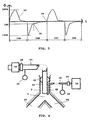
- FIG. 3 is a flow and time diagram showing a breathing curve 32.
- the breathing curve 32 covers two breathing cycles, a first inspiration 34A, a first expiration 34B, a second inspiration 34C and a second expiration 34D.
- Peak values for inspiratory flows and expiratory flows were set at 100%. They can be measured from breathing cycle to breathing cycle.
- the second flow meter measures flow during expiration.
- flow drops to a pre-defined percentage of the peak value for flow a weak basic flow of breathing gas is activated from the inspiratory valve. In this instance, 10% of the peak value for flow during the current expiratory 34B was used as the defined percentage.
- the patient will then be able to trigger an inspiration based on flow measurement.
- measured flow indicates a pre-defined inspiratory effort by the patient, as shown at point 38, the ventilator system is activated to supply an inspiration.
- the basic flow supplied is small, and the fall in pressure in the second gas line 14 is therefore also small, so the pressure reading obtained by the expiratory pressure meter 30 can be used for relatively accurate determination of e.g. PEEP.
- a weighted value between the pressure measured by the inspiratory pressure meter 22 and the pressure measured by the expiratory pressure meter 30 can be used to attain greater accuracy.
- FIG. 4 shows an alternative embodiment of the ventilator system according to the invention.
- Components which can be identical have the same designations as in FIG. 1. So they do not need to described again.
- the major difference between the ventilator system according to FIG. 4 and the ventilator system according to FIG. 1 is that the ventilator in FIG. 4 has a separate tracheal tube 40, with only one gas channel, inserted into the patient's trachea 2 to carry away expired breathing gas in expiration. Gas supplied to the patient during inspiration is instead carried through a tracheotomy connector 42 to the patient's airway 2.
- the tracheal tube 40 can be made relatively short and even avoid, in principle, passing the patient's vocal cords and damaging same.
Landscapes
- Health & Medical Sciences (AREA)
- Life Sciences & Earth Sciences (AREA)
- Pulmonology (AREA)
- General Health & Medical Sciences (AREA)
- Veterinary Medicine (AREA)
- Biomedical Technology (AREA)
- Heart & Thoracic Surgery (AREA)
- Public Health (AREA)
- Engineering & Computer Science (AREA)
- Animal Behavior & Ethology (AREA)
- Emergency Medicine (AREA)
- Hematology (AREA)
- Anesthesiology (AREA)
- Physiology (AREA)
- Physics & Mathematics (AREA)
- Biophysics (AREA)
- Pathology (AREA)
- Medical Informatics (AREA)
- Molecular Biology (AREA)
- Surgery (AREA)
- Measurement Of The Respiration, Hearing Ability, Form, And Blood Characteristics Of Living Organisms (AREA)
- Respiratory Apparatuses And Protective Means (AREA)
Description
Claims (7)
- A ventilator system comprising an inspiratory line (16), an inspiratory valve (18) which regulates the supply of breathing gas to the inspiratory line (16), an expiratory line (24), an expiratory valve (26) which regulates the flow of gas from the expiratory line (24), a connector device (8, 12, 14; 40, 42) devised for placement at least in part in a patient's trachea, facing the carina, in order to connect the patient to the ventilator system, an inspiratory pressure meter (22), arranged to sense pressure in the inspiratory line (16) and an expiratory pressure meter (30) arranged to sense pressure in the expiratory line (24), characterized in that the connector device (8, 12, 14; 40, 42) comprises a first gas line (12; 42), connected to the inspiratory line (16), and a second gas line (14; 40), connected to the expiratory line (24), said gas lines (12, 14; 40, 42) being arranged so gas from the inspiratory valve (18) flows through the inspiratory line (16) and the first gas line (12; 42) towards the patient's trachea and gas from the patient flows through the second gas line (14; 40) and the expiratory line (24) towards the expiratory valve (26), whereby gas only flows through the gas lines (12, 14; 40, 42) in one direction, and the expiratory pressure meter (30) is adapted to measure pressure in the expiratory line (24) during inspiration and the inspiratory pressure meter is adapted to measure pressure in the inspiratory line (16) during expiration, whereby pressure in the patient's lung is measurable.
- A ventilator system according to claim 1, characterized in that the first gas line (12; 42) has a smaller cross-section than the second gas line (14; 40).
- A ventilator system according to claim 1 or 2, characterized in that the connector device (8) is a tracheal tube.
- A ventilator system according to claim 3, characterized in that the first gas line (12) is arranged inside the second gas line (14).
- A ventilator system according to claim 4, characterized in that the first gas line (12) is arranged alongside and parallel to the second gas line (14).
- A ventilator system according to claim 1 or 2, characterized in that the first gas line (42) consists of a tracheotomy connector, and the second gas line (40) consists of a tracheal tube.
- A ventilator system according to any of claims 1-6, characterized in that there is a valve system (18), connected to the inspiratory line (16) to supply a pre-defined flow of gas through the inspiratory line (16), a first flow meter (20), arranged to measure the flow of gas in the inspiratory line (16), and a second flow meter (28), arranged to measure the flow of gas in the expiratory line (24), said valve system (18) being devised to supply a pre-defined continuous flow of gas, during at least a latter part of an expiratory phase when the flow measured by the second flow meter (28) has dropped below a threshold value, said threshold value preferably consisting of a pre-defined percentage of a peak value for flow measured by the second flow meter (28) during the expiratory phase.
Applications Claiming Priority (2)
| Application Number | Priority Date | Filing Date | Title |
|---|---|---|---|
| SE9504313A SE9504313L (en) | 1995-12-01 | 1995-12-01 | Method for pressure measurement in fan systems by means of two separate gas lines and one fan system |
| SE9504313 | 1995-12-01 |
Publications (2)
| Publication Number | Publication Date |
|---|---|
| EP0778035A1 EP0778035A1 (en) | 1997-06-11 |
| EP0778035B1 true EP0778035B1 (en) | 2003-07-16 |
Family
ID=20400444
Family Applications (1)
| Application Number | Title | Priority Date | Filing Date |
|---|---|---|---|
| EP96115981A Expired - Lifetime EP0778035B1 (en) | 1995-12-01 | 1996-10-04 | Ventilator system |
Country Status (5)
| Country | Link |
|---|---|
| US (1) | US5740796A (en) |
| EP (1) | EP0778035B1 (en) |
| JP (1) | JP3793299B2 (en) |
| DE (1) | DE69629092T2 (en) |
| SE (1) | SE9504313L (en) |
Cited By (13)
| Publication number | Priority date | Publication date | Assignee | Title |
|---|---|---|---|---|
| US8136527B2 (en) | 2003-08-18 | 2012-03-20 | Breathe Technologies, Inc. | Method and device for non-invasive ventilation with nasal interface |
| US8381729B2 (en) | 2003-06-18 | 2013-02-26 | Breathe Technologies, Inc. | Methods and devices for minimally invasive respiratory support |
| US8418694B2 (en) | 2003-08-11 | 2013-04-16 | Breathe Technologies, Inc. | Systems, methods and apparatus for respiratory support of a patient |
| US8567399B2 (en) | 2007-09-26 | 2013-10-29 | Breathe Technologies, Inc. | Methods and devices for providing inspiratory and expiratory flow relief during ventilation therapy |
| US8677999B2 (en) | 2008-08-22 | 2014-03-25 | Breathe Technologies, Inc. | Methods and devices for providing mechanical ventilation with an open airway interface |
| US8770193B2 (en) | 2008-04-18 | 2014-07-08 | Breathe Technologies, Inc. | Methods and devices for sensing respiration and controlling ventilator functions |
| US8776793B2 (en) | 2008-04-18 | 2014-07-15 | Breathe Technologies, Inc. | Methods and devices for sensing respiration and controlling ventilator functions |
| US8925545B2 (en) | 2004-02-04 | 2015-01-06 | Breathe Technologies, Inc. | Methods and devices for treating sleep apnea |
| US8939152B2 (en) | 2010-09-30 | 2015-01-27 | Breathe Technologies, Inc. | Methods, systems and devices for humidifying a respiratory tract |
| US8955518B2 (en) | 2003-06-18 | 2015-02-17 | Breathe Technologies, Inc. | Methods, systems and devices for improving ventilation in a lung area |
| US8985099B2 (en) | 2006-05-18 | 2015-03-24 | Breathe Technologies, Inc. | Tracheostoma spacer, tracheotomy method, and device for inserting a tracheostoma spacer |
| US9132250B2 (en) | 2009-09-03 | 2015-09-15 | Breathe Technologies, Inc. | Methods, systems and devices for non-invasive ventilation including a non-sealing ventilation interface with an entrainment port and/or pressure feature |
| US9180270B2 (en) | 2009-04-02 | 2015-11-10 | Breathe Technologies, Inc. | Methods, systems and devices for non-invasive open ventilation with gas delivery nozzles within an outer tube |
Families Citing this family (69)
| Publication number | Priority date | Publication date | Assignee | Title |
|---|---|---|---|---|
| JP3023263B2 (en) | 1993-09-03 | 2000-03-21 | キヤノン株式会社 | Recording device |
| JP3372671B2 (en) | 1994-09-14 | 2003-02-04 | キヤノン株式会社 | Method and apparatus for manufacturing color filter |
| US6155252A (en) * | 1995-03-17 | 2000-12-05 | Board Of Regents, The University Of Texas System | Method and apparatus for directing air flow within an intubated patient |
| US6463930B2 (en) | 1995-12-08 | 2002-10-15 | James W. Biondi | System for automatically weaning a patient from a ventilator, and method thereof |
| US6158432A (en) | 1995-12-08 | 2000-12-12 | Cardiopulmonary Corporation | Ventilator control system and method |
| AUPO163896A0 (en) | 1996-08-14 | 1996-09-05 | Resmed Limited | Determination of respiratory airflow |
| US5881717A (en) * | 1997-03-14 | 1999-03-16 | Nellcor Puritan Bennett Incorporated | System and method for adjustable disconnection sensitivity for disconnection and occlusion detection in a patient ventilator |
| JP3495930B2 (en) * | 1997-12-09 | 2004-02-09 | キヤノン株式会社 | Ink-jet adsorbent, ink holding container provided with an adsorbing member using the adsorbent, and ink supply system provided with an adsorbing member |
| US5896854A (en) * | 1998-05-04 | 1999-04-27 | Valley Inspired Products, Llc | Tracheal gas insufflation system |
| US6102038A (en) * | 1998-05-15 | 2000-08-15 | Pulmonetic Systems, Inc. | Exhalation valve for mechanical ventilator |
| JP3768689B2 (en) * | 1998-07-31 | 2006-04-19 | スズキ株式会社 | Ventilator |
| SE9802761D0 (en) * | 1998-08-19 | 1998-08-19 | Siemens Elema Ab | Bi-directional valve |
| US6102042A (en) | 1998-12-22 | 2000-08-15 | Respironics, Inc. | Insufflation system, attachment and method |
| US7431031B2 (en) * | 1998-12-22 | 2008-10-07 | Ric Investments, Llc | Insufflation system and method |
| SE9902709D0 (en) * | 1999-07-15 | 1999-07-15 | Siemens Elema Ab | Method for controlling an expiratory valve in a fan |
| CA2304292C (en) * | 2000-03-31 | 2009-01-13 | Joseph Fisher | An improved rebreathing circuit to set and stabalize end tidal and arterial pco2 despite varying levels of minute ventilation |
| US6355002B1 (en) * | 2000-05-22 | 2002-03-12 | Comedica Technologies Incorporated | Lung inflection point monitor apparatus and method |
| DE10123278C1 (en) * | 2001-05-10 | 2002-06-13 | Univ Hamburg | Breathing device used in intensive care or during anesthesia comprises a respirator, an outlet, an inhalation tube, a twin-channel endotracheal tube, flow meters, pressure meters, and an evaluation device |
| CN100532117C (en) * | 2002-06-04 | 2009-08-26 | 佳能株式会社 | Recording media for ink and manufacturing method thereof |
| SE0300734D0 (en) | 2003-03-18 | 2003-03-18 | Siemens Elema Ab | Method for determining an aspiration flow and an aspiration time and a device for aspirating a dead volume |
| DE10319384A1 (en) * | 2003-04-30 | 2004-11-18 | Universität Hamburg | Ventilation device with a double-lumen endotracheal tube |
| DE10337138A1 (en) * | 2003-08-11 | 2005-03-17 | Freitag, Lutz, Dr. | Method and arrangement for the respiratory assistance of a patient as well as tracheal prosthesis and catheter |
| AU2003903138A0 (en) * | 2003-06-20 | 2003-07-03 | Resmed Limited | Method and apparatus for improving the comfort of cpap |
| GB2413499A (en) * | 2004-04-28 | 2005-11-02 | Newcastle Upon Tyne Hospitals | Leak measurement around an uncuffed endo-tracheal tube |
| DE102004039711B3 (en) * | 2004-08-17 | 2006-05-11 | Dräger Medical AG & Co. KG | Method for automatic recording of pressure-volume curves in artificial respiration and apparatus for carrying out the method |
| WO2006053446A1 (en) * | 2004-11-19 | 2006-05-26 | Saturn Biomedical Systems Inc. | Secretion clearing ventilation catheter and airway management system |
| US8322339B2 (en) | 2006-09-01 | 2012-12-04 | Nellcor Puritan Bennett Llc | Method and system of detecting faults in a breathing assistance device |
| US20080142013A1 (en) * | 2006-09-11 | 2008-06-19 | Michael David Hallett | Exhaust Apparatus For Use in Administering Positive Pressure Therapy Through the Nose or Mouth |
| FR2914192B1 (en) * | 2007-04-02 | 2010-03-26 | Georges Boussignac | RESPIRATORY PROBE. |
| WO2008144589A1 (en) | 2007-05-18 | 2008-11-27 | Breathe Technologies, Inc. | Methods and devices for sensing respiration and providing ventilation therapy |
| US8251876B2 (en) | 2008-04-22 | 2012-08-28 | Hill-Rom Services, Inc. | Breathing exercise apparatus |
| US8905029B2 (en) | 2008-09-29 | 2014-12-09 | Covidien Lp | Airway system with carbon dioxide sensor for determining tracheal cuff inflation and technique for using the same |
| US8302602B2 (en) | 2008-09-30 | 2012-11-06 | Nellcor Puritan Bennett Llc | Breathing assistance system with multiple pressure sensors |
| CA2739435A1 (en) | 2008-10-01 | 2010-04-08 | Breathe Technologies, Inc. | Ventilator with biofeedback monitoring and control for improving patient activity and health |
| WO2010076712A1 (en) * | 2008-12-30 | 2010-07-08 | Koninklijke Philips Electronics, N.V. | System and respiration appliance for supporting the airway of a subject |
| WO2010076713A1 (en) * | 2008-12-30 | 2010-07-08 | Koninklijke Philips Electronics, N.V. | System and respiration appliance for supporting the airway of a subject |
| US9962512B2 (en) | 2009-04-02 | 2018-05-08 | Breathe Technologies, Inc. | Methods, systems and devices for non-invasive ventilation including a non-sealing ventilation interface with a free space nozzle feature |
| US8603003B2 (en) * | 2009-06-03 | 2013-12-10 | Covidien Lp | Trachea pressure determination method and device |
| US8473033B2 (en) * | 2009-06-17 | 2013-06-25 | Covidien Lp | Method and system for determining tracheal and location information for a tracheal tube |
| US8596277B2 (en) * | 2009-06-18 | 2013-12-03 | Covidien Lp | Tracheal tube with lumen for tracheal pressure measurement and technique for using the same |
| US8844534B2 (en) * | 2009-06-30 | 2014-09-30 | Covidien Lp | Tracheal tube with lumen for tracheal pressure measurement and technique for using the same |
| CA2774902C (en) | 2009-09-03 | 2017-01-03 | Breathe Technologies, Inc. | Methods, systems and devices for non-invasive ventilation including a non-sealing ventilation interface with an entrainment port and/or pressure feature |
| US20110144514A1 (en) * | 2009-12-16 | 2011-06-16 | Nellcor Puritan Bennett Llc | Tracheal Tube with Pressure Monitoring Lumen and Method for Using the Same |
| US9339208B2 (en) * | 2010-01-18 | 2016-05-17 | Covidien Lp | Tracheal tube with pressure monitoring lumen and method for using the same |
| US8397730B2 (en) | 2010-02-16 | 2013-03-19 | Covidien Lp | Tracheal tube adaptor and flaring jig |
| US20110284007A1 (en) * | 2010-05-21 | 2011-11-24 | Pierre Peron | Positive pressure device |
| GB201009666D0 (en) * | 2010-06-09 | 2010-07-21 | Univ Gent | Methods and systems for ventilating or compressing |
| JP5891226B2 (en) | 2010-08-16 | 2016-03-22 | ブリーズ・テクノロジーズ・インコーポレーテッド | Method, system and apparatus for providing ventilatory assistance using LOX |
| US8905030B2 (en) | 2011-03-31 | 2014-12-09 | Covidien Lp | Tracheal tube with connector insert |
| US9364624B2 (en) | 2011-12-07 | 2016-06-14 | Covidien Lp | Methods and systems for adaptive base flow |
| US9498589B2 (en) | 2011-12-31 | 2016-11-22 | Covidien Lp | Methods and systems for adaptive base flow and leak compensation |
| US9022031B2 (en) | 2012-01-31 | 2015-05-05 | Covidien Lp | Using estimated carinal pressure for feedback control of carinal pressure during ventilation |
| US9180271B2 (en) | 2012-03-05 | 2015-11-10 | Hill-Rom Services Pte. Ltd. | Respiratory therapy device having standard and oscillatory PEP with nebulizer |
| US8844526B2 (en) | 2012-03-30 | 2014-09-30 | Covidien Lp | Methods and systems for triggering with unknown base flow |
| US9492629B2 (en) | 2013-02-14 | 2016-11-15 | Covidien Lp | Methods and systems for ventilation with unknown exhalation flow and exhalation pressure |
| US9981096B2 (en) | 2013-03-13 | 2018-05-29 | Covidien Lp | Methods and systems for triggering with unknown inspiratory flow |
| EP3086831B1 (en) * | 2013-12-27 | 2020-09-23 | St. Michael's Hospital | System for providing ventilatory assist to a patient |
| ES2544026B1 (en) * | 2014-02-25 | 2016-05-31 | Medcom Flow S A | Device for continuous positive pressure |
| US9808591B2 (en) | 2014-08-15 | 2017-11-07 | Covidien Lp | Methods and systems for breath delivery synchronization |
| US9950129B2 (en) | 2014-10-27 | 2018-04-24 | Covidien Lp | Ventilation triggering using change-point detection |
| US9925346B2 (en) | 2015-01-20 | 2018-03-27 | Covidien Lp | Systems and methods for ventilation with unknown exhalation flow |
| US10245406B2 (en) | 2015-03-24 | 2019-04-02 | Ventec Life Systems, Inc. | Ventilator with integrated oxygen production |
| US11247015B2 (en) | 2015-03-24 | 2022-02-15 | Ventec Life Systems, Inc. | Ventilator with integrated oxygen production |
| JP6480598B2 (en) | 2015-04-02 | 2019-03-13 | ヒル−ロム サービシーズ プライヴェート リミテッド | Respirator manifold |
| US10773049B2 (en) | 2016-06-21 | 2020-09-15 | Ventec Life Systems, Inc. | Cough-assist systems with humidifier bypass |
| US10792449B2 (en) | 2017-10-03 | 2020-10-06 | Breathe Technologies, Inc. | Patient interface with integrated jet pump |
| CA3100163A1 (en) | 2018-05-13 | 2019-11-21 | Samir Saleh AHMAD | Portable medical ventilator system using portable oxygen concentrators |
| DE102020112504A1 (en) * | 2019-05-17 | 2020-11-19 | Gyrus Acmi, Inc. D/B/A Olympus Surgical Technologies America | SYSTEM FOR EVALUATING COLLATERAL VENTILATION |
| US11324954B2 (en) | 2019-06-28 | 2022-05-10 | Covidien Lp | Achieving smooth breathing by modified bilateral phrenic nerve pacing |
Family Cites Families (7)
| Publication number | Priority date | Publication date | Assignee | Title |
|---|---|---|---|---|
| DE2831313A1 (en) * | 1978-07-17 | 1980-02-07 | Draegerwerk Ag | DEVICE FOR SUPPORTING BREATHING AND / OR ARTIFICIAL VENTILATION |
| SE425595B (en) * | 1978-11-29 | 1982-10-18 | Siemens Elema Ab | DEVICE OF A RESPIRATORY DEVICE |
| SE430213B (en) * | 1981-03-10 | 1983-10-31 | Siemens Elema Ab | RESPIRATOR INTENDED TO BE CONNECTED TO THE HUMAN OR ANIMAL PATIENTS |
| DE3204110C2 (en) * | 1982-02-06 | 1984-08-02 | Gerhard Dr.med. 7800 Freiburg Meuret | Tracheal tube for artificial ventilation and respirator for connection to this tube |
| SE500550C2 (en) * | 1990-06-18 | 1994-07-11 | Siemens Elema Ab | Methods and apparatus for reducing gas re-breathing from the harmful space |
| DE4221931C1 (en) * | 1992-07-03 | 1993-07-08 | Harald Dr. 8521 Moehrendorf De Mang | |
| US5546935A (en) * | 1993-03-09 | 1996-08-20 | Medamicus, Inc. | Endotracheal tube mounted pressure transducer |
-
1995
- 1995-12-01 SE SE9504313A patent/SE9504313L/en unknown
-
1996
- 1996-10-04 EP EP96115981A patent/EP0778035B1/en not_active Expired - Lifetime
- 1996-10-04 DE DE69629092T patent/DE69629092T2/en not_active Expired - Fee Related
- 1996-11-06 US US08/743,737 patent/US5740796A/en not_active Expired - Fee Related
- 1996-11-29 JP JP32019596A patent/JP3793299B2/en not_active Expired - Fee Related
Cited By (18)
| Publication number | Priority date | Publication date | Assignee | Title |
|---|---|---|---|---|
| US8381729B2 (en) | 2003-06-18 | 2013-02-26 | Breathe Technologies, Inc. | Methods and devices for minimally invasive respiratory support |
| US8955518B2 (en) | 2003-06-18 | 2015-02-17 | Breathe Technologies, Inc. | Methods, systems and devices for improving ventilation in a lung area |
| US8418694B2 (en) | 2003-08-11 | 2013-04-16 | Breathe Technologies, Inc. | Systems, methods and apparatus for respiratory support of a patient |
| US8136527B2 (en) | 2003-08-18 | 2012-03-20 | Breathe Technologies, Inc. | Method and device for non-invasive ventilation with nasal interface |
| US8573219B2 (en) | 2003-08-18 | 2013-11-05 | Breathe Technologies, Inc. | Method and device for non-invasive ventilation with nasal interface |
| US8925545B2 (en) | 2004-02-04 | 2015-01-06 | Breathe Technologies, Inc. | Methods and devices for treating sleep apnea |
| US8985099B2 (en) | 2006-05-18 | 2015-03-24 | Breathe Technologies, Inc. | Tracheostoma spacer, tracheotomy method, and device for inserting a tracheostoma spacer |
| US8567399B2 (en) | 2007-09-26 | 2013-10-29 | Breathe Technologies, Inc. | Methods and devices for providing inspiratory and expiratory flow relief during ventilation therapy |
| US8770193B2 (en) | 2008-04-18 | 2014-07-08 | Breathe Technologies, Inc. | Methods and devices for sensing respiration and controlling ventilator functions |
| US8776793B2 (en) | 2008-04-18 | 2014-07-15 | Breathe Technologies, Inc. | Methods and devices for sensing respiration and controlling ventilator functions |
| US8677999B2 (en) | 2008-08-22 | 2014-03-25 | Breathe Technologies, Inc. | Methods and devices for providing mechanical ventilation with an open airway interface |
| US9180270B2 (en) | 2009-04-02 | 2015-11-10 | Breathe Technologies, Inc. | Methods, systems and devices for non-invasive open ventilation with gas delivery nozzles within an outer tube |
| US9227034B2 (en) | 2009-04-02 | 2016-01-05 | Beathe Technologies, Inc. | Methods, systems and devices for non-invasive open ventilation for treating airway obstructions |
| US10232136B2 (en) | 2009-04-02 | 2019-03-19 | Breathe Technologies, Inc. | Methods, systems and devices for non-invasive open ventilation for treating airway obstructions |
| US9132250B2 (en) | 2009-09-03 | 2015-09-15 | Breathe Technologies, Inc. | Methods, systems and devices for non-invasive ventilation including a non-sealing ventilation interface with an entrainment port and/or pressure feature |
| US10265486B2 (en) | 2009-09-03 | 2019-04-23 | Breathe Technologies, Inc. | Methods, systems and devices for non-invasive ventilation including a non-sealing ventilation interface with an entrainment port and/or pressure feature |
| US8939152B2 (en) | 2010-09-30 | 2015-01-27 | Breathe Technologies, Inc. | Methods, systems and devices for humidifying a respiratory tract |
| US9358358B2 (en) | 2010-09-30 | 2016-06-07 | Breathe Technologies, Inc. | Methods, systems and devices for humidifying a respiratory tract |
Also Published As
| Publication number | Publication date |
|---|---|
| DE69629092T2 (en) | 2004-04-22 |
| EP0778035A1 (en) | 1997-06-11 |
| SE9504313D0 (en) | 1995-12-01 |
| JPH09173455A (en) | 1997-07-08 |
| DE69629092D1 (en) | 2003-08-21 |
| SE504257C2 (en) | 1996-12-16 |
| SE9504313L (en) | 1996-12-16 |
| US5740796A (en) | 1998-04-21 |
| JP3793299B2 (en) | 2006-07-05 |
Similar Documents
| Publication | Publication Date | Title |
|---|---|---|
| EP0778035B1 (en) | Ventilator system | |
| EP0653183B1 (en) | Method by determination of the functional residual capacity of lungs and a ventilator device for the determination of the functional residual capacity | |
| EP0965356B1 (en) | A method for determining the volume of a tubing system and a breathing apparatus system | |
| EP0745402B1 (en) | Arrangement for determining an opening pressure for a lung system | |
| US5931162A (en) | Ventilator which allows spontaneous inhalation and expiration within a controlled breathing mode | |
| US7305988B2 (en) | Integrated ventilator nasal trigger and gas monitoring system | |
| US7487778B2 (en) | Tracheal catheter and prosthesis and method of respiratory support of a patient | |
| US8652065B2 (en) | Breathing transition detection | |
| US9259544B2 (en) | Pressure support system with machine delivered breaths | |
| Ishaaya et al. | Work of breathing after extubation | |
| US10137266B2 (en) | Patient-ventilator dyssynchrony detection | |
| NL8101088A (en) | DEVICE FOR MEASURING AT LEAST TWO PNEUMATIC LUNG PARAMETERS AND A MEASUREMENT METHOD FOR THIS. | |
| US5720277A (en) | Ventilator/Anaesthetic system with juxtaposed CO2 meter and expired gas flow meter | |
| US6599252B2 (en) | Method and apparatus for anatomical deadspace measurement | |
| US4300385A (en) | Method and apparatus for determining the alcohol content of a person's blood | |
| US7827981B2 (en) | Method for reducing the work of breathing | |
| JP2000005312A (en) | Method for controlling exhalation valve of respirator | |
| SE9702710L (en) | A method for determining the mechanical properties of the respiratory system of a patient breathing and a device for carrying out the procedure | |
| Lofaso et al. | Inaccuracy of tidal volume delivered by home mechanical ventilators | |
| EP0728493A1 (en) | Ventilator/anaesthetic system | |
| JP5695573B2 (en) | System and method for determination of functional residual capacity of a subject | |
| EP1076576B1 (en) | Tracheal gas insufflation system | |
| JPS61100231A (en) | Respiration monitor apparatus | |
| US9308338B2 (en) | Detection of dynamic hyperinflation in spontaneously breathing mechanically ventilated patients | |
| US20230414888A1 (en) | System for controlling and measuring oxygen delivery through a cpap adaptor |
Legal Events
| Date | Code | Title | Description |
|---|---|---|---|
| PUAI | Public reference made under article 153(3) epc to a published international application that has entered the european phase |
Free format text: ORIGINAL CODE: 0009012 |
|
| AK | Designated contracting states |
Kind code of ref document: A1 Designated state(s): CH DE ES FI FR GB IT LI NL |
|
| 17P | Request for examination filed |
Effective date: 19971006 |
|
| 17Q | First examination report despatched |
Effective date: 20000303 |
|
| GRAH | Despatch of communication of intention to grant a patent |
Free format text: ORIGINAL CODE: EPIDOS IGRA |
|
| RTI1 | Title (correction) |
Free format text: VENTILATOR SYSTEM |
|
| GRAH | Despatch of communication of intention to grant a patent |
Free format text: ORIGINAL CODE: EPIDOS IGRA |
|
| GRAA | (expected) grant |
Free format text: ORIGINAL CODE: 0009210 |
|
| AK | Designated contracting states |
Designated state(s): CH DE ES FI FR GB IT LI NL |
|
| PG25 | Lapsed in a contracting state [announced via postgrant information from national office to epo] |
Ref country code: NL Free format text: LAPSE BECAUSE OF FAILURE TO SUBMIT A TRANSLATION OF THE DESCRIPTION OR TO PAY THE FEE WITHIN THE PRESCRIBED TIME-LIMIT Effective date: 20030716 Ref country code: LI Free format text: LAPSE BECAUSE OF FAILURE TO SUBMIT A TRANSLATION OF THE DESCRIPTION OR TO PAY THE FEE WITHIN THE PRESCRIBED TIME-LIMIT Effective date: 20030716 Ref country code: IT Free format text: LAPSE BECAUSE OF FAILURE TO SUBMIT A TRANSLATION OF THE DESCRIPTION OR TO PAY THE FEE WITHIN THE PRESCRIBED TIME-LIMIT;WARNING: LAPSES OF ITALIAN PATENTS WITH EFFECTIVE DATE BEFORE 2007 MAY HAVE OCCURRED AT ANY TIME BEFORE 2007. THE CORRECT EFFECTIVE DATE MAY BE DIFFERENT FROM THE ONE RECORDED. Effective date: 20030716 Ref country code: FI Free format text: LAPSE BECAUSE OF FAILURE TO SUBMIT A TRANSLATION OF THE DESCRIPTION OR TO PAY THE FEE WITHIN THE PRESCRIBED TIME-LIMIT Effective date: 20030716 Ref country code: CH Free format text: LAPSE BECAUSE OF FAILURE TO SUBMIT A TRANSLATION OF THE DESCRIPTION OR TO PAY THE FEE WITHIN THE PRESCRIBED TIME-LIMIT Effective date: 20030716 |
|
| REG | Reference to a national code |
Ref country code: GB Ref legal event code: FG4D |
|
| REG | Reference to a national code |
Ref country code: CH Ref legal event code: EP |
|
| REF | Corresponds to: |
Ref document number: 69629092 Country of ref document: DE Date of ref document: 20030821 Kind code of ref document: P |
|
| PG25 | Lapsed in a contracting state [announced via postgrant information from national office to epo] |
Ref country code: GB Free format text: LAPSE BECAUSE OF NON-PAYMENT OF DUE FEES Effective date: 20031016 |
|
| PG25 | Lapsed in a contracting state [announced via postgrant information from national office to epo] |
Ref country code: ES Free format text: LAPSE BECAUSE OF FAILURE TO SUBMIT A TRANSLATION OF THE DESCRIPTION OR TO PAY THE FEE WITHIN THE PRESCRIBED TIME-LIMIT Effective date: 20031027 |
|
| NLV1 | Nl: lapsed or annulled due to failure to fulfill the requirements of art. 29p and 29m of the patents act | ||
| REG | Reference to a national code |
Ref country code: CH Ref legal event code: PL |
|
| ET | Fr: translation filed | ||
| PLBE | No opposition filed within time limit |
Free format text: ORIGINAL CODE: 0009261 |
|
| STAA | Information on the status of an ep patent application or granted ep patent |
Free format text: STATUS: NO OPPOSITION FILED WITHIN TIME LIMIT |
|
| GBPC | Gb: european patent ceased through non-payment of renewal fee |
Effective date: 20031016 |
|
| REG | Reference to a national code |
Ref country code: FR Ref legal event code: TP |
|
| 26N | No opposition filed |
Effective date: 20040419 |
|
| PGFP | Annual fee paid to national office [announced via postgrant information from national office to epo] |
Ref country code: DE Payment date: 20071023 Year of fee payment: 12 |
|
| PGFP | Annual fee paid to national office [announced via postgrant information from national office to epo] |
Ref country code: FR Payment date: 20080930 Year of fee payment: 13 |
|
| PG25 | Lapsed in a contracting state [announced via postgrant information from national office to epo] |
Ref country code: DE Free format text: LAPSE BECAUSE OF NON-PAYMENT OF DUE FEES Effective date: 20090501 |
|
| REG | Reference to a national code |
Ref country code: FR Ref legal event code: ST Effective date: 20100630 |
|
| PG25 | Lapsed in a contracting state [announced via postgrant information from national office to epo] |
Ref country code: FR Free format text: LAPSE BECAUSE OF NON-PAYMENT OF DUE FEES Effective date: 20091102 |