EP0776763A1 - Process for the production of lithographic printing plates - Google Patents
Process for the production of lithographic printing plates Download PDFInfo
- Publication number
- EP0776763A1 EP0776763A1 EP96119199A EP96119199A EP0776763A1 EP 0776763 A1 EP0776763 A1 EP 0776763A1 EP 96119199 A EP96119199 A EP 96119199A EP 96119199 A EP96119199 A EP 96119199A EP 0776763 A1 EP0776763 A1 EP 0776763A1
- Authority
- EP
- European Patent Office
- Prior art keywords
- plate
- image
- resin
- ink jet
- ink
- Prior art date
- Legal status (The legal status is an assumption and is not a legal conclusion. Google has not performed a legal analysis and makes no representation as to the accuracy of the status listed.)
- Granted
Links
Images


Classifications
-
- G—PHYSICS
- G03—PHOTOGRAPHY; CINEMATOGRAPHY; ANALOGOUS TECHNIQUES USING WAVES OTHER THAN OPTICAL WAVES; ELECTROGRAPHY; HOLOGRAPHY
- G03F—PHOTOMECHANICAL PRODUCTION OF TEXTURED OR PATTERNED SURFACES, e.g. FOR PRINTING, FOR PROCESSING OF SEMICONDUCTOR DEVICES; MATERIALS THEREFOR; ORIGINALS THEREFOR; APPARATUS SPECIALLY ADAPTED THEREFOR
- G03F7/00—Photomechanical, e.g. photolithographic, production of textured or patterned surfaces, e.g. printing surfaces; Materials therefor, e.g. comprising photoresists; Apparatus specially adapted therefor
- G03F7/20—Exposure; Apparatus therefor
- G03F7/2002—Exposure; Apparatus therefor with visible light or UV light, through an original having an opaque pattern on a transparent support, e.g. film printing, projection printing; by reflection of visible or UV light from an original such as a printed image
- G03F7/2014—Contact or film exposure of light sensitive plates such as lithographic plates or circuit boards, e.g. in a vacuum frame
- G03F7/2016—Contact mask being integral part of the photosensitive element and subject to destructive removal during post-exposure processing
- G03F7/2018—Masking pattern obtained by selective application of an ink or a toner, e.g. ink jet printing
-
- B—PERFORMING OPERATIONS; TRANSPORTING
- B41—PRINTING; LINING MACHINES; TYPEWRITERS; STAMPS
- B41C—PROCESSES FOR THE MANUFACTURE OR REPRODUCTION OF PRINTING SURFACES
- B41C1/00—Forme preparation
- B41C1/10—Forme preparation for lithographic printing; Master sheets for transferring a lithographic image to the forme
- B41C1/1066—Forme preparation for lithographic printing; Master sheets for transferring a lithographic image to the forme by spraying with powders, by using a nozzle, e.g. an ink jet system, by fusing a previously coated powder, e.g. with a laser
Definitions
- the present invention relates to a process for the fabrication of a lithographic printing plate using ink jet printing heads and techniques.
- the novel process involves the direct formation of a resinous image pattern on a lithographic plate employing digital image information and digitally driven printer heads.
- the invention is especially useful for the fabrication of large, commercial grade, high production run lithographic printing plates for offset printing.
- Lithography and offset printing methods have long been combined in a compatible marriage of great convenience for the printing industry for economical, high speed, high quality image duplication in small runs and large.
- Known art available to the industry for image transfer to a lithographic plate is voluminous but dominated by the photographic process wherein a hydrophilic plate is treated with a photosensitive coating, exposed via a film image and developed to produce a printable, oleophilic image on the plate.
- lithographic plates by photographic image transfer While preparing lithographic plates by photographic image transfer is relatively efficient and efficacious, it is a multi-step, indirect process of constrained flexibility.
- a photographically presensitized (PS) plate is prepared from a hydrophilically surface treated aluminum.
- a positive or negative film image of an original hard copy is prepared and the PS plate exposed to the film image, developed, washed and made ready for print operations. Any desired changes in the film image must be made by first changing the original hard copy and repeating the photographic process; hence, the constrained flexibility.
- the need for a lithographic plate fabricating process that obviates the above problems associated with the photographic process has long been recognized.
- Image forming by digital computer aided design of graphical material or text is well known.
- Electronically derived images of words or graphics presented on the CRT of a digital computer system can be edited and converted to final hard copy by direct printing with impact printers, laser printers or ink jet printers.
- This manner of printing or producing hard copy is extremely flexible and useful when print runs of no more than a few thousand are required but the print process is not feasible for large runs measured in the tens or hundreds of thousands of pieces.
- printing by lithographic plate is still the preferred process with such plates prepared by the process of photographic image transfer.
- digitized image information can be used in plate making wherein a film is made to express the image according to the image information digitization and an image is formed on the plate by exposure and development. While this method augments flexibility by permitting editing of a digitized image, the method does not overcome the problems associated with the photographic image transfer method of plate fabrication.
- United States Patent No. 4 833 486 discloses the use of an ink jet head to deposit a hot wax upon the surface of a lithographic plate.
- the hot wax solidifies upon contact with the plate, thus providing an instantaneous printing pattern. Plates prepared by this method are useful for very limited print runs of a few thousand pieces.
- a further drawback of the apparatus disclosed in the '486 patent is that it makes use of an ink jet medium which may be a wax.
- Wax is a soft material and will abrade with use under the conditions present for commercial offset printing. Even the so-called hard waxes will not provide the durability required for commercial printing runs of the order of 100,000 cycles. Moreover, waxes do not strongly bond to the printing plate surface, i.e., they prefer to remain on the surface, rather than to actively bond to the substrate.
- European Patent Application EP 0 503 621 A1 discloses a direct lithographic plate making system using an ink jet system to form an ink image on the plate by exposure treatment of the plate.
- a primary objective of the instant invention is to provide a process for the production of lithographic printing plates using ink jet printer heads and techniques to directly provide a printable image on the plate with good resolution and wearablity sufficient for large print runs.
- Another objective of the invention is to integrate the methods of the primary objective with digital computer information systems for digital image formation and digital control of the ink jet printer heads.
- a more specific objective of the invention is to create a printable resinous image on the lithographic plate using ink jet printing heads to describe the image on the plate surface with resin forming chemicals coupled with in situ polymerization of the chemicals.
- Yet a further object is to describe the resinous image on the printing plate using digitized control of the ink jet printing heads.
- the invention provides for a process for fabricating a printing plate, particularly a commercial lithographic or offset printing plate.
- the process utilizes ink jet liquid droplets from one or more printer heads to form an image upon the surface of the printing plate corresponding to digital information depicting the image as provided by a digital computer system which is in digital communication with the printer heads.
- the droplets from the printer head polymerize on the plate surface to form a printable image comprising a resin.
- the physical characteristics of the resin so formed are such as to provide a lithographic printing plate useful for extended print runs.
- the reactants which include monomers and initiators required to effect the polymerization may be precoated on the plate or deposited from one or more printing head in a manner designed to initiate polymerization upon deposition.
- Initiators may be chemical catalysts or electromagnetic radiation.
- the polymerization is carried out using at least one multi-functional reactant that produces a crosslinked resin alone or in combination with other reactants. However, uncrossliked resins are also useful.
- the invention comprises a method for producing a lithographic printing plate containing a printable resinous image.
- the method comprises depositing a liquid comprising at least one reactant of a resin producing reaction mixture onto the plate employing at least one printer head in a predetermined image-reproducing manner.
- the liquid is deposited on the plate in contact with remaining reactant(s) necessary to complete the mixture on the surface of said plate.
- the polymerization is completed on the plate under resin polymerization conditions whereby a lithographic plate containing a printable resinous image is produced.
- a suitable predetermined image-reproducing method for depositing the reactants onto the plate comprises
- the invention comprises a process for producing a printable lithographic printing plate by creating a hardened, solid resin image on the plate.
- the image is created from resin forming reactants, at least one of which is a liquid or dissolved in a solvent as deposited on the plate by an ink jet type printing head to precisely describe the image to be printed.
- reactants refers to polymerizable resin forming monomers and polymerization catalysts, initiators or intermediates, including any portion of the electromagnetic spectrum, air/oxygen, and the like.
- Monomers include one or more generally low molecular weight polymer, copolymer or terpolymer-forming chemical(s) or prepolymers such as oligomers capable of further polymerization into higher molecular weight solid resins. All the resin forming reactants are combined on the surface of a treated or untreated lithographic plate to form a complete resin-forming reaction mixture under conditions sufficient to convert the mixture to a resin.
- the resin so formed may comprise a cross-linked or linear polymer.
- the resin forming reaction mixture can be formed and polymerized on the surface of a treated or untreated plate by one or more of the following general methods:
- the image-forming layer is generally a hydrophobic layer and hydrophobic substances are deposited on such layer; such hydrophobic substances accept waterless or oleic-type inks. It is within the scope of the present invention, however, to coat the surface of a normally hydrophilic plate to render the surface hydrophobic. The present invention would then utilize hydrophilic compounds to form the image on the plate surface.
- the layer may be either a positive or negative photosensitive layer.
- the process of the invention utilizes ink jet fluids comprising hardenable materials that will harden and become bound to the surface of the printing plate, thus providing an image that will endure tens of thousands of printing runs.
- Suitable hardenable materials include polymers that will harden upon exposure to electromagnetic radiation, particularly ultraviolet light radiation or electron beam radiation.
- radiation-hardenable polymers include urethane-acrylate, epoxy-acrylate and polyester-acrylate oligomers.
- the radiation-hardenable polymer is an epoxy-acrylate oligomer.
- the hardenable material may be an adhesive which will harden upon exposure to the air, anaerobically or by contact with the metal of the plate.
- suitable examples of such adhesives include the cyanocrylates.
- the ink jet fluid may comprise a two-component epoxy resin ⁇ epoxy resin hardening agent system.
- suitable epoxy resins include Bisphenol A diglycidyl ethers of various molecular weights, cycloaliphatic epoxides with methyl tetrahydrophthalic anhydride or hexahydrophthalic anhydride, etc. (the typical flexibilizers and polyols may also be present, if desired).
- the preferred epoxy resin for the purposes of the present invention is the Bisphenol A diglycidyl ether type.
- the epoxy resin hardening agent may be an aliphatic, cycloapliphatic or aromatic amine such as diethylene triamine, triethylene tetramine, tetraethylene pentamine, methylene dianiline, metaphenylene diamine, polamides, and the like.
- the preferred epoxy resin hardening agent is a polyamide.
- Suitable monomers for the instant invention comprise bifunctional or polyfunctional monomers or prepolymers selected from the group consisting of epoxides, polyamines, alkyl and aryl isocyanates, polyols, acyl halides, formaldehyde, phenol, bis-phenol A, maleic anhydride, phthalic anhydride, acrylic acid, cyanoacrylate, methacrylic acid, styrene, vinyl toluene, alpha methyl styrene, vinyl chloride, vinylidene chloride, acrylonitrile, acrylamide, methyl and ethyl vinyl ether, vinyl acetate, vinyl alcohol/acetate, and esters and polyesters of acrylic acid and methacrylic acid.
- the radiation source to be used for hardening the polymer and bonding it to the printing plate surface will typically be a mercury vapor lamp where hardening by ultraviolet radiation is desired.
- a mercury vapor lamp will usually be of the medium pressure type (i.e. ⁇ 10 2 Torr); such lamps have lifetimes in excess of 5,000 hours and have efficient spectral output with two dominant UV bands at 365 and 366 nm.
- the radiation source will typically be an electron beam generator of the scanned beam type or linear cathode type. Regardless of which radiation source is chosen, it is desirable to choose the polymer type, radiation source, radiation dosage, exposure time, etc. such that the polymer will harden and bond to the printing plate surface in as short a time as is practicable.
- the process of the present invention involves the formation of an image derived from digitized computer information on the surface of a printing plate.
- the image is deposited on the plate in the form of ink jet droplets which in turn are deposited from an ink jet printing head.
- the printing head movable along "x" (horizontal) and “y” (vertical) axes, is mounted upon an assembly (table) which is also movable in the x-y plane.
- Drive mechanisms e.g. step motors, controlled by a computer, move the jet of the printing head along the "x" and "y” axes to position the ink jet droplets upon the plate surface.
- the table supporting the printing head is also movable in the x-y plane by means of drive mechanisms. The movement of the table provides for the printing of multiple pages upon large lithographic plates.
- the fluid medium dispensed by the ink jet printing head is caused to harden and bond to the printing plate surface upon contact therewith, or immediately thereafter.
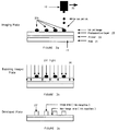
- Figure 1 depicts an ink jet printing head assembly for use with the apparatus of the present invention.
- the assembly is capable of producing lithographic plates of commercial quality since it is fast and accurate when depositing ink jet droplets.
- Raster Image Processing for lithographic ink jet processes, must be performed with large amounts of information in order to provide the high resolution required for commercially viable offset printing plates.
- Commercial plates require scanning a large plate surface and means for producing multiple pages as shown.
- Ink jet printing head 12 is often required to make subsequent scans in synchronization. This necessitates a very high degree of mechanical accuracy.
- printing head 12 is mounted on any x-y table 14 such as Opti-copy Imposer x-y table or IPM Platemaker x-y table.
- computer and control unit 11 provides digitally times "x" (horizontal), "y” (vertical ink jetting movement to print head 12 and planar x-y movement (shown by the "x" and “y” arrows in FIGURE 1) to table 14.
- the x-y movement of table 14 is accomplished by drive mechanisms (not shown) and the "x" and "y” ink jetting movement of printing head 12 are provided by drive mechanisms (e.g. step motors) 17 and 18, respectively.
- printing head 12 is subsequently moved to other positions on the surface of plate 15 in order to image subsequent pages 16b, 16c, etc.
- the imaging of the pages is not necessarily carried out in sequence. In fact, the pages are usually out of sequence, and may even be printed upside down with respect to adjacent pages.
- Ink jet printing head 12 has a nozzle plate with a plurality of nozzles (not shown).
- a reservoir disposed inside printing head 12 supplies the ink to the nozzles through a series of channels.
- the processor (CPU) of computer and control unit 11 supplies graphics and textual information to printing head 12. The higher the resolution, i.e. the greater the dots per inch, the more digital information is required to be stored and disseminated by the computer memory.
- FIGURES 2a and 2b The sequential schematic flow diagrams of a first process embodiment of the invention are shown in FIGURES 2a and 2b.
- Printing head assembly 10 moves (in the direction of arrow 30) past plate 15.
- Assembly 10 jets droplets 20a of an opaque fluid that deposit upon plate 15 to form the image mask.
- the plate is then decoated in a conventional plate processor.
- Image pattern 20a prevents the decoater chemical from reacting with the photosensitive layer underlying the image layer. Thus, the non-image area is decoated and becomes ink repellant.
- a printing plate comprised of a grained aluminum substrate overcoated with an organic photosensitive coating was employed in this Example.
- a solid or liquid ink jet ink was jetted on the surface of the plate to form the imaging pattern.
- the plate was then decoated with a plate processor such that the image pattern prevented the decoating chemical from reacting with the photosensitive layer underlying the image pattern and the non-image pattern area was decoated.
- the image area accepted the ink.
- the printing plate was coated with a clear film-forming acrylic binder which was alkali or alcohol soluble (other binders are also useful for the purposes of this invention, e.g. polyesters, polycarbonates, polystyrene, phenolics, polyurethanes, etc.
- binders are also useful for the purposes of this invention, e.g. polyesters, polycarbonates, polystyrene, phenolics, polyurethanes, etc.
- the ink jet printing head was filled with an ultraviolet light-curable printing ink which was then jetted onto the surface of the coated substrate to form an image pattern.
- the resultant plate was then exposed to ultraviolet light to harden the image pattern and was then developed in a conventional manner.
- Example 2 The coated plate of Example 2 is employed in this embodiment.
- the ink jet printing head is filled with a thermally-curable ink which is then jetted onto the surface of the plate.
- the plate is then heated to harden the image pattern and developed in a conventional manner.
- Example 2 The coated plate of Example 2 was employed in this embodiment.
- An ink jet printing head with two nozzles connected to separate ink reservoirs was used in this Example.
- the reservoirs were filled with an epoxy resin and an epoxy resin amine hardener.
- the printing head jetted a drop of each component at the same place on the plate surface where they mixed and reacted to form a single, hardened dot to form an image pattern.
- the resultant plate was then developed in a conventional manner.
- FIGURES 3a, 3b, and 3c are sequential schematic flow diagrams.
- the printing head assembly moves (in the direction of arrow 30) past plate 15.
- the assembly jets droplets 20b of an opaque fluid that deposit and form an image upon plate 15.
- the opaque fluid may be a printing ink or any opaque substance that will provide an image upon the plate surface.
- the plate is irradiated with ultraviolet light (arrows 26), as shown in FIGURE 3b.
- Those areas covered by opaque droplets 20b will mask the photosensitive 23 and the area radiated by the ultraviolet light will become developable.
- image areas 23' will remain, as shown in FIGURE 3c.
- Image areas 23' are ink receptive while the non-image areas are ink repellant, thus providing an offset plate.
- a positive plate was used.
- the plate comprised an aluminum base overcoated with primer and photosensitive layers, as taught in U.S. Patent No. 3,635,709.
- a solid ink jet ink was jetted upon the surface of a plate to form an image pattern.
- the plate was then exposed to ultraviolet light. During exposure, the image area blocked the ultraviolet light, thus leaving only the exposed photosensitive area to be photoreacted.
- the resultant plate was then developed in a conventional manner. When a conventional printing ink was rubbed on the plate surface, the unexposed image area accepted the ink.
- the offset plate fabricated by this method was found to be suitable for long printing runs.
- the printing plate of Example 5 was employed in this embodiment.
- the printing plate surface was covered with a thin layer of gum arabic to render the surface hydrophilic.
- a water-based ink jet ink was jetted upon the surface of the plate to form an image pattern, and the plate was thereafter exposed to ultraviolet light. During exposure, the image area blocked the ultraviolet light, thus leaving only the exposed photosensitive area to be photoreacted.
- the resultant plate was then developed in a conventional manner.
- the ink jet ink and photosensitive layers were washed away by the developer, leaving only unexposed photosensitive areas remaining on the plate. When an offset printing ink was rubbed on the plate, the remaining image area accepted the ink.
- the offset printing plate fabricated by this method was also suitable for long printing runs.
- a negative plate as described in U.S. Patent No. 4,171,974 was used.
- This plate comprised an aluminum base overcoated with a photosensitive layer.
- the printing plate surface was covered with a thin layer of gum arabic to render the surface hydrophilic.
- a water-based ink was jetted upon the surface of the plate to form an image pattern; the ink acted as a mask to block ultraviolet light during exposure.
- the unexposed photosensitive layer was removed by a developer such as that described in U.S. Patent No. 3,891,439, leaving the exposed area on the plate.
- a Toray Waterless positive plate was used.
- the plate consisted of four layers overcoated on an aluminum base: a transparent protecting film layer, silicone layer, photosensitive layer and a primer layer.
- the solid ink jet ink was jetted upon the surface of the plate to form an image pattern and the plate was then exposed to ultraviolet light. After exposure, the protective top film layer was manually removed, and the resultant plate was then developed, washed and dried in a conventional manner.
- the photosensitive layer in the image areas where the silicone layer was removed became ink receptive.
- Examples 9A-9B describe the printing platemaking process using an ink jet which contains reactants that directly react with the substrate.
- the substrate is aluminum having a grained aluminum surface or aluminum anodized with sulfuric acid or phosphoric acid.
- the anodized aluminum may contain an interlayer such as a silicated interlayer.
- the ink jet contacts the surface of the substrate and reacts with the substrate to form a hardened resinous image pattern.
- the ink jet printing head is filled with an ink such as Thread Locker available from Locktite, Inc.
- the ink is ejected from the printing head onto the surface of the grained substrate to form the image.
- the metal substrate acts as polymerization initiator to cause the formation of a hardened resin image.
- the substrate is a pumice grained base with a silicated interlayer and the ink jet printing heads contains acid-inhibited cyanoacrylate.
- the head ejects the ink onto the substrate the acid inhibitors are neutralized by the interlayer and the cyanoacrylate polymerizes to form a harden resinous image.
- Examples 10A-10B describe the invention employing two ink jet droplets reacting to form a single hardened dot on the surface of the substrate.
- the ink jet printing head has two nozzles which connect to separate ink reservoirs. The two ink droplets are ejected onto the same spot on the surface of the substrate where they are mixed and reacted to form a single hardened dot.
- An ink jet printing head connected to separate ink reservoirs is used.
- the reservoirs are filled with an epoxy resin and an epoxy resin amine hardener.
- the printing head ejects a droplet of each component at the same place on the surface of the substrate where they mix, react and heated to form a single, hardened dot.
- suitable epoxy resins include bisphenol A diglycidyl ethers of various molecular weights, cycloaliphatic epoxides with methyl tetrahydrophthalic anhydride or hexahydrophthalic anhydride.
- the hardening agent may be aliphatic, cycloaliphatic or aromatic amine such as diethylene triamine, triethylene tetramine, and the like.
- An ink jet printing head connected to separate ink reservoirs is used.
- the reservoirs are filled with acrylate resin (e.g. trimethylolpropanetriacrylate-TMPTA) and amine hardener (e.g. Jeff amine from Texaco Co.)
- acrylate resin e.g. trimethylolpropanetriacrylate-TMPTA
- amine hardener e.g. Jeff amine from Texaco Co.
- Examples 11A-11F describe a plate making process by using ink jet ink reacting with a coated protective layer on the surface of a substrate to form a hardened image pattern.
- the substrate can be either a smooth aluminum base or anodized aluminum base with interlayers (e.g. silicated or PVPA interlayer).
- interlayers e.g. silicated or PVPA interlayer.
- the substrate is then coated with different chemical compounds, such as gum arabic, amine hardener, to form a protective layer.
- the ink jet ink is in contact with the protective layer, the ink reacts chemically with the protective layer to form an image pattern.
- the imaged substrate is then developed in a conventional manner to remove non-imaged protective layers.
- An electro-grained substrate is coated with a thin layer of gum arabic and reducing agents to form a protective layer and a potassium dichromate ink is used in the printing head.
- a potassium dichromate ink is used in the printing head.
- the ink When the ink is ejected onto the coated substrate, the ink reacts with the hardened protective layer to form a hardened image pattern.
- the imaged substrate is then developed in a conventional manner to remove the non-imaged protective layer.
- the ink in the ink jet printing head comprises TMPTA hexanediol diacrylate.
- the chemical grained substrate is coated with an amine layer, e.g. Jeff amine® from Texaco Co. or Versa® mid from General Mills Co..
- an amine layer e.g. Jeff amine® from Texaco Co. or Versa® mid from General Mills Co.
- the ink droplets are reacted with the amine layer on the substrate to form images.
- the imaged substrate is then heated to harden the images on the surface of the substrate.
- the imaged substrate is then developed in a conventional manner to remove non-imaged protective layer.
- a pumice grained aluminum substrate is coated with a thin inorganic interlayer of gum arabic plus acid.
- the ink jet printing head contains an epoxy such as vinylcyclohexane diepoxide ink.
- the ink When the ink is ejected onto the coated substrate, the ink reacts with the thin layer of the substrate to form an image pattern.
- the imaged substrate is then heated to harden the image pattern on the surface of the substrate.
- the imaged substrate is then developed in a conventional manner to remove the non-imaged protective layer.
- Example C The coated substrate in Example C is also used in this example. But the ink jet printing head is filled with ink containing a zinc complexing agent compound. The ink jet printing head jets the ink droplets onto the surface of coated substrate. The ink droplets react with the protective layer to form a hard image pattern. The imaged substrate is then developed in a conventional manner to remove the non-imaged protective layer.
- the ink jet printing head contains epoxy resin ink.
- a brush grained substrate with a layer combined of gum arabic and amine hardener is used.
- the ink droplet jetted from the printing head reacts with the coated layer on the surface of substrate to form an image pattern.
- the imaged substrate is then heated to harden the image pattern.
- the imaged substrate is developed in a conventional manner to remove the non-imaged coated layer.
- the ink jet printing head is filled with ink which contains a vinyl ether compound.
- the electro-grained substrate with an organic polymer interlayer is coated with the mixture of gum and organic acid to form a protective layer on the top of substrate surface.
- the ink ejected from the head reacts with protective layer to form an image pattern on the surface of the coated substrate.
- the imaged substrate is then developed in a conventional manner to remove the non-imaged protective layer.
- Examples 12-16 present the methods and results of actual experiments illustrating the use of various resin-based systems as the image forming material employed in ink jet printing heads to provide digitized images on lithographic plates that are capable of printing large numbers of image copies.
- poly(hydroxy styrene) polymer supplied by Hoechst Celanese Corp.
- cycloaliphatic epoxide e.g., cyracure 6105 from Union Carbide
- vinyl ether e.g., divinyl ether from ISP Chemical Corp.
- Three to five weight percent of photoreactive onium salts e.g., cyracure 6974 and/or 6990 sulfonium salts from Union Carbide and/or 9310C iodonium salt from GE Corporation
- the viscosity of this polymer solution was 75 cps at 25°C.
- the polymer solution was taken in an ink jet printer head whose temperature was between 100 and 130°C.
- the hot solution was jetted on an anodized aluminum (Al) printing plate and the image was cured by passing the plate under two 200 watts/inch medium pressure Hg lamps at a speed of 200 ft/min.
- a solid, hard, abrasion resistant image was obtained with good adhesion on the Al plate.
- the plate of Example 12 was used as an offset lithographic plate on a printing press.
- the cationic ink based image offered substantially improved performance, e.g., 25,000 versus 75,000 impressions, respectively.
- Example 12 The formulation described above as Example 12 was jetted onto an anodized Al plate and was passed through an electron beam source at 3 MR energy. A hard abrasion resistant and fountain solution resistant cured image was obtained.
- a novolac resin ( VPN 1110 supplied by Hoechst Celanese Corp.) was dissolved in a mixture of cycloaliphatic epoxide and vinyl ether as described in Example 12. 3-5 weight percent of cationic onium salt photoinitiators were added. The viscosity of the final resin solution was 75 cps at 25°C. The solution was taken in an ink jet printer head at 130 degree C. The viscosity of the solution at the printer head temperature was measured to be 10 cps. The jetted image was cured the same way as described in the previous example 12 and a hard abrasion resistant image with excellent adhesion and resistance to fountain solution was obtained by Scotch tape adhesion testing using 3M 610 Tape. Rosos KS 500 was rubbed onto the image with a cotton swab up to 500 double rubs.
- a mixture of maleate and vinyl ether e.g., DSM 102 and DSM 109 from DSM Desotech Corp., IL
- an oligomeric photoinitiator e.g., KIP 10OF from Sartomer
- the viscosity of the solution was 18 cps at 25 °C.
- the solution was jetted from an ink jet head at room temperature on an anodized Al plate. Upon curing the image under UV illumination a hard, abrasion resistant image was obtained with good resistance towards fountain solution, as in Example 15.
- a multifunctional novolac epoxy resin e.g., Epirez SU-8 from Shell Chemical
- a novolac resin VPN 1110 from Hoechst Celanese
- a low viscosity epoxy diluent e.g., Cyracure 6105
- a solution of a flexible novolac resin e.g., NC 513 or NC 547 from Cardolite Corporation
- limonene dioxide from elf Atochem
Abstract
Description
- The present invention relates to a process for the fabrication of a lithographic printing plate using ink jet printing heads and techniques. The novel process involves the direct formation of a resinous image pattern on a lithographic plate employing digital image information and digitally driven printer heads. The invention is especially useful for the fabrication of large, commercial grade, high production run lithographic printing plates for offset printing.
- Lithography and offset printing methods have long been combined in a compatible marriage of great convenience for the printing industry for economical, high speed, high quality image duplication in small runs and large. Known art available to the industry for image transfer to a lithographic plate is voluminous but dominated by the photographic process wherein a hydrophilic plate is treated with a photosensitive coating, exposed via a film image and developed to produce a printable, oleophilic image on the plate.
- While preparing lithographic plates by photographic image transfer is relatively efficient and efficacious, it is a multi-step, indirect process of constrained flexibility. Typically, a photographically presensitized (PS) plate is prepared from a hydrophilically surface treated aluminum. A positive or negative film image of an original hard copy is prepared and the PS plate exposed to the film image, developed, washed and made ready for print operations. Any desired changes in the film image must be made by first changing the original hard copy and repeating the photographic process; hence, the constrained flexibility. As sophisticated and useful as it is to prepare plates by photographic image transfer, the need for a lithographic plate fabricating process that obviates the above problems associated with the photographic process has long been recognized. Clearly, it would be highly beneficial to the printing industry to directly produce a quality printable image on a plate without proceeding through a multi-step photographic process. It would also be highly efficacious if a process were developed whereby changes could be made in an original image in some predetermined manner without incurring the need to correct hard copy and repeat the photography, particularly if those changes could be made "on line".
- Image forming by digital computer aided design of graphical material or text is well known. Electronically derived images of words or graphics presented on the CRT of a digital computer system can be edited and converted to final hard copy by direct printing with impact printers, laser printers or ink jet printers. This manner of printing or producing hard copy is extremely flexible and useful when print runs of no more than a few thousand are required but the print process is not feasible for large runs measured in the tens or hundreds of thousands of pieces. For large runs, printing by lithographic plate is still the preferred process with such plates prepared by the process of photographic image transfer.
- It is known that digitized image information can be used in plate making wherein a film is made to express the image according to the image information digitization and an image is formed on the plate by exposure and development. While this method augments flexibility by permitting editing of a digitized image, the method does not overcome the problems associated with the photographic image transfer method of plate fabrication.
- Recently, fabrication of lithographic plates by ink jet techniques has been proposed. One such technique is disclosed in Japanese patent application, Kokai 62-25081. This application describes the use of an ink jet system for applying an oleophilic liquid to form an image on the hydrophilic aluminum surface of a lithographic plate.
- United States Patent No. 4 833 486 discloses the use of an ink jet head to deposit a hot wax upon the surface of a lithographic plate. The hot wax solidifies upon contact with the plate, thus providing an instantaneous printing pattern. Plates prepared by this method are useful for very limited print runs of a few thousand pieces.
- There are several advantages for fabricating printing plates by ink jet printers. One advantage is that such processes are environmentally friendly. The complex and potentially polluting chemical preparations and solvents ordinarily used in masking and stripping away photoresist areas of the plates are not always required with ink jet techniques.
- The ink jet technology, however, is in its infancy with respect to commercial lithography. Present ink jet techniques cannot produce large or commercially acceptable offset plates. That is, the plates produced by present ink jet techniques have very low plate runs by commercial lithographic standards. Furthermore, there is no ink jet apparatus or process presently available for fabricating large offset plates having a plurality of pages disposed thereon. Indeed, U S Patent 4 833 486 teaches that ink jet materials are inexpensive, and therefore, the printing plate may be used a minimum number of times and then discarded. Moreover, in one embodiment of the '486 patent, it is indicated that the system is designed for non-commercial plate production, inasmuch as an office processor system is proposed. Office processing systems ordinarily are not capable of providing the large amounts of digital information required to produce large, commercial lithographic plates.
- A further drawback of the apparatus disclosed in the '486 patent is that it makes use of an ink jet medium which may be a wax. Wax is a soft material and will abrade with use under the conditions present for commercial offset printing. Even the so-called hard waxes will not provide the durability required for commercial printing runs of the order of 100,000 cycles. Moreover, waxes do not strongly bond to the printing plate surface, i.e., they prefer to remain on the surface, rather than to actively bond to the substrate.
- European Patent Application EP 0 503 621 A1 discloses a direct lithographic plate making system using an ink jet system to form an ink image on the plate by exposure treatment of the plate.
- Considering the foregoing problems associated with the production of lithographic printing plates and the limitations inherent in the prior art to overcome these problems, a series of objectives has been defined for the process of the instant invention.
- A primary objective of the instant invention is to provide a process for the production of lithographic printing plates using ink jet printer heads and techniques to directly provide a printable image on the plate with good resolution and wearablity sufficient for large print runs.
- Another objective of the invention is to integrate the methods of the primary objective with digital computer information systems for digital image formation and digital control of the ink jet printer heads.
- A more specific objective of the invention is to create a printable resinous image on the lithographic plate using ink jet printing heads to describe the image on the plate surface with resin forming chemicals coupled with in situ polymerization of the chemicals.
- Yet a further object is to describe the resinous image on the printing plate using digitized control of the ink jet printing heads.
- The invention provides for a process for fabricating a printing plate, particularly a commercial lithographic or offset printing plate. The process utilizes ink jet liquid droplets from one or more printer heads to form an image upon the surface of the printing plate corresponding to digital information depicting the image as provided by a digital computer system which is in digital communication with the printer heads. Importantly, the droplets from the printer head polymerize on the plate surface to form a printable image comprising a resin. The physical characteristics of the resin so formed are such as to provide a lithographic printing plate useful for extended print runs.
- The reactants which include monomers and initiators required to effect the polymerization may be precoated on the plate or deposited from one or more printing head in a manner designed to initiate polymerization upon deposition. Initiators may be chemical catalysts or electromagnetic radiation. Preferably, the polymerization is carried out using at least one multi-functional reactant that produces a crosslinked resin alone or in combination with other reactants. However, uncrossliked resins are also useful.
- More particularly, the invention comprises a method for producing a lithographic printing plate containing a printable resinous image. The method comprises depositing a liquid comprising at least one reactant of a resin producing reaction mixture onto the plate employing at least one printer head in a predetermined image-reproducing manner. The liquid is deposited on the plate in contact with remaining reactant(s) necessary to complete the mixture on the surface of said plate. The polymerization is completed on the plate under resin polymerization conditions whereby a lithographic plate containing a printable resinous image is produced.
- A suitable predetermined image-reproducing method for depositing the reactants onto the plate comprises
- introducing into a computer central processing unit digital information corresponding to the pattern of an image. The digital information is used to operate the printer head in connection with the computer and with means to convert the digital information to mechanical, image-descriptive movements of the printer head.
- Figure 1 represents a schematic diagram of a control system employed in the present invention;
- Figures 2a and 2b depict schematic flow diagrams of an embodiment of this invention;
- Figures 3a, 3b and 3c depict schematic flow diagrams of another embodiment of this invention.
- The invention comprises a process for producing a printable lithographic printing plate by creating a hardened, solid resin image on the plate. The image is created from resin forming reactants, at least one of which is a liquid or dissolved in a solvent as deposited on the plate by an ink jet type printing head to precisely describe the image to be printed. The term reactants as used herein refers to polymerizable resin forming monomers and polymerization catalysts, initiators or intermediates, including any portion of the electromagnetic spectrum, air/oxygen, and the like. Monomers include one or more generally low molecular weight polymer, copolymer or terpolymer-forming chemical(s) or prepolymers such as oligomers capable of further polymerization into higher molecular weight solid resins. All the resin forming reactants are combined on the surface of a treated or untreated lithographic plate to form a complete resin-forming reaction mixture under conditions sufficient to convert the mixture to a resin. The resin so formed may comprise a cross-linked or linear polymer.
- By way of explanation and without intending to limit the scope of the invention, the resin forming reaction mixture can be formed and polymerized on the surface of a treated or untreated plate by one or more of the following general methods:
- I. A plate is coated with either resin forming monomer(s) or a polymerization initiator and monomers or initiator are deposited as droplets from an ink jet printer head onto the plate in a predetermined manner to describe the image pattern and complete the reaction mixture under resin-forming conditions.
- II. Monomers are deposited as droplets from an ink jet printer head onto the plate in a predetermined manner to describe the image pattern and polymerization is carried out by exposing the plate to electromagnetic radiation such as UV light or an air/oxygen environment.
- III. Two or more monomers or monomer(s) and initiator contained in two or more ink jet printer heads are deposited simultaneously with mixing as droplets onto the plate in a predetermined manner to describe the image pattern and complete the reaction mixture under resin-forming conditions. Optionally, where the reaction mixture comprises at least three reactants, the plate can be precoated with one reactant.
- IV. A plate is coated with a soluble resin such as gum arabic containing either resin forming monomer(s) or a polymerization initiator and monomers or initiator are deposited as droplets from an ink jet printer head onto the plate in a predetermined manner to describe the image pattern and complete the reaction mixture under resin-forming conditions.
- In the present invention, the image-forming layer is generally a hydrophobic layer and hydrophobic substances are deposited on such layer; such hydrophobic substances accept waterless or oleic-type inks. It is within the scope of the present invention, however, to coat the surface of a normally hydrophilic plate to render the surface hydrophobic. The present invention would then utilize hydrophilic compounds to form the image on the plate surface. Moreover, the layer may be either a positive or negative photosensitive layer.
- The process of the invention utilizes ink jet fluids comprising hardenable materials that will harden and become bound to the surface of the printing plate, thus providing an image that will endure tens of thousands of printing runs.
- Suitable hardenable materials include polymers that will harden upon exposure to electromagnetic radiation, particularly ultraviolet light radiation or electron beam radiation. Such radiation-hardenable polymers include urethane-acrylate, epoxy-acrylate and polyester-acrylate oligomers. Preferably, the radiation-hardenable polymer is an epoxy-acrylate oligomer.
- Alternatively, the hardenable material may be an adhesive which will harden upon exposure to the air, anaerobically or by contact with the metal of the plate. Suitable examples of such adhesives include the cyanocrylates.
- In another embodiment, the ink jet fluid may comprise a two-component epoxy resin\epoxy resin hardening agent system. Examples of suitable epoxy resins include Bisphenol A diglycidyl ethers of various molecular weights, cycloaliphatic epoxides with methyl tetrahydrophthalic anhydride or hexahydrophthalic anhydride, etc. (the typical flexibilizers and polyols may also be present, if desired). The preferred epoxy resin for the purposes of the present invention is the Bisphenol A diglycidyl ether type.
- The epoxy resin hardening agent may be an aliphatic, cycloapliphatic or aromatic amine such as diethylene triamine, triethylene tetramine, tetraethylene pentamine, methylene dianiline, metaphenylene diamine, polamides, and the like. The preferred epoxy resin hardening agent is a polyamide.
- Suitable monomers for the instant invention comprise bifunctional or polyfunctional monomers or prepolymers selected from the group consisting of epoxides, polyamines, alkyl and aryl isocyanates, polyols, acyl halides, formaldehyde, phenol, bis-phenol A, maleic anhydride, phthalic anhydride, acrylic acid, cyanoacrylate, methacrylic acid, styrene, vinyl toluene, alpha methyl styrene, vinyl chloride, vinylidene chloride, acrylonitrile, acrylamide, methyl and ethyl vinyl ether, vinyl acetate, vinyl alcohol/acetate, and esters and polyesters of acrylic acid and methacrylic acid.
- For that embodiment in which the hardenable material comprises a radiation-hardenable polymer, the radiation source to be used for hardening the polymer and bonding it to the printing plate surface will typically be a mercury vapor lamp where hardening by ultraviolet radiation is desired. Such mercury vapor lamp will usually be of the medium pressure type (i.e. ∼ 102 Torr); such lamps have lifetimes in excess of 5,000 hours and have efficient spectral output with two dominant UV bands at 365 and 366 nm.
- In the case of electron beam-hardenable polymers, the radiation source will typically be an electron beam generator of the scanned beam type or linear cathode type. Regardless of which radiation source is chosen, it is desirable to choose the polymer type, radiation source, radiation dosage, exposure time, etc. such that the polymer will harden and bond to the printing plate surface in as short a time as is practicable.
- The process of the present invention involves the formation of an image derived from digitized computer information on the surface of a printing plate. The image is deposited on the plate in the form of ink jet droplets which in turn are deposited from an ink jet printing head. The printing head, movable along "x" (horizontal) and "y" (vertical) axes, is mounted upon an assembly (table) which is also movable in the x-y plane. Drive mechanisms, e.g. step motors, controlled by a computer, move the jet of the printing head along the "x" and "y" axes to position the ink jet droplets upon the plate surface. The table supporting the printing head is also movable in the x-y plane by means of drive mechanisms. The movement of the table provides for the printing of multiple pages upon large lithographic plates. The fluid medium dispensed by the ink jet printing head is caused to harden and bond to the printing plate surface upon contact therewith, or immediately thereafter.
- The present invention may be better understood by reference to the accompanying drawings. For the purposes of brevity and clarity, like components and elements bear the same designation throughout the figure.
- Figure 1 depicts an ink jet printing head assembly for use with the apparatus of the present invention. The assembly is capable of producing lithographic plates of commercial quality since it is fast and accurate when depositing ink jet droplets.
- It has been found that the Raster Image Processing (RIP) for lithographic ink jet processes, must be performed with large amounts of information in order to provide the high resolution required for commercially viable offset printing plates. Computer processor and
control unit 11 utilized for converting the large amounts of information into print head signals, includes a computer with large memory capacity and high speed calculation capability. Commercial plates require scanning a large plate surface and means for producing multiple pages as shown. Inkjet printing head 12 is often required to make subsequent scans in synchronization. This necessitates a very high degree of mechanical accuracy. - In order to provide high speed imaging,
printing head 12 is mounted on any x-y table 14 such as Opti-copy Imposer x-y table or IPM Platemaker x-y table. In order to scan the surface ofplate 15, computer andcontrol unit 11 provides digitally times "x" (horizontal), "y" (vertical ink jetting movement to printhead 12 and planar x-y movement (shown by the "x" and "y" arrows in FIGURE 1) to table 14. The x-y movement of table 14 is accomplished by drive mechanisms (not shown) and the "x" and "y" ink jetting movement ofprinting head 12 are provided by drive mechanisms (e.g. step motors) 17 and 18, respectively. Afterfirst page 16a is imaged,printing head 12 is subsequently moved to other positions on the surface ofplate 15 in order to imagesubsequent pages - Ink
jet printing head 12 has a nozzle plate with a plurality of nozzles (not shown). A reservoir disposed insideprinting head 12 supplies the ink to the nozzles through a series of channels.
The processor (CPU) of computer andcontrol unit 11 supplies graphics and textual information toprinting head 12. The higher the resolution, i.e. the greater the dots per inch, the more digital information is required to be stored and disseminated by the computer memory. - The sequential schematic flow diagrams of a first process embodiment of the invention are shown in FIGURES 2a and 2b.
Printing head assembly 10 moves (in the direction of arrow 30) pastplate 15.Assembly 10jets droplets 20a of an opaque fluid that deposit uponplate 15 to form the image mask. The plate is then decoated in a conventional plate processor.Image pattern 20a prevents the decoater chemical from reacting with the photosensitive layer underlying the image layer. Thus, the non-image area is decoated and becomes ink repellant. - The first process embodiment is described in more detail with reference to Examples 1-4 set forth below.
- A printing plate comprised of a grained aluminum substrate overcoated with an organic photosensitive coating was employed in this Example. A solid or liquid ink jet ink was jetted on the surface of the plate to form the imaging pattern. The plate was then decoated with a plate processor such that the image pattern prevented the decoating chemical from reacting with the photosensitive layer underlying the image pattern and the non-image pattern area was decoated. When a conventional printing ink was applied on the plate surface, the image area accepted the ink.
- In another embodiment of the invention, the printing plate was coated with a clear film-forming acrylic binder which was alkali or alcohol soluble (other binders are also useful for the purposes of this invention, e.g. polyesters, polycarbonates, polystyrene, phenolics, polyurethanes, etc. The ink jet printing head was filled with an ultraviolet light-curable printing ink which was then jetted onto the surface of the coated substrate to form an image pattern. The resultant plate was then exposed to ultraviolet light to harden the image pattern and was then developed in a conventional manner.
- The coated plate of Example 2 is employed in this embodiment. The ink jet printing head is filled with a thermally-curable ink which is then jetted onto the surface of the plate. The plate is then heated to harden the image pattern and developed in a conventional manner.
- The coated plate of Example 2 was employed in this embodiment. An ink jet printing head with two nozzles connected to separate ink reservoirs was used in this Example. The reservoirs were filled with an epoxy resin and an epoxy resin amine hardener. The printing head jetted a drop of each component at the same place on the plate surface where they mixed and reacted to form a single, hardened dot to form an image pattern. The resultant plate was then developed in a conventional manner.
- The second embodiment of this invention is described in more detail with reference to Examples 5-8 set forth below and is depicted in FIGURES 3a, 3b, and 3c which are sequential schematic flow diagrams. The printing head assembly moves (in the direction of arrow 30) past
plate 15. The assembly jets droplets 20b of an opaque fluid that deposit and form an image uponplate 15. The opaque fluid may be a printing ink or any opaque substance that will provide an image upon the plate surface. - After the image has been deposited upon the plate surface, the plate is irradiated with ultraviolet light (arrows 26), as shown in FIGURE 3b. Those areas covered by opaque droplets 20b will mask the photosensitive 23 and the area radiated by the ultraviolet light will become developable. After development, image areas 23' will remain, as shown in FIGURE 3c. Image areas 23' are ink receptive while the non-image areas are ink repellant, thus providing an offset plate.
- In this embodiment, a positive plate was used. The plate comprised an aluminum base overcoated with primer and photosensitive layers, as taught in U.S. Patent No. 3,635,709. A solid ink jet ink was jetted upon the surface of a plate to form an image pattern. The plate was then exposed to ultraviolet light. During exposure, the image area blocked the ultraviolet light, thus leaving only the exposed photosensitive area to be photoreacted. The resultant plate was then developed in a conventional manner. When a conventional printing ink was rubbed on the plate surface, the unexposed image area accepted the ink. The offset plate fabricated by this method was found to be suitable for long printing runs.
- The printing plate of Example 5 was employed in this embodiment. The printing plate surface was covered with a thin layer of gum arabic to render the surface hydrophilic. A water-based ink jet ink was jetted upon the surface of the plate to form an image pattern, and the plate was thereafter exposed to ultraviolet light. During exposure, the image area blocked the ultraviolet light, thus leaving only the exposed photosensitive area to be photoreacted. The resultant plate was then developed in a conventional manner. The ink jet ink and photosensitive layers were washed away by the developer, leaving only unexposed photosensitive areas remaining on the plate. When an offset printing ink was rubbed on the plate, the remaining image area accepted the ink. The offset printing plate fabricated by this method was also suitable for long printing runs.
- In another embodiment of the invention, a negative plate as described in U.S. Patent No. 4,171,974 was used. This plate comprised an aluminum base overcoated with a photosensitive layer. The printing plate surface was covered with a thin layer of gum arabic to render the surface hydrophilic. A water-based ink was jetted upon the surface of the plate to form an image pattern; the ink acted as a mask to block ultraviolet light during exposure. Upon development, the unexposed photosensitive layer was removed by a developer such as that described in U.S. Patent No. 3,891,439, leaving the exposed area on the plate.
- In this embodiment, a Toray Waterless positive plate was used. The plate consisted of four layers overcoated on an aluminum base: a transparent protecting film layer, silicone layer, photosensitive layer and a primer layer. The solid ink jet ink was jetted upon the surface of the plate to form an image pattern and the plate was then exposed to ultraviolet light. After exposure, the protective top film layer was manually removed, and the resultant plate was then developed, washed and dried in a conventional manner. The photosensitive layer in the image areas where the silicone layer was removed became ink receptive.
- The following prophetic examples of the invention are presented to further illustrate the direct preparation of lithographic printing plates by in situ polymerization of resin forming monomers. The image is described on the plate using image information digitally acquired through a computer central processing unit which is also operatively connected to the ink jet printer heads to drive those heads in conformance with the digital image information.
- Examples 9A-9B describe the printing platemaking process using an ink jet which contains reactants that directly react with the substrate. The substrate is aluminum having a grained aluminum surface or aluminum anodized with sulfuric acid or phosphoric acid. The anodized aluminum may contain an interlayer such as a silicated interlayer. The ink jet contacts the surface of the substrate and reacts with the substrate to form a hardened resinous image pattern.
- The ink jet printing head is filled with an ink such as Thread Locker available from Locktite, Inc. The ink is ejected from the printing head onto the surface of the grained substrate to form the image. The metal substrate acts as polymerization initiator to cause the formation of a hardened resin image.
- The substrate is a pumice grained base with a silicated interlayer and the ink jet printing heads contains acid-inhibited cyanoacrylate. When the head ejects the ink onto the substrate the acid inhibitors are neutralized by the interlayer and the cyanoacrylate polymerizes to form a harden resinous image.
- The following Examples 10A-10B describe the invention employing two ink jet droplets reacting to form a single hardened dot on the surface of the substrate. The ink jet printing head has two nozzles which connect to separate ink reservoirs. The two ink droplets are ejected onto the same spot on the surface of the substrate where they are mixed and reacted to form a single hardened dot.
- An ink jet printing head connected to separate ink reservoirs is used. The reservoirs are filled with an epoxy resin and an epoxy resin amine hardener. The printing head ejects a droplet of each component at the same place on the surface of the substrate where they mix, react and heated to form a single, hardened dot.
- Examples of suitable epoxy resins include bisphenol A diglycidyl ethers of various molecular weights, cycloaliphatic epoxides with methyl tetrahydrophthalic anhydride or hexahydrophthalic anhydride. The hardening agent may be aliphatic, cycloaliphatic or aromatic amine such as diethylene triamine, triethylene tetramine, and the like.
- An ink jet printing head connected to separate ink reservoirs is used. The reservoirs are filled with acrylate resin (e.g. trimethylolpropanetriacrylate-TMPTA) and amine hardener (e.g. Jeff amine from Texaco Co.) The printing head ejects a droplet of each component at the same place on the surface of the substrate where they mix, react and heated to form a single, hardened dot.
- The following Examples 11A-11F describe a plate making process by using ink jet ink reacting with a coated protective layer on the surface of a substrate to form a hardened image pattern. The substrate can be either a smooth aluminum base or anodized aluminum base with interlayers (e.g. silicated or PVPA interlayer). The substrate is then coated with different chemical compounds, such as gum arabic, amine hardener, to form a protective layer. When the ink jet ink is in contact with the protective layer, the ink reacts chemically with the protective layer to form an image pattern. The imaged substrate is then developed in a conventional manner to remove non-imaged protective layers.
- An electro-grained substrate is coated with a thin layer of gum arabic and reducing agents to form a protective layer and a potassium dichromate ink is used in the printing head. When the ink is ejected onto the coated substrate, the ink reacts with the hardened protective layer to form a hardened image pattern. The imaged substrate is then developed in a conventional manner to remove the non-imaged protective layer.
- The ink in the ink jet printing head comprises TMPTA hexanediol diacrylate. The chemical grained substrate is coated with an amine layer, e.g. Jeff amine® from Texaco Co. or Versa® mid from General Mills Co.. When the ink is ejected onto the coated substrate, the ink droplets are reacted with the amine layer on the substrate to form images. The imaged substrate is then heated to harden the images on the surface of the substrate. The imaged substrate is then developed in a conventional manner to remove non-imaged protective layer.
- A pumice grained aluminum substrate is coated with a thin inorganic interlayer of gum arabic plus acid. The ink jet printing head contains an epoxy such as vinylcyclohexane diepoxide ink. When the ink is ejected onto the coated substrate, the ink reacts with the thin layer of the substrate to form an image pattern. The imaged substrate is then heated to harden the image pattern on the surface of the substrate. The imaged substrate is then developed in a conventional manner to remove the non-imaged protective layer.
- The coated substrate in Example C is also used in this example. But the ink jet printing head is filled with ink containing a zinc complexing agent compound. The ink jet printing head jets the ink droplets onto the surface of coated substrate. The ink droplets react with the protective layer to form a hard image pattern. The imaged substrate is then developed in a conventional manner to remove the non-imaged protective layer.
- The ink jet printing head contains epoxy resin ink. A brush grained substrate with a layer combined of gum arabic and amine hardener is used. The ink droplet jetted from the printing head reacts with the coated layer on the surface of substrate to form an image pattern. The imaged substrate is then heated to harden the image pattern. The imaged substrate is developed in a conventional manner to remove the non-imaged coated layer.
- The ink jet printing head is filled with ink which contains a vinyl ether compound. The electro-grained substrate with an organic polymer interlayer is coated with the mixture of gum and organic acid to form a protective layer on the top of substrate surface. The ink ejected from the head reacts with protective layer to form an image pattern on the surface of the coated substrate. The imaged substrate is then developed in a conventional manner to remove the non-imaged protective layer.
- The following Examples 12-16 present the methods and results of actual experiments illustrating the use of various resin-based systems as the image forming material employed in ink jet printing heads to provide digitized images on lithographic plates that are capable of printing large numbers of image copies.
- In this embodiment, poly(hydroxy styrene) polymer (supplied by Hoechst Celanese Corp.) was dissolved in a mixture of low viscosity cycloaliphatic epoxide, (e.g., cyracure 6105 from Union Carbide) and vinyl ether (e.g., divinyl ether from ISP Chemical Corp.). Three to five weight percent of photoreactive onium salts (e.g., cyracure 6974 and/or 6990 sulfonium salts from Union Carbide and/or 9310C iodonium salt from GE Corporation) were added to the liquid mixture. The viscosity of this polymer solution was 75 cps at 25°C. The polymer solution was taken in an ink jet printer head whose temperature was between 100 and 130°C. The hot solution was jetted on an anodized aluminum (Al) printing plate and the image was cured by passing the plate under two 200 watts/inch medium pressure Hg lamps at a speed of 200 ft/min. A solid, hard, abrasion resistant image was obtained with good adhesion on the Al plate.
- The plate of Example 12 was used as an offset lithographic plate on a printing press. When compared to a standard wax based image on a printing plate obtained in a similar fashion, the cationic ink based image offered substantially improved performance, e.g., 25,000 versus 75,000 impressions, respectively.
- The formulation described above as Example 12 was jetted onto an anodized Al plate and was passed through an electron beam source at 3 MR energy. A hard abrasion resistant and fountain solution resistant cured image was obtained.
- A novolac resin ( VPN 1110 supplied by Hoechst Celanese Corp.) was dissolved in a mixture of cycloaliphatic epoxide and vinyl ether as described in Example 12. 3-5 weight percent of cationic onium salt photoinitiators were added. The viscosity of the final resin solution was 75 cps at 25°C. The solution was taken in an ink jet printer head at 130 degree C. The viscosity of the solution at the printer head temperature was measured to be 10 cps. The jetted image was cured the same way as described in the previous example 12 and a hard abrasion resistant image with excellent adhesion and resistance to fountain solution was obtained by Scotch tape adhesion testing using 3M 610 Tape. Rosos KS 500 was rubbed onto the image with a cotton swab up to 500 double rubs.
- In order to develop a low viscosity ink system for printing at room temperature, a mixture of maleate and vinyl ether (e.g., DSM 102 and DSM 109 from DSM Desotech Corp., IL) along with 2% of an oligomeric photoinitiator (e.g., KIP 10OF from Sartomer). The viscosity of the solution was 18 cps at 25 °C. The solution was jetted from an ink jet head at room temperature on an anodized Al plate. Upon curing the image under UV illumination a hard, abrasion resistant image was obtained with good resistance towards fountain solution, as in Example 15.
- A multifunctional novolac epoxy resin (e.g., Epirez SU-8 from Shell Chemical) and a novolac resin ( VPN 1110 from Hoechst Celanese) were dissolved in a low viscosity epoxy diluent (e.g., Cyracure 6105) was mixed with a solution of a flexible novolac resin (e.g., NC 513 or NC 547 from Cardolite Corporation) dissolved in limonene dioxide (from elf Atochem). 3-5 weight percent of photoreactive onium salts were added to this resin solution. This solution was taken in an ink jet printer head at 130°C and was jetted onto an anodized Al plate. When cured with a UV light (300 W/in at 100 ft./min) a hard abrasion resistant image with good adhesion and resistance to fountain solution was obtained.
Claims (17)
- A method for producing a lithographic printing plate containing a printable resinous image comprising:depositing a liquid comprising at least one reactant of a resin producing reaction mixture onto said plate employing at least one printer head in a predetermined image-reproducing manner, said liquid deposited on said plate in contact with remaining reactant(s) necessary to complete said mixture on the surface of said plate; and polymerizing said complete mixture on said plate under resin polymerization conditions whereby said lithographic plate containing a printable resinous image is produced.
- The process of claim 1 wherein said predetermined image-reproducing manner comprises:introducing into a computer central processing unit digital information corresponding to the pattern of an image;operating said printer head in connection with said computer and with means to convert said digital information to mechanical, image-descriptive movements of said printer head.
- The process of claim 1 or 2 wherein said liquid reactant comprises one or more resin-producing monomers or prepolymers and said plate surface contains said remaining reactants comprising a resin-producing polymerization initiator or catalyst for said monomers.
- The process of claim 1 or 2 wherein said liquid reactant comprises a resin-producing polymerization initiator or catalyst and said plate surface contains at least one resin-producing monomer.
- The process of claim 1 or 2 wherein said liquid reactant comprises at least two resin-producing comonomers, said comonomers mutually reactive in copolymerization and contained separately in at least two printer heads.
- The process of any of the preceding claims wherein one printer head also contains copolymerization initiator or catalyst.
- The process of claim 5 or 6 wherein said comonomers mix when deposited from said printer heads onto said surface.
- The process of any of the preceding claims wherein said resin polymerization is initiated by electromagnetic radiation.
- The process of claim 8 wherein said electromagnetic radiation comprises ultraviolet light.
- The process of any of the preceding claims wherein said lithographic printing plate is pretreated by coating with a water soluble polymer.
- The process of claim 10 wherein said polymer contains said remaining reactants.
- The process of claim 10 wherein said polymer comprises gum arabic.
- The process of any of the preceding claims wherein said reactant(s) comprise bifunctional or polyfunctional monomers or prepolymers selected from the group consisting of epoxides, polyamines, alkyl and aryl isocyanates, polyols, acyl halides, formaldehyde, phenol, bis-phenol A, maleic anhydride, phthalic anhydride, acrylic acid, cyanoacrylate, methacrylic acid, styrene, vinyl toluene, alpha methyl styrene, vinyl chloride, vinylidene chloride, acrylonitrile, acrylamide, methyl and ethyl vinyl ether, vinyl acetate, vinyl alcohol/acetate, esters and polyesters of acrylic acid and methacrylic acid and natural gums including gum arabic.
- The process of any of the preceding claims wherein said resin comprises a hydrophobic resin.
- The process of any of claims 1 to 14 wherein said resin comprises a crosslinked resin.
- The process of any of the preceding claims wherein said liquid comprises a solvent and a solute, said solute comprising said reactant.
- The process of any of the preceding claims including the further step of heat treating said plate after polymerization.
Applications Claiming Priority (2)
| Application Number | Priority Date | Filing Date | Title |
|---|---|---|---|
| US08/565,288 US5820932A (en) | 1995-11-30 | 1995-11-30 | Process for the production of lithographic printing plates |
| US565288 | 1995-11-30 |
Publications (2)
| Publication Number | Publication Date |
|---|---|
| EP0776763A1 true EP0776763A1 (en) | 1997-06-04 |
| EP0776763B1 EP0776763B1 (en) | 2002-04-03 |
Family
ID=24257949
Family Applications (1)
| Application Number | Title | Priority Date | Filing Date |
|---|---|---|---|
| EP96119199A Expired - Lifetime EP0776763B1 (en) | 1995-11-30 | 1996-11-29 | Process for the production of lithographic printing plates |
Country Status (5)
| Country | Link |
|---|---|
| US (3) | US5820932A (en) |
| EP (1) | EP0776763B1 (en) |
| AT (1) | ATE215444T1 (en) |
| DE (1) | DE69620353T2 (en) |
| ZA (1) | ZA969540B (en) |
Cited By (19)
| Publication number | Priority date | Publication date | Assignee | Title |
|---|---|---|---|---|
| WO1997043122A2 (en) * | 1996-05-14 | 1997-11-20 | New England Science & Specialty Products, Inc. | Materials useful in lithographic printing plates |
| EP0865631A1 (en) * | 1995-12-05 | 1998-09-23 | Howard A. Fromson | Imaging a lithographic printing plate |
| EP0910816A1 (en) * | 1996-07-08 | 1999-04-28 | Polyfibron Technologies, Inc. | Composite relief image printing plates and methods for preparing same |
| EP0924064A1 (en) * | 1997-12-18 | 1999-06-23 | Agfa-Gevaert N.V. | A method for making positive working printing plates from a lithographic base comprising a flexible support having a hardened hydrophilic substrate |
| US5966154A (en) * | 1997-10-17 | 1999-10-12 | Eastman Kodak Company | Graphic arts printing plate production by a continuous jet drop printing with asymmetric heating drop deflection |
| US5970873A (en) * | 1998-04-27 | 1999-10-26 | Eastman Kodak Company | Imaging and printing methods to form imaging member by formation of insoluble crosslinked polymeric sol-gel matrix |
| EP0976550A1 (en) * | 1998-07-31 | 2000-02-02 | Agfa-Gevaert N.V. | A method for making positive working printing plates from a latex |
| US6044762A (en) * | 1998-07-27 | 2000-04-04 | Eastman Kodak Company | Imaging and printing methods to form imaging member by fluid application to fluid-receiving element |
| US6050193A (en) * | 1998-07-27 | 2000-04-18 | Eastman Kodak Company | Imaging and printing methods to form fingerprint protected imaging member |
| EP1046497A1 (en) * | 1999-04-19 | 2000-10-25 | Agfa-Gevaert N.V. | Method for making lithographic printing plates using a novolac resin |
| WO2001011426A1 (en) * | 1999-05-27 | 2001-02-15 | Patterning Technologies Limited | Method of forming a masking pattern on a surface |
| WO2001054903A1 (en) * | 2000-01-27 | 2001-08-02 | Kodak Polychrome Graphics Co. Ltd. | Method of controlling image resolution on a substrate |
| GB2359516A (en) * | 2000-02-10 | 2001-08-29 | Fuji Photo Film Co Ltd | Computer-to-cylinder type lithographic printing method and apparatus |
| EP1129846A1 (en) * | 2000-03-01 | 2001-09-05 | Eastman Kodak Company | Ink jet plate maker and proofer apparatus and method |
| US6312872B1 (en) | 1997-10-24 | 2001-11-06 | Macdermid Graphic Arts | Composite relief image printing plates |
| US6341560B1 (en) | 1999-02-04 | 2002-01-29 | Kodak Polychrome Graphics Llc | Imaging and printing methods using clay-containing fluid receiving element |
| WO2003041961A1 (en) | 2001-11-17 | 2003-05-22 | Erhard Lorch | Method for producing rotogravure forms, rotogravure forms and the use thereof |
| US6756181B2 (en) | 1993-06-25 | 2004-06-29 | Polyfibron Technologies, Inc. | Laser imaged printing plates |
| WO2006044267A3 (en) * | 2004-10-12 | 2006-08-24 | Presstek Inc | Inkjet-imageable lithographic printing members and methods of preparing and imaging them |
Families Citing this family (90)
| Publication number | Priority date | Publication date | Assignee | Title |
|---|---|---|---|---|
| US5938102A (en) * | 1995-09-25 | 1999-08-17 | Muntz; Eric Phillip | High speed jet soldering system |
| US5820932A (en) | 1995-11-30 | 1998-10-13 | Sun Chemical Corporation | Process for the production of lithographic printing plates |
| US6196129B1 (en) * | 1996-05-14 | 2001-03-06 | New England Sciences & Specialty Products, Inc. | Wet lithographic printing plates |
| JPH11139017A (en) * | 1997-11-14 | 1999-05-25 | Hitachi Koki Co Ltd | Solid ink printing original plate, and its manufacture |
| US6033740A (en) * | 1997-12-18 | 2000-03-07 | Agfa-Gevaert, N.V. | Method for making positive working printing plates from a lithographic base comprising a flexible support having a hardened hydrophilic substrate |
| GB2332646B (en) * | 1997-12-24 | 2001-12-19 | Eastman Kodak Co | Printing plate and method of preparation |
| WO1999050890A1 (en) * | 1998-03-27 | 1999-10-07 | Trustees Of Princeton University | Method for making multilayer thin-film electronics |
| US6489375B2 (en) | 1998-07-07 | 2002-12-03 | Sun Chemical Corporation | Low VOC cationic curable lithographic printing inks |
| US6354209B1 (en) | 1998-07-31 | 2002-03-12 | Agfa-Gevaert | Method for making positive working printing plates from a latex |
| GB9828153D0 (en) * | 1998-12-22 | 1999-02-17 | Eastman Kodak Co | Method of preparing a printing plate |
| GB9828154D0 (en) * | 1998-12-22 | 1999-02-17 | Eastman Kodak Co | Surfactants for preparation of printing plates |
| JP2000218756A (en) * | 1999-01-29 | 2000-08-08 | Hitachi Koki Co Ltd | Solid ink printing original plate and its manufacture |
| US6245421B1 (en) | 1999-02-04 | 2001-06-12 | Kodak Polychrome Graphics Llc | Printable media for lithographic printing having a porous, hydrophilic layer and a method for the production thereof |
| US6455132B1 (en) | 1999-02-04 | 2002-09-24 | Kodak Polychrome Graphics Llc | Lithographic printing printable media and process for the production thereof |
| US6276273B1 (en) | 1999-06-11 | 2001-08-21 | Kodak Polychrome Graphics Llc | Surfactant-pretreated printing plate substrate, lithographic printing plate and method for production thereof |
| US6367383B1 (en) * | 1999-06-21 | 2002-04-09 | Agfa-Gevaert | Imaging element for different imaging systems |
| US6440642B1 (en) | 1999-09-15 | 2002-08-27 | Shipley Company, L.L.C. | Dielectric composition |
| CA2319671A1 (en) | 1999-09-17 | 2001-03-17 | American Ink Jet Corporation | Systems and methods for lithography |
| EP1156369A4 (en) * | 1999-12-09 | 2006-12-06 | Toray Industries | Photosensitive resin print plate material and production method for photosensitive resin print plate |
| US6532871B1 (en) * | 2000-01-27 | 2003-03-18 | Kodak Polychrome Graphics Llc | Method of controlling image resolution on a substrate using an autophobic fluid |
| DE10018547C2 (en) * | 2000-04-14 | 2003-11-20 | Koenig & Bauer Ag | Process for imaging printing plates |
| US6315916B1 (en) * | 2000-05-08 | 2001-11-13 | Pisces-Print Image Sciences, Inc. | Chemical imaging of a lithographic printing plate |
| US20040154489A1 (en) * | 2000-05-08 | 2004-08-12 | Deutsch Albert S. | Chemical imaging of a lithographic printing plate |
| US6691618B2 (en) | 2000-05-08 | 2004-02-17 | Pisces-Print Imaging Sciences, Inc. | Chemical imaging of a lithographic printing plate |
| US6523473B2 (en) * | 2000-05-26 | 2003-02-25 | Agfa-Gevaert | Computer-to-plate by ink jet |
| EP1313822B1 (en) * | 2000-08-30 | 2004-11-10 | Cambridge Display Technology Limited | A formulation for depositing a conjugated polymer layer |
| US6662723B2 (en) * | 2000-11-30 | 2003-12-16 | Agfa-Gevaert | Computer-to-plate by ink jet |
| US6474235B2 (en) * | 2001-01-02 | 2002-11-05 | Eastman Kodak Company | Method of preparing a lithographic plate |
| US8232116B2 (en) * | 2001-02-28 | 2012-07-31 | Cambridge Display Technology Limited | Method for fabricating a polymer L.E.D. |
| US6739260B2 (en) * | 2001-05-17 | 2004-05-25 | Agfa-Gevaert | Method for the preparation of a negative working printing plate |
| US6772687B2 (en) * | 2001-06-15 | 2004-08-10 | Agfa-Gevaert | Method for the preparation of a lithographic printing plate |
| US6869155B1 (en) * | 2001-08-06 | 2005-03-22 | Ultratech, Inc. | Method and apparatus for masking a workpiece with ink |
| US20030038990A1 (en) * | 2001-08-24 | 2003-02-27 | Scitex Vision Ltd | Convex printing table |
| US6750269B2 (en) * | 2001-11-13 | 2004-06-15 | Xerox Corporation | Ink jet printing with inks containing cyclic siloxanes |
| US6672717B2 (en) | 2001-11-13 | 2004-01-06 | Xerox Corporation | Ink jet printing with inks containing cationic-anionic monomer pairs |
| US7964335B2 (en) * | 2002-01-30 | 2011-06-21 | Ikonics Corporation | Ink receptive photosensitive laminate |
| US7211656B2 (en) * | 2002-01-30 | 2007-05-01 | Abbott Laboratories | Desaturase genes, enzymes encoded thereby, and uses thereof |
| US6566039B1 (en) * | 2002-06-04 | 2003-05-20 | Gary Ganghui Teng | Variable data lithographic printing device and method |
| US7052117B2 (en) | 2002-07-03 | 2006-05-30 | Dimatix, Inc. | Printhead having a thin pre-fired piezoelectric layer |
| US20040038152A1 (en) * | 2002-07-15 | 2004-02-26 | Goodin Jonathan W. | Method for making printing plate by inkjet deposition on positive-working media |
| CA2393320A1 (en) | 2002-07-15 | 2004-01-15 | Creo Srl | Method for making printing plate by inkjet deposition on positive-working media |
| AT411741B (en) * | 2002-07-22 | 2004-05-25 | Colop Stempelerzeugung Skopek | METHOD AND DEVICE FOR PRODUCING A STAMP |
| US20040192876A1 (en) * | 2002-11-18 | 2004-09-30 | Nigel Hacker | Novolac polymer planarization films with high temparature stability |
| AU2003285730A1 (en) * | 2002-12-11 | 2004-06-30 | Creo Il. Ltd. | Lithographic printing precursor and method of making a printing plate by ink jet imaging |
| US6980917B2 (en) * | 2002-12-30 | 2005-12-27 | Lsi Logic Corporation | Optimization of die yield in a silicon wafer “sweet spot” |
| US20040126708A1 (en) * | 2002-12-31 | 2004-07-01 | 3M Innovative Properties Company | Method for modifying the surface of a polymeric substrate |
| US6783228B2 (en) * | 2002-12-31 | 2004-08-31 | Eastman Kodak Company | Digital offset lithographic printing |
| US20040202955A1 (en) * | 2003-02-13 | 2004-10-14 | Goodin Jonathan W. | Method for making printing plate by inkjet deposition of coalescing agent |
| JP4294360B2 (en) * | 2003-04-11 | 2009-07-08 | 大日本スクリーン製造株式会社 | Varnish application method, varnish application device and printing machine |
| US6899030B2 (en) * | 2003-05-05 | 2005-05-31 | Eastman Kodak Company | Lithographic plate imaging system to minimize plate misregistration for multicolor printing applications |
| EP1477308B1 (en) * | 2003-05-14 | 2006-07-19 | Agfa-Gevaert | Computer-to-plate inkjet printing method |
| US7013806B2 (en) * | 2003-05-28 | 2006-03-21 | Anocoil Corporation | Method and apparatus for applying a film of developer fluid onto a lithographic printing plate in a developing station |
| WO2005017617A1 (en) * | 2003-07-17 | 2005-02-24 | Honeywell International Inc. | Planarization films for advanced microelectronic applications and devices and methods of production thereof |
| US7354808B2 (en) * | 2003-08-15 | 2008-04-08 | Semiconductor Energy Laboratory Co., Ltd. | Resist composition and method for manufacturing semiconductor device using the same |
| US7056643B2 (en) * | 2003-10-09 | 2006-06-06 | Eastman Kodak Company | Preparation of a printing plate using ink-jet |
| JP4875834B2 (en) * | 2003-12-24 | 2012-02-15 | ローム・アンド・ハース・エレクトロニック・マテリアルズ,エル.エル.シー. | mask |
| US20050139108A1 (en) * | 2003-12-29 | 2005-06-30 | Ray Kevin B. | Preparation of a printing plate using an ink jet technique |
| EP1552922A1 (en) * | 2004-01-09 | 2005-07-13 | Kodak Polychrome Graphics, LLC | Ink-jet formation of flexographic printing plates |
| US7044053B2 (en) * | 2004-03-10 | 2006-05-16 | Creo Il. Ltd. | Method and materials for improving resolution for ctp-inkjet |
| US7281778B2 (en) | 2004-03-15 | 2007-10-16 | Fujifilm Dimatix, Inc. | High frequency droplet ejection device and method |
| US8491076B2 (en) | 2004-03-15 | 2013-07-23 | Fujifilm Dimatix, Inc. | Fluid droplet ejection devices and methods |
| JP2006008880A (en) * | 2004-06-28 | 2006-01-12 | Fuji Photo Film Co Ltd | Inkjet recording ink composition and method for making lithographic printing plate using the same |
| US8708441B2 (en) | 2004-12-30 | 2014-04-29 | Fujifilm Dimatix, Inc. | Ink jet printing |
| JP4738827B2 (en) * | 2005-02-08 | 2011-08-03 | 富士フイルム株式会社 | Ink composition, inkjet recording method, printed matter, lithographic printing plate preparation method |
| US20060189716A1 (en) * | 2005-02-24 | 2006-08-24 | Toru Ushirogouchi | Dispersion, inkjet ink, method of manufacturing dispersion, method of manufacturing inkjet ink, and printed matter |
| JP4474317B2 (en) * | 2005-03-31 | 2010-06-02 | 富士フイルム株式会社 | Preparation method of lithographic printing plate |
| JP4943458B2 (en) | 2006-02-21 | 2012-05-30 | ムーア ウォリス ノース アメリカ、 インコーポレーテッド | Printing system and printing method |
| US8881651B2 (en) | 2006-02-21 | 2014-11-11 | R.R. Donnelley & Sons Company | Printing system, production system and method, and production apparatus |
| US8869698B2 (en) | 2007-02-21 | 2014-10-28 | R.R. Donnelley & Sons Company | Method and apparatus for transferring a principal substance |
| US9463643B2 (en) | 2006-02-21 | 2016-10-11 | R.R. Donnelley & Sons Company | Apparatus and methods for controlling application of a substance to a substrate |
| US8967044B2 (en) | 2006-02-21 | 2015-03-03 | R.R. Donnelley & Sons, Inc. | Apparatus for applying gating agents to a substrate and image generation kit |
| US20070227386A1 (en) * | 2006-04-03 | 2007-10-04 | Mcgaire Mark D | Plate processing system and method |
| EP2015937B1 (en) * | 2006-05-10 | 2014-06-18 | Technova Imaging Systems (P) Ltd. | Lithographic printing plates and processes for making them |
| US7811628B2 (en) * | 2006-12-22 | 2010-10-12 | Roger Wen-Yi Hsu | Layered lenses and method of layering lenses |
| US7988247B2 (en) | 2007-01-11 | 2011-08-02 | Fujifilm Dimatix, Inc. | Ejection of drops having variable drop size from an ink jet printer |
| US9701120B2 (en) | 2007-08-20 | 2017-07-11 | R.R. Donnelley & Sons Company | Compositions compatible with jet printing and methods therefor |
| US20090064884A1 (en) | 2007-08-20 | 2009-03-12 | Hook Kevin J | Nanoparticle-based compositions compatible with jet printing and methods therefor |
| KR100986287B1 (en) * | 2008-05-09 | 2010-10-07 | 삼성전기주식회사 | Ink-jet ejecting apparatus |
| US8062720B1 (en) | 2008-05-27 | 2011-11-22 | Vim Technologies Ltd | Printing members for direct imaging and methods of producing same |
| US20110120333A1 (en) * | 2009-11-23 | 2011-05-26 | Michael Karp | Direct inkjet imaging lithographic plates and methods for imaging the plates |
| US9421751B2 (en) | 2009-11-23 | 2016-08-23 | Vim-Technologies Ltd | Direct inkjet imaging lithographic plates, methods for imaging and pre-press treatment |
| US20120008469A1 (en) * | 2010-03-10 | 2012-01-12 | Zebra Imaging, Inc. | Processing Electromagnetic Films Using a Symmetric Head Assembly |
| US8875629B2 (en) * | 2010-04-09 | 2014-11-04 | Presstek, Inc. | Ablation-type lithographic imaging with enhanced debris removal |
| US20130160666A1 (en) * | 2010-04-27 | 2013-06-27 | Institute Of Chemistry, Chinese Academy Of Science | Plate material for direct platemaking of ink-jet printing and ink-jet printing method |
| CN101853297A (en) * | 2010-05-28 | 2010-10-06 | 英华达(南昌)科技有限公司 | Method for fast obtaining expected image in electronic equipment |
| WO2012092301A2 (en) * | 2010-12-29 | 2012-07-05 | Intevac, Inc. | Method and apparatus for masking substrates for deposition |
| US9163158B1 (en) | 2011-09-04 | 2015-10-20 | VIM Technologies, Inc. | Water based fluid for producing ready to press direct inkjet image-able lithographic printing plates |
| US9333737B1 (en) | 2012-12-03 | 2016-05-10 | VIM Technologies, Inc. | Methods of preparing lithographic printing members by imagewise deposition and precursors suitable therefor |
| JP7315731B2 (en) * | 2017-03-27 | 2023-07-26 | エクシス ジャーマニー ゲーエムベーハー | Method for manufacturing an image relief structure |
| JP2020515431A (en) * | 2017-03-27 | 2020-05-28 | フリント グループ ジャーマニー ゲーエムベーハー | Method of manufacturing image relief structure |
Citations (13)
| Publication number | Priority date | Publication date | Assignee | Title |
|---|---|---|---|---|
| US3635709A (en) | 1966-12-15 | 1972-01-18 | Polychrome Corp | Light-sensitive lithographic plate |
| US3891439A (en) | 1972-11-02 | 1975-06-24 | Polychrome Corp | Aqueous developing composition for lithographic diazo printing plates |
| US4003312A (en) * | 1974-12-16 | 1977-01-18 | Xerox Corporation | Preparing waterless lithographic printing masters by ink jet printing |
| US4171974A (en) | 1978-02-15 | 1979-10-23 | Polychrome Corporation | Aqueous alkali developable negative working lithographic printing plates |
| US4599627A (en) * | 1983-09-08 | 1986-07-08 | Siemens Aktiengesellschaft | Apparatus and method for ink jet printer |
| JPS6225081A (en) | 1985-07-26 | 1987-02-03 | Fujitsu Ltd | Method and device for lithography |
| US4833486A (en) | 1987-07-08 | 1989-05-23 | Dataproducts Corporation | Ink jet image transfer lithographic |
| EP0503621A1 (en) | 1991-03-12 | 1992-09-16 | Nippon Paint Co., Ltd. | Direct lithographic plate making method and its apparatus using an ink jet system |
| EP0533168A1 (en) * | 1991-09-17 | 1993-03-24 | Nippon Paint Co., Ltd. | Method for directly making printing plates using ink-jet system |
| EP0591916A2 (en) * | 1992-10-07 | 1994-04-13 | MAN Roland Druckmaschinen AG | Ink-printing process and printing ink for offset printing |
| WO1994011191A1 (en) * | 1992-11-17 | 1994-05-26 | Sun Chemical Corporation | Apparatus for fabrication of printing plates |
| EP0641648A1 (en) * | 1993-09-03 | 1995-03-08 | Uri Adler | Method and apparatus for the production of photopolymeric printing plates |
| US5466653A (en) * | 1994-06-29 | 1995-11-14 | E. I. Du Pont De Nemours And Company | Method for preparing negative-working wash-off relief images and non-photosensitive elements for use therein |
Family Cites Families (13)
| Publication number | Priority date | Publication date | Assignee | Title |
|---|---|---|---|---|
| US3458311A (en) * | 1966-06-27 | 1969-07-29 | Du Pont | Photopolymerizable elements with solvent removable protective layers |
| US3652273A (en) * | 1967-09-11 | 1972-03-28 | Ibm | Process using polyvinyl butral topcoat on photoresist layer |
| US4072527A (en) * | 1972-09-27 | 1978-02-07 | E. I. Du Pont De Nemours And Company | Oxygen barrier layers for photopolymerizable elements |
| CA1049312A (en) * | 1974-01-17 | 1979-02-27 | John O.H. Peterson | Presensitized printing plate with in-situ, laser imageable mask |
| US4429027A (en) * | 1981-05-21 | 1984-01-31 | E. I. Du Pont De Nemours & Co. | Photoimaging process |
| JP2542500B2 (en) * | 1986-10-21 | 1996-10-09 | キヤノン株式会社 | Plate making method |
| EP0303572B1 (en) * | 1987-08-13 | 1992-04-15 | Ciba-Geigy Ag | Use of a thermal transfer printer in the production of a photomask |
| JP2632087B2 (en) * | 1990-11-29 | 1997-07-16 | 富士写真フイルム株式会社 | Image recording method |
| JPH04317065A (en) * | 1991-04-17 | 1992-11-09 | Nippon Paint Co Ltd | Planographic printing plate material and aqueous ink composition |
| DE4117127A1 (en) * | 1991-05-25 | 1992-11-26 | Basf Ag | Light-sensitive recording element with mask formed directly on top coat - comprising tear-resistant polymer, used as resist or esp. in computer to plate process |
| JP3009010B2 (en) * | 1992-05-08 | 2000-02-14 | 東洋紡績株式会社 | Photosensitive resin laminate |
| US5495803A (en) * | 1994-07-25 | 1996-03-05 | Gerber Scientific Products, Inc. | Method of forming a photomask for a printing plate with an ink jet |
| US5820932A (en) | 1995-11-30 | 1998-10-13 | Sun Chemical Corporation | Process for the production of lithographic printing plates |
-
1995
- 1995-11-30 US US08/565,288 patent/US5820932A/en not_active Expired - Fee Related
-
1996
- 1996-11-13 ZA ZA969540A patent/ZA969540B/en unknown
- 1996-11-29 DE DE69620353T patent/DE69620353T2/en not_active Expired - Fee Related
- 1996-11-29 EP EP96119199A patent/EP0776763B1/en not_active Expired - Lifetime
- 1996-11-29 AT AT96119199T patent/ATE215444T1/en not_active IP Right Cessation
-
1997
- 1997-12-22 US US08/995,495 patent/US6187380B1/en not_active Expired - Lifetime
-
2000
- 2000-11-09 US US09/709,128 patent/US6413700B1/en not_active Expired - Fee Related
Patent Citations (13)
| Publication number | Priority date | Publication date | Assignee | Title |
|---|---|---|---|---|
| US3635709A (en) | 1966-12-15 | 1972-01-18 | Polychrome Corp | Light-sensitive lithographic plate |
| US3891439A (en) | 1972-11-02 | 1975-06-24 | Polychrome Corp | Aqueous developing composition for lithographic diazo printing plates |
| US4003312A (en) * | 1974-12-16 | 1977-01-18 | Xerox Corporation | Preparing waterless lithographic printing masters by ink jet printing |
| US4171974A (en) | 1978-02-15 | 1979-10-23 | Polychrome Corporation | Aqueous alkali developable negative working lithographic printing plates |
| US4599627A (en) * | 1983-09-08 | 1986-07-08 | Siemens Aktiengesellschaft | Apparatus and method for ink jet printer |
| JPS6225081A (en) | 1985-07-26 | 1987-02-03 | Fujitsu Ltd | Method and device for lithography |
| US4833486A (en) | 1987-07-08 | 1989-05-23 | Dataproducts Corporation | Ink jet image transfer lithographic |
| EP0503621A1 (en) | 1991-03-12 | 1992-09-16 | Nippon Paint Co., Ltd. | Direct lithographic plate making method and its apparatus using an ink jet system |
| EP0533168A1 (en) * | 1991-09-17 | 1993-03-24 | Nippon Paint Co., Ltd. | Method for directly making printing plates using ink-jet system |
| EP0591916A2 (en) * | 1992-10-07 | 1994-04-13 | MAN Roland Druckmaschinen AG | Ink-printing process and printing ink for offset printing |
| WO1994011191A1 (en) * | 1992-11-17 | 1994-05-26 | Sun Chemical Corporation | Apparatus for fabrication of printing plates |
| EP0641648A1 (en) * | 1993-09-03 | 1995-03-08 | Uri Adler | Method and apparatus for the production of photopolymeric printing plates |
| US5466653A (en) * | 1994-06-29 | 1995-11-14 | E. I. Du Pont De Nemours And Company | Method for preparing negative-working wash-off relief images and non-photosensitive elements for use therein |
Cited By (31)
| Publication number | Priority date | Publication date | Assignee | Title |
|---|---|---|---|---|
| US6756181B2 (en) | 1993-06-25 | 2004-06-29 | Polyfibron Technologies, Inc. | Laser imaged printing plates |
| US6014931A (en) * | 1995-12-05 | 2000-01-18 | Howard A. Fromson | Imaging a lithographic printing plate |
| EP0865631A1 (en) * | 1995-12-05 | 1998-09-23 | Howard A. Fromson | Imaging a lithographic printing plate |
| US6283030B1 (en) | 1995-12-05 | 2001-09-04 | Howard A. Fromson | Imaging a lithographic printing plate |
| EP0865631A4 (en) * | 1995-12-05 | 1999-07-21 | Fromson H A | Imaging a lithographic printing plate |
| WO1997043122A3 (en) * | 1996-05-14 | 1997-12-18 | New England Science & Specialt | Materials useful in lithographic printing plates |
| WO1997043122A2 (en) * | 1996-05-14 | 1997-11-20 | New England Science & Specialty Products, Inc. | Materials useful in lithographic printing plates |
| EP0910816A4 (en) * | 1996-07-08 | 2000-06-07 | Polyfibron Technologies Inc | Composite relief image printing plates and methods for preparing same |
| US6399281B1 (en) | 1996-07-08 | 2002-06-04 | Macdermid Graphic Arts, Inc. | Composite relief image printing plates |
| US6312871B1 (en) | 1996-07-08 | 2001-11-06 | Polyfibron Technologies, Inc. | Composite relief image printing plates |
| EP0910816A1 (en) * | 1996-07-08 | 1999-04-28 | Polyfibron Technologies, Inc. | Composite relief image printing plates and methods for preparing same |
| US5966154A (en) * | 1997-10-17 | 1999-10-12 | Eastman Kodak Company | Graphic arts printing plate production by a continuous jet drop printing with asymmetric heating drop deflection |
| US6312872B1 (en) | 1997-10-24 | 2001-11-06 | Macdermid Graphic Arts | Composite relief image printing plates |
| EP0924064A1 (en) * | 1997-12-18 | 1999-06-23 | Agfa-Gevaert N.V. | A method for making positive working printing plates from a lithographic base comprising a flexible support having a hardened hydrophilic substrate |
| US5970873A (en) * | 1998-04-27 | 1999-10-26 | Eastman Kodak Company | Imaging and printing methods to form imaging member by formation of insoluble crosslinked polymeric sol-gel matrix |
| US6044762A (en) * | 1998-07-27 | 2000-04-04 | Eastman Kodak Company | Imaging and printing methods to form imaging member by fluid application to fluid-receiving element |
| US6050193A (en) * | 1998-07-27 | 2000-04-18 | Eastman Kodak Company | Imaging and printing methods to form fingerprint protected imaging member |
| EP0976550A1 (en) * | 1998-07-31 | 2000-02-02 | Agfa-Gevaert N.V. | A method for making positive working printing plates from a latex |
| US6341560B1 (en) | 1999-02-04 | 2002-01-29 | Kodak Polychrome Graphics Llc | Imaging and printing methods using clay-containing fluid receiving element |
| EP1046497A1 (en) * | 1999-04-19 | 2000-10-25 | Agfa-Gevaert N.V. | Method for making lithographic printing plates using a novolac resin |
| WO2001011426A1 (en) * | 1999-05-27 | 2001-02-15 | Patterning Technologies Limited | Method of forming a masking pattern on a surface |
| US6849308B1 (en) * | 1999-05-27 | 2005-02-01 | Stuart Speakman | Method of forming a masking pattern on a surface |
| WO2001054903A1 (en) * | 2000-01-27 | 2001-08-02 | Kodak Polychrome Graphics Co. Ltd. | Method of controlling image resolution on a substrate |
| US6427597B1 (en) | 2000-01-27 | 2002-08-06 | Patrice M. Aurenty | Method of controlling image resolution on a substrate |
| GB2359516A (en) * | 2000-02-10 | 2001-08-29 | Fuji Photo Film Co Ltd | Computer-to-cylinder type lithographic printing method and apparatus |
| US6416175B2 (en) | 2000-02-10 | 2002-07-09 | Fuji Photo Film Co., Ltd. | Computer-to-cylinder type lithographic printing method and apparatus |
| EP1129846A1 (en) * | 2000-03-01 | 2001-09-05 | Eastman Kodak Company | Ink jet plate maker and proofer apparatus and method |
| US6352330B1 (en) | 2000-03-01 | 2002-03-05 | Eastman Kodak Company | Ink jet plate maker and proofer apparatus and method |
| WO2003041961A1 (en) | 2001-11-17 | 2003-05-22 | Erhard Lorch | Method for producing rotogravure forms, rotogravure forms and the use thereof |
| WO2006044267A3 (en) * | 2004-10-12 | 2006-08-24 | Presstek Inc | Inkjet-imageable lithographic printing members and methods of preparing and imaging them |
| US7608388B2 (en) | 2004-10-12 | 2009-10-27 | Presstek, Inc. | Inkjet-imageable lithographic printing members and methods of preparing and imaging them |
Also Published As
| Publication number | Publication date |
|---|---|
| ZA969540B (en) | 1997-06-17 |
| US6187380B1 (en) | 2001-02-13 |
| EP0776763B1 (en) | 2002-04-03 |
| ATE215444T1 (en) | 2002-04-15 |
| DE69620353D1 (en) | 2002-05-08 |
| US5820932A (en) | 1998-10-13 |
| US6413700B1 (en) | 2002-07-02 |
| DE69620353T2 (en) | 2002-11-21 |
Similar Documents
| Publication | Publication Date | Title |
|---|---|---|
| US5820932A (en) | Process for the production of lithographic printing plates | |
| US7036430B2 (en) | Method for producing a flexographic printing plate formed by inkjetted fluid | |
| US6906019B2 (en) | Pre-treatment liquid for use in preparation of an offset printing plate using direct inkjet CTP | |
| US5511477A (en) | Method and apparatus for the production of photopolymeric relief printing plates | |
| KR100351883B1 (en) | Method of lithographic imaging with reduced debris-generated performance degradation and related constructions | |
| US5907333A (en) | Ink jet print head containing a radiation curable resin layer | |
| CN1082449C (en) | Liquid jet recording head and process for production thereof | |
| US6033740A (en) | Method for making positive working printing plates from a lithographic base comprising a flexible support having a hardened hydrophilic substrate | |
| US20030159607A1 (en) | Method for the preparation of lithographic printing plates | |
| US6193359B1 (en) | Ink jet print head containing a radiation curable resin layer | |
| WO2001034394A1 (en) | A fluid for preparation of printing plates and method for use of same | |
| CN110072686A (en) | Flexible platemaking apparatus and the method for preparing soft version | |
| EP1277594B1 (en) | Lithographic printing plate | |
| WO1998021037A1 (en) | A processless planographic printing plate | |
| GB2272866A (en) | Non-photographic production of planographic printing plates. | |
| US6457413B1 (en) | Computer-to-plate by ink jet | |
| EP0307918B1 (en) | Resin composition curable with an active energy ray containing epoxy resin containing at least a compound having one or more of epoxy group in the molecule | |
| EP1157827B1 (en) | Computer-to-plate by ink jet | |
| EP0764522B1 (en) | Compositions and solventless process for digital laser imageable lithographic printing plate production | |
| EP1211063A1 (en) | Process for making lithographic printing plates by ink jet printing | |
| JPH06270380A (en) | Waterless lithographic plate making method | |
| CA2191499A1 (en) | Process for the production of lithographic printing plates | |
| JPH05124205A (en) | Liquid jet recording head, production thereof, and recorder provided with the head | |
| US6187511B1 (en) | Water-less lithographic plates | |
| US6427597B1 (en) | Method of controlling image resolution on a substrate |
Legal Events
| Date | Code | Title | Description |
|---|---|---|---|
| PUAI | Public reference made under article 153(3) epc to a published international application that has entered the european phase |
Free format text: ORIGINAL CODE: 0009012 |
|
| AK | Designated contracting states |
Kind code of ref document: A1 Designated state(s): AT BE CH DE DK ES FI FR GB IT LI NL PT SE |
|
| 17P | Request for examination filed |
Effective date: 19970714 |
|
| RAP1 | Party data changed (applicant data changed or rights of an application transferred) |
Owner name: KODAK POLYCHROME GRAPHICS LLC |
|
| 17Q | First examination report despatched |
Effective date: 19990212 |
|
| GRAG | Despatch of communication of intention to grant |
Free format text: ORIGINAL CODE: EPIDOS AGRA |
|
| GRAG | Despatch of communication of intention to grant |
Free format text: ORIGINAL CODE: EPIDOS AGRA |
|
| GRAG | Despatch of communication of intention to grant |
Free format text: ORIGINAL CODE: EPIDOS AGRA |
|
| GRAH | Despatch of communication of intention to grant a patent |
Free format text: ORIGINAL CODE: EPIDOS IGRA |
|
| GRAH | Despatch of communication of intention to grant a patent |
Free format text: ORIGINAL CODE: EPIDOS IGRA |
|
| REG | Reference to a national code |
Ref country code: GB Ref legal event code: IF02 |
|
| GRAA | (expected) grant |
Free format text: ORIGINAL CODE: 0009210 |
|
| AK | Designated contracting states |
Kind code of ref document: B1 Designated state(s): AT BE CH DE DK ES FI FR GB IT LI NL PT SE |
|
| PG25 | Lapsed in a contracting state [announced via postgrant information from national office to epo] |
Ref country code: NL Free format text: LAPSE BECAUSE OF FAILURE TO SUBMIT A TRANSLATION OF THE DESCRIPTION OR TO PAY THE FEE WITHIN THE PRESCRIBED TIME-LIMIT Effective date: 20020403 Ref country code: LI Free format text: LAPSE BECAUSE OF FAILURE TO SUBMIT A TRANSLATION OF THE DESCRIPTION OR TO PAY THE FEE WITHIN THE PRESCRIBED TIME-LIMIT Effective date: 20020403 Ref country code: IT Free format text: LAPSE BECAUSE OF FAILURE TO SUBMIT A TRANSLATION OF THE DESCRIPTION OR TO PAY THE FEE WITHIN THE PRE;WARNING: LAPSES OF ITALIAN PATENTS WITH EFFECTIVE DATE BEFORE 2007 MAY HAVE OCCURRED AT ANY TIME BEFORE 2007. THE CORRECT EFFECTIVE DATE MAY BE DIFFERENT FROM THE ONE RECORDED.SCRIBED TIME-LIMIT Effective date: 20020403 Ref country code: FI Free format text: LAPSE BECAUSE OF FAILURE TO SUBMIT A TRANSLATION OF THE DESCRIPTION OR TO PAY THE FEE WITHIN THE PRESCRIBED TIME-LIMIT Effective date: 20020403 Ref country code: CH Free format text: LAPSE BECAUSE OF FAILURE TO SUBMIT A TRANSLATION OF THE DESCRIPTION OR TO PAY THE FEE WITHIN THE PRESCRIBED TIME-LIMIT Effective date: 20020403 Ref country code: BE Free format text: LAPSE BECAUSE OF FAILURE TO SUBMIT A TRANSLATION OF THE DESCRIPTION OR TO PAY THE FEE WITHIN THE PRESCRIBED TIME-LIMIT Effective date: 20020403 Ref country code: AT Free format text: LAPSE BECAUSE OF FAILURE TO SUBMIT A TRANSLATION OF THE DESCRIPTION OR TO PAY THE FEE WITHIN THE PRESCRIBED TIME-LIMIT Effective date: 20020403 |
|
| REF | Corresponds to: |
Ref document number: 215444 Country of ref document: AT Date of ref document: 20020415 Kind code of ref document: T |
|
| REG | Reference to a national code |
Ref country code: CH Ref legal event code: EP |
|
| REF | Corresponds to: |
Ref document number: 69620353 Country of ref document: DE Date of ref document: 20020508 |
|
| PG25 | Lapsed in a contracting state [announced via postgrant information from national office to epo] |
Ref country code: SE Free format text: LAPSE BECAUSE OF FAILURE TO SUBMIT A TRANSLATION OF THE DESCRIPTION OR TO PAY THE FEE WITHIN THE PRESCRIBED TIME-LIMIT Effective date: 20020703 Ref country code: PT Free format text: LAPSE BECAUSE OF FAILURE TO SUBMIT A TRANSLATION OF THE DESCRIPTION OR TO PAY THE FEE WITHIN THE PRESCRIBED TIME-LIMIT Effective date: 20020703 Ref country code: DK Free format text: LAPSE BECAUSE OF FAILURE TO SUBMIT A TRANSLATION OF THE DESCRIPTION OR TO PAY THE FEE WITHIN THE PRESCRIBED TIME-LIMIT Effective date: 20020703 |
|
| ET | Fr: translation filed | ||
| NLV1 | Nl: lapsed or annulled due to failure to fulfill the requirements of art. 29p and 29m of the patents act | ||
| REG | Reference to a national code |
Ref country code: CH Ref legal event code: PL |
|
| PG25 | Lapsed in a contracting state [announced via postgrant information from national office to epo] |
Ref country code: ES Free format text: LAPSE BECAUSE OF FAILURE TO SUBMIT A TRANSLATION OF THE DESCRIPTION OR TO PAY THE FEE WITHIN THE PRESCRIBED TIME-LIMIT Effective date: 20021030 |
|
| PLBE | No opposition filed within time limit |
Free format text: ORIGINAL CODE: 0009261 |
|
| STAA | Information on the status of an ep patent application or granted ep patent |
Free format text: STATUS: NO OPPOSITION FILED WITHIN TIME LIMIT |
|
| 26N | No opposition filed |
Effective date: 20030106 |
|
| PGFP | Annual fee paid to national office [announced via postgrant information from national office to epo] |
Ref country code: GB Payment date: 20031002 Year of fee payment: 8 |
|
| PGFP | Annual fee paid to national office [announced via postgrant information from national office to epo] |
Ref country code: FR Payment date: 20031105 Year of fee payment: 8 |
|
| PG25 | Lapsed in a contracting state [announced via postgrant information from national office to epo] |
Ref country code: GB Free format text: LAPSE BECAUSE OF NON-PAYMENT OF DUE FEES Effective date: 20041129 |
|
| GBPC | Gb: european patent ceased through non-payment of renewal fee |
Effective date: 20041129 |
|
| PG25 | Lapsed in a contracting state [announced via postgrant information from national office to epo] |
Ref country code: FR Free format text: LAPSE BECAUSE OF NON-PAYMENT OF DUE FEES Effective date: 20050729 |
|
| REG | Reference to a national code |
Ref country code: FR Ref legal event code: ST |
|
| PGFP | Annual fee paid to national office [announced via postgrant information from national office to epo] |
Ref country code: DE Payment date: 20061130 Year of fee payment: 11 |
|
| PG25 | Lapsed in a contracting state [announced via postgrant information from national office to epo] |
Ref country code: DE Free format text: LAPSE BECAUSE OF NON-PAYMENT OF DUE FEES Effective date: 20080603 |