EP0776176B1 - Medical diagnosis, treatment and imaging systems - Google Patents
Medical diagnosis, treatment and imaging systems Download PDFInfo
- Publication number
- EP0776176B1 EP0776176B1 EP95908708A EP95908708A EP0776176B1 EP 0776176 B1 EP0776176 B1 EP 0776176B1 EP 95908708 A EP95908708 A EP 95908708A EP 95908708 A EP95908708 A EP 95908708A EP 0776176 B1 EP0776176 B1 EP 0776176B1
- Authority
- EP
- European Patent Office
- Prior art keywords
- locating system
- sensor
- signals
- catheter
- orientation
- Prior art date
- Legal status (The legal status is an assumption and is not a legal conclusion. Google has not performed a legal analysis and makes no representation as to the accuracy of the status listed.)
- Expired - Lifetime
Links
Images


Classifications
-
- A—HUMAN NECESSITIES
- A61—MEDICAL OR VETERINARY SCIENCE; HYGIENE
- A61B—DIAGNOSIS; SURGERY; IDENTIFICATION
- A61B5/00—Measuring for diagnostic purposes; Identification of persons
- A61B5/68—Arrangements of detecting, measuring or recording means, e.g. sensors, in relation to patient
- A61B5/6846—Arrangements of detecting, measuring or recording means, e.g. sensors, in relation to patient specially adapted to be brought in contact with an internal body part, i.e. invasive
- A61B5/6847—Arrangements of detecting, measuring or recording means, e.g. sensors, in relation to patient specially adapted to be brought in contact with an internal body part, i.e. invasive mounted on an invasive device
- A61B5/6852—Catheters
- A61B5/6859—Catheters with multiple distal splines
-
- A—HUMAN NECESSITIES
- A61—MEDICAL OR VETERINARY SCIENCE; HYGIENE
- A61B—DIAGNOSIS; SURGERY; IDENTIFICATION
- A61B18/00—Surgical instruments, devices or methods for transferring non-mechanical forms of energy to or from the body
- A61B18/04—Surgical instruments, devices or methods for transferring non-mechanical forms of energy to or from the body by heating
- A61B18/12—Surgical instruments, devices or methods for transferring non-mechanical forms of energy to or from the body by heating by passing a current through the tissue to be heated, e.g. high-frequency current
- A61B18/14—Probes or electrodes therefor
- A61B18/1492—Probes or electrodes therefor having a flexible, catheter-like structure, e.g. for heart ablation
-
- A—HUMAN NECESSITIES
- A61—MEDICAL OR VETERINARY SCIENCE; HYGIENE
- A61B—DIAGNOSIS; SURGERY; IDENTIFICATION
- A61B34/00—Computer-aided surgery; Manipulators or robots specially adapted for use in surgery
- A61B34/20—Surgical navigation systems; Devices for tracking or guiding surgical instruments, e.g. for frameless stereotaxis
-
- A—HUMAN NECESSITIES
- A61—MEDICAL OR VETERINARY SCIENCE; HYGIENE
- A61B—DIAGNOSIS; SURGERY; IDENTIFICATION
- A61B5/00—Measuring for diagnostic purposes; Identification of persons
- A61B5/06—Devices, other than using radiation, for detecting or locating foreign bodies ; determining position of probes within or on the body of the patient
- A61B5/061—Determining position of a probe within the body employing means separate from the probe, e.g. sensing internal probe position employing impedance electrodes on the surface of the body
- A61B5/062—Determining position of a probe within the body employing means separate from the probe, e.g. sensing internal probe position employing impedance electrodes on the surface of the body using magnetic field
-
- A—HUMAN NECESSITIES
- A61—MEDICAL OR VETERINARY SCIENCE; HYGIENE
- A61B—DIAGNOSIS; SURGERY; IDENTIFICATION
- A61B5/00—Measuring for diagnostic purposes; Identification of persons
- A61B5/68—Arrangements of detecting, measuring or recording means, e.g. sensors, in relation to patient
- A61B5/6801—Arrangements of detecting, measuring or recording means, e.g. sensors, in relation to patient specially adapted to be attached to or worn on the body surface
- A61B5/6843—Monitoring or controlling sensor contact pressure
-
- A—HUMAN NECESSITIES
- A61—MEDICAL OR VETERINARY SCIENCE; HYGIENE
- A61B—DIAGNOSIS; SURGERY; IDENTIFICATION
- A61B8/00—Diagnosis using ultrasonic, sonic or infrasonic waves
- A61B8/08—Detecting organic movements or changes, e.g. tumours, cysts, swellings
- A61B8/0833—Detecting organic movements or changes, e.g. tumours, cysts, swellings involving detecting or locating foreign bodies or organic structures
-
- A—HUMAN NECESSITIES
- A61—MEDICAL OR VETERINARY SCIENCE; HYGIENE
- A61M—DEVICES FOR INTRODUCING MEDIA INTO, OR ONTO, THE BODY; DEVICES FOR TRANSDUCING BODY MEDIA OR FOR TAKING MEDIA FROM THE BODY; DEVICES FOR PRODUCING OR ENDING SLEEP OR STUPOR
- A61M25/00—Catheters; Hollow probes
- A61M25/01—Introducing, guiding, advancing, emplacing or holding catheters
- A61M25/0105—Steering means as part of the catheter or advancing means; Markers for positioning
- A61M25/0133—Tip steering devices
- A61M25/0147—Tip steering devices with movable mechanical means, e.g. pull wires
-
- A—HUMAN NECESSITIES
- A61—MEDICAL OR VETERINARY SCIENCE; HYGIENE
- A61B—DIAGNOSIS; SURGERY; IDENTIFICATION
- A61B18/00—Surgical instruments, devices or methods for transferring non-mechanical forms of energy to or from the body
- A61B2018/00636—Sensing and controlling the application of energy
- A61B2018/00773—Sensed parameters
- A61B2018/00869—Phase
-
- A—HUMAN NECESSITIES
- A61—MEDICAL OR VETERINARY SCIENCE; HYGIENE
- A61B—DIAGNOSIS; SURGERY; IDENTIFICATION
- A61B34/00—Computer-aided surgery; Manipulators or robots specially adapted for use in surgery
- A61B34/20—Surgical navigation systems; Devices for tracking or guiding surgical instruments, e.g. for frameless stereotaxis
- A61B2034/2046—Tracking techniques
- A61B2034/2051—Electromagnetic tracking systems
-
- A—HUMAN NECESSITIES
- A61—MEDICAL OR VETERINARY SCIENCE; HYGIENE
- A61B—DIAGNOSIS; SURGERY; IDENTIFICATION
- A61B90/00—Instruments, implements or accessories specially adapted for surgery or diagnosis and not covered by any of the groups A61B1/00 - A61B50/00, e.g. for luxation treatment or for protecting wound edges
- A61B90/36—Image-producing devices or illumination devices not otherwise provided for
- A61B2090/364—Correlation of different images or relation of image positions in respect to the body
- A61B2090/367—Correlation of different images or relation of image positions in respect to the body creating a 3D dataset from 2D images using position information
-
- A—HUMAN NECESSITIES
- A61—MEDICAL OR VETERINARY SCIENCE; HYGIENE
- A61B—DIAGNOSIS; SURGERY; IDENTIFICATION
- A61B90/00—Instruments, implements or accessories specially adapted for surgery or diagnosis and not covered by any of the groups A61B1/00 - A61B50/00, e.g. for luxation treatment or for protecting wound edges
- A61B90/36—Image-producing devices or illumination devices not otherwise provided for
- A61B90/37—Surgical systems with images on a monitor during operation
- A61B2090/378—Surgical systems with images on a monitor during operation using ultrasound
-
- A—HUMAN NECESSITIES
- A61—MEDICAL OR VETERINARY SCIENCE; HYGIENE
- A61B—DIAGNOSIS; SURGERY; IDENTIFICATION
- A61B90/00—Instruments, implements or accessories specially adapted for surgery or diagnosis and not covered by any of the groups A61B1/00 - A61B50/00, e.g. for luxation treatment or for protecting wound edges
- A61B90/39—Markers, e.g. radio-opaque or breast lesions markers
- A61B2090/3954—Markers, e.g. radio-opaque or breast lesions markers magnetic, e.g. NMR or MRI
- A61B2090/3958—Markers, e.g. radio-opaque or breast lesions markers magnetic, e.g. NMR or MRI emitting a signal
-
- A—HUMAN NECESSITIES
- A61—MEDICAL OR VETERINARY SCIENCE; HYGIENE
- A61B—DIAGNOSIS; SURGERY; IDENTIFICATION
- A61B2562/00—Details of sensors; Constructional details of sensor housings or probes; Accessories for sensors
- A61B2562/16—Details of sensor housings or probes; Details of structural supports for sensors
- A61B2562/17—Comprising radiolucent components
-
- A—HUMAN NECESSITIES
- A61—MEDICAL OR VETERINARY SCIENCE; HYGIENE
- A61N—ELECTROTHERAPY; MAGNETOTHERAPY; RADIATION THERAPY; ULTRASOUND THERAPY
- A61N1/00—Electrotherapy; Circuits therefor
- A61N1/18—Applying electric currents by contact electrodes
- A61N1/32—Applying electric currents by contact electrodes alternating or intermittent currents
- A61N1/36—Applying electric currents by contact electrodes alternating or intermittent currents for stimulation
- A61N1/362—Heart stimulators
- A61N1/3627—Heart stimulators for treating a mechanical deficiency of the heart, e.g. congestive heart failure or cardiomyopathy
Definitions
- the present invention relates to medical diagnosis, treatment and imaging systems. More particularly, the present invention relates to medical probes whose location can be detected and adjusted and which have an additional detection, imaging and/or treatment function, according to the preamble of claim 1.
- Probes such as catheters, suitable for various medical procedures and internal imaging, are fairly common. Such probes include: balloon angioplasty catheters, catheters with laser-, electrical- or cryo-ablation characteristics, catheters having ultrasound imaging heads, probes used for nearly incisionless-surgery or diagnosis, and endoscopes. Where such probes are used for treatment, the probes must be carefully positioned in relation to the body structure. Even for imaging systems such as ultrasound systems, some positioning capability has been described.
- U.S. Patent No. 5,042,486 to Pfeiller et al. describes a method in which the position of a catheter tip is located using electromagnetic fields. The catheter is introduced and the tip location is followed. The path of the tip is superimposed on the pre-registered image of the blood vessel or the organ, through which the catheter was advanced.
- this technology requires acquisition and processing of images prior to the procedure and involves a highly sophisticated and time-consuming procedure for the correct alignment of the image acquired previous to this procedure, and the orientation and location of the blood vessel or the organ during the catheterization procedure itself.
- U.S. Patent 4,821,731 to Martinelli et al. discloses a method for internal imaging of a living body using ultrasound.
- the position of an ultrasound imaging catheter is determined by computing the relative position of the catheter using the response of an ultrasound transducer to a reference signal and by computing the angular orientation of the catheter about its axis by determining the signal induced in a single coil by substantially perpendicular magnetic fields of different frequencies.
- the ultrasound transducer is also used to send and detect ultrasound signals in a direction perpendicular to the catheter axis. By rotating the catheter and moving it along its axis an ultrasound image may be generated.
- the catheter is also described as being capable of transmitting a laser beam to the end thereof to ablate tissue from lesions on the walls of arteries.
- a catheter which can be located in a patient using an ultrasound transmitter located in the catheter is disclosed in U.S. Patent No. 4,697,595 and in the technical note "Ultrasonically Marked Catheter, a Method for Positive Echographic Catheter Position and Identification", Bryer et al., Medical and Biological Engineering and Computing, May, 1985, pages 268-271. Also, U.S. Patent No. 5,042,486 discloses a catheter which can be located in patients using non-ionizing fields and suitably imposing catheter location on a previously obtained radiological image of the blood vessel.
- PCT Patent Publication WO 94/0938 describes a system using a single-coil type sensor which is coaxial with the long axis of a catheter and which senses fields which are generated by three multicoil generators external to the body of a patient.
- U.S. Patent No. 3,644,825 describes a system which uses the relative motion of a sensor in the determination of its position.
- the relative motion supplies information to the sensing coils needed to identify position and orientation.
- such a solution is not applicable to identifying position and location of the object where there is no relative motion between the object and the reference frame.
- U.S. Patent No. 3,868,565 comprises a tracking system for continuously determining the relative position and orientation of a remote object.
- This tracking system includes orthogonally positioned loops for both a plurality of sensors and a plurality of radiating antennas. With the proper excitation currents to those loops, the radiating antennas generate an electromagnetic field that is radiated from those antennas to the sensor.
- the tracking system operates as a closed loop system where a controlling means measures the field that is received at the sensor at the remote object and feeds the information back to radiating antennas to provide a nutating field radiating as a pointing vector towards the remote object. Accordingly, the pointing vector gives the direction to the sensing antenna from the radiating antenna.
- Kuipers describes in his U.S. Patent No. 4,017,858, an electromagnetic field which rotates about a pointing vector and is used both to track or locate the remote object in addition to determining the relative orientation of the object.
- This system wherein the radiating coils are charged with the properly designed wave forms, generates a magnetic field which, in a closed loop manner, can be fed into processing means to generate the information needed to determine an orientation of a remote object.
- U.S. Patent No. 4,054,881 describes a non-tracking system for determining the position and location of a remote object with respect to a reference frame. This is accomplished by applying electrical signals to each of three mutually-orthogonal, radiating antennas, the electrical signals being multiplexed with respect to each other and containing information characterizing the polarity and magnetic moment of the radiated electromagnetic fields. The radiated fields are detected and measured by the three mutually orthogonal receiving antennas having a known relationship to the remote object, which produce nine parameters. These nine parameters, in combination with one known position or orientation parameter, are sufficient to determine the position and orientation parameters of the receiving antennas with respect to the position and orientation of the radiating antennas.
- U.S. Patent No. 4,849,692 describes a quantitative method for measuring the relative position and orientation of two bodies in the presence of metals. Measuring the position and orientation of receiving antennas with respect to the transmitting antennas is achieved using direct current electromagnetic field signals. Electromagnetic radiation is designed to be transmitted in a sequence by each of the mutually orthogonal radiating antennas. A receiving antenna measures the values of transmitted direct current magnetic fields, one dimension at a time, and those of the earth's magnetic field as well. This method requires repetitive acquisition and computations to determine position and location of remote objects.
- a system which incorporates a catheter which includes a position measuring device which can determine the position of the catheter in three dimensions, but not its orientation.
- this catheter is used to map the electrical activity at the inner walls of the heart and to ablate portions of the heart muscle in response to such mappings.
- the position of the catheter used for the mapping/ablation function is determined with reference to three position detecting devices which are positioned against the inner wall of the heart at three different stable locations to form a reference plane.
- WO-A-90/13259 shows an ultrasound transducer fixed in its axial rotation capability. To generate three-dimensional ultrasound representations knowledge of the transducer position around the axis is not essential. The position is calculated using two sensors and two field induction loops.
- WO-A-92/03090 uses an axial symmetrical catheter wherein the degree of freedom of rotation around its axis is not relevant.
- the coils shown are all axially directed and cannot be used to determine the orientation angle about the axis of the catheter.
- the present invention is defined in independent claims 1 and 30. It concerns a catheter locating means and method that offers quantitative, high resolution locating information that, when assimilated with sensed local information results in a high resolution detailed map of the information. This map may optionally be superimposed on an image or other representation of the organ architecture.
- the locating means preferably generates continuous location and orientation information concerning a remote object, in particular a catheter, relative to a reference frame, in a non-iterative manner.
- One aspect of the present invention relates to the provision of a new six-dimensional positioning apparatus suitable for use with a catheter.
- a plurality of non-concentric coils are placed in a catheter adjacent a locatable site, for example, its distal end.
- the coils preferably have orthogonal axis.
- the relative positioning of the coils differs from that described in the prior art in that the coils are separated in space and are not concentric. These coils generate signals in response to externally applied magnetic fields which allows for the computation of six position and orientation dimensions.
- a second aspect of the present invention is directed toward a new method for computing multi-dimensional position and orientation of a coil system from signals produced by the coils in response to a system of externally applied electromagnetic fields.
- a third aspect of the present invention allows for the mapping of the interior of the heart in a manner similar to that described in the above-referenced patent applications assigned to the assignee of the present application, with the simplification that only a single six-dimensional location/orientation detection sensor is used for reference.
- a fourth aspect of the present invention involves an ultrasonic or other imaging probe having a six-dimensional positioning capability in response to external electromagnetic fields. Use of such a probe obviates the use of ionizing radiation or sonic sensing for position determination and gives ultrasonic or other imaging information whose direction and orientation is completely known.
- a fifth aspect of the invention involves methods and apparatus for adding a controlled change in orientation to a catheter, thereby to allow for maneuvering of the cathode and its easy placement.
- a sixth aspect of the invention utilizes the controlled change in orientation to allow for two or three-dimensional imaging using a non-scanning probe, such as an ultrasound probe or for three-dimensional scanning using a two-dimensional scanning probe.
- a non-scanning probe such as an ultrasound probe or for three-dimensional scanning using a two-dimensional scanning probe.
- one or both of the plurality of field generators or sensors comprises three distinguishable, non-overlapping, generators or sensors.
- each sensor comprises a coil.
- said plurality of coils have axes which intersect within a coil.
- said plurality of coils comprises three coils, said coils preferably have axes which do not all intersect in a point.
- the signal processor cross-correlates the signals corresponding to the drive and sensor signals.
- the fields generated by each of the generators have a different frequency, a different phase, or both a different frequency and a different phase.
- each field generator has a different frequency, preferably frequencies which are each integer multiples of a given frequency.
- the duration of the cross-correlation of the inputs is the minimal common product of the integer multipliers divided by the given frequency.
- the results of the cross-correlation are used to calculate the contribution of each field generator to the signal generated by each said sensor.
- the locating system includes a display system for displaying the position of the point on the invasive medical instrument.
- the locating system further comprises a reference instrument which includes a plurality of additional non-overlapping sensors situated in a reference instrument which sensors generate sensor sighals in response to said fields, wherein said display system displays the position of the portion on the invasive medical instrument relative to the position of a point on the reference instrument.
- the reference instrument is an invasive medical instrument.
- the sensors are situated proximate the distal end of the reference invasive medical instrument.
- the locating system includes an additional sensor on a portion of the invasive medical instrument which senses a local condition.
- the additional sensor senses local electrical signals, for example electrical signals from the endocardium of the patient's heart, and transfers them to terminals external to the patient's body.
- the signal processor processes the position and orientation coordinate signals and the local electrical signals acquired at a plurality of points on the endocardium to generate a map that represents the propagation of electrical signals through tissue in the patient's body.
- the additional sensor supplies electrical energy to the endocardium for ablating a portion of the endocardium.
- the locating system includes an electrode adapted for supplying electrical energy to the endocardium for ablating a portion of the endocardium.
- the additional sensor is an ultrasonic transmitter/receiver.
- the ultrasonic transmitter/receiver provides a less than three dimensional representation of the acoustic properties of tissue beyond the distal end.
- the distal end is deflectable.
- the system includes image reconstruction circuitry which receives a plurality of said less than three dimensional representations acquired at different orientations of the distal end and produces a three dimensional map of the acoustic properties of tissue at least partially surrounding the distal end.
- the invasive medical instrument may be, for example, a catheter or endoscope, comprising a plurality of magnetic field sensors, preferably coils, proximate the distal end thereof.
- the plurality of coils have axes which intersect within a coil. Where the plurality is three, the said coils have axes which do not all intersect in a point.
- the instrument comprises an ultrasound transducer at said distal end.
- the ultrasound transducer provides a representation, preferably a one or two dimensional representation, of the acoustic properties of tissue beyond and along the axis of the catheter.
- the instrument further comprises an electrical probe at said distal end.
- the probe is preferably adapted to sense electrical signals generated by tissue which is in contact and conduct said signals to the proximal end of the catheter and/or to supply an ablative electrical signal to tissue contacting said terminal.
- the instrument includes a sensor for measuring local chemistry at the distal end.
- the instrument includes means for changing the orientation of the distal end.
- FIG. 1 shows a pictorial representation of a basic preferred application of the invention to the human body.
- a catheter 10 is inserted into an artery 11 of a patient using standard techniques.
- Catheter 10 comprises a body 12, a locating sensor 14 and an active portion 16 at the distal end 15 of the catheter.
- the active portion 16 in accordance with various preferred embodiments of the invention, may include an electrical sensor, an ultrasound head, a fiber optic viewing head, an electrical stimulator, an electrical or laser ablator, an ionic sensor, an oxygen or carbon dioxide sensor, an accelerometer, a blood pressure or temperature sensor or a cryogenic probe.
- the catheter will include leads, light guides, wave guides, etc. for energizing the active portion in response to commands of an operator.
- the locating sensor 14 comprises two or three antennas, for example coils which are irradiated by two or three radiators 18, 20 and 22, which are outside the body surface 23 of the patient.
- the radiators useful in a medical application comprise wound annular coils from about 2 to 20 cm in diameter (O.D.) and from about 0.5 to 2 cm thick, in a coplanar, triangular arrangement where the centers of the coils are from about 2 to 30 cm apart. Bar-shaped radiators or even triangular or square-shaped coils could also be useful for such medical applications.
- the radiators are preferably positioned in or below the surface upon which the patient is resting, substantially directly below the portion of the patient's body where a procedure is being performed. In other applications, the radiators may be fairly close to the skin of the patient.
- the three radiators are driven by a radiator driver 24, preferably in a manner described below, and the signals received by the receiving antennas are amplified and processed, together with a representation of the signals used to drive radiators 18, 20 and 22, preferably in the manner described below, in a signal processor 26 to provide a display or other indication of the position and orientation of the distal end 15 on a monitor 27.
- Radiators 18, 20 and 22 may be arranged in any convenient position and orientation, so long as they are fixed in respect to some reference frame, and so long as the radiators are non-overlapping, that is, there are no two radiators with the exact, identical location and orientation.
- radiator driver 24 When driven by radiator driver 24, the radiators generate a multiplicity of distinguishable AC magnetic fields that form the magnetic field sensed by receiving antennas in the locating sensor.
- the magnetic fields are distinguishable with regard to the frequency, phase, or both frequency and phase of the signals in the respective magnetic fields. Time multiplexing is also possible.
- the active end of the catheter may be used to gather information, such as ultrasound echo information, electrical activity information etc., and optionally to perform certain procedures on the arteries (or veins) or within an organ chamber 28 to which the artery (or vein) leads.
- organ chambers are the chambers of the heart, brain or gastrointestinal tract. It is a particular object of some aspects of the present invention to more accurately map the electrical activity of the heart and to more accurately image the walls of the heart, as will be described in more detail below.
- Fig. 2 shows a schematic illustration of a preferred embodiment of the distal end of catheter 10.
- a graphic illustration of locating sensor 14 is shown in Fig. 3.
- Sensor 14 preferably includes two or more and more preferably three sensor coils 30, 32 and 34 wound on air cores.
- the coils have mutually orthogonal axes, one of which is conveniently aligned with the long axis of the catheter.
- the coils of the preferred embodiment of the invention are closely spaced along the axis of the catheter to reduce the diameter of the locating sensor and thus make the sensor suitable for incorporation into a catheter.
- the present invention quantitative measurement of the position and orientation of the catheter distal end relative to a reference frame is necessary.
- This requires at least two non-overlapping radiators that generate at least two distinguishable AC magnetic fields, the radiators' respective positions and orientations relative to the reference frame being known; a radiator driver which preferably continuously supplies the radiators with AC signals to generate the AC magnetic fields; and a location sensor, consisting of at least two non-parallel sensors to measure the magnetic field flux resulting from the at least two distinguishable magnetic fields.
- the number of radiators times the number of sensors is equal to or greater than the number of degrees of freedom of the desired quantitative measurement of the position and orientation of the sensors relative to the reference frame.
- the six position and orientation coordinates of the distal tip of the catheter are determined, at least two coils are required in location sensor 14. Preferably three coils are used to improve the accuracy and reliability of the position measurement.
- Leads 36 are used to carry signals detected by the sensor coils to signal processor, via the proximal end of the catheter, for processing to generate the required position information.
- leads 36 are twisted pairs to reduce pick-up and may be further electrically shielded.
- coils 30, 32 and 34 have an inner diameter of 0.5 mm and have 800 turns of 16 micrometer diameter to give an overall coil diameter of 1-1.2 mm.
- the effective capture area of the coil is preferably about 400 mm 2 . It will be understood that these dimensions may vary over a considerable range and are only representative of a preferred range of dimensions. In particular, the size of the coils could be as small as 0.3 mm (with some loss of sensitivity) and as large as 2 or more mm.
- the wire size can range from 10-31 micrometers and the number of turns between 300 and 2600, depending on the maximum allowable size and the wire diameter.
- the effective capture area should be made as large as feasible, consistent with the overall size requirements. While the preferred sensor coil shape is cylindrical, other shapes can also be used. For example a barrel shaped coil can have more turns than a cylindrical shaped coil for the same diameter of catheter. Also, square or other shaped coils may be useful depending on the geometry of the catheter.
- Leads 38 are used to power active portion 16 and/or to receive signals therefrom.
- the nature of leads 38 which may vary and may, for example, include an optical waveguide or other transmission media as appropriate to their task.
- an electrode located on the distal tip of the catheter records local cardiac electrical activity, for example, on the endocardium.
- ECG's local electrograms
- the amplified ECG signals are transferred to the control system that presents to the physician the local electrogram morphology acquired from the site whose location was determined at the same time.
- Figure 4 is a block diagram of preferred circuitry used in computing the position of locating sensor 14.
- three radiators 18, 20 and 22 and three sensor coils 30, 32 and 34 are used.
- Radiator driver 24 provides distinguishable, simultaneous AC current signals to each radiator.
- Control circuitry 40 utilizes D/A convertors 42, 44 and 46 to generate three sine waves of three different frequencies, f 1 , f 2 and f 3 , which are output separately to signal amplifiers 48, 50 and 52.
- the ratio between frequencies should be a rational number.
- the radiating driver amplifier output signals are delivered to the radiators through current sensitive circuitry 54, 56 and 58, such as a resistor, loop or more sophisticated circuitry as is known in the art.
- the current-sensitive circuitry produces an output which represents the amplitude and phase of the driving signal for the radiators and which is passed to signal processor 26.
- the three radiators will generate a magnetic field composed of three differently oriented field components each having a different known frequency.
- Each of these field components will be sensed by each of sensor coils 30, 32 and 34 which will each produce a signal composed of three frequency components having different amplitudes and phases depending on the relative distance and orientation of the particular sensor coil and particular radiator which radiates a particular frequency.
- the outputs signals of sensors 30, 32 and 34 are amplified in amplifiers 60, 62 and 64 respectively and passed on to signal processor 26.
- Fig. 5 shows in expanded detail the basic flow chart representing a control sequence and its application to the circuitry of Fig. 4.
- the frequencies of the three sine waves, the physical position and orientation of radiators 18, 20 and 22 in respect to a reference frame, the properties of the radiators and sensors and the coordinates of a single point in the mapping field are defined.
- Sine waves having respective frequencies f 1 , f 2 and f 3 are synthesized as indicated by block 68, for example in control 40.
- These generated frequencies are transmitted, preferably continuously, by radiators 18, 20 and 22 as indicated by block 70 and as described above with reference to Fig. 4.
- the control sequence enters a timing loop 72 that periodically sends signals to activate the signal processor to cross-correlate the coil sensor signals with the radiated signals and to calculate the orientation and position of locating sensor 14 relative to the reference frame.
- Fig. 6 is a functional block diagram of signal processor 26.
- the inputs to the processing block are the signals from amplifiers 60, 62 and 64 (the sensor coil signals) denoted by SIG and inputs from current sensing circuits 52, 56 and 58 denoted as CUR.
- the six input signals are converted from analog to digital signals by an array of A/D converters 74.
- the sampled digital signals are passed to the "calculate cross correlation" block 76, which may consist of dedicated circuitry or which may be performed by a dedicated or shared microprocessor.
- the cross correlation elements can be calculated using the following method:
- a preferred ratio of f 1 , f 2 and F 3 is 1, 2, 3 and preferred frequencies are 1, 2 and 3 kHz.
- the useful frequency range is believed to lie between 50 Hz and 50 kHz.
- the calculation of the fields and currents can also be performed using either dedicated circuitry or a dedicated or shared microprocessor.
- ⁇ 90° B s,c -
- the magnetic field for every possible location and orientation of the sensor in the mappable space can be obtained by using:
- each field generator is used to solve a set of field equations, which are dependent upon the field form. Solving these equation sets produces the location and orientation of the remote sensors, most preferably simultaneously.
- the field equations are derived specifically for each embodiment and are dependent on the geometry and characteristics of the radiators.
- the field equations can be described as follows:
- P 1 / n (X) is a generalized Legendre Polynomial of degree n, and calculated by:
- V ⁇ The remote sensor orientation
- B V B( P , O , I, K , V ) where K and V ⁇ are the unknown variables, and O ⁇ , P and I are the known variables for any given coil.
- each radiator there are three radiators; therefore there will be three known values of P and three known values of O ⁇ .
- the three sensors have a fixed and known location and orientation in the remote object reference frame. For each position and orientation of the remote object, one can compute the location and orientation of each sensor in the radiator reference frame and therefore compute the field sensed, B v , for each radiator and each sensor.
- B v the field sensed
- each field sensed by each sensor from every radiator is measured and the field equations are solved to obtain the location and orientation of the remote object (x, y, z, ⁇ , ⁇ ,and ⁇ ).
- the nine sensor readings (B s,c ) are the measured quantity, and by solving this overdetermined system of equations (using a variety of known numerical methods such as the Newton-Raphson method for non-linear systems of equations or Multidimensional Secant Methods, specifically Broyden's method), the location and orientation of location sensor 14 is determined.
- a description of several possible numerical methods for solving such a set of equations is found in William H. Press et al, "Numerical Recipes in C. The Art of Scientific Computing", second edition, Cambridge University Press, 1992. The location sensor position and orientation are displayed on monitor 27.
- An ECG monitor may be used to synchronize the acquisition of the signals from the sensor coils so as to remove cardiac motion artifacts from the position information.
- a reference sensor may be attached to a portion of an organ being tested or treated, such as the heart, which will be used to correct for breathing motion or patient movement. In this way, the acquired sensor positions may be referenced to the organ structure and not to an absolute outside reference frame, which is less significant.
- Fig. 8 is a schematic of one analog based embodiment of signal processor 26.
- three sine and three cosine wave signals of frequency f 1 , f 2 , and f 3 are used in addition to the SIG and CUR signals used in the embodiment of Fig. 6.
- the SIG and CUR signals are filtered by 12 phase sensitive filters (correlators) 80, such as are shown in Fig. 9 to produce signals indicative of the sine and cosine components of the SIG and CUR signals.
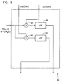
- Fig. 9 shows the expanded view of one possible embodiment of one of the analog filter elements of Fig. 8.
- Each analog filter unit has three inputs; a cosine wave cos(2 ⁇ f c ) , a sine wave sin(2 ⁇ f c ) , and the signal, either one of SIG s or CUR s from which the frequency component f c is to be extracted.
- the signal is multiplied by sin(2 ⁇ f c ) and cos(2 ⁇ f c ) in multipliers 84 and 86.
- the results are passed through low pass filters 88 and 90 to obtain the desired components of the signal.
- a remote object will have more than one set of sensors, preferably from 2 to 6 sets of sensors, that will provide sufficient parameters to determine the shape and/or configuration of a remote object, preferably relative to a reference frame.
- the catheter has additional sets of sensors located proximal to its distal tip, it would be possible to determine the shape and/or configuration of portions of the catheter.
- another invasive procedure such as a sigmoidoscopy or colonoscopy, it may be possible to determine the shape and/or configuration of some or all of the scope used.
- the controller is a simple off-the-shelf 486 IBM compatible computer.
- the A/D boards are commercially available and have the characteristic of being able to sample at least 8 channels with a sampling frequency of between 500 - 40,000 samples per second on each channel.
- An example of such an A/D Board is the National Instruments AT-MIO-16X that is available from National Instruments, Texas, USA.
- the D/A function is achieved using commercially available 8-21 bit resolution D/A boards. Examples of such a D/A are the National Instruments A/D,D/A Board AT-MIO-16X or National Instruments DSP model AT-DS2200.
- the radiation driver amplifiers are commercially available, with 2-16 ohms output impedance and an output power of 60-500 watts.
- An example of such amplifiers is the Inkel amplifier type NA-420, from Inkel of Seoul, Korea.
- the radiators are also commercially available and have the following characteristics: 1-6 cm radius, 0.5-3 cm thickness, and 100-500 turns made of copper wire of diameter 0.1 -0.95 mm.
- a specific example of such a coil could be coils having a 4 cm radius, 1 cm thickness with 151 turns of copper wire of 0.41 mm diameter.
- sensors may be suitable for some applications, such as Hall effect sensors, for example those available from Allegro Micro Systems, Inc., USA or magneto-resistor sensors, sensors, flux gate magnetic sensors, and/or other magnetic flux sensors.
- Hall effect sensors for example those available from Allegro Micro Systems, Inc., USA or magneto-resistor sensors, sensors, flux gate magnetic sensors, and/or other magnetic flux sensors.
- Controller 40 represents an assemblage of units to perform intended functions. For example, such units may receive information or signals, process information, function as a controller, display information, and/or generate information or signals. Typically controller 40 may comprise one or more microprocessors.
- active portion 16 of catheter 10 is a forward looking ultrasound send/receive transducer.
- a transducer can give a one-dimensional map of the acoustic properties of the material lying in front of it by radiating a focused beam of pulsed acoustic energy and then measuring the echoes of the beam reflected by changes in acoustic properties along the path of the beam.
- a focal beam of pulsed acoustic energy can be used to measure the echoes of the beam reflected by changes in acoustic properties along the path of the beam.
- such a steerable, one dimensional acoustic transducer can be used to map the heart walls or blood vessels, ultrasonically, from inside the heart.
- a transducer When coupled with a reference location sensor at a reference point on the heart and ECG gating of the acoustic pulses, such a transducer can generate the information required to form a three dimensional image of the heart or blood vessels or any other organ, at one or several different phases of the heart cycle.
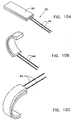
- Figs. 10A-10D The principle of two preferred embodiments of a steering mechanism are shown in Figs. 10A-10D and 11 respectively.
- Fig. 10A shows a steering mechanism 92 that fits into the distal end of a catheter and comprises two steering wires 94 attached to a steering head 96.
- Head 96 is formed of a relatively flexible material such as stainless steel and is slit along its axis, each side of the split being attached to one of wires 94.
- Such a head may be manufactured by attaching two wires (94) at their end and then flattening the wires to form a more easily bent structure.
- a relatively rigid housing containing locating sensor 14 and active portion 16 which, in the present preferred embodiment, is an ultrasonic send/receive transducer.
- active portion 16 which, in the present preferred embodiment, is an ultrasonic send/receive transducer.
- At least head 96 and wires 94 are encased in a catheter sheath 104 which is not shown in Figs. 10A-10C for clarity of presentation.
- This steering mechanism can also be used for other active portion types such as for electropysiologic mapping procedures and for improved steering of catheters or many types, with or without location sensing.
- Fig. 10B one of wires 94 has been shortened as compared with the other wire. Since the catheter sheath holds the wires together, the result of such shortening of one wire is bending of the head, which is facilitated by the axial slit. Locating sensor 14 and active portion 16 are rigidly attached so that measurement of position and orientation of the locating sensor will give the position and orientation of the active portion (ultrasound transducer). By varying the angle of bending and rotating the catheter, imaging over nearly 360° image can be achieved. Additionally or alternatively, as shown in Fig. 10C, the amount of rotation can be reduced by shortening the other wire and which causes bending in the other direction. Slight motion of the transducer can be corrected by a simple translation of the acquired one dimensional image associated with the particular position.
- Fig. 10D shows a mechanism 98 placed at the proximal end of the catheter for changing the relative lengths of wires 94.
- a handle 100 comprises a housing 102 to which catheter sheath 104 is attached.
- the proximal end of wires 94 are formed in a loop (for example by welding the ends of the wire) and wrapped around a spindle 106 which is preferably fixed and which forms a frictional contact with the wires.
- a lever 108 is rotatably attached near its center at a pin 110 to the housing and is attached at one end to wire 94 and at the other end to a slider 112 which is slidable parallel to the housing. When the slider is moved, one of the wires 94 at the distal end is lengthened with respect to the other.
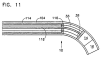
- Fig. 11 shows the distal end of a catheter having an alternative steering mechanism.
- a relative rigid sleeve 114 is placed within cathode sheath 104.
- Sleeve 114 can be axially displaced relative to the sheath from the proximal end of the catheter.
- sleeve 104 The distal end of sleeve 104 is formed with a disk 116 through which a relatively less rigid wire 118 passes.
- Wire 118 is formed with a permanent bend near its distal end at which end, position sensor 14 and active portion 16 are attached. Axial movement of sleeve 104 straightens wire 118 resulting in a change in orientation of both the position sensor and the active portion. If wire 118 is sited off axis, then rotating the wire will rotate the catheter.
- steering of acoustic beams may also be achieved by a moving mirror or by a phased array ultrasonic transducer, and that such a mirror or other arrangement may be present in the active portion.
- Such active scanning may supplement or replace the passive steering provided by the mechanisms of Figs. 10 and 11.
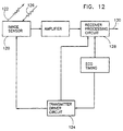
- Fig. 12 shows a simplified system block diagram of ultrasonic acquisition and image formation in accordance with a preferred embodiment of the invention.
- An image sensor 120 such as the ultrasound sensor described above, transmits an acoustic pulse 122 in response to a signal received from a transmitter driver circuit 124.
- An acoustic echo 126 (generally comprising several echoes) is received by the image sensor which produces an echo signal, which when amplified, is sent to a receiver processing circuit 128 which generates a one dimensional "image" at its output 130.
- Information identifying the heart phase of the image may also be present at output 130 which may comprise a plurality of output ports.
- the acquisition of the image is made in response to signals received from an ECG monitor 132. This allows for acquisition of images at a particular portion of the heart cycle so that the various one-dimensional images can be easily reconstructed into a three dimensional image.
- the most significant echo is used as the measure of the distance from the ultrasonic sensor to the chamber along the measurement direction of the sensor, then the collection of such distances (referenced to a reference point in the chamber) will allow the reconstruction of the surface morphology.
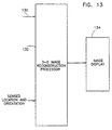
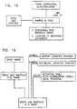
- Fig. 13 shows a simplified block diagram of a three dimensional image reconstruction system which utilizes a series of one dimensional images generated by the circuitry of Fig. 12 and continuous sensed location and orientation information generated by the position locator and its associated circuitry as described above. In general it is useful to acquire the sensed location and orientation to coincide with the acquisition of each one-dimensional image.
- One of the various methods described above for steering the distal tip of the catheter is used to acquire a plurality of one dimensional images with a plurality of orientations.
- An automatic mechanism may be used to continuously change the orientation of the imaging head in accordance with the principles of Figs. 10 and 11 and to rotate the catheter so that operator intervention is not required.
- An image reconstruction processor 132 orients and references the individual one dimensional images in accordance with the sensed location and orientation information and forms a 3-D image which can be presented on an image display 13 either in the form of a series of two dimensional slices or a full three dimensional reconstruction.
- the image displayed may be a cine image of the reconstruction.
- a two dimensional image is acquired by the ultrasound sensor which can be a phased array of acoustic crystals of a single crystal in conjunction with a mirror rotating about an axis that deflects the ultrasonic beam in a predetermined path.
- active portion 16 comprises a sensor for sensing electrical signals generated at selectable positions on the heart. As described below, such sensings of electrical signals can be used to map the electrical activity of the heart.
- the active portion may also include an electrode useful for pacing the heart and/or for ablating a portion of the heart. Such ablation is especially useful in the treatment of the most common lethal cardiac arrhythmia, ventricular tachycardia (VT), i.e., very rapid and ineffectual contractions of the heart muscle. VT is the cause of death of approximately 300,000 people annually. It is also useful in the treatment of other arrhythmias.
- VT ventricular tachycardia
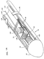
- FIG. 14 A catheter useful for electrical mapping of the heart/ablation is shown schematically in Fig. 14.
- Active portion 16 comprises a conducting tip, preferably of platinum, having a length of between 1-12 mm, preferably about 2 mm.
- the tip is connected via a tip electrode lead-in wire 138 to a switch at the proximal end of the cathode which switches the tip to a source of voltage for pacing or/ablating or to a detector for detecting electrical signals generated by the heart.
- a conducting ring electrode 136 is placed, proximal to locating sensor 14, on the outside of catheter sheath 104 and is connected to ground or to a recorder via a return lead 140.
- a 1-10 ma pulse is applied between tip 16 and ring electrode 136.
- When used for ablation RF energy at about 0.5 MHz and 10-100 V is applied for 10-200 sec.
- Locating sensor 14 is rigidly attached to the tip and the sensor and tip may be manipulated by an eccentric wire 142.
- the twisted wire leads are preferably shielded by a shield 144 to reduce pickup from the relatively high voltages carried by leads 138 and 140.
- an electrically insulating heat shield 146 is placed between the tip and the locating sensor.
- Fig. 15 is a schematic block diagram for acquiring a basic electrocardiogram map in accordance with a preferred embodiment of the invention.
- a transesophageal echocardiograph in the preferred embodiment, a multiplane image of the heart chambers is acquired prior to the mapping study. The image is acquired only during a fiducial point in time during the cardiac cycle. In the preferred embodiment, the image is acquired at end-diastole in response to an end diastole synch-signal. A three-dimensional image of the heart chambers is reconstructed indicating the endocardial morphology and the location of one or more reference catheters within the heart chamber.
- This image can be acquired by a 3-D transesophogal ultrasound image, by a CT scanner, by an MRI scanner or by other imaging techniques.
- the image can also be constructed by touching the catheter to the surface of the chamber (endocardium) in a number of places and measuring the positions. These points can then be used to describe a thee dimensionsional surface which represents the chamber surface.
- reference locatable catheters were placed at three positions in the heart to form a reference plane against which the position of the active catheter was referenced.
- these reference locatable catheters were placed, for example, in the right ventricular apex, the right atrial appendage, and the pulmonary artery at the level of the pulmonary valve, respectively.
- a reference catheter having a location sensor 14 as described hereinabove is used for reference purposes, only a single sensor is required to define the relative location and orientation of the mapping catheter. While any of these locations can be used, it is presently preferred to place the reference sensor in the distal coronary sinus.
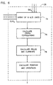
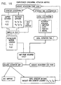
- Fig. 16 is a schematic block diagram for illustrating the computerized endocardial activation mapping algorithm (used during sinus rhythm mapping and during ventricular tachycardia mapping).
- a visible or audible indicator preferably indicates the beginning of a data point acquisition. Both electrical activity and location/orientation data are acquired for each point in the map.
- the acquisition of catheter location information is shown in left branch of the block diagram of Fig. 16.
- the mapper electrode is in steady and stable contact with the endocardium. Stable contact is determined by measuring the stability of the location reading, the stability of the sensed electrograms and the impedance of the contact.
- the position and orientation of the locating sensor in the mapping catheter are determined continuously in accordance with the method described above and are saved in response to an end diastole synch signal.
- the mapper catheter tip is localized relative to the reference catheter by finding the difference in each of the six dimensions of the location and orientation.
- the orientation of the mapper cathode is not required, however, it must be acquired to properly transform its location and orientation to an internal heart coordinate system.
- the activation time of the heart at the mapper cathode tip is determined as shown on the right side of Fig. 16.
- the local activation time is then defined with reference to the activation time measured by an ECG terminal on the skin of the patient.
- the process of data acquisition can be terminated by the user, or can be evaluated by an "evaluate activation map” algorithm described below, that examines the already acquired activation map for the density of information relative to the spatial gradient of activation times.
- This algorithm can indicate the next preferable site for activation time detection. The catheter is moved by the user to the new site, and the process of mapping continues.
- VT a data point is determined about every 4 to 6 heart beats. Thus, approximately 15 to 25, typically about 20, data points can be determined each minute.
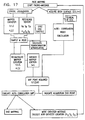
- Fig. 17 is a schematic block diagram for illustrating the computerized pace mapping algorithm.
- a visible or audible indicator indicates the beginning of a data point acquisition. Acquisition of position information is similar to that for Fig. 16 except that the average mapper location in the previous n heartbeats (n is the moving average window duration) is calculated.
- Fig. 17 shows the determination of the ACI (AutoCorelation Index) in a pace mapping mode.
- an ECG processor acquires ECG data while the patient's heart is paced by an external source at a rate similar to the patient's arrhythmia cycle length.
- the ECG data is also acquired from the body surface electrograms, and the signals are stored as a segment of ECG with a length of several cycles.
- the signal acquired is subjected to automatic comparison with the patient's own VT signal (see Fig. 18).
- the comparison between arrhythmia morphology and paced morphology is performed in two stages: First, the phase shift between the template VT signal and the paced ECG morphology is estimated using minimal error or maximal cross-correlation for two signals. Then, using this phase shift estimated from an index ECG channel, the similarity of the VT and the Raced ECG morphology is measured as the average of the cross-correlation or the square error of the two signals of all channels recorded.
- This two-stage calculation is repeated each time using a different ECG channel as the index channel for determining the phase shift.
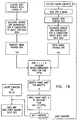
- Fig. 18 is a schematic block diagram illustrating an algorithm used to calculate the cross-correlation index while pace-mapping in accordance with a preferred embodiment of the invention.
- Body surface ECG data is acquired at two stages. First, during spontaneous or pacing induced VT, and second, during pacing the endocardium at different sites.
- the ECG data acquired during VT are signal averaged, and a template is constructed (T ch , for each channel recorded).
- T ch for each channel recorded.
- N the same number of beats
- the algorithm calculates the phase shift between P ch and Tch, which yields for the first channel the maximal cross-correlation.
- This time shift is used to shift the remaining channels and calculate for them the cross-correlation. All cross-correlations for all channels are summarized and stored. The algorithm then uses the next channel recorded to calculate the time shift that will cause maximal cross-correlation in this channel. Now this time shift is applied for all cross-correlations between P ch and T ch , and again all cross-correlations are summarized. This procedure is repeated for all channels, and the maximal cross-correlation achieved is used as the value of the cross-correlation of the T ch and the P ch at this site on the endocardium.
- FIG. 19 is a schematic block diagram for illustrating the output configuration of the present embodiment.
- a quasi-static picture of the heart chambers is presented as 3-D reconstruction of a basic image acquired prior to or during the study as previously described. Superimposed on the image is the location of the mapping/ablation catheter (corrected for the movement of the reference catheter) and the current and previous information acquired from the mapping study. This information may include, when appropriate, the activation times (presented using a color code at each acquisition site) or cross-correlation index (ACI) for each point in the pace map.
- the map can represent in the color coding the duration of the local electrograms, the presence of fragmented activity as well as various other variables calculated by the electrophysiologic processor.
- the catheter may be replaced by a needle whose tip is the locatable sensor port.
- electrographic maps of the heart are also possible. By use of variables determined from paced or non-paced acquisitions of electrographic data, the following additional maps can be generated:
- the sites where VT was terminated by a non-captured premature stimulus can be presented.
Abstract
Description
- The present invention relates to medical diagnosis, treatment and imaging systems. More particularly, the present invention relates to medical probes whose location can be detected and adjusted and which have an additional detection, imaging and/or treatment function, according to the preamble of claim 1.
- Probes, such as catheters, suitable for various medical procedures and internal imaging, are fairly common. Such probes include: balloon angioplasty catheters, catheters with laser-, electrical- or cryo-ablation characteristics, catheters having ultrasound imaging heads, probes used for nearly incisionless-surgery or diagnosis, and endoscopes. Where such probes are used for treatment, the probes must be carefully positioned in relation to the body structure. Even for imaging systems such as ultrasound systems, some positioning capability has been described.
- In cardiovascular examinations and in particular in those using invasive techniques, multiple catheters are inserted into the vascular system and then advanced towards the cardiac chambers. The procedure itself is generally performed under fluoroscope guidance which necessitates the use of a continuous source of x-ray as a transillumination source. The image generated using the fluoroscope is a 2D display of the anatomy with the location of the catheter superimposed. The anatomy can be viewed with a relatively low resolution since the cardiac chamber and the blood vessels are transparent to the x-ray radiation.
- More recently, several technologies have been developed to ease the process of cardiac catheterization, mainly by enabling the physician to follow the path of the tip of the catheter inside the blood vessel. Some of this technology is based on digital subtraction radiography technology that enables viewing the blood vessel after the injection of a radio contrast dye and superimposing on that image the path of the catheter. These technologies necessitate the use of radiopaque dyes which are a major cause of morbidity in high-risk patients during cardiac catheterization.
- U.S. Patent No. 5,042,486 to Pfeiller et al., describes a method in which the position of a catheter tip is located using electromagnetic fields. The catheter is introduced and the tip location is followed. The path of the tip is superimposed on the pre-registered image of the blood vessel or the organ, through which the catheter was advanced. However, this technology requires acquisition and processing of images prior to the procedure and involves a highly sophisticated and time-consuming procedure for the correct alignment of the image acquired previous to this procedure, and the orientation and location of the blood vessel or the organ during the catheterization procedure itself.
- U.S. Patent 4,821,731 to Martinelli et al., discloses a method for internal imaging of a living body using ultrasound. In this patent the position of an ultrasound imaging catheter is determined by computing the relative position of the catheter using the response of an ultrasound transducer to a reference signal and by computing the angular orientation of the catheter about its axis by determining the signal induced in a single coil by substantially perpendicular magnetic fields of different frequencies. The ultrasound transducer is also used to send and detect ultrasound signals in a direction perpendicular to the catheter axis. By rotating the catheter and moving it along its axis an ultrasound image may be generated. The catheter is also described as being capable of transmitting a laser beam to the end thereof to ablate tissue from lesions on the walls of arteries.
- A catheter which can be located in a patient using an ultrasound transmitter located in the catheter, is disclosed in U.S. Patent No. 4,697,595 and in the technical note "Ultrasonically Marked Catheter, a Method for Positive Echographic Catheter Position and Identification", Bryer et al., Medical and Biological Engineering and Computing, May, 1985, pages 268-271. Also, U.S. Patent No. 5,042,486 discloses a catheter which can be located in patients using non-ionizing fields and suitably imposing catheter location on a previously obtained radiological image of the blood vessel.
- PCT Patent Publication WO 94/0938, describes a system using a single-coil type sensor which is coaxial with the long axis of a catheter and which senses fields which are generated by three multicoil generators external to the body of a patient.
- Other methods and apparatus for the determination of the position of a catheter or endoscope are shown in U.S. Patents 5,253,647; 5,057,095; 4,095,598; 5,318,025; 5,271,400; 5,211,165; 5,265,610; 5,255,680; 5,251,635 and 5,265,611.
- U.S. Patent No. 3,644,825 describes a system which uses the relative motion of a sensor in the determination of its position. The relative motion supplies information to the sensing coils needed to identify position and orientation. However, such a solution is not applicable to identifying position and location of the object where there is no relative motion between the object and the reference frame.
- U.S. Patent No. 3,868,565, comprises a tracking system for continuously determining the relative position and orientation of a remote object. This tracking system includes orthogonally positioned loops for both a plurality of sensors and a plurality of radiating antennas. With the proper excitation currents to those loops, the radiating antennas generate an electromagnetic field that is radiated from those antennas to the sensor. The tracking system operates as a closed loop system where a controlling means measures the field that is received at the sensor at the remote object and feeds the information back to radiating antennas to provide a nutating field radiating as a pointing vector towards the remote object. Accordingly, the pointing vector gives the direction to the sensing antenna from the radiating antenna.
- Similarly, Kuipers describes in his U.S. Patent No. 4,017,858, an electromagnetic field which rotates about a pointing vector and is used both to track or locate the remote object in addition to determining the relative orientation of the object. This system, wherein the radiating coils are charged with the properly designed wave forms, generates a magnetic field which, in a closed loop manner, can be fed into processing means to generate the information needed to determine an orientation of a remote object.
- U.S. Patent No. 4,054,881, describes a non-tracking system for determining the position and location of a remote object with respect to a reference frame. This is accomplished by applying electrical signals to each of three mutually-orthogonal, radiating antennas, the electrical signals being multiplexed with respect to each other and containing information characterizing the polarity and magnetic moment of the radiated electromagnetic fields. The radiated fields are detected and measured by the three mutually orthogonal receiving antennas having a known relationship to the remote object, which produce nine parameters. These nine parameters, in combination with one known position or orientation parameter, are sufficient to determine the position and orientation parameters of the receiving antennas with respect to the position and orientation of the radiating antennas.
- U.S. Patent No. 4,849,692, describes a quantitative method for measuring the relative position and orientation of two bodies in the presence of metals. Measuring the position and orientation of receiving antennas with respect to the transmitting antennas is achieved using direct current electromagnetic field signals. Electromagnetic radiation is designed to be transmitted in a sequence by each of the mutually orthogonal radiating antennas. A receiving antenna measures the values of transmitted direct current magnetic fields, one dimension at a time, and those of the earth's magnetic field as well. This method requires repetitive acquisition and computations to determine position and location of remote objects.
- Other methods which are known in the art for determining multi-dimensional positioning and orientation for aircraft and for helmets are described in U.S. Patent 4,849,692, European patent publication 0 576 187 A1, GB patent publication 2 197 078 A and U.S. Patent 4,314,251.
- The above described prior art which is for use in nonmedical applications, utilizes sensors and other structures which are not suitable for use in catheters. Those references which are described as being useful for medical probes generally give less than six dimensional information (three position coordinates and three angular coordinates).
- In document WO 95/02995, which constitutes prior according to Article 54(3) EPC, a system is disclosed which incorporates a catheter which includes a position measuring device which can determine the position of the catheter in three dimensions, but not its orientation. In these applications, this catheter is used to map the electrical activity at the inner walls of the heart and to ablate portions of the heart muscle in response to such mappings. The position of the catheter used for the mapping/ablation function is determined with reference to three position detecting devices which are positioned against the inner wall of the heart at three different stable locations to form a reference plane.
- WO-A-90/13259 shows an ultrasound transducer fixed in its axial rotation capability. To generate three-dimensional ultrasound representations knowledge of the transducer position around the axis is not essential. The position is calculated using two sensors and two field induction loops.
- WO-A-92/03090 uses an axial symmetrical catheter wherein the degree of freedom of rotation around its axis is not relevant. The coils shown are all axially directed and cannot be used to determine the orientation angle about the axis of the catheter.
- The present invention is defined in independent claims 1 and 30. It concerns a catheter locating means and method that offers quantitative, high resolution locating information that, when assimilated with sensed local information results in a high resolution detailed map of the information. This map may optionally be superimposed on an image or other representation of the organ architecture.
- The locating means preferably generates continuous location and orientation information concerning a remote object, in particular a catheter, relative to a reference frame, in a non-iterative manner.
- One aspect of the present invention relates to the provision of a new six-dimensional positioning apparatus suitable for use with a catheter.
- In a preferred embodiment of this system, a plurality of non-concentric coils are placed in a catheter adjacent a locatable site, for example, its distal end. The coils preferably have orthogonal axis. The relative positioning of the coils differs from that described in the prior art in that the coils are separated in space and are not concentric. These coils generate signals in response to externally applied magnetic fields which allows for the computation of six position and orientation dimensions.
- A second aspect of the present invention is directed toward a new method for computing multi-dimensional position and orientation of a coil system from signals produced by the coils in response to a system of externally applied electromagnetic fields.
- A third aspect of the present invention allows for the mapping of the interior of the heart in a manner similar to that described in the above-referenced patent applications assigned to the assignee of the present application, with the simplification that only a single six-dimensional location/orientation detection sensor is used for reference.
- A fourth aspect of the present invention involves an ultrasonic or other imaging probe having a six-dimensional positioning capability in response to external electromagnetic fields. Use of such a probe obviates the use of ionizing radiation or sonic sensing for position determination and gives ultrasonic or other imaging information whose direction and orientation is completely known.
- A fifth aspect of the invention involves methods and apparatus for adding a controlled change in orientation to a catheter, thereby to allow for maneuvering of the cathode and its easy placement.
- A sixth aspect of the invention utilizes the controlled change in orientation to allow for two or three-dimensional imaging using a non-scanning probe, such as an ultrasound probe or for three-dimensional scanning using a two-dimensional scanning probe.
- Preferably one or both of the plurality of field generators or sensors comprises three distinguishable, non-overlapping, generators or sensors.
- In a preferred embodiment of the invention, each sensor comprises a coil. Preferably, said plurality of coils have axes which intersect within a coil. When said plurality of coils comprises three coils, said coils preferably have axes which do not all intersect in a point.
- Preferably, the signal processor cross-correlates the signals corresponding to the drive and sensor signals.
- Preferably, the fields generated by each of the generators have a different frequency, a different phase, or both a different frequency and a different phase.
- In a preferred embodiment of the invention the field generated by each field generator has a different frequency, preferably frequencies which are each integer multiples of a given frequency. Preferably, the duration of the cross-correlation of the inputs is the minimal common product of the integer multipliers divided by the given frequency.
- Preferably, the results of the cross-correlation are used to calculate the contribution of each field generator to the signal generated by each said sensor.
- In a preferred embodiment of the invention the locating system includes a display system for displaying the position of the point on the invasive medical instrument.
- Preferably, the locating system further comprises a reference instrument which includes a plurality of additional non-overlapping sensors situated in a reference instrument which sensors generate sensor sighals in response to said fields, wherein said display system displays the position of the portion on the invasive medical instrument relative to the position of a point on the reference instrument. Preferably the reference instrument is an invasive medical instrument. Preferably, the sensors are situated proximate the distal end of the reference invasive medical instrument.
- In a preferred embodiment of the invention the locating system includes an additional sensor on a portion of the invasive medical instrument which senses a local condition.
- Preferably, the additional sensor senses local electrical signals, for example electrical signals from the endocardium of the patient's heart, and transfers them to terminals external to the patient's body.
- In a preferred embodiment of the invention the signal processor processes the position and orientation coordinate signals and the local electrical signals acquired at a plurality of points on the endocardium to generate a map that represents the propagation of electrical signals through tissue in the patient's body.
- In a preferred embodiment of the invention the additional sensor supplies electrical energy to the endocardium for ablating a portion of the endocardium.
- Preferably the locating system includes an electrode adapted for supplying electrical energy to the endocardium for ablating a portion of the endocardium.
- In a preferred embodiment of the invention the additional sensor is an ultrasonic transmitter/receiver.
- Preferably, the ultrasonic transmitter/receiver provides a less than three dimensional representation of the acoustic properties of tissue beyond the distal end.
- In a preferred embodiment of the invention, the distal end is deflectable. Preferably, the system includes image reconstruction circuitry which receives a plurality of said less than three dimensional representations acquired at different orientations of the distal end and produces a three dimensional map of the acoustic properties of tissue at least partially surrounding the distal end.
- The invasive medical instrument may be, for example, a catheter or endoscope, comprising a plurality of magnetic field sensors, preferably coils, proximate the distal end thereof.
- Preferably the plurality of coils have axes which intersect within a coil. Where the plurality is three, the said coils have axes which do not all intersect in a point.
- In a preferred embodiment of the invention, the instrument comprises an ultrasound transducer at said distal end. Preferably, the ultrasound transducer provides a representation, preferably a one or two dimensional representation, of the acoustic properties of tissue beyond and along the axis of the catheter.
- In a preferred embodiment of the invention, the instrument further comprises an electrical probe at said distal end. The probe is preferably adapted to sense electrical signals generated by tissue which is in contact and conduct said signals to the proximal end of the catheter and/or to supply an ablative electrical signal to tissue contacting said terminal. In a preferred embodiment of the invention, the instrument includes a sensor for measuring local chemistry at the distal end.
- Preferably, the instrument includes means for changing the orientation of the distal end.
-
- Fig. 1 is a pictorial representation of the application of a system for six-dimensional position and bearing determination, in accordance with a preferred embodiment of the invention to a catheter located in a human body;
- Fig. 2 is a schematic, cut-away illustration of a generalized catheter having a six-dimensional location capability in accordance with a preferred embodiment of the present invention;
- Fig. 3 is a more graphic illustration of a portion of the probe showing a preferred embodiment of a sensor for six-dimensional location;
- Fig. 4 is a block diagram of circuitry used to determine the six-dimensional coordinates of a catheter, in accordance with a preferred embodiment of the invention;
- Fig. 5 shows in expanded detail the basic flow chart representing a control sequence and its application to the block diagram of Fig. 4, in accordance with a preferred embodiment of the invention;
- Fig. 6 is a block diagram representing digital signal processing in the signal processor in accordance with a preferred embodiment of the invention;
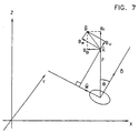
- Fig. 7 is a three-dimensional graphic representation of the vectors forming the magnetic field at a point;
- Fig. 8 is a block diagram representing analog signal processing in the signal processor, in accordance with a preferred embodiment of the invention;
- Fig. 9 is a simplified schematic of an analog filter element shown in Fig. 8, in accordance with a preferred embodiment of the invention;
- Figs. 10A-10D illustrate a principle of orienting the tip of a catheter in accordance with a preferred embodiment of the invention;
- Fig. 11 illustrates a principle of orienting the tip of a catheter in accordance with a preferred embodiment of the invention;
- Fig. 12 is a block diagram of ultrasonic acquisition and signal processing circuitry in accordance with a preferred embodiment of the invention;
- Fig. 13 is a block diagram of image reconstruction circuitry in accordance with a preferred embodiment of the invention;
- Fig. 14 is a partially schematic, partially cut-away illustration of a probe for electrical sensing, pacing and ablation in accordance with a preferred embodiment of the invention;
- Fig. 15 is a schematic block diagram for acquiring a basic electrogram map in accordance with a preferred embodiment of the present invention;
- Fig. 16 is a schematic block diagram representing a computerized endocardial mapping algorithm, in accordance with a preferred embodiment of the invention;
- Fig. 17 is a schematic block diagram representing a computerized pace mapping algorithm, in accordance with a preferred embodiment of the invention;
- Fig. 18 is a schematic block diagram of an algorithm used to calculate the cross-correlation index while pace-mapping, in accordance with a preferred embodiment of the invention; and
- Fig. 19 is a schematic block diagram representing an output configuration of an imaging system in accordance with a preferred embodiment of the invention.
-
- Figure 1 shows a pictorial representation of a basic preferred application of the invention to the human body. In this application, a catheter 10 is inserted into an artery 11 of a patient using standard techniques. Catheter 10 comprises a body 12, a locating sensor 14 and an active portion 16 at the distal end 15 of the catheter. The active portion 16, in accordance with various preferred embodiments of the invention, may include an electrical sensor, an ultrasound head, a fiber optic viewing head, an electrical stimulator, an electrical or laser ablator, an ionic sensor, an oxygen or carbon dioxide sensor, an accelerometer, a blood pressure or temperature sensor or a cryogenic probe. In general the catheter will include leads, light guides, wave guides, etc. for energizing the active portion in response to commands of an operator.
- The position and orientation of the distal end of the catheter is ascertained by determining the position of the locating sensor. In a preferred embodiment of the invention, the locating sensor 14 comprises two or three antennas, for example coils which are irradiated by two or three radiators 18, 20 and 22, which are outside the body surface 23 of the patient.
- It should be understood that placement of the radiators, as well as their size and shape, will vary according to the application of the invention. Preferably the radiators useful in a medical application comprise wound annular coils from about 2 to 20 cm in diameter (O.D.) and from about 0.5 to 2 cm thick, in a coplanar, triangular arrangement where the centers of the coils are from about 2 to 30 cm apart. Bar-shaped radiators or even triangular or square-shaped coils could also be useful for such medical applications. Moreover, in instances where a prone patient will be the subject of a procedure involving the instant technology, the radiators are preferably positioned in or below the surface upon which the patient is resting, substantially directly below the portion of the patient's body where a procedure is being performed. In other applications, the radiators may be fairly close to the skin of the patient.
- The three radiators are driven by a radiator driver 24, preferably in a manner described below, and the signals received by the receiving antennas are amplified and processed, together with a representation of the signals used to drive radiators 18, 20 and 22, preferably in the manner described below, in a signal processor 26 to provide a display or other indication of the position and orientation of the distal end 15 on a monitor 27.
- Radiators 18, 20 and 22 may be arranged in any convenient position and orientation, so long as they are fixed in respect to some reference frame, and so long as the radiators are non-overlapping, that is, there are no two radiators with the exact, identical location and orientation. When driven by radiator driver 24, the radiators generate a multiplicity of distinguishable AC magnetic fields that form the magnetic field sensed by receiving antennas in the locating sensor.
- The magnetic fields are distinguishable with regard to the frequency, phase, or both frequency and phase of the signals in the respective magnetic fields. Time multiplexing is also possible.
- In practice the active end of the catheter may be used to gather information, such as ultrasound echo information, electrical activity information etc., and optionally to perform certain procedures on the arteries (or veins) or within an organ chamber 28 to which the artery (or vein) leads. Particular examples of organ chambers are the chambers of the heart, brain or gastrointestinal tract. It is a particular object of some aspects of the present invention to more accurately map the electrical activity of the heart and to more accurately image the walls of the heart, as will be described in more detail below.
- Fig. 2 shows a schematic illustration of a preferred embodiment of the distal end of catheter 10. A graphic illustration of locating sensor 14 is shown in Fig. 3. Sensor 14 preferably includes two or more and more preferably three sensor coils 30, 32 and 34 wound on air cores. In a preferred embodiment of the invention the coils have mutually orthogonal axes, one of which is conveniently aligned with the long axis of the catheter. Unlike prior art location sensors (used for other applications) which contain three coils that are concentrically located, or at least whose axes intercept, the coils of the preferred embodiment of the invention are closely spaced along the axis of the catheter to reduce the diameter of the locating sensor and thus make the sensor suitable for incorporation into a catheter.
- For most aspects of the present invention, quantitative measurement of the position and orientation of the catheter distal end relative to a reference frame is necessary. This requires at least two non-overlapping radiators that generate at least two distinguishable AC magnetic fields, the radiators' respective positions and orientations relative to the reference frame being known; a radiator driver which preferably continuously supplies the radiators with AC signals to generate the AC magnetic fields; and a location sensor, consisting of at least two non-parallel sensors to measure the magnetic field flux resulting from the at least two distinguishable magnetic fields. The number of radiators times the number of sensors is equal to or greater than the number of degrees of freedom of the desired quantitative measurement of the position and orientation of the sensors relative to the reference frame.
- Since, according to the invention the six position and orientation coordinates of the distal tip of the catheter are determined, at least two coils are required in location sensor 14. Preferably three coils are used to improve the accuracy and reliability of the position measurement.
- Leads 36 are used to carry signals detected by the sensor coils to signal processor, via the proximal end of the catheter, for processing to generate the required position information. Preferably, leads 36 are twisted pairs to reduce pick-up and may be further electrically shielded.
- In a preferred embodiment of the invention, coils 30, 32 and 34 have an inner diameter of 0.5 mm and have 800 turns of 16 micrometer diameter to give an overall coil diameter of 1-1.2 mm. The effective capture area of the coil is preferably about 400 mm2. It will be understood that these dimensions may vary over a considerable range and are only representative of a preferred range of dimensions. In particular, the size of the coils could be as small as 0.3 mm (with some loss of sensitivity) and as large as 2 or more mm. The wire size can range from 10-31 micrometers and the number of turns between 300 and 2600, depending on the maximum allowable size and the wire diameter. The effective capture area should be made as large as feasible, consistent with the overall size requirements. While the preferred sensor coil shape is cylindrical, other shapes can also be used. For example a barrel shaped coil can have more turns than a cylindrical shaped coil for the same diameter of catheter. Also, square or other shaped coils may be useful depending on the geometry of the catheter.
- Leads 38 are used to power active portion 16 and/or to receive signals therefrom. The nature of leads 38, which may vary and may, for example, include an optical waveguide or other transmission media as appropriate to their task.
- For example, an electrode located on the distal tip of the catheter records local cardiac electrical activity, for example, on the endocardium. These local electrograms (ECG's) are transferred via leads 38 to the proximal end of the catheter and fed into an ECG amplifier. The amplified ECG signals are transferred to the control system that presents to the physician the local electrogram morphology acquired from the site whose location was determined at the same time.
- Figure 4 is a block diagram of preferred circuitry used in computing the position of locating sensor 14. In this exemplary embodiment, three radiators 18, 20 and 22 and three sensor coils 30, 32 and 34 are used. Radiator driver 24 provides distinguishable, simultaneous AC current signals to each radiator. Control circuitry 40 utilizes D/A convertors 42, 44 and 46 to generate three sine waves of three different frequencies, f1, f2 and f3, which are output separately to signal amplifiers 48, 50 and 52.
- In order to achieve a fast response locating system the use of slow responding filters has been eliminated by using cross-correlation of the radiated and the received signals. This cross-correlation is performed over a window in time which contains an integer number of the cycle lengths of the three radiated signals. Use of an integer number of cycles generally results in a decrease in processing errors and a more accurate determination of the relative amplitude and phase of the signals received by the sensor coils. If non-integral cycle lengths are used an error in the cross-correlation generally results, unless a very long correlation window is used.
- If a short correlation window is used, (the shortest is the minimal common product of the cycle times), the ratio between frequencies should be a rational number. The frequency of a radiator c, fc, where c = 1, 2 or 3 should satisfy the equation:
- The radiating driver amplifier output signals are delivered to the radiators through current sensitive circuitry 54, 56 and 58, such as a resistor, loop or more sophisticated circuitry as is known in the art. The current-sensitive circuitry produces an output which represents the amplitude and phase of the driving signal for the radiators and which is passed to signal processor 26. With this arrangement, the three radiators will generate a magnetic field composed of three differently oriented field components each having a different known frequency. Each of these field components will be sensed by each of sensor coils 30, 32 and 34 which will each produce a signal composed of three frequency components having different amplitudes and phases depending on the relative distance and orientation of the particular sensor coil and particular radiator which radiates a particular frequency.
- The outputs signals of sensors 30, 32 and 34 are amplified in amplifiers 60, 62 and 64 respectively and passed on to signal processor 26.
- Fig. 5 shows in expanded detail the basic flow chart representing a control sequence and its application to the circuitry of Fig. 4. During the initialization phase, indicated by block 66, the frequencies of the three sine waves, the physical position and orientation of radiators 18, 20 and 22 in respect to a reference frame, the properties of the radiators and sensors and the coordinates of a single point in the mapping field are defined. Sine waves having respective frequencies f1, f2 and f3 are synthesized as indicated by block 68, for example in control 40. These generated frequencies are transmitted, preferably continuously, by radiators 18, 20 and 22 as indicated by block 70 and as described above with reference to Fig. 4. The control sequence enters a timing loop 72 that periodically sends signals to activate the signal processor to cross-correlate the coil sensor signals with the radiated signals and to calculate the orientation and position of locating sensor 14 relative to the reference frame.
- Both analog and digital embodiments of signal processing are possible in accordance with preferred embodiments of the invention. These different approaches can be modified in a variety of ways by those skilled in the art, and can be combined in different modes in order to practice them simultaneously. Some applications of the present invention would benefit from the digital approach, while the analog approach may be the preferable solution in other cases.
- The digital embodiment is described in conjunction with Fig. 6, which is a functional block diagram of signal processor 26. The inputs to the processing block are the signals from amplifiers 60, 62 and 64 (the sensor coil signals) denoted by SIG and inputs from current sensing circuits 52, 56 and 58 denoted as CUR. In this embodiment the six input signals are converted from analog to digital signals by an array of A/D converters 74. The sampled digital signals are passed to the "calculate cross correlation" block 76, which may consist of dedicated circuitry or which may be performed by a dedicated or shared microprocessor. Using the six data streams (three AC currents flowing through the radiators and three sensor readings) the cross correlation elements can be calculated using the following method:
- Given that
- SIGs is the amplified output of sensor s, where s = 1, 2 or 3;
- CURc is the current flowing through radiator c, where c= 1, 2 or 3;
- fb is an arbitrary base frequency;
- f0 is the sampling frequency which is an integral multiple of fb; and
- and N is the correlation length in number of samples,
-
- A preferred ratio of f1, f2 and F3 is 1, 2, 3 and preferred frequencies are 1, 2 and 3 kHz. The useful frequency range is believed to lie between 50 Hz and 50 kHz.
- The calculation of the fields and currents, designated by block 78, can also be performed using either dedicated circuitry or a dedicated or shared microprocessor. The amplitude of the current through each radiator Ac can be calculated using:
- The phase between the current in radiator c and the field sensed by sensor s, Ψs,c, is
- The magnetic field for every possible location and orientation of the sensor in the mappable space can be obtained by using:
- 1) The field equations of the radiators used in a specific embodiment,
- 2) The exact position and orientation of the radiators, and
- 3) The current flowing through the radiators Ac.
-
- Preferably the contributions of each field generator are used to solve a set of field equations, which are dependent upon the field form. Solving these equation sets produces the location and orientation of the remote sensors, most preferably simultaneously.
- More particularly, the field equations are derived specifically for each embodiment and are dependent on the geometry and characteristics of the radiators. In the preferred embodiment of the invention where the radiators are coils, the field equations can be described as follows:
- For a coil with N turns a radius R and a current I, the radial field component at a distance r is
- P 1 / n (X) is a generalized Legendre Polynomial of degree n, and calculated by:

- These field equations are correct for r>R for a radiator located in location
P . The field induced at locationK is, as shown in Fig. 7, given by:P and W ∧ is a unit vector in the tangential direction of the radiator located atP . Using this general field equation one can calculate the field at pointK generated by each of the radiators. - The remote sensor orientation, denoted by V ∧ determines the field sensed by this sensor at this location (
K ). - Therefore the field sensed by a remote sensor is
K and V ∧ are the unknown variables, and O ∧,P and I are the known variables for any given coil. - In the example embodiment there are three radiators; therefore there will be three known values of
P and three known values of O ∧. The three sensors have a fixed and known location and orientation in the remote object reference frame. For each position and orientation of the remote object, one can compute the location and orientation of each sensor in the radiator reference frame and therefore compute the field sensed, Bv, for each radiator and each sensor. In the case of the present location system, each field sensed by each sensor from every radiator is measured and the field equations are solved to obtain the location and orientation of the remote object (x, y, z, ε,ξ,and ζ). - The results of this approach for the three radiator, three sensor system used here as an example, are nine non-linear algebraic equations with six variables (namely, x, y, z of the sensing means position and ε,ξ, and ζ for the location sensor orientation) in the form of:
- In this embodiment of the invention, the nine sensor readings (Bs,c) are the measured quantity, and by solving this overdetermined system of equations (using a variety of known numerical methods such as the Newton-Raphson method for non-linear systems of equations or Multidimensional Secant Methods, specifically Broyden's method), the location and orientation of location sensor 14 is determined. A description of several possible numerical methods for solving such a set of equations is found in William H. Press et al, "Numerical Recipes in C. The Art of Scientific Computing", second edition, Cambridge University Press, 1992. The location sensor position and orientation are displayed on monitor 27.
- An ECG monitor may be used to synchronize the acquisition of the signals from the sensor coils so as to remove cardiac motion artifacts from the position information. Furthermore, a reference sensor may be attached to a portion of an organ being tested or treated, such as the heart, which will be used to correct for breathing motion or patient movement. In this way, the acquired sensor positions may be referenced to the organ structure and not to an absolute outside reference frame, which is less significant.
- In an analog based embodiment of signal processor 26, some of the parameters are calculated using analog circuitry. Fig. 8 is a schematic of one analog based embodiment of signal processor 26. In this embodiment, three sine and three cosine wave signals of frequency f1, f2, and f3, are used in addition to the SIG and CUR signals used in the embodiment of Fig. 6. The SIG and CUR signals are filtered by 12 phase sensitive filters (correlators) 80, such as are shown in Fig. 9 to produce signals indicative of the sine and cosine components of the SIG and CUR signals.
- These analog signals are then passed to a set of A/D converters 82. The fields and currents and positions are calculated in the same manner as described above with respect to Fig. 6.
- Fig. 9 shows the expanded view of one possible embodiment of one of the analog filter elements of Fig. 8. Each analog filter unit has three inputs; a cosine wave
- The description above primarily concerns acquiring information by a set of two or more sensors that is used to determine the position and orientation of a remote object or a point on a remote object such as a medical device or instrument. It is also within the scope of the invention that a remote object will have more than one set of sensors, preferably from 2 to 6 sets of sensors, that will provide sufficient parameters to determine the shape and/or configuration of a remote object, preferably relative to a reference frame. For example, if the catheter has additional sets of sensors located proximal to its distal tip, it would be possible to determine the shape and/or configuration of portions of the catheter. Similarly, for another invasive procedure such as a sigmoidoscopy or colonoscopy, it may be possible to determine the shape and/or configuration of some or all of the scope used.
- The equipment necessary to practice the invention is mostly conventional. In one embodiment of the invention, the controller is a simple off-the-shelf 486 IBM compatible computer. The A/D boards are commercially available and have the characteristic of being able to sample at least 8 channels with a sampling frequency of between 500 - 40,000 samples per second on each channel. An example of such an A/D Board is the National Instruments AT-MIO-16X that is available from National Instruments, Texas, USA. The D/A function is achieved using commercially available 8-21 bit resolution D/A boards. Examples of such a D/A are the National Instruments A/D,D/A Board AT-MIO-16X or National Instruments DSP model AT-DS2200. The radiation driver amplifiers are commercially available, with 2-16 ohms output impedance and an output power of 60-500 watts. An example of such amplifiers is the Inkel amplifier type NA-420, from Inkel of Seoul, Korea. The radiators are also commercially available and have the following characteristics: 1-6 cm radius, 0.5-3 cm thickness, and 100-500 turns made of copper wire of diameter 0.1 -0.95 mm. A specific example of such a coil could be coils having a 4 cm radius, 1 cm thickness with 151 turns of copper wire of 0.41 mm diameter.
- While the sensor described above is preferred, other sensors may be suitable for some applications, such as Hall effect sensors, for example those available from Allegro Micro Systems, Inc., USA or magneto-resistor sensors, sensors, flux gate magnetic sensors, and/or other magnetic flux sensors.
- Controller 40 represents an assemblage of units to perform intended functions. For example, such units may receive information or signals, process information, function as a controller, display information, and/or generate information or signals. Typically controller 40 may comprise one or more microprocessors.
- In accordance with a preferred embodiment of the invention, active portion 16 of catheter 10 is a forward looking ultrasound send/receive transducer. Such a transducer can give a one-dimensional map of the acoustic properties of the material lying in front of it by radiating a focused beam of pulsed acoustic energy and then measuring the echoes of the beam reflected by changes in acoustic properties along the path of the beam. In order to provide a three dimensional image it is necessary to change the direction of the beam, preferably without changing its position by a great amount.
- In particular, such a steerable, one dimensional acoustic transducer can be used to map the heart walls or blood vessels, ultrasonically, from inside the heart. When coupled with a reference location sensor at a reference point on the heart and ECG gating of the acoustic pulses, such a transducer can generate the information required to form a three dimensional image of the heart or blood vessels or any other organ, at one or several different phases of the heart cycle.
- The principle of two preferred embodiments of a steering mechanism are shown in Figs. 10A-10D and 11 respectively. Fig. 10A shows a steering mechanism 92 that fits into the distal end of a catheter and comprises two steering wires 94 attached to a steering head 96. Head 96 is formed of a relatively flexible material such as stainless steel and is slit along its axis, each side of the split being attached to one of wires 94. Such a head may be manufactured by attaching two wires (94) at their end and then flattening the wires to form a more easily bent structure.
- Attached to the distal end of the steering head is a relatively rigid housing containing locating sensor 14 and active portion 16 which, in the present preferred embodiment, is an ultrasonic send/receive transducer. At least head 96 and wires 94 are encased in a catheter sheath 104 which is not shown in Figs. 10A-10C for clarity of presentation. This steering mechanism can also be used for other active portion types such as for electropysiologic mapping procedures and for improved steering of catheters or many types, with or without location sensing.
- In Fig. 10B one of wires 94 has been shortened as compared with the other wire. Since the catheter sheath holds the wires together, the result of such shortening of one wire is bending of the head, which is facilitated by the axial slit. Locating sensor 14 and active portion 16 are rigidly attached so that measurement of position and orientation of the locating sensor will give the position and orientation of the active portion (ultrasound transducer). By varying the angle of bending and rotating the catheter, imaging over nearly 360° image can be achieved. Additionally or alternatively, as shown in Fig. 10C, the amount of rotation can be reduced by shortening the other wire and which causes bending in the other direction. Slight motion of the transducer can be corrected by a simple translation of the acquired one dimensional image associated with the particular position.
- Fig. 10D shows a mechanism 98 placed at the proximal end of the catheter for changing the relative lengths of wires 94. A handle 100 comprises a housing 102 to which catheter sheath 104 is attached. The proximal end of wires 94 are formed in a loop (for example by welding the ends of the wire) and wrapped around a spindle 106 which is preferably fixed and which forms a frictional contact with the wires.
- A lever 108 is rotatably attached near its center at a pin 110 to the housing and is attached at one end to wire 94 and at the other end to a slider 112 which is slidable parallel to the housing. When the slider is moved, one of the wires 94 at the distal end is lengthened with respect to the other.
- Fig. 11 shows the distal end of a catheter having an alternative steering mechanism. A relative rigid sleeve 114 is placed within cathode sheath 104. Sleeve 114 can be axially displaced relative to the sheath from the proximal end of the catheter.
- The distal end of sleeve 104 is formed with a disk 116 through which a relatively less rigid wire 118 passes. Wire 118 is formed with a permanent bend near its distal end at which end, position sensor 14 and active portion 16 are attached. Axial movement of sleeve 104 straightens wire 118 resulting in a change in orientation of both the position sensor and the active portion. If wire 118 is sited off axis, then rotating the wire will rotate the catheter.
- It should be understood that steering of acoustic beams may also be achieved by a moving mirror or by a phased array ultrasonic transducer, and that such a mirror or other arrangement may be present in the active portion. Such active scanning may supplement or replace the passive steering provided by the mechanisms of Figs. 10 and 11.
- Fig. 12 shows a simplified system block diagram of ultrasonic acquisition and image formation in accordance with a preferred embodiment of the invention. An image sensor 120, such as the ultrasound sensor described above, transmits an acoustic pulse 122 in response to a signal received from a transmitter driver circuit 124. An acoustic echo 126 (generally comprising several echoes) is received by the image sensor which produces an echo signal, which when amplified, is sent to a receiver processing circuit 128 which generates a one dimensional "image" at its output 130. Information identifying the heart phase of the image may also be present at output 130 which may comprise a plurality of output ports. In one embodiment of the invention, especially useful for heart imaging, the acquisition of the image is made in response to signals received from an ECG monitor 132. This allows for acquisition of images at a particular portion of the heart cycle so that the various one-dimensional images can be easily reconstructed into a three dimensional image.
- In particular, if the most significant echo is used as the measure of the distance from the ultrasonic sensor to the chamber along the measurement direction of the sensor, then the collection of such distances (referenced to a reference point in the chamber) will allow the reconstruction of the surface morphology.
- Fig. 13 shows a simplified block diagram of a three dimensional image reconstruction system which utilizes a series of one dimensional images generated by the circuitry of Fig. 12 and continuous sensed location and orientation information generated by the position locator and its associated circuitry as described above. In general it is useful to acquire the sensed location and orientation to coincide with the acquisition of each one-dimensional image. One of the various methods described above for steering the distal tip of the catheter is used to acquire a plurality of one dimensional images with a plurality of orientations. An automatic mechanism may be used to continuously change the orientation of the imaging head in accordance with the principles of Figs. 10 and 11 and to rotate the catheter so that operator intervention is not required.
- An image reconstruction processor 132 orients and references the individual one dimensional images in accordance with the sensed location and orientation information and forms a 3-D image which can be presented on an image display 13 either in the form of a series of two dimensional slices or a full three dimensional reconstruction. When images at different points in the heart cycle are acquired, the image displayed may be a cine image of the reconstruction.
- In a preferred embodiment of the invention a two dimensional image is acquired by the ultrasound sensor which can be a phased array of acoustic crystals of a single crystal in conjunction with a mirror rotating about an axis that deflects the ultrasonic beam in a predetermined path.
- In a preferred embodiment of the invention active portion 16 comprises a sensor for sensing electrical signals generated at selectable positions on the heart. As described below, such sensings of electrical signals can be used to map the electrical activity of the heart. The active portion may also include an electrode useful for pacing the heart and/or for ablating a portion of the heart. Such ablation is especially useful in the treatment of the most common lethal cardiac arrhythmia, ventricular tachycardia (VT), i.e., very rapid and ineffectual contractions of the heart muscle. VT is the cause of death of approximately 300,000 people annually. It is also useful in the treatment of other arrhythmias.
- A catheter useful for electrical mapping of the heart/ablation is shown schematically in Fig. 14.
- Active portion 16 comprises a conducting tip, preferably of platinum, having a length of between 1-12 mm, preferably about 2 mm. The tip is connected via a tip electrode lead-in wire 138 to a switch at the proximal end of the cathode which switches the tip to a source of voltage for pacing or/ablating or to a detector for detecting electrical signals generated by the heart. A conducting ring electrode 136 is placed, proximal to locating sensor 14, on the outside of catheter sheath 104 and is connected to ground or to a recorder via a return lead 140. When used for pacing, as described below, a 1-10 ma pulse is applied between tip 16 and ring electrode 136. When used for ablation RF energy at about 0.5 MHz and 10-100 V is applied for 10-200 sec.
- Locating sensor 14 is rigidly attached to the tip and the sensor and tip may be manipulated by an eccentric wire 142. The twisted wire leads are preferably shielded by a shield 144 to reduce pickup from the relatively high voltages carried by leads 138 and 140.
- Preferably, an electrically insulating heat shield 146 is placed between the tip and the locating sensor.
- Fig. 15 is a schematic block diagram for acquiring a basic electrocardiogram map in accordance with a preferred embodiment of the invention. Using a transesophageal echocardiograph in the preferred embodiment, a multiplane image of the heart chambers is acquired prior to the mapping study. The image is acquired only during a fiducial point in time during the cardiac cycle. In the preferred embodiment, the image is acquired at end-diastole in response to an end diastole synch-signal. A three-dimensional image of the heart chambers is reconstructed indicating the endocardial morphology and the location of one or more reference catheters within the heart chamber. This image can be acquired by a 3-D transesophogal ultrasound image, by a CT scanner, by an MRI scanner or by other imaging techniques. The image can also be constructed by touching the catheter to the surface of the chamber (endocardium) in a number of places and measuring the positions. These points can then be used to describe a thee dimensionsional surface which represents the chamber surface.
- In aforementioned document WO 95/02995, in which fewer than six location and orientation values were determined, reference locatable catheters were placed at three positions in the heart to form a reference plane against which the position of the active catheter was referenced. Preferably, these reference locatable catheters were placed, for example, in the right ventricular apex, the right atrial appendage, and the pulmonary artery at the level of the pulmonary valve, respectively. When a reference catheter having a location sensor 14 as described hereinabove is used for reference purposes, only a single sensor is required to define the relative location and orientation of the mapping catheter. While any of these locations can be used, it is presently preferred to place the reference sensor in the distal coronary sinus.
- Fig. 16 is a schematic block diagram for illustrating the computerized endocardial activation mapping algorithm (used during sinus rhythm mapping and during ventricular tachycardia mapping). A visible or audible indicator preferably indicates the beginning of a data point acquisition. Both electrical activity and location/orientation data are acquired for each point in the map.
- The acquisition of catheter location information is shown in left branch of the block diagram of Fig. 16. The mapper electrode is in steady and stable contact with the endocardium. Stable contact is determined by measuring the stability of the location reading, the stability of the sensed electrograms and the impedance of the contact.
- The position and orientation of the locating sensor in the mapping catheter are determined continuously in accordance with the method described above and are saved in response to an end diastole synch signal. The mapper catheter tip is localized relative to the reference catheter by finding the difference in each of the six dimensions of the location and orientation. Generally speaking, for the present application the orientation of the mapper cathode is not required, however, it must be acquired to properly transform its location and orientation to an internal heart coordinate system.
- Simultaneously, the activation time of the heart at the mapper cathode tip is determined as shown on the right side of Fig. 16. First the local electrocardiogram at the tip of the mapper catheter is acquired and the activation time is calculated based on comparing the amplitude and slope of the local electrocardiogram to a template or manually by the user. The local activation time is then defined with reference to the activation time measured by an ECG terminal on the skin of the patient.
- The process of data acquisition can be terminated by the user, or can be evaluated by an "evaluate activation map" algorithm described below, that examines the already acquired activation map for the density of information relative to the spatial gradient of activation times. This algorithm can indicate the next preferable site for activation time detection. The catheter is moved by the user to the new site, and the process of mapping continues.
- During VT a data point is determined about every 4 to 6 heart beats. Thus, approximately 15 to 25, typically about 20, data points can be determined each minute.
- Fig. 17 is a schematic block diagram for illustrating the computerized pace mapping algorithm. A visible or audible indicator indicates the beginning of a data point acquisition. Acquisition of position information is similar to that for Fig. 16 except that the average mapper location in the previous n heartbeats (n is the moving average window duration) is calculated.
- The right side of Fig. 17 shows the determination of the ACI (AutoCorelation Index) in a pace mapping mode.
- In a "pace mapping mode" an ECG processor acquires ECG data while the patient's heart is paced by an external source at a rate similar to the patient's arrhythmia cycle length. The ECG data is also acquired from the body surface electrograms, and the signals are stored as a segment of ECG with a length of several cycles. The signal acquired is subjected to automatic comparison with the patient's own VT signal (see Fig. 18). The comparison between arrhythmia morphology and paced morphology is performed in two stages: First, the phase shift between the template VT signal and the paced ECG morphology is estimated using minimal error or maximal cross-correlation for two signals. Then, using this phase shift estimated from an index ECG channel, the similarity of the VT and the Raced ECG morphology is measured as the average of the cross-correlation or the square error of the two signals of all channels recorded.
- This two-stage calculation is repeated each time using a different ECG channel as the index channel for determining the phase shift.
- At the end of this procedure the minimal error or the maximal cross-correlation found will be reported to the operator as the ACI of this pacing site.
- Fig. 18 is a schematic block diagram illustrating an algorithm used to calculate the cross-correlation index while pace-mapping in accordance with a preferred embodiment of the invention. Body surface ECG data is acquired at two stages. First, during spontaneous or pacing induced VT, and second, during pacing the endocardium at different sites. The ECG data acquired during VT are signal averaged, and a template is constructed (Tch, for each channel recorded). During endocardial pacing the ECG data is acquired, and the same number of beats (N) is acquired to calculate the signal averaged QRS (Pch, for each channel recorded). The algorithm then calculates the phase shift between Pch and Tch, which yields for the first channel the maximal cross-correlation. This time shift is used to shift the remaining channels and calculate for them the cross-correlation. All cross-correlations for all channels are summarized and stored. The algorithm then uses the next channel recorded to calculate the time shift that will cause maximal cross-correlation in this channel. Now this time shift is applied for all cross-correlations between Pch and Tch, and again all cross-correlations are summarized. This procedure is repeated for all channels, and the maximal cross-correlation achieved is used as the value of the cross-correlation of the Tch and the Pch at this site on the endocardium.
- FIG. 19 is a schematic block diagram for illustrating the output configuration of the present embodiment. A quasi-static picture of the heart chambers is presented as 3-D reconstruction of a basic image acquired prior to or during the study as previously described. Superimposed on the image is the location of the mapping/ablation catheter (corrected for the movement of the reference catheter) and the current and previous information acquired from the mapping study. This information may include, when appropriate, the activation times (presented using a color code at each acquisition site) or cross-correlation index (ACI) for each point in the pace map. Furthermore, the map can represent in the color coding the duration of the local electrograms, the presence of fragmented activity as well as various other variables calculated by the electrophysiologic processor.
- The above principles can be applied for mapping other structures of the body, for example, of the urinary bladder, brain, or gastrointestinal tract. Dependent upon the examination technique, the catheter may be replaced by a needle whose tip is the locatable sensor port.
- At each stage (sinus rhythm mapping, pace mapping and VT mapping) after each data point is acquired, all available information is reassessed for two purposes: first, to suggest to the operator the next site for data acquisition, and second, to test the available information to propose a site for ablation.
- Two algorithms are running simultaneously to perform this procedure:
- (1) Mapping guidance algorithm. This algorithm uses as an input the available mapped information of a certain variable (e.g., local activation time during sinus rhythm). The algorithm calculates the spatial derivative of the mapped variable (i.e., activation time in this example) and calculates the next best location for adding another data point when the objective function is regularizing the spatial gradients of the mapped variable. For example, this algorithm will suggest that more data points be acquired in areas in which the mapped variable is changing significantly over a short distance. The location suggested by the algorithm is be presented to the operator as a symbol on the display. The same display already shows the basic image of the heart chamber and the current location of the mapping/ablation catheter. Therefore, the operator will move the mapping/ablation catheter to reach the suggested location for further data acquisition.This algorithm is most beneficial during VT mapping, where the available time for data acquisition is limited by the adverse hemodynamic effects of the arrhythmia. Therefore, such an algorithm which examines the available data points of a map in real-time and immediately suggests the next site for acquisition is very useful.
- (2) Prognosing likelihood of successful ablation
algorithm. This algorithm is a user-defined set of
hierarchical rules for evaluating the acquired information
such as the rules given immediately below. The operator is
expected to grade the importance of the specific information
acquired in the mapping/ablation procedure, as to its
likelihood to identify the correct site for ablation.
Grading of mapping results suggesting the likelihood of
successful ablation at that site (A = highly likely
successful and D = least likely successful):
- (a) The identification of a typical re-entrant pathway on VT mapping with an identifiable common slow pathway - Grade A;
- (b)The identification of a site with over 90% correlation index in the pace map - Grade B;
- (c) The identification of a site where VT was terminated with a non-capture premature stimulus - Grade C; and
- (d) The identification of pre-potential maps recorded during VT, which are similar to diastolic potential maps recorded during sinus rhythm - Grade D.
-
- Other types of electrographic maps of the heart are also possible. By use of variables determined from paced or non-paced acquisitions of electrographic data, the following additional maps can be generated:
- (1) Sinus rhythm activation map (isochronal map);
- (2) Diastolic potential occurrence time map
- (3) Local latency isochronal map during pace mapping;
- (4) Activation time isochronal map during VT; and
- (5) Pre-potential isochronal map during VT mapping.
-
- Also, the sites where VT was terminated by a non-captured premature stimulus can be presented.
- The acquisition of these maps and of other factors suitable for mapping and procedures for their determination as well as additional details of the above mapping procedures can be found in the above mentioned document WO 95/02995.
The correlation between SIGs and the sine wave of frequency fc is
Claims (33)
- A locating system for determining the location and orientation of an invasive medical instrument (10) relative to a reference frame, comprising:a plurality of field generators (18,20,22) which generate known, distinguishable fields in response to drive signals;a plurality of sensors (14) situated in the invasive medical instrument (10) proximate the distal end (15) thereof which generate sensor signals in response to said fields; anda signal processor (26) which has an input for a plurality of signals corresponding to said drive signals and said sensor signals, characterized in that said signal processor (26) is arranged to compute the three location coordinates and three orientation coordinates of a portion (16) of the invasive medical instrument (10), responsive to said drive and sensor signals.
- The locating system according to claim 1 wherein one of the plurality of field generators (18,20,22) or sensors (14) comprises three distinguishable, non-overlapping, generators or sensors.
- The locating system of claim 1 wherein said plurality of field generators (18,20,22) comprises three distinguishable, non-overlapping, generators and said plurality of sensor comprises three distinguishable, non-overlapping sensors.
- The locating system of any of claims 1-3 wherein each sensor (14) comprises a coil (30,32,34).
- The locating system for claim 4 wherein said plurality of coils (30,32,34) have axes which intersect within one of said coils (30,32,34).
- The locating system of claim 4 or claim 5 wherein said plurality of coils (30,32,34) comprises three coils and wherein said coils (30,32,34) have axes which do not all intersect in a point.
- The locating system of any of the preceding claims wherein the fields generated by each of the field generators (18,20,22) have a different frequency, a different phase or both a different frequency and a different phase.
- The locating system of any of the preceding claims. wherein the field generated by each field generator (18,20,22) has a different frequency.
- The locating system of claim 8, wherein the frequencies of the field generators (18,20,22) are each integer multiples of a given frequency.
- The locating system of any of claims 7-9, wherein the signal processor (26) cross-correlates the signals corresponding to the drive and sensor signals.
- The locating system of claim 9, wherein the signal processor (26) cross-correlates the signals corresponding to the drive and sensor signals and wherein the duration of the cross-correlation of the inputs is the minimal common product of the integer multipliers divided by the given frequency.
- The locating system of claim 10 or claim 11. wherein the results of the cross-correlation are used to calculate the contribution of each field generator (18,20,22) to the signal generated by each said sensor.
- The locating system of any of the preceding claims wherein the fields are AC magnetic fields.
- The locating system of claim 13, wherein the AC magnetic fields are continuous fields.
- The locating system of any of the preceding claims and including a display system (27) for displaying the position of the portion (16) on the invasive medical instrument (10).
- The locating system of any of the preceding claims wherein there is an additional sensor on the portion (16) of the invasive medical instrument (10) which senses a local condition.
- The locating system of claim 16 wherein the additional sensor senses local electrical signals and transfers them to terminals external to the patient's body.
- The locating system of claim 17, wherein the local electrical signals are electrical signals from the endocardium of the patient's heart.
- The locating system of claim 18, wherein the signal processor (26) processes the position and orientation coordinate signals and the local electrical signals acquired at a plurality of points on the endocardium to generate a map that represents the propagation of electrical signals through tissue in the patient's body.
- The locating system of any of claims 16-19 wherein the additional sensor is operative for supplying electrical energy to the endocardium for ablating a portion of the endocardium.
- The locating system of any of claims 1-16 and including an electrode adapted for supplying electrical energy to the endocardium for ablating a pottion of the endocardium.
- The locating system of claim 16 wherein the additional sensor is an ultrasonic transmitter/receiver.
- The locating system of claim 22 wherein the ultrasonic transmitter/receiver provides a less than three dimensional representation of the acoustic properties of tissue beyond the distal end (15).
- The locating system according to claim 23 wherein the distal end (15) is deflectable.
- The locating system according to claim 24 and including image reconstruction circuitry which receives a plurality of said less than three dimensional representations acquired at different orientations of the distal end (15) and produces a three dimensional map of the acoustic properties of tissue at least partially surrounding the distal end (15).
- The locating system of claim 15 and further comprising a reference instrument which includes a plurality of additional sensors situated in the reference instrument, wherein said display system (27) displays the position of the portion (16) on the invasive medical instrument (10) relative to the position of a point on the reference instrument.
- The locating system of claim 26, wherein the locating system comprises only a single reference instrument.
- The locating system of claim 26 or claim 27 wherein the reference instrument is an additional invasive medical instrument and wherein said additional sensors are situated proximate the distal end thereof.
- The system of any of the preceding claims wherein the invasive medical instrument is a catheter or endoscope.
- A method of determining the position and orientation of an invasive medical instrument (10) having a distal end (15), comprising:(a) generating a plurality of distinguishable. geometrically different AC magnetic fields:(b) sensing the AC magnetic fields at a plurality of sensors (14) proximate the distal end; and(c) computing six dimensions of position and orientation of a portion (16) of the invasive medical instrument (10) responsive to signals representative of the generated magnetic fields and the sensed magnetic fields, are computed.
- A method according to claim 30 wherein the plurality of distinguishable. geometrically different fields comprises three such fields.
- A method according to claim 30 or claim 31 wherein the AC magnetic field is sensed at three points of the invasive medical instrument (10).
- A method according to any of claims 30-32 wherein the invasive medical instrument (10) is a catheter or endoscope.
Priority Applications (1)
| Application Number | Priority Date | Filing Date | Title |
|---|---|---|---|
| EP98203767A EP0894473B1 (en) | 1994-08-19 | 1995-01-24 | Medical diagnosis, treatment and imaging systems |
Applications Claiming Priority (3)
| Application Number | Priority Date | Filing Date | Title |
|---|---|---|---|
| US29385994A | 1994-08-19 | 1994-08-19 | |
| US293859 | 1994-08-19 | ||
| PCT/US1995/001103 WO1996005768A1 (en) | 1994-08-19 | 1995-01-24 | Medical diagnosis, treatment and imaging systems |
Related Child Applications (1)
| Application Number | Title | Priority Date | Filing Date |
|---|---|---|---|
| EP98203767A Division EP0894473B1 (en) | 1994-08-19 | 1995-01-24 | Medical diagnosis, treatment and imaging systems |
Publications (2)
| Publication Number | Publication Date |
|---|---|
| EP0776176A1 EP0776176A1 (en) | 1997-06-04 |
| EP0776176B1 true EP0776176B1 (en) | 1999-12-29 |
Family
ID=23130898
Family Applications (2)
| Application Number | Title | Priority Date | Filing Date |
|---|---|---|---|
| EP98203767A Expired - Lifetime EP0894473B1 (en) | 1994-08-19 | 1995-01-24 | Medical diagnosis, treatment and imaging systems |
| EP95908708A Expired - Lifetime EP0776176B1 (en) | 1994-08-19 | 1995-01-24 | Medical diagnosis, treatment and imaging systems |
Family Applications Before (1)
| Application Number | Title | Priority Date | Filing Date |
|---|---|---|---|
| EP98203767A Expired - Lifetime EP0894473B1 (en) | 1994-08-19 | 1995-01-24 | Medical diagnosis, treatment and imaging systems |
Country Status (10)
| Country | Link |
|---|---|
| EP (2) | EP0894473B1 (en) |
| JP (5) | JP3708121B2 (en) |
| CN (1) | CN1226960C (en) |
| AT (2) | ATE253864T1 (en) |
| AU (1) | AU1693095A (en) |
| CA (2) | CA2197986C (en) |
| DE (2) | DE69514238T2 (en) |
| ES (2) | ES2144123T3 (en) |
| HK (1) | HK1007059A1 (en) |
| WO (1) | WO1996005768A1 (en) |
Cited By (7)
| Publication number | Priority date | Publication date | Assignee | Title |
|---|---|---|---|---|
| US6957101B2 (en) | 2002-08-21 | 2005-10-18 | Joshua Porath | Transient event mapping in the heart |
| US7090639B2 (en) | 2003-05-29 | 2006-08-15 | Biosense, Inc. | Ultrasound catheter calibration system |
| US7366563B2 (en) | 2003-12-15 | 2008-04-29 | Siemens Aktiengesellschaft | Catheter device |
| US7749168B2 (en) | 2003-11-21 | 2010-07-06 | Siemens Aktiengesellschaft | Medical system for examination or treatment |
| US8046049B2 (en) | 2004-02-23 | 2011-10-25 | Biosense Webster, Inc. | Robotically guided catheter |
| US8078286B2 (en) | 2006-11-30 | 2011-12-13 | Biosense Webster, Inc. | Techniques for minimizing radiofrequency-induced tissue heating |
| EP4324508A4 (en) * | 2021-04-15 | 2024-02-21 | Shanghai Microport Ep Medtech Co Ltd | Medical catheter and three-dimensional magnetic positioning system |
Families Citing this family (817)
| Publication number | Priority date | Publication date | Assignee | Title |
|---|---|---|---|---|
| FR2652928B1 (en) | 1989-10-05 | 1994-07-29 | Diadix Sa | INTERACTIVE LOCAL INTERVENTION SYSTEM WITHIN A AREA OF A NON-HOMOGENEOUS STRUCTURE. |
| US5603318A (en) | 1992-04-21 | 1997-02-18 | University Of Utah Research Foundation | Apparatus and method for photogrammetric surgical localization |
| WO1994004938A1 (en) | 1992-08-14 | 1994-03-03 | British Telecommunications Public Limited Company | Position location system |
| US6285898B1 (en) | 1993-07-20 | 2001-09-04 | Biosense, Inc. | Cardiac electromechanics |
| US6983179B2 (en) | 1993-07-20 | 2006-01-03 | Biosense, Inc. | Method for mapping a heart using catheters having ultrasonic position sensors |
| IL116699A (en) * | 1996-01-08 | 2001-09-13 | Biosense Ltd | Method of constructing cardiac map |
| US5803089A (en) | 1994-09-15 | 1998-09-08 | Visualization Technology, Inc. | Position tracking and imaging system for use in medical applications |
| US5941251A (en) * | 1994-10-11 | 1999-08-24 | Ep Technologies, Inc. | Systems for locating and guiding operative elements within interior body regions |
| US5795298A (en) * | 1995-03-28 | 1998-08-18 | Sonometrics Corporation | System for sharing electrocardiogram electrodes and transducers |
| US5817022A (en) * | 1995-03-28 | 1998-10-06 | Sonometrics Corporation | System for displaying a 2-D ultrasound image within a 3-D viewing environment |
| US5797849A (en) * | 1995-03-28 | 1998-08-25 | Sonometrics Corporation | Method for carrying out a medical procedure using a three-dimensional tracking and imaging system |
| US5868673A (en) * | 1995-03-28 | 1999-02-09 | Sonometrics Corporation | System for carrying out surgery, biopsy and ablation of a tumor or other physical anomaly |
| US5830144A (en) * | 1995-03-28 | 1998-11-03 | Vesely; Ivan | Tracking data sheath |
| US5954665A (en) * | 1995-06-07 | 1999-09-21 | Biosense, Inc. | Cardiac ablation catheter using correlation measure |
| US5592939A (en) | 1995-06-14 | 1997-01-14 | Martinelli; Michael A. | Method and system for navigating a catheter probe |
| US5842986A (en) | 1995-08-16 | 1998-12-01 | Proton Sciences Corp. | Ferromagnetic foreign body screening method and apparatus |
| IL125136A (en) | 1996-01-08 | 2003-07-31 | Impulse Dynamics Nv | Electrical cardiac muscle controller method and apparatus |
| JP4175662B2 (en) | 1996-01-08 | 2008-11-05 | インパルス ダイナミクス エヌ.ヴイ. | Electric muscle control device |
| US6915149B2 (en) | 1996-01-08 | 2005-07-05 | Biosense, Inc. | Method of pacing a heart using implantable device |
| CA2242356C (en) | 1996-01-08 | 2005-08-23 | Biosense, Inc. | Methods and apparatus for myocardial revascularization |
| US9289618B1 (en) | 1996-01-08 | 2016-03-22 | Impulse Dynamics Nv | Electrical muscle controller |
| US9713723B2 (en) | 1996-01-11 | 2017-07-25 | Impulse Dynamics Nv | Signal delivery through the right ventricular septum |
| US20020045812A1 (en) | 1996-02-01 | 2002-04-18 | Shlomo Ben-Haim | Implantable sensor for determining position coordinates |
| IL125758A (en) | 1996-02-15 | 2003-07-06 | Biosense Inc | Medical probes with field transducers |
| JP3930052B2 (en) | 1996-02-15 | 2007-06-13 | バイオセンス・インコーポレイテッド | Catheter-based surgery |
| EP0883375B1 (en) | 1996-02-15 | 2005-05-11 | Biosense Webster, Inc. | Precise position determination of endoscopes |
| EP0910300B1 (en) | 1996-02-15 | 2003-12-03 | Biosense, Inc. | Site marking probe |
| CA2246288C (en) | 1996-02-15 | 2005-09-20 | Biosense, Inc. | Medical probes with field transducers |
| DE69738274T2 (en) | 1996-02-15 | 2008-08-28 | Biosense Webster, Inc., Diamond Bar | Mobile receiving and transmitting coils for a location system |
| ES2251018T3 (en) | 1996-02-15 | 2006-04-16 | Biosense Webster, Inc. | CATHETER WITH LUMEN. |
| US5769843A (en) * | 1996-02-20 | 1998-06-23 | Cormedica | Percutaneous endomyocardial revascularization |
| JP4141500B2 (en) | 1996-02-27 | 2008-08-27 | バイオセンス・ウェブスター・インコーポレイテッド | Positioning device and operation method thereof |
| FR2745615B1 (en) | 1996-03-04 | 1998-06-12 | Guimbretiere Pierre | FIXED HOMOCINETIC GASKET |
| DE69737287T2 (en) | 1996-05-06 | 2007-11-15 | Biosense Webster, Inc., Diamond Bar | RADIATOR CALIBRATION |
| CA2255807C (en) * | 1996-05-17 | 2009-01-27 | Biosense, Inc. | Self-aligning catheter |
| US7047059B2 (en) | 1998-08-18 | 2006-05-16 | Quantum Magnetics, Inc | Simplified water-bag technique for magnetic susceptibility measurements on the human body and other specimens |
| US6496713B2 (en) | 1996-06-25 | 2002-12-17 | Mednovus, Inc. | Ferromagnetic foreign body detection with background canceling |
| US6965792B2 (en) | 1996-06-25 | 2005-11-15 | Mednovus, Inc. | Susceptometers for foreign body detection |
| US5830145A (en) * | 1996-09-20 | 1998-11-03 | Cardiovascular Imaging Systems, Inc. | Enhanced accuracy of three-dimensional intraluminal ultrasound (ILUS) image reconstruction |
| US5724978A (en) * | 1996-09-20 | 1998-03-10 | Cardiovascular Imaging Systems, Inc. | Enhanced accuracy of three-dimensional intraluminal ultrasound (ILUS) image reconstruction |
| SI0901341T1 (en) | 1997-01-03 | 2005-04-30 | Biosense Webster, Inc. | Bend-responsive catheter |
| ES2216180T3 (en) * | 1997-01-03 | 2004-10-16 | Biosense, Inc. | CONFORMATIONAL CATHETER. |
| JP4236014B2 (en) | 1997-01-08 | 2009-03-11 | バイオセンス・ウェブスター・インコーポレイテッド | Monitoring myocardial vascular regeneration |
| CA2252825A1 (en) | 1997-02-25 | 1998-08-27 | Biosense, Inc. | Image-guided thoracic therapy and apparatus therefor |
| US6019725A (en) * | 1997-03-07 | 2000-02-01 | Sonometrics Corporation | Three-dimensional tracking and imaging system |
| AU7594398A (en) | 1997-05-23 | 1998-12-11 | Biosense, Inc. | Catheter with oblique lumen |
| US6490474B1 (en) * | 1997-08-01 | 2002-12-03 | Cardiac Pathways Corporation | System and method for electrode localization using ultrasound |
| DE19736030A1 (en) * | 1997-08-20 | 1999-02-25 | Philips Patentverwaltung | Method for navigation of a magnetic object and MR arrangement |
| US6226548B1 (en) | 1997-09-24 | 2001-05-01 | Surgical Navigation Technologies, Inc. | Percutaneous registration apparatus and method for use in computer-assisted surgical navigation |
| US6201387B1 (en) | 1997-10-07 | 2001-03-13 | Biosense, Inc. | Miniaturized position sensor having photolithographic coils for tracking a medical probe |
| US6147480A (en) | 1997-10-23 | 2000-11-14 | Biosense, Inc. | Detection of metal disturbance |
| US6021343A (en) | 1997-11-20 | 2000-02-01 | Surgical Navigation Technologies | Image guided awl/tap/screwdriver |
| US6083166A (en) * | 1997-12-02 | 2000-07-04 | Situs Corporation | Method and apparatus for determining a measure of tissue manipulation |
| US6348058B1 (en) | 1997-12-12 | 2002-02-19 | Surgical Navigation Technologies, Inc. | Image guided spinal surgery guide, system, and method for use thereof |
| US6223066B1 (en) | 1998-01-21 | 2001-04-24 | Biosense, Inc. | Optical position sensors |
| IL131808A0 (en) | 1998-01-22 | 2001-03-19 | Biosense Inc | Intrabody measurement |
| US20030129750A1 (en) * | 1998-02-05 | 2003-07-10 | Yitzhack Schwartz | Homing of donor cells to a target zone in tissue using active therapeutics or substances |
| US7749215B1 (en) * | 1998-02-05 | 2010-07-06 | Biosense, Inc. | Intracardiac cell delivery and cell transplantation |
| DE69838526T2 (en) | 1998-02-05 | 2008-07-03 | Biosense Webster, Inc., Diamond Bar | Device for releasing a drug in the heart |
| US20030125615A1 (en) * | 1998-02-05 | 2003-07-03 | Yitzhack Schwartz | Homing of autologous cells to a target zone in tissue using active therapeutics or substances |
| US20030113303A1 (en) * | 1998-02-05 | 2003-06-19 | Yitzhack Schwartz | Homing of embryonic stem cells to a target zone in tissue using active therapeutics or substances |
| GB2335744A (en) * | 1998-03-27 | 1999-09-29 | Intravascular Res Ltd | Medical ultrasonic imaging |
| US6161032A (en) | 1998-03-30 | 2000-12-12 | Biosense, Inc. | Three-axis coil sensor |
| CA2327696A1 (en) * | 1998-04-09 | 1999-10-21 | Boston Scientific Corporation | Self-calibrating systems and methods for locating and guiding operative elements within the interior of living bodies |
| US6173199B1 (en) | 1998-05-05 | 2001-01-09 | Syncro Medical Innovations, Inc. | Method and apparatus for intubation of a patient |
| EP1076580B1 (en) * | 1998-05-05 | 2004-08-11 | Syncro Medical Innovations, Inc. | Catheter for intubation of a patient |
| US6447504B1 (en) | 1998-07-02 | 2002-09-10 | Biosense, Inc. | System for treatment of heart tissue using viability map |
| US6301496B1 (en) | 1998-07-24 | 2001-10-09 | Biosense, Inc. | Vector mapping of three-dimensionally reconstructed intrabody organs and method of display |
| US6226542B1 (en) | 1998-07-24 | 2001-05-01 | Biosense, Inc. | Three-dimensional reconstruction of intrabody organs |
| AU4644799A (en) | 1998-08-02 | 2000-03-14 | Super Dimension Ltd. | Intrabody navigation system for medical applications |
| US6477400B1 (en) | 1998-08-20 | 2002-11-05 | Sofamor Danek Holdings, Inc. | Fluoroscopic image guided orthopaedic surgery system with intraoperative registration |
| US6217518B1 (en) | 1998-10-01 | 2001-04-17 | Situs Corporation | Medical instrument sheath comprising a flexible ultrasound transducer |
| US6373240B1 (en) | 1998-10-15 | 2002-04-16 | Biosense, Inc. | Metal immune system for tracking spatial coordinates of an object in the presence of a perturbed energy field |
| EP1650576A1 (en) * | 1998-12-23 | 2006-04-26 | Peter D. Jakab | Magnetic resonance scanner with electromagnetic position and orientation tracking device |
| EP1873545A3 (en) * | 1998-12-23 | 2008-02-13 | Peter D. Jakab | Magnetic resonance scanner with electromagnetic position and orientation tracking device |
| AU2388100A (en) | 1998-12-23 | 2000-07-12 | Peter D Jakab | Magnetic resonance scanner with electromagnetic position and orientation tracking device |
| US9101765B2 (en) | 1999-03-05 | 2015-08-11 | Metacure Limited | Non-immediate effects of therapy |
| US7575550B1 (en) | 1999-03-11 | 2009-08-18 | Biosense, Inc. | Position sensing based on ultrasound emission |
| US6470207B1 (en) | 1999-03-23 | 2002-10-22 | Surgical Navigation Technologies, Inc. | Navigational guidance via computer-assisted fluoroscopic imaging |
| US9833167B2 (en) | 1999-05-18 | 2017-12-05 | Mediguide Ltd. | Method and system for superimposing virtual anatomical landmarks on an image |
| US8442618B2 (en) | 1999-05-18 | 2013-05-14 | Mediguide Ltd. | Method and system for delivering a medical device to a selected position within a lumen |
| US6233476B1 (en) * | 1999-05-18 | 2001-05-15 | Mediguide Ltd. | Medical positioning system |
| US9572519B2 (en) | 1999-05-18 | 2017-02-21 | Mediguide Ltd. | Method and apparatus for invasive device tracking using organ timing signal generated from MPS sensors |
| US7778688B2 (en) | 1999-05-18 | 2010-08-17 | MediGuide, Ltd. | System and method for delivering a stent to a selected position within a lumen |
| WO2001006917A1 (en) | 1999-07-26 | 2001-02-01 | Super Dimension Ltd. | Linking of an intra-body tracking system to external reference coordinates |
| US6427079B1 (en) | 1999-08-09 | 2002-07-30 | Cormedica Corporation | Position and orientation measuring with magnetic fields |
| US6996430B1 (en) | 1999-08-16 | 2006-02-07 | Super Dimension Ltd | Method and system for displaying cross-sectional images of a body |
| US6385476B1 (en) | 1999-09-21 | 2002-05-07 | Biosense, Inc. | Method and apparatus for intracardially surveying a condition of a chamber of a heart |
| US6368285B1 (en) | 1999-09-21 | 2002-04-09 | Biosense, Inc. | Method and apparatus for mapping a chamber of a heart |
| US6546271B1 (en) | 1999-10-01 | 2003-04-08 | Bioscience, Inc. | Vascular reconstruction |
| US8239001B2 (en) | 2003-10-17 | 2012-08-07 | Medtronic Navigation, Inc. | Method and apparatus for surgical navigation |
| US6747539B1 (en) | 1999-10-28 | 2004-06-08 | Michael A. Martinelli | Patient-shielding and coil system |
| US8644907B2 (en) | 1999-10-28 | 2014-02-04 | Medtronic Navigaton, Inc. | Method and apparatus for surgical navigation |
| US6493573B1 (en) | 1999-10-28 | 2002-12-10 | Winchester Development Associates | Method and system for navigating a catheter probe in the presence of field-influencing objects |
| AU1240801A (en) | 1999-10-28 | 2001-05-08 | Enterprise Medical Technology, Inc. | Coil structures and methods for generating magnetic fields |
| US7366562B2 (en) | 2003-10-17 | 2008-04-29 | Medtronic Navigation, Inc. | Method and apparatus for surgical navigation |
| US6381485B1 (en) | 1999-10-28 | 2002-04-30 | Surgical Navigation Technologies, Inc. | Registration of human anatomy integrated for electromagnetic localization |
| US6474341B1 (en) | 1999-10-28 | 2002-11-05 | Surgical Navigation Technologies, Inc. | Surgical communication and power system |
| US11331150B2 (en) | 1999-10-28 | 2022-05-17 | Medtronic Navigation, Inc. | Method and apparatus for surgical navigation |
| US6235038B1 (en) | 1999-10-28 | 2001-05-22 | Medtronic Surgical Navigation Technologies | System for translation of electromagnetic and optical localization systems |
| US6379302B1 (en) | 1999-10-28 | 2002-04-30 | Surgical Navigation Technologies Inc. | Navigation information overlay onto ultrasound imagery |
| US6499488B1 (en) | 1999-10-28 | 2002-12-31 | Winchester Development Associates | Surgical sensor |
| WO2001043641A1 (en) * | 1999-12-15 | 2001-06-21 | Super Dimension Ltd. | Device and method for applying energy to a target |
| EP1110506A3 (en) * | 1999-12-21 | 2001-10-31 | EchoTech GmbH | Method and system for generating three dimensional ultrasound image data sets |
| US6892091B1 (en) | 2000-02-18 | 2005-05-10 | Biosense, Inc. | Catheter, method and apparatus for generating an electrical map of a chamber of the heart |
| WO2001064124A1 (en) | 2000-03-01 | 2001-09-07 | Surgical Navigation Technologies, Inc. | Multiple cannula image guided tool for image guided procedures |
| FR2806158B1 (en) * | 2000-03-07 | 2002-05-17 | Commissariat Energie Atomique | METHOD FOR DETERMINING THE POSITION OR ORIENTATION OF AN OBJECT USING A MAGNETIC FIELD AND CORRESPONDING DEVICE |
| US6615155B2 (en) | 2000-03-09 | 2003-09-02 | Super Dimension Ltd. | Object tracking using a single sensor or a pair of sensors |
| US6858005B2 (en) | 2000-04-03 | 2005-02-22 | Neo Guide Systems, Inc. | Tendon-driven endoscope and methods of insertion |
| US6610007B2 (en) | 2000-04-03 | 2003-08-26 | Neoguide Systems, Inc. | Steerable segmented endoscope and method of insertion |
| US8888688B2 (en) | 2000-04-03 | 2014-11-18 | Intuitive Surgical Operations, Inc. | Connector device for a controllable instrument |
| US8517923B2 (en) | 2000-04-03 | 2013-08-27 | Intuitive Surgical Operations, Inc. | Apparatus and methods for facilitating treatment of tissue via improved delivery of energy based and non-energy based modalities |
| US6468203B2 (en) | 2000-04-03 | 2002-10-22 | Neoguide Systems, Inc. | Steerable endoscope and improved method of insertion |
| US6535756B1 (en) | 2000-04-07 | 2003-03-18 | Surgical Navigation Technologies, Inc. | Trajectory storage apparatus and method for surgical navigation system |
| EP3111983A1 (en) * | 2000-04-21 | 2017-01-04 | Covidien LP | System and method for intravascular catheter navigation |
| US7085400B1 (en) | 2000-06-14 | 2006-08-01 | Surgical Navigation Technologies, Inc. | System and method for image based sensor calibration |
| US6400981B1 (en) * | 2000-06-21 | 2002-06-04 | Biosense, Inc. | Rapid mapping of electrical activity in the heart |
| US6408199B1 (en) | 2000-07-07 | 2002-06-18 | Biosense, Inc. | Bipolar mapping of intracardiac potentials with electrode having blood permeable covering |
| US6546270B1 (en) | 2000-07-07 | 2003-04-08 | Biosense, Inc. | Multi-electrode catheter, system and method |
| US6569160B1 (en) | 2000-07-07 | 2003-05-27 | Biosense, Inc. | System and method for detecting electrode-tissue contact |
| US7809421B1 (en) | 2000-07-20 | 2010-10-05 | Biosense, Inc. | Medical system calibration with static metal compensation |
| US6484118B1 (en) | 2000-07-20 | 2002-11-19 | Biosense, Inc. | Electromagnetic position single axis system |
| US6650927B1 (en) | 2000-08-18 | 2003-11-18 | Biosense, Inc. | Rendering of diagnostic imaging data on a three-dimensional map |
| US6716166B2 (en) | 2000-08-18 | 2004-04-06 | Biosense, Inc. | Three-dimensional reconstruction using ultrasound |
| US20040087877A1 (en) | 2000-08-23 | 2004-05-06 | Besz William John | Catheter locator apparatus and method of use |
| US6725085B2 (en) | 2000-09-22 | 2004-04-20 | Armin Schwartzman | Method and apparatus for characterizing cardiac tissue from local electrograms |
| US6633773B1 (en) | 2000-09-29 | 2003-10-14 | Biosene, Inc. | Area of interest reconstruction for surface of an organ using location data |
| US6746404B2 (en) | 2000-12-18 | 2004-06-08 | Biosense, Inc. | Method for anchoring a medical device between tissue |
| US6783499B2 (en) | 2000-12-18 | 2004-08-31 | Biosense, Inc. | Anchoring mechanism for implantable telemetric medical sensor |
| US6691074B1 (en) | 2001-02-08 | 2004-02-10 | Netmore Ltd. | System for three dimensional positioning and tracking |
| US6584345B2 (en) | 2001-03-13 | 2003-06-24 | Biosense, Inc. | Apparatus and method for measuring a plurality of electrical signals from the body of a patient |
| US6636757B1 (en) | 2001-06-04 | 2003-10-21 | Surgical Navigation Technologies, Inc. | Method and apparatus for electromagnetic navigation of a surgical probe near a metal object |
| US7286868B2 (en) | 2001-06-15 | 2007-10-23 | Biosense Inc. | Medical device with position sensor having accuracy at high temperatures |
| US6992477B2 (en) | 2001-06-15 | 2006-01-31 | Biosense, Inc. | Medical device with position sensor having core with high permeability material for determining location coordinates of a portion of the medical device |
| US6773402B2 (en) | 2001-07-10 | 2004-08-10 | Biosense, Inc. | Location sensing with real-time ultrasound imaging |
| US20030045790A1 (en) * | 2001-09-05 | 2003-03-06 | Shlomo Lewkowicz | System and method for three dimensional display of body lumens |
| US8428685B2 (en) | 2001-09-05 | 2013-04-23 | Given Imaging Ltd. | System and method for magnetically maneuvering an in vivo device |
| EP1319366A1 (en) | 2001-12-14 | 2003-06-18 | BrainLAB AG | Magnetic navigation for a catheter |
| US6748255B2 (en) | 2001-12-14 | 2004-06-08 | Biosense Webster, Inc. | Basket catheter with multiple location sensors |
| US7729742B2 (en) | 2001-12-21 | 2010-06-01 | Biosense, Inc. | Wireless position sensor |
| US6961602B2 (en) * | 2001-12-31 | 2005-11-01 | Biosense Webster, Inc. | Catheter having multiple spines each having electrical mapping and location sensing capabilities |
| IL162696A0 (en) | 2002-01-09 | 2005-11-20 | Neoguide Systems Inc | Apparatus and method for endoscopiccolectomy |
| US6947786B2 (en) | 2002-02-28 | 2005-09-20 | Surgical Navigation Technologies, Inc. | Method and apparatus for perspective inversion |
| DE10212841B4 (en) * | 2002-03-22 | 2011-02-24 | Karl Storz Gmbh & Co. Kg | Medical instrument for the treatment of tissue by means of high frequency current and medical system with such a medical instrument |
| US6990368B2 (en) | 2002-04-04 | 2006-01-24 | Surgical Navigation Technologies, Inc. | Method and apparatus for virtual digital subtraction angiography |
| US7998062B2 (en) | 2004-03-29 | 2011-08-16 | Superdimension, Ltd. | Endoscope structures and techniques for navigating to a target in branched structure |
| US7769427B2 (en) * | 2002-07-16 | 2010-08-03 | Magnetics, Inc. | Apparatus and method for catheter guidance control and imaging |
| US7060075B2 (en) * | 2002-07-18 | 2006-06-13 | Biosense, Inc. | Distal targeting of locking screws in intramedullary nails |
| US20040143182A1 (en) * | 2002-08-08 | 2004-07-22 | Pavel Kucera | System and method for monitoring and stimulating gastro-intestinal motility |
| US7089045B2 (en) | 2002-08-30 | 2006-08-08 | Biosense Webster, Inc. | Catheter and method for mapping Purkinje fibers |
| US20040049121A1 (en) * | 2002-09-06 | 2004-03-11 | Uri Yaron | Positioning system for neurological procedures in the brain |
| US20040068178A1 (en) | 2002-09-17 | 2004-04-08 | Assaf Govari | High-gradient recursive locating system |
| JP2004113629A (en) * | 2002-09-27 | 2004-04-15 | Olympus Corp | Ultrasonograph |
| US7001383B2 (en) | 2002-10-21 | 2006-02-21 | Biosense, Inc. | Real-time monitoring and mapping of ablation lesion formation in the heart |
| US7881769B2 (en) | 2002-11-18 | 2011-02-01 | Mediguide Ltd. | Method and system for mounting an MPS sensor on a catheter |
| JP2006516203A (en) * | 2002-11-18 | 2006-06-29 | メディガイド リミテッド | Method and system for mounting an MPS sensor on a catheter |
| US8862204B2 (en) | 2002-11-18 | 2014-10-14 | Mediguide Ltd. | Reducing mechanical stress on conductors and connection points in a position determinable interventional medical device |
| US7599730B2 (en) | 2002-11-19 | 2009-10-06 | Medtronic Navigation, Inc. | Navigation system for cardiac therapies |
| US7697972B2 (en) | 2002-11-19 | 2010-04-13 | Medtronic Navigation, Inc. | Navigation system for cardiac therapies |
| US7945309B2 (en) * | 2002-11-22 | 2011-05-17 | Biosense, Inc. | Dynamic metal immunity |
| US7660623B2 (en) | 2003-01-30 | 2010-02-09 | Medtronic Navigation, Inc. | Six degree of freedom alignment display for medical procedures |
| US7542791B2 (en) | 2003-01-30 | 2009-06-02 | Medtronic Navigation, Inc. | Method and apparatus for preplanning a surgical procedure |
| US7201749B2 (en) * | 2003-02-19 | 2007-04-10 | Biosense, Inc. | Externally-applied high intensity focused ultrasound (HIFU) for pulmonary vein isolation |
| WO2004075928A2 (en) * | 2003-02-21 | 2004-09-10 | Electro-Cat, Llc | System and method for measuring cross-sectional areas and pressure gradients in luminal organs |
| US20040176683A1 (en) * | 2003-03-07 | 2004-09-09 | Katherine Whitin | Method and apparatus for tracking insertion depth |
| US8882657B2 (en) | 2003-03-07 | 2014-11-11 | Intuitive Surgical Operations, Inc. | Instrument having radio frequency identification systems and methods for use |
| US11439815B2 (en) | 2003-03-10 | 2022-09-13 | Impulse Dynamics Nv | Protein activity modification |
| US20040220471A1 (en) | 2003-04-29 | 2004-11-04 | Yitzhack Schwartz | Method and device for transseptal facilitation using location system |
| US6994094B2 (en) | 2003-04-29 | 2006-02-07 | Biosense, Inc. | Method and device for transseptal facilitation based on injury patterns |
| US20040220461A1 (en) | 2003-04-29 | 2004-11-04 | Yitzhack Schwartz | Transseptal facilitation using sheath with electrode arrangement |
| CN100548223C (en) * | 2003-05-08 | 2009-10-14 | 株式会社日立医药 | Ultrasonic diagnostic equipment |
| WO2004098414A1 (en) | 2003-05-08 | 2004-11-18 | Hitachi Medical Corporation | Reference image display method for ultrasonography and ultrasonograph |
| US7433728B2 (en) | 2003-05-29 | 2008-10-07 | Biosense, Inc. | Dynamic metal immunity by hysteresis |
| US7003342B2 (en) | 2003-06-02 | 2006-02-21 | Biosense Webster, Inc. | Catheter and method for mapping a pulmonary vein |
| US7818048B2 (en) | 2003-06-02 | 2010-10-19 | Biosense Webster, Inc. | Catheter and method for mapping a pulmonary vein |
| WO2004110271A1 (en) * | 2003-06-16 | 2004-12-23 | Philips Intellectual Property & Standards Gmbh | Imaging system for interventional radiology |
| EP1502620A1 (en) * | 2003-07-07 | 2005-02-02 | BrainLAB AG | Method and device for navigation of an object in a body, in particular to reach an aneurysm |
| US10182734B2 (en) | 2003-07-18 | 2019-01-22 | Biosense Webster, Inc. | Enhanced ablation and mapping catheter and method for treating atrial fibrillation |
| US6973339B2 (en) | 2003-07-29 | 2005-12-06 | Biosense, Inc | Lasso for pulmonary vein mapping and ablation |
| US7613497B2 (en) * | 2003-07-29 | 2009-11-03 | Biosense Webster, Inc. | Energy transfer amplification for intrabody devices |
| US7295877B2 (en) | 2003-07-31 | 2007-11-13 | Biosense Webster, Inc. | Encapsulated sensor with external antenna |
| US20050027195A1 (en) * | 2003-08-01 | 2005-02-03 | Assaf Govari | Calibration data compression |
| US7313430B2 (en) | 2003-08-28 | 2007-12-25 | Medtronic Navigation, Inc. | Method and apparatus for performing stereotactic surgery |
| EP2316328B1 (en) | 2003-09-15 | 2012-05-09 | Super Dimension Ltd. | Wrap-around holding device for use with bronchoscopes |
| WO2005025635A2 (en) | 2003-09-15 | 2005-03-24 | Super Dimension Ltd. | System of accessories for use with bronchoscopes |
| US7835778B2 (en) | 2003-10-16 | 2010-11-16 | Medtronic Navigation, Inc. | Method and apparatus for surgical navigation of a multiple piece construct for implantation |
| US7840253B2 (en) | 2003-10-17 | 2010-11-23 | Medtronic Navigation, Inc. | Method and apparatus for surgical navigation |
| US7951081B2 (en) * | 2003-10-20 | 2011-05-31 | Boston Scientific Scimed, Inc. | Transducer/sensor assembly |
| US7207989B2 (en) | 2003-10-27 | 2007-04-24 | Biosense Webster, Inc. | Method for ablating with needle electrode |
| US7366557B2 (en) | 2003-11-07 | 2008-04-29 | Biosense Webster, Inc. | Flower catheter |
| US7397364B2 (en) | 2003-11-11 | 2008-07-08 | Biosense Webster, Inc. | Digital wireless position sensor |
| US7367970B2 (en) | 2003-11-11 | 2008-05-06 | Biosense Webster Inc. | Externally applied RF for pulmonary vein isolation |
| US8764725B2 (en) | 2004-02-09 | 2014-07-01 | Covidien Lp | Directional anchoring mechanism, method and applications thereof |
| CN100441143C (en) * | 2004-02-18 | 2008-12-10 | 皇家飞利浦电子股份有限公司 | Correction of measured values for a magnetic localization device |
| US8046050B2 (en) | 2004-03-05 | 2011-10-25 | Biosense Webster, Inc. | Position sensing system for orthopedic applications |
| EP1720452A1 (en) | 2004-03-05 | 2006-11-15 | Depuy International Limited | Orthopaedic monitoring system, methods and apparatus |
| US20080287781A1 (en) | 2004-03-05 | 2008-11-20 | Depuy International Limited | Registration Methods and Apparatus |
| GB0405013D0 (en) | 2004-03-05 | 2004-04-07 | Depuy Int Ltd | Implantable marker instruments and methods |
| JP4712791B2 (en) | 2004-03-05 | 2011-06-29 | デピュー インターナショナル リミテッド | Pelvic alignment method and apparatus |
| WO2006119467A2 (en) | 2005-05-04 | 2006-11-09 | Impulse Dynamics Nv | Protein activity modification |
| US11779768B2 (en) | 2004-03-10 | 2023-10-10 | Impulse Dynamics Nv | Protein activity modification |
| US7567834B2 (en) | 2004-05-03 | 2009-07-28 | Medtronic Navigation, Inc. | Method and apparatus for implantation between two vertebral bodies |
| DE102004036217B4 (en) * | 2004-07-26 | 2009-08-06 | Siemens Ag | Interventional, bendable medical device with a receiving unit for a magnetic resonance signal and an evaluation unit |
| US7373271B1 (en) | 2004-09-20 | 2008-05-13 | Ascension Technology Corporation | System and method for measuring position and orientation using distortion-compensated magnetic fields |
| WO2006046516A1 (en) * | 2004-10-26 | 2006-05-04 | Olympus Corporation | Endoscope shape detection device |
| JP4727211B2 (en) * | 2004-11-10 | 2011-07-20 | オリンパス株式会社 | Endoscope insertion shape detection device |
| JP4939743B2 (en) * | 2004-11-08 | 2012-05-30 | 株式会社東芝 | X-ray imaging device |
| DE102004058008B4 (en) | 2004-12-01 | 2007-08-23 | Siemens Ag | Guidewire for vascular catheter with improved tracking and navigation |
| EP1827571B1 (en) | 2004-12-09 | 2016-09-07 | Impulse Dynamics NV | Protein activity modification |
| US7976518B2 (en) | 2005-01-13 | 2011-07-12 | Corpak Medsystems, Inc. | Tubing assembly and signal generator placement control device and method for use with catheter guidance systems |
| JP2006223730A (en) * | 2005-02-21 | 2006-08-31 | Pentax Corp | Electronic endoscope system |
| US20060241397A1 (en) | 2005-02-22 | 2006-10-26 | Assaf Govari | Reference pad for position sensing |
| EP1693011A1 (en) | 2005-02-22 | 2006-08-23 | Depuy International Limited | An instrument for implanting a sensor |
| DE102005012696A1 (en) * | 2005-03-18 | 2006-09-21 | Siemens Ag | Medical examination/treatment system e.g. electro-physiological mapping/ablation system, has computer for evaluating acquired parameter so that parameter is output as acoustic signal, whose property is adjusted based on evaluated parameter |
| JP4914574B2 (en) * | 2005-04-18 | 2012-04-11 | オリンパスメディカルシステムズ株式会社 | Endoscope shape detection device |
| US10143398B2 (en) | 2005-04-26 | 2018-12-04 | Biosense Webster, Inc. | Registration of ultrasound data with pre-acquired image |
| US8571635B2 (en) * | 2005-04-28 | 2013-10-29 | Boston Scientific Scimed, Inc. | Automated activation/deactivation of imaging device based on tracked medical device position |
| US7706860B2 (en) | 2005-04-28 | 2010-04-27 | Boston Scientific Scimed, Inc. | Automated manipulation of imaging device field of view based on tracked medical device position |
| US20060247522A1 (en) * | 2005-04-28 | 2006-11-02 | Boston Scientific Scimed, Inc. | Magnetic navigation systems with dynamic mechanically manipulatable catheters |
| US9295529B2 (en) | 2005-05-16 | 2016-03-29 | Biosense Webster, Inc. | Position tracking using quasi-DC magnetic fields |
| DE102005028746B4 (en) | 2005-06-21 | 2018-02-22 | Siemens Healthcare Gmbh | Method for determining the position and orientation of an object, in particular a catheter, from two-dimensional x-ray images |
| US8730011B2 (en) | 2005-07-14 | 2014-05-20 | Biosense Webster, Inc. | Wireless position transducer with digital signaling |
| US7324915B2 (en) | 2005-07-14 | 2008-01-29 | Biosense Webster, Inc. | Data transmission to a position sensor |
| US7536218B2 (en) * | 2005-07-15 | 2009-05-19 | Biosense Webster, Inc. | Hybrid magnetic-based and impedance-based position sensing |
| JP4730889B2 (en) * | 2005-07-26 | 2011-07-20 | 日立アロカメディカル株式会社 | Ultrasonic imaging system |
| WO2007015180A1 (en) * | 2005-08-04 | 2007-02-08 | Koninklijke Philips Electronics, N.V. | System and method for magnetic tracking of a sensor for interventional device localization |
| US8784336B2 (en) | 2005-08-24 | 2014-07-22 | C. R. Bard, Inc. | Stylet apparatuses and methods of manufacture |
| US7756576B2 (en) | 2005-08-26 | 2010-07-13 | Biosense Webster, Inc. | Position sensing and detection of skin impedance |
| US7835784B2 (en) | 2005-09-21 | 2010-11-16 | Medtronic Navigation, Inc. | Method and apparatus for positioning a reference frame |
| DE102005045373A1 (en) * | 2005-09-22 | 2007-04-05 | Siemens Ag | catheter device |
| DE102005045362B4 (en) | 2005-09-22 | 2012-03-22 | Siemens Ag | Device for determining the position of a medical instrument, associated imaging examination device and associated method |
| US7301332B2 (en) | 2005-10-06 | 2007-11-27 | Biosense Webster, Inc. | Magnetic sensor assembly |
| EP1956962B1 (en) | 2005-11-22 | 2020-09-16 | Intuitive Surgical Operations, Inc. | System for determining the shape of a bendable instrument |
| JP2009517608A (en) | 2005-11-23 | 2009-04-30 | ネオガイド システムズ, インコーポレイテッド | Non-metallic multi-strand control cable for steerable devices |
| US20090131784A1 (en) * | 2005-12-29 | 2009-05-21 | Ido Betesh | System and method of in-vivo magnetic position determination |
| US7879029B2 (en) | 2005-12-30 | 2011-02-01 | Biosense Webster, Inc. | System and method for selectively energizing catheter electrodes |
| US9629567B2 (en) | 2006-01-12 | 2017-04-25 | Biosense Webster, Inc. | Mapping of complex fractionated atrial electrogram |
| US9168102B2 (en) | 2006-01-18 | 2015-10-27 | Medtronic Navigation, Inc. | Method and apparatus for providing a container to a sterile environment |
| US7860553B2 (en) * | 2006-02-09 | 2010-12-28 | Biosense Webster, Inc. | Two-stage calibration of medical probes |
| US7996059B2 (en) | 2006-03-08 | 2011-08-09 | Biosense Webster, Inc. | Esophagus imaging enhancement device |
| US7855723B2 (en) | 2006-03-21 | 2010-12-21 | Biosense Webster, Inc. | Image registration using locally-weighted fitting |
| GB0605807D0 (en) | 2006-03-23 | 2006-05-03 | Depuy Int Ltd | A template for use in a surgical procedure |
| GB0605793D0 (en) | 2006-03-23 | 2006-05-03 | Depuy Orthopaedie Gmbh | A sensor assembly |
| US8112292B2 (en) | 2006-04-21 | 2012-02-07 | Medtronic Navigation, Inc. | Method and apparatus for optimizing a therapy |
| US9364293B2 (en) | 2006-04-28 | 2016-06-14 | Biosense Webster, Inc. | Reduced field distortion in medical tools |
| US20070265526A1 (en) | 2006-05-11 | 2007-11-15 | Assaf Govari | Low-profile location pad |
| US8568299B2 (en) | 2006-05-19 | 2013-10-29 | Intuitive Surgical Operations, Inc. | Methods and apparatus for displaying three-dimensional orientation of a steerable distal tip of an endoscope |
| US7688064B2 (en) | 2006-07-11 | 2010-03-30 | Biosense Webster Inc. | Probe for assessment of metal distortion |
| FR2904427B1 (en) * | 2006-07-25 | 2010-08-20 | Univ Poitiers | SYSTEM AND METHOD FOR THREE-DIMENSIONAL LOCATION OF AN OBJECT IN A VOLUME |
| US7728868B2 (en) | 2006-08-02 | 2010-06-01 | Inneroptic Technology, Inc. | System and method of providing real-time dynamic imagery of a medical procedure site using multiple modalities |
| US8082020B2 (en) | 2006-08-07 | 2011-12-20 | Biosense Webster, Inc. | Distortion-immune position tracking using redundant magnetic field measurements |
| US8326402B2 (en) | 2006-08-21 | 2012-12-04 | Biosense Webster, Inc. | Distortion-immune position tracking using frequency extrapolation |
| US9370312B2 (en) | 2006-09-06 | 2016-06-21 | Biosense Webster, Inc. | Correlation of cardiac electrical maps with body surface measurements |
| US8197494B2 (en) | 2006-09-08 | 2012-06-12 | Corpak Medsystems, Inc. | Medical device position guidance system with wireless connectivity between a noninvasive device and an invasive device |
| US8660635B2 (en) | 2006-09-29 | 2014-02-25 | Medtronic, Inc. | Method and apparatus for optimizing a computer assisted surgical procedure |
| US8694077B2 (en) | 2006-10-06 | 2014-04-08 | The Cleveland Clinic Foundation | Apparatus and method for targeting a body tissue |
| US8019404B2 (en) | 2006-10-06 | 2011-09-13 | The Cleveland Clinic Foundation | Apparatus and method for targeting a body tissue |
| WO2008045869A2 (en) * | 2006-10-10 | 2008-04-17 | Biosense Webster, Inc. | Esophageal mapping catheter |
| US8388546B2 (en) | 2006-10-23 | 2013-03-05 | Bard Access Systems, Inc. | Method of locating the tip of a central venous catheter |
| US7794407B2 (en) | 2006-10-23 | 2010-09-14 | Bard Access Systems, Inc. | Method of locating the tip of a central venous catheter |
| DE102006050885B4 (en) | 2006-10-27 | 2016-11-03 | Siemens Healthcare Gmbh | Device for generating tissue section images |
| DE102006050886B4 (en) * | 2006-10-27 | 2016-12-22 | Siemens Healthcare Gmbh | Medical instrument and device for generating tissue sections |
| US8174395B2 (en) | 2006-11-20 | 2012-05-08 | St. Jude Medical Systems Ab | Transceiver unit in a measurement system |
| US11234650B2 (en) | 2006-11-20 | 2022-02-01 | St. Jude Medical Coordination Center Bvba | Measurement system |
| DE602006006700D1 (en) * | 2006-11-21 | 2009-06-18 | Fiat Ricerche | Method and device for determining the relative position of two mutually mobile elements |
| IL187667A (en) * | 2006-11-27 | 2011-12-29 | Mediguide Ltd | System and method for navigating a surgical needle toward an organ of the body of a patient |
| AU2013251245B2 (en) * | 2006-12-08 | 2015-05-14 | Biosense Webster, Inc. | Coloring electroanatomical maps to indicate ultrasound data acquisition |
| US7831076B2 (en) * | 2006-12-08 | 2010-11-09 | Biosense Webster, Inc. | Coloring electroanatomical maps to indicate ultrasound data acquisition |
| US7907994B2 (en) | 2007-01-11 | 2011-03-15 | Biosense Webster, Inc. | Automated pace-mapping for identification of cardiac arrhythmic conductive pathways and foci |
| JP5174891B2 (en) * | 2007-04-27 | 2013-04-03 | シーヴィ デヴァイシズ,エルエルシー | Devices, systems, and methods for accessing the epicardial surface of the heart |
| US20080287776A1 (en) | 2007-05-16 | 2008-11-20 | Yaron Ephrath | Gastric band with position sensing |
| US8905920B2 (en) | 2007-09-27 | 2014-12-09 | Covidien Lp | Bronchoscope adapter and method |
| US8535308B2 (en) | 2007-10-08 | 2013-09-17 | Biosense Webster (Israel), Ltd. | High-sensitivity pressure-sensing probe |
| US8357152B2 (en) | 2007-10-08 | 2013-01-22 | Biosense Webster (Israel), Ltd. | Catheter with pressure sensing |
| US9220398B2 (en) | 2007-10-11 | 2015-12-29 | Intuitive Surgical Operations, Inc. | System for managing Bowden cables in articulating instruments |
| US9636031B2 (en) | 2007-11-26 | 2017-05-02 | C.R. Bard, Inc. | Stylets for use with apparatus for intravascular placement of a catheter |
| US10449330B2 (en) | 2007-11-26 | 2019-10-22 | C. R. Bard, Inc. | Magnetic element-equipped needle assemblies |
| US10524691B2 (en) | 2007-11-26 | 2020-01-07 | C. R. Bard, Inc. | Needle assembly including an aligned magnetic element |
| US8781555B2 (en) | 2007-11-26 | 2014-07-15 | C. R. Bard, Inc. | System for placement of a catheter including a signal-generating stylet |
| CN101925333B (en) | 2007-11-26 | 2014-02-12 | C·R·巴德股份有限公司 | Integrated system for intravascular placement of catheter |
| US9649048B2 (en) | 2007-11-26 | 2017-05-16 | C. R. Bard, Inc. | Systems and methods for breaching a sterile field for intravascular placement of a catheter |
| US8849382B2 (en) | 2007-11-26 | 2014-09-30 | C. R. Bard, Inc. | Apparatus and display methods relating to intravascular placement of a catheter |
| US10751509B2 (en) | 2007-11-26 | 2020-08-25 | C. R. Bard, Inc. | Iconic representations for guidance of an indwelling medical device |
| US9521961B2 (en) | 2007-11-26 | 2016-12-20 | C. R. Bard, Inc. | Systems and methods for guiding a medical instrument |
| US8359092B2 (en) | 2007-11-29 | 2013-01-22 | Biosense Webster, Inc. | Determining locations of ganglia and plexi in the heart using complex fractionated atrial electrogram |
| US9095685B2 (en) | 2008-01-23 | 2015-08-04 | Mediguide Ltd. | Sensor mounted flexible guidewire |
| IL196659A (en) | 2008-01-23 | 2014-12-31 | Mediguide Ltd | Guidewire interconnecting apparatus |
| WO2009094646A2 (en) | 2008-01-24 | 2009-07-30 | The University Of North Carolina At Chapel Hill | Methods, systems, and computer readable media for image guided ablation |
| US8478382B2 (en) | 2008-02-11 | 2013-07-02 | C. R. Bard, Inc. | Systems and methods for positioning a catheter |
| US8182418B2 (en) | 2008-02-25 | 2012-05-22 | Intuitive Surgical Operations, Inc. | Systems and methods for articulating an elongate body |
| US9575140B2 (en) | 2008-04-03 | 2017-02-21 | Covidien Lp | Magnetic interference detection system and method |
| EP2297673B1 (en) | 2008-06-03 | 2020-04-22 | Covidien LP | Feature-based registration method |
| US8437832B2 (en) | 2008-06-06 | 2013-05-07 | Biosense Webster, Inc. | Catheter with bendable tip |
| US8218847B2 (en) | 2008-06-06 | 2012-07-10 | Superdimension, Ltd. | Hybrid registration method |
| RU2520369C2 (en) * | 2008-06-25 | 2014-06-27 | Конинклейке Филипс Электроникс Н.В. | Device and method for localising object of interest in subject |
| US7904143B2 (en) | 2008-07-07 | 2011-03-08 | Biosense Webster, Inc. | Binary logistic mixed model for complex fractionated atrial electrogram procedures |
| US8932207B2 (en) | 2008-07-10 | 2015-01-13 | Covidien Lp | Integrated multi-functional endoscopic tool |
| CN102164573B (en) | 2008-07-23 | 2015-12-02 | 菲希欧控制加拿大销售有限公司 | For measuring the CPR auxiliary device of pressing parameter during cardio-pulmonary resuscitation |
| US8926528B2 (en) * | 2008-08-06 | 2015-01-06 | Biosense Webster, Inc. | Single-axis sensors on flexible backbone |
| US9901714B2 (en) | 2008-08-22 | 2018-02-27 | C. R. Bard, Inc. | Catheter assembly including ECG sensor and magnetic assemblies |
| JP5183359B2 (en) * | 2008-08-25 | 2013-04-17 | 日本システムウエア株式会社 | Image processing apparatus, image processing method, image processing program, and computer-readable medium storing the program |
| US9089254B2 (en) | 2008-08-28 | 2015-07-28 | Biosense Webster, Inc. | Synchronization of medical devices via digital interface |
| US9101734B2 (en) | 2008-09-09 | 2015-08-11 | Biosense Webster, Inc. | Force-sensing catheter with bonded center strut |
| US8165658B2 (en) | 2008-09-26 | 2012-04-24 | Medtronic, Inc. | Method and apparatus for positioning a guide relative to a base |
| US8437833B2 (en) | 2008-10-07 | 2013-05-07 | Bard Access Systems, Inc. | Percutaneous magnetic gastrostomy |
| US8175681B2 (en) | 2008-12-16 | 2012-05-08 | Medtronic Navigation Inc. | Combination of electromagnetic and electropotential localization |
| US9326700B2 (en) | 2008-12-23 | 2016-05-03 | Biosense Webster (Israel) Ltd. | Catheter display showing tip angle and pressure |
| US8475450B2 (en) | 2008-12-30 | 2013-07-02 | Biosense Webster, Inc. | Dual-purpose lasso catheter with irrigation |
| US8600472B2 (en) | 2008-12-30 | 2013-12-03 | Biosense Webster (Israel), Ltd. | Dual-purpose lasso catheter with irrigation using circumferentially arranged ring bump electrodes |
| US8554307B2 (en) | 2010-04-12 | 2013-10-08 | Inneroptic Technology, Inc. | Image annotation in image-guided medical procedures |
| US11464578B2 (en) | 2009-02-17 | 2022-10-11 | Inneroptic Technology, Inc. | Systems, methods, apparatuses, and computer-readable media for image management in image-guided medical procedures |
| US8641621B2 (en) | 2009-02-17 | 2014-02-04 | Inneroptic Technology, Inc. | Systems, methods, apparatuses, and computer-readable media for image management in image-guided medical procedures |
| US8690776B2 (en) | 2009-02-17 | 2014-04-08 | Inneroptic Technology, Inc. | Systems, methods, apparatuses, and computer-readable media for image guided surgery |
| CN101836862B (en) | 2009-03-16 | 2014-03-26 | 上海微创医疗器械(集团)有限公司 | Three-dimensional mapping method of human chamber inner wall and equipment and system thereof |
| US8611984B2 (en) | 2009-04-08 | 2013-12-17 | Covidien Lp | Locatable catheter |
| JP5795576B2 (en) | 2009-06-12 | 2015-10-14 | バード・アクセス・システムズ,インコーポレーテッド | Method of operating a computer-based medical device that uses an electrocardiogram (ECG) signal to position an intravascular device in or near the heart |
| US9532724B2 (en) | 2009-06-12 | 2017-01-03 | Bard Access Systems, Inc. | Apparatus and method for catheter navigation using endovascular energy mapping |
| WO2011019760A2 (en) | 2009-08-10 | 2011-02-17 | Romedex International Srl | Devices and methods for endovascular electrography |
| US8494613B2 (en) | 2009-08-31 | 2013-07-23 | Medtronic, Inc. | Combination localization system |
| US8494614B2 (en) | 2009-08-31 | 2013-07-23 | Regents Of The University Of Minnesota | Combination localization system |
| JP5386698B2 (en) * | 2009-09-07 | 2014-01-15 | アイチ・マイクロ・インテリジェント株式会社 | Indoor position detector |
| US10639008B2 (en) | 2009-10-08 | 2020-05-05 | C. R. Bard, Inc. | Support and cover structures for an ultrasound probe head |
| US11103213B2 (en) | 2009-10-08 | 2021-08-31 | C. R. Bard, Inc. | Spacers for use with an ultrasound probe |
| MX2012004701A (en) * | 2009-10-22 | 2012-11-22 | Urinary Biosolutions Llc | Treatment of female stress urinary incontinence. |
| JP5527841B2 (en) * | 2009-11-17 | 2014-06-25 | 国立大学法人 東京大学 | Medical image processing system |
| US10688278B2 (en) | 2009-11-30 | 2020-06-23 | Biosense Webster (Israel), Ltd. | Catheter with pressure measuring tip |
| CN102711648B (en) * | 2009-11-30 | 2015-07-29 | 麦迪威公司 | There is the radio frequency ablation system of tracking transducer |
| US10624553B2 (en) | 2009-12-08 | 2020-04-21 | Biosense Webster (Israel), Ltd. | Probe data mapping using contact information |
| US8521462B2 (en) | 2009-12-23 | 2013-08-27 | Biosense Webster (Israel), Ltd. | Calibration system for a pressure-sensitive catheter |
| US8374819B2 (en) | 2009-12-23 | 2013-02-12 | Biosense Webster (Israel), Ltd. | Actuator-based calibration system for a pressure-sensitive catheter |
| US8608735B2 (en) | 2009-12-30 | 2013-12-17 | Biosense Webster (Israel) Ltd. | Catheter with arcuate end section |
| US8934975B2 (en) | 2010-02-01 | 2015-01-13 | Metacure Limited | Gastrointestinal electrical therapy |
| AU2011210257B2 (en) | 2010-02-01 | 2013-12-19 | Covidien Lp | Region-growing algorithm |
| EP2531098B1 (en) | 2010-02-02 | 2020-07-15 | C.R. Bard, Inc. | Apparatus and method for catheter navigation and tip location |
| DE102011013398A1 (en) * | 2010-03-10 | 2011-09-15 | Northern Digital Inc. | Magnetic location system |
| WO2011150376A1 (en) | 2010-05-28 | 2011-12-01 | C.R. Bard, Inc. | Apparatus for use with needle insertion guidance system |
| MX2012013858A (en) | 2010-05-28 | 2013-04-08 | Bard Inc C R | Insertion guidance system for needles and medical components. |
| US8798952B2 (en) | 2010-06-10 | 2014-08-05 | Biosense Webster (Israel) Ltd. | Weight-based calibration system for a pressure sensitive catheter |
| WO2011159834A1 (en) | 2010-06-15 | 2011-12-22 | Superdimension, Ltd. | Locatable expandable working channel and method |
| US8141558B2 (en) | 2010-06-16 | 2012-03-27 | Biosense Webster (Israel), Ltd. | Position dependent interference cancellation |
| US8226580B2 (en) * | 2010-06-30 | 2012-07-24 | Biosense Webster (Israel), Ltd. | Pressure sensing for a multi-arm catheter |
| US9307927B2 (en) | 2010-08-05 | 2016-04-12 | Biosense Webster (Israel) Ltd. | Catheter entanglement indication |
| JP2012034890A (en) * | 2010-08-09 | 2012-02-23 | Tohoku Gakuin | System for detecting lc resonance magnetic marker fixed to annular hollow body |
| MX338127B (en) | 2010-08-20 | 2016-04-04 | Bard Inc C R | Reconfirmation of ecg-assisted catheter tip placement. |
| US8731859B2 (en) | 2010-10-07 | 2014-05-20 | Biosense Webster (Israel) Ltd. | Calibration system for a force-sensing catheter |
| WO2012056034A1 (en) | 2010-10-28 | 2012-05-03 | Fiagon Gmbh | Navigating attachment for optical devices in medicine, and method |
| US8406875B2 (en) | 2010-10-28 | 2013-03-26 | Biosense Webster (Israel), Ltd. | Routing of pacing signals |
| CN103189009B (en) | 2010-10-29 | 2016-09-07 | C·R·巴德股份有限公司 | The bio-impedance auxiliary of Medical Devices is placed |
| US8979772B2 (en) | 2010-11-03 | 2015-03-17 | Biosense Webster (Israel), Ltd. | Zero-drift detection and correction in contact force measurements |
| BR112013012197A8 (en) | 2010-11-18 | 2019-02-05 | Koninl Philips Electronics Nv | ultrasonic transducer assembly, ultrasonic transducer system, catheter tip, manufacturing method of ultrasonic transducer assemblies and method of manufacturing ultrasonic transducer systems |
| US8971993B2 (en) | 2010-11-19 | 2015-03-03 | Mediguide Ltd. | Systems and methods for navigating a surgical device |
| US10016233B2 (en) | 2010-12-06 | 2018-07-10 | Biosense Webster (Israel) Ltd. | Treatment of atrial fibrillation using high-frequency pacing and ablation of renal nerves |
| US10307205B2 (en) | 2010-12-10 | 2019-06-04 | Biosense Webster (Israel) Ltd. | System and method for detection of metal disturbance based on orthogonal field components |
| US9211094B2 (en) | 2010-12-10 | 2015-12-15 | Biosense Webster (Israel), Ltd. | System and method for detection of metal disturbance based on contact force measurement |
| US9044244B2 (en) | 2010-12-10 | 2015-06-02 | Biosense Webster (Israel), Ltd. | System and method for detection of metal disturbance based on mutual inductance measurement |
| CN102525386B (en) | 2010-12-17 | 2015-11-25 | 世意法(北京)半导体研发有限责任公司 | Capsule endoscope |
| US9308041B2 (en) | 2010-12-22 | 2016-04-12 | Biosense Webster (Israel) Ltd. | Lasso catheter with rotating ultrasound transducer |
| US8391947B2 (en) | 2010-12-30 | 2013-03-05 | Biosense Webster (Israel), Ltd. | Catheter with sheet array of electrodes |
| US8333103B2 (en) | 2011-03-30 | 2012-12-18 | Biosense Webster (Israel), Ltd. | Calibration of a force measuring system for large bend angles of a catheter |
| US10918307B2 (en) | 2011-09-13 | 2021-02-16 | St. Jude Medical, Atrial Fibrillation Division, Inc. | Catheter navigation using impedance and magnetic field measurements |
| US8523787B2 (en) | 2011-06-03 | 2013-09-03 | Biosense Webster (Israel), Ltd. | Detection of tenting |
| US9220433B2 (en) | 2011-06-30 | 2015-12-29 | Biosense Webster (Israel), Ltd. | Catheter with variable arcuate distal section |
| KR20140051284A (en) | 2011-07-06 | 2014-04-30 | 씨. 알. 바드, 인크. | Needle length determination and calibration for insertion guidance system |
| US9977096B2 (en) | 2011-07-07 | 2018-05-22 | Biosense Webster (Israel) Ltd. | Connector with active shielding |
| US8847587B2 (en) | 2011-07-13 | 2014-09-30 | Biosense Webster (Israel) Ltd. | Field generator patch with distortion cancellation |
| US10743932B2 (en) | 2011-07-28 | 2020-08-18 | Biosense Webster (Israel) Ltd. | Integrated ablation system using catheter with multiple irrigation lumens |
| US9662169B2 (en) | 2011-07-30 | 2017-05-30 | Biosense Webster (Israel) Ltd. | Catheter with flow balancing valve |
| USD699359S1 (en) | 2011-08-09 | 2014-02-11 | C. R. Bard, Inc. | Ultrasound probe head |
| USD724745S1 (en) | 2011-08-09 | 2015-03-17 | C. R. Bard, Inc. | Cap for an ultrasound probe |
| US9592091B2 (en) | 2011-08-30 | 2017-03-14 | Biosense Webster (Israel) Ltd. | Ablation catheter for vein anatomies |
| DK2753243T3 (en) | 2011-09-06 | 2016-07-04 | Ezono Ag | Imaging probe and method for obtaining positional and / or information information |
| WO2013036772A1 (en) | 2011-09-08 | 2013-03-14 | Corpak Medsystems, Inc. | Apparatus and method used with guidance system for feeding and suctioning |
| US10791950B2 (en) | 2011-09-30 | 2020-10-06 | Biosense Webster (Israel) Ltd. | In-vivo calibration of contact force-sensing catheters using auto zero zones |
| US8498686B2 (en) | 2011-10-04 | 2013-07-30 | Biosense Webster (Israel), Ltd. | Mapping catheter with spiral electrode assembly |
| JP5342628B2 (en) * | 2011-10-05 | 2013-11-13 | 株式会社東芝 | X-ray imaging device |
| US9387048B2 (en) | 2011-10-14 | 2016-07-12 | Intuitive Surgical Operations, Inc. | Catheter sensor systems |
| US20130303944A1 (en) | 2012-05-14 | 2013-11-14 | Intuitive Surgical Operations, Inc. | Off-axis electromagnetic sensor |
| US10238837B2 (en) | 2011-10-14 | 2019-03-26 | Intuitive Surgical Operations, Inc. | Catheters with control modes for interchangeable probes |
| US9452276B2 (en) | 2011-10-14 | 2016-09-27 | Intuitive Surgical Operations, Inc. | Catheter with removable vision probe |
| WO2013070775A1 (en) | 2011-11-07 | 2013-05-16 | C.R. Bard, Inc | Ruggedized ultrasound hydrogel insert |
| US20150112231A1 (en) | 2011-11-28 | 2015-04-23 | Remendium Labs Llc | Treatment of fecal incontinence |
| US8876726B2 (en) | 2011-12-08 | 2014-11-04 | Biosense Webster (Israel) Ltd. | Prevention of incorrect catheter rotation |
| US10456196B2 (en) | 2011-12-15 | 2019-10-29 | Biosense Webster (Israel) Ltd. | Monitoring and tracking bipolar ablation |
| US9427172B2 (en) | 2011-12-30 | 2016-08-30 | Mediguide Ltd. | Roll detection and six degrees of freedom sensor assembly |
| US9687289B2 (en) | 2012-01-04 | 2017-06-27 | Biosense Webster (Israel) Ltd. | Contact assessment based on phase measurement |
| EP3366212A1 (en) | 2012-01-30 | 2018-08-29 | Remendium Labs LLC | Treatment of pelvic organ prolapse |
| US8808273B2 (en) | 2012-02-10 | 2014-08-19 | Biosense Webster (Israel) Ltd. | Electrophysiology catheter with mechanical use limiter |
| US9216056B2 (en) | 2012-03-02 | 2015-12-22 | Biosense Webster (Israel) Ltd. | Catheter for treatment of atrial flutter having single action dual deflection mechanism |
| US9314299B2 (en) | 2012-03-21 | 2016-04-19 | Biosense Webster (Israel) Ltd. | Flower catheter for mapping and ablating veinous and other tubular locations |
| US20130296729A1 (en) | 2012-05-04 | 2013-11-07 | Biosense Webster (Israel), Ltd. | Catheter having two-piece connector for a split handle assembly |
| US9717555B2 (en) | 2012-05-14 | 2017-08-01 | Biosense Webster (Israel), Ltd. | Catheter with helical end section for vessel ablation |
| US9439722B2 (en) | 2012-05-09 | 2016-09-13 | Biosense Webster (Israel) Ltd. | Ablation targeting nerves in or near the inferior vena cava and/or abdominal aorta for treatment of hypertension |
| US20130317339A1 (en) * | 2012-05-23 | 2013-11-28 | Biosense Webster (Israel), Ltd. | Endobronchial catheter |
| CN104837413B (en) | 2012-06-15 | 2018-09-11 | C·R·巴德股份有限公司 | Detect the device and method of removable cap on ultrasonic detector |
| ITMI20121049A1 (en) * | 2012-06-18 | 2013-12-19 | Ab Medica Spa | CAGE FOR LABORATORY CABLES AND METHOD FOR WIRELESS SUPPLY OF A BIOELECTRONIC DEVICE PLANTED IN A CAVIA |
| CN104411238B (en) * | 2012-06-22 | 2017-07-18 | 皇家飞利浦有限公司 | Chamber determining device |
| US9226710B2 (en) | 2012-06-25 | 2016-01-05 | Biosense Webster (Israel) Ltd. | Wireless catheter with base wireless transceiver |
| JP5981246B2 (en) * | 2012-06-29 | 2016-08-31 | 東芝メディカルシステムズ株式会社 | Ultrasonic diagnostic device and sensor selection device |
| US9956341B2 (en) | 2012-07-03 | 2018-05-01 | Milestone Scientific, Inc. | Drug infusion with pressure sensing and non-continuous flow for identification of and injection into fluid-filled anatomic spaces |
| KR101350742B1 (en) * | 2012-07-25 | 2014-01-13 | 경북대학교 산학협력단 | Apparatus and method of optical coherence tomography endoscope using electrical stimulation |
| US9895079B2 (en) * | 2012-09-26 | 2018-02-20 | Biosense Webster (Israel) Ltd. | Electropotential mapping |
| ES2691478T3 (en) | 2012-10-22 | 2018-11-27 | The Cleveland Clinic Foundation | Apparatus for acting on a body tissue |
| DE102012021136A1 (en) | 2012-10-27 | 2014-04-30 | L&S Medtec GbR, vertretungsberechtigte Gesellschafter: Dr. Yuefei Liu, 89231 Neu-Ulm, Hans-Jörg Simon, 89155 Erbach | Device and multifunction device for applying body pulses to body tissue |
| US20140142438A1 (en) | 2012-11-19 | 2014-05-22 | Biosense Webster (Israel), Ltd. | Using location and force measurements to estimate tissue thickness |
| US8836937B2 (en) * | 2012-11-19 | 2014-09-16 | General Electric Company | Actuatable visual inspection device |
| US9375163B2 (en) * | 2012-11-28 | 2016-06-28 | Biosense Webster (Israel) Ltd. | Location sensing using a local coordinate system |
| US9023036B2 (en) | 2012-12-07 | 2015-05-05 | Biosense Webster (Israel) Ltd. | Lasso catheter with tip electrode |
| US9445725B2 (en) | 2012-12-17 | 2016-09-20 | Biosense Webster (Israel) Ltd. | Irrigated catheter tip with temperature sensor array |
| CN103028202A (en) * | 2012-12-26 | 2013-04-10 | 上海交通大学 | Transcranial ultrasound stimulation cranial-nerve-function-repairing device and method |
| US9204841B2 (en) | 2012-12-31 | 2015-12-08 | Biosense Webster (Israel) Ltd. | Catheter with serially connected sensing structures and methods of calibration and detection |
| US9204820B2 (en) | 2012-12-31 | 2015-12-08 | Biosense Webster (Israel) Ltd. | Catheter with combined position and pressure sensing structures |
| US10537286B2 (en) | 2013-01-08 | 2020-01-21 | Biosense Webster (Israel) Ltd. | Catheter with multiple spines of different lengths arranged in one or more distal assemblies |
| US9295430B2 (en) | 2013-02-07 | 2016-03-29 | Biosense Webster (Israel), Ltd. | Operator controlled mixed modality feedback |
| US20140257080A1 (en) * | 2013-03-05 | 2014-09-11 | Ezono Ag | System for ultrasound image guided procedure |
| US9257220B2 (en) | 2013-03-05 | 2016-02-09 | Ezono Ag | Magnetization device and method |
| GB201303917D0 (en) | 2013-03-05 | 2013-04-17 | Ezono Ag | System for image guided procedure |
| US9459087B2 (en) | 2013-03-05 | 2016-10-04 | Ezono Ag | Magnetic position detection system |
| US9675272B2 (en) * | 2013-03-13 | 2017-06-13 | DePuy Synthes Products, Inc. | Methods, systems, and devices for guiding surgical instruments using radio frequency technology |
| US10314559B2 (en) | 2013-03-14 | 2019-06-11 | Inneroptic Technology, Inc. | Medical device guidance |
| US10575743B2 (en) | 2013-04-11 | 2020-03-03 | Biosense Webster (Israel) Ltd. | High electrode density basket catheter |
| US10602947B2 (en) | 2013-04-11 | 2020-03-31 | Biosense Webster (Israel), Ltd. | High density electrode structure |
| US10684986B2 (en) * | 2013-08-28 | 2020-06-16 | Biosense Webster (Israel) Ltd. | Double buffering with atomic transactions for the persistent storage of real-time data flows |
| CN105451631B (en) | 2013-08-29 | 2018-05-18 | 基文影像公司 | For the system and method for operating coil power optimization |
| US10368764B2 (en) * | 2013-09-12 | 2019-08-06 | Topera, Inc. | System and method to select signal segments for analysis of a biological rhythm disorder |
| US9204929B2 (en) | 2013-09-16 | 2015-12-08 | Biosense Webster (Israel) Ltd. | Basket catheter with deflectable spine |
| US10687889B2 (en) | 2013-10-11 | 2020-06-23 | Biosense Webster (Israel) Ltd. | Patient-specific pre-shaped cardiac catheter |
| US9743991B2 (en) | 2013-10-21 | 2017-08-29 | Biosense Webster (Israel) Ltd. | Real-time estimation of tissue perforation risk during minimally invasive medical procedure |
| US9241656B2 (en) * | 2013-10-25 | 2016-01-26 | Biosense Webster (Israel) Ltd. | Serially connected autonomous location pads |
| DE102013222230A1 (en) | 2013-10-31 | 2015-04-30 | Fiagon Gmbh | Surgical instrument |
| US10105073B2 (en) | 2013-11-21 | 2018-10-23 | Biosense Webster (Israel) Ltd | Flexible multiple-arm diagnostic catheter |
| US20150157405A1 (en) | 2013-12-05 | 2015-06-11 | Biosense Webster (Israel) Ltd. | Needle catheter utilizing optical spectroscopy for tumor identification and ablation |
| CN103654856A (en) * | 2013-12-23 | 2014-03-26 | 中国科学院苏州生物医学工程技术研究所 | Small real-time free-arm three-dimensional ultrasound imaging system |
| US9474466B2 (en) * | 2013-12-23 | 2016-10-25 | Biosense Webster (Israel) Ltd. | Low-profile location pad for magnetic-based intra-body probe tracking system |
| US9696131B2 (en) | 2013-12-24 | 2017-07-04 | Biosense Webster (Israel) Ltd. | Adaptive fluoroscope location for the application of field compensation |
| US10278775B2 (en) | 2013-12-31 | 2019-05-07 | Biosense Webster (Israel) Ltd. | Catheter utilizing optical spectroscopy for measuring tissue contact area |
| AU2015203940A1 (en) | 2014-01-06 | 2016-07-21 | Remendium Labs Llc | System and method for Kegel training |
| US9480416B2 (en) | 2014-01-17 | 2016-11-01 | Biosense Webster (Israel) Ltd. | Signal transmission using catheter braid wires |
| US9554718B2 (en) | 2014-01-29 | 2017-01-31 | Biosense Webster (Israel) Ltd. | Double bipolar configuration for atrial fibrillation annotation |
| US9380953B2 (en) | 2014-01-29 | 2016-07-05 | Biosense Webster (Israel) Ltd. | Hybrid bipolar/unipolar detection of activation wavefront |
| CA2948279A1 (en) * | 2014-02-05 | 2015-08-13 | Verathon Inc. | Ultrasonic data collection |
| ES2811323T3 (en) | 2014-02-06 | 2021-03-11 | Bard Inc C R | Systems for the guidance and placement of an intravascular device |
| US9986949B2 (en) | 2014-03-05 | 2018-06-05 | Biosense Webster (Israel) Ltd. | Multi-arm catheter with signal transmission over braid wires |
| US10182733B2 (en) | 2014-03-11 | 2019-01-22 | Biosense Webster (Israel) Ltd. | Multiple LED sensors on a fiberoptic cable used as a catheter |
| US9848943B2 (en) | 2014-04-18 | 2017-12-26 | Biosense Webster (Israel) Ltd. | Ablation catheter with dedicated fluid paths and needle centering insert |
| US9757182B2 (en) | 2014-06-02 | 2017-09-12 | Biosense Webster (Israel) Ltd. | Identification and visualization of gaps between cardiac ablation sites |
| US10952593B2 (en) | 2014-06-10 | 2021-03-23 | Covidien Lp | Bronchoscope adapter |
| US9848799B2 (en) | 2014-06-25 | 2017-12-26 | Biosense Webster (Israel) Ltd | Real-time generation of MRI slices |
| US9754372B2 (en) | 2014-08-15 | 2017-09-05 | Biosense Webster (Israel) Ltd. | Marking of fluoroscope field-of-view |
| US9901406B2 (en) | 2014-10-02 | 2018-02-27 | Inneroptic Technology, Inc. | Affected region display associated with a medical device |
| US9721379B2 (en) | 2014-10-14 | 2017-08-01 | Biosense Webster (Israel) Ltd. | Real-time simulation of fluoroscopic images |
| US10231778B2 (en) | 2014-10-20 | 2019-03-19 | Biosense Webster (Israel) Ltd. | Methods for contemporaneous assessment of renal denervation |
| US10674933B2 (en) | 2014-10-22 | 2020-06-09 | Biosense Webster (Israel) Ltd. | Enlargement of tracking volume by movement of imaging bed |
| US9314208B1 (en) | 2014-10-28 | 2016-04-19 | Biosense Webster (Israel) Ltd. | Basket catheter with microelectrode array distal tip |
| US10869650B2 (en) | 2014-11-06 | 2020-12-22 | Covidien Lp | System for tracking and imaging a treatment probe |
| US10758302B2 (en) | 2014-11-11 | 2020-09-01 | Biosense Webster (Israel) Ltd. | Irrigated ablation catheter with sensor array |
| US9788893B2 (en) | 2014-11-20 | 2017-10-17 | Biosense Webster (Israel) Ltd. | Catheter with soft distal tip for mapping and ablating tubular region |
| US9724154B2 (en) | 2014-11-24 | 2017-08-08 | Biosense Webster (Israel) Ltd. | Irrigated ablation catheter with multiple sensors |
| US10188467B2 (en) | 2014-12-12 | 2019-01-29 | Inneroptic Technology, Inc. | Surgical guidance intersection display |
| US20160174864A1 (en) | 2014-12-18 | 2016-06-23 | Biosense Webster (Israel) Ltd. | Far Field-Insensitive Intracardiac Catheter Electrodes |
| US9421061B2 (en) | 2014-12-18 | 2016-08-23 | Biosense Webster (Israel) Ltd. | Ventricular far field reduction |
| US9782099B2 (en) | 2014-12-31 | 2017-10-10 | Biosense Webster (Israel) Ltd. | Basket catheter with improved spine flexibility |
| US10973584B2 (en) | 2015-01-19 | 2021-04-13 | Bard Access Systems, Inc. | Device and method for vascular access |
| US9833161B2 (en) | 2015-02-09 | 2017-12-05 | Biosense Webster (Israel) Ltd. | Basket catheter with far-field electrode |
| US10105117B2 (en) | 2015-02-13 | 2018-10-23 | Biosense Webster (Israel) Ltd. | Compensation for heart movement using coronary sinus catheter images |
| US10307078B2 (en) | 2015-02-13 | 2019-06-04 | Biosense Webster (Israel) Ltd | Training of impedance based location system using registered catheter images |
| EP3067091B1 (en) * | 2015-03-13 | 2020-07-29 | BIOTRONIK SE & Co. KG | Dislocation sensor |
| CN104783894A (en) * | 2015-04-22 | 2015-07-22 | 杭州睿笛生物科技有限公司 | Electrocardiogram monitoring and automatic protection device for electrical ablation of tumors |
| US10463425B2 (en) | 2015-05-04 | 2019-11-05 | Biosense Webster (Israel) Ltd. | RF ablation with acoustic feedback |
| US10426555B2 (en) | 2015-06-03 | 2019-10-01 | Covidien Lp | Medical instrument with sensor for use in a system and method for electromagnetic navigation |
| US20160354049A1 (en) | 2015-06-04 | 2016-12-08 | Biosense Webster (Israel) Ltd. | Registration of coronary sinus catheter image |
| WO2016210325A1 (en) | 2015-06-26 | 2016-12-29 | C.R. Bard, Inc. | Connector interface for ecg-based catheter positioning system |
| US11109774B2 (en) | 2015-07-06 | 2021-09-07 | Biosense Webster (Israel) Ltd. | Flat location pad using nonconcentric coils |
| JP6466273B2 (en) | 2015-07-14 | 2019-02-06 | 国立大学法人 筑波大学 | ECG analyzer |
| US9949700B2 (en) | 2015-07-22 | 2018-04-24 | Inneroptic Technology, Inc. | Medical device approaches |
| US9895073B2 (en) | 2015-07-29 | 2018-02-20 | Biosense Webster (Israel) Ltd. | Dual basket catheter |
| AU2016210644A1 (en) | 2015-08-12 | 2017-03-02 | Biosense Webster (Israel) Ltd. | High electrode density basket catheter |
| US10357173B2 (en) | 2015-09-14 | 2019-07-23 | Biosense Webster (Israel) Ltd. | Dual multiray electrode catheter |
| US10524858B2 (en) | 2015-09-14 | 2020-01-07 | Biosense Webster (Israel) Ltd. | Dual node multiray electrode catheter |
| US10987045B2 (en) | 2015-09-14 | 2021-04-27 | Biosense Webster (Israel) Ltd. | Basket catheter with individual spine control |
| US10517668B2 (en) | 2015-09-14 | 2019-12-31 | Boisense Webster (Israel) Ltd. | Dual node multiray electrode catheter |
| US20170071543A1 (en) | 2015-09-14 | 2017-03-16 | Biosense Webster (Israel) Ltd. | Convertible basket catheter |
| US11007007B2 (en) | 2015-10-13 | 2021-05-18 | Biosense Webster (Israel) Ltd. | Self-centering multiray ablation catheter |
| US10687890B2 (en) | 2015-10-13 | 2020-06-23 | Biosense Webster (Israel) Ltd. | Lasso catheter with moveable ablation spine |
| US10220180B2 (en) | 2015-10-16 | 2019-03-05 | Milestone Scientific, Inc. | Method and apparatus for performing a peripheral nerve block |
| US9962134B2 (en) | 2015-10-28 | 2018-05-08 | Medtronic Navigation, Inc. | Apparatus and method for maintaining image quality while minimizing X-ray dosage of a patient |
| US10813689B2 (en) | 2015-11-25 | 2020-10-27 | Biosense Webster (Israel) Ltd. | Ablation catheter with radial force detection |
| US10758304B2 (en) | 2015-12-07 | 2020-09-01 | Biosense Webster (Israel) Ltd. | Basket catheter with an improved seal |
| US10285752B2 (en) | 2015-12-07 | 2019-05-14 | Biosense Webster (Israel) Ltd. | Multilayer split ablation electrode |
| US10136945B2 (en) | 2015-12-09 | 2018-11-27 | Biosense Webster (Israel) Ltd. | Ablation catheter with light-based contact sensors |
| AU2016259372A1 (en) | 2015-12-09 | 2017-06-29 | Biosense Webster (Israel) Ltd. | Dual node multiray electrode catheter |
| AU2016259312A1 (en) | 2015-12-09 | 2017-06-29 | Biosense Webster (Israel) Ltd. | Dual node multiray electrode catheter |
| US10362952B2 (en) | 2015-12-10 | 2019-07-30 | Biosense Webster (Israel) Ltd. | Stabilized spine electrophysiologic catheter |
| US10362953B2 (en) | 2015-12-11 | 2019-07-30 | Biosense Webster (Israel) Ltd. | Electrode array catheter with interconnected framework |
| US10231789B2 (en) | 2015-12-18 | 2019-03-19 | Biosense Webster (Israel) Ltd. | Using force sensor to give angle of ultrasound beam |
| US10078713B2 (en) | 2015-12-24 | 2018-09-18 | Biosense Webster (Israel) Ltd. | Global mapping catheter contact optimization |
| US10282888B2 (en) | 2016-01-28 | 2019-05-07 | Biosense Webster (Israel) Ltd. | High definition coloring of heart chambers |
| US11000207B2 (en) | 2016-01-29 | 2021-05-11 | C. R. Bard, Inc. | Multiple coil system for tracking a medical device |
| US9675319B1 (en) | 2016-02-17 | 2017-06-13 | Inneroptic Technology, Inc. | Loupe display |
| US10413272B2 (en) | 2016-03-08 | 2019-09-17 | Covidien Lp | Surgical tool with flex circuit ultrasound sensor |
| US10314505B2 (en) | 2016-03-15 | 2019-06-11 | Biosense Webster (Israel) Ltd. | Asymmetric basket catheter |
| US10285610B2 (en) | 2016-03-23 | 2019-05-14 | Biosense Webster (Israel) Ltd. | Dispersed irrigation configuration for catheter tip design |
| US10362991B2 (en) | 2016-04-04 | 2019-07-30 | Biosense Webster (Israel) Ltd. | Convertible basket catheter |
| US20170296262A1 (en) | 2016-04-13 | 2017-10-19 | Biosense Webster (Israel) Ltd. | Pulmonary-vein cork device with ablation guiding trench |
| US20170296251A1 (en) | 2016-04-13 | 2017-10-19 | Biosense Webster (Israel) Ltd. | Basket catheter with prestrained framework |
| US9974460B2 (en) | 2016-05-06 | 2018-05-22 | Biosense Webster (Israel) Ltd. | Basket-shaped catheter with improved distal hub |
| US10537260B2 (en) | 2016-05-06 | 2020-01-21 | Biosense Webster (Israel) Ltd. | Varying diameter catheter distal end design for decreased distal hub size |
| US10478254B2 (en) | 2016-05-16 | 2019-11-19 | Covidien Lp | System and method to access lung tissue |
| US10772566B2 (en) | 2016-05-17 | 2020-09-15 | Biosense Weber (Israel) Ltd. | Multi-electrode catheter spine and method of making the same |
| US10987091B2 (en) | 2016-05-17 | 2021-04-27 | Biosense Webster (Israel) Ltd. | System and method for catheter connections |
| US11116419B2 (en) * | 2016-06-01 | 2021-09-14 | Becton, Dickinson And Company | Invasive medical devices including magnetic region and systems and methods |
| US10349855B2 (en) | 2016-06-10 | 2019-07-16 | Biosense Webster (Israel) Ltd. | Identification and visualization of cardiac activation sequence in multi-channel recordings |
| US10376221B2 (en) | 2016-07-06 | 2019-08-13 | Biosense Webster (Israel) Ltd. | Automatic creation of multiple electroanatomic maps |
| GB201611819D0 (en) * | 2016-07-07 | 2016-08-17 | Univ Court Of The Univ Of Edinburgh The | Imaging method and apparatus |
| US11426626B2 (en) | 2016-07-29 | 2022-08-30 | Renovia Inc. | Devices, systems, and methods for training pelvic floor muscles |
| US10321913B2 (en) | 2016-08-04 | 2019-06-18 | Biosense Webster (Israel) Ltd. | Balloon positioning in a sinuplasty procedure |
| US20180085064A1 (en) | 2016-09-29 | 2018-03-29 | Biosense Webster (Israel) Ltd. | Basket catheter conforming to organ using strain-relief elements |
| US20180098816A1 (en) | 2016-10-06 | 2018-04-12 | Biosense Webster (Israel) Ltd. | Pre-Operative Registration of Anatomical Images with a Position-Tracking System Using Ultrasound |
| US10603472B2 (en) | 2016-10-25 | 2020-03-31 | Biosense Webster (Israel) Ltd. | Guidewires having improved mechanical strength and electromagnetic shielding |
| US10631935B2 (en) | 2016-10-25 | 2020-04-28 | Biosense Webster (Israel) Ltd. | Head registration using a personalized gripper |
| US10278778B2 (en) | 2016-10-27 | 2019-05-07 | Inneroptic Technology, Inc. | Medical device navigation using a virtual 3D space |
| US10638952B2 (en) | 2016-10-28 | 2020-05-05 | Covidien Lp | Methods, systems, and computer-readable media for calibrating an electromagnetic navigation system |
| US10446931B2 (en) | 2016-10-28 | 2019-10-15 | Covidien Lp | Electromagnetic navigation antenna assembly and electromagnetic navigation system including the same |
| US10418705B2 (en) | 2016-10-28 | 2019-09-17 | Covidien Lp | Electromagnetic navigation antenna assembly and electromagnetic navigation system including the same |
| US10615500B2 (en) | 2016-10-28 | 2020-04-07 | Covidien Lp | System and method for designing electromagnetic navigation antenna assemblies |
| US10751126B2 (en) | 2016-10-28 | 2020-08-25 | Covidien Lp | System and method for generating a map for electromagnetic navigation |
| US10792106B2 (en) | 2016-10-28 | 2020-10-06 | Covidien Lp | System for calibrating an electromagnetic navigation system |
| US10722311B2 (en) | 2016-10-28 | 2020-07-28 | Covidien Lp | System and method for identifying a location and/or an orientation of an electromagnetic sensor based on a map |
| US10517505B2 (en) | 2016-10-28 | 2019-12-31 | Covidien Lp | Systems, methods, and computer-readable media for optimizing an electromagnetic navigation system |
| PL235947B1 (en) * | 2016-11-01 | 2020-11-16 | Endoscope Spolka Z Ograniczona Odpowiedzialnoscia | Flexible endoscope |
| CN106420056B (en) * | 2016-11-03 | 2023-11-03 | 中国人民解放军总医院 | Instrument, positioning and guiding device of instrument and method thereof |
| US10403053B2 (en) | 2016-11-15 | 2019-09-03 | Biosense Webster (Israel) Ltd. | Marking sparse areas on maps |
| US10918306B2 (en) | 2016-12-13 | 2021-02-16 | Biosense Webster (Israel) Ltd. | Catheter splines with embedded circuit elements |
| US10327851B2 (en) | 2016-12-13 | 2019-06-25 | Biosense Webster (Israel) Ltd. | Method and apparatus for ablation planning and control |
| US10588700B2 (en) | 2016-12-19 | 2020-03-17 | Boston Scientific Scimed Inc. | Distortion suppression in electromagnetic tracking systems |
| US10420612B2 (en) | 2016-12-22 | 2019-09-24 | Biosense Webster (Isreal) Ltd. | Interactive anatomical mapping and estimation of anatomical mapping quality |
| US20180184982A1 (en) | 2017-01-05 | 2018-07-05 | Biosense Webster (Israel) Ltd. | Hybrid balloon basket catheter |
| US20180192958A1 (en) | 2017-01-06 | 2018-07-12 | Biosense Webster (Israel) Ltd. | Multi-electrode assembly with controlled folding mechanism |
| US10932685B2 (en) | 2017-01-09 | 2021-03-02 | Biosense Webster (Israel) Ltd. | Catheter with supporting structure having variable dimensions |
| US11246534B2 (en) | 2017-01-23 | 2022-02-15 | Biosense Webster (Israel) Ltd. | Basket catheter made from flexible circuit board with mechanical strengthening |
| US20180228534A1 (en) | 2017-02-15 | 2018-08-16 | Biosense Webster (Israel) Ltd. | Interleaved ablation electrodes |
| US11304642B2 (en) | 2017-02-15 | 2022-04-19 | Biosense Webster (Israel) Ltd. | Multi-axial position sensors printed on a folded flexible circuit board |
| US20180228393A1 (en) | 2017-02-15 | 2018-08-16 | Biosense Webster (Israel) Ltd. | Electrophysiologic device construction |
| US10758716B2 (en) | 2017-02-15 | 2020-09-01 | Biosense Webster (Israel) Ltd. | Planetary gear assembly for sputtering multiple balloon catheter distal ends |
| US10660574B2 (en) | 2017-03-08 | 2020-05-26 | Biosense Webster (Israel) Ltd. | Low cost planar spring for force sensor |
| US11317965B2 (en) | 2017-03-08 | 2022-05-03 | Biosense Webster (Israel) Ltd. | Reduced size force sensor |
| US11116450B2 (en) | 2017-03-09 | 2021-09-14 | Biosense Webster (Israel) Ltd. | Electrode assembly having spines with controlled flexibility |
| US10537350B2 (en) | 2017-03-28 | 2020-01-21 | Biosense Webster (Israel) Ltd. | Medical device having a reusable position sensor |
| EP3579758B1 (en) * | 2017-04-11 | 2021-05-19 | St. Jude Medical, Cardiology Division, Inc. | Ultrasonic transducer array catheter with integrated coupler |
| US10314658B2 (en) | 2017-04-21 | 2019-06-11 | Biosense Webster (Israel) Ltd. | Registration of an anatomical image with a position-tracking coordinate system based on visual proximity to bone tissue |
| US10643330B2 (en) | 2017-04-21 | 2020-05-05 | Biosense Webster (Israel) Ltd. | Registration of an anatomical image with a position-tracking coordinate system based on proximity to bone tissue |
| US20180310987A1 (en) | 2017-04-27 | 2018-11-01 | Biosense Webster (Israel) Ltd. | Systems and processes for map-guided automatic cardiac ablation |
| US11471595B2 (en) | 2017-05-04 | 2022-10-18 | Milestone Scientific, Inc. | Method and apparatus for performing a peripheral nerve block |
| US11612437B2 (en) | 2017-05-10 | 2023-03-28 | Biosense Webster (Israel) Ltd. | Location pad with improved immunity to interference |
| US10874327B2 (en) | 2017-05-19 | 2020-12-29 | Covidien Lp | Systems and methods for tracking and imaging a treatment probe having an integrated sensor |
| US10578737B2 (en) | 2017-05-19 | 2020-03-03 | Biosense Webster (Israel) Ltd. | Using proximal location sensors to improve accuracy and location immunity to interference |
| US10405776B2 (en) | 2017-06-13 | 2019-09-10 | Biosense Webster (Israel) Ltd. | Positioning tool for an orthopedic implant |
| US10390891B2 (en) | 2017-06-13 | 2019-08-27 | Biosense Webster (Israel) Ltd. | Hologram lens for positioning an orthopedic implant |
| WO2018230099A1 (en) * | 2017-06-15 | 2018-12-20 | オリンパス株式会社 | Endoscope system, and method for operating endoscope system |
| US10456056B2 (en) | 2017-06-21 | 2019-10-29 | Biosense Webster (Israel) Ltd. | Combination torso vest to map cardiac electrophysiology |
| US10514719B2 (en) | 2017-06-27 | 2019-12-24 | Biosense Webster (Israel) Ltd. | System and method for synchronization among clocks in a wireless system |
| US11109788B2 (en) | 2017-07-17 | 2021-09-07 | Biosense Webster (Israel) Ltd. | Catheter with Fibonacci distributed electrodes |
| US11317966B2 (en) | 2017-07-19 | 2022-05-03 | Biosense Webster (Israel) Ltd. | Impedance-based position tracking performance using scattered interpolant |
| US11259879B2 (en) | 2017-08-01 | 2022-03-01 | Inneroptic Technology, Inc. | Selective transparency to assist medical device navigation |
| US10898272B2 (en) | 2017-08-08 | 2021-01-26 | Biosense Webster (Israel) Ltd. | Visualizing navigation of a medical device in a patient organ using a dummy device and a physical 3D model |
| US11523942B2 (en) | 2017-08-10 | 2022-12-13 | Biosense Webster (Israel) Ltd. | Medical suction tool for a Eustachian tube |
| US20190059818A1 (en) | 2017-08-29 | 2019-02-28 | Biosense Webster (Israel) Ltd. | Balloon advancement mechanism |
| DE102017008148A1 (en) * | 2017-08-29 | 2019-02-28 | Joimax Gmbh | Sensor unit, intraoperative navigation system and method for detecting a surgical instrument |
| US10506991B2 (en) | 2017-08-31 | 2019-12-17 | Biosense Webster (Israel) Ltd. | Displaying position and optical axis of an endoscope in an anatomical image |
| US10452263B2 (en) | 2017-09-13 | 2019-10-22 | Biosense Webster (Israel) Ltd. | Patient face as touchpad user interface |
| US10517612B2 (en) | 2017-09-19 | 2019-12-31 | Biosense Webster (Israel) Ltd. | Nail hole guiding system |
| US10532187B2 (en) | 2017-10-17 | 2020-01-14 | Biosense Webster (Israel) Ltd. | Reusable catheter handle system |
| US10874824B2 (en) | 2017-10-18 | 2020-12-29 | Biosense Webster (Israel) Ltd. | High-volume manufacturing of catheters comprising electrodes having low impedance at low frequency |
| KR102117370B1 (en) * | 2017-10-24 | 2020-06-01 | 재단법인 대구경북첨단의료산업진흥재단 | Apparatus for tracking position of catheter tip and method thereof |
| US10893902B2 (en) | 2017-10-25 | 2021-01-19 | Biosense Webster (Israel) Ltd. | Integrated resistive filters in catheter distal end |
| US10874456B2 (en) | 2017-10-25 | 2020-12-29 | Biosense Webster (Israel) Ltd. | Integrated LC filters in catheter distal end |
| US11000206B2 (en) | 2017-10-26 | 2021-05-11 | Biosense Webster (Israel) Ltd. | Esophageal probe with transmitting coils |
| US11179203B2 (en) | 2017-10-26 | 2021-11-23 | Biosense Webster (Israel) Ltd. | Position-tracking-enabling connector for an ear-nose-throat (ENT) tool |
| US11219489B2 (en) | 2017-10-31 | 2022-01-11 | Covidien Lp | Devices and systems for providing sensors in parallel with medical tools |
| US10765475B2 (en) | 2017-10-31 | 2020-09-08 | Biosense Webster (Israel) Ltd. | All-in-one spiral catheter |
| US10682496B2 (en) | 2017-11-16 | 2020-06-16 | Biosense Webster (Israel) Ltd. | Catheter handle |
| US20190159843A1 (en) | 2017-11-28 | 2019-05-30 | Biosense Webster (Israel) Ltd. | Low profile dual pad magnetic field location system with self tracking |
| US20190175262A1 (en) | 2017-12-11 | 2019-06-13 | Biosense Webster (Israel) Ltd. | Balloon catheter distal end comprising electrodes and thermocouples |
| US10595938B2 (en) | 2017-12-13 | 2020-03-24 | Biosense Webster (Israel) Ltd. | Estimating cardiac catheter proximity to the esophagus |
| US11135008B2 (en) | 2017-12-13 | 2021-10-05 | Biosense Webster (Israel) Ltd. | Graphical user interface (GUI) for displaying estimated cardiac catheter proximity to the esophagus |
| US10575746B2 (en) | 2017-12-14 | 2020-03-03 | Biosense Webster (Israel) Ltd. | Epicardial mapping |
| CN108042203B (en) * | 2017-12-21 | 2020-07-17 | 清华大学深圳研究生院 | Heart three-dimensional mapping system and method based on ultrasonic ranging |
| US20190192280A1 (en) | 2017-12-21 | 2019-06-27 | Biosense Webster (Israel) Ltd. | System for Adjusting the Shape of a Breast Implant |
| US11058497B2 (en) | 2017-12-26 | 2021-07-13 | Biosense Webster (Israel) Ltd. | Use of augmented reality to assist navigation during medical procedures |
| US10806365B2 (en) | 2017-12-26 | 2020-10-20 | Biosense Webster (Israel) Ltd. | Impedance-based position tracking performance using principal component analysis |
| US11116420B2 (en) | 2017-12-26 | 2021-09-14 | Biosense Webster (Israel) Ltd. | Monitoring distance to selected anatomical structures during a procedure |
| US10974031B2 (en) | 2017-12-28 | 2021-04-13 | Biosense Webster (Israel) Ltd. | Balloon catheter with internal distal end |
| US10918310B2 (en) | 2018-01-03 | 2021-02-16 | Biosense Webster (Israel) Ltd. | Fast anatomical mapping (FAM) using volume filling |
| US11517715B2 (en) | 2018-01-02 | 2022-12-06 | Biosense Webster (Israel) Ltd. | Deflectable medical probe |
| US10952797B2 (en) | 2018-01-02 | 2021-03-23 | Biosense Webster (Israel) Ltd. | Tracking a rigid tool in a patient body |
| US10876902B2 (en) | 2018-01-10 | 2020-12-29 | Biosense Webster (Israel) Ltd. | Position-controlled thermocouple |
| US10801899B2 (en) | 2018-01-10 | 2020-10-13 | Biosense Webster (Israel) Ltd. | Position-biasing thermocouple |
| US11054315B2 (en) | 2018-01-10 | 2021-07-06 | Biosense Webster (Israel) Ltd. | Thermally isolated thermocouple |
| US11389116B2 (en) | 2018-01-19 | 2022-07-19 | Biosense Webster (Israel) Ltd. | Apparatus and method for heartbeat classification based on time sequence and morphology of intracardiac and body surface electrocardiogram (ECG) signals |
| US11484365B2 (en) | 2018-01-23 | 2022-11-01 | Inneroptic Technology, Inc. | Medical image guidance |
| US11233369B2 (en) | 2018-03-06 | 2022-01-25 | Biosense Webster (Israel) Ltd. | Positioning cartridge for electrode |
| US10966783B2 (en) * | 2018-03-19 | 2021-04-06 | Biosense Webster (Israel) Ltd. | Catheter with multifunctional microinjection—molded housing |
| US11219488B2 (en) | 2018-04-25 | 2022-01-11 | Biosense Webster (Israel) Ltd. | Determining catheter touch location using force-vector information |
| US10722141B2 (en) | 2018-04-30 | 2020-07-28 | Biosense Webster (Israel) Ltd. | Active voltage location (AVL) resolution |
| US11864825B2 (en) | 2018-05-02 | 2024-01-09 | Biosense Webster (Israel) Ltd. | Ablation catheter with selective radial energy delivery |
| US11806083B2 (en) | 2018-05-14 | 2023-11-07 | Biosense Webster (Israel) Ltd. | Correcting map shifting of a position tracking system including repositioning the imaging system and the patient in response to detecting magnetic interference |
| US10976148B2 (en) | 2018-05-15 | 2021-04-13 | Biosense Webster (Israel) Ltd. | Calibration jig for a catheter comprising a position sensor |
| US20190350489A1 (en) | 2018-05-21 | 2019-11-21 | Biosense Webster (Israel) Ltd. | Scaling impedance location measurements of a balloon catheter |
| US11877840B2 (en) | 2018-05-29 | 2024-01-23 | Biosense Webster (Israel) Ltd. | Catheter localization using current location combined with magnetic-field sensing |
| US11123135B2 (en) | 2018-05-30 | 2021-09-21 | Biosense Webster (Israel) Ltd. | Enhanced large-diameter balloon catheter |
| US11547391B2 (en) | 2018-06-14 | 2023-01-10 | Biosense Webster (Israel) Ltd. | Acoustic phantom and method for intracardiac ultrasound localization catheter |
| US11218142B2 (en) | 2018-06-25 | 2022-01-04 | Biosense Webster (Israel) Ltd. | Signal quality in a multiplexing system by actively disconnecting unused connections |
| US10799147B2 (en) | 2018-06-26 | 2020-10-13 | Biosense Webster (Israel) Ltd. | Magnetic pickup cancellation by compensation leads |
| US11173285B2 (en) | 2018-06-28 | 2021-11-16 | Biosense Webster (Israel) Ltd. | Producing a guidewire comprising a position sensor |
| US10912484B2 (en) | 2018-07-09 | 2021-02-09 | Biosense Webster (Israel) Ltd. | Multiplexing of high count electrode catheter(s) |
| US11672461B2 (en) | 2018-07-16 | 2023-06-13 | Biosense Webster (Israel) Ltd. | Flexible circuit with location and force-sensor coils |
| US20200038638A1 (en) | 2018-08-06 | 2020-02-06 | Biosense Webster (Israel) Ltd. | Balloon positioning using magnetic resonance imaging (mri) blood flow measurements |
| US20200046420A1 (en) | 2018-08-08 | 2020-02-13 | Biosense Webster (Israel) Ltd. | Contact force sensor comprising tuned amplifiers |
| US11399735B2 (en) | 2018-08-09 | 2022-08-02 | Biosense Webster (Israel) Ltd. | Nonlinear electric field location system |
| US11364368B2 (en) | 2018-08-14 | 2022-06-21 | Biosense Webster (Israel) Ltd. | Guidewire with an integrated flexible tube |
| US20200054282A1 (en) | 2018-08-14 | 2020-02-20 | Biosense Webster (Israel) Ltd. | Guidewire with an integrated optical fiber |
| WO2020039776A1 (en) * | 2018-08-23 | 2020-02-27 | 富士フイルム株式会社 | Endoscopic system and position deriving method |
| US20200069218A1 (en) | 2018-09-04 | 2020-03-05 | Biosense Webster (Israel) Ltd. | Single axis sensor (sas) with hall sensor using external magnet |
| US10952637B2 (en) | 2018-09-25 | 2021-03-23 | Biosense Webster (Israel) Ltd. | Radiofrequency (RF) transmission system to find tissue proximity |
| US10992079B2 (en) | 2018-10-16 | 2021-04-27 | Bard Access Systems, Inc. | Safety-equipped connection systems and methods thereof for establishing electrical connections |
| CN109171998B (en) * | 2018-10-22 | 2020-07-21 | 西安交通大学 | Thermal ablation region identification monitoring imaging method and system based on ultrasonic deep learning |
| US10973588B2 (en) | 2018-10-24 | 2021-04-13 | Biosense Webster (Israel) Ltd. | On-the-fly calibration for catheter location and orientation |
| US11246505B2 (en) | 2018-11-01 | 2022-02-15 | Biosense Webster (Israel) Ltd. | Using radiofrequency (RF) transmission system to find opening in tissue wall |
| US11364084B2 (en) | 2018-11-21 | 2022-06-21 | Biosense Webster (Israel) Ltd. | Contact force compensation in a robot manipulator |
| US11751936B2 (en) | 2018-11-21 | 2023-09-12 | Biosense Webster (Israel) Ltd. | Configuring perimeter of balloon electrode as location sensor |
| WO2020118190A1 (en) | 2018-12-07 | 2020-06-11 | Veran Medical Technologies, Inc. | Endobronchial catheter system and method for rapid diagnosis of lung disease |
| US11324556B2 (en) | 2018-12-11 | 2022-05-10 | Biosense Webster (Israel) Ltd. | Combining catheter visualization from different coordinate frames |
| US20200197097A1 (en) | 2018-12-20 | 2020-06-25 | Biosense Webster (Israel) Ltd. | Catheter representation using a dynamic spring model |
| US20200205887A1 (en) | 2018-12-27 | 2020-07-02 | Biosense Webster (Israel) Ltd. | Ablation Balloon Catheter Allowing Blood Flow |
| US11457995B2 (en) | 2018-12-27 | 2022-10-04 | Biosense Webster (Israel) Ltd. | Accurate balloon computation and visualization |
| US11672952B2 (en) | 2018-12-28 | 2023-06-13 | Biosense Webster (Israel) Ltd. | Finding elongation of expandable distal end of catheter |
| US20200205889A1 (en) | 2018-12-28 | 2020-07-02 | Biosense Webster (Israel) Ltd. | Balloon Catheter with Distal End Having a Recessed Shape |
| US11207016B2 (en) | 2018-12-28 | 2021-12-28 | Biosense Webster (Israel) Ltd. | Mapping ECG signals using a multipole electrode assembly |
| US11730882B2 (en) | 2018-12-29 | 2023-08-22 | Biosense Webster (Israel) Ltd. | Dual-action irrigation pump with variable speed to provide constant fluid flow |
| US11698059B2 (en) | 2018-12-29 | 2023-07-11 | Biosense Webster (Israel) Ltd. | Disposable dual-action reciprocating pump assembly |
| US20200206410A1 (en) | 2018-12-29 | 2020-07-02 | Biosense Webster (Israel) Ltd. | Irrigation Pump with Ablation and Non-Ablation Operational Modes |
| US11642172B2 (en) | 2019-03-05 | 2023-05-09 | Biosense Webster (Israel) Ltd. | Showing catheter in brain |
| USD888948S1 (en) | 2019-04-02 | 2020-06-30 | Renovia Inc. | Intravaginal device |
| US10736207B1 (en) | 2019-04-03 | 2020-08-04 | Biosense Webster (Israel) Ltd. | Canceling magnetic pickup using three-dimensional wiring assembly |
| EP3719749A1 (en) | 2019-04-03 | 2020-10-07 | Fiagon AG Medical Technologies | Registration method and setup |
| USD898911S1 (en) | 2019-04-03 | 2020-10-13 | Renovia Inc. | Intravaginal device assembly |
| USD889649S1 (en) | 2019-04-05 | 2020-07-07 | Renovia Inc. | Intravaginal device |
| USD896958S1 (en) | 2019-04-11 | 2020-09-22 | Renovia Inc. | Intravaginal device |
| USD899593S1 (en) | 2019-04-12 | 2020-10-20 | Renovia Inc. | Intravaginal device |
| USD897530S1 (en) | 2019-04-23 | 2020-09-29 | Renovia Inc. | Intravaginal device |
| USD896959S1 (en) | 2019-04-23 | 2020-09-22 | Renovia Inc. | Intravaginal device |
| US11172984B2 (en) | 2019-05-03 | 2021-11-16 | Biosense Webster (Israel) Ltd. | Device, system and method to ablate cardiac tissue |
| US10646660B1 (en) | 2019-05-16 | 2020-05-12 | Milestone Scientific, Inc. | Device and method for identification of a target region |
| US10639106B1 (en) | 2019-05-17 | 2020-05-05 | Biosense Webster (Israel) Ltd. | Controlling appearance of displayed markers for improving catheter and tissue visibility |
| US11426126B2 (en) | 2019-05-23 | 2022-08-30 | Biosense Webster (Israel) Ltd. | Indicating electrode contact |
| US11213309B2 (en) | 2019-05-23 | 2022-01-04 | Biosense Webster (Israel) Ltd. | Medical probe having improved maneuverability |
| US20200375461A1 (en) | 2019-05-28 | 2020-12-03 | Biosense Webster (Israel) Ltd. | Flexible brain probe over guidewire |
| US20200375492A1 (en) | 2019-05-28 | 2020-12-03 | Biosense Webster (Israel) Ltd. | Brain signal tracking |
| US11510692B2 (en) | 2019-05-31 | 2022-11-29 | Biosense Webster (Israel) Ltd. | Ear-nose-throat (ENT) navigable shaver with ferromagnetic components |
| US20200397338A1 (en) | 2019-06-19 | 2020-12-24 | Biosense Webster (Israel) Ltd. | Multi-Arm Probe Rendering |
| US11896286B2 (en) | 2019-08-09 | 2024-02-13 | Biosense Webster (Israel) Ltd. | Magnetic and optical catheter alignment |
| US20210045805A1 (en) | 2019-08-15 | 2021-02-18 | Biosense Webster (Israel) Ltd. | Dynamic ablation and sensing according to contact of segmented electrodes |
| US11759150B2 (en) | 2019-08-27 | 2023-09-19 | Biosense Webster (Israel) Ltd. | Accurate basket catheter tracking |
| US11918298B2 (en) | 2019-09-12 | 2024-03-05 | Biosense Webster (Israel) Ltd. | Very narrow probe with coil |
| US20210082157A1 (en) | 2019-09-12 | 2021-03-18 | Biosense Webster (Israel) Ltd. | Graphical user interface for an ablation system |
| US11344221B2 (en) | 2019-09-16 | 2022-05-31 | Biosense Webster (Israel) Ltd. | Flexible shielded position sensor |
| US11432754B2 (en) | 2019-09-24 | 2022-09-06 | Biosense Webster (Israel) Ltd. | Intracardiac electrocardiogram presentation |
| US20210093374A1 (en) | 2019-09-26 | 2021-04-01 | Biosense Webster (Israel) Ltd. | Wiring for Multi-Electrode Catheter |
| US11633228B2 (en) | 2019-10-04 | 2023-04-25 | Biosense Webster (Israel) Ltd. | Identifying pulmonary vein occlusion by dimension deformations of balloon catheter |
| US11633229B2 (en) | 2019-10-07 | 2023-04-25 | Biosense Webster (Israel) Ltd. | 3D electrical activity representation |
| US20210106382A1 (en) | 2019-10-10 | 2021-04-15 | Biosense Webster (Israel) Ltd. | Touch Indication of Balloon-Catheter Ablation Electrode via Balloon Surface Temperature Measurement |
| US11541212B2 (en) | 2019-10-18 | 2023-01-03 | Biosense Wester (Israel) Ltd. | Verifying proper withdrawal of catheter into sheath |
| USD922575S1 (en) | 2019-10-25 | 2021-06-15 | Renovia Inc. | Intravaginal device |
| US20210162210A1 (en) | 2019-12-03 | 2021-06-03 | Biosense Webster (Israel) Ltd. | Using reversible electroporation on cardiac tissue |
| US11872026B2 (en) * | 2019-12-04 | 2024-01-16 | Biosense Webster (Israel) Ltd. | Catheter contact force sensor |
| US11931182B2 (en) | 2019-12-09 | 2024-03-19 | Biosense Webster (Israel) Ltd. | Catheter with plurality of sensing electrodes used as ablation electrode |
| US20210169368A1 (en) | 2019-12-09 | 2021-06-10 | Biosense Webster (Israel) Ltd. | Determining release of implant from sheath based on measuring impedance |
| US20210177355A1 (en) | 2019-12-11 | 2021-06-17 | Biosense Webster (Israel) Ltd. | Balloon Catheter with Position Sensors |
| IL279112A (en) | 2019-12-12 | 2021-06-30 | Biosense Webster Israel Ltd | Multi-dimensional acquisition of bipolar signals from a catheter |
| US11684302B2 (en) | 2019-12-13 | 2023-06-27 | Biosense Webster (Israel) Ltd. | Automated graphical presentation of electrophysiological parameters |
| US11517218B2 (en) | 2019-12-20 | 2022-12-06 | Biosense Webster (Israel) Ltd. | Selective graphical presentation of electrophysiological parameters |
| US20210187241A1 (en) | 2019-12-20 | 2021-06-24 | Biosense Webster (Israel) Ltd. | Expandable Assembly Catheter |
| US11006902B1 (en) | 2019-12-23 | 2021-05-18 | Biosense Webster (Israel) Ltd. | GUI for selective operation of multi-electrode catheters |
| US20210186602A1 (en) | 2019-12-23 | 2021-06-24 | Biosense Webster (Israel) Ltd. | Respiration control during cardiac ablation |
| US20210186305A1 (en) | 2019-12-23 | 2021-06-24 | Biosense Webster (Israel) Ltd. | Deflectable medical probe having improved resistance to forces applied in rotation |
| US11490850B2 (en) | 2019-12-23 | 2022-11-08 | Biosense Webster (Israel) Ltd. | Handling ectopic beats in electro-anatomical mapping of the heart |
| US11844603B2 (en) | 2019-12-24 | 2023-12-19 | Biosense Webster (Israel) Ltd. | Visualizing a treatment of breast cancer |
| US11484367B2 (en) | 2019-12-27 | 2022-11-01 | Biosense Webster (Israel) Ltd. | Device and method of determining location of sheath using electromagnetic sensors on sheath |
| US20210196230A1 (en) | 2019-12-29 | 2021-07-01 | Biosense Webster (Israel) Ltd. | Position registered sideview ultrasound (us) imager inserted into brain via trocar |
| US11819242B2 (en) | 2019-12-29 | 2023-11-21 | Biosense Webster (Israel) Ltd. | Navigated trocar with internal camera |
| US20210196319A1 (en) | 2019-12-29 | 2021-07-01 | Biosense Webster (Israel) Ltd | Trocar with internal camera providing tilted view angle |
| US11786271B2 (en) | 2019-12-29 | 2023-10-17 | Biosense Webster (Israel) Ltd. | Trocar with modular obturator head |
| US20210196315A1 (en) | 2019-12-29 | 2021-07-01 | Biosense Webster (Israel) Ltd. | Trocar with movable camera and built-in position sensor |
| US11737773B2 (en) | 2019-12-30 | 2023-08-29 | Biosense Webster (Israel) Ltd. | Non-circular working channel of an ear-nose-throat tool |
| US11541209B2 (en) | 2019-12-30 | 2023-01-03 | Biosense Webster (Israel) Ltd. | Preventing twisting of pull wires when deflecting an ear-nose-throat tool |
| US11712295B2 (en) | 2019-12-30 | 2023-08-01 | Biosense Webster (Israel) Ltd. | Multi-purpose sensing and radiofrequency (RF) ablation spiral electrode for catheter |
| US20210196370A1 (en) | 2019-12-30 | 2021-07-01 | Biosense Webster (Israel) Ltd. | Neurosurgery guidewire with integral connector for sensing and applying therapeutic electrical energy |
| US11589770B2 (en) | 2019-12-30 | 2023-02-28 | Biosense Webster (Israel) Ltd. | Location pad for neurosurgical procedures |
| US11553937B2 (en) | 2019-12-30 | 2023-01-17 | Biosense Webster (Israel) Ltd. | Deflection mechanism of an ear-nose-throat tool |
| US11723517B2 (en) | 2019-12-31 | 2023-08-15 | Biosense Webster (Israel) Ltd. | Wiring of trocar having movable camera and fixed position sensor |
| US11730414B2 (en) | 2020-01-21 | 2023-08-22 | Biosense Webster (Israel) Ltd. | Automatic pattern acquisition |
| MX2022009214A (en) * | 2020-01-27 | 2022-12-13 | Alternating Current Treat Therapy Medical Inc | Method and apparatus for inhibiting the growth of proliferating cells or viruses. |
| US11707341B2 (en) | 2020-03-02 | 2023-07-25 | Biosense Webster (Israel) Ltd. | Jig for assembling a position sensor |
| US20210278936A1 (en) | 2020-03-09 | 2021-09-09 | Biosense Webster (Israel) Ltd. | Electrophysiological user interface |
| USD971227S1 (en) | 2020-03-12 | 2022-11-29 | Biosense Webster (Israel) Ltd. | Display screen or portion thereof with icon |
| US20210290094A1 (en) | 2020-03-23 | 2021-09-23 | Biosense Webster (Israel) Ltd. | Pacing induced electrical activation grading |
| US11571260B2 (en) | 2020-03-31 | 2023-02-07 | Biosense Webster (Israel) Ltd. | Pre-operative registration of anatomical images with a position-tracking system using ultrasound measurement of skin tissue |
| US11628304B2 (en) | 2020-03-31 | 2023-04-18 | Biosense Webster (Israel) Ltd. | Detection and mapping of phrenic nerve by pacing |
| US11832883B2 (en) | 2020-04-23 | 2023-12-05 | Johnson & Johnson Surgical Vision, Inc. | Using real-time images for augmented-reality visualization of an ophthalmology surgical tool |
| US20210330396A1 (en) | 2020-04-23 | 2021-10-28 | Johnson & Johnson Surgical Vision, Inc. | Location pad surrounding at least part of patient eye and having optical tracking elements |
| CA3176148A1 (en) * | 2020-04-24 | 2021-10-28 | Mark N. Hochman | Device and method for needle/catheter location utilizing correlation analysis |
| US20210336422A1 (en) | 2020-04-27 | 2021-10-28 | Apple Inc. | Integrated vertical emitter structure having controlled wavelength |
| US11553961B2 (en) | 2020-04-30 | 2023-01-17 | Biosense Webster (Israel) Ltd. | Catheter with stretchable irrigation tube |
| IL282631A (en) | 2020-05-04 | 2021-12-01 | Biosense Webster Israel Ltd | Device, system and method to ablate cardiac tissue |
| US20210361352A1 (en) | 2020-05-19 | 2021-11-25 | Biosense Webster (Israel) Ltd. | Esophageal-tissue temperature monitoring |
| US20210369338A1 (en) | 2020-06-01 | 2021-12-02 | Biosense Webster (Israel) Ltd. | Application of irreversible electroporation (ire) ablation using catheter with electrode array |
| US20210378594A1 (en) | 2020-06-08 | 2021-12-09 | Biosense Webster (Israel) Ltd. | Features to assist in assembly and testing of devices |
| US11794004B2 (en) | 2020-06-10 | 2023-10-24 | Biosense Webster (Israel) Ltd. | Electroporation with cooling |
| US20210401491A1 (en) | 2020-06-29 | 2021-12-30 | Biosense Webster (Israel) Ltd. | Estimating progress of irreversible electroporation ablation based on amplitude of measured bipolar signals |
| US20220000543A1 (en) | 2020-07-06 | 2022-01-06 | Biosense Webster (Israel) Ltd. | Bipolar tissue ablation in accordance with a predefined periodic set of time slots |
| US20220008249A1 (en) | 2020-07-07 | 2022-01-13 | Johnson & Johnson Surgical Vision, Inc. | Ophthalmic curette |
| US20220008123A1 (en) | 2020-07-13 | 2022-01-13 | Biosense Webster (Israel) Ltd. | Sequential activation of electrode-pairs during irreversible electroporation (ire) |
| US20220031385A1 (en) | 2020-07-28 | 2022-02-03 | Biosense Webster (Israel) Ltd. | Automatically performing irreversible electroporation ablation during heart refractory period |
| US20220031386A1 (en) | 2020-07-28 | 2022-02-03 | Biosense Webster (Israel) Ltd. | Controlling irreversible electroporation ablation using a focal catheter having contact-force and temperature sensors |
| US11357594B2 (en) | 2020-08-07 | 2022-06-14 | Johnson & Johnson Surgical Vision, Inc. | Jig assembled on stereoscopic surgical microscope for applying augmented reality techniques to surgical procedures |
| US20220061730A1 (en) | 2020-08-27 | 2022-03-03 | Biosense Webster (Israel) Ltd. | Removing far-field from intracardiac signals |
| US20220061913A1 (en) | 2020-08-28 | 2022-03-03 | Biosense Webster (Israel) Ltd. | Proximal Electrode Cooling |
| US20220071693A1 (en) | 2020-09-10 | 2022-03-10 | Biosense Webster (Israel) Ltd. | Surface mounted electrode catheter |
| US20220071695A1 (en) | 2020-09-10 | 2022-03-10 | Biosense Webster (Israel) Ltd. | Flex Circuit and Surface Mounted Electrode Catheter |
| CN114246667A (en) | 2020-09-22 | 2022-03-29 | 伯恩森斯韦伯斯特(以色列)有限责任公司 | Basket catheter with insulated ablation electrode |
| CN114246669A (en) | 2020-09-22 | 2022-03-29 | 伯恩森斯韦伯斯特(以色列)有限责任公司 | Basket catheter with insulated ablation and diagnostic electrodes |
| US20220087736A1 (en) | 2020-09-23 | 2022-03-24 | Biosense Webster (Israel) Ltd. | Electrode shorting |
| US20220087737A1 (en) | 2020-09-24 | 2022-03-24 | Biosense Webster (Israel) Ltd. | Balloon catheter having a coil for sensing tissue temperature and position of the balloon |
| US20220096150A1 (en) | 2020-09-28 | 2022-03-31 | Biosense Webster (Israel) Ltd. | Displaying Indications of Mutual Distances Among Electrodes of a Flexible Ablation Catheter |
| US20220095942A1 (en) | 2020-09-29 | 2022-03-31 | Biosense Webster (Israel) Ltd. | Real time removal of ep parameter outliers from visual map |
| US11918281B2 (en) | 2020-10-07 | 2024-03-05 | Biosense Webster (Israel) Ltd. | Folding fan catheter with electrodes |
| US20220110691A1 (en) | 2020-10-12 | 2022-04-14 | Johnson & Johnson Surgical Vision, Inc. | Virtual reality 3d eye-inspection by combining images from position-tracked optical visualization modalities |
| US20220110675A1 (en) | 2020-10-12 | 2022-04-14 | Biosense Webster (Israel) Ltd. | Basket catheter with balloon |
| US20220122239A1 (en) | 2020-10-21 | 2022-04-21 | Johnson & Johnson Surgical Vision, Inc. | Visualizing an organ using multiple imaging modalities combined and displayed in virtual reality |
| US11904109B2 (en) | 2020-10-30 | 2024-02-20 | Biosense Webster (Israel) Ltd. | Catheter introducer |
| US20220133206A1 (en) | 2020-11-03 | 2022-05-05 | Biosense Webster (Israel) Ltd. | Recording apparatus noise reduction |
| US11694401B2 (en) | 2020-11-25 | 2023-07-04 | Biosense Webster (Israel) Ltd. | Reconstruction of registered geometry based on constant fluoroscopic snapshot |
| US20220160251A1 (en) | 2020-11-25 | 2022-05-26 | Biosense Webster (Israel) Ltd. | Acquisition guidance for electroanatomical mapping |
| US20220183761A1 (en) | 2020-12-16 | 2022-06-16 | Biosense Webster (Israel) Ltd. | Regional resolution in fast anatomical mapping |
| US20220183748A1 (en) | 2020-12-16 | 2022-06-16 | Biosense Webster (Israel) Ltd. | Accurate tissue proximity |
| US20220193370A1 (en) | 2020-12-17 | 2022-06-23 | Biosense Webster (Israel) Ltd. | Accurate Measurement of Distal End Dimension |
| US20220192737A1 (en) | 2020-12-22 | 2022-06-23 | Biosense Webster (Israel) Ltd. | Improving lesion uniformity in bipolar cardiac ablation |
| US20220192748A1 (en) | 2020-12-22 | 2022-06-23 | Biosense Webster (Israel) Ltd. | Displaying annotations on design line formed on anatomical map |
| US11864844B2 (en) | 2020-12-22 | 2024-01-09 | Biosense Webster (Israel) Ltd. | Distal end assembly guidance |
| US20220202468A1 (en) | 2020-12-28 | 2022-06-30 | Biosense Webster (Israel) Ltd. | Generic Box for Electrophysiology System Adapters |
| US20220273362A1 (en) | 2021-02-26 | 2022-09-01 | Biosense Webster ( Israel) Ltd. | Focal Ablation Catheter Incorporating a Guidewire Inserted Through Irrigation Channel |
| US20220287764A1 (en) | 2021-03-10 | 2022-09-15 | Biosense Webster (Israel) Ltd. | Initiating ire generation with a ramp |
| US20220296301A1 (en) | 2021-03-22 | 2022-09-22 | Biosense Webster (Israel) Ltd. | Visualizing multiple parameters overlaid on an anatomical map |
| CN113171177B (en) * | 2021-04-07 | 2023-02-17 | 上海交通大学 | Human-computer interaction control method and system capable of capturing breakthrough sensation of lumbar puncture tissue layer |
| US11915416B2 (en) | 2021-04-20 | 2024-02-27 | Biosense Webster (Israel) Ltd. | Multi-layered visualization of data points over heart map |
| US20220370128A1 (en) | 2021-05-18 | 2022-11-24 | Biosense Webster (Israel) Ltd. | Efficiency of ire ablation procedure by applying stress signal to target tissue |
| US20220370145A1 (en) | 2021-05-24 | 2022-11-24 | Biosense Webster (Israel) Ltd. | Gesture based selection of portion of catheter |
| US20220387100A1 (en) | 2021-06-07 | 2022-12-08 | Biosense Webster (Israel) Ltd. | Bipolar electrode pair selection |
| US20220387099A1 (en) | 2021-06-07 | 2022-12-08 | Biosense Webster (Israel) Ltd. | Automatic anatomical feature identification and map segmentation |
| US20220395214A1 (en) | 2021-06-09 | 2022-12-15 | Biosense Webster (Israel) Ltd. | Wave propagation control enhancement |
| US20220395321A1 (en) | 2021-06-10 | 2022-12-15 | Biosense Webster (Israel) Ltd. | Follow wave propagation |
| US20220395215A1 (en) | 2021-06-15 | 2022-12-15 | Biosense Webster (Israel) Ltd. | Visualization of electrical signals propagating over the surface of patient organ |
| US20220409167A1 (en) | 2021-06-24 | 2022-12-29 | Biosense Webster (Israel) Ltd. | Visualization of 4d ultrasound maps |
| US20220409172A1 (en) | 2021-06-24 | 2022-12-29 | Biosense Webster (Israel) Ltd. | Reconstructing a 4d shell of a volume of an organ using a 4d ultrasound catheter |
| US20220409180A1 (en) | 2021-06-24 | 2022-12-29 | Biosense Webster (Israel) Ltd. | Estimating strain on tissue using 4d ultrasound catheter |
| US11771339B2 (en) | 2021-06-29 | 2023-10-03 | Biosense Webster (Israel) Ltd. | Heterodyne catheter calibration system |
| US20230008606A1 (en) | 2021-07-06 | 2023-01-12 | Biosense Webster (Israel) Ltd. | Contact assessment for balloon catheter |
| US20230015298A1 (en) | 2021-07-13 | 2023-01-19 | Biosense Webster (Isreal) Ltd. | Ablation electrodes made from electrical traces of flexible printed circuit board |
| US20230028867A1 (en) | 2021-07-23 | 2023-01-26 | Biosense Webster (Israel) Ltd. | Accurate tissue proximity |
| US20230042941A1 (en) | 2021-08-06 | 2023-02-09 | Biosense Webster (Israel) Ltd. | Graphical user interface template for reducing setup time of electrophysiological procedures |
| US20230051977A1 (en) | 2021-08-12 | 2023-02-16 | Biosense Webster (Israel) Ltd. | Assessing lesions formed in an ablation procedure |
| US20230050590A1 (en) | 2021-08-12 | 2023-02-16 | Biosense Webster (Israel) Ltd. | Presenting quality measures of tissue ablation in a blood vessel using a two-dimensional map |
| US20230052130A1 (en) | 2021-08-12 | 2023-02-16 | Biosense Webster (Israel) Ltd. | Electro-anatomical mapping and annotation presented in electrophysiological procedures |
| US20230053064A1 (en) | 2021-08-16 | 2023-02-16 | Biosense Webster (Israel) Ltd. | Catheter having electrodes with adjustable size |
| US20230051310A1 (en) | 2021-08-16 | 2023-02-16 | Biosense Webster (Israel) Ltd. | Phrenic nerve warning |
| US20230056388A1 (en) | 2021-08-23 | 2023-02-23 | Biosense Webster (Israel) Ltd. | Identifying a vortex in an electro-anatomical map |
| US20230061165A1 (en) | 2021-08-31 | 2023-03-02 | Biosense Webster (Israel) Ltd. | Reducing perceived latency of catheters |
| US20230088042A1 (en) | 2021-09-20 | 2023-03-23 | Biosense Webster (Israel) Ltd. | Ablating a region of patient organ using selected ablation electrodes of an expandable catheter |
| US20230091133A1 (en) * | 2021-09-23 | 2023-03-23 | Biosense Webster (Israel) Ltd. | Magnetic location sensor and ultrasound array on printed-circuit-board (pcb) of catheter and calibration thereof |
| US20230091996A1 (en) | 2021-09-23 | 2023-03-23 | Biosense Webster (Israel) Ltd. | Ultrasound imaging of cardiac anatomy using doppler analysis |
| US11903656B2 (en) | 2021-09-24 | 2024-02-20 | Biosense Webster (Israel) Ltd. | Automatic control and enhancement of 4D ultrasound images |
| EP4169463A3 (en) | 2021-09-30 | 2023-07-05 | Biosense Webster (Israel) Ltd | Devices for an expandable assembly catheter |
| US20230120856A1 (en) | 2021-10-14 | 2023-04-20 | Biosense Webster (Israel) Ltd. | High frequency unipolar electroporation ablation |
| US20230117302A1 (en) | 2021-10-14 | 2023-04-20 | Johnson & Johnson Surgical Vision, Inc. | Robotic movement for vision care surgery mimicking probe navigated by magnetic tracking |
| US20230128764A1 (en) | 2021-10-25 | 2023-04-27 | Biosense Webster (Israel) Ltd. | Training system for a neural network to guide a robotic arm to operate a catheter |
| US20230147259A1 (en) | 2021-11-10 | 2023-05-11 | Biosense Webster (Israel) Ltd. | Estimating contact force applied between catheter and tissue using transmitter and receivers of the catheter |
| US20230157569A1 (en) | 2021-11-22 | 2023-05-25 | Biosense Webster (Israel) Ltd. | Mapping System with Real Time Electrogram Overlay |
| US20230157616A1 (en) | 2021-11-22 | 2023-05-25 | Biosense Webster (Israel) Ltd. | Transient Event Identification |
| WO2023094951A1 (en) | 2021-11-29 | 2023-06-01 | Johnson & Johnson Surgical Vision, Inc. | Ophthalmic curette |
| US20230172512A1 (en) | 2021-12-06 | 2023-06-08 | Biosense Webster (Israel) Ltd. | Catheter connection configuration system |
| US20230190233A1 (en) | 2021-12-20 | 2023-06-22 | Biosense Webster (Israel) Ltd. | Visualization of change in anatomical slope using 4d ultrasound catheter |
| US20230190382A1 (en) | 2021-12-20 | 2023-06-22 | Biosense Webster (Israel) Ltd. | Directing an ultrasound probe using known positions of anatomical structures |
| US20230210589A1 (en) | 2021-12-30 | 2023-07-06 | Biosense Webster (Israel) Ltd. | Basket Catheter Having Ablation Electrodes and Temperature Sensors |
| US20230210588A1 (en) | 2021-12-30 | 2023-07-06 | Biosense Webster (Israel) Ltd. | Basket Catheter Having Ablation Electrodes and Electro-Anatomical Sensing Electrodes |
| US20230211118A1 (en) | 2021-12-30 | 2023-07-06 | Biosense Webster (Israel) Ltd. | Soldering Leads to Pads in Producing Basket Catheter |
| US20230210437A1 (en) | 2021-12-30 | 2023-07-06 | Biosense Webster (Israel) Ltd. | Intuitive Mapping System |
| US20230210592A1 (en) | 2021-12-30 | 2023-07-06 | Biosense Webster (Israel) Ltd. | Dual balloons for pulmonary vein isolation |
| US20230218272A1 (en) | 2022-01-10 | 2023-07-13 | Biosense Webster (Israel) Ltd. | Controlling and visualizing rotation and deflection of a 4d ultrasound catheter having multiple shafts |
| US20230263452A1 (en) | 2022-02-22 | 2023-08-24 | Biosense Webster (Israel) Ltd. | Automatic storage and display of ecg signals indicative of atrial fibrillation |
| US11900524B2 (en) | 2022-03-03 | 2024-02-13 | Biosense Webster (Israel) Ltd. | Constructing topography of lumen wall in 4D ultrasound image with virtual ellipsoid or polyhedron |
| WO2023166395A1 (en) | 2022-03-03 | 2023-09-07 | Biosense Webster (Israel) Ltd. | Displaying marks on walls of ear-nose-throat (ent) lumens for improving navigation of ent tools |
| CN114668362B (en) * | 2022-03-18 | 2022-11-11 | 元化智能科技(深圳)有限公司 | Positioning system and device of wireless capsule endoscope and computer equipment |
| US20230309853A1 (en) | 2022-03-31 | 2023-10-05 | Biosense Webster (Israel) Ltd. | Noise in electro-anatomic signals |
| US20230329678A1 (en) | 2022-04-14 | 2023-10-19 | Biosense Webster (Israel) Ltd. | Augmented ultrasonic images |
| US20230329617A1 (en) | 2022-04-15 | 2023-10-19 | Biosense Webster (Israel) Ltd. | Neural network intracardiac egm annotation |
| US20230329779A1 (en) | 2022-04-18 | 2023-10-19 | Biosense Webster (Israel) Ltd. | Switching unit for operating a multi-catheter system |
| US20230337960A1 (en) | 2022-04-20 | 2023-10-26 | Biosense Webster (Israel) Ltd. | Projecting activation wave velocity onto mapped cardiac chamber |
| US20230355159A1 (en) | 2022-05-04 | 2023-11-09 | Biosense Webster (Israel) Ltd. | Detecting potential slow-conduction cardiac tissue areas in stable arrhythmias |
| US20230372021A1 (en) | 2022-05-20 | 2023-11-23 | Biosense Webster (Israel) Ltd. | Displaying orthographic and endoscopic views of a plane selected in a three-dimensional anatomical image |
| US20230404676A1 (en) | 2022-05-20 | 2023-12-21 | Biosense Webster (Israel) Ltd. | Visualizing a quality index indicative of ablation stability at ablation site |
| US20230380890A1 (en) | 2022-05-26 | 2023-11-30 | Biosense Webster (Israel) Ltd. | Transseptal tissue puncture apparatuses, systems, and methods |
| US20230404644A1 (en) | 2022-06-16 | 2023-12-21 | Biosense Webster (Israel) Ltd. | High power multiplexer with low power components |
| US20230404677A1 (en) | 2022-06-20 | 2023-12-21 | Biosense Webster (Israel) Ltd. | Applying ablation signals to both sides of tissue |
| US20240000420A1 (en) | 2022-06-29 | 2024-01-04 | Biosense Webster (Israel) Ltd. | Systems and methods for cavity imaging in patient organ based on position of 4d ultrasound catheter |
| US20240016435A1 (en) | 2022-07-12 | 2024-01-18 | Biosense Webster (Israel) Ltd. | Location-based pattern matching of coronary sinus (cs) signals |
| US20240050017A1 (en) | 2022-08-10 | 2024-02-15 | Biosense Webster (Israel) Ltd. | Visualizing and Clustering Multiple Electrodes of a High-Definition Catheter Projected on Tissue Surface |
| US20240058073A1 (en) | 2022-08-18 | 2024-02-22 | Biosense Webster (Israel) Ltd. | Multi-arm Catheter with Improved Magnetic Location Tracking |
| US20240074725A1 (en) | 2022-09-01 | 2024-03-07 | Biosense Webster (Israel) Ltd. | Safety alert based on 4d intracardiac echo (ice) catheter tracking |
Family Cites Families (33)
| Publication number | Priority date | Publication date | Assignee | Title |
|---|---|---|---|---|
| US3644825A (en) | 1969-12-31 | 1972-02-22 | Texas Instruments Inc | Magnetic detection system for detecting movement of an object utilizing signals derived from two orthogonal pickup coils |
| US3868565A (en) | 1973-07-30 | 1975-02-25 | Jack Kuipers | Object tracking and orientation determination means, system and process |
| US4095698A (en) | 1976-08-02 | 1978-06-20 | Wright C E | Modular storage rack system |
| GB2155736A (en) * | 1984-03-08 | 1985-09-25 | Smiths Industries Plc | Aircraft position determination |
| US4697595A (en) | 1984-07-24 | 1987-10-06 | Telectronics N.V. | Ultrasonically marked cardiac catheters |
| JPS6268442A (en) * | 1985-09-24 | 1987-03-28 | 株式会社東芝 | Ultrasonic diagnostic apparatus |
| US4821731A (en) | 1986-04-25 | 1989-04-18 | Intra-Sonix, Inc. | Acoustic image system and method |
| US4771788A (en) * | 1986-07-18 | 1988-09-20 | Pfizer Hospital Products Group, Inc. | Doppler tip wire guide |
| US4945305A (en) * | 1986-10-09 | 1990-07-31 | Ascension Technology Corporation | Device for quantitatively measuring the relative position and orientation of two bodies in the presence of metals utilizing direct current magnetic fields |
| US5265611A (en) | 1988-09-23 | 1993-11-30 | Siemens Aktiengellschaft | Apparatus for measuring weak, location-dependent and time-dependent magnetic field |
| DE3914619A1 (en) * | 1989-05-03 | 1990-11-08 | Kontron Elektronik | DEVICE FOR TRANSOESOPHAGEAL ECHOCARDIOGRAPHY |
| EP0419729A1 (en) | 1989-09-29 | 1991-04-03 | Siemens Aktiengesellschaft | Position finding of a catheter by means of non-ionising fields |
| US5057095A (en) | 1989-11-16 | 1991-10-15 | Fabian Carl E | Surgical implement detector utilizing a resonant marker |
| US5253647A (en) | 1990-04-13 | 1993-10-19 | Olympus Optical Co., Ltd. | Insertion position and orientation state pickup for endoscope |
| GB9018660D0 (en) * | 1990-08-24 | 1990-10-10 | Imperial College | Probe system |
| GB9025431D0 (en) * | 1990-11-22 | 1991-01-09 | Advanced Tech Lab | Three dimensional ultrasonic imaging |
| US5231989A (en) * | 1991-02-15 | 1993-08-03 | Raychem Corporation | Steerable cannula |
| US5211165A (en) | 1991-09-03 | 1993-05-18 | General Electric Company | Tracking system to follow the position and orientation of a device with radiofrequency field gradients |
| US5251635A (en) | 1991-09-03 | 1993-10-12 | General Electric Company | Stereoscopic X-ray fluoroscopy system using radiofrequency fields |
| US5265610A (en) | 1991-09-03 | 1993-11-30 | General Electric Company | Multi-planar X-ray fluoroscopy system using radiofrequency fields |
| US5255680A (en) | 1991-09-03 | 1993-10-26 | General Electric Company | Automatic gantry positioning for imaging systems |
| US5425367A (en) * | 1991-09-04 | 1995-06-20 | Navion Biomedical Corporation | Catheter depth, position and orientation location system |
| US5255684A (en) * | 1991-10-25 | 1993-10-26 | Interspec, Inc. | Ultrasonic probe assembly |
| US5271400A (en) | 1992-04-01 | 1993-12-21 | General Electric Company | Tracking system to monitor the position and orientation of a device using magnetic resonance detection of a sample contained within the device |
| US5318025A (en) | 1992-04-01 | 1994-06-07 | General Electric Company | Tracking system to monitor the position and orientation of a device using multiplexed magnetic resonance detection |
| AU4026793A (en) * | 1992-04-10 | 1993-11-18 | Cardiorhythm | Shapable handle for steerable electrode catheter |
| US5295484A (en) * | 1992-05-19 | 1994-03-22 | Arizona Board Of Regents For And On Behalf Of The University Of Arizona | Apparatus and method for intra-cardiac ablation of arrhythmias |
| US5373845A (en) * | 1992-05-22 | 1994-12-20 | Echo Cath, Ltd. | Apparatus and method for forward looking volume imaging |
| WO1994003227A1 (en) * | 1992-07-31 | 1994-02-17 | Christodoulos Stefanadis | Steerable cardiac catheter |
| WO1994004938A1 (en) * | 1992-08-14 | 1994-03-03 | British Telecommunications Public Limited Company | Position location system |
| DE4238176A1 (en) * | 1992-11-12 | 1994-05-19 | Ulrich Dipl Ing Nagel | Intra-luminal ultrasonic probe for clinical echography of body cavities - has transducer mounted on rocker subject to variable tilt by opposite movements of jointed plungers at end of catheter |
| JP3354619B2 (en) * | 1993-03-12 | 2002-12-09 | オリンパス光学工業株式会社 | Ultrasound diagnostic equipment |
| US5391199A (en) * | 1993-07-20 | 1995-02-21 | Biosense, Inc. | Apparatus and method for treating cardiac arrhythmias |
-
1995
- 1995-01-24 CA CA002197986A patent/CA2197986C/en not_active Expired - Lifetime
- 1995-01-24 JP JP50803396A patent/JP3708121B2/en not_active Expired - Lifetime
- 1995-01-24 AU AU16930/95A patent/AU1693095A/en not_active Abandoned
- 1995-01-24 EP EP98203767A patent/EP0894473B1/en not_active Expired - Lifetime
- 1995-01-24 ES ES95908708T patent/ES2144123T3/en not_active Expired - Lifetime
- 1995-01-24 CA CA2607769A patent/CA2607769C/en not_active Expired - Lifetime
- 1995-01-24 AT AT98203767T patent/ATE253864T1/en not_active IP Right Cessation
- 1995-01-24 ES ES98203767T patent/ES2210662T3/en not_active Expired - Lifetime
- 1995-01-24 EP EP95908708A patent/EP0776176B1/en not_active Expired - Lifetime
- 1995-01-24 WO PCT/US1995/001103 patent/WO1996005768A1/en active IP Right Grant
- 1995-01-24 AT AT95908708T patent/ATE188108T1/en not_active IP Right Cessation
- 1995-01-24 DE DE69514238T patent/DE69514238T2/en not_active Expired - Lifetime
- 1995-01-24 CN CNB95195606XA patent/CN1226960C/en not_active Expired - Lifetime
- 1995-01-24 DE DE69532139T patent/DE69532139T2/en not_active Expired - Lifetime
-
1998
- 1998-06-24 HK HK98106275A patent/HK1007059A1/en not_active IP Right Cessation
-
2004
- 2004-04-14 JP JP2004119198A patent/JP4025309B2/en not_active Expired - Lifetime
- 2004-04-14 JP JP2004119194A patent/JP2004275776A/en not_active Withdrawn
-
2008
- 2008-11-19 JP JP2008295901A patent/JP4394733B2/en not_active Expired - Lifetime
-
2009
- 2009-06-24 JP JP2009149546A patent/JP4448194B2/en not_active Expired - Lifetime
Cited By (9)
| Publication number | Priority date | Publication date | Assignee | Title |
|---|---|---|---|---|
| US6957101B2 (en) | 2002-08-21 | 2005-10-18 | Joshua Porath | Transient event mapping in the heart |
| US7090639B2 (en) | 2003-05-29 | 2006-08-15 | Biosense, Inc. | Ultrasound catheter calibration system |
| US7749168B2 (en) | 2003-11-21 | 2010-07-06 | Siemens Aktiengesellschaft | Medical system for examination or treatment |
| US7366563B2 (en) | 2003-12-15 | 2008-04-29 | Siemens Aktiengesellschaft | Catheter device |
| US8046049B2 (en) | 2004-02-23 | 2011-10-25 | Biosense Webster, Inc. | Robotically guided catheter |
| US8214019B2 (en) | 2004-02-23 | 2012-07-03 | Biosense Webster, Inc. | Robotically guided catheter |
| US8615288B2 (en) | 2004-02-23 | 2013-12-24 | Biosense Webster, Inc. | Robotically guided catheter |
| US8078286B2 (en) | 2006-11-30 | 2011-12-13 | Biosense Webster, Inc. | Techniques for minimizing radiofrequency-induced tissue heating |
| EP4324508A4 (en) * | 2021-04-15 | 2024-02-21 | Shanghai Microport Ep Medtech Co Ltd | Medical catheter and three-dimensional magnetic positioning system |
Also Published As
| Publication number | Publication date |
|---|---|
| JP2009207926A (en) | 2009-09-17 |
| ES2210662T3 (en) | 2004-07-01 |
| DE69532139D1 (en) | 2003-12-18 |
| CN1226960C (en) | 2005-11-16 |
| ES2144123T3 (en) | 2000-06-01 |
| EP0894473A3 (en) | 1999-07-07 |
| JP3708121B2 (en) | 2005-10-19 |
| EP0894473B1 (en) | 2003-11-12 |
| CA2197986A1 (en) | 1996-02-29 |
| CA2197986C (en) | 2008-03-18 |
| JP4025309B2 (en) | 2007-12-19 |
| DE69514238D1 (en) | 2000-02-03 |
| WO1996005768A1 (en) | 1996-02-29 |
| JP4394733B2 (en) | 2010-01-06 |
| ATE188108T1 (en) | 2000-01-15 |
| CN1168625A (en) | 1997-12-24 |
| DE69514238T2 (en) | 2000-05-11 |
| EP0894473A2 (en) | 1999-02-03 |
| JP2004275776A (en) | 2004-10-07 |
| AU1693095A (en) | 1996-03-14 |
| CA2607769C (en) | 2012-04-24 |
| CA2607769A1 (en) | 1996-02-29 |
| JP4448194B2 (en) | 2010-04-07 |
| EP0776176A1 (en) | 1997-06-04 |
| HK1007059A1 (en) | 1999-04-01 |
| DE69532139T2 (en) | 2004-08-26 |
| JPH10507104A (en) | 1998-07-14 |
| JP2009066429A (en) | 2009-04-02 |
| JP2004283601A (en) | 2004-10-14 |
| ATE253864T1 (en) | 2003-11-15 |
Similar Documents
| Publication | Publication Date | Title |
|---|---|---|
| EP0776176B1 (en) | Medical diagnosis, treatment and imaging systems | |
| US6690963B2 (en) | System for determining the location and orientation of an invasive medical instrument | |
| US5546951A (en) | Method and apparatus for studying cardiac arrhythmias | |
| US6063022A (en) | Conformal catheter | |
| US6233476B1 (en) | Medical positioning system | |
| KR20030069111A (en) | Location sensing with real-time ultrasound imaging | |
| JP2005128035A (en) | Electromagnetic field detecting device | |
| Placidi et al. | Review on patents about magnetic localisation systems for in vivo catheterizations |
Legal Events
| Date | Code | Title | Description |
|---|---|---|---|
| PUAI | Public reference made under article 153(3) epc to a published international application that has entered the european phase |
Free format text: ORIGINAL CODE: 0009012 |
|
| 17P | Request for examination filed |
Effective date: 19970219 |
|
| AK | Designated contracting states |
Kind code of ref document: A1 Designated state(s): AT BE DE ES FR GB IT NL SE |
|
| 17Q | First examination report despatched |
Effective date: 19980409 |
|
| GRAG | Despatch of communication of intention to grant |
Free format text: ORIGINAL CODE: EPIDOS AGRA |
|
| GRAG | Despatch of communication of intention to grant |
Free format text: ORIGINAL CODE: EPIDOS AGRA |
|
| GRAH | Despatch of communication of intention to grant a patent |
Free format text: ORIGINAL CODE: EPIDOS IGRA |
|
| GRAH | Despatch of communication of intention to grant a patent |
Free format text: ORIGINAL CODE: EPIDOS IGRA |
|
| GRAH | Despatch of communication of intention to grant a patent |
Free format text: ORIGINAL CODE: EPIDOS IGRA |
|
| GRAA | (expected) grant |
Free format text: ORIGINAL CODE: 0009210 |
|
| AK | Designated contracting states |
Kind code of ref document: B1 Designated state(s): AT BE DE ES FR GB IT NL SE |
|
| PG25 | Lapsed in a contracting state [announced via postgrant information from national office to epo] |
Ref country code: SE Free format text: THE PATENT HAS BEEN ANNULLED BY A DECISION OF A NATIONAL AUTHORITY Effective date: 19991229 Ref country code: BE Free format text: LAPSE BECAUSE OF FAILURE TO SUBMIT A TRANSLATION OF THE DESCRIPTION OR TO PAY THE FEE WITHIN THE PRESCRIBED TIME-LIMIT Effective date: 19991229 Ref country code: AT Free format text: LAPSE BECAUSE OF FAILURE TO SUBMIT A TRANSLATION OF THE DESCRIPTION OR TO PAY THE FEE WITHIN THE PRESCRIBED TIME-LIMIT Effective date: 19991229 |
|
| REF | Corresponds to: |
Ref document number: 188108 Country of ref document: AT Date of ref document: 20000115 Kind code of ref document: T |
|
| ET | Fr: translation filed | ||
| REF | Corresponds to: |
Ref document number: 69514238 Country of ref document: DE Date of ref document: 20000203 |
|
| ITF | It: translation for a ep patent filed |
Owner name: NOTARBARTOLO & GERVASI S.P.A. |
|
| REG | Reference to a national code |
Ref country code: ES Ref legal event code: FG2A Ref document number: 2144123 Country of ref document: ES Kind code of ref document: T3 |
|
| PLBE | No opposition filed within time limit |
Free format text: ORIGINAL CODE: 0009261 |
|
| STAA | Information on the status of an ep patent application or granted ep patent |
Free format text: STATUS: NO OPPOSITION FILED WITHIN TIME LIMIT |
|
| 26N | No opposition filed | ||
| REG | Reference to a national code |
Ref country code: GB Ref legal event code: IF02 |
|
| PGFP | Annual fee paid to national office [announced via postgrant information from national office to epo] |
Ref country code: ES Payment date: 20131211 Year of fee payment: 20 |
|
| PGFP | Annual fee paid to national office [announced via postgrant information from national office to epo] |
Ref country code: DE Payment date: 20140122 Year of fee payment: 20 Ref country code: NL Payment date: 20140110 Year of fee payment: 20 |
|
| PGFP | Annual fee paid to national office [announced via postgrant information from national office to epo] |
Ref country code: IT Payment date: 20140115 Year of fee payment: 20 Ref country code: FR Payment date: 20140108 Year of fee payment: 20 |
|
| PGFP | Annual fee paid to national office [announced via postgrant information from national office to epo] |
Ref country code: GB Payment date: 20140122 Year of fee payment: 20 |
|
| REG | Reference to a national code |
Ref country code: DE Ref legal event code: R071 Ref document number: 69514238 Country of ref document: DE |
|
| REG | Reference to a national code |
Ref country code: DE Ref legal event code: R071 Ref document number: 69514238 Country of ref document: DE |
|
| REG | Reference to a national code |
Ref country code: NL Ref legal event code: V4 Effective date: 20150124 |
|
| REG | Reference to a national code |
Ref country code: GB Ref legal event code: PE20 Expiry date: 20150123 |
|
| REG | Reference to a national code |
Ref country code: ES Ref legal event code: FD2A Effective date: 20150331 |
|
| PG25 | Lapsed in a contracting state [announced via postgrant information from national office to epo] |
Ref country code: ES Free format text: LAPSE BECAUSE OF EXPIRATION OF PROTECTION Effective date: 20150125 |
|
| PG25 | Lapsed in a contracting state [announced via postgrant information from national office to epo] |
Ref country code: GB Free format text: LAPSE BECAUSE OF EXPIRATION OF PROTECTION Effective date: 20150123 |