EP0773553A1 - Fuel assembly structure selectively using channel and coolant rod for load support and method of lifting the fuel assembly - Google Patents
Fuel assembly structure selectively using channel and coolant rod for load support and method of lifting the fuel assembly Download PDFInfo
- Publication number
- EP0773553A1 EP0773553A1 EP96307999A EP96307999A EP0773553A1 EP 0773553 A1 EP0773553 A1 EP 0773553A1 EP 96307999 A EP96307999 A EP 96307999A EP 96307999 A EP96307999 A EP 96307999A EP 0773553 A1 EP0773553 A1 EP 0773553A1
- Authority
- EP
- European Patent Office
- Prior art keywords
- latch pin
- channel
- assembly
- fuel
- fuel assembly
- Prior art date
- Legal status (The legal status is an assumption and is not a legal conclusion. Google has not performed a legal analysis and makes no representation as to the accuracy of the status listed.)
- Granted
Links
Images


Classifications
-
- G—PHYSICS
- G21—NUCLEAR PHYSICS; NUCLEAR ENGINEERING
- G21C—NUCLEAR REACTORS
- G21C3/00—Reactor fuel elements and their assemblies; Selection of substances for use as reactor fuel elements
- G21C3/30—Assemblies of a number of fuel elements in the form of a rigid unit
- G21C3/32—Bundles of parallel pin-, rod-, or tube-shaped fuel elements
- G21C3/33—Supporting or hanging of elements in the bundle; Means forming part of the bundle for inserting it into, or removing it from, the core; Means for coupling adjacent bundles
- G21C3/3315—Upper nozzle
-
- G—PHYSICS
- G21—NUCLEAR PHYSICS; NUCLEAR ENGINEERING
- G21C—NUCLEAR REACTORS
- G21C3/00—Reactor fuel elements and their assemblies; Selection of substances for use as reactor fuel elements
- G21C3/30—Assemblies of a number of fuel elements in the form of a rigid unit
- G21C3/32—Bundles of parallel pin-, rod-, or tube-shaped fuel elements
- G21C3/33—Supporting or hanging of elements in the bundle; Means forming part of the bundle for inserting it into, or removing it from, the core; Means for coupling adjacent bundles
- G21C3/331—Comprising hold-down means, e.g. springs
-
- Y—GENERAL TAGGING OF NEW TECHNOLOGICAL DEVELOPMENTS; GENERAL TAGGING OF CROSS-SECTIONAL TECHNOLOGIES SPANNING OVER SEVERAL SECTIONS OF THE IPC; TECHNICAL SUBJECTS COVERED BY FORMER USPC CROSS-REFERENCE ART COLLECTIONS [XRACs] AND DIGESTS
- Y02—TECHNOLOGIES OR APPLICATIONS FOR MITIGATION OR ADAPTATION AGAINST CLIMATE CHANGE
- Y02E—REDUCTION OF GREENHOUSE GAS [GHG] EMISSIONS, RELATED TO ENERGY GENERATION, TRANSMISSION OR DISTRIBUTION
- Y02E30/00—Energy generation of nuclear origin
- Y02E30/30—Nuclear fission reactors
Definitions
- This invention relates to the structure of a fuel assembly in a boiling water nuclear reactor vessel and, more particularly, to a fuel assembly structure that selectively utilizes the channel and the coolant rod to support its load, thereby eliminating the need for fuel tie rods.
- a conventional fuel assembly in a boiling water nuclear reactor vessel includes a lower tie plate, an upper tie plate and a matrix of sealed fuel rods supported between the upper and lower tie plates.
- the fuel rods contain nuclear fuel pellets in sealed containment for supporting a required critical reaction for the generation of steam.
- One or more coolant rods is included in the matrix of the fuel rods and is also supported between the upper and lower tie plates.
- a channel surrounds the tie plates, fuel rods and coolant rod. This channel is commonly square in cross-section and made of metal (preferably an alloy called Zircaloy). Water passes from the bottom of the fuel assembly to the top of the fuel assembly. Water enters through the lower tie plate within the channel and passes between the upstanding fuel rods. Water and generated steam exit from within the channel between the fuel rods and out through the upper tie plate.
- the channel confines the required moderator coolant flow to a flow path that is restricted between the tie plates.
- the lower tie plate and the upper tie plate serve to support the sealed fuel rods in the vertical and upstanding matrix.
- the upper tie plate forms an overlying matrix of fuel rod support points.
- the tie rods which contain fuel similar to the fuel rods, are threaded at their lower ends for corresponding attachment to the lower tie plate.
- the lower tie plate similarly forms an underlying matrix of fuel rod support points. These underlying support points correspond for the most part to the overlying support points of the upper tie plate.
- about eight of these support points are threaded with female apertures, which correspond to the overlying apertures in the upper tie plates.
- the two tie plates are tied together with the fuel tie rods.
- the tie plates also define a matrix of apertures for permitting fluid flow into and out of the fuel assembly.
- the lower tie plate defines a first matrix of apertures for permitting the in flow of water coolant.
- This coolant functions in the capacity of moderating or slowing down reaction produced fast neutrons to produce reaction continuing slow or thermal neutrons.
- the upper tie plate forms its own matrix of apertures in between its matrix of fuel rod support points. The upper tie plate matrix of apertures permits the out flow of the two phase steam/water mixture from the fuel assembly.
- the fuel bundle must be periodically replaced and/or inspected during so-called "outages" of a reactor. These outages occur when the central steam generating core of a nuclear reactor has its overlying component removed to provide access through shielding water to the core. During such "outages,” sections of the reactor vessel core are removed, inspected and/or replaced.
- the core submerged in a radiation quenching bath of water, has the fuel bundles to be replaced for inspection removed by remotely grasping the fuel assembly at a handle.
- the handle must define, at the top of the fuel assembly, a support point for the entire weight of the fuel assembly in a depending relationship when the assembly is removed from the vessel. Once the fuel assembly is supported at the handle, the entire weight of the fuel assembly is carried through the handle. This weight includes the weight of the fuel and coolant rods, the weight of the upper tie plate, the weight of the lower tie plate and the weight of the surrounding channel (upwards of 600 pounds).
- the tie plates, fuel rods and coolant rods can be separated from the channel. After separation from the channel, the fuel rods can easily be inspected and/or replaced. Conventionally, however, the threaded end plugs of the fuel tie rods tend to seize in their threaded connections, thus making replacement of the fuel tie rods difficult and time consuming. Moreover, as fuel assembly design lifetimes are extended, corrosion effects weaken the fuel tie rods. This weakening occurs due to corrosion thinning of the material and by a reduction in ductility due to the formation of hydrogen and its absorption.
- the invention therefore seeks to provide a fuel assembly structure that enables selective use of the channel and the coolant rod as the structural member for carrying the fuel assembly load. It also seeks to provide a fuel assembly structure that allows lifting of the assembly through a load path that does not utilize fuel tie rods. Furthermore, the invention also seeks to provide a method of lifting the fuel bundle and the fuel assembly.
- a latch pin assembly for a tie plate in a boiling water nuclear reactor including a fuel assembly channel surrounding a plurality of fuel rods and at least one coolant rod, the latch pin assembly comprising:
- a fuel assembly comprising:
- the latch pin may be alternatively engageable with the fuel assembly channel and the coolant rod or simultaneously engageable with the fuel assembly channel and the coolant rod.
- the tie plate preferably includes a latch pin channel, and the latch pin is movably disposed in the latch pin channel.
- the latch pin may be provided with a head delimiting an outer end of the latch pin channel, wherein the assembly further includes a spring disposed between the head and an inner end of the latch pin channel. In this embodiment, the spring urges the latch pin toward a position in engagement with the fuel assembly channel.
- the anchoring assembly may be defined by at least one annular groove formed in the latch pin channel; and an anchoring pin extending through the head and radially outwardly from diametrically opposite sides of the head, wherein the anchoring pin is shaped to be received in the annular groove.
- the anchoring assembly includes two annular grooves formed in the latch pin channel. One of the two annular grooves corresponds to a first latch pin position where the latch pin is engaged with the coolant rod, and the other of the two annular grooves corresponds to a second latch pin position where the latch pin is disengaged from the fuel assembly channel and from the coolant rod.
- the latch pin may be configured to be movable to a third latch pin position where the latch pin is engaged with the fuel assembly channel and where the anchoring pin is not received in either of the two annular grooves.
- the anchoring assembly may alternatively be defined by a hook disposed at an end of the latch pin opposite from the head, wherein the hook is selectively engageable with the coolant rod.
- the hook is disposed offset from the longitudinal axis of the latch pin.
- the latch pin may be rotatably disposed in the latch pin channel for rotation about the longitudinal axis between an engaged position where the hook is engaged with the coolant rod and a disengaged position where the hook is disengaged with the coolant rod.
- the latch pin may be extendible through an aperture through the inner end of the latch pin channel, wherein the hook is fixed to the end opposite from the head extended through the aperture.
- the anchoring assembly additionally includes a stop surface, wherein in the disengaged position, the hook abuts the stop surface.
- the latch pin may be provided with an inner shaft movably disposed in the latch pin channel and an outer shaft surrounding the inner shaft and movably disposed in the latch pin channel, wherein the inner shaft is movable relative to the outer shaft.
- the anchoring assembly is defined by at least one annular groove formed in the latch pin channel; an aperture formed in the outer shaft; and an anchoring member disposed in the aperture and engageable with the annular groove and the inner shaft.
- the anchoring member may be a ball, and the anchoring assembly may include two annular grooves formed in the latch pin channel, wherein one of the two annular grooves corresponds to a first latch pin position where the latch pin is engaged with the coolant rod, and the other of the two annular grooves corresponds to a second latch pin position where the latch pin is engaged with the fuel assembly channel.
- the inner shaft may include an engaging shaft portion engageable with the coolant rod, a transition shaft portion and an inner shaft head.
- the inner shaft head has a first diameter section, a tapering diameter section and a second diameter section, smaller than the first diameter section, wherein the anchoring member engages the inner shaft at the tapering diameter section of the inner shaft head.
- the latch pin may further be provided with a locking ring secured to an inside end of the outer shaft and defining a shelf inside the outer shaft, wherein the latch pin assembly further includes a spring disposed between the shelf and the first diameter section of the inner shaft head that urges the latch pin toward a position in engagement with the fuel assembly channel.
- the outer shaft may include an outer shaft head engageable with the fuel assembly channel, having a first innermost diameter, a second intermediate diameter smaller than the first innermost diameter, and a third outermost diameter larger than the second intermediate diameter.
- a fuel assembly including a plurality of fuel rods; at least one coolant rod; a fuel assembly channel surrounding the plurality of fuel rods and the coolant rod; an upper tie plate disposed inside the fuel assembly channel and laterally supporting the fuel rods and the coolant rod; and a latch pin assembly selectively engageable with the fuel assembly channel and the coolant rod.
- the latch pin assembly may include a latch pin, and the coolant rod may include an engaging aperture configured to receive the latch pin.
- the latch pin assembly may be further provided with an anchoring assembly cooperating with the latch pin, which anchors the latch pin in a selected position such that the latch pin engages at least one of the fuel assembly channel and the coolant rod.
- the latch pin may be alternatively engageable with the fuel assembly channel and the coolant rod or simultaneously engageable with the fuel assembly channel and the coolant rod.
- the tie plate may include a latch pin channel, wherein the latch pin is movably disposed in the latch pin channel.
- the latch pin may be provided with a head delimiting an outer end of the latch pin channel, wherein the latch pin assembly additionally includes a spring disposed between the head and an inner end of the latch pin channel that urges the latch pin toward a position in engagement with the fuel assembly channel.
- the latch pin may be formed of Inconel X-750.
- a method of lifting a fuel assembly in a boiling water nuclear reactor including a plurality of fuel rods, at least one coolant rod, a fuel assembly channel surrounding the plurality of fuel rods and the coolant rod, an upper tie plate disposed inside the fuel assembly channel and laterally supporting the fuel rods and the coolant rod, and a latch pin assembly selectively engageable with the fuel assembly channel and the coolant rod, the method comprising :
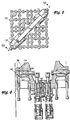
- FIG. 1 is a cross-section of a fuel assembly for a boiling water nuclear reactor in accordance with the present invention.
- the fuel assembly 10 includes a plurality of fuel rods 12, a pair of coolant rods 14 (two coolant rods 14 are illustrated and described in the preferred embodiment, however, a single coolant rod is often used in such fuel assemblies), and a channel 16 surrounding the fuel rods 12 and coolant rods 14.
- the fuel rods 12 are preferably arranged in a 10x10 matrix and are secured against lateral movement in the channel by a plurality of spacers 18.
- the coolant rods 14 are generally centrally disposed in the fuel rod matrix.
- Small holes are provided at both the lower and upper ends of the coolant rods 14 allowing water to be driven through the rod, thus introducing moderating material within the fuel rod matrix.
- One water rod also serves as the spacer-capture rod being mechanically locked to each of the spacers 18, thereby fixing the axial position of each spacer 18.
- the fuel rod spacers 18 are equipped with Inconel-X springs to maintain rod to rod spacing.
- the fuel rods 12 and the coolant rods 14 are supported by a lower tie plate 20.
- An upper tie plate 22 receives the fuel rods 12 and the coolant rods 14 and restricts lateral movement. End plugs of the fuel rods have pins that fit into anchor holes in the tie plates 20, 22. An expansion space located over the top end plug of each fuel rod allows them to expand axially by sliding within the holes in the upper tie plate to accommodate differential axial thermal expansion.
- none of the fuel rods is threaded into the lower tie plate 20 or the upper tie plate 22.
- One or both of the coolant rods 14 may be securely threaded into the lower tie plate 20.
- the coolant rods 14 need not be removed from the bundle nearly as frequently as the fuel rods 12.
- the coolant rods 14 are threaded or otherwise securely attached to the lower tie plate 20.
- a transition member 24 supports the lower tie plate 20 in the channel 16 and serves as a transition to the nose piece 26.
- the channel 16 is secured to the transition member 24 by any suitable structure.
- a bolt 28 is threaded through the channel and into the transition member 24.
- Four bolts 28 are preferably threaded one each through each side of the substantially square cross-section of the channel 16.
- the transition member 24 has corresponding threaded bolt receiving holes 30 in each side of its corresponding square cross-section.
- the bolts 28 are preferably formed of alloy X-750.
- the bail handle assembly 32 includes a bail handle 33 and two boss members 34.
- Figure 3 is a cross-section through line III-III in Figure 2.
- the boss members 34 include a channel 36 formed therein.
- a latch pin 38 is movably disposed in the channel 36.
- a latch pin cap or head 40 is fixed to an outer end of the latch pin 38 and has a first outermost diameter that is configured to be extendible through a latch pin aperture 42 in the channel 16 and a second innermost diameter that is larger than the latch pin aperture 42 in the channel 16 and that serves as a stop surface for the latch pin 38.
- An inside surface of the latch pin cap 40 delimits the channel 36 in the boss members 34.
- a spring 44 is disposed around the latch pin 38 in the channel 36 between the inside surface of the latch pin cap 40 and an end of the channel 36. The spring 44 urges the latch pin 38 to an extended position, engaging the latch pin aperture 42 in the channel 16.
- the channel 16 bears the structural load of the fuel assembly 10.
- the channel 16 has the highest volume to surface area of the components in the fuel assembly 10 and better avoids the effects of corrosion.
- a bolt 43 is disposed between the water rods 14 in an aperture 45 in the upper tie plate 22.
- the bolt 43 extends into a channel 47.
- a substantially cylindrical member 51 is fixed to the end of the bolt 43 and delimits the channel 47.
- a spring 53 is disposed surrounding the bolt 43 in the space delimited by the cylindrical member 51 and the top of the channel 47.
- the spring 53 serves to maintain the upper tie plate 22 spaced from the water rod main spring supports 55 as illustrated in Figure 3.
- the spring 53 urges the upper tie plate 22 upward such that the latch pins engage an upper end of the latch pin apertures 42. Still further, preload forces of the water rod main springs are diverted from the upper tie plate 22.
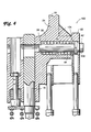
- FIG 4 illustrates a latch pin assembly 100 according to the invention.
- the latch pin assembly 100 enables selective attachment by the latch pin between the upper tie plate 22 and the channel 16 and between the upper tie plate 22 and the coolant rods 14.
- the coolant rods 14 in this embodiment extend farther upward through the upper tie plate 22.
- the latch pin 38 is movable in the channel 36 of the boss member 34, and a spring 44 surrounds the latch pin 38 urging the latch pin toward engagement with the channel.
- An end of the latch pin 38 extends through an aperture 108 in the upper tie plate 22.
- the modified end cap or head 40' of the latch pin 38 includes an anchoring pin 102 extending through the head 40' and radially outwardly from diametrically opposite sides of the head 40'.
- the channel 36 includes two annular grooves 104 that are shaped to receive the anchoring pin 102.
- Figure 6 illustrates the second latch pin position, wherein the anchoring pin is engaged with a second of the grooves 104. At this position, the latch pin is neither engaged with the coolant rod 14 nor the channel 16, and the upper tie plate 20 can be removed from the assembly. In the position illustrated in Figure 4, when the fuel assembly is lifted by the bail handle 33, the entire fuel assembly can be removed from the vessel.
- FIGS 7-10 illustrate an alternative latch pin assembly 200 according to the invention.
- a modified latch pin 38' includes a hook member 202 secured to an end of the latch pin 38' that extends through the aperture 108 in the upper tie plate 22.
- An arm member 204 extends from the end of the latch pin 38', and the hook member 202 is secured to the end of the arm member 204 such that the hook member 202 is disposed offset from a longitudinal axis 206 of the latch pin 38'.
- the hook member 202 can be rotated into and out of engagement with the coolant rod 14.
- the latch pin 38' is rotated by an external tool (not shown).
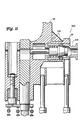
- FIGs 11-14 illustrate yet another alternative latch pin assembly 300 according to the invention.
- the latch pin in this arrangement consists of an outer shaft 302 and an inner shaft 304.
- the outer shaft 302 is disposed in the channel 36 surrounding the inner shaft 304.
- a head portion of the outer shaft 302 includes a recessed area 306 that is adapted to receive the channel 16 of the fuel assembly.
- the outer shaft 302 includes a plurality of holes 308, at least three and preferably about five, evenly spaced about the periphery of the outer shaft 302.
- the holes 308 are configured to receive an anchoring member or ball 310.
- a locking ring 312 is secured to the innermost end of the outer shaft 302, preferably by threads, and provides a shelf for the spring 44.
- the inner shaft 304 includes an engaging shaft portion 314, a transition shaft portion 316 and an inner shaft head 3 18.
- the inner shaft head 318 includes a first diameter section 320, a taper section 322 and a second diameter section 324 having a diameter smaller than the first diameter section 320.
- the taper section 322 is positioned relative to the outer shaft adjacent the holes 308 such that the balls 310 contact the taper section 322.
- the channel 36 includes two annular grooves 326 that are shaped to receive the balls 310.
- the recessed portion 306 of the outer shaft 302 is extended through an aperture in the channel 16 such that the latch pin assembly connects the upper tie plate 22 and the channel 16. Because the spring 44 urges against the inner shaft head 318, the taper section 322 of the inner shaft head drives the balls 310 outwardly into engagement with the grooves 326. As a result, the latch pin assembly 300 is positively secured in the channel engagement position.
- an external tool displaces the inner shaft 304 inwardly against the force of the spring 44.
- the balls 310 are released from their positive engagement in the grooves 326 by virtue of the relative movement of the taper section 322.
- the outer shaft 302 is then driven inwardly by the external tool until the balls 310 are received in the innermost one of the grooves 326.
- the inner shaft 304 is driven through the aperture 328 in the coolant rod 14, thereby engaging the coolant rod 14.
- FIG 13 illustrates still another alternative latch pin assembly 400 according to the invention.
- a modified latch pin 38" is hollow for receiving a tool 402.
- the tool 402 is movable within the latch pin 38" between a fuel assembly channel engaging position, as illustrated in Figure 13, and a coolant rod engaging position.
- the tool 402 may be provided with a handle 404 that is remotely operable. In operation, an operator displaces the tool 402 inwardly to engage the coolant rod 14.
- the tool is of a length such that it simultaneously engages the fuel assembly channel 16 and the coolant rod 14 or only engages the fuel assembly channel 16.
- the tool may be configured such that it is capable of engaging the coolant rod after the bundle is removed from the channel.
- the tool 402 preferably includes structure to lock it in place inside the latch pin 38".
- the components of the latch pin assemblies 100, 200, 300, 400 are preferably formed of Inconel X-750, and the shaped members (e.g., head 40, latch pin 38', inner shaft 304) are preferably machined out of bar stock.
- the shaped members e.g., head 40, latch pin 38', inner shaft 304
- the invention is not meant to be limited to the structure that is illustrated and described.
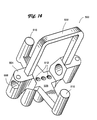
- FIG 14 is a perspective view of an alternative handle assembly according to the invention.
- this handle assembly it is possible to incorporate the latch pin assemblies of the invention into a fuel assembly that does not include an upper tie plate grid that receives the fuel rods.
- An extra spacer 18 (see Figure 1) may be provided in the vicinity of the top of the assembly or the spacers 18 may be spaced farther apart along the fuel assembly.
- the handle assembly 500 includes a bail handle 502 integral with a pair of boss members 504 having channels 506 therein.
- a cross member 508 having a pair of outriggers 510 is configured such that it is substantially perpendicular to the bail handle 502.
- the central plane of the handle assembly 500 is disposed below the plane defined by the longitudinal axis of the channels 506.
- the coolant rods 14 extend upward through the holes 512 in the central plane.
- the latch pin assemblies of the present invention are easily incorporated into the structure of the handle assembly 500.
Abstract

Description
- This invention relates to the structure of a fuel assembly in a boiling water nuclear reactor vessel and, more particularly, to a fuel assembly structure that selectively utilizes the channel and the coolant rod to support its load, thereby eliminating the need for fuel tie rods.
- A conventional fuel assembly in a boiling water nuclear reactor vessel includes a lower tie plate, an upper tie plate and a matrix of sealed fuel rods supported between the upper and lower tie plates. The fuel rods contain nuclear fuel pellets in sealed containment for supporting a required critical reaction for the generation of steam. One or more coolant rods is included in the matrix of the fuel rods and is also supported between the upper and lower tie plates. A channel surrounds the tie plates, fuel rods and coolant rod. This channel is commonly square in cross-section and made of metal (preferably an alloy called Zircaloy). Water passes from the bottom of the fuel assembly to the top of the fuel assembly. Water enters through the lower tie plate within the channel and passes between the upstanding fuel rods. Water and generated steam exit from within the channel between the fuel rods and out through the upper tie plate. The channel confines the required moderator coolant flow to a flow path that is restricted between the tie plates.
- The lower tie plate and the upper tie plate serve to support the sealed fuel rods in the vertical and upstanding matrix. Typically, the upper tie plate forms an overlying matrix of fuel rod support points. Into about eight of these support points are conventionally placed correspondingly male threaded tie rods and fittings. The tie rods, which contain fuel similar to the fuel rods, are threaded at their lower ends for corresponding attachment to the lower tie plate. The lower tie plate similarly forms an underlying matrix of fuel rod support points. These underlying support points correspond for the most part to the overlying support points of the upper tie plate. Conventionally, about eight of these support points are threaded with female apertures, which correspond to the overlying apertures in the upper tie plates. Into these threaded support points in the lower tie plates are placed the lower threaded ends of the fuel tie rods. Thus, conventionally, the two tie plates are tied together with the fuel tie rods.
- The tie plates also define a matrix of apertures for permitting fluid flow into and out of the fuel assembly. Specifically, the lower tie plate defines a first matrix of apertures for permitting the in flow of water coolant. This coolant functions in the capacity of moderating or slowing down reaction produced fast neutrons to produce reaction continuing slow or thermal neutrons. At the same time, as the coolant passes upwardly through the fuel assembly within the channel, a portion of the coolant is turned to steam. This steam and the coolant that is not turned into steam and remains in the liquid phase must pass out through the upper tie plate. Consequently, the upper tie plate forms its own matrix of apertures in between its matrix of fuel rod support points. The upper tie plate matrix of apertures permits the out flow of the two phase steam/water mixture from the fuel assembly.
- The fuel bundle must be periodically replaced and/or inspected during so-called "outages" of a reactor. These outages occur when the central steam generating core of a nuclear reactor has its overlying component removed to provide access through shielding water to the core. During such "outages," sections of the reactor vessel core are removed, inspected and/or replaced. The core, submerged in a radiation quenching bath of water, has the fuel bundles to be replaced for inspection removed by remotely grasping the fuel assembly at a handle. The handle must define, at the top of the fuel assembly, a support point for the entire weight of the fuel assembly in a depending relationship when the assembly is removed from the vessel. Once the fuel assembly is supported at the handle, the entire weight of the fuel assembly is carried through the handle. This weight includes the weight of the fuel and coolant rods, the weight of the upper tie plate, the weight of the lower tie plate and the weight of the surrounding channel (upwards of 600 pounds).
- Once the fuel assembly is removed from the vessel, the tie plates, fuel rods and coolant rods can be separated from the channel. After separation from the channel, the fuel rods can easily be inspected and/or replaced. Conventionally, however, the threaded end plugs of the fuel tie rods tend to seize in their threaded connections, thus making replacement of the fuel tie rods difficult and time consuming. Moreover, as fuel assembly design lifetimes are extended, corrosion effects weaken the fuel tie rods. This weakening occurs due to corrosion thinning of the material and by a reduction in ductility due to the formation of hydrogen and its absorption.
- Thus, there is a need to provide a fuel assembly structure that does not include fuel tie rods threadedly connected between the upper and lower tie plates. Moreover, there is a need to utilize a structural load path for the fuel assembly that is less affected by corrosion effects. In general, since corrosion is a surface phenomena, a structure with a high volume to surface area provides more margin in this regard. Without adding additional structure to the general design of boiling water reactor fuel assemblies, the component with the highest volume to surface area is the channel. A fuel assembly that utilizes the channel to support its load is described in commonly owned copending application serial number (attorney dockets 1585-104), filed on October 12, 1995, the disclosure of which is herein incorporated by reference.
- It would be advantageous to enable the selective use of the channel and the coolant rod to carry the fuel assembly load such that either the entire fuel assembly can be removed from the reactor vessel or only the fuel bundle (i.e., without the channel) can be removed from the reactor vessel.
- The invention therefore seeks to provide a fuel assembly structure that enables selective use of the channel and the coolant rod as the structural member for carrying the fuel assembly load. It also seeks to provide a fuel assembly structure that allows lifting of the assembly through a load path that does not utilize fuel tie rods. Furthermore, the invention also seeks to provide a method of lifting the fuel bundle and the fuel assembly.
- According to a first aspect of the invention, there is provided a latch pin assembly for a tie plate in a boiling water nuclear reactor including a fuel assembly channel surrounding a plurality of fuel rods and at least one coolant rod, the latch pin assembly comprising:
- a latch pin selectively engageable with the fuel assembly channel and the coolant rod; and
- an anchoring assembly cooperating with said latch pin, said anchoring assembly anchoring said latch pin in a selected position such that the latch pin engages at least one of the fuel assembly channel and the coolant rod.
- According to a second aspect of the invention, there is provided a fuel assembly comprising:
- a plurality of fuel rods;
- at least one coolant rod;
- a fuel assembly channel surrounding said plurality of fuel rods and said coolant rod;
- an upper tie plate disposed inside said fuel assembly channel and laterally supporting said fuel rods and said coolant rod; and
- a latch pin assembly selectively engageable with the fuel assembly channel and the coolant rod.
- The latch pin may be alternatively engageable with the fuel assembly channel and the coolant rod or simultaneously engageable with the fuel assembly channel and the coolant rod. The tie plate preferably includes a latch pin channel, and the latch pin is movably disposed in the latch pin channel. The latch pin may be provided with a head delimiting an outer end of the latch pin channel, wherein the assembly further includes a spring disposed between the head and an inner end of the latch pin channel. In this embodiment, the spring urges the latch pin toward a position in engagement with the fuel assembly channel.
- The anchoring assembly may be defined by at least one annular groove formed in the latch pin channel; and an anchoring pin extending through the head and radially outwardly from diametrically opposite sides of the head, wherein the anchoring pin is shaped to be received in the annular groove. In one arrangement, the anchoring assembly includes two annular grooves formed in the latch pin channel. One of the two annular grooves corresponds to a first latch pin position where the latch pin is engaged with the coolant rod, and the other of the two annular grooves corresponds to a second latch pin position where the latch pin is disengaged from the fuel assembly channel and from the coolant rod. The latch pin may be configured to be movable to a third latch pin position where the latch pin is engaged with the fuel assembly channel and where the anchoring pin is not received in either of the two annular grooves.
- The anchoring assembly may alternatively be defined by a hook disposed at an end of the latch pin opposite from the head, wherein the hook is selectively engageable with the coolant rod. In this arrangement, the hook is disposed offset from the longitudinal axis of the latch pin. In addition, the latch pin may be rotatably disposed in the latch pin channel for rotation about the longitudinal axis between an engaged position where the hook is engaged with the coolant rod and a disengaged position where the hook is disengaged with the coolant rod. Still further, the latch pin may be extendible through an aperture through the inner end of the latch pin channel, wherein the hook is fixed to the end opposite from the head extended through the aperture. In this arrangement, the anchoring assembly additionally includes a stop surface, wherein in the disengaged position, the hook abuts the stop surface.
- The latch pin may be provided with an inner shaft movably disposed in the latch pin channel and an outer shaft surrounding the inner shaft and movably disposed in the latch pin channel, wherein the inner shaft is movable relative to the outer shaft. In this arrangement, the anchoring assembly is defined by at least one annular groove formed in the latch pin channel; an aperture formed in the outer shaft; and an anchoring member disposed in the aperture and engageable with the annular groove and the inner shaft. The anchoring member may be a ball, and the anchoring assembly may include two annular grooves formed in the latch pin channel, wherein one of the two annular grooves corresponds to a first latch pin position where the latch pin is engaged with the coolant rod, and the other of the two annular grooves corresponds to a second latch pin position where the latch pin is engaged with the fuel assembly channel. The inner shaft may include an engaging shaft portion engageable with the coolant rod, a transition shaft portion and an inner shaft head. The inner shaft head has a first diameter section, a tapering diameter section and a second diameter section, smaller than the first diameter section, wherein the anchoring member engages the inner shaft at the tapering diameter section of the inner shaft head. The latch pin may further be provided with a locking ring secured to an inside end of the outer shaft and defining a shelf inside the outer shaft, wherein the latch pin assembly further includes a spring disposed between the shelf and the first diameter section of the inner shaft head that urges the latch pin toward a position in engagement with the fuel assembly channel. The outer shaft may include an outer shaft head engageable with the fuel assembly channel, having a first innermost diameter, a second intermediate diameter smaller than the first innermost diameter, and a third outermost diameter larger than the second intermediate diameter.
- In accordance with another aspect of the invention, there is provided a fuel assembly including a plurality of fuel rods; at least one coolant rod; a fuel assembly channel surrounding the plurality of fuel rods and the coolant rod; an upper tie plate disposed inside the fuel assembly channel and laterally supporting the fuel rods and the coolant rod; and a latch pin assembly selectively engageable with the fuel assembly channel and the coolant rod.
- The latch pin assembly may include a latch pin, and the coolant rod may include an engaging aperture configured to receive the latch pin. The latch pin assembly may be further provided with an anchoring assembly cooperating with the latch pin, which anchors the latch pin in a selected position such that the latch pin engages at least one of the fuel assembly channel and the coolant rod. The latch pin may be alternatively engageable with the fuel assembly channel and the coolant rod or simultaneously engageable with the fuel assembly channel and the coolant rod. The tie plate may include a latch pin channel, wherein the latch pin is movably disposed in the latch pin channel. The latch pin may be provided with a head delimiting an outer end of the latch pin channel, wherein the latch pin assembly additionally includes a spring disposed between the head and an inner end of the latch pin channel that urges the latch pin toward a position in engagement with the fuel assembly channel.
- Suitably, the latch pin may be formed of Inconel X-750.
- According to a third aspect of the invention there is provided a method of lifting a fuel assembly in a boiling water nuclear reactor, the fuel assembly including a plurality of fuel rods, at least one coolant rod, a fuel assembly channel surrounding the plurality of fuel rods and the coolant rod, an upper tie plate disposed inside the fuel assembly channel and laterally supporting the fuel rods and the coolant rod, and a latch pin assembly selectively engageable with the fuel assembly channel and the coolant rod, the method comprising :
- enabling the latch pin assembly to selectively engage the fuel assembly channel and the coolant rod;
- anchoring the latch pin in a selected position such that the latch pin engages at least one of the fuel assembly channel and the coolant rod; and
- lifting the fuel assembly through the upper tie plate.
- The invention will now be described in greater detail, by way of example, with reference to the drawings in which:
- Figure 1 is a cross-sectional view of a fuel assembly according to the invention;
- Figure 2 is a view along line II-II in Figure 1;
- Figure 3 is a cross-sectional view through line III-III in Figure 2;
- Figure 4 illustrates a latch pin assembly according to the invention;
- Figure 5 illustrates the latch pin assembly engaging the coolant rod;
- Figure 6 illustrates the latch pin assembly in a neutral position;
- Figure 7 illustrates an alternative latch pin assembly according to the invention;
- Figure 8 is a top view of the latch pin assembly of Figure 7;
- Figure 9 illustrates the Figure 7 latch pin assembly engaging the fuel assembly channel;
- Figure 10 is a top view of the latch pin assembly in Figure 9;
- Figure 11 illustrates another alternative latch pin assembly according to the invention;
- Figure 12 illustrates the Figure 11 latch pin assembly engaging the fuel assembly channel;
- Figure 13 illustrates still another alternative latch assembly according to the invention; and
- Figure 14 is a perspective view of an alternative handle assembly according to the invention.
- Figure 1 is a cross-section of a fuel assembly for a boiling water nuclear reactor in accordance with the present invention. The
fuel assembly 10 includes a plurality of fuel rods 12, a pair of coolant rods 14 (twocoolant rods 14 are illustrated and described in the preferred embodiment, however, a single coolant rod is often used in such fuel assemblies), and achannel 16 surrounding the fuel rods 12 andcoolant rods 14. The fuel rods 12 are preferably arranged in a 10x10 matrix and are secured against lateral movement in the channel by a plurality of spacers 18. Thecoolant rods 14 are generally centrally disposed in the fuel rod matrix. Small holes are provided at both the lower and upper ends of thecoolant rods 14 allowing water to be driven through the rod, thus introducing moderating material within the fuel rod matrix. One water rod also serves as the spacer-capture rod being mechanically locked to each of the spacers 18, thereby fixing the axial position of each spacer 18. The fuel rod spacers 18 are equipped with Inconel-X springs to maintain rod to rod spacing. - The fuel rods 12 and the
coolant rods 14 are supported by alower tie plate 20. Anupper tie plate 22 receives the fuel rods 12 and thecoolant rods 14 and restricts lateral movement. End plugs of the fuel rods have pins that fit into anchor holes in thetie plates lower tie plate 20 or theupper tie plate 22. One or both of thecoolant rods 14 may be securely threaded into thelower tie plate 20. As discussed above in connection with the prior art, it is not desirable to thread anything into thetie plates coolant rods 14 need not be removed from the bundle nearly as frequently as the fuel rods 12. Thus, in the present invention, thecoolant rods 14 are threaded or otherwise securely attached to thelower tie plate 20. - A
transition member 24 supports thelower tie plate 20 in thechannel 16 and serves as a transition to thenose piece 26. Thechannel 16 is secured to thetransition member 24 by any suitable structure. In the illustrated embodiment, abolt 28 is threaded through the channel and into thetransition member 24. Fourbolts 28 are preferably threaded one each through each side of the substantially square cross-section of thechannel 16. Thetransition member 24 has corresponding threadedbolt receiving holes 30 in each side of its corresponding square cross-section. Thebolts 28 are preferably formed of alloy X-750. - Integral with the
upper tie plate 22 is abail handle assembly 32. Referring to Figures 1 and 2, thebail handle assembly 32 includes abail handle 33 and twoboss members 34. Figure 3 is a cross-section through line III-III in Figure 2. Theboss members 34 include achannel 36 formed therein. Alatch pin 38 is movably disposed in thechannel 36. A latch pin cap orhead 40 is fixed to an outer end of thelatch pin 38 and has a first outermost diameter that is configured to be extendible through alatch pin aperture 42 in thechannel 16 and a second innermost diameter that is larger than thelatch pin aperture 42 in thechannel 16 and that serves as a stop surface for thelatch pin 38. An inside surface of thelatch pin cap 40 delimits thechannel 36 in theboss members 34. Aspring 44 is disposed around thelatch pin 38 in thechannel 36 between the inside surface of thelatch pin cap 40 and an end of thechannel 36. Thespring 44 urges thelatch pin 38 to an extended position, engaging thelatch pin aperture 42 in thechannel 16. - In operation, because the
transition member 24 is rigidly secured to thechannel 16 by means of thebolt 28 and because thelatch pin 38 is inserted into thelatch pin aperture 42 in thechannel 16, when lifting thefuel assembly 10 with thebail handle assembly 32, thechannel 16 bears the structural load of thefuel assembly 10. As noted above, thechannel 16 has the highest volume to surface area of the components in thefuel assembly 10 and better avoids the effects of corrosion. - With continued reference to Figure 3, a
bolt 43 is disposed between thewater rods 14 in anaperture 45 in theupper tie plate 22. Thebolt 43 extends into achannel 47. A substantiallycylindrical member 51 is fixed to the end of thebolt 43 and delimits thechannel 47. A spring 53 is disposed surrounding thebolt 43 in the space delimited by thecylindrical member 51 and the top of thechannel 47. The spring 53 serves to maintain theupper tie plate 22 spaced from the water rod main spring supports 55 as illustrated in Figure 3. Moreover, the spring 53 urges theupper tie plate 22 upward such that the latch pins engage an upper end of thelatch pin apertures 42. Still further, preload forces of the water rod main springs are diverted from theupper tie plate 22. - Figure 4 illustrates a
latch pin assembly 100 according to the invention. Thelatch pin assembly 100 enables selective attachment by the latch pin between theupper tie plate 22 and thechannel 16 and between theupper tie plate 22 and thecoolant rods 14. Referring to Figure 4, thecoolant rods 14 in this embodiment extend farther upward through theupper tie plate 22. Similar to the embodiment illustrated in Figure 3, thelatch pin 38 is movable in thechannel 36 of theboss member 34, and aspring 44 surrounds thelatch pin 38 urging the latch pin toward engagement with the channel. An end of thelatch pin 38 extends through anaperture 108 in theupper tie plate 22. - The modified end cap or head 40' of the
latch pin 38 includes ananchoring pin 102 extending through the head 40' and radially outwardly from diametrically opposite sides of the head 40'. Thechannel 36 includes twoannular grooves 104 that are shaped to receive theanchoring pin 102. - In the position shown in Figure 4, the anchoring
pin 102 is disengaged from thegrooves 104 of thechannel 36. Thus, thespring 44 urges thelatch pin 38 to its outermost position in engagement with the channel. Referring to Figure 5, when thelatch pin 38 is driven inwardly, preferably by an external tool (not shown), the latch pin shaft extends through anaperture 106 in thecoolant rod 14. When theanchoring pin 102 is aligned with the innermost of the twogrooves 104, the external tool then rotates thelatch pin 38 approximately 90° until theanchoring pin 102 is received in the groove. In this position, when lifting the fuel assembly by thebail handle 33, the fuel bundle can be removed from the vessel, and the channel will remain in place. The position illustrated in Figure 5 is denoted as the first latch pin position. - Figure 6 illustrates the second latch pin position, wherein the anchoring pin is engaged with a second of the
grooves 104. At this position, the latch pin is neither engaged with thecoolant rod 14 nor thechannel 16, and theupper tie plate 20 can be removed from the assembly. In the position illustrated in Figure 4, when the fuel assembly is lifted by thebail handle 33, the entire fuel assembly can be removed from the vessel. - Figures 7-10 illustrate an alternative
latch pin assembly 200 according to the invention. In this arrangement, a modified latch pin 38' includes ahook member 202 secured to an end of the latch pin 38' that extends through theaperture 108 in theupper tie plate 22. Anarm member 204 extends from the end of the latch pin 38', and thehook member 202 is secured to the end of thearm member 204 such that thehook member 202 is disposed offset from alongitudinal axis 206 of the latch pin 38'. As a result, thehook member 202 can be rotated into and out of engagement with thecoolant rod 14. The latch pin 38' is rotated by an external tool (not shown). - In this configuration, when the
hook member 202 is engaged with thecoolant rod 14, thehead 40 is maintained withdrawn from the channel. Thus, when the assembly is lifted by thebail handle 33, the fuel bundle can be removed from the reactor vessel without thechannel 16. Referring to Figures 9 and 10, thehook member 202 is disengaged from thecoolant rod 14 by rotating the latch pin with the external tool. When thehook member 202 is released from engagement, aspring 44 urges the latch pin outwardly so that thehead 40 engages the channel 16(Figure 9). In this position, when the assembly is lifted by thebail handle 33, the entire fuel assembly can be removed from the reactor vessel. Asurface 208 acts as a stop surface for thehook member 202 when thelatch pin 38 is engaged with the channel. In addition, in its disengaged position, thehook member 202 does not contact the water rod (see Figure 10). - Figures 11-14 illustrate yet another alternative
latch pin assembly 300 according to the invention. Referring to Figure 11, the latch pin in this arrangement consists of anouter shaft 302 and aninner shaft 304. Theouter shaft 302 is disposed in thechannel 36 surrounding theinner shaft 304. A head portion of theouter shaft 302 includes a recessedarea 306 that is adapted to receive thechannel 16 of the fuel assembly. Theouter shaft 302 includes a plurality ofholes 308, at least three and preferably about five, evenly spaced about the periphery of theouter shaft 302. Theholes 308 are configured to receive an anchoring member orball 310. A lockingring 312 is secured to the innermost end of theouter shaft 302, preferably by threads, and provides a shelf for thespring 44. - The
inner shaft 304 includes an engagingshaft portion 314, atransition shaft portion 316 and an inner shaft head 3 18. Theinner shaft head 318 includes afirst diameter section 320, ataper section 322 and asecond diameter section 324 having a diameter smaller than thefirst diameter section 320. Thetaper section 322 is positioned relative to the outer shaft adjacent theholes 308 such that theballs 310 contact thetaper section 322. Thechannel 36 includes twoannular grooves 326 that are shaped to receive theballs 310. - In the position illustrated in Figure 11, the recessed
portion 306 of theouter shaft 302 is extended through an aperture in thechannel 16 such that the latch pin assembly connects theupper tie plate 22 and thechannel 16. Because thespring 44 urges against theinner shaft head 318, thetaper section 322 of the inner shaft head drives theballs 310 outwardly into engagement with thegrooves 326. As a result, thelatch pin assembly 300 is positively secured in the channel engagement position. - To move the latch pin assembly so that it disengages from the channel and engages the coolant rod, an external tool displaces the
inner shaft 304 inwardly against the force of thespring 44. As a result, theballs 310 are released from their positive engagement in thegrooves 326 by virtue of the relative movement of thetaper section 322. Theouter shaft 302 is then driven inwardly by the external tool until theballs 310 are received in the innermost one of thegrooves 326. In this configuration, illustrated in Figure 12, theinner shaft 304 is driven through theaperture 328 in thecoolant rod 14, thereby engaging thecoolant rod 14. Thus, if the assembly is lifted with thebail handle 33, the fuel bundle can be removed from the reactor vessel without the channel. - Figure 13 illustrates still another alternative
latch pin assembly 400 according to the invention. In this configuration, a modifiedlatch pin 38" is hollow for receiving atool 402. Thetool 402 is movable within thelatch pin 38" between a fuel assembly channel engaging position, as illustrated in Figure 13, and a coolant rod engaging position. Thetool 402 may be provided with ahandle 404 that is remotely operable. In operation, an operator displaces thetool 402 inwardly to engage thecoolant rod 14. The tool is of a length such that it simultaneously engages thefuel assembly channel 16 and thecoolant rod 14 or only engages thefuel assembly channel 16. The tool may be configured such that it is capable of engaging the coolant rod after the bundle is removed from the channel. Thetool 402 preferably includes structure to lock it in place inside thelatch pin 38". - The components of the
latch pin assemblies head 40, latch pin 38', inner shaft 304) are preferably machined out of bar stock. Of course, those of ordinary skill in the art may contemplate other materials and methods of forming the components, and the invention is not meant to be limited to the structure that is illustrated and described. - Figure 14 is a perspective view of an alternative handle assembly according to the invention. With this handle assembly, it is possible to incorporate the latch pin assemblies of the invention into a fuel assembly that does not include an upper tie plate grid that receives the fuel rods. An extra spacer 18 (see Figure 1) may be provided in the vicinity of the top of the assembly or the spacers 18 may be spaced farther apart along the fuel assembly.
- The
handle assembly 500 includes abail handle 502 integral with a pair ofboss members 504 havingchannels 506 therein. Across member 508 having a pair ofoutriggers 510 is configured such that it is substantially perpendicular to thebail handle 502. As illustrated in Figure 14, the central plane of thehandle assembly 500 is disposed below the plane defined by the longitudinal axis of thechannels 506. Thecoolant rods 14 extend upward through theholes 512 in the central plane. The latch pin assemblies of the present invention are easily incorporated into the structure of thehandle assembly 500. - While the invention has been described in connection with what is presently considered to be the most practical and preferred embodiments, it is to be understood that the invention is not to be limited to the disclosed embodiments, but on the contrary, is intended to cover various modifications and equivalent arrangements included within the spirit and scope of the appended claims.
Claims (22)
- A latch pin assembly for a tie plate in a boiling water nuclear reactor including a fuel assembly channel surrounding a plurality of fuel rods and at least one coolant rod, the latch pin assembly comprising:a latch pin selectively engageable with the fuel assembly channel and the coolant rod; andan anchoring assembly cooperating with said latch pin, said anchoring assembly anchoring said latch pin in a selected position such that the latch pin engages at least one of the fuel assembly channel and the coolant rod.
- A fuel assembly comprising:a plurality of fuel rods;at least one coolant rod;a fuel assembly channel surrounding said plurality of fuel rods and said coolant rod;an upper tie plate disposed inside said fuel assembly channel and laterally supporting said fuel rods and said coolant rod; anda latch pin assembly selectively engageable with the fuel assembly channel and the coolant rod.
- An assembly according to claim 2, wherein said latch pin assembly comprises a latch pin, and wherein said coolant rod comprises an engaging aperture configured to receive said latch pin.
- An assembly according to claim 3, wherein said latch pin assembly further comprises an anchoring assembly cooperating with said latch pin, said anchoring assembly anchoring said latch pin in a selected position such that the latch pin engages at least one of the fuel assembly channel and the coolant rod.
- An assembly according to claim 1 or 4, wherein said latch pin is alternatively engageable with the fuel assembly channel and the coolant rod.
- An assembly according to claim 1 or 4, wherein said latch pin is simultaneously engageable with the fuel assembly channel and the coolant rod.
- An assembly according to claim 1 or 4, wherein said tie plate includes a latch pin channel, in which said latch pin is movably disposed.
- An assembly according to claim 7, wherein said latch pin comprises a head delimiting an outer end of said latch pin channel, the assembly further comprising a spring disposed between said head and an inner end of said latch pin channel, said spring urging said latch pin toward a position in engagement with said fuel assembly channel.
- An assembly according to claim 8, wherein said anchoring assembly comprises:at least one annular groove formed in said latch pin channel; andan anchoring pin extending through said head and radially outwardly from diametrically opposite sides of said head, said anchoring pin being shaped to be received in said at least one annular groove.
- An assembly according to claim 8 or 9, said anchoring assembly comprising two annular grooves formed in said latch pin channel, one of said two annular grooves corresponding to a first latch pin position where said latch pin is engaged with said coolant rod, and the other of said two annular grooves corresponding to a second latch pin position where said latch pin is disengaged from said fuel assembly channel and from said coolant rod.
- An assembly according to claim 10, wherein said latch pin is configured to be movable to a third latch pin position where said latch pin is engaged with said fuel assembly channel and where said anchoring pin is not received in either of said two annular grooves.
- An assembly according to claim 8, wherein said anchoring assembly comprises a hook disposed at an end of said latch pin opposite to said head, wherein said hook is selectively engageable with the coolant rod.
- A latch pin assembly according to claim 12, wherein said latch pin comprises a longitudinal axis, said hook being disposed offset from said longitudinal axis.
- An assembly according to claim 13, wherein said latch pin is rotatably disposed in said latch pin channel for rotation about said longitudinal axis between an engaged position where said hook is engaged with said coolant rod and a disengaged position where said hook is disengaged with said coolant rod.
- An assembly according to claim 14, wherein said latch pin is extendible through an aperture through said inner end of said latch pin channel, and wherein said hook is fixed to said end opposite from said head extended through said aperture, said anchoring assembly further comprising a stop surface, wherein in said disengaged position, said hook abuts said stop surface.
- An assembly according to claim 7, wherein said latch pin comprises an inner shaft movably disposed in said latch pin channel and an outer shaft surrounding said inner shaft and movably disposed in said latch pin channel, said inner shaft being movable relative to said outer shaft.
- An assembly according to claim 16, wherein said anchoring assembly comprises:at least one annular groove formed in said latch pin channel;an aperture formed in said outer shaft; andan anchoring member disposed in said aperture and engageable with said at least one annular groove and said inner shaft.
- A latch pin assembly according to claim 17, wherein said anchoring member is a ball, and wherein said anchoring assembly comprises two annular grooves formed in said latch pin channel, one of said two annular grooves corresponding to a first latch pin position where said latch pin is engaged with said coolant rod, and the other of said two annular grooves corresponding to a second latch pin position where said latch pin is engaged with said fuel assembly channel.
- A latch pin assembly according to claim 17, wherein said inner shaft comprises an engaging shaft portion engageable with the coolant rod, a transition shaft portion and an inner shaft head, said inner shaft head comprising a first diameter section, a tapering diameter section and a second diameter section, smaller than said first diameter section, said anchoring member engaging said inner shaft at said tapering diameter section of said inner shaft head.
- A latch pin assembly according to claim 19, wherein said latch pin further comprises a locking ring secured to an inside end of said outer shaft and defining a shelf inside said outer shaft, the latch pin assembly further comprising a spring disposed between said shelf and said first diameter section of said inner shaft head, said spring urging said latch pin toward a position in engagement with said fuel assembly channel.
- A latch pin according to claim 16, wherein said outer shaft comprises an outer shaft head engageable with the fuel assembly channel, said outer shaft head having a first innermost diameter, a second intermediate diameter smaller than said first innermost diameter, and a third outermost diameter larger than said second intermediate diameter.
- A method of lifting a fuel assembly in a boiling water nuclear reactor, the fuel assembly including a plurality of fuel rods, at least one coolant rod, a fuel assembly channel surrounding the plurality of fuel rods and the coolant rod, an upper tie plate disposed inside the fuel assembly channel and laterally supporting the fuel rods and the coolant rod, and a latch pin assembly selectively engageable with the fuel assembly channel and the coolant rod, the method comprising:enabling the latch pin assembly to selectively engage the fuel assembly channel and the coolant rod;anchoring the latch pin in a selected position such that the latch pin engages at least one of the fuel assembly channel and the coolant rod; andlifting the fuel assembly through the upper tie plate.
Applications Claiming Priority (2)
| Application Number | Priority Date | Filing Date | Title |
|---|---|---|---|
| US551769 | 1990-07-11 | ||
| US08/551,769 US5748695A (en) | 1995-11-07 | 1995-11-07 | Fuel assembly structure selectively using channel and coolant rod for load support and method |
Publications (2)
| Publication Number | Publication Date |
|---|---|
| EP0773553A1 true EP0773553A1 (en) | 1997-05-14 |
| EP0773553B1 EP0773553B1 (en) | 2001-09-12 |
Family
ID=24202609
Family Applications (1)
| Application Number | Title | Priority Date | Filing Date |
|---|---|---|---|
| EP96307999A Expired - Lifetime EP0773553B1 (en) | 1995-11-07 | 1996-11-05 | Fuel assembly structure selectively using channel and coolant rod for load support and method of lifting the fuel assembly |
Country Status (4)
| Country | Link |
|---|---|
| US (1) | US5748695A (en) |
| EP (1) | EP0773553B1 (en) |
| JP (1) | JP3742698B2 (en) |
| DE (1) | DE69615124T2 (en) |
Cited By (1)
| Publication number | Priority date | Publication date | Assignee | Title |
|---|---|---|---|---|
| EP0797216A1 (en) * | 1996-03-19 | 1997-09-24 | General Electric Company | Method and apparatus for attaching a lifting bar to a load bearing water rod in a nuclear fuel assembly |
Families Citing this family (5)
| Publication number | Priority date | Publication date | Assignee | Title |
|---|---|---|---|---|
| SE508875C2 (en) * | 1997-03-11 | 1998-11-09 | Asea Atom Ab | Device and method for locking rods in the bottom plate of a fuel assembly |
| US7139353B2 (en) * | 2002-12-06 | 2006-11-21 | Framatome Anp Inc. | Boiling water reactor nuclear fuel assembly lifting support |
| US8317035B2 (en) * | 2004-12-30 | 2012-11-27 | Global Nuclear Fuel-Americas, Llc. | Debris filter |
| EP3968341A1 (en) * | 2020-09-14 | 2022-03-16 | Framatome | Nuclear fuel assembly for a boiling water reactor with redundant load chain |
| US20230091913A1 (en) * | 2021-09-21 | 2023-03-23 | Framatome | Bwr nuclear fuel assembly comprising an interaction device between a lower tie plate and a fuel channel |
Citations (5)
| Publication number | Priority date | Publication date | Assignee | Title |
|---|---|---|---|---|
| US4560532A (en) * | 1982-04-15 | 1985-12-24 | Westinghouse Electric Corp. | Nuclear fuel assembly |
| US5327471A (en) * | 1990-02-28 | 1994-07-05 | Siemens Aktiengesellschaft | Nuclear reactor fuel assembly with a supporting coolant tube |
| US5339342A (en) * | 1992-01-09 | 1994-08-16 | Siemens Aktiengesellschaft | Fuel assembly for a boiling water reactor with a redundant support structure and a locked fuel assembly case |
| US5481579A (en) * | 1995-01-30 | 1996-01-02 | General Electric Company | Latching and lifting mechanism for a nuclear reactor fuel bundle |
| WO1996003752A1 (en) * | 1994-07-22 | 1996-02-08 | Siemens Aktiengesellschaft | Fuel rod assembly put together by means of pegs |
Family Cites Families (27)
| Publication number | Priority date | Publication date | Assignee | Title |
|---|---|---|---|---|
| US3015616A (en) * | 1956-11-02 | 1962-01-02 | Westinghouse Electric Corp | Rod type fuel assembly |
| GB923343A (en) * | 1959-08-17 | 1963-04-10 | Atomic Energy Authority Uk | Improvements in or relating to nuclear reactor fuel elements |
| US3344036A (en) * | 1964-09-29 | 1967-09-26 | Atomic Energy Authority Uk | Nuclear reactor fuel element assemblies |
| US3366546A (en) * | 1965-12-02 | 1968-01-30 | Combustion Eng | Nuclear reactor |
| US3379619A (en) * | 1966-05-25 | 1968-04-23 | Westinghouse Electric Corp | Fuel assembly for nuclear reactors |
| SE312870B (en) * | 1967-07-17 | 1969-07-28 | Asea Ab | |
| US3697376A (en) * | 1969-08-15 | 1972-10-10 | Gen Electric | Nuclear fuel assembly with flow channel restraining means |
| US3992259A (en) * | 1973-06-25 | 1976-11-16 | Combustion Engineering, Inc. | Fuel assembly for a nuclear reactor |
| US4038137A (en) * | 1973-09-26 | 1977-07-26 | Exxon Nuclear Company, Inc. | Locking means for fuel bundles |
| FR2465295A1 (en) * | 1979-09-06 | 1981-03-20 | Commissariat Energie Atomique | ANTI-ENVOL DEVICE FOR NUCLEAR REACTOR COMBUSTIBLE ELEMENT |
| US4418036A (en) * | 1980-12-16 | 1983-11-29 | Westinghouse Electric Corp. | Fuel assembly for a nuclear reactor |
| SE424929B (en) * | 1980-12-19 | 1982-08-16 | Asea Atom Ab | FUEL CARTRIDGE INTENDED FOR A COOK WATER REACTOR |
| US4578241A (en) * | 1981-05-15 | 1986-03-25 | Ab Asea-Atom | Earthquake-proof fuel assembly |
| US4666664A (en) * | 1982-04-15 | 1987-05-19 | Westinghouse Electric Corp. | Coolant flow paths within a nuclear fuel assembly |
| SE431691B (en) * | 1982-07-12 | 1984-02-20 | Asea Atom Ab | KERNBRENSLEPATRON |
| SE433986B (en) * | 1982-07-12 | 1984-06-25 | Asea Atom Ab | KERNBRENSLEPATRON |
| SE437738B (en) * | 1983-08-04 | 1985-03-11 | Asea Atom Ab | FUEL PATTERN FOR A COOK WATER REACTOR |
| US4652426A (en) * | 1984-08-20 | 1987-03-24 | Westinghouse Electric Corp. | Water tubes arranged in cross-like pattern in a fuel assembly |
| US4683117A (en) * | 1985-09-09 | 1987-07-28 | Westinghouse Electric Corp. | Nuclear fuel assembly incorporating primary and secondary structural support members |
| DE3533317A1 (en) * | 1985-09-18 | 1987-03-26 | Kraftwerk Union Ag | Nuclear reactor fuel element |
| SE450177B (en) * | 1985-10-16 | 1987-06-09 | Asea Atom Ab | KERNBRENSLEPATRON |
| SE454822B (en) * | 1986-04-29 | 1988-05-30 | Asea Atom Ab | NUCLEAR FUEL CARTRIDGE FOR A NUCLEAR REACTOR |
| SE459053B (en) * | 1987-09-28 | 1989-05-29 | Asea Atom Ab | TOP SUPPORT FOR A FIXING AND LOADING OF A TOP SUPPORT FOR A LIFT HANDLE ON A NUCLEAR BRAKE CARTRIDGE |
| US5436946A (en) * | 1994-06-20 | 1995-07-25 | General Electric Company | Spring retention of upper tie plate and fuel bundle channel in a nuclear reactor assembly |
| US5627866A (en) * | 1995-10-12 | 1997-05-06 | General Electric Company | Fuel assembly structure using channel for load support |
| US5646973A (en) * | 1995-10-12 | 1997-07-08 | General Electric Company | BWR fuel assembly without upper tie plate |
| US5610961A (en) * | 1995-10-12 | 1997-03-11 | General Electric Company | Fuel assembly structure using channel for load support |
-
1995
- 1995-11-07 US US08/551,769 patent/US5748695A/en not_active Expired - Lifetime
-
1996
- 1996-11-05 EP EP96307999A patent/EP0773553B1/en not_active Expired - Lifetime
- 1996-11-05 JP JP29217396A patent/JP3742698B2/en not_active Expired - Fee Related
- 1996-11-05 DE DE69615124T patent/DE69615124T2/en not_active Expired - Fee Related
Patent Citations (5)
| Publication number | Priority date | Publication date | Assignee | Title |
|---|---|---|---|---|
| US4560532A (en) * | 1982-04-15 | 1985-12-24 | Westinghouse Electric Corp. | Nuclear fuel assembly |
| US5327471A (en) * | 1990-02-28 | 1994-07-05 | Siemens Aktiengesellschaft | Nuclear reactor fuel assembly with a supporting coolant tube |
| US5339342A (en) * | 1992-01-09 | 1994-08-16 | Siemens Aktiengesellschaft | Fuel assembly for a boiling water reactor with a redundant support structure and a locked fuel assembly case |
| WO1996003752A1 (en) * | 1994-07-22 | 1996-02-08 | Siemens Aktiengesellschaft | Fuel rod assembly put together by means of pegs |
| US5481579A (en) * | 1995-01-30 | 1996-01-02 | General Electric Company | Latching and lifting mechanism for a nuclear reactor fuel bundle |
Cited By (1)
| Publication number | Priority date | Publication date | Assignee | Title |
|---|---|---|---|---|
| EP0797216A1 (en) * | 1996-03-19 | 1997-09-24 | General Electric Company | Method and apparatus for attaching a lifting bar to a load bearing water rod in a nuclear fuel assembly |
Also Published As
| Publication number | Publication date |
|---|---|
| EP0773553B1 (en) | 2001-09-12 |
| DE69615124D1 (en) | 2001-10-18 |
| DE69615124T2 (en) | 2002-06-13 |
| JPH09184894A (en) | 1997-07-15 |
| JP3742698B2 (en) | 2006-02-08 |
| US5748695A (en) | 1998-05-05 |
Similar Documents
| Publication | Publication Date | Title |
|---|---|---|
| US10878970B2 (en) | Nuclear reactor refueling methods and apparatuses | |
| US7453972B2 (en) | Nuclear fuel assembly control rod drive thimble to bottom nozzle connector | |
| US3853703A (en) | Fuel assembly hold-up device | |
| JP6535741B2 (en) | SFR nuclear reactor fuel assembly having a housing including a removably secured upper neutron shielding device | |
| US4323428A (en) | Reconstitutable fuel assembly for a nuclear reactor | |
| US4418036A (en) | Fuel assembly for a nuclear reactor | |
| US4420458A (en) | Nuclear fuel assembly with coolant conducting tube | |
| EP2073214B1 (en) | Fuel Rods Having Irradiation Target End Pieces | |
| US4381284A (en) | Fuel assembly for a nuclear reactor | |
| US5627866A (en) | Fuel assembly structure using channel for load support | |
| EP0773553B1 (en) | Fuel assembly structure selectively using channel and coolant rod for load support and method of lifting the fuel assembly | |
| US6047037A (en) | Multi-lift tool and method for moving control rods in a nuclear reactor | |
| US4716018A (en) | End plug with truncated tapered leading end configuration | |
| US4842815A (en) | Device for locking a guide ring on a plate having an orifice and its use for a guide tube of a nuclear reactor | |
| EP0768677B1 (en) | Fuel assembly structure using channel for load support and method for removing a fuel bundle from the channel | |
| US4683117A (en) | Nuclear fuel assembly incorporating primary and secondary structural support members | |
| JPH0458911B2 (en) | ||
| US20090257545A1 (en) | Reinforcement for a nuclear fuel assembly | |
| EP1568047B1 (en) | Boiling water reactor nuclear fuel assembly lifting support | |
| Walters et al. | Observations of dilation and bowing in Experimental Breeder Reactor II ducts and cladding | |
| EP1213725B1 (en) | Ring plate around openings in reinforced concrete containment vessel | |
| EP0363710A2 (en) | Combined support column and guide tube for use in a nuclear reactor | |
| JPH04301794A (en) | Control rod and control rod guide tube and attaching and detaching method of control rod |
Legal Events
| Date | Code | Title | Description |
|---|---|---|---|
| PUAI | Public reference made under article 153(3) epc to a published international application that has entered the european phase |
Free format text: ORIGINAL CODE: 0009012 |
|
| AK | Designated contracting states |
Kind code of ref document: A1 Designated state(s): DE SE |
|
| 17P | Request for examination filed |
Effective date: 19971114 |
|
| 17Q | First examination report despatched |
Effective date: 19990217 |
|
| GRAG | Despatch of communication of intention to grant |
Free format text: ORIGINAL CODE: EPIDOS AGRA |
|
| GRAG | Despatch of communication of intention to grant |
Free format text: ORIGINAL CODE: EPIDOS AGRA |
|
| GRAH | Despatch of communication of intention to grant a patent |
Free format text: ORIGINAL CODE: EPIDOS IGRA |
|
| GRAH | Despatch of communication of intention to grant a patent |
Free format text: ORIGINAL CODE: EPIDOS IGRA |
|
| GRAA | (expected) grant |
Free format text: ORIGINAL CODE: 0009210 |
|
| AK | Designated contracting states |
Kind code of ref document: B1 Designated state(s): DE SE |
|
| REF | Corresponds to: |
Ref document number: 69615124 Country of ref document: DE Date of ref document: 20011018 |
|
| PLBE | No opposition filed within time limit |
Free format text: ORIGINAL CODE: 0009261 |
|
| STAA | Information on the status of an ep patent application or granted ep patent |
Free format text: STATUS: NO OPPOSITION FILED WITHIN TIME LIMIT |
|
| 26N | No opposition filed | ||
| PGFP | Annual fee paid to national office [announced via postgrant information from national office to epo] |
Ref country code: SE Payment date: 20071128 Year of fee payment: 12 |
|
| PGFP | Annual fee paid to national office [announced via postgrant information from national office to epo] |
Ref country code: DE Payment date: 20071221 Year of fee payment: 12 |
|
| EUG | Se: european patent has lapsed | ||
| PG25 | Lapsed in a contracting state [announced via postgrant information from national office to epo] |
Ref country code: DE Free format text: LAPSE BECAUSE OF NON-PAYMENT OF DUE FEES Effective date: 20090603 |
|
| PG25 | Lapsed in a contracting state [announced via postgrant information from national office to epo] |
Ref country code: SE Free format text: LAPSE BECAUSE OF NON-PAYMENT OF DUE FEES Effective date: 20081106 |