EP0773038A2 - Improved graphic interface for pacemaker programmers - Google Patents
Improved graphic interface for pacemaker programmers Download PDFInfo
- Publication number
- EP0773038A2 EP0773038A2 EP96307877A EP96307877A EP0773038A2 EP 0773038 A2 EP0773038 A2 EP 0773038A2 EP 96307877 A EP96307877 A EP 96307877A EP 96307877 A EP96307877 A EP 96307877A EP 0773038 A2 EP0773038 A2 EP 0773038A2
- Authority
- EP
- European Patent Office
- Prior art keywords
- parameters
- generating
- implant
- cardiac
- indicia
- Prior art date
- Legal status (The legal status is an assumption and is not a legal conclusion. Google has not performed a legal analysis and makes no representation as to the accuracy of the status listed.)
- Granted
Links
Images


Classifications
-
- A—HUMAN NECESSITIES
- A61—MEDICAL OR VETERINARY SCIENCE; HYGIENE
- A61N—ELECTROTHERAPY; MAGNETOTHERAPY; RADIATION THERAPY; ULTRASOUND THERAPY
- A61N1/00—Electrotherapy; Circuits therefor
- A61N1/18—Applying electric currents by contact electrodes
- A61N1/32—Applying electric currents by contact electrodes alternating or intermittent currents
- A61N1/36—Applying electric currents by contact electrodes alternating or intermittent currents for stimulation
- A61N1/372—Arrangements in connection with the implantation of stimulators
- A61N1/37211—Means for communicating with stimulators
- A61N1/37235—Aspects of the external programmer
- A61N1/37247—User interfaces, e.g. input or presentation means
Definitions
- This invention pertains to programmers used to initialize, monitor and modify the operation of implanted pacemakers or similar heart stimulation devices, and more particularly to a programmer having an improved graphic interface selected to provide a wide range of information to the physician.
- Programmers are used to initialize and service various implanted devices for cardiac therapy. These devices include pacemakers, cardioversion/defibrillator devices, and so on.
- typical programmers provided to the physician are generally the size and shape of a portable or laptop computer.
- Communication with an implanted device is accomplished through inductive coupling by using an accessory connected to the programmer, commonly called a "wand.”
- the programmers further include a screen for displaying alphanumeric information, and, optionally, to display graphic information such, as for example, an ECG.
- the programmer may also include a printer for printing of various information, such as the programming parameters set for a particular pacemaker, data logged by the pacemaker for a preselected period, or an ECG.
- ECG ECG is the only graphic information presented and it is essentially nothing more than a time-dependent graph of the QRST complex sensed in the heart.
- the remaining information is presented to the physician in the form of lists of parameters and associated parameter values.
- Similar table formats are used to provide other information as well.
- the physician To change the programming, or initiate the programming for a newly implanted pacemaker, the physician must go through several pages of other tables and, in response to prompts, must select the various operational parameters. This whole process is time consuming and requires a steep and long learning curve for the physician.
- the physician Because information is displayed by, or fed to the programmer in form of these tables, the physician lacks an intuitive feeling for these parameters and can interpret the same only after years of experience.
- this problem is intensified as the complexity of implantable devices, and concurrently, the number of parameters increases.
- a further objective is to provide a programmer that is flexible so that it can be used for a wide variety of implantable devices, such as pacemakers for both brady- and tachy-cardia, cardioversion/defibrillation devices, and so on.
- a further objective of the invention is to provide a programmer having a user friendly graphic interface which can be readily used without the need for consulting bulky manuals,and/or spending long hours in training.
- Another objective is to provide a programmer with means of displaying graphically a simulation of the heart and a cardiac therapy device as well as their present operation and simulated operation when the device's operational parameters are changed.
- a further objective is to provide a programmer which can reprogram or reconfigure the implanted device by manipulating the graphic symbols and presentations in such a manner that the graphic presentation will display the new programmed parameters to scale in intervals and amplitudes.
- a further objective is to supply a help function for a pacemaker programmer such that pointing at any object or a sequence will present to the user information about a corresponding event or parameter.
- a programmer constructed in accordance with this invention includes a user interface consisting of a display and means for displaying on said display several graphic elements, including an element showing a time dependent parameter related to a cardiac function, such as an ECG, and another element showing a relationship between two cardiac function parameters.
- the user interface further includes means for generating indicia on said display relating events from one graphic elements to events on the other graphic element.
- the programmer further includes simulating means for simulating the response of a patient's heart to certain functional parameters, and selection means for selectively displaying on said display graphic elements descriptive of either actual cardiac functions or simulated cardiac functions as determined by said simulating means.
- the simulator further has the facility of responding to the movement of icons by the user into an overlapping relationship with the timing sequences.
- icons can represent either stimuli or natural heart beats such as "P-" "R-” waves.
- a programmer P constructed in accordance with this invention includes a microprocessor 10, a memory 12, a keyboard 14, and a display 16.
- An interface 18 provides communication through a wand 30 with an implant 38.
- the implant 38 is coupled to a patient's heart 36 by leads 40, 42.
- the memory 12 holds programming information for using the programmer 10 to establish communication with the implant 38, collect information from the implant 38, and generate operational parameters (and programming steps, if necessary) and send the same to the implant 38. Additional information or selections by a physician are entered on keyboard 14 and/or a pointing device, commonly referred to as a 'mouse', 20, or another similar pointing device which can be used to select information from the display.
- the programmer also includes a cardiac simulator 22, graphic element generators 24, 26 and a correlation indicia generator 27.
- the programmer P contains other graphic element generators for generating graphic elements on display 16, as discussed below but which have been omitted for the sake of simplicity.
- the graphic element generators 24, 26, the cardiac simulator 22, keyboard 14, display 16, keyboard 14, pointing device 20, all cooperate with the microprocessor 10 to form an easy to use user interface.
- the programmer P in order to initialize or service an implanted device 38, the programmer P first establishes communication with the device through interface 18 and wand 30. This process is indicated in Figure 2 by step 100. Once communication has been established (i.e., a handshaking protocol takes place), the microprocessor 10 retrieves various information from the implant 38. This information may be patient and/or device specific, i.e., it may describe the implantation date, the name and physical condition of the patient, as well as the serial and model number of the implant 38. Importantly, the current operational parameters of the implant 38 are also downloaded into programmer P. For initialization, these parameters may be set at default values. Finally, various information logged over a preselected time period, such as a current ECG, and a threshold impedance may also be stored by the implant 38 and downloaded to the programmer 10, as indicated by step S104.
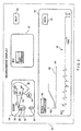
- FIG. 3 After interrogation by the programmer P, several graphic elements are displayed on screen 32 as shown in Figure 3.
- the screen 32 is partitioned into several sections.
- One section 34 is designated the Implant Environment Display (IED) for showing the implant and its connections of the heart of the patient.
- Another section 52 is designated the data base section and is used to access, and if necessary, modify data stored in the programmer P.
- a third section 54 is designated the Event Sequence Display (ESD).
- ESD Event Sequence Display
- HELP Event Sequence Display
- the IED is dedicated to show the implant and its relationship to the heart. More particularly, on Figure 3 it is indicated that the implant 38 is coupled to the heart 36 by an atrial lead 40 and a ventricular lead 42.
- the labels SP in the heart 36 adjacent to the ends of the leads 40, 42 indicate that each lead is being used for both Sensing and Pacing. These can be changed by activating and choosing from the Option Box (OB) discussed below.
- OB Option Box
- the section IED 34 also includes several 'hypertext' type labels as well. These labels include several characters surrounded by circles. One such label 44 disposed near the heart 36 bears the letters MV. Other such labels 46 and 48 with the letters 'ip' and 'il' respectively are associated with the implant 34.
- a cursor 50 can be moved across display 32 via the keyboard 14 or pointing device 20.
- a corresponding Option box appears showing a list of parameters or other information related to the selected hypertext window.
- an Option box appears on screen 32. This OB lists choices such as: MV-On/Off PIG- On/Off, ESD: On/Off, etc.
- an option box for "Implant Parameters” is displayed.
- the Option Box for "IP” will have choices such as: List Parameters: Yes/No; ESD: A/V/AV/ECG/Off, ESD: Full/Standard.
- the "List Parameters” is a convenience option allowing all the parameters to be programmed from the graphic displays.
- the ESD option specifies the graphic information to be presented on the display ESD section 54. When A or V is selected, atrial or ventricular activity is displayed, respectively. The AV choice yields a display showing both atrial and ventricular activity.
- the choice ECG yields an ECG presentation as shown in Figure 3 in the ESD 54, at 58. "Full” indicates that all refractory and blanking times are displayed. The "standard” choice does not show the refractory and blanking times.
- the data base section 52 includes a list of commands such as 'LIST' and 'SEARCH'. Selecting the 'LIST' command yields a list of information in the data base. This will be information on pulse generators, programming sequences, simulation sequences, etc. Selecting the 'SEARCH' command permits a user searching for a particular programmable parameter, simulation, pulse generator, etc. The selection of commands is also performed by using the pointing cursor 50 described above.
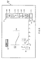
- Section 54 of the display 32 is the ESD section used to show the graphic information selected with the option boxes for the IP and MV labels discussed above. Details of this section are shown in Figure 6. Importantly, this section 54 is used to display two different types of graphs.
- the first type of graph 56 is a parameter inter-relational graph (PIG) i.e., a graph which shows the relationship between two operational parameters of the implant 38. This section is activated by the option box associated with the MV label. For example, the graph 56 may be showing the AV delay as a function of the ventricular pacing rate (VR).
- PAG parameter inter-relational graph
- the second graph 58 of ESD 54 shows the event sequence diagram selected with OB 51 associated with the IP label 46.
- the information for these two graphs 56, 58 is provided by the graphic elements 24 and 26 respectively based on data received from the microprocessor 40. In essence these are individual windows.
- the ESD 54 includes the two types of graphs, PIG 56 and ECG 58.
- the display includes various other indicia.
- the sensing threshold 57 disposed on the right side of display 58. This indicia is used to indicate the current sensing threshold of the patient's heart and is calibrated in millivolts. The threshold level may be repeated as a horizontal bar 57A adjacent to an R-wave.
- Another indicia is the current ventricular level 59 calibrated in volts.
- ESD 54 Also provided on ESD 54 is a menu bar 55.
- the menu bar 55 is displayed by a plurality of control icons 61. These icons when selected and dragged over the graph 58, allow the user to vary the characteristics of the graphs 56, 58 or the parameters displayed thereon. For example, the pacing pulse amplitude may be increased or decreased by pointing out a pacing pulse on the ECG, or if there is no pacing pulse, placing one with ICON 61F.
- the other indicia on display ESD 54 is the real/-simulation indicia 63. This indicia shows whether the graphs 54, 56 are based on real data from pacer of data from simulator.
- the EXPAND function selected in Fig. 6 by icon 61B is an important feature for both interrogation and diagnosis.
- the expanded screen fulfills the need for insight into what is happening in a specific location on the ESD or PIG graphs and also gives insight into the program used parameters.
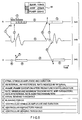
- graph 54 is expanded (in response to selecting the icon) to three time variant charts 54A, 54B, 54C.
- Chart 54B in this case is a surface ECG.
- the various artefacts on these charts are defined in the table at the bottom of the Figure.
- Pointing to a region on any charts presents the various controls parameters that occur in this region and are displayed by numerical displays such as display 83.
- pointing to a region such as the "R" wave would show periods 3 and 8, i.e., PVARP (extension if program used and "R" is a PVC), ventricular refractory periods, resetable refractory periods etc.
- the process is preferably a nested process, meaning that each display could allow access to further detail.
- the process also reveals an Option Box (OB) (not shown) which displays the actual values of parameters and provide the option of changing the parameters either for the implant or the simulation (shown at 85 in Fig. 5).
- OB Option Box
- the correlating indicia generator 26 generates graphic elements which provide an indicia for correlating the two graphs 56, 58 (this indicia has been omitted from Figures 3 and 6 for the sake of clarity.)
- graph 56' shows a classic representation of the ventricular pace rate (VPR) as a function of atrial sensed rate (ASR) as applied by the implant 38 using a Wenckebach technique.
- the graph 58' shows an ECG for the patient's heart while the pacing defined in graph 56' is applied.
- a plurality of indicia elements are provided. These indicia elements can be in the form of lines such as lines 60 connecting particular points on graph 56' to corresponding points on graph 58'. Alternatively, or in addition, certain points on graph 56' are identified by letters such as A, B, C, ...H.
- the corresponding points on graph 58' are identified by the same letters.
- the pacemaker has been operating in the mode identified by letter A on graph 56'.
- other types of graphic elements can be used as correlating indicia elements, such as color, (i.e., the corresponding portions of graphs 56', 58' can be represented by the same color), line type, (corresponding portions of graphs 56', 58' could be represented by the same type of line, i.e. thick, thin, dotted, etc.) and so on.
- the display portion 54 of the Figure with the two graphic elements 56, 58 and the correlation indicia 60 provides comprehensive representation of the operation of the heart 36 and the implant 38.
- Another feature of the present invention is that the user has the option of selecting new parameters and determining how the implant will function with these parameters without actually operating the implant with the selected parameters.
- a physician decided to change the pacemaker parameters, he had to enter these parameters into the pacemaker first, and then request the patient to go through various exercises to charge the hear and monitor the response of the pacemaker and the heart. This procedure was necessary so that the physician could determine if the pacemaker programming was satisfactory.
- step S106 Figure 2
- new parameters for the simulation are obtained from the user, via the keyboard 14, or down loaded from the patient's heart via the pacemaker in step S116.
- the user does not enter all the necessary operational parameters necessary for the pacemaker. Rather, the user provides certain preselected parameters such as age and sex of the patient, physical condition, upper and lower pacing rates, and so on. The remainder of the parameters are calculated by the cardiac simulation device 22 in step S118.
- the new set of parameters are provided to the graphic elements generators.
- the graphic elements are then generated in the same manner as the actual parameters in steps S110-S114 as discussed above. (Fig. 2).
- a box 62 is provided on the screen 32 to indicated whether the represented graphic elements are based on the actual or simulated data.
- step S120 a check is performed to determine if actual or simulated graphic elements are displayed. If the parameters are actual then the microprocessor returns to a standby mode and waits for further instructions. If the data is simulated, then in step S122 the user is requested to indicate whether the newly selected parameters are acceptable. If the parameters are acceptable, then in step S124 the selected parameters are sent or downloaded to the implant 38 and the operation of the programmer 10 is complete. If the parameters are unacceptable, then in step S126 new parameters are selected and the microprocessor 10 proceeds to step S109 (Fig. 2).
Abstract
Description
- This invention pertains to programmers used to initialize, monitor and modify the operation of implanted pacemakers or similar heart stimulation devices, and more particularly to a programmer having an improved graphic interface selected to provide a wide range of information to the physician.
- Programmers are used to initialize and service various implanted devices for cardiac therapy. These devices include pacemakers, cardioversion/defibrillator devices, and so on. Presently, typical programmers provided to the physician are generally the size and shape of a portable or laptop computer. Communication with an implanted device is accomplished through inductive coupling by using an accessory connected to the programmer, commonly called a "wand." The programmers further include a screen for displaying alphanumeric information, and, optionally, to display graphic information such, as for example, an ECG. The programmer may also include a printer for printing of various information, such as the programming parameters set for a particular pacemaker, data logged by the pacemaker for a preselected period, or an ECG.
- A disadvantage of the present programmers involves the techniques used to both collect and display information to the physician. The ECG is the only graphic information presented and it is essentially nothing more than a time-dependent graph of the QRST complex sensed in the heart. The remaining information is presented to the physician in the form of lists of parameters and associated parameter values.
- Similar table formats are used to provide other information as well. To change the programming, or initiate the programming for a newly implanted pacemaker, the physician must go through several pages of other tables and, in response to prompts, must select the various operational parameters. This whole process is time consuming and requires a steep and long learning curve for the physician. Moreover, because information is displayed by, or fed to the programmer in form of these tables, the physician lacks an intuitive feeling for these parameters and can interpret the same only after years of experience. Moreover, this problem is intensified as the complexity of implantable devices, and concurrently, the number of parameters increases.
- In view of the above-mentioned disadvantages of the prior art, it is an objective of the present invention to provide a programmer having a user interface which presents information in a clear, succinct manner such that a physician can at one glance, establish the status and the configuration of a device, with clear indications of its operational limits.
- A further objective is to provide a programmer that is flexible so that it can be used for a wide variety of implantable devices, such as pacemakers for both brady- and tachy-cardia, cardioversion/defibrillation devices, and so on.
- A further objective of the invention is to provide a programmer having a user friendly graphic interface which can be readily used without the need for consulting bulky manuals,and/or spending long hours in training.
- Another objective is to provide a programmer with means of displaying graphically a simulation of the heart and a cardiac therapy device as well as their present operation and simulated operation when the device's operational parameters are changed.
- A further objective is to provide a programmer which can reprogram or reconfigure the implanted device by manipulating the graphic symbols and presentations in such a manner that the graphic presentation will display the new programmed parameters to scale in intervals and amplitudes.
- A further objective is to supply a help function for a pacemaker programmer such that pointing at any object or a sequence will present to the user information about a corresponding event or parameter. Other objectives and advantages of the invention shall become apparent from the following description of the invention.
- Briefly, a programmer constructed in accordance with this invention includes a user interface consisting of a display and means for displaying on said display several graphic elements, including an element showing a time dependent parameter related to a cardiac function, such as an ECG, and another element showing a relationship between two cardiac function parameters. Importantly, the user interface further includes means for generating indicia on said display relating events from one graphic elements to events on the other graphic element.
- The programmer further includes simulating means for simulating the response of a patient's heart to certain functional parameters, and selection means for selectively displaying on said display graphic elements descriptive of either actual cardiac functions or simulated cardiac functions as determined by said simulating means.
- The simulator further has the facility of responding to the movement of icons by the user into an overlapping relationship with the timing sequences. These icons can represent either stimuli or natural heart beats such as "P-" "R-" waves.
-
- Figure 1 shows a block diagram of a programmer constructed in accordance with this invention;
- Figure 2 shows a block diagram descriptive of the operation of the programmer;
- Figure 3 shows a main screen of the display;
- Figure 4 shows how the two graphic elements and the correlation indicia are shown on the display of Figure 3;
- Figure 5 shows the "help" function which reveals, quantifies and explains various parameters; and
- Figure 6 shows the use of icons for simulation purposes.
- Referring now to Figure 1, a programmer P constructed in accordance with this invention includes a
microprocessor 10, a memory 12, akeyboard 14, and adisplay 16. An interface 18 provides communication through awand 30 with animplant 38. Theimplant 38 is coupled to a patient'sheart 36 byleads programmer 10 to establish communication with theimplant 38, collect information from theimplant 38, and generate operational parameters (and programming steps, if necessary) and send the same to theimplant 38. Additional information or selections by a physician are entered onkeyboard 14 and/or a pointing device, commonly referred to as a 'mouse', 20, or another similar pointing device which can be used to select information from the display. - In accordance with this invention, the programmer also includes a
cardiac simulator 22,graphic element generators correlation indicia generator 27. The programmer P contains other graphic element generators for generating graphic elements ondisplay 16, as discussed below but which have been omitted for the sake of simplicity. Thegraphic element generators cardiac simulator 22,keyboard 14,display 16,keyboard 14,pointing device 20, all cooperate with themicroprocessor 10 to form an easy to use user interface. - The operation of the programmer P is best described in conjunction with the flow chart of Figure 2. As previously mentioned, in order to initialize or service an implanted
device 38, the programmer P first establishes communication with the device through interface 18 and wand 30. This process is indicated in Figure 2 bystep 100. Once communication has been established (i.e., a handshaking protocol takes place), themicroprocessor 10 retrieves various information from theimplant 38. This information may be patient and/or device specific, i.e., it may describe the implantation date, the name and physical condition of the patient, as well as the serial and model number of theimplant 38. Importantly, the current operational parameters of theimplant 38 are also downloaded into programmer P. For initialization, these parameters may be set at default values. Finally, various information logged over a preselected time period, such as a current ECG, and a threshold impedance may also be stored by theimplant 38 and downloaded to theprogrammer 10, as indicated by step S104. - After interrogation by the programmer P, several graphic elements are displayed on
screen 32 as shown in Figure 3. Thescreen 32 is partitioned into several sections. Onesection 34 is designated the Implant Environment Display (IED) for showing the implant and its connections of the heart of the patient. Anothersection 52 is designated the data base section and is used to access, and if necessary, modify data stored in the programmer P. Athird section 54 is designated the Event Sequence Display (ESD). Finally, asection 53 is designated HELP and is provided to assist the user with various functions of the programmer P. - As mentioned before, the IED is dedicated to show the implant and its relationship to the heart. More particularly, on Figure 3 it is indicated that the
implant 38 is coupled to theheart 36 by anatrial lead 40 and aventricular lead 42. The labels SP in theheart 36 adjacent to the ends of theleads - The section IED 34 also includes several 'hypertext' type labels as well. These labels include several characters surrounded by circles. One
such label 44 disposed near theheart 36 bears the letters MV. Othersuch labels implant 34. - A
cursor 50 can be moved acrossdisplay 32 via thekeyboard 14 orpointing device 20. When labels of the IED are selected by the user with thecursor 50 or other means, a corresponding Option box appears showing a list of parameters or other information related to the selected hypertext window. For example, when thelabel 44 is selected, an Option box (OB) appears onscreen 32. This OB lists choices such as: MV-On/Off PIG- On/Off, ESD: On/Off, etc. When thelabel 46 is selected, an option box for "Implant Parameters" is displayed. The Option Box for "IP" will have choices such as: List Parameters: Yes/No; ESD: A/V/AV/ECG/Off, ESD: Full/Standard. The "List Parameters" is a convenience option allowing all the parameters to be programmed from the graphic displays. The ESD option specifies the graphic information to be presented on thedisplay ESD section 54. When A or V is selected, atrial or ventricular activity is displayed, respectively. The AV choice yields a display showing both atrial and ventricular activity. The choice ECG yields an ECG presentation as shown in Figure 3 in theESD 54, at 58. "Full" indicates that all refractory and blanking times are displayed. The "standard" choice does not show the refractory and blanking times. - Similarly choosing the label 'il' yields a display of the logged information. This information may be displayed on the modified ESD which will show events over a time period starting from the time last programming was done. The "DDDR" shown in the upper left hand corner indicates the mode of operation of
pacemaker 38. - The
data base section 52 includes a list of commands such as 'LIST' and 'SEARCH'. Selecting the 'LIST' command yields a list of information in the data base. This will be information on pulse generators, programming sequences, simulation sequences, etc. Selecting the 'SEARCH' command permits a user searching for a particular programmable parameter, simulation, pulse generator, etc. The selection of commands is also performed by using the pointingcursor 50 described above. -
Section 54 of thedisplay 32 is the ESD section used to show the graphic information selected with the option boxes for the IP and MV labels discussed above. Details of this section are shown in Figure 6. Importantly, thissection 54 is used to display two different types of graphs. The first type ofgraph 56 is a parameter inter-relational graph (PIG) i.e., a graph which shows the relationship between two operational parameters of theimplant 38. This section is activated by the option box associated with the MV label. For example, thegraph 56 may be showing the AV delay as a function of the ventricular pacing rate (VR). - The
second graph 58 ofESD 54 shows the event sequence diagram selected with OB 51 associated with theIP label 46. The information for these twographs graphic elements microprocessor 40. In essence these are individual windows. - Referring now to Figure 6, the
ESD 54 includes the two types of graphs,PIG 56 andECG 58. In addition, the display includes various other indicia. Once such indicia is thesensing threshold 57 disposed on the right side ofdisplay 58. This indicia is used to indicate the current sensing threshold of the patient's heart and is calibrated in millivolts. The threshold level may be repeated as ahorizontal bar 57A adjacent to an R-wave. Another indicia is thecurrent ventricular level 59 calibrated in volts. - Also provided on
ESD 54 is amenu bar 55. When selected, themenu bar 55 is displayed by a plurality ofcontrol icons 61. These icons when selected and dragged over thegraph 58, allow the user to vary the characteristics of thegraphs ICON 61F. - The other indicia on
display ESD 54 is the real/-simulation indicia 63. This indicia shows whether thegraphs - The EXPAND function selected in Fig. 6 by
icon 61B is an important feature for both interrogation and diagnosis. The expanded screen fulfills the need for insight into what is happening in a specific location on the ESD or PIG graphs and also gives insight into the program used parameters. - As shown in Fig. 5
graph 54 is expanded (in response to selecting the icon) to threetime variant charts Chart 54B in this case is a surface ECG. The various artefacts on these charts are defined in the table at the bottom of the Figure. Pointing to a region on any charts presents the various controls parameters that occur in this region and are displayed by numerical displays such asdisplay 83. As an example, pointing to a region such as the "R" wave would showperiods - If the ESD is in "simulation" mode, then various "Pace" and "Sense" events can be placed into the ESD display and the resultant timing cycles displayed.
- While it is very helpful to the user to have these two graphs shown simultaneously, the display alone may still be deficient in that it does not show a cause-and-effect relationship. In other words, merely by looking at these two graphs, the user does not get a sense of how certain points on one graph are related to points on the other graph. Therefore, an important feature of the invention is that the correlating
indicia generator 26 generates graphic elements which provide an indicia for correlating the twographs 56, 58 (this indicia has been omitted from Figures 3 and 6 for the sake of clarity.) - An example illustrating this correlation indicia feature is shown in Figure 4. In this Figure, graph 56' shows a classic representation of the ventricular pace rate (VPR) as a function of atrial sensed rate (ASR) as applied by the
implant 38 using a Wenckebach technique. The graph 58' shows an ECG for the patient's heart while the pacing defined in graph 56' is applied. In order to show the correlation between these two graphs 56', 58', a plurality of indicia elements are provided. These indicia elements can be in the form of lines such aslines 60 connecting particular points on graph 56' to corresponding points on graph 58'. Alternatively, or in addition, certain points on graph 56' are identified by letters such as A, B, C, ...H. The corresponding points on graph 58' are identified by the same letters. Thus when the QRST complex identified by letter A on graph 58' is sensed by the pacemaker, the pacemaker has been operating in the mode identified by letter A on graph 56'. Of course other types of graphic elements can be used as correlating indicia elements, such as color, (i.e., the corresponding portions of graphs 56', 58' can be represented by the same color), line type, (corresponding portions of graphs 56', 58' could be represented by the same type of line, i.e. thick, thin, dotted, etc.) and so on. - In this manner, the
display portion 54 of the Figure with the twographic elements correlation indicia 60 provides comprehensive representation of the operation of theheart 36 and theimplant 38. - Another feature of the present invention is that the user has the option of selecting new parameters and determining how the implant will function with these parameters without actually operating the implant with the selected parameters. Prior to this invention, if a physician decided to change the pacemaker parameters, he had to enter these parameters into the pacemaker first, and then request the patient to go through various exercises to charge the hear and monitor the response of the pacemaker and the heart. This procedure was necessary so that the physician could determine if the pacemaker programming was satisfactory.
- Of course, this prior approach was time consuming and uncomfortable for the patient, especially if it had to be repeated several times for different operational parameters. In the present invention, the user is given the opportunity to enter a new set of parameters and to have the programmer simulate the operation of the pacemaker and the heart in accordance with these parameters. This may be accomplished as discussed above by asking in step S106 (Figure 2) whether a simulation is desired or not. If a simulation is requested, then new parameters for the simulation are obtained from the user, via the
keyboard 14, or down loaded from the patient's heart via the pacemaker in step S116. Of course, as well known in the art, the user does not enter all the necessary operational parameters necessary for the pacemaker. Rather, the user provides certain preselected parameters such as age and sex of the patient, physical condition, upper and lower pacing rates, and so on. The remainder of the parameters are calculated by thecardiac simulation device 22 in step S118. - The new set of parameters are provided to the graphic elements generators. The graphic elements are then generated in the same manner as the actual parameters in steps S110-S114 as discussed above. (Fig. 2). A
box 62 is provided on thescreen 32 to indicated whether the represented graphic elements are based on the actual or simulated data. - After the graphic elements are displayed as shown in Figure 3, in step S120 a check is performed to determine if actual or simulated graphic elements are displayed. If the parameters are actual then the microprocessor returns to a standby mode and waits for further instructions. If the data is simulated, then in step S122 the user is requested to indicate whether the newly selected parameters are acceptable. If the parameters are acceptable, then in step S124 the selected parameters are sent or downloaded to the
implant 38 and the operation of theprogrammer 10 is complete. If the parameters are unacceptable, then in step S126 new parameters are selected and themicroprocessor 10 proceeds to step S109 (Fig. 2). - Although the invention has been described with reference to several particular embodiments, it is to be understood that these embodiments are merely illustrative of the application of the principles of the invention. Accordingly, the embodiments described in particular should be considered exemplary, not limiting, with respect to the following claims.
Claims (14)
- A graphic display apparatus for displaying information on a screen related to the operation of a cardiac implant and associated cardiac functions, said apparatus comprising:first generating means for generating a first graphic image descriptive of a first cardiac parameter from said information;second generating means for displaying a second graphic image descriptive of a dependency between said first and a second parameter; andindicia generating means for generating indicia interrelating said first and second images.
- Apparatus according to claim 1 further comprising display means for displaying said first and second images and said indicia on said screen.
- Apparatus according to claim 1 or 2 wherein said first and second parameters are one of actual and simulated parameters.
- Apparatus according to claim 1 or 2 wherein said first and second parameters are actual parameters derived from information obtained from one of said patient and said cardiac device.
- Apparatus according to claim 1 or 2 further comprising simulation means for selecting a set of simulated parameters, said first and second parameters being selected from said set of simulated parameters.
- Apparatus according to claim 5 further comprising third generating means for generating a third image representative of said simulated parameters and selection means for selecting said first and second parameters from said image.
- Apparatus according to claim 6 wherein said selection means includes image moving means for moving said images in a superimposing relationship.
- A graphic user interface for a cardiac implant, said implant being constructed and arranged for implantation in a patient, said interface comprising:means for receiving data including information descriptive of an operation of said patient's heart and information descriptive of an operation of said implant;means for generating a first and a second image corresponding to a first parameter and a second parameter characterized by said data;means for generating an indicia descriptive of a relationship between said first and second parameter; andmeans for superimposing said indicia on said images.
- An interface according to claim 8 wherein said first parameter is a rate responsive parameter and said second parameter is an ECG obtained from said patient.
- An interface according to claim 8 wherein said first image is illustrative of an ECG and said second image is a time-dependent graph of various cardiac events.
- An interface according to claim 8 further comprising simulating means for generating simulated parameters, one of said first and second parameters being selected from said simulated parameters.
- An interface according to claim 8 further comprising means for generating a graphic cardiac image related to said heart, means for generating selection points on said graphic cardiac means and means for pointing to one of said selection points.
- An interface according to claim 12 further comprising data display means for displaying selected data responsive to one of said selection points.
- An interface according to claim 8 further comprising programming means for generating programming parameters for said implant based on said images.
Applications Claiming Priority (2)
| Application Number | Priority Date | Filing Date | Title |
|---|---|---|---|
| US08/554,483 US5713937A (en) | 1995-11-07 | 1995-11-07 | Pacemaker programmer menu with selectable real or simulated implant data graphics |
| US554483 | 1995-11-07 |
Publications (3)
| Publication Number | Publication Date |
|---|---|
| EP0773038A2 true EP0773038A2 (en) | 1997-05-14 |
| EP0773038A3 EP0773038A3 (en) | 1998-09-23 |
| EP0773038B1 EP0773038B1 (en) | 2004-02-25 |
Family
ID=24213522
Family Applications (1)
| Application Number | Title | Priority Date | Filing Date |
|---|---|---|---|
| EP96307877A Expired - Lifetime EP0773038B1 (en) | 1995-11-07 | 1996-10-30 | Improved graphic interface for pacemaker programmers |
Country Status (3)
| Country | Link |
|---|---|
| US (1) | US5713937A (en) |
| EP (1) | EP0773038B1 (en) |
| DE (1) | DE69631633T2 (en) |
Cited By (12)
| Publication number | Priority date | Publication date | Assignee | Title |
|---|---|---|---|---|
| WO1998010835A1 (en) * | 1996-09-16 | 1998-03-19 | Sulzer Intermedics Inc. | Method and apparatus for dual chamber cardiac analysis |
| WO2001043822A1 (en) * | 1999-12-16 | 2001-06-21 | St. Jude Medical Ab | Programming system for medical devices |
| WO2001043821A1 (en) * | 1999-12-16 | 2001-06-21 | St. Jude Medical Ab | Programming system for medical devices |
| WO2002007815A1 (en) * | 2000-07-21 | 2002-01-31 | St. Jude Medical Ab | A system for monitoring an implantable medical device using graphical representation |
| US6356789B1 (en) | 1997-11-07 | 2002-03-12 | Medtronic Inc. | Medical information device |
| WO2007027537A1 (en) * | 2005-08-31 | 2007-03-08 | Medtronic, Inc. | Apparatus and method for testing an implantable medical device and sensing parameter settings |
| EP1925337A1 (en) | 2006-11-27 | 2008-05-28 | BIOTRONIK CRM Patent AG | Heart stimulator |
| WO2008091268A1 (en) * | 2007-01-26 | 2008-07-31 | Medtronic, Inc. | Graphical configuration of electrodes for electrical stimulation |
| US8346361B2 (en) | 2003-10-02 | 2013-01-01 | Medtronic, Inc. | User interface for external charger for implantable medical device |
| US9259584B2 (en) | 2003-10-02 | 2016-02-16 | Medtronic, Inc. | External unit for implantable medical device coupled by cord |
| US10335588B2 (en) | 2006-02-24 | 2019-07-02 | Medtronic, Inc. | Unwrapped 2D view of a stimulation lead with complex electrode array geometry |
| US10441801B2 (en) | 2002-11-15 | 2019-10-15 | Medtronic, Inc. | Human-implantable-neurostimulator user interface having multiple levels of abstraction |
Families Citing this family (91)
| Publication number | Priority date | Publication date | Assignee | Title |
|---|---|---|---|---|
| US5833623A (en) * | 1996-05-14 | 1998-11-10 | Pacesetter, Inc. | System and method for facilitating rapid retrieval and evaluation of diagnostic data stored by an implantable medical device |
| US6609031B1 (en) * | 1996-06-07 | 2003-08-19 | Advanced Neuromodulation Systems, Inc. | Multiprogrammable tissue stimulator and method |
| US5891179A (en) * | 1997-11-20 | 1999-04-06 | Paceseter, Inc. | Method and apparatus for monitoring and displaying lead impedance in real-time for an implantable medical device |
| DE19809814B4 (en) * | 1998-03-09 | 2007-06-06 | Aviteq Vibrationstechnik Gmbh | Method and device for operating a vibration system |
| US6266555B1 (en) | 1998-05-07 | 2001-07-24 | Medtronic, Inc. | Single complex electrogram display having a sensing threshold for an implantable medical device |
| US6161039A (en) * | 1998-05-07 | 2000-12-12 | Medtronic, Inc. | Trigger enhanced electrogram display for positioning an implantable medical device |
| US6493579B1 (en) | 1999-08-20 | 2002-12-10 | Cardiac Pacemakers, Inc. | System and method for detection enhancement programming |
| US6289248B1 (en) * | 1999-08-20 | 2001-09-11 | Cardiac Pacemakers, Inc. | System and method for detecting and displaying parameter interactions |
| US6381496B1 (en) * | 1999-10-01 | 2002-04-30 | Advanced Bionics Corporation | Parameter context switching for an implanted device |
| US6600949B1 (en) | 1999-11-10 | 2003-07-29 | Pacesetter, Inc. | Method for monitoring heart failure via respiratory patterns |
| US7050857B2 (en) * | 1999-12-16 | 2006-05-23 | St. Jude Medical Ab | Programming system for medical devices |
| US6473638B2 (en) * | 1999-12-24 | 2002-10-29 | Medtronic, Inc. | Medical device GUI for cardiac electrophysiology display and data communication |
| US20020026223A1 (en) * | 1999-12-24 | 2002-02-28 | Riff Kenneth M. | Method and a system for using implanted medical device data for accessing therapies |
| US6589188B1 (en) | 2000-05-05 | 2003-07-08 | Pacesetter, Inc. | Method for monitoring heart failure via respiratory patterns |
| US6454719B1 (en) | 2000-08-01 | 2002-09-24 | Pacesetter, Inc. | Apparatus and method for diagnosis of cardiac disease using a respiration monitor |
| US6622040B2 (en) * | 2000-12-15 | 2003-09-16 | Cardiac Pacemakers, Inc. | Automatic selection of stimulation chamber for ventricular resynchronization therapy |
| US7236826B2 (en) * | 2000-12-15 | 2007-06-26 | Cardiac Pacemakers, Inc. | System and method for graphically configuring leads |
| US7181285B2 (en) | 2000-12-26 | 2007-02-20 | Cardiac Pacemakers, Inc. | Expert system and method |
| US7526112B2 (en) * | 2001-04-30 | 2009-04-28 | Chase Medical, L.P. | System and method for facilitating cardiac intervention |
| US6675044B2 (en) * | 2001-05-07 | 2004-01-06 | Medtronic, Inc. | Software-based record management system with access to time-line ordered clinical data acquired by an implanted device |
| US6704598B2 (en) | 2001-05-23 | 2004-03-09 | Cardiac Pacemakers, Inc. | Cardiac rhythm management system selecting between multiple same-chamber electrodes for delivering cardiac therapy |
| US6704600B2 (en) | 2001-07-13 | 2004-03-09 | Cardiac Pacemakers, Inc. | Device programmer with enclosed imaging capability |
| US7286877B2 (en) * | 2001-07-13 | 2007-10-23 | Cardiac Pacemakers, Inc. | Device programmer with enclosed imaging capability |
| US7085604B2 (en) * | 2001-12-28 | 2006-08-01 | Medtronic, Inc. | Mechanical metaphor for representing parameter constraints graphically for medical devices |
| US7218968B2 (en) * | 2002-10-31 | 2007-05-15 | Medtronic, Inc. | User interface for programming rate response technical field |
| US7191006B2 (en) * | 2002-12-05 | 2007-03-13 | Cardiac Pacemakers, Inc. | Cardiac rhythm management systems and methods for rule-illustrative parameter entry |
| JP4385245B2 (en) * | 2002-12-06 | 2009-12-16 | 日本光電工業株式会社 | Defibrillator |
| CA2508800A1 (en) * | 2002-12-11 | 2004-06-24 | Proteus Biomedical, Inc. | Method and system for monitoring and treating hemodynamic parameters |
| US7065409B2 (en) * | 2002-12-13 | 2006-06-20 | Cardiac Pacemakers, Inc. | Device communications of an implantable medical device and an external system |
| US7009511B2 (en) | 2002-12-17 | 2006-03-07 | Cardiac Pacemakers, Inc. | Repeater device for communications with an implantable medical device |
| US7127300B2 (en) * | 2002-12-23 | 2006-10-24 | Cardiac Pacemakers, Inc. | Method and apparatus for enabling data communication between an implantable medical device and a patient management system |
| US7395117B2 (en) * | 2002-12-23 | 2008-07-01 | Cardiac Pacemakers, Inc. | Implantable medical device having long-term wireless capabilities |
| US20040128161A1 (en) * | 2002-12-27 | 2004-07-01 | Mazar Scott T. | System and method for ad hoc communications with an implantable medical device |
| US6978182B2 (en) * | 2002-12-27 | 2005-12-20 | Cardiac Pacemakers, Inc. | Advanced patient management system including interrogator/transceiver unit |
| US7136707B2 (en) | 2003-01-21 | 2006-11-14 | Cardiac Pacemakers, Inc. | Recordable macros for pacemaker follow-up |
| US7204798B2 (en) * | 2003-01-24 | 2007-04-17 | Proteus Biomedical, Inc. | Methods and systems for measuring cardiac parameters |
| US7272444B2 (en) * | 2003-05-07 | 2007-09-18 | Cardiac Pacemakers, Inc. | Medical device interface system with automatic rate threshold adjustment |
| US7289761B2 (en) | 2003-06-23 | 2007-10-30 | Cardiac Pacemakers, Inc. | Systems, devices, and methods for selectively preventing data transfer from a medical device |
| US20060041223A1 (en) * | 2004-08-18 | 2006-02-23 | Medtronic, Inc. | All-in-one interface for programmable implantable medical device |
| EP1799101A4 (en) * | 2004-09-02 | 2008-11-19 | Proteus Biomedical Inc | Methods and apparatus for tissue activation and monitoring |
| WO2006105474A2 (en) * | 2005-03-31 | 2006-10-05 | Proteus Biomedical, Inc. | Automated optimization of multi-electrode pacing for cardiac resynchronization |
| US20060089856A1 (en) * | 2004-10-21 | 2006-04-27 | Cardiac Pacemakers | Integrated pharmaceutical dispensing and patient management monitoring |
| US8150509B2 (en) * | 2004-10-21 | 2012-04-03 | Cardiac Pacemakers, Inc. | Systems and methods for drug therapy enhancement using expected pharmacodynamic models |
| EP1898999A4 (en) * | 2005-07-01 | 2011-10-19 | Proteus Biomedical Inc | Deployable epicardial electrode and sensor array |
| US7752059B2 (en) * | 2005-07-05 | 2010-07-06 | Cardiac Pacemakers, Inc. | Optimization of timing for data collection and analysis in advanced patient management system |
| US7706867B1 (en) | 2005-08-04 | 2010-04-27 | Pacesetter, Inc. | Methods and systems to correlate arrhythmic and ischemic events |
| WO2007021804A2 (en) * | 2005-08-12 | 2007-02-22 | Proteus Biomedical, Inc. | Evaluation of depolarization wave conduction velocity |
| US20100204766A1 (en) * | 2005-12-22 | 2010-08-12 | Mark Zdeblick | Implantable integrated circuit |
| US8612024B2 (en) | 2006-02-24 | 2013-12-17 | Medtronic, Inc. | User interface with 3D environment for configuring stimulation therapy |
| US7613672B2 (en) | 2006-04-27 | 2009-11-03 | Cardiac Pacemakers, Inc. | Medical device user interface automatically resolving interaction between programmable parameters |
| US8644930B2 (en) | 2006-08-28 | 2014-02-04 | Medtronic, Inc. | Operational electrode impedance measurement for an implantable medical stimulator |
| US20080103552A1 (en) * | 2006-10-31 | 2008-05-01 | Medtronic, Inc. | Controller for obtaining prescriptive analysis of functionality of implantable medical device leads, system and method therefore |
| WO2008070142A2 (en) | 2006-12-06 | 2008-06-12 | Medtronic, Inc. | User interface with toolbar for programming electrical stimulation therapy |
| US8121689B2 (en) | 2007-10-01 | 2012-02-21 | Cardiac Pacemakers, Inc. | Proactive interactive limits override for implantable medical device user interface |
| US8473069B2 (en) * | 2008-02-28 | 2013-06-25 | Proteus Digital Health, Inc. | Integrated circuit implementation and fault control system, device, and method |
| US8195294B2 (en) * | 2008-04-30 | 2012-06-05 | Medtronic, Inc. | Multi-stage testing of electrodes of implantable medical device, system and method |
| US9238135B2 (en) * | 2008-04-30 | 2016-01-19 | Medtronic, Inc. | Flagging of electrodes of an implantable medical device, controller, system and method therefore |
| US8838242B2 (en) * | 2008-04-30 | 2014-09-16 | Medtronic, Inc. | Pre-configuration of electrode measurement of an implantable medical device, system and method therefore |
| US9849294B2 (en) * | 2008-08-11 | 2017-12-26 | Cardiac Pacemakers, Inc. | Systems and methods for controlling rate responsive pacing |
| WO2010065465A2 (en) * | 2008-12-02 | 2010-06-10 | Proteus Biomedical, Inc. | Analyzer compatible communication protocol |
| US20110082530A1 (en) * | 2009-04-02 | 2011-04-07 | Mark Zdeblick | Method and Apparatus for Implantable Lead |
| DE202010018338U1 (en) * | 2009-04-22 | 2015-10-12 | Nevro Corporation | Spinal cord modulation system for the relief of chronic pain |
| JP2012525206A (en) * | 2009-04-29 | 2012-10-22 | プロテウス バイオメディカル インコーポレイテッド | Method and apparatus for leads for implantable devices |
| US20110022981A1 (en) * | 2009-07-23 | 2011-01-27 | Deepa Mahajan | Presentation of device utilization and outcome from a patient management system |
| WO2011011736A2 (en) | 2009-07-23 | 2011-01-27 | Proteus Biomedical, Inc. | Solid-state thin film capacitor |
| US8364272B2 (en) * | 2010-04-30 | 2013-01-29 | Medtronic, Inc. | Brain stimulation programming |
| US8600504B2 (en) | 2010-07-02 | 2013-12-03 | Cardiac Pacemakers, Inc. | Physiologic demand driven pacing |
| WO2012019036A1 (en) * | 2010-08-06 | 2012-02-09 | Cardiac Pacemakers, Inc. | User interface system for use with multipolar pacing leads |
| US8355784B2 (en) | 2011-05-13 | 2013-01-15 | Medtronic, Inc. | Dynamic representation of multipolar leads in a programmer interface |
| US9180302B2 (en) | 2012-08-31 | 2015-11-10 | Greatbatch Ltd. | Touch screen finger position indicator for a spinal cord stimulation programming device |
| US8812125B2 (en) | 2012-08-31 | 2014-08-19 | Greatbatch Ltd. | Systems and methods for the identification and association of medical devices |
| US9594877B2 (en) | 2012-08-31 | 2017-03-14 | Nuvectra Corporation | Virtual reality representation of medical devices |
| US9259577B2 (en) | 2012-08-31 | 2016-02-16 | Greatbatch Ltd. | Method and system of quick neurostimulation electrode configuration and positioning |
| US9507912B2 (en) | 2012-08-31 | 2016-11-29 | Nuvectra Corporation | Method and system of simulating a pulse generator on a clinician programmer |
| US8903496B2 (en) | 2012-08-31 | 2014-12-02 | Greatbatch Ltd. | Clinician programming system and method |
| US9375582B2 (en) | 2012-08-31 | 2016-06-28 | Nuvectra Corporation | Touch screen safety controls for clinician programmer |
| US9615788B2 (en) | 2012-08-31 | 2017-04-11 | Nuvectra Corporation | Method and system of producing 2D representations of 3D pain and stimulation maps and implant models on a clinician programmer |
| US8983616B2 (en) | 2012-09-05 | 2015-03-17 | Greatbatch Ltd. | Method and system for associating patient records with pulse generators |
| US8868199B2 (en) | 2012-08-31 | 2014-10-21 | Greatbatch Ltd. | System and method of compressing medical maps for pulse generator or database storage |
| US10668276B2 (en) | 2012-08-31 | 2020-06-02 | Cirtec Medical Corp. | Method and system of bracketing stimulation parameters on clinician programmers |
| US9471753B2 (en) | 2012-08-31 | 2016-10-18 | Nuvectra Corporation | Programming and virtual reality representation of stimulation parameter Groups |
| US8761897B2 (en) | 2012-08-31 | 2014-06-24 | Greatbatch Ltd. | Method and system of graphical representation of lead connector block and implantable pulse generators on a clinician programmer |
| US9767255B2 (en) | 2012-09-05 | 2017-09-19 | Nuvectra Corporation | Predefined input for clinician programmer data entry |
| US8757485B2 (en) | 2012-09-05 | 2014-06-24 | Greatbatch Ltd. | System and method for using clinician programmer and clinician programming data for inventory and manufacturing prediction and control |
| US9867991B2 (en) | 2013-07-31 | 2018-01-16 | Nevro Corp. | Physician programmer with enhanced graphical user interface, and associated systems and methods |
| US9468385B2 (en) | 2014-08-22 | 2016-10-18 | Medtronic, Inc. | Visual representation of a cardiac signal sensing test |
| CN106687173A (en) | 2014-09-15 | 2017-05-17 | 波士顿科学神经调制公司 | Graphical user interface for programming neurostimulation pulse patterns |
| AU2015343483B2 (en) | 2014-11-04 | 2018-03-01 | Boston Scientific Neuromodulation Corporation | Method and apparatus for programming complex neurostimulation patterns |
| US9984209B2 (en) | 2015-02-13 | 2018-05-29 | Medtronic, Inc. | Graphical controls for programming medical device operation |
| AU2016297965B2 (en) | 2015-07-30 | 2019-04-04 | Boston Scientific Neuromodulation Corporation | User interface for custom patterned electrical stimulation |
| WO2017066187A1 (en) | 2015-10-15 | 2017-04-20 | Boston Scientific Neuromodulation Corporation | User interface for neurostimulation waveform composition |
Family Cites Families (11)
| Publication number | Priority date | Publication date | Assignee | Title |
|---|---|---|---|---|
| DE3478739D1 (en) * | 1983-02-11 | 1989-07-27 | Vitatron Medical Bv | Biomedical system with improved marker channel means and method |
| US4791936A (en) * | 1985-02-15 | 1988-12-20 | Siemens-Pacesetter, Inc. | Apparatus for interpreting and displaying cardiac events of a heart connected to a cardiac pacing means |
| US4825869A (en) * | 1987-09-28 | 1989-05-02 | Telectronics N.V. | System for automatically performing a clinical assessment of an implanted pacer based on information that is telemetrically received |
| US4809697A (en) * | 1987-10-14 | 1989-03-07 | Siemens-Pacesetter, Inc. | Interactive programming and diagnostic system for use with implantable pacemaker |
| US4979506A (en) * | 1989-08-08 | 1990-12-25 | Siemens-Pacesetter, Inc. | Self-test system and method for external programming device |
| US5224486A (en) * | 1992-02-28 | 1993-07-06 | Hewlett-Packard Company | Method and apparatus for classifying heartbeat waveforms |
| US5431691A (en) * | 1992-03-02 | 1995-07-11 | Siemens Pacesetter, Inc. | Method and system for recording and displaying a sequential series of pacing events |
| US5372607A (en) * | 1993-06-23 | 1994-12-13 | Medtronic, Inc. | Method and apparatus for monitoring pacemaker intervals |
| US5421830A (en) * | 1993-08-27 | 1995-06-06 | Pacesetter, Inc. | Programming system having means for recording and analyzing a patient's cardiac signal |
| US5447164A (en) * | 1993-11-08 | 1995-09-05 | Hewlett-Packard Company | Interactive medical information display system and method for displaying user-definable patient events |
| US5413594A (en) * | 1993-12-09 | 1995-05-09 | Ventritex, Inc. | Method and apparatus for interrogating an implanted cardiac device |
-
1995
- 1995-11-07 US US08/554,483 patent/US5713937A/en not_active Expired - Lifetime
-
1996
- 1996-10-30 EP EP96307877A patent/EP0773038B1/en not_active Expired - Lifetime
- 1996-10-30 DE DE69631633T patent/DE69631633T2/en not_active Expired - Lifetime
Non-Patent Citations (1)
| Title |
|---|
| None |
Cited By (16)
| Publication number | Priority date | Publication date | Assignee | Title |
|---|---|---|---|---|
| WO1998010835A1 (en) * | 1996-09-16 | 1998-03-19 | Sulzer Intermedics Inc. | Method and apparatus for dual chamber cardiac analysis |
| US6356789B1 (en) | 1997-11-07 | 2002-03-12 | Medtronic Inc. | Medical information device |
| WO2001043822A1 (en) * | 1999-12-16 | 2001-06-21 | St. Jude Medical Ab | Programming system for medical devices |
| WO2001043821A1 (en) * | 1999-12-16 | 2001-06-21 | St. Jude Medical Ab | Programming system for medical devices |
| WO2002007815A1 (en) * | 2000-07-21 | 2002-01-31 | St. Jude Medical Ab | A system for monitoring an implantable medical device using graphical representation |
| US10441801B2 (en) | 2002-11-15 | 2019-10-15 | Medtronic, Inc. | Human-implantable-neurostimulator user interface having multiple levels of abstraction |
| US8346361B2 (en) | 2003-10-02 | 2013-01-01 | Medtronic, Inc. | User interface for external charger for implantable medical device |
| US11439836B2 (en) | 2003-10-02 | 2022-09-13 | Medtronic, Inc. | External energy transfer system for an implantable medical device and method therefor |
| US9259584B2 (en) | 2003-10-02 | 2016-02-16 | Medtronic, Inc. | External unit for implantable medical device coupled by cord |
| WO2007027537A1 (en) * | 2005-08-31 | 2007-03-08 | Medtronic, Inc. | Apparatus and method for testing an implantable medical device and sensing parameter settings |
| US10335588B2 (en) | 2006-02-24 | 2019-07-02 | Medtronic, Inc. | Unwrapped 2D view of a stimulation lead with complex electrode array geometry |
| US10342970B2 (en) | 2006-02-24 | 2019-07-09 | Medtronic, Inc. | Unwrapped 2D view of a stimulation lead with complex electrode array geometry |
| EP1925337A1 (en) | 2006-11-27 | 2008-05-28 | BIOTRONIK CRM Patent AG | Heart stimulator |
| US8233977B2 (en) | 2007-01-26 | 2012-07-31 | Medtronic, Inc. | Graphical configuration of electrodes for electrical stimulation |
| US8082034B2 (en) | 2007-01-26 | 2011-12-20 | Medtronic, Inc. | Graphical configuration of electrodes for electrical stimulation |
| WO2008091268A1 (en) * | 2007-01-26 | 2008-07-31 | Medtronic, Inc. | Graphical configuration of electrodes for electrical stimulation |
Also Published As
| Publication number | Publication date |
|---|---|
| EP0773038A3 (en) | 1998-09-23 |
| DE69631633D1 (en) | 2004-04-01 |
| EP0773038B1 (en) | 2004-02-25 |
| DE69631633T2 (en) | 2004-09-23 |
| US5713937A (en) | 1998-02-03 |
Similar Documents
| Publication | Publication Date | Title |
|---|---|---|
| US5713937A (en) | Pacemaker programmer menu with selectable real or simulated implant data graphics | |
| US7003349B1 (en) | Programming system for medical devices | |
| US5716384A (en) | Method and system for organizing, viewing and manipulating information in implantable device programmer | |
| US7783364B2 (en) | System and method for graphically configuring leads | |
| US7050857B2 (en) | Programming system for medical devices | |
| US5697959A (en) | Method and system for analyzing and displaying complex pacing event records | |
| US6842644B2 (en) | User navigation and guidance during configuration and storage of parameters for medical device | |
| US6577896B2 (en) | Single complex electrogram display having a sensing threshold for an implantable medical device | |
| US20170120056A1 (en) | Implantable pulse generator having current steering means | |
| US6393325B1 (en) | Directional programming for implantable electrode arrays | |
| EP0756877A2 (en) | Decision support system and method for an implantable cardiac stimulating device | |
| US8255053B2 (en) | Method and apparatus for question-based programming of cardiac rhythm management devices | |
| US6266566B1 (en) | Waveform normalization in a medical device | |
| WO2001048677A2 (en) | Medical device gui for cardiac electrophysiology display and data communication | |
| WO2001014008A1 (en) | Arrhythmia display | |
| US7020515B2 (en) | Presentation of data stored in an active implantable medical device to assist a practitioner's diagnosis | |
| US6161039A (en) | Trigger enhanced electrogram display for positioning an implantable medical device | |
| US7333856B1 (en) | Method and system to graphically display programming parameters for multi-chamber devices | |
| US6842643B1 (en) | Method and apparatus for resetting programming parameters within an implantable medical device | |
| BILLETTE et al. | A microcomputer‐based stimulator for clinical and experimental investigations in cardiac electrophysiology | |
| EP1242147B1 (en) | Programming system for medical devices | |
| WO2002007815A1 (en) | A system for monitoring an implantable medical device using graphical representation |
Legal Events
| Date | Code | Title | Description |
|---|---|---|---|
| PUAI | Public reference made under article 153(3) epc to a published international application that has entered the european phase |
Free format text: ORIGINAL CODE: 0009012 |
|
| AK | Designated contracting states |
Kind code of ref document: A2 Designated state(s): DE FR GB |
|
| PUAL | Search report despatched |
Free format text: ORIGINAL CODE: 0009013 |
|
| AK | Designated contracting states |
Kind code of ref document: A3 Designated state(s): DE FR GB |
|
| 17P | Request for examination filed |
Effective date: 19981113 |
|
| 17Q | First examination report despatched |
Effective date: 20020318 |
|
| RAP1 | Party data changed (applicant data changed or rights of an application transferred) |
Owner name: PACESETTER, INC. |
|
| GRAP | Despatch of communication of intention to grant a patent |
Free format text: ORIGINAL CODE: EPIDOSNIGR1 |
|
| GRAP | Despatch of communication of intention to grant a patent |
Free format text: ORIGINAL CODE: EPIDOSNIGR1 |
|
| GRAS | Grant fee paid |
Free format text: ORIGINAL CODE: EPIDOSNIGR3 |
|
| GRAA | (expected) grant |
Free format text: ORIGINAL CODE: 0009210 |
|
| AK | Designated contracting states |
Kind code of ref document: B1 Designated state(s): DE FR GB |
|
| REG | Reference to a national code |
Ref country code: GB Ref legal event code: FG4D |
|
| REF | Corresponds to: |
Ref document number: 69631633 Country of ref document: DE Date of ref document: 20040401 Kind code of ref document: P |
|
| ET | Fr: translation filed | ||
| PG25 | Lapsed in a contracting state [announced via postgrant information from national office to epo] |
Ref country code: GB Free format text: LAPSE BECAUSE OF NON-PAYMENT OF DUE FEES Effective date: 20041030 |
|
| PLBE | No opposition filed within time limit |
Free format text: ORIGINAL CODE: 0009261 |
|
| STAA | Information on the status of an ep patent application or granted ep patent |
Free format text: STATUS: NO OPPOSITION FILED WITHIN TIME LIMIT |
|
| 26N | No opposition filed |
Effective date: 20041126 |
|
| GBPC | Gb: european patent ceased through non-payment of renewal fee |
Effective date: 20041030 |
|
| PGFP | Annual fee paid to national office [announced via postgrant information from national office to epo] |
Ref country code: FR Payment date: 20051017 Year of fee payment: 10 |
|
| REG | Reference to a national code |
Ref country code: FR Ref legal event code: ST Effective date: 20070629 |
|
| PG25 | Lapsed in a contracting state [announced via postgrant information from national office to epo] |
Ref country code: FR Free format text: LAPSE BECAUSE OF NON-PAYMENT OF DUE FEES Effective date: 20061031 |
|
| PGFP | Annual fee paid to national office [announced via postgrant information from national office to epo] |
Ref country code: DE Payment date: 20131029 Year of fee payment: 18 |
|
| REG | Reference to a national code |
Ref country code: DE Ref legal event code: R119 Ref document number: 69631633 Country of ref document: DE |
|
| PG25 | Lapsed in a contracting state [announced via postgrant information from national office to epo] |
Ref country code: DE Free format text: LAPSE BECAUSE OF NON-PAYMENT OF DUE FEES Effective date: 20150501 |