EP0773003A1 - Electrosurgical electrode connector - Google Patents
Electrosurgical electrode connector Download PDFInfo
- Publication number
- EP0773003A1 EP0773003A1 EP96116167A EP96116167A EP0773003A1 EP 0773003 A1 EP0773003 A1 EP 0773003A1 EP 96116167 A EP96116167 A EP 96116167A EP 96116167 A EP96116167 A EP 96116167A EP 0773003 A1 EP0773003 A1 EP 0773003A1
- Authority
- EP
- European Patent Office
- Prior art keywords
- shaft
- pin
- exterior surface
- pins
- extending
- Prior art date
- Legal status (The legal status is an assumption and is not a legal conclusion. Google has not performed a legal analysis and makes no representation as to the accuracy of the status listed.)
- Withdrawn
Links
Images

Classifications
-
- A—HUMAN NECESSITIES
- A61—MEDICAL OR VETERINARY SCIENCE; HYGIENE
- A61B—DIAGNOSIS; SURGERY; IDENTIFICATION
- A61B18/00—Surgical instruments, devices or methods for transferring non-mechanical forms of energy to or from the body
-
- A—HUMAN NECESSITIES
- A61—MEDICAL OR VETERINARY SCIENCE; HYGIENE
- A61B—DIAGNOSIS; SURGERY; IDENTIFICATION
- A61B18/00—Surgical instruments, devices or methods for transferring non-mechanical forms of energy to or from the body
- A61B18/04—Surgical instruments, devices or methods for transferring non-mechanical forms of energy to or from the body by heating
- A61B18/12—Surgical instruments, devices or methods for transferring non-mechanical forms of energy to or from the body by heating by passing a current through the tissue to be heated, e.g. high-frequency current
- A61B18/14—Probes or electrodes therefor
-
- A—HUMAN NECESSITIES
- A61—MEDICAL OR VETERINARY SCIENCE; HYGIENE
- A61B—DIAGNOSIS; SURGERY; IDENTIFICATION
- A61B17/00—Surgical instruments, devices or methods, e.g. tourniquets
- A61B2017/0023—Surgical instruments, devices or methods, e.g. tourniquets disposable
-
- A—HUMAN NECESSITIES
- A61—MEDICAL OR VETERINARY SCIENCE; HYGIENE
- A61B—DIAGNOSIS; SURGERY; IDENTIFICATION
- A61B18/00—Surgical instruments, devices or methods for transferring non-mechanical forms of energy to or from the body
- A61B2018/00053—Mechanical features of the instrument of device
- A61B2018/00172—Connectors and adapters therefor
- A61B2018/00178—Electrical connectors
-
- Y—GENERAL TAGGING OF NEW TECHNOLOGICAL DEVELOPMENTS; GENERAL TAGGING OF CROSS-SECTIONAL TECHNOLOGIES SPANNING OVER SEVERAL SECTIONS OF THE IPC; TECHNICAL SUBJECTS COVERED BY FORMER USPC CROSS-REFERENCE ART COLLECTIONS [XRACs] AND DIGESTS
- Y10—TECHNICAL SUBJECTS COVERED BY FORMER USPC
- Y10S—TECHNICAL SUBJECTS COVERED BY FORMER USPC CROSS-REFERENCE ART COLLECTIONS [XRACs] AND DIGESTS
- Y10S439/00—Electrical connectors
- Y10S439/909—Medical use or attached to human body
Definitions
- This invention relates to electrosurgical electrode connectors and more particularly to quick attachment/detachment connectors that are adapted for facilitating the attachment of working elements such as medical electrodes to members such as electrode holders, handles, or receptacles.
- the improved connection/disconnection device includes a rod-shaped main shaft extending from a handle or other support member. Spaced on opposite sides of the main shaft and extending outwardly therefrom, are a pair of specially shaped pins each having two small vertical surfaces, a non-horizontal surface such as a ramp extending generally downwardly in a direction toward the distal end of the main shaft and a radially curved surface.
- the connectable element (such as a medical electrode which may be disposable or non-disposable) has a connecting section that includes a tunnel-shaped recess having minutely larger interior dimensions than the corresponding exterior of the main supporting shaft, thus providing for a telescoping fit.
- a pair of longitudinally extending slots adapted to partially divide the connectable element into two bifurcated finger-like sections each having a cantilevered spring-like quality.
- Also disposed in the finger-like sections of the connectable element are two generally rectangular apertures extending through its walls and spaced laterally between the two slots. These two apertures are positioned so as to engage the aforementioned pins when the connectable element is mounted on the shaft.
- Disconnection is accomplished by imparting a torque between the shaft and connectable element such as by twisting the connectable element slightly.
- the finger-like elements are spread slightly by the thrust imparted thereto as the interior surfaces of the finger-like elements ride up the aforementioned radially curved surfaces of the pins.
- a pair of specially shaped pins are positioned on opposite sides of a rod-shaped mounting member thus facilitating dependable locking and unlocking of a connecting member thereupon.
- a connectable member having a tunnel-shaped recess adapted to telescope with the rod-shaped mounting member is provided with a pair of longitudinally disposed parallel slots disposed on opposite sides thereby partially dividing the connectable member into two bifurcated sections, providing for cantilevered spring-like action and facilitating telescoping of the connectable member and mounting member into frictionally engaging relationship.
- the specially shaped pins cooperate with geometries of the connectable member to slightly spring apart the two bifurcated sections as the mounting member and the connectable member are engaged and telescoped thus providing spring force to lock the members together when the parts are fully engaged.
- each of the bifurcated sections there is provided a slot which is adapted for receiving and retaining a corresponding one of the aforementioned specially shaped pins when the parts are fully engaged thus releaseably locking the parts together when they are fully telescoped.
- the aforementioned radially shaped surface on each of the two pins is adapted for engagement with an inner surface of the corresponding one of the two bifurcated sections, thereby providing for disconnection by imparting a relative radial torque between the mount and connectable member that results in a force which slightly spreads apart the two bifurcated members to release the pins from the slots and permit disengagement.
- FIG. 1 it will seen to show a side elevation view of a rod-shaped mounting shaft 10 illustrating the principles of the instant invention.
- the shaft preferably is generally cylindrical and may include a bevelled surface such as surface 11.
- surface 11 may be rounded, it being the purpose of surface 11 to facilitate engagement with a mating female part such as that illustrated in Figures 4 and 5.
- Near proximal end 12 there are provided a pair of projecting pins 13 and 14 which include ramps 15a/15b that slope upwardly, but which can also curvilinearly extend upwardly, in the direction of proximal end 12 and terminate at a first pair of vertical cliff surfaces 13a and 14a.
- each of these pins is specially shaped as will be evident from Figures 1 and 3; and each is either an integral extension of shaft 10 (preferably) or is rigidly affixed thereto. By effectively making the pins integral extensions of shaft 10, cleansing of the shaft and pins is facilitated.
- Figure 2 is a top view of the cylindrical mounting shaft 10 of Figure 1. There, it will be seen, are surfaces 10a, 11, proximal end 12, distal end 19 and projecting pin 13.
- Figure 3 is a section taken along the section lines 3-3 of Figure 2.
- the specially shaped pins 13 and 14 showing each as having: a second pair of miniature cliff-like vertical surfaces 17a/17b (the first set being those designated 13a/14a in Figure 1) essentially at right angles to the adjoining surface of mounting shaft 10; and a curved surface (surfaces 18a/18b) at the opposite side and extending upwardly and over to the tops of the cliffs 17a/17b respectively.
- the specially-shaped pins 13 and 14 each have a plurality of surfaces including a sloping ramp 15a/15b, a first cliff-like surface 13a/14a (Figure 1), a second vertical cliff-like surface 17a/17b ( Figure 3) and a rounded surface 18a/18b.
- the electrosurgical connector includes a connectable member adapted for mounting on the exterior surface of mounting shaft 10.
- a connectable member 20 is depicted in Figure 4 where there is shown beginning at the proximal end 21 thereof a cylindrical recess 22 extending as defined by dashed line 23.
- recess 22 is adapted for telescoping onto mounting shaft 10.
- recess 22 is preferably principally cylindrical except for its distal extremity which is preferably, though not necessarily, rounded as shown.
- proximal end 21 Longitudinally extending from proximal end 21 toward distal end 24 along recess 22 for a predetermined distance less than the full distance between proximal and distal ends 21 and 24 are a pair of slots 25a/25b which divide and bifurcate the proximal portion into two bifurcated sections 26a/26b projecting to proximal end 21 from their joinder to distal end 24 at region 27. Also shown are a pair of apertures 28a/28b which are provided for engaging projecting pins 13 and 14 when connectable member 20 is telescoped into position on mounting shaft 10.
- Figure 5 is a top view of the connectable member illustrated in Figure 4. There, it will be observed, are member 20 with proximal end 21, longitudinally extending tunnel-like recess 22, distal end 24, bifurcated section 26a and aperture 28a.
- connectable member 20 When it is desired to mount and disengageably lock connectable member 20 onto mounting shaft 10, proximal end 21 of connectable member 20 is brought into alignment with distal end 19 of mounting shaft 10. It is then telescoped thereupon so that the inner surface of member 20 as defined by dashed line 23 loosely and slideably engages outer surface 10a of shaft 10. However, when telescoping has proceeded to a point at which inner surface 23 engages ramps 15a/15b of pins 13 and 14, further axial urging together of the parts results in a slight springing apart of bifurcated parts 26a/26b as the interior surfaces ride up the ramps.
- disengagement is accomplished by imparting a torque between the mounting shaft 10 and connectable element 20 such as by twisting the connectable element slightly.
- the finger-like elements 26a/26b are spread by the thrust imparted thereto as the pins exit from apertures 28a/28b, the interior surfaces of the finger-like elements riding up the aforementioned radially curved surface 18a/18b of the pins 13 and 14.
- Disengagement is then completed by urging the connectable element outwardly in a direction along its central axis.
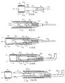
- Figure 6 is a view, partly in section, depicting an alternate mounting member 30 having a pair of extending electrical flexible cantilevered contacts 31 and 32. These are mounted by any conventional means on mounting shaft 33 which generally corresponds to mounting shaft 10 in Figures 1-3. Also seen in Figure 6 are two specially shaped pins 34 an 35 which are similar in shape and function to pins 13 and 14 described above. Also shown are conventional shaft extension 36 with conventional primary and secondary insulating coverings 37 and 38.
- Figure 7 is a side sectional view of a connectable member, e.g., disposable electrosurgical implement 40, adapted for engagement and mounting on the mounting member 30 of Figure 6.
- a connectable member e.g., disposable electrosurgical implement 40
- molded polymer section 41 within which there is fixed an electrosurgical electrode tip member 42.
- electrosurgical electrode tip member 42 At the proximal end 42a, there are provided a pair of sloping surfaces 42b and 42c which are adapted for engaging contacting surfaces 31a and 32a of cantilevered contacts 31 and 32 when electrosurgical implement 40 is telescoped into position on mounting shaft 33 as is shown in Figure 8.
- On the exterior of implement 40 is a layer of conventional insulation 43 which circumferentially surrounds the proximal portion of the implement as shown.
- apertures 44a and 44b extending through molded polymer 41 which may also extend through insulation 43 or may be covered over, thereby forming small recesses.
- the slots corresponding to slots 25a/25b of Figure 4 are not shown but are understood to function in like manner.
- two bifurcated springy sections 40a and 40b are provided.
- the electrosurgical implement 40 is shown in place and disengageably locked to mounting shaft 33. As described above in connection with Figures 1-5, this is accomplished by telescoping member 40 onto shaft 33 until it is fully engaged and pins 34 and 35 snapped into place within apertures 44a and 44b. Also as mentioned above, when it is desired to disengage telescoping member 40 from shaft 33, a twist of implement 40 causes spreading of finger-like sections 40a/40b by the pins 34 and 35 (due to their above-described rounded surfaces), thus causing the pins to be released from apertures 44a and 44b and resulting in their unlocking. Member 40 may then be entirely withdrawn from shaft 33 as described above with respect to Figures 1-5.
- Figure 9 is seen to be a side view, partly in section, depicting a different electrosurgical implement mounted on the mounting member of Figure 6; and Figure 10 is also a side view but showing the parts partly disassembled.
- Figure 10 is also a side view but showing the parts partly disassembled.
- the parts are similar to those of Figures 6, 7 and 8, and accordingly operate similarly. Attention is directed, however, to the difference in the way electrical contact is made.
- electrical contact is made between surfaces 32a and 42b.
Abstract
An electrosurgical electrode connector instrument for use in rapidly and easily connecting/disconnecting a disposable electrosurgical tip to and from a non-disposable mounting body. The non-disposable body includes a rod-like extension equipped with a pair of specially shaped projecting pins each having ramps and a curved surface. These pins are positioned on opposite sides of the rod-shaped extension. The disposable electrosurgical tip is provided at its proximal end with a tunnel-like recess having a pair of longitudinally disposed slots to define a pair of bifurcated cantilevered springy wall members each fitted with a small pin-locking aperture, thus adapting the disposable tip for telescopic engagement with the rod-like extension so that the recess of the disposable tip can be slid onto the rod-like extension with the specially shaped pins spreading the springy wall members slightly. After the tunnel-like recess has fully telescoped onto the aforementioned extension, the specially shaped pins snap into the pin-locking apertures to disengageably lock them in place. When it is desired to unlock the tip, the curved surfaces of the special geometrical characteristics of the pins make it possible to unlock the tip merely by a slight twist.
Description
- This invention relates to electrosurgical electrode connectors and more particularly to quick attachment/detachment connectors that are adapted for facilitating the attachment of working elements such as medical electrodes to members such as electrode holders, handles, or receptacles.
- As is known to those skilled in the art, there is a high level of concern in medical circles for improving cost effectiveness while maintaining acceptable levels of quality of medical services. One of the factors contributing to cost is the expense of providing and maintaining an acceptable level of cleanliness and sterilization. Techniques such as autoclaving for sterilizing medical equipment is time consuming; and for some medical instruments or parts thereof, it is not practicable. Accordingly, there has been a trend toward disposability of certain instruments. For others, where disposability is costly, it has become customary to make the instruments in parts which may be connected together for use. According to such proposals, parts such as operating handles are preserved and re-used, and other parts such as tips are discarded or are thoroughly sterilized after each use. Still others are sterilized and re-used a few number of times only. An example is that of the electrode disclosed in United States Patent Application Serial Number 08/342,215 filed November 18, 1994. Other examples of disconnectable parts for medical instruments are those set forth in German Offenlegungsschrift 2,404,764.
- The improved connection/disconnection device according to the invention hereof includes a rod-shaped main shaft extending from a handle or other support member. Spaced on opposite sides of the main shaft and extending outwardly therefrom, are a pair of specially shaped pins each having two small vertical surfaces, a non-horizontal surface such as a ramp extending generally downwardly in a direction toward the distal end of the main shaft and a radially curved surface. The connectable element (such as a medical electrode which may be disposable or non-disposable) has a connecting section that includes a tunnel-shaped recess having minutely larger interior dimensions than the corresponding exterior of the main supporting shaft, thus providing for a telescoping fit. On opposite sides of the tunnel shaped recess there are a pair of longitudinally extending slots adapted to partially divide the connectable element into two bifurcated finger-like sections each having a cantilevered spring-like quality. Also disposed in the finger-like sections of the connectable element are two generally rectangular apertures extending through its walls and spaced laterally between the two slots. These two apertures are positioned so as to engage the aforementioned pins when the connectable element is mounted on the shaft. Thus, when connection is made between the shaft and the connectable element, the aforementioned spring-like quality permits the interior surfaces of the finger-like sections to spread apart slightly as they ride up the aforementioned non-horizontal surfaces. When engagement has proceeded to the point where the pins reach the apertures, they snap thereinto, the spring-like force imparted by the finger-like sections retaining them in place until it is desired to achieve disconnection. Disconnection is accomplished by imparting a torque between the shaft and connectable element such as by twisting the connectable element slightly. When this occurs, the finger-like elements are spread slightly by the thrust imparted thereto as the interior surfaces of the finger-like elements ride up the aforementioned radially curved surfaces of the pins.
- It is one general object of the invention to improve quick disconnect connections.
- It is another object of the invention to improve dependability while simplifying quick disconnect connections.
- It is yet another object of the invention to facilitate ease of engagement/disengagement and mounting of disposable-or non-disposable medical instruments on mountings.
- Accordingly, in accordance with one feature of the invention, a pair of specially shaped pins are positioned on opposite sides of a rod-shaped mounting member thus facilitating dependable locking and unlocking of a connecting member thereupon.
- In accordance with another feature of the invention, a connectable member having a tunnel-shaped recess adapted to telescope with the rod-shaped mounting member is provided with a pair of longitudinally disposed parallel slots disposed on opposite sides thereby partially dividing the connectable member into two bifurcated sections, providing for cantilevered spring-like action and facilitating telescoping of the connectable member and mounting member into frictionally engaging relationship.
- In accordance with still another feature of the invention, the specially shaped pins cooperate with geometries of the connectable member to slightly spring apart the two bifurcated sections as the mounting member and the connectable member are engaged and telescoped thus providing spring force to lock the members together when the parts are fully engaged.
- In accordance with yet another feature of the invention, within each of the bifurcated sections there is provided a slot which is adapted for receiving and retaining a corresponding one of the aforementioned specially shaped pins when the parts are fully engaged thus releaseably locking the parts together when they are fully telescoped.
- In accordance with still another feature of the invention, the aforementioned radially shaped surface on each of the two pins is adapted for engagement with an inner surface of the corresponding one of the two bifurcated sections, thereby providing for disconnection by imparting a relative radial torque between the mount and connectable member that results in a force which slightly spreads apart the two bifurcated members to release the pins from the slots and permit disengagement.
- These and other objects and features of the invention will be apparent from the following description, by way of example of a preferred embodiment, with reference to the drawing.
-
- Figure 1 is a view depicting a mounting shaft with a pair specially shaped locking pins extending outwardly therefrom;
- Figure 2 is a top view of the mounting shaft of Figure 1;
- Figure 3 is a section taken along the section lines 3-3 of Figure 2;
- Figure 4 is a side elevation view of a bifurcated connectable member adapted for telescoping engagement with a mounting shaft such as that depicted in Figures 1-3;
- Figure 5 is a top view of the connectable member of Figure 4;
- Figure 6 is a view, partly in section, depicting an alternate mounting member having a pair of extending electrical contacts;
- Figure 7 is a side sectional view of a disposable electrosurgical implement adapted for engagement and mounting on the mounting member of Figure 6;
- Figure 8 is a side view, partly in section, depicting the disposable electrosurgical implement of Figure 7 mounted on the mounting member of Figure 6;
- Figure 9 is a side view, partly in section, depicting a different electrosurgical implement mounted on the mounting member of Figure 6; and
- Figure 10 is a view depicting the parts of Figure 9 partly disassembled.
- Now turning to the drawing, and more particularly Figure 1 thereof, it will seen to show a side elevation view of a rod-shaped mounting shaft 10 illustrating the principles of the instant invention. The shaft preferably is generally cylindrical and may include a bevelled surface such as surface 11. Alternatively, surface 11 may be rounded, it being the purpose of surface 11 to facilitate engagement with a mating female part such as that illustrated in Figures 4 and 5. Near
proximal end 12 there are provided a pair of projectingpins ramps 15a/15b that slope upwardly, but which can also curvilinearly extend upwardly, in the direction ofproximal end 12 and terminate at a first pair ofvertical cliff surfaces 13a and 14a. Each of these pins is specially shaped as will be evident from Figures 1 and 3; and each is either an integral extension of shaft 10 (preferably) or is rigidly affixed thereto. By effectively making the pins integral extensions of shaft 10, cleansing of the shaft and pins is facilitated. - Figure 2 is a top view of the cylindrical mounting shaft 10 of Figure 1. There, it will be seen, are
surfaces 10a, 11,proximal end 12,distal end 19 and projectingpin 13. - Figure 3 is a section taken along the section lines 3-3 of Figure 2. There, in Figure 3, are illustrated the specially
shaped pins vertical surfaces 17a/17b (the first set being those designated 13a/14a in Figure 1) essentially at right angles to the adjoining surface of mounting shaft 10; and a curved surface (surfaces 18a/18b) at the opposite side and extending upwardly and over to the tops of thecliffs 17a/17b respectively. It will thus be seen that the specially-shaped pins sloping ramp 15a/15b, a first cliff-like surface 13a/14a (Figure 1), a second vertical cliff-like surface 17a/17b (Figure 3) and arounded surface 18a/18b. - As mentioned above, the electrosurgical connector according to the invention includes a connectable member adapted for mounting on the exterior surface of mounting shaft 10. One such connectable member 20 is depicted in Figure 4 where there is shown beginning at the
proximal end 21 thereof acylindrical recess 22 extending as defined by dashed line 23. As will be evident from the remaining description,recess 22 is adapted for telescoping onto mounting shaft 10. Thus,recess 22 is preferably principally cylindrical except for its distal extremity which is preferably, though not necessarily, rounded as shown. Longitudinally extending fromproximal end 21 towarddistal end 24 alongrecess 22 for a predetermined distance less than the full distance between proximal anddistal ends sections 26a/26b projecting toproximal end 21 from their joinder to distalend 24 atregion 27. Also shown are a pair ofapertures 28a/28b which are provided for engagingprojecting pins - Figure 5 is a top view of the connectable member illustrated in Figure 4. There, it will be observed, are member 20 with
proximal end 21, longitudinally extending tunnel-like recess 22,distal end 24, bifurcatedsection 26a andaperture 28a. - When it is desired to mount and disengageably lock connectable member 20 onto mounting shaft 10,
proximal end 21 of connectable member 20 is brought into alignment withdistal end 19 of mounting shaft 10. It is then telescoped thereupon so that the inner surface of member 20 as defined by dashed line 23 loosely and slideably engagesouter surface 10a of shaft 10. However, when telescoping has proceeded to a point at which inner surface 23 engagesramps 15a/15b ofpins bifurcated parts 26a/26b as the interior surfaces ride up the ramps. After they have reached the upper limit of the ramps and progressed along the interior surfaces ofparts 26a/26b to a point where the pins have reachedapertures 28a/28b, the pins snap into the apertures, whereuponparts 26a/26b spring back into their quiescent conditions in which they are fitted onto mounting shaft 10. - As mentioned above, when it is desired to disconnect the two parts, disengagement is accomplished by imparting a torque between the mounting shaft 10 and connectable element 20 such as by twisting the connectable element slightly. When this occurs, due to the
curved surfaces 18a/18b of the pins, the finger-like elements 26a/26b are spread by the thrust imparted thereto as the pins exit fromapertures 28a/28b, the interior surfaces of the finger-like elements riding up the aforementioned radially curvedsurface 18a/18b of thepins - Figure 6 is a view, partly in section, depicting an alternate mounting
member 30 having a pair of extending electrical flexiblecantilevered contacts shaft 33 which generally corresponds to mounting shaft 10 in Figures 1-3. Also seen in Figure 6 are two specially shapedpins 34 an 35 which are similar in shape and function topins conventional shaft extension 36 with conventional primary and secondary insulatingcoverings - Figure 7 is a side sectional view of a connectable member, e.g., disposable electrosurgical implement 40, adapted for engagement and mounting on the mounting
member 30 of Figure 6. There, it will be seen, are moldedpolymer section 41 within which there is fixed an electrosurgical electrode tip member 42. At the proximal end 42a, there are provided a pair of slopingsurfaces 42b and 42c which are adapted for engaging contactingsurfaces cantilevered contacts shaft 33 as is shown in Figure 8. On the exterior of implement 40 is a layer ofconventional insulation 43 which circumferentially surrounds the proximal portion of the implement as shown. Also seen in Figure 7 areapertures polymer 41 which may also extend throughinsulation 43 or may be covered over, thereby forming small recesses. To avoid repetition and to preserve clarity of presentation, the slots corresponding to slots 25a/25b of Figure 4 are not shown but are understood to function in like manner. Thus there are provided two bifurcated springy sections 40a and 40b. - Now turning to Figure 8, the electrosurgical implement 40 is shown in place and disengageably locked to mounting
shaft 33. As described above in connection with Figures 1-5, this is accomplished by telescoping member 40 ontoshaft 33 until it is fully engaged and pins 34 and 35 snapped into place withinapertures shaft 33, a twist of implement 40 causes spreading of finger-like sections 40a/40b by thepins 34 and 35 (due to their above-described rounded surfaces), thus causing the pins to be released fromapertures shaft 33 as described above with respect to Figures 1-5. - Figure 9 is seen to be a side view, partly in section, depicting a different electrosurgical implement mounted on the mounting member of Figure 6; and Figure 10 is also a side view but showing the parts partly disassembled. However except for geometry and placement of
electrode tip 42d, the off-center axis thereof with respect to the central axis of the mounting, and the electrical contact betweensurface 32a andsurface 42b (Figure 10) the parts are similar to those of Figures 6, 7 and 8, and accordingly operate similarly. Attention is directed, however, to the difference in the way electrical contact is made. In the off-center line arrangement of Figures 9 and 10, electrical contact is made betweensurfaces - It will now be evident that there has herein been described an improved quick-connect-disconnect mounting that is particularly adapted for medical and attendant uses in which a mounting portion is reusable while a tip portion is disposable.
- Although the invention hereof has been described by way of a preferred embodiment, it will be evident that other adaptations and modifications may be employed without departing from the spirit and scope thereof. For example, one or more additional pins could be employed, and the total number of pins then deployed at spaced intervals about the exterior of the mounting shaft. Moreover, the parts could be made with at least partially non-cylindrical geometries.
- While the invention has been described in connection with a preferred embodiment, it is not intended to limit the scope of the invention to the particular form set forth, but on the contrary, it is intended to cover such alternatives, modifications, and equivalents as may be included within the spirit and scope of the invention as defined by the appended claims.
- It should be noted that the objects and advantages of the invention may be attained by means of any compatible combination(s) particularly pointed out in the items of the following summary of the invention and the appended claims.
- The invention can be summarized as follows:
- 1. An electrosurgical electrode connector element comprising a mounting member having an extending shaft with an exterior surface, said extending shaft including:
- (a) a proximal end and a distal end;
- (b) a first pin having a first plurality of outer surfaces, said first pin being affixed to said exterior surface of said shaft;
- (c) a second pin having a second plurality of outer surfaces similar to said first plurality of outer surfaces, said second pin being affixed to said exterior surface of said shaft, said first and said second pluralities of said outer surfaces of said first and said second pins each having a rounded surface, a ramp starting at said exterior surface of said shaft and an essentially vertical cliff extending to said exterior surface of said shaft.
- 2. An electrosurgical electrode connector element
wherein said first and said second pins are integral with said extending shaft. - 3. An electrosurgical electrode connector element
wherein said sloping ramp is essentially planar. - 4. An electrosurgical electrode connecter element
wherein said ramp is disposed on said shaft so that said ramp extends upwardly in the direction of said proximal end of said shaft. - 5. An electrosurgical electrode connector element
wherein said cliff is essentially vertical with respect to adjacent surface of said shaft. - 6. An electrosurgical electrode connector element
wherein each of said pins includes another cliff and wherein said rounded surface begins on an opposite side of said pin from said another cliff. - 7. An electrosurgical electrode connector comprising:
- (a) A mounting member having an extending shaft with an exterior surface, said extending shaft including:
- (i) a proximal end and a distal end;
- (ii) a first pin having a first plurality of outer surfaces, said first pin being affixed to said exterior surface of said shaft;
- (iii) a second pin having a second plurality of outer surfaces similar to said first plurality of outer surfaces, said second pin being affixed to said exterior surface of said shaft, said first and said second pluralities of said outer surfaces of said first and said second pins each having a rounded surface, a ramp starting at said exterior surface of said shaft, and an essentially vertical cliff extending to said exterior surface of said shaft;
- (b) a connectable member adapted for mounting on said exterior surface of said extending shaft, said connectable member having an elongated tunnel-like recess at its proximal end adapted for telescoping engagement with said exterior surface of said extending shaft; and
- (c) locking means including said pins effective when said connectable member is telescoped onto said extending shaft for disengageably locking said connectable member onto said extending shaft.
- (a) A mounting member having an extending shaft with an exterior surface, said extending shaft including:
- 8. An electrosurgical electrode connector element
wherein said locking means includes spring means. - 9. An electrosurgical electrode connector element
wherein said ramp is essentially planar. - 10. An electrosurgical electrode connector element
wherein said ramp is disposed on said shaft so that said ramp extends upwardly in the direction of said proximal end of said shaft. - 11. An electrosurgical electrode connector element
wherein said cliff is essentially vertical with respect to adjacent surface of said shaft. - 12. An electrosurgical electrode connector element
wherein each of said pins includes another cliff and wherein said rounded surface begins on an opposite side of said pin from said another cliff. - 13. An electrosurgical electrode connector
in which said first and said second pins are positioned circumferentially on opposite sides of said exterior surface of said shaft. - 14. An electrosurgical electrode connector
wherein said connectable member includes:- (i) a proximal end and a distal end; and
- (ii) slots extending from said proximal end forward toward said distal end a predetermined distance less than the entire distance between said proximal and said distal ends to define first and second bifurcated walls of said tunnel-like recess.
- 15. An electrosurgical electrode connector
wherein said first wall includes a first aperture therein, said second wall includes a second aperture therein, said first and said second apertures being positioned essentially circumferentially on opposite sides of said recess. - 16. An electrosurgical electrode connector
wherein said locking means is effective to extend said first pin into said first aperture and said second pin into said second aperture thereby to disengagably lock said connectable member to said mounting member. - 17. An electrosurgical electrode connector
in which said mounting member is non-disposable. - 18. An electrosurgical electrode connector
in which said connectable member is disposable. - 19. An electrosurgical electrode connector
in which said mounting member is non-disposable and said connectable member is disposable. - 20. An electrosurgical electrode connector comprising:
- (a) A mounting member having an extending shaft with an exterior surface, said extending shaft including:
- (i) a proximal end and a distal end;
- (ii) a first pin having a first plurality of outer surfaces, said first pin being affixed to said exterior surface of said shaft;
- (iii) a second pin having a second plurality of outer surfaces similar to said first plurality of outer surfaces, said second pin being affixed to said exterior surface of said shaft, said first and said second pluralities of said outer surfaces of said first and said second pins each having:
- (1) a rounded surface,
- (2) a ramp planar surface extending upwardly toward said proximal end of said extending shaft,
- (3) a first cliff having a planar surface essentially vertical with respect to immediately adjacent surface of said shaft,
- (4) a second cliff having a planar surface essentially vertical with respect to immediately adjacent surface of said shaft, the plane of said second cliff being essentially at right angles to the plane of said first cliff, and
- (5) a rounded surface disposed on a side of said pin beginning at an opposite side to that of said second cliff, said first and said second pins being positioned circumferentially on opposite sides of said exterior cylindrical surface;
- (b) a connectable member adapted for mounting on said exterior surface of said extending shaft, said connectable member having a proximal end and a distal end, a tunnel-like recess at its proximal end having a slot extending from said proximal end forward toward said distal end a predetermined distance less than the entire distance between said proximal and said distal ends to define first and second bifurcated walls of said tunnel-like recess and adapting said connectable member for telescoping engagement with said exterior surface of said extending shaft, said first wall having a first aperture therein and said second wall having a second aperture therein; and
- (c) locking means including said pins and said apertures effective when said connectable member is telescoped onto said extending shaft for disengageably locking said connectable member onto said extending shaft.
- (a) A mounting member having an extending shaft with an exterior surface, said extending shaft including:
Claims (14)
- An electrosurgical electrode connector element comprising a mounting member having an extending shaft with an exterior surface, said extending shaft including:(a) a proximal end and a distal end;(b) a first pin having a first plurality of outer surfaces, said first pin being affixed to said exterior surface of said shaft;(c) a second pin having a second plurality of outer surfaces similar to said first plurality of outer surfaces, said second pin being affixed to said exterior surface of said shaft, said first and said second pluralities of said outer surfaces of said first and said second pins each having a rounded surface, a ramp starting at said exterior surface of said shaft and an essentially vertical cliff extending to said exterior surface of said shaft.
- An electrosurgical electrode connector element according to Claim 1 wherein said first and said second pins are integral with said extending shaft, wherein preferably said sloping ramp is essentially planar, and wherein preferably said ramp is disposed on said shaft so that said ramp extends upwardly in the direction of said proximal end of said shaft.
- An electrosurgical electrode connector comprising:(a) A mounting member having an extending shaft with an exterior surface, said extending shaft including:(i) a proximal end and a distal end;(ii) a first pin having a first plurality of outer surfaces, said first pin being affixed to said exterior surface of said shaft;(iii) a second pin having a second plurality of outer surfaces similar to said first plurality of outer surfaces, said second pin being affixed to said exterior surface of said shaft, said first and said second pluralities of said outer surfaces of said first and said second pins each having a rounded surface, a ramp starting at said exterior surface of said shaft, and an essentially vertical cliff extending to said exterior surface of said shaft;(b) a connectable member adapted for mounting on said exterior surface of said extending shaft, said connectable member having an elongated tunnel-like recess at its proximal end adapted for telescoping engagement with said exterior surface of said extending shaft; and(c) locking means including said pins effective when said connectable member is telescoped onto said extending shaft for disengageably locking said connectable member onto said extending shaft.
- An electrosurgical electrode connector element according to one or more of the preceeding Claims wherein said locking means includes spring means, wherein preferably said ramp is essentially planar, and wherein preferably said ramp is disposed on said shaft so that said ramp extends upwardly in the direction of said proximal end of said shaft.
- An electrosurgical electrode connector element according to one or more of the preceeding Claims wherein said cliff is essentially vertical with respect to adjacent surface of said shaft.
- An electrosurgical electrode connector element according to one or more of the preceeding Claims wherein each of said pins includes another cliff and wherein said rounded surface begins on an opposite side of said pin from said another cliff.
- An electrosurgical electrode connector according to one or more of the preceeding Claims in which said first and said second pins are positioned circumferentially on opposite sides of said exterior surface of said shaft.
- An electrosurgical electrode connector according to Claim 7 wherein said connectable member includes:(i) a proximal end and a distal end; and(ii) slots extending from said proximal end forward toward said distal end a predetermined distance less than the entire distance between said proximal and said distal ends to define first and second bifurcated walls of said tunnel-like recess, and
- An electrosurgical electrode connector according to one or more of the preceeding Claims wherein said first wall includes a first aperture therein, said second wall includes a second aperture therein, said first and said second apertures being positioned essentially circumferentially on opposite sides of said recess. wherein preferably said locking means is effective to extend said first pin into said first aperture and said second pin into said second aperture thereby to disengagably lock said connectable member to said mounting member.
- An electrosurgical electrode connector according to one or more of the preceeding Claims in which said mounting member is non-disposable.
- An electrosurgical electrode connector according to one or more of the preceeding Claims in which said connectable member is disposable.
- An electrosurgical electrode connector according to one or more of the preceeding Claims in which said mounting member is non-disposable and said connectable member is disposable.
- An electrosurgical electrode connector comprising:(a) A mounting member having an extending shaft with an exterior surface, said extending shaft including:(i) a proximal end and a distal end;(ii) a first pin having a first plurality of outer surfaces, said first pin being affixed to said exterior surface of said shaft;(iii) a second pin having a second plurality of outer surfaces similar to said first plurality of outer surfaces, said second pin being affixed to said exterior surface of said shaft, said first and said second pluralities of said outer surfaces of said first and said second pins each having:(1) a rounded surface,(2) a ramp planar surface extending upwardly toward said proximal end of said extending shaft,(3) a first cliff having a planar surface essentially vertical with respect to immediately adjacent surface of said shaft,(4) a second cliff having a planar surface essentially vertical with respect to immediately adjacent surface of said shaft, the plane of said second cliff being essentially at right angles to the plane of said first cliff, and(5) a rounded surface disposed on a side of said pin beginning at an opposite side to that of said second cliff, said first and said second pins being positioned circumferentially on opposite sides of said exterior cylindrical surface;(b) a connectable member adapted for mounting on said exterior surface of said extending shaft, said connectable member having a proximal end and a distal end, a tunnel-like recess at its proximal end having a slot extending from said proximal end forward toward said distal end a predetermined distance less than the entire distance between said proximal and said distal ends to define first and second bifurcated walls of said tunnel-like recess and adapting said connectable member for telescoping engagement with said exterior surface of said extending shaft, said first wall having a first aperture therein and said second wall having a second aperture therein; and(c) locking means including said pins and said apertures effective when said connectable member is telescoped onto said extending shaft for disengageably locking said connectable member onto said extending shaft.
- An electrosurgical electrode connector element comprising a mounting member having a shaft with an exterior surface, said shaft including:(a) a proximal end and a distal end; and(b) a pin having a first plurality of outer surfaces, said first pin being affixed to said exterior surface of said shaft.
Applications Claiming Priority (2)
| Application Number | Priority Date | Filing Date | Title |
|---|---|---|---|
| US555577 | 1995-11-08 | ||
| US08/555,577 US5885280A (en) | 1995-11-08 | 1995-11-08 | Electrosurgical electrode connector |
Publications (1)
| Publication Number | Publication Date |
|---|---|
| EP0773003A1 true EP0773003A1 (en) | 1997-05-14 |
Family
ID=24217807
Family Applications (1)
| Application Number | Title | Priority Date | Filing Date |
|---|---|---|---|
| EP96116167A Withdrawn EP0773003A1 (en) | 1995-11-08 | 1996-10-09 | Electrosurgical electrode connector |
Country Status (8)
| Country | Link |
|---|---|
| US (1) | US5885280A (en) |
| EP (1) | EP0773003A1 (en) |
| JP (1) | JPH09131352A (en) |
| KR (1) | KR970025566A (en) |
| CN (1) | CN1150010A (en) |
| AU (1) | AU715569B2 (en) |
| NZ (1) | NZ299132A (en) |
| TW (1) | TW353608B (en) |
Cited By (16)
| Publication number | Priority date | Publication date | Assignee | Title |
|---|---|---|---|---|
| WO2014022222A2 (en) * | 2012-08-02 | 2014-02-06 | Ethicon Endo-Surgery, Inc. | Reusable electrode and disposable sheath |
| US9277957B2 (en) | 2012-08-15 | 2016-03-08 | Ethicon Endo-Surgery, Inc. | Electrosurgical devices and methods |
| US9375268B2 (en) | 2007-02-15 | 2016-06-28 | Ethicon Endo-Surgery, Inc. | Electroporation ablation apparatus, system, and method |
| CN106450818A (en) * | 2016-08-30 | 2017-02-22 | 青岛光电医疗科技有限公司 | Disposable anti-noise shielding electrode connector |
| US9788888B2 (en) | 2012-07-03 | 2017-10-17 | Ethicon Endo-Surgery, Inc. | Endoscopic cap electrode and method for using the same |
| US9883910B2 (en) | 2011-03-17 | 2018-02-06 | Eticon Endo-Surgery, Inc. | Hand held surgical device for manipulating an internal magnet assembly within a patient |
| US10004558B2 (en) | 2009-01-12 | 2018-06-26 | Ethicon Endo-Surgery, Inc. | Electrical ablation devices |
| US10098691B2 (en) | 2009-12-18 | 2018-10-16 | Ethicon Endo-Surgery, Inc. | Surgical instrument comprising an electrode |
| US10098527B2 (en) | 2013-02-27 | 2018-10-16 | Ethidcon Endo-Surgery, Inc. | System for performing a minimally invasive surgical procedure |
| US10105141B2 (en) | 2008-07-14 | 2018-10-23 | Ethicon Endo-Surgery, Inc. | Tissue apposition clip application methods |
| US10206709B2 (en) | 2012-05-14 | 2019-02-19 | Ethicon Llc | Apparatus for introducing an object into a patient |
| US10258406B2 (en) | 2011-02-28 | 2019-04-16 | Ethicon Llc | Electrical ablation devices and methods |
| US10278761B2 (en) | 2011-02-28 | 2019-05-07 | Ethicon Llc | Electrical ablation devices and methods |
| US10314603B2 (en) | 2008-11-25 | 2019-06-11 | Ethicon Llc | Rotational coupling device for surgical instrument with flexible actuators |
| US10314649B2 (en) | 2012-08-02 | 2019-06-11 | Ethicon Endo-Surgery, Inc. | Flexible expandable electrode and method of intraluminal delivery of pulsed power |
| US10492880B2 (en) | 2012-07-30 | 2019-12-03 | Ethicon Llc | Needle probe guide |
Families Citing this family (15)
| Publication number | Priority date | Publication date | Assignee | Title |
|---|---|---|---|---|
| US7235073B2 (en) | 2000-07-06 | 2007-06-26 | Ethicon Endo-Surgery, Inc. | Cooled electrosurgical forceps |
| US6501993B2 (en) | 2001-03-27 | 2002-12-31 | Pacesetter, Inc. | Electrode assembly with a detachable distal tip |
| US6853667B2 (en) * | 2001-06-11 | 2005-02-08 | Honeywell International, Inc. | Electrode design to extend sputter life of a ring laser gyroscope |
| US6527567B1 (en) * | 2002-06-21 | 2003-03-04 | Guadalupe Aguirre, Jr. | Locking jack cover system |
| US20040115477A1 (en) * | 2002-12-12 | 2004-06-17 | Bruce Nesbitt | Coating reinforcing underlayment and method of manufacturing same |
| US7147634B2 (en) * | 2005-05-12 | 2006-12-12 | Orion Industries, Ltd. | Electrosurgical electrode and method of manufacturing same |
| US8814861B2 (en) | 2005-05-12 | 2014-08-26 | Innovatech, Llc | Electrosurgical electrode and method of manufacturing same |
| DE102006043574A1 (en) * | 2006-09-16 | 2008-03-27 | Hirschmann Automation And Control Gmbh | Solar connector with improved locking means |
| US20110098704A1 (en) | 2009-10-28 | 2011-04-28 | Ethicon Endo-Surgery, Inc. | Electrical ablation devices |
| US8197276B2 (en) | 2010-08-13 | 2012-06-12 | Djo, Llc | Low profile connector system |
| JP2012070933A (en) * | 2010-09-28 | 2012-04-12 | Olympus Corp | Attachment and detachment mechanism, and operation tool system |
| US9474424B2 (en) * | 2012-06-01 | 2016-10-25 | Bissell Homecare, Inc. | Surface cleaning apparatus |
| US11234760B2 (en) * | 2012-10-05 | 2022-02-01 | Medtronic Advanced Energy Llc | Electrosurgical device for cutting and removing tissue |
| TWI594722B (en) * | 2015-01-13 | 2017-08-11 | 瑪格戴恩醫療產品公司 | Electrosurgical electrode adapted for use in performing electrosurgical operative procedures |
| US10158195B2 (en) | 2016-10-26 | 2018-12-18 | Heartware, Inc. | Grooved connector with land bridge |
Citations (3)
| Publication number | Priority date | Publication date | Assignee | Title |
|---|---|---|---|---|
| DE2404764A1 (en) * | 1973-03-12 | 1974-09-19 | Whaledent Inc | PROBE UNIT FOR ELECTRO-MEDICAL EQUIPMENT |
| US3961630A (en) * | 1973-11-12 | 1976-06-08 | Dentsply Research & Development Corporation | Protective circuit for radio-frequency electrosurgical device |
| WO1981000200A1 (en) * | 1979-07-16 | 1981-02-05 | J Esty | Disposable electrosurgical instrument |
Family Cites Families (16)
| Publication number | Priority date | Publication date | Assignee | Title |
|---|---|---|---|---|
| US176069A (en) * | 1876-04-11 | Improvement in couplings for train-telegraphs | ||
| US278346A (en) * | 1883-05-29 | Harry e | ||
| US490831A (en) * | 1893-01-31 | Heinrich lxhers | ||
| US1221524A (en) * | 1916-04-20 | 1917-04-03 | Frankel Connector Company Inc | Extension attachment for testing-clips. |
| US1851843A (en) * | 1928-12-04 | 1932-03-29 | Dee F Inman | Rod coupler |
| US1869181A (en) * | 1929-09-06 | 1932-07-26 | Bell Telephone Labor Inc | Electric test connecter |
| US1916722A (en) * | 1931-06-15 | 1933-07-04 | Frank M Ende | Diathermy |
| US2554876A (en) * | 1948-10-02 | 1951-05-29 | Kenneth T Snow | Electrical connection having identical, bifurcated plate members |
| FR1241174A (en) * | 1959-08-01 | 1960-09-16 | Improvements to disconnected electrical junction terminals | |
| US3144804A (en) * | 1961-06-30 | 1964-08-18 | Wedgelock Corp Of California | Anchoring structure for releasable fastener pins |
| US3256031A (en) * | 1963-07-31 | 1966-06-14 | Dominion Electric Corp | Coupling structure |
| US4255007A (en) * | 1978-05-12 | 1981-03-10 | Trw Inc. | Multi-terminal rotary connector |
| US4562838A (en) * | 1981-01-23 | 1986-01-07 | Walker William S | Electrosurgery instrument |
| US4657016A (en) * | 1984-08-20 | 1987-04-14 | Garito Jon C | Electrosurgical handpiece for blades, needles and forceps |
| US5035695A (en) * | 1987-11-30 | 1991-07-30 | Jaroy Weber, Jr. | Extendable electrocautery surgery apparatus and method |
| US5257635A (en) * | 1988-11-25 | 1993-11-02 | Sensor Electronics, Inc. | Electrical heating catheter |
-
1995
- 1995-11-08 US US08/555,577 patent/US5885280A/en not_active Expired - Fee Related
-
1996
- 1996-08-07 NZ NZ299132A patent/NZ299132A/en unknown
- 1996-08-30 CN CN96109610A patent/CN1150010A/en active Pending
- 1996-09-03 TW TW085110755A patent/TW353608B/en active
- 1996-10-09 EP EP96116167A patent/EP0773003A1/en not_active Withdrawn
- 1996-10-15 JP JP8272123A patent/JPH09131352A/en active Pending
- 1996-10-21 AU AU70330/96A patent/AU715569B2/en not_active Ceased
- 1996-11-08 KR KR1019960052933A patent/KR970025566A/en active IP Right Grant
Patent Citations (3)
| Publication number | Priority date | Publication date | Assignee | Title |
|---|---|---|---|---|
| DE2404764A1 (en) * | 1973-03-12 | 1974-09-19 | Whaledent Inc | PROBE UNIT FOR ELECTRO-MEDICAL EQUIPMENT |
| US3961630A (en) * | 1973-11-12 | 1976-06-08 | Dentsply Research & Development Corporation | Protective circuit for radio-frequency electrosurgical device |
| WO1981000200A1 (en) * | 1979-07-16 | 1981-02-05 | J Esty | Disposable electrosurgical instrument |
Cited By (22)
| Publication number | Priority date | Publication date | Assignee | Title |
|---|---|---|---|---|
| US10478248B2 (en) | 2007-02-15 | 2019-11-19 | Ethicon Llc | Electroporation ablation apparatus, system, and method |
| US9375268B2 (en) | 2007-02-15 | 2016-06-28 | Ethicon Endo-Surgery, Inc. | Electroporation ablation apparatus, system, and method |
| US10105141B2 (en) | 2008-07-14 | 2018-10-23 | Ethicon Endo-Surgery, Inc. | Tissue apposition clip application methods |
| US10314603B2 (en) | 2008-11-25 | 2019-06-11 | Ethicon Llc | Rotational coupling device for surgical instrument with flexible actuators |
| US10004558B2 (en) | 2009-01-12 | 2018-06-26 | Ethicon Endo-Surgery, Inc. | Electrical ablation devices |
| US10098691B2 (en) | 2009-12-18 | 2018-10-16 | Ethicon Endo-Surgery, Inc. | Surgical instrument comprising an electrode |
| US10258406B2 (en) | 2011-02-28 | 2019-04-16 | Ethicon Llc | Electrical ablation devices and methods |
| US10278761B2 (en) | 2011-02-28 | 2019-05-07 | Ethicon Llc | Electrical ablation devices and methods |
| US9883910B2 (en) | 2011-03-17 | 2018-02-06 | Eticon Endo-Surgery, Inc. | Hand held surgical device for manipulating an internal magnet assembly within a patient |
| US10206709B2 (en) | 2012-05-14 | 2019-02-19 | Ethicon Llc | Apparatus for introducing an object into a patient |
| US9788888B2 (en) | 2012-07-03 | 2017-10-17 | Ethicon Endo-Surgery, Inc. | Endoscopic cap electrode and method for using the same |
| US10492880B2 (en) | 2012-07-30 | 2019-12-03 | Ethicon Llc | Needle probe guide |
| US9572623B2 (en) | 2012-08-02 | 2017-02-21 | Ethicon Endo-Surgery, Inc. | Reusable electrode and disposable sheath |
| WO2014022222A3 (en) * | 2012-08-02 | 2014-12-24 | Ethicon Endo-Surgery, Inc. | Reusable electrode and disposable sheath |
| WO2014022222A2 (en) * | 2012-08-02 | 2014-02-06 | Ethicon Endo-Surgery, Inc. | Reusable electrode and disposable sheath |
| US10314649B2 (en) | 2012-08-02 | 2019-06-11 | Ethicon Endo-Surgery, Inc. | Flexible expandable electrode and method of intraluminal delivery of pulsed power |
| US9788885B2 (en) | 2012-08-15 | 2017-10-17 | Ethicon Endo-Surgery, Inc. | Electrosurgical system energy source |
| US9277957B2 (en) | 2012-08-15 | 2016-03-08 | Ethicon Endo-Surgery, Inc. | Electrosurgical devices and methods |
| US10342598B2 (en) | 2012-08-15 | 2019-07-09 | Ethicon Llc | Electrosurgical system for delivering a biphasic waveform |
| US10098527B2 (en) | 2013-02-27 | 2018-10-16 | Ethidcon Endo-Surgery, Inc. | System for performing a minimally invasive surgical procedure |
| CN106450818A (en) * | 2016-08-30 | 2017-02-22 | 青岛光电医疗科技有限公司 | Disposable anti-noise shielding electrode connector |
| CN106450818B (en) * | 2016-08-30 | 2018-11-13 | 青岛光电医疗科技有限公司 | Disposable anti-noise, bucking electrode connector |
Also Published As
| Publication number | Publication date |
|---|---|
| TW353608B (en) | 1999-03-01 |
| JPH09131352A (en) | 1997-05-20 |
| AU715569B2 (en) | 2000-02-03 |
| AU7033096A (en) | 1997-05-15 |
| CN1150010A (en) | 1997-05-21 |
| NZ299132A (en) | 1997-09-22 |
| KR970025566A (en) | 1997-06-24 |
| US5885280A (en) | 1999-03-23 |
Similar Documents
| Publication | Publication Date | Title |
|---|---|---|
| US5885280A (en) | Electrosurgical electrode connector | |
| EP0698377A1 (en) | Medical electrode insulating system | |
| US7090525B1 (en) | Electrical connector including snap-in lanyard | |
| US5109452A (en) | Electrical-optical hybrid connector | |
| AU643065B2 (en) | Hinged electrical connector | |
| EP0538994A1 (en) | Bipolar laparoscopic instrument with replaceable electrode tip assembly | |
| EP0598459A2 (en) | Electrode for stimulating and/or detecting the muscle activity of muscles or muscle groups of a patient, which are accessible through a body orifice | |
| AU2006214647A2 (en) | Snap lock connector | |
| EP1009302A1 (en) | Bipolar electrosurgical device | |
| GB2412322A (en) | High frequency treatment instrument for endoscope | |
| CA3021629C (en) | Unipolar cannula | |
| JP7224401B2 (en) | Hand-held surgical instrument, insulating insert for hand-held surgical instrument, and method of operating hand-held surgical instrument | |
| GB2559947A (en) | Electrical connector | |
| EP0031228A1 (en) | Instrument for collecting tissue cells | |
| PT1673011E (en) | Fetal heart rate monitoring assembly | |
| WO1997042894A1 (en) | Electro-surgical instrument with spline connection | |
| KR100767265B1 (en) | Connector for electrical connection | |
| US6088609A (en) | Apparatus and method for monitoring a fetus | |
| CN112334177A (en) | Multi-row sharp tooth grabber | |
| EP0910435B1 (en) | Electrical female connector, especially for an implantable heart stimulator | |
| US20080171948A1 (en) | Subdermal needles | |
| CN219183643U (en) | Endoscope connector with detachable locking mechanism and endoscope system | |
| EP0924803A2 (en) | Electrical contact with multiple points of contact | |
| JP3197198B2 (en) | Endoscope connection structure | |
| EP0312231A2 (en) | Electrical receptacle terminal connector with visually inspectable components |
Legal Events
| Date | Code | Title | Description |
|---|---|---|---|
| PUAI | Public reference made under article 153(3) epc to a published international application that has entered the european phase |
Free format text: ORIGINAL CODE: 0009012 |
|
| AK | Designated contracting states |
Kind code of ref document: A1 Designated state(s): DE FR GB IT |
|
| 17P | Request for examination filed |
Effective date: 19971031 |
|
| 17Q | First examination report despatched |
Effective date: 20020227 |
|
| STAA | Information on the status of an ep patent application or granted ep patent |
Free format text: STATUS: THE APPLICATION IS DEEMED TO BE WITHDRAWN |
|
| 18D | Application deemed to be withdrawn |
Effective date: 20020710 |