EP0772843B1 - Procedure for identification of objects based on forming and verifying their surface roughness as well as objects suitable to be identified - Google Patents
Procedure for identification of objects based on forming and verifying their surface roughness as well as objects suitable to be identified Download PDFInfo
- Publication number
- EP0772843B1 EP0772843B1 EP95925082A EP95925082A EP0772843B1 EP 0772843 B1 EP0772843 B1 EP 0772843B1 EP 95925082 A EP95925082 A EP 95925082A EP 95925082 A EP95925082 A EP 95925082A EP 0772843 B1 EP0772843 B1 EP 0772843B1
- Authority
- EP
- European Patent Office
- Prior art keywords
- marking
- identification
- dimensional marking
- surface roughness
- produced
- Prior art date
- Legal status (The legal status is an assumption and is not a legal conclusion. Google has not performed a legal analysis and makes no representation as to the accuracy of the status listed.)
- Expired - Lifetime
Links
Images

Classifications
-
- G—PHYSICS
- G06—COMPUTING; CALCULATING OR COUNTING
- G06K—GRAPHICAL DATA READING; PRESENTATION OF DATA; RECORD CARRIERS; HANDLING RECORD CARRIERS
- G06K19/00—Record carriers for use with machines and with at least a part designed to carry digital markings
- G06K19/06—Record carriers for use with machines and with at least a part designed to carry digital markings characterised by the kind of the digital marking, e.g. shape, nature, code
- G06K19/08—Record carriers for use with machines and with at least a part designed to carry digital markings characterised by the kind of the digital marking, e.g. shape, nature, code using markings of different kinds or more than one marking of the same kind in the same record carrier, e.g. one marking being sensed by optical and the other by magnetic means
- G06K19/10—Record carriers for use with machines and with at least a part designed to carry digital markings characterised by the kind of the digital marking, e.g. shape, nature, code using markings of different kinds or more than one marking of the same kind in the same record carrier, e.g. one marking being sensed by optical and the other by magnetic means at least one kind of marking being used for authentication, e.g. of credit or identity cards
- G06K19/16—Record carriers for use with machines and with at least a part designed to carry digital markings characterised by the kind of the digital marking, e.g. shape, nature, code using markings of different kinds or more than one marking of the same kind in the same record carrier, e.g. one marking being sensed by optical and the other by magnetic means at least one kind of marking being used for authentication, e.g. of credit or identity cards the marking being a hologram or diffraction grating
-
- B—PERFORMING OPERATIONS; TRANSPORTING
- B23—MACHINE TOOLS; METAL-WORKING NOT OTHERWISE PROVIDED FOR
- B23H—WORKING OF METAL BY THE ACTION OF A HIGH CONCENTRATION OF ELECTRIC CURRENT ON A WORKPIECE USING AN ELECTRODE WHICH TAKES THE PLACE OF A TOOL; SUCH WORKING COMBINED WITH OTHER FORMS OF WORKING OF METAL
- B23H9/00—Machining specially adapted for treating particular metal objects or for obtaining special effects or results on metal objects
- B23H9/06—Marking or engraving
Definitions
- the invention relates to a method for identification of objects and an object therefor.
- W091/14217 and EP-A-0 252 842 are concerned with respective processes for making embossing punches for the manufacture of watermarked paper.
- W091/14217 the values of an image are put into numeric form and subsequently converted into a continuous surface. The level curves of said surface are plotted to provide a continuous engraving path.
- EP-A-0 252 842 the values of an black and white image are recorded according to the grey levels of its pixels and are automatically engraved by using an electrode, the depth of the engraving being directly related to the respective grey levels.
- EP-A-0 322 301 and BE-A-0 837 841 are concerned with the manufacturing of engravings in steel elements.
- EP-A-0 322 301 deals with the manufacturing of smoothcut printing elements by forming from an image engraved in copper a negative copy in copper and using said copy as an electrode to engrave said image on a steel element by electric erosion.
- BE-A-0 837 841 the image on said electrode is produced by using photoengraving technique.
- CH-A-0 652 058 deals with an apparatus for producing electrical discharges for cutting metal.
- Object of the present invention is to provide a solution suitable to prevent any counterfeit or make it detectable, which can universally be used for various objects and can be implemented by using relatively simple technology, while making any copy for the purpose of counterfeit impossible even having the conditions of its implementation became known.
- the object is solved by providing a method according to claims 1 and 5 and an object according to claim 10.
- One of the principles of the invention is based on the recognition that, if the 3-D marking that represents some roughness on the surface consists of elementary formations of chaotic arrangement produced by means of a stochastic process, the marking thus produced is unable to be reproduced with full identity.
- the object may be the object itself to be protected against any counterfeit, or even, a print matrice that can be used to provide surface markings in a documented manner on various objects to be protected against any counterfeit. Markings of this kind can be obtained by exposing an urea to stochastic effects of electro-erosion.
- electro-erosion is defined as a permanent alteration of some surface by means of particles with electric charge; while the stochastic electro-erosion consists of all electro-erosion process in which the mutual effect between the surface and the particles is controlled by random events.
- the stochastic effects manifest themselves to the largest extent in all electric arc, in which the concentrated very high-energy effect of the electric flash-over of duration less than one nanosecond virtually tears out a chip from the surface. This phenomenon occurs e.g. when opening electric contacts; however, according to a further realization, its practical implementation can the most closely be approached by the electro-erosion procedure.
- an object provided with some marking can be identified any time, based on the establishment and storage of the picture and/or the code of marking.
- the simplest way of establishing the picture consists in the use of a video-camera where the video-code can simply be used as the code of marking.
- the verification can be performed e.g. in an on-line manner known in itself.
- the identification of objects is based on forming and verifying its surface roughness, in which a marking that makes its surface rough will be produced on the object and the picture and/or the code of the marking, preferably together with other identification data of the object, will be stored in the storage of a computer and/or on a portable storage means and, when identifying the picture and/or the code of the marking placed on the object will be compared to those that stored, based on that the 3-dimension marking containing the elementary formations of roughness in a chaotic arrangement will be produced by means of a printing surface processed by using stochastic electro-erosion and/or by means of stochastic electro-erosion.
- electro-erosion equipment will be used to implement the procedure of electro-erosion.
- the parameters of the electro-erosion equipment will be set as follows idle voltage is 60 to 100 V, peak current: 6 to 25 A; pulse width: 50 to 800 ⁇ s: break between pulses: 10 to 800 ⁇ s.
- Any of or all the adjustable parameters of the electro-erosion equipment will be controlled by means of a generator. Random- or quasi-random generator is used as the generator
- the marking will be produced on a print matrice.
- the marking prepared on the print matrice will be printed if necessary on paper, metal sheet, metal strip and/or plastic sheet containing other items of information and the print will be covered by some transparent material if necessary
- a further aspect is that the picture of marking will be produced with the marked object being in its proper state, thus, with packages sealed and component parts built in.
- the picture and/or the code of marking will be produced by using video record and/or autotrophic- and or parametric optics.
- the picture and/or the code of marking will be produced by using an optical interferometer.
- the print matrice will be replaced or the changes in the code documented.
- the printing surface containing the marking will be reprocessed when renewing the print matrice.
- an object suitable to be identified is provided with a marking produced by means of physical- and/or chemical way on its optically accessible surface, designed in a manner that the elementary formations of the surface roughness are of chaotic arrangement.
- a further criterion of the object is that the marking contains elevations, craters, hollows and channels established from the elementary formations of surface roughness in a chaotic arrangement.
- the size of the elementary formations of surface roughness lies between 0.1 and 30 ⁇ m.
- a significant advantage of the present invention is, that it can be equally applied to the surface of various objects in order to detect and prevent any counterfeit, and the marking itself, its picture and/or code can be produced, stored and identified in a simple and reliable manner.
- a further advantage of the invention is that, if a counterfeiter were able to localize the marking and determine the code used for the identification, the technical solutions available at present would still be unable to produce an accurate copy of the marking. In fact, this would require the control of electro-erosion processes with response times shorter than one nanosecond.
- the imitation of the chaotic arrangement can also be verified and detected by forming and analyzing distribution functions. Should, however, an attempt be made to counterfeit by using e.g. micro-laser technology, the melting traces characterizing this procedure remained on the surface could easily be detected.
- the micro-laser technology is unable to produce patterns below 10 ⁇ m resolution on metallic surfaces at present.
- print matrices according to the invention and their use for marking are suitable to put individual marks not only on packaged goods, but also on bank notes, credit cards, official documents, certificates, deeds, transport bills and metallic seals in a manner that they will become unable to be counterfeited. In addition. they can also be used to put marks on metallic strips inserted in certain securities.
- the markings can also be documented in an up-to-date manner, thus making the objects thus marked suitable to be identified by using various methods, even immediately if so required.
- a further advantage is, that the effect of the electric arc of stochastic character already in itself can be further increased, by controlling any of or all the controllable parameters of the electro-erosion equipment by means of a -- preferably, random- or quasi random -- generator.
- a print matrice to be used for additional marking will be produced, in order to detect any counterfeit of locking labels used for sealing packaged goods.
- the print matrice will be made of steel of K1 quality, hardened to HRC-60, designed as a cylinder of 8 mm diameter, with the marking placed on one of the end plates.
- the operational parameters of the electro-erosion equipment will be set as follows:
- the above mentioned parameters of the electro-erosion equipment can be set in three to five rough stages, with the possibility of fine adjustment within each stage. Any of the parameters will be controlled by means of a random- or quasi-random generator, the output of which controls the rough stages of the given parameter.
- Fuel oil, petroleum, transformer oil, kerosene or any SOE oil derivative or their mixture can be used as a dielectric for the electro-erosion procedure.
- the electro-erosion procedure shall take 1 to 20 minutes.
- the finished printing surface contains elevations, craters, hollows and channels in a random arrangement.
- the printing surface obtained will be marked A .
- the metallic insert sheet of the locking labels provided with printed text will be marked and, then, the metal sheet will be covered with plastic sheet in a known manner and, finally, the locking labels will be placed in a known manner on the packaging of goods.
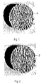
- the picture of the marks A and B placed on the locking labels will be obtained, by means of a video recorder.
- the digitized video pictures represent the video codes A and B. respectively, which will be stored in a computer. Any other characteristics of the given memori of goods can also be stored in the same storage area.
- the video picture and the video code of the mark placed on the blocking label will be prepared and compared in a known manner with the video code stored in the computer.
- Figs. 1 and 2 show the video pictures in a tenfold magnification. In our case, no deviations are visible to the naked eye. However, as stochastic processes take place during the electro-erosion, it is also possible that differences visible to the naked eye can be observed when repeating the operations described in this example.
- the print matrices in use will suffer some changes.
- the print matrice remains suitable for further use, with a new surface prepared by means of electro-erosion in place of the worn surface, represented by a new video code, or even, the old print matrice can be replaced by a new one, represented by a new video code.
- this is not considered a disadvantage; instead, it causes further difficulties to counterfeiters.
- a motor car component part will be marked in the manner described in the Example 1.
- a component part to be built-in and made in mass production or an accessible surface of some component part already built in a motor car in use can be used.
- the video code of the marking will be established and stored in a computer, together with other ID data of the motor car.
- Example 1 shows that the printing surfaces will not be the same even under the same conditions for producing the print matrices. Indeed, the probability of obtaining the same optic pictures for the surfaces both A and B will be 10 -19 or less. It is also proved that the markings printed on metal sheets can be identified by using simple video technique and by comparing their video codes by means of a computer.
- Example 2 The method described in the Example 2 is suitable to provide the surfaces on conductible, metallic parts of machines such as traffic means, military equipment and objects etc. with individual markings that are unable to be copied and counterfeited. Furthermore, it also enables the markings to be properly documented, thus making the objects marked suitable to be identified by using various methods even immediately if so required.
- the average roughness of the markings will be around 10 ⁇ m.
- the size of formations varies between 0.4 to 15 ⁇ m and can be controlled by the material of the part and/or the electrode and/or the dielectric. and/or the parameters of the electro-erosion equipment.
- the pulse width and/or pulse break below 50 ⁇ s, preferably between 10 and 50 ⁇ s, and/or by reducing the peak current below 6 A. preferably between 2 and 6 A.
- the lower limit size of formations can be reduced below 0.4 ⁇ m.
- the space requirement of the marking can also be reduced, which makes the detection by third persons more difficult. In such cases.
- the picture and/or the code cannot be produced any more by means of video technique operating in the frequency range of visible light; however, by using an ultraviolet camera and/or other mapping methods e.g. optical interferometer and/or autotrophic and/or parametric optic, this problem can be solved.
- the optic reader subassembly When the key is inserted into the lock, the optic reader subassembly reads the identifier marking established on the web of the key, while activating the unit of identification which, based on its own programmed algorithm, compares the pattern previously stored to the pattern read by the optic reader. If the two patterns are identical, that is, their digitized sequences coincide, the locking device will be opened, otherwise it remains locked.
- the markings of chaotic arrangement according to the present invention can also be produced by means of other physical or chemical procedures, e.g. by chemical corrosion and/or grinding.
- the marking included in the print matrice can be printed on various materials, such as paper, metal sheet, metal strip, plastic sheet; furthermore, the print can be protected against any counterfeit by covering it with some transparent material in a known manner if required.
- the quality of print matrice can be monitored on the basis of possible changes in the code of marking printed by that print matrice,
- the code of the marking printed last shows differences beyond the permissible tolerances as compared to the code of marking printed second last, this means that the print matrice became worn.
- the new code can be documented or the print matrice can be renewed or a new print matrice can be used. Worn print matrices can also be renewed by reprocessing the printing surface containing the marking e.g. by using electro-erosion.
Abstract
Description
The picture and/or the code of marking will be produced by using video record and/or autotrophic- and or parametric optics. The picture and/or the code of marking will be produced by using an optical interferometer.
- idle voltage: 60 to 100 V, preferably 80 V;
- peak current: 6 to 25 A:
- pulse width: 50 to 800 µs;
- break between pulses: 50 to 800 µs.
Claims (11)
- Method for the identification of an object based on forming and verifying its surface roughness, comprising the steps ofproducing a 3-dimensional marking on the object that makes its surface rough (A, B),obtaining recognition data of said produced 3 dimensional marking (A, B),storing the obtained recognition data of said three dimensional marking (A, B) in a storage means,comparing the recognition data of a marking on an object to said stored recognition data, characterized in thatthe elementary formations of the surface roughness of the 3-dimensional marking (A, B) are in a chaotic arrangement.
- Method for identification of an object according to claim 1, wherein said 3-dimensional marking (A, B) is established by means of a stochastic electro erosion process.
- Method for identification of an object according to claim 2, further comprising the step of setting adjustable process parameters of the stochastic electro erosion process as follows: idle voltage = 60 to 100 V, peak current = 6 to 25 A, pulse width = 50 to 800 µs, and break between pulses = 10 to 800 µs.
- Method for identification of an object according to claim 3 further comprising the step of
randomly controlling the adjustable process parameters by means of a random or quasi random generator. - Method for the identification of an object based on forming and verifying its surface roughness, comprising the steps ofproducing a 3-dimensional marking on the object that makes its surface rough (A, B),obtaining recognition data of said produced 3 dimensional marking (A, B),storing the obtained recognition data of said three dimensional marking (A, B) in a storage means,comparing the recognition data of a marking on an object to said stored recognition data, characterized in the step of establishing by means of a print matrice said three dimensional marking wherein the elementary formations of the surface roughness of the 3-dimensional marking (A, B) are in a chaotic arrangement
- Method for identification of an object according to claim 5, characterized in that said 3 dimensional marking (A, B) prepared on the print matrice will be printed if necessary on paper, metal sheet, metal strip or plastic sheet containing other items of information and the print will be covered by transparent material if necessary.
- Method for identification of an object acording to claims 1 to 6, chatacterized in that the code of said 3 dimensional marking (A, B) will be produced using video record or autotrophic or parametric optics.
- Method for identification of an object according to claims 1 to 7, characterized in that the code of said 3 dimensional marking (A, B) will be produced by using an optical interferometer.
- Method for identification of an object according to claims 4 or 5, characterized in that, if the difference between the code of said three dimensional marking (A, B) produced last by means of the print matrice and the code of previous marking (A, B) exceeds the applied tolerances the print matrice will be changed or the changes in the code documented.
- An object having a surface suitable for identification based on forming and verifying its surface roughness which has a three dimensional marking (A, B) on its optically accessible surface, which three dimensional marking (A, B) alters the surface roughness of the object and was produced by a physical and/or chemical process characterized in that the elementary formations of the the surface roughness of said three dimensional marking (A, B) are in a chaotic arrangement.
- Object as in claim 10, characterized in that the size of the elementary formations of surface roughness lies between 0.1 and 30 µm.
Applications Claiming Priority (3)
| Application Number | Priority Date | Filing Date | Title |
|---|---|---|---|
| HU9402179 | 1994-07-25 | ||
| HU9402179A HU211281B (en) | 1994-07-25 | 1994-07-25 | Method for identificating objects on the basis of the forming and checking their surface roughness, further an object having surface suitable to said identification |
| PCT/HU1995/000032 WO1996003714A1 (en) | 1994-07-25 | 1995-07-03 | Procedure for identification of objects based on forming and verifying their surface roughness as well as objects suitable to be identified |
Publications (2)
| Publication Number | Publication Date |
|---|---|
| EP0772843A1 EP0772843A1 (en) | 1997-05-14 |
| EP0772843B1 true EP0772843B1 (en) | 1999-05-19 |
Family
ID=10985455
Family Applications (1)
| Application Number | Title | Priority Date | Filing Date |
|---|---|---|---|
| EP95925082A Expired - Lifetime EP0772843B1 (en) | 1994-07-25 | 1995-07-03 | Procedure for identification of objects based on forming and verifying their surface roughness as well as objects suitable to be identified |
Country Status (7)
| Country | Link |
|---|---|
| US (1) | US20020126889A1 (en) |
| EP (1) | EP0772843B1 (en) |
| AT (1) | ATE180343T1 (en) |
| AU (1) | AU2934695A (en) |
| DE (1) | DE69509777T2 (en) |
| HU (1) | HU211281B (en) |
| WO (1) | WO1996003714A1 (en) |
Cited By (4)
| Publication number | Priority date | Publication date | Assignee | Title |
|---|---|---|---|---|
| US6542620B1 (en) | 1993-11-18 | 2003-04-01 | Digimarc Corporation | Signal processing to hide plural-bit information in image, video, and audio data |
| US6587821B1 (en) | 1993-11-18 | 2003-07-01 | Digimarc Corp | Methods for decoding watermark data from audio, and controlling audio devices in accordance therewith |
| US6754377B2 (en) | 1995-05-08 | 2004-06-22 | Digimarc Corporation | Methods and systems for marking printed documents |
| EP2009600A2 (en) | 2007-06-29 | 2008-12-31 | Siemens Healthcare Diagnostics Products GmbH | Method for identifying a transparent object based on its absorption spectrum |
Families Citing this family (39)
| Publication number | Priority date | Publication date | Assignee | Title |
|---|---|---|---|---|
| US6345104B1 (en) * | 1994-03-17 | 2002-02-05 | Digimarc Corporation | Digital watermarks and methods for security documents |
| US8505108B2 (en) | 1993-11-18 | 2013-08-06 | Digimarc Corporation | Authentication using a digital watermark |
| US20030105730A1 (en) * | 1999-05-19 | 2003-06-05 | Rhoads Geoffrey B. | Postal meters and systems employing watermarking |
| US20030130954A1 (en) * | 1998-07-31 | 2003-07-10 | Carr J. Scott | Postal applications including digital watermarks |
| US7164413B2 (en) * | 1999-05-19 | 2007-01-16 | Digimarc Corporation | Enhanced input peripheral |
| US6608919B1 (en) | 1999-11-10 | 2003-08-19 | Digimarc Corporation | Method and apparatus for encoding paper with information |
| DE19957390A1 (en) * | 1999-11-24 | 2001-06-07 | Andreas Kuntze | Individualization system for an object |
| EP1227426A1 (en) * | 2001-01-30 | 2002-07-31 | Ulrich AG | Method to provide a machine readable code on a tool |
| US7958359B2 (en) | 2001-04-30 | 2011-06-07 | Digimarc Corporation | Access control systems |
| US7502937B2 (en) * | 2001-04-30 | 2009-03-10 | Digimarc Corporation | Digital watermarking security systems |
| DE10155780A1 (en) * | 2001-11-14 | 2003-05-22 | Vision Tools Hard Und Software | Securing objects against counterfeiting and/or imitation involves inserting and/or attaching non-reproducible physical random pattern during manufacture for later detection and comparison |
| GB0225290D0 (en) * | 2002-10-30 | 2002-12-11 | Secretary Trade Ind Brit | Anti-counterfeiting apparatus and method |
| EP1828995A1 (en) * | 2004-12-17 | 2007-09-05 | Koninklijke Philips Electronics N.V. | Optical identifier comprising randomly oriented partial faces |
| WO2007046018A1 (en) * | 2005-10-17 | 2007-04-26 | Koninklijke Philips Electronics N.V. | Integrated physical unclonable function (puf) with combined sensor and display |
| WO2007087498A2 (en) | 2006-01-23 | 2007-08-02 | Digimarc Corporation | Methods, systems, and subcombinations useful with physical articles |
| US8224018B2 (en) | 2006-01-23 | 2012-07-17 | Digimarc Corporation | Sensing data from physical objects |
| WO2008128714A1 (en) | 2007-04-24 | 2008-10-30 | Sicpa Holding S.A. | Method of marking a document or item; method and device for identifying the marked document or item; use of circular polarizing particles |
| EP2637145B1 (en) | 2007-04-24 | 2022-01-12 | Sicpa Holding Sa | Method of marking and identifying a document or item having circular polarizing particles |
| WO2011077459A2 (en) * | 2009-12-23 | 2011-06-30 | Alexia Technologies Private Limited | A method of extracting naturally encrypted features from a natural surface of a product |
| PT2820592T (en) | 2012-03-01 | 2018-03-22 | Sys Tech Solutions Inc | Unique identification information from marked features |
| US20150169928A1 (en) | 2012-03-01 | 2015-06-18 | Sys-Tech Solutions, Inc. | Methods and a system for verifying the identity of a printed item |
| US20150379321A1 (en) | 2012-03-01 | 2015-12-31 | Sys-Tech Solutions, Inc. | Methods and a system for verifying the authenticity of a mark |
| EP3958241A1 (en) * | 2013-03-12 | 2022-02-23 | Arizona Board of Regents, a Body Corporate of the State of Arizona acting for and on behalf of Arizona State University | Dendritic structures and tags |
| WO2016073910A1 (en) | 2014-11-07 | 2016-05-12 | Arizona Board Of Regents On Behalf Of Arizona State University | Information coding in dendritic structures and tags |
| US9940572B2 (en) | 2015-02-17 | 2018-04-10 | Sys-Tech Solutions, Inc. | Methods and a computing device for determining whether a mark is genuine |
| US10235597B2 (en) | 2015-06-16 | 2019-03-19 | Sys-Tech Solutions, Inc. | Methods and a computing device for determining whether a mark is genuine |
| US10061958B2 (en) | 2016-03-14 | 2018-08-28 | Sys-Tech Solutions, Inc. | Methods and a computing device for determining whether a mark is genuine |
| US10703086B2 (en) | 2017-04-05 | 2020-07-07 | General Electric Company | System and method for authenticating an additively manufactured component |
| US10762407B2 (en) | 2017-04-05 | 2020-09-01 | General Electric Company | Component incorporating 3-D identification code |
| US10943240B2 (en) | 2017-04-05 | 2021-03-09 | General Electric Company | Additively manufactured component including a contrast agent for part identification |
| US10549347B2 (en) | 2017-04-05 | 2020-02-04 | General Electric Company | System and method for authenticating components |
| US10706139B2 (en) | 2017-04-05 | 2020-07-07 | General Electric Company | System and method for authenticating components |
| US11090727B2 (en) | 2017-04-05 | 2021-08-17 | General Electric Company | Additively manufactured component having surface features for part identification |
| US11430233B2 (en) | 2017-06-16 | 2022-08-30 | Arizona Board Of Regents On Behalf Of Arizona State University | Polarized scanning of dendritic identifiers |
| WO2019210129A1 (en) | 2018-04-26 | 2019-10-31 | Kozicki Michael N | Fabrication of dendritic structures and tags |
| PT111116B (en) | 2018-08-31 | 2023-02-28 | Univ De Coimbra | METHOD FOR INTENSIFYING THE SECURITY LEVEL OF AN OBJECT BY MEANS OF A DETERMINISTIC DESIGN, OBJECT WITH INTENSIFIED SECURITY LEVEL AND THE METHOD, COMPUTER APPLIANCE, COMPUTER PROGRAMS, READING MEDIA AND APPARATUS ADAPTED FOR PREPARING THE OBJECT |
| SG10202001721UA (en) | 2019-03-14 | 2020-10-29 | Gen Electric | Acoustic inspection device and method of operation |
| US11031346B2 (en) | 2019-05-15 | 2021-06-08 | International Business Machines Corporation | Advanced wafer security method including pattern and wafer verifications |
| US11420259B2 (en) | 2019-11-06 | 2022-08-23 | General Electric Company | Mated components and method and system therefore |
Family Cites Families (5)
| Publication number | Priority date | Publication date | Assignee | Title |
|---|---|---|---|---|
| BE837814A (en) * | 1976-01-22 | 1976-05-14 | ENGRAVING PROCESS | |
| US4441005A (en) * | 1980-05-06 | 1984-04-03 | Sodick Co., Ltd. | EDM Pulse generator with a variable output inductor for producing pulse with gradually rising edges |
| FR2601271B1 (en) * | 1986-07-10 | 1990-07-13 | Banque De France | PROCESS FOR MANUFACTURING A TOOL FOR THE STAMPING OF ROUND CANVAS OF A ROUND FORM USED FOR MAKING WATERCOLORS, AND APPARATUS FOR IMPLEMENTING THE PROCESS. |
| FR2624791B1 (en) * | 1987-12-21 | 1993-08-13 | Banque De France | PROCESS FOR THE SERIAL MANUFACTURE OF STEEL CUTTER PRINTING ELEMENTS, AND APPARATUS FOR CARRYING OUT SAID METHOD |
| FR2659760B1 (en) * | 1990-03-13 | 1993-01-22 | Arjomari Prioux | PROCESS FOR THE MANUFACTURE OF A PUNCHER FOR STAMPING, FOR EXAMPLE CANVAS FOR FORMING FILIGRANES AND DEVICE FOR CARRYING OUT SAID METHOD. |
-
1994
- 1994-07-25 HU HU9402179A patent/HU211281B/en not_active IP Right Cessation
-
1995
- 1995-07-03 US US08/765,979 patent/US20020126889A1/en not_active Abandoned
- 1995-07-03 AU AU29346/95A patent/AU2934695A/en not_active Abandoned
- 1995-07-03 AT AT95925082T patent/ATE180343T1/en not_active IP Right Cessation
- 1995-07-03 DE DE69509777T patent/DE69509777T2/en not_active Expired - Fee Related
- 1995-07-03 WO PCT/HU1995/000032 patent/WO1996003714A1/en active IP Right Grant
- 1995-07-03 EP EP95925082A patent/EP0772843B1/en not_active Expired - Lifetime
Cited By (7)
| Publication number | Priority date | Publication date | Assignee | Title |
|---|---|---|---|---|
| US6542620B1 (en) | 1993-11-18 | 2003-04-01 | Digimarc Corporation | Signal processing to hide plural-bit information in image, video, and audio data |
| US6587821B1 (en) | 1993-11-18 | 2003-07-01 | Digimarc Corp | Methods for decoding watermark data from audio, and controlling audio devices in accordance therewith |
| US6754377B2 (en) | 1995-05-08 | 2004-06-22 | Digimarc Corporation | Methods and systems for marking printed documents |
| EP2009600A2 (en) | 2007-06-29 | 2008-12-31 | Siemens Healthcare Diagnostics Products GmbH | Method for identifying a transparent object based on its absorption spectrum |
| DE102007030384A1 (en) | 2007-06-29 | 2009-01-02 | Dade Behring Marburg Gmbh | Method for identifying a transparent object based on its absorption spectrum |
| DE102007030384B4 (en) * | 2007-06-29 | 2009-02-05 | Dade Behring Marburg Gmbh | Method for identifying a transparent object based on its absorption spectrum |
| US8004671B2 (en) | 2007-06-29 | 2011-08-23 | Siemens Healthcare Diagnostics Products Gmbh | Method for identifying a transparent object with the aid of its absorption spectrum |
Also Published As
| Publication number | Publication date |
|---|---|
| AU2934695A (en) | 1996-02-22 |
| DE69509777D1 (en) | 1999-06-24 |
| HU211281B (en) | 1996-11-28 |
| HU9402179D0 (en) | 1994-09-28 |
| WO1996003714A1 (en) | 1996-02-08 |
| ATE180343T1 (en) | 1999-06-15 |
| US20020126889A1 (en) | 2002-09-12 |
| EP0772843A1 (en) | 1997-05-14 |
| DE69509777T2 (en) | 1999-12-16 |
Similar Documents
| Publication | Publication Date | Title |
|---|---|---|
| EP0772843B1 (en) | Procedure for identification of objects based on forming and verifying their surface roughness as well as objects suitable to be identified | |
| KR100189654B1 (en) | Magnetic metallic security thread with negative inscription | |
| EP0642933B1 (en) | Printed matter and printing method | |
| EP1297366B1 (en) | Optical structure | |
| US5975583A (en) | Carrier representing value and comprising patterns applied by a laser beam | |
| EP1294576B1 (en) | A security device | |
| US7835563B2 (en) | Method of guaranteeing the authenticity of documents by checking for the presence of a changed feature, and the document | |
| US20060197337A1 (en) | Identification document with lenticular watermark | |
| NO174999B (en) | Document with counterfeit-proof surface relief and method of making it | |
| EP1144201A1 (en) | Security document with a perforation pattern | |
| US4371196A (en) | Security filament as protection against fraud | |
| JP2006205674A (en) | Anticounterfeit medium | |
| US20230364935A1 (en) | Security devices and methods of manufacture thereof | |
| CN103729611A (en) | Image anti-counterfeiting recognition method applied to product packaging | |
| DE102005013962B4 (en) | Document paper with printed security element and method for creating forgery-proof documents | |
| EP3210794A1 (en) | Multi-layered polymeric article, such as an identification document | |
| US7925885B2 (en) | Method for recording and reading a code of material products for protection and control of their authenticity, and a system therefor | |
| EP0975467A1 (en) | Transitory image structure | |
| GB2191733A (en) | Security system for tickets or labels | |
| RU2204863C1 (en) | Method for protecting documents, including securities, and for authenticating them | |
| US20070202348A1 (en) | Method For The Production Of A Stamping Tool To Stamp Safety Elements In Surfaces Of Carrier Materials, As Well As Carrier Material With At Least One Safety Element | |
| GB2283455A (en) | Authenticating articles | |
| RU2399496C2 (en) | Electric discharge method of making strictly accountable paper documents and paper money | |
| GB2372232A (en) | Security card with luminescent material | |
| DE102021115558A1 (en) | Procedure for determining the originality and typing of a product |
Legal Events
| Date | Code | Title | Description |
|---|---|---|---|
| PUAI | Public reference made under article 153(3) epc to a published international application that has entered the european phase |
Free format text: ORIGINAL CODE: 0009012 |
|
| 17P | Request for examination filed |
Effective date: 19970224 |
|
| AK | Designated contracting states |
Kind code of ref document: A1 Designated state(s): AT CH DE ES FR GB IT LI NL SE |
|
| AX | Request for extension of the european patent |
Free format text: LT PAYMENT 970224;LV PAYMENT 970224;SI PAYMENT 970224 |
|
| 17Q | First examination report despatched |
Effective date: 19970912 |
|
| GRAG | Despatch of communication of intention to grant |
Free format text: ORIGINAL CODE: EPIDOS AGRA |
|
| GRAG | Despatch of communication of intention to grant |
Free format text: ORIGINAL CODE: EPIDOS AGRA |
|
| GRAG | Despatch of communication of intention to grant |
Free format text: ORIGINAL CODE: EPIDOS AGRA |
|
| GRAH | Despatch of communication of intention to grant a patent |
Free format text: ORIGINAL CODE: EPIDOS IGRA |
|
| GRAH | Despatch of communication of intention to grant a patent |
Free format text: ORIGINAL CODE: EPIDOS IGRA |
|
| GRAA | (expected) grant |
Free format text: ORIGINAL CODE: 0009210 |
|
| DAX | Request for extension of the european patent (deleted) | ||
| RBV | Designated contracting states (corrected) |
Designated state(s): AT CH DE ES FR GB IT LI NL SE |
|
| AK | Designated contracting states |
Kind code of ref document: B1 Designated state(s): AT CH DE ES FR GB IT LI NL SE |
|
| PG25 | Lapsed in a contracting state [announced via postgrant information from national office to epo] |
Ref country code: SE Free format text: THE PATENT HAS BEEN ANNULLED BY A DECISION OF A NATIONAL AUTHORITY Effective date: 19990519 Ref country code: NL Free format text: LAPSE BECAUSE OF FAILURE TO SUBMIT A TRANSLATION OF THE DESCRIPTION OR TO PAY THE FEE WITHIN THE PRESCRIBED TIME-LIMIT Effective date: 19990519 Ref country code: IT Free format text: LAPSE BECAUSE OF FAILURE TO SUBMIT A TRANSLATION OF THE DESCRIPTION OR TO PAY THE FEE WITHIN THE PRE;WARNING: LAPSES OF ITALIAN PATENTS WITH EFFECTIVE DATE BEFORE 2007 MAY HAVE OCCURRED AT ANY TIME BEFORE 2007. THE CORRECT EFFECTIVE DATE MAY BE DIFFERENT FROM THE ONE RECORDED.SCRIBED TIME-LIMIT Effective date: 19990519 Ref country code: FR Free format text: LAPSE BECAUSE OF FAILURE TO SUBMIT A TRANSLATION OF THE DESCRIPTION OR TO PAY THE FEE WITHIN THE PRESCRIBED TIME-LIMIT Effective date: 19990519 Ref country code: ES Free format text: THE PATENT HAS BEEN ANNULLED BY A DECISION OF A NATIONAL AUTHORITY Effective date: 19990519 |
|
| REF | Corresponds to: |
Ref document number: 180343 Country of ref document: AT Date of ref document: 19990615 Kind code of ref document: T |
|
| REG | Reference to a national code |
Ref country code: CH Ref legal event code: EP |
|
| REF | Corresponds to: |
Ref document number: 69509777 Country of ref document: DE Date of ref document: 19990624 |
|
| PGFP | Annual fee paid to national office [announced via postgrant information from national office to epo] |
Ref country code: FR Payment date: 19990707 Year of fee payment: 5 |
|
| EN | Fr: translation not filed | ||
| RBV | Designated contracting states (corrected) |
Designated state(s): AT CH DE ES FR GB IT LI NL SE |
|
| PLBE | No opposition filed within time limit |
Free format text: ORIGINAL CODE: 0009261 |
|
| STAA | Information on the status of an ep patent application or granted ep patent |
Free format text: STATUS: NO OPPOSITION FILED WITHIN TIME LIMIT |
|
| 26N | No opposition filed | ||
| REG | Reference to a national code |
Ref country code: GB Ref legal event code: IF02 |
|
| PGFP | Annual fee paid to national office [announced via postgrant information from national office to epo] |
Ref country code: AT Payment date: 20020809 Year of fee payment: 8 |
|
| PGFP | Annual fee paid to national office [announced via postgrant information from national office to epo] |
Ref country code: GB Payment date: 20020815 Year of fee payment: 8 |
|
| PG25 | Lapsed in a contracting state [announced via postgrant information from national office to epo] |
Ref country code: GB Free format text: LAPSE BECAUSE OF NON-PAYMENT OF DUE FEES Effective date: 20030703 Ref country code: AT Free format text: LAPSE BECAUSE OF NON-PAYMENT OF DUE FEES Effective date: 20030703 |
|
| GBPC | Gb: european patent ceased through non-payment of renewal fee |
Effective date: 20030703 |
|
| PGFP | Annual fee paid to national office [announced via postgrant information from national office to epo] |
Ref country code: DE Payment date: 20050927 Year of fee payment: 11 |
|
| PG25 | Lapsed in a contracting state [announced via postgrant information from national office to epo] |
Ref country code: DE Free format text: LAPSE BECAUSE OF NON-PAYMENT OF DUE FEES Effective date: 20070201 |
|
| REG | Reference to a national code |
Ref country code: CH Ref legal event code: PL |
|
| PG25 | Lapsed in a contracting state [announced via postgrant information from national office to epo] |
Ref country code: CH Free format text: LAPSE BECAUSE OF NON-PAYMENT OF DUE FEES Effective date: 20110731 Ref country code: LI Free format text: LAPSE BECAUSE OF NON-PAYMENT OF DUE FEES Effective date: 20110731 |
|
| REG | Reference to a national code |
Ref country code: CH Ref legal event code: NV Representative=s name: MICHELI & CIE SA Ref country code: CH Ref legal event code: AEN Free format text: DAS PATENT IST AUFGRUND DES WEITERBEHANDLUNGSANTRAGS VOM 30.04.2012 REAKTIVIERT WORDEN. |
|
| PGRI | Patent reinstated in contracting state [announced from national office to epo] |
Ref country code: LI Effective date: 20120503 Ref country code: CH Effective date: 20120503 |
|
| REG | Reference to a national code |
Ref country code: CH Ref legal event code: PL Ref country code: CH Ref legal event code: AECN Free format text: DAS PATENT IST AUFGRUND DES WEITERBEHANDLUNGSANTRAGS VOM 06.02.2013 REAKTIVIERT WORDEN. |
|
| PGFP | Annual fee paid to national office [announced via postgrant information from national office to epo] |
Ref country code: CH Payment date: 20130220 Year of fee payment: 18 |
|
| REG | Reference to a national code |
Ref country code: CH Ref legal event code: PL |
|
| PG25 | Lapsed in a contracting state [announced via postgrant information from national office to epo] |
Ref country code: CH Free format text: LAPSE BECAUSE OF NON-PAYMENT OF DUE FEES Effective date: 20130731 Ref country code: LI Free format text: LAPSE BECAUSE OF NON-PAYMENT OF DUE FEES Effective date: 20130731 |