EP0772318A2 - Filtering system and method for high performance network management map - Google Patents
Filtering system and method for high performance network management map Download PDFInfo
- Publication number
- EP0772318A2 EP0772318A2 EP96116263A EP96116263A EP0772318A2 EP 0772318 A2 EP0772318 A2 EP 0772318A2 EP 96116263 A EP96116263 A EP 96116263A EP 96116263 A EP96116263 A EP 96116263A EP 0772318 A2 EP0772318 A2 EP 0772318A2
- Authority
- EP
- European Patent Office
- Prior art keywords
- block
- network
- objects
- discovery
- transfers
- Prior art date
- Legal status (The legal status is an assumption and is not a legal conclusion. Google has not performed a legal analysis and makes no representation as to the accuracy of the status listed.)
- Granted
Links
Images


Classifications
-
- H—ELECTRICITY
- H04—ELECTRIC COMMUNICATION TECHNIQUE
- H04L—TRANSMISSION OF DIGITAL INFORMATION, e.g. TELEGRAPHIC COMMUNICATION
- H04L41/00—Arrangements for maintenance, administration or management of data switching networks, e.g. of packet switching networks
- H04L41/02—Standardisation; Integration
- H04L41/0213—Standardised network management protocols, e.g. simple network management protocol [SNMP]
-
- H—ELECTRICITY
- H04—ELECTRIC COMMUNICATION TECHNIQUE
- H04L—TRANSMISSION OF DIGITAL INFORMATION, e.g. TELEGRAPHIC COMMUNICATION
- H04L41/00—Arrangements for maintenance, administration or management of data switching networks, e.g. of packet switching networks
- H04L41/12—Discovery or management of network topologies
-
- H—ELECTRICITY
- H04—ELECTRIC COMMUNICATION TECHNIQUE
- H04L—TRANSMISSION OF DIGITAL INFORMATION, e.g. TELEGRAPHIC COMMUNICATION
- H04L41/00—Arrangements for maintenance, administration or management of data switching networks, e.g. of packet switching networks
- H04L41/22—Arrangements for maintenance, administration or management of data switching networks, e.g. of packet switching networks comprising specially adapted graphical user interfaces [GUI]
Definitions
- the present invention generally relates to data communication networks and, more particularly, to a filtering system and method for permitting high performance generation of a network management trap of a data communication network in a management station.
- a data communications network generally includes a group of devices, for instance, computers, repeaters, bridges, routers, etc., situated at network nodes and a collection of communication channels for interconnecting the various nodes. Hardware and software associated with the network and particularly the devices permit the devices to exchange data electronically via the communication channels.
- a local area network is a network of devices in close proximity, typically less than one mile, and usually connected by a single cable, for instance, a coaxial cable.
- a wide area network is a network of devices which are separated by longer distances, often connected by, for example, telephone lines or satellite links. In fact, some WANs span the U.S. as well as the world. Furthermore, many of these networks are widely available for use by the public, including commonly universities and commercial industries.
- IP Internet Protocol
- TCP Transmission Control Protocol
- UDP Unreliable Datagram Protocol
- TCP/IP Transmission Control Protocol/IP
- SNMP Simple Network Management Protocol
- Some management stations have on-demand submap capabilities.
- One such example is Hewlett-Packard's "OPENVIEW”TM.
- OPENVIEW a submap corresponds with each view of the network to be displayed.
- the network management map is the collection of all submaps.
- the user specifies which submaps the user wishes to have available, and hence, specifies the submaps which are resident within the map.
- the user can also open, or "explode,” a submap during operation even though it is not specified as resident in the map.
- the submap is generated immediately from the topology data when the user prompts the manager station to open the submap, hence the name on-demand.
- the present invention is a filtering system and method for a management station for customizing the contents of a network management map.
- the system comprises a processor which executes the instructions provided by the various software elements of the system, a memory for storing the various software elements, a display for showing the devices and interconnections of the network, an interface that interconnects the foregoing elements and the network, a discovery mechanism for determining the network topology data, a layout mechanism for converting the network topology data to map data and for driving the display with the map data, and a filtering system, which is a significant feature of the present invention as will be further described immediately hereafter.
- the filtering system can be situated in one or more of three possible locations in the management station. First, the filtering system can be situated between the discovery mechanism and the layout mechanism so that the filtering system filters objects within the topology data that pass from the discovery mechanism to the layout mechanism. Second, the filtering system can also be situated between the layout mechanism and the network so that the filtering system filters objects within the topology data that pass from the network to the discovery mechanism. Third, the filtering system can also be situated between discovery mechanisms so that the filtering system filters objects within the topology data that passes between the discovery mechanisms.
- the filtering systems utilize a common filtering library, which contains the filtering specification pertaining to the objects.
- the filtering specification associated with each filtering system can include a list of one or more objects to be allowed or disallowed, a boolean expression (or equation) defining which objects are to be allowed or disallowed, or any other mechanism for specifying a filtering condition.
- the filtering system and method of the present invention has numerous other advantages, a few of which are delineated hereafter, as examples.
- Another advantage of the filtering system and method is that they customize the contents of a network management map generated by a management station so as to reduce clutter of objects in submaps.
- Another advantage of the filtering system and method is that they minimize memory requirements as well as resultant expense for generating a network management map in a management station.
- Another advantage of the filtering system and method is that they enhance the performance of a process for generating a network management map in a management station.
- Another advantage of the filtering system and method is that they minimize requisite processing time for producing a network management map in a management station.
- Another advantage of the filtering system and method is that they minimize requisite interprocess communication in a management station for generating a network management map of a data communications network.
- Another advantage of the filtering system and method is that they are simple in design and easy to implement.
- Another advantage of the filtering system and method is that they are efficient as well as reliable in operation.
- the filtering system of the present invention can be stored on any computer-readable medium for use by or in connection with a computer-related system or method.
- a computer-readable medium is an electronic, magnetic, optical, or other physical device or means that can contain or store a computer program for use by or in connection with a computer-related system or method.
- the novel filtering system can be stored and transported on a portable diskette, or as another example, the filtering system could be stored in the memory of a computer for the purpose of driving the computer when called upon.
- Fig. 1 shows a block diagram of an object-oriented management station 100 which is implemented with a general purpose computer system containing discovery/layout software 101, which employs the filtering system and associated methodology of the present invention.
- the novel filtering system is designated by reference numeral 103 in Fig. 1.
- the management station 100 contains a conventional processor 102.
- the processor 102 communicates to other elements within the management station 100 over an interface 104, such as a bus or bus network.
- An input device 106 for example, a keyboard or mouse, is used to input data from a user of the management station 100, and a display 108 is used to output data to the user.
- a network interface 112 is used to interface the management station 100 to a network 118 in order to allow the management station 100 to act as a node on a network 118.
- a memory 110 within the management station 100 contains discovery/layout software 101.
- the discovery/layout software 101 communicates with a conventional operating system 122 and conventional network software 124 to discover the nodes on the network 118.
- the network software 124 serves as the intelligence, including validation, for the data communication protocols. As shown in Fig. 1, in the preferred embodiment, the network software implements the IP, the TCP and UDP over the IP, and the SNMP over the UDP. All of the foregoing protocols are well known in the art.
- the discovery/layout software 101 implements object-oriented functionality.
- object-oriented means that most of the management system actions and processes that the user can invoke are oriented toward a class of devices rather than individually managed network nodes.
- the discovery/layout software 101 of Fig. 1 is configured to discover the network topology, that is, network nodes and node interconnections existing on the network 118, and to construct a network management map comprising various submaps, any of which can be used for displaying the network topology on the display 108.
- Fig. 2 shows a network management map 200 which is generated by the discovery/layout software 101 from topology data discovered from the network 118.
- the discovery/layout software 101 can drive any of the various submaps to the display 108 (Fig. 1) for viewing by the user.
- a root submap 202 is defined at a root level.
- the root submap 202 represents the highest logical level submap in the hierarchy and shows objects 203 acting as anchor points for different submap hierarchies.
- Each hierarchy is a separate management domain. This could be, for instance, a network, logical grouping of nodes, or some other domain.
- An internet submap 204 is defined at an internet level and is generated by "exploding" an object 203 within the root submap 202. "Exploding" in the context of this document means that the user prompts the management station 100 with the input device 106 to break down and provide more data pertaining to the object 203 at issue.
- the internet submap 204 illustrates objects 203 in the form of networks and routers. Any one of a number of network submaps 206 can be exploded from the internet submap 204. Each network submap 206 shows objects 203 in the form of segments and connectors. Any one of a number of segment submaps 208 can be exploded from an object 203 within a network submap 206. Each segment submap 208 shows objects in the form of network nodes. Finally, any one of a number of node submaps 210 can be exploded from an object 203 within a segment submap 208. Each node submap 210 shows objects 203 in the form of interfaces within that node.
- the discovery/layout software 101 implements on-demand submaps in order to save memory and processing time.
- the concept of on-demand submaps is to only place those submaps in the map 200 of Fig. 2 which the user wants to see.
- the net result is that only a portion of the submap hierarchy is in the network management map 200 at a given time.
- submaps (nonresident) which are not present, but would be created upon prompting by the user, are indicated by hatching.
- the resident submap subset of the hierarchy will change over time as the user traverses the submap hierarchy and causes nonresident submaps to be created.
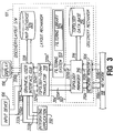
- FIG. 3 A high level block diagram of a first embodiment of the discovery/layout software 101 (Fig. 1) is set forth in Fig. 3. With the exception of the filtering system 103, the architecture of the discovery/layout software 101 in Fig. 3 is essentially the same as or similar to the architecture of Hewlett-Packard Company's well known and commercially available management software package called "OPENVIEW.”TM
- the discovery/layout software 101 comprises a discovery mechanism 302 for discovering nodes and interconnections of the network 118 and a layout mechanism 304 for receiving topology data from the discovery mechanism 302 and for generating the map 200 (Fig. 2) for driving the display 108.
- one or more integrating applications 332 may communicate display and map information with the layout mechanism 304.
- the discovery mechanism 302 has a network monitor 306 connected to the network 118 as indicated by connections 308a, 308b, a topology manager 310 connected to the network monitor 306 as indicated by arrows 312a, 312b, and a topology data base 314 in communication with the topology manager 310 as indicated by arrow 316.
- the network monitor 306 transmits and receives data packets to and from the network 118.
- the network monitor 306 discovers and monitors network topology, as indicated by arrows 308a, 308b.
- the network monitor 306 When network topology changes on the network, the network monitor 306 generates events, or traps (SNMP vernacular), which include an object identifier and object change information.
- the network monitor 306 can also receive events from other devices, such as a router, in the network 118.
- the network monitor 306 interacts with the network 118 by way of the network software 124 (Fig. 1), which essentially comprises protocol stacks, corresponding to IP, TCP, UDP, and SNMP in the preferred embodiment, and which generally implements these protocols and performs validation functions.
- the network monitor 306 populates the topology data base 314 by way of the topology manager 310 and notifies the topology manager 310 of events (topology changes).
- U.S. Patent No. 5,185,860 to Wu which is incorporated herein by reference, describes a node discovery system which could be employed to implement the network monitor 306 herein.
- the topology manager 310 manages the topology data base 314, as indicated by bidirectional arrow 316.
- the topology manager 310 prompts the network monitor 306 to update topology data related to particular events, as indicated by arrow 312a, and receives topology updates, as indicated by arrow 312b.
- the topology data base 314 stores topology data based upon objects, which are used to partition the network for logical reasons.
- Objects include, for example but not limited to, a network, a segment, a computer, a router, a repeater, a bridge, etc.
- the topology data stored with respect to the objects includes, for example but not limited to, an interface or device address, an interface or device type, an interface or device manufacturer, and whether an interface or device supports the SNMP.
- the filtering system 103 receives topology data from the topology manager 310 as indicated by arrow 320b', filters the topology data, and passes the processed data to the layout mechanism 304, as shown by arrow 320b''.
- the filtering system 103 maintains a filtering library 321, which specifies which objects within the topology data are to be communicated from the discovery mechanism 302 to the layout mechanism 304.
- the library determines whether objects are allowable objects or nonallowable objects.
- allowable objects are ultimately converted into map data and displayed, whereas nonallowable objects are not converted into map data and are not displayed.
- the filtering library contains a listing of filter names that are organized in three groups, namely, sets, filters, and filter expressions, which are described briefly hereafter.
- a set is simply a list of strings. The only operation available on sets is the test for membership (which can be prefaced with the boolean NOT operator). Set members may be enumerated in the filter file itself, or may be listed in a separate file. Any set member beginning with a slash (/) is assumed to be the name of a file where set members are listed, one per line. Files in number strings can be mixed in the same set definition.
- Filters are boolean expressions of database fields and values. Any suitable set of boolean expressions can be utilized within the filters.
- the operands that are combined by the aforementioned boolean operators are either a field name or a literal value to which database field values are compared.
- a filter expression allows multiple filters to be applied to a set of objects without requiring a new filter which is just the logical combination of others.
- the only valid operands in a filter expression are filters previously defined in the same filter file.
- any suitable set of boolean expressions can be utilized within the filter expressions.
- the boolean operators that are used in the filter expressions are different than those that are used in the filters.
- the following boolean expressions are utilized in the filter expressions: "
- these groups represent three different ways for a user to specify the filtering specification, the way depending upon the type of object to be filtered.
- the language for the filtering library 321 in the preferred embodiment is set forth hereafter in Table A.
- the listing in Table A is referred to herein as the filter definition file grammar, and it is maintained in the memory 110 (Fig. 1).
- the filters are divided into three groups, namely, sets, filters, and filter expressions.
- CriticalNodes for instance, are specified as the node “ov1" and a file “/var/openview/critical.nodes,” and therefore, the foregoing nodes are allowable and will be communicated by the filtering system 103.
- the filter expression "Connectors,” for instance, is allowable when the filter expression "Router && Level2Conn” is true, i . e ., when both Router and Level2Conn are true, or allowable.
- the layout mechanism 304 has a topology-to-map translator 318 in communication with the filtering system 103 as indicated by unidirectional arrow 320b'' and the topology manager 310 as indicated by unidirectional arrow 320a, a graphical user interface (GUI) 322 in communication with the topology-to-map translator 318 as indicated by arrows 324a, 324b, and a map data base 326 in communication with the GUI 322 as indicated by bidirectional arrow 328.
- the integrating application 332 communicates information with the GUI 322, as indicated by arrows 333a, 333b.
- a "context switch” as used herein refers to a change in control of the system 122 and/or processor 102 by the foregoing software elements.
- the translator 318 converts topology data from the topology data base 314 to map data and constructs the various submaps 202-210 in the network management map 200 of Fig. 2.
- the translator 318 can forward a request to the topology manager 310, as indicated by arrow 320a, in order to obtain topology data regarding particular objects.
- the topology manager 310 advises the translator 318, by way of filtering system 103 as indicated by the arrows 320b', 320b'', when topology data has changed based upon an event so that the translator 318 can make any appropriate changes in the submaps.
- the GUI 322 manages the map data base 326, as indicated by the bidirectional arrow 328, and manages the display 108 and input device 106, as indicated by the arrows 330a, 330b.
- the GUI 322 receives map updates from the translator 318, as indicated by arrow 324b, and submits user-triggered events to the translator 318, as indicated by arrow 324a.
- a user-triggered event includes a prompt 330a from a user to explode an object, as described relative to Fig. 2.
- FIG. 4 A high level block diagram of a second embodiment of the discovery/layout software 101 (Fig. 1) is set forth in Fig. 4.
- the second embodiment is constructed similar to the first embodiment (Fig. 3), and the previous discussion of similarly identified elements is incorporated herein by reference.
- both the discovery mechanism 302 and the layout mechanism 304 of the first and second embodiments of the discovery/layout software 101 are generally identical.
- the filtering system 103 in the second embodiment is situated between the discovery mechanism 302 and the network 118 so that the filtering system 103 filters objects that pass from the network 118 to the discovery mechanism 302. With this configuration, the filtering system 103 prevents nonallowable objects from even being stored in the topology data base 314.
- FIG. 5 A high level block diagram of a third embodiment of the discovery/layout software 101 (Fig. 1) is shown in Fig. 5.
- the third embodiment of Fig. 5 is constructed similar to the first and second embodiments (Figs. 3 and 4), and the previous discussion of similarly identified elements is incorporated herein by reference.
- the layout mechanism 304 of the third embodiment is identical to that of the first and second embodiments.
- a significant difference between the third embodiment and the first and second embodiments is the fact that the third embodiment utilizes a plurality of discovery mechanisms 302 (only two are shown in Fig. 6 for simplicity, but more are possible).
- the discovery mechanisms 302 generally function in parallel to discover devices and interconnections on the network 118.
- the topology from each discovery mechanism 302 is merged to a single particular topology manager 310 where it is then communicated to the topology-to-map translator 318, as indicated by reference arrow 320b in Fig. 5.
- requests for topology data are passed from the translator 318 to the particular topology manager 310, which then retrieves the information.
- the discovery mechanisms 302 can transfer topology data between their respective topology managers 310 by way of a filtering system 103, as indicated by arrows 501a, 501b, 502a, 502b.
- the filtering system 103 as used in this context prevents transfer of nonallowable objects from one of the discovery mechanisms 302 to the other, while permitting transfer of allowable objects. Further, whether an object is allowable or nonallowable is defined by the filtering library 321, as previously discussed.
- FIG. 6 A high level block diagram of a fourth embodiment of the discovery/layout software 101 (Fig. 1) is set forth in Fig. 6.
- the fourth embodiment comprises a hybrid of the features associated with the first, second, and third embodiments.
- the fourth embodiment includes at least two discovery mechanisms 302 (only two are shown in Fig. 6 for simplicity, but more are possible).
- the fourth embodiment includes a plurality of filtering systems 103, all utilizing a common filtering library 321, as indicated by reference arrow 602.
- a first filtering system 103 is situated between the discovery mechanisms 302 and the layout mechanism 304, as indicated by arrows 320b', 320b''. For simplicity, only the filter data flow is illustrated in Fig. 6. The aforementioned placement of the filtering system 103 is similar to that which was described relative to the first embodiment.
- a second filtering system 103 is situated between each of the discovery mechanisms 302 and the network 118, as indicated by arrows 308b', 308b'' in order to filter objects within topology data received from the network 118.
- This filtering system configuration is similar to that which was described previously relative to the second embodiment of the discovery/layout software 101.
- a third filtering system 103 is situated between the discovery mechanisms 302, as indicated by arrows 501, 502 in order to filter objects within topology data that is transferred from one discovery mechanism 302 to another discovery mechanism 302.
- This filtering system configuration is similar to that which was described in the third embodiment of the discovery/layout software 101.
- any combination of the filtering system placements described previously in the first, second, and third embodiments can be utilized and significantly, the filtering systems 103 can share the same filtering library 321. Because a common filtering library 321 is utilized, the individual components are freed from understanding the implementation and configuration of the filtering architecture. Moreover, the common filtering library 321 offers a consistent filtering system to the user. If each component were left to implement its own mechanism, each component would likely look different from each other to the user.
- the filtering system 103 with library 321 employs the same methodology and architecture for the first through fourth embodiments of the discovery/layout software 101 (Fig. 1). Accordingly, for purposes of simplicity, the filtering system 103 will be described in connection with the first embodiment of the discovery/layout software 101, as is illustrated in Fig. 3.
- the filtering system 103 is implemented as a part of the topology-to-map translator 318 (Fig. 3).
- Fig. 7 shows a flow chart 700 indicating the architecture and functionality of the preferred embodiment of the topology-to-map translator 318.
- the filtering system 103 is initialized, i . e ., the filters within the library 321 are initialized, as will be further described with reference to Fig. 8.
- other general initialization procedures are performed, as indicated in block 704.
- the general initialization procedures include establishing contact with the topology manager 310, establishing contact with the GUI 322, and reading map configuration data.
- Block 704 transfers to block 706.
- the map is updated with the changes that have occurred in the topology data. This procedure is further delineated in Fig. 9 and will be described hereinafter in detail.
- block 706 transfers to block 708.
- asynchronous events are handled, which are further delineated in Fig. 10.
- Fig. 8 shows a flow chart which illustrates the architecture and functionality of the initialize filters block 702 (Fig. 7).
- this software module the filters that the user has configured for the network management map 200 that is presently open are identified, and a determination is made as to whether the filters reside in the filtering library 321.
- the filter definition file grammar of Table A is read from the memory 110 (Fig. 1).
- the syntax of the filter definition file grammar is checked for errors.
- the contents of this file should follow the grammar outlined in Table A.
- Any suitable parsing mechanism can be utilized for parsing the filter definition file grammar during the syntax checking procedure.
- the LEX and YACC tools of the "UNIX"TM operating system are utilized for parsing the fields of the filter definition file grammar.
- the LEX and YACC tools, the "UNIX"TM operating system, and the concept behind operation of these programs are all well known in the art and, further, these programs are commercially available.
- the syntax is incorrect, then an error message is displayed over the display 108 (Fig. 1), as is indicated in the block 806 and the operation of the translator 318 is terminated.
- the block 804 transfers to the block 808.
- Block 808 transfers to a loop, which determines which filter names should be associated with the map at issue.
- the loop commences with block 810, where a counter CTR for filter names is initialized.
- a filter name is selected from the list and processed by the loop.
- it is determined whether the filter name from the list, denoted FILTERNAMELIST[CTR] where CTR number, is in the filter definition file grammar. If the filter name FILTERNAMELIST[CTR] is not in the filter definition file grammar, then an error message is displayed over the display 108, as indicated in the block 806 and the translator 318 terminates operation. If the filter name FILTERNAMELIST[CTR] is in the filter definition file grammar, then the filter name FILTERNAMELIST[CTR] is saved for future processing, as indicated in block 814.
- Block 814 transfers to block 816, where the counter CTR is incremented.
- block 818 a determination is made as to whether the counter CTR is greater than the total number of filter names. If not, then the block 818 transfers back to block 812 and the loop continues. If so, then the block 818 transfers to block 704 (Fig. 7).
- Fig. 9 illustrates a flow chart that describes the architecture and functionality of the update map block 706 (Fig. 7), wherein the map data residing within the map data base 326 is updated based upon the filtered topology data.
- a list of the one or more networks is retrieved by the translator 318 from the topology manager 310, which in turn obtains the list from the topology data base 314.
- Block 902 transfers to a loop that commences with block 904 and that processes and filters the objects in each network.
- a counter NETCTR is initialized.
- a determination is made as to whether the particular network NETWORK[NETCTR], where NETCTR number, passes the filters (prescribed by the filter names) pertaining to the map 200 that is open. This procedure will be further described later with reference to Fig. 13. If it is determined that the current network NETWORK[NETCTR] does not pass through the filters, then the counter NETCTR is incremented, as indicated in the block 908. Further, a determination is made as to whether the counter NETCTR has surpassed the total number of networks in the open map 200, as indicated in the block 910.
- the block 910 transfers back to the block 906 and the loop continues. To the contrary, if the counter NETCTR has exceeded the total number of networks, then the block 910 transfers back to the block 708 (Fig. 7).
- block 906 transfers to block 909.
- the translator 318 obtains a list of objects within NETWORK[NETCTR] from the topology manager 310 (and ultimately from the topology data base 314).
- the block 909 transfers to a loop, which processes each object in the list to determine which objects pass the filters.
- block 909 transfers to block 911, where a counter OBJCTR is initialized.
- a determination is made as to whether the current object, OBJ[OBJCTR] where OBJCTR number, passes the filters, as indicated in the block 912. This determination will be further described with reference to Fig. 13 hereinafter. If it is determined that the current object OBJ[OBJCTR] does not pass the filters, then the counter OBJCTR is incremented, as indicated in the flow chart block 914. Moreover, a determination is made as to whether the counter OBJCTR has exceeded the total number of objects. If not, then the block 916 transfers back to block 912 and the loop continues and processes the next object. If so, then the block 916 transfers to the block 908 (which causes selection of another network, if any are available).
- the block 912 transfers to the block 918.
- the translator 318 adds the current object to the map 200. This procedure is further delineated in Fig. 16, which will be described later in this document. After the object has been added to the map, the counter OBJCTR is incremented, and another object is processed, if available, as indicated in flow chart blocks 914, 916.
- Fig. 10 shows a flow chart pertaining to the handling of asynchronous events, as indicated in the block 708 of Fig. 7.
- the network monitor 306 When network topology changes on the network, the network monitor 306 generates events, or traps (SNMP vernacular), which include an object identifier and object change information.
- the network monitor 306 can also receive events from other devices, such as a router, in the network 118.
- events are queued and accumulated in a queue (not shown) or accumulator, associated with a topology manager 310, and await retrieval by the translator 318.
- the translator 318 reads a batch of events from the topology manager 310 during each access.
- the translator 318 calls the topology manager 310 for a list of topology data regarding all objects which were identified in the events. After receiving the topology data, block 1004 transfers to block 1006.
- the translator 318 computes the changes to be made to the map data, particularly the network management map 200 (Fig. 2), based upon the topology data changes indicated in the events. Block 1006 transfers to block 1008.
- the translator 318 updates the map 200 (Fig. 2) by calling the GUI 322 and advising the GUI 322 of all submap changes (SYMCHANGELIST and NEWSYMLIST described hereinafter) pertaining to all object changes.
- This transaction is preferably, although not necessarily, a batch transfer. During this batch transfer transaction, the translator 318 identifies each submap to be changed, each object to be changed within a submap, and the particular change to be effectuated to the object.
- An object change may include, for example, but not limited to, a color, position, or connection change.
- Block 1008 transfers to block 1010.
- the translator 318 determines whether there is another batch of events to be read from the topology manager 310. If so, then block 1010 transfers to block 1002 and the previously described process is repeated. If not, then the software waits at block 1010 for another batch of events.
- Fig. 11 sets forth a flow chart indicating the architecture and functionality of the read events block 1002 (Fig. 10).
- This flow chart illustrates how the translator 318 reads a batch of events from the topology manager 310.
- events from the topology manager 310 are accumulated (queued).
- a counter TRAPCTR at block 1104 is used in connection with a loop in order to route each event from the topology manager 310 to the translator 318.
- an event is read by the translator 318 from the topology manager 310.
- Block 1106 transfers to block 1108, which decodes the event.
- the event is decoded to identify the type of event and associated data. There are numerous types of events, and different types of events will have different types of associated data.
- an event can involve, for example, but not limited to, a new node or a node status change (e . g ., connected/accessible or connected/unaccessible).
- An event has an event identifier, usually at the header, for identifying the type of event.
- the event will contain an object identifier and an address.
- the event will contain an object identifier, the old status, and the new status.
- Block 1108 transfers to block 1110.
- the decoded event data i . e ., a record
- the counter TRAPCTR is incremented so that another event is serviced.
- Block 1112 transfers to block 1114, which determines whether there are any more events to be serviced. If so, then block 1114 transfers back to block 1106 and the aforementioned process is repeated. If not, then block 1114 returns to block 1002 (Fig. 10).
- Fig. 12 shows a flow chart of the architecture and functionality of a preferred embodiment for implementing the retrieve object information block 1004 (Fig. 10).
- the list of events, TLIST is read.
- Block 1202 transfers to block 1204, which commences a loop that causes all of the events within the TLIST to be serviced.
- Block 1204 transfers to block 1206.
- a single record is read from TLIST. From the record, an object identifier and an object change are determined. The foregoing data is placed in an object list, OBJLIST.
- the counter TLISTCTR is incremented so that another record of TLIST is serviced, if any remain.
- Block 1208 transfers to block 1210.
- it is determined whether there are any events left to be serviced by comparing the record count of the record counter CTR to the total number of records already processed. If so, then block 1210 transfers back to block 1206, which begins to service another record.
- block 1210 transfers to block 1212, which sends a request to the topology manager 310 for a batch transfer of object information pertaining to all of the objects within the batch.
- the object information for each object includes an object name, address, status, connectivity information, etc .
- the object list OBJLIST is filtered to remove objects that do not pass the filters within the library 321. This process is further delineated in Fig. 13, as is immediately described hereafter.
- the object list OBJLIST is processed by first initializing an object counter FILTCTR, as is indicated in the block 1302.
- Block 1302 transfers to block 1304, where it is determined whether the particular object OBJLIST[FILTCTR] passes the filters. If it is determined that the particular object OBJLIST[FILTCTR] does comply with the filter specification, then the particular object is permitted to remain in the object list OBJLIST. If it is determined that the particular object does not pass the filters, then the particular object OBJLIST[FILTCTR] is removed from the object list OBJLIST, as is indicated in the block 1306.
- the object counter is incremented, as delineated in flow chart block 1308, and a determination is made as to whether the object counter has exceeded the total number of objects, as is indicated in the flow chart block 1310. If all of the objects have not been serviced as indicated by the object counter, then the block 1310 transfers back to the block 1304 and another object is serviced. Otherwise, when the object counter CTR has exceeded the total number of objects, then the block 1310 transfers back to block 1004 (Fig. 12).
- Fig. 14 is a flow chart illustrating the methodology for determining whether an object passes the filter specification, as was indicated in block 1304 (Fig. 13).
- the methodology of Fig. 14 implements special processing to handle nodes, which contain interfaces. A node might not pass the filter specification, but an interface within a nonallowable node may pass the filter specification. Thus, the methodology is designed so that a node will pass the filter specification if its fields pass the filter specification or if any interfaces within the node pass the filter specification.
- the particular object OBJLIST[CTR] is checked against all filter expressions to determine if the object should be removed from the object list OBJLIST or left to remain in the list OBJLIST. This procedure is more fully delineated in Fig. 15 and will be described hereafter.
- Block 1402 transfers to block 1404.
- the object is deleted as it does not pass the filter specification, as is delineated in the flow chart block 1410.
- the block 1406 transfers to the block 1412, which filters the list of interfaces within the node. This procedure has been described relative to Fig. 13 hereinbefore.
- Block 1412 transfers to the block 1414, which makes a determination as to whether the interface list is empty. If empty, then all of the interfaces were deemed to be nonallowable. If it is empty, then the block 1414 transfers to the block 1410 and the object is removed from the object list OBJLIST. If it is determined at block 1414 that the interface list is not empty, then the block 1414 transfers to the block 1408 and the object will ultimately be added to the object list OBJLIST as it passes the filter specification.
- Fig. 15 shows a flow chart for determining whether an object should be classified as either allowable or nonallowable pursuant to the filter specification defined by the sets, filters, and filter expressions in the filter definition files used by the filtering library 321.
- the functionality set forth in the flow chart of Fig. 15 is embodied in block 1402 (Fig. 14).
- Fig. 15 implements a portion of the grammar set forth in Table A. It demonstrates how filters can be implemented for a simple grammar.
- the complete grammar is an extension of this concept and is implemented using LEX and YACC tools in the preferred embodiment.
- a block 1502 sets a variable FILTEREXPR to assume a list of fields and values.
- Each field is a filter name and its corresponding value can be true, false, an integer, or a character string.
- Block 1502 transfers to block 1504, which initiates an object counter FIELDCTR for the purpose of considering all of the pairings of fields and values with respect to the object at issue.
- Block 1504 transfers into the loop which begins with block 1506.
- a variable EXPR is set to assume a field and a value.
- Block 1506 transfers to block 1508, which sets a variable EXPRVAL to assume the value portion within the variable EXPR.
- Block 1508 transfers to block 1510.
- a variable OBJVAL is set to assume the value of the field EXPR.FIELD pertaining to the object at issue. This field value is retrieved from the topology data base 314. Block 1510 transfers to block 1512.
- OBJVAL is compared to EXPRVAL, i . e ., the object value is compared to the value specified in the filter specification. If the object value does not match the filter specification value, then the object does not meet the filter specification, as indicated at block 1514 and the flow chart terminates. However, if the object value matches all of the filter specification values, then the object is ultimately permitted to reside in the object list OBJLIST, as is indicated in the flow chart block 1520. Before reaching block 1520, block 1512 transfers to block 1516, which increments the field counter FIELDCTR initiated in block 1504. Moreover, block 1516 transfers to block 1518, which determines whether all EXPRs have been considered. If some remain, then block 1518 transfers back to block 1506 and the foregoing process continues. If no more EXPRs remain, then the flow chart transfers to block 1520, which specifies the object is meeting the filter specification and then the flow chart terminates.
- Fig. 16 shows a flow chart of the architecture and functionality of a preferred embodiment of the compute map changes block 1006 (Fig. 10).
- the translator 318 determines which submaps (Fig. 2) are changed and the change to be effectuated, based upon the object identifiers and the object changes, which were previously determined based upon the events.
- block 1601 initiates an object change counter OBJCTR so that all object changes are considered.
- Block 1601 transfers to block 1602.
- Block 1602 determines a submap identifier based upon which of the submaps (Fig. 2) are affected by the object change which is presently at issue.
- Block 1602 transfers to block 1604, which determines whether the affected submap exists. If the submap does exist, then the block 1604 transfers to block 1610. If the submap does not exist, then the block 1604 transfers to block 1606.
- Block 1606 creates the affected submap in the map 200 (Fig. 2). Block 1606 transfers to the block 1608.
- the translator 318 populates the newly created submap with data from the topology manager 310.
- submap changes based upon the current event, particularly the object identifier and the object change, are computed. The computations of block 1610 will be described hereinafter relative to Fig. 17. Block 1610 transfers to block 1616.
- Block 1616 the object change counter OBJCTR is incremented so that another object change is considered with respect to the submaps.
- Block 1616 transfers to block 1618, which makes a determination as to whether any object changes remain to be serviced. If so, then the block 1618 transfers back to the block 1602. If not, then the flow chart terminates after block 1618.
- block 1704 retrieves data concerning a single object from the object list OBJLIST. Block 1704 transfers to block 1706, which determines whether the object type is a network. If so, then block 1706 transfers to block 1708 (flow chart in Fig. 18), which computes the submap changes, and then block 1708 transfers to block 1722. If not, then the block 1706 transfers to the block 1710.
- Fig. 18 shows a flow chart of the architecture and functionality of a preferred embodiment for implementing the network change block 1708 (Fig. 17).
- This flow chart computes changes to the internet submap 204 (Fig. 2), which displays the networks.
- a variable INET is set to assume the contents of the internet submap 204 (Fig. 2).
- the contents include a list of network objects and router objects and a list of connections between the network and router objects.
- Block 1802 transfers to block 1804.
- a variable NETOBJ is set to assume the value of the object identifier OBJID.
- Block 1804 transfers to block 1806.
- a determination is made as to whether NETOBJ is in INET, i . e ., whether the object to be changed resides within the internet submap 1804 (Fig. 2). If so, then the block 1806 transfers to the block 1808, which adds the network pertaining to the NETOBJ to a list SYMCHANGELIST. If not, then the block 1806 transfers to the block 1810, which adds the network pertaining to the NETOBJ to a list NEWSYMLIST.
- the list SYMCHANGELIST and NEWSYMLIST are ultimately forwarded by the translator 318 to the GUI 322 during the batch transfer therebetween.
- Fig. 19 shows a flow chart of the architecture and functionality of a preferred embodiment for implementing the segment change block 1712 (Fig. 17).
- segment changes are determined and computed.
- block 1902 sets a variable INET to assume the contents of the internet submap 204 (Fig. 2). The contents include a list of network and router objects and a list of connections between the network and router objects.
- Block 1902 transfers to block 1904.
- a variable SEGOBJ is set to assume the current object identifier OBJID, which is retrieved from the object information OBJINFO.
- Block 1904 transfers to block 1906.
- a variable NETOBJ is set to the network identifier NETID, which is determined from the OBJINFO.
- Block 1906 transfers to block 1908.
- a determination is made as to whether NETOBJ is in the INET, i . e ., whether the current network is within the current internet submap 204 (Fig. 2). If not, then the flow chart of Fig. 19 terminates. If so, then the block 1902 transfers to 1910.
- a variable NET is set to assume the contents of the network submap 206 (Fig. 2) pertaining to NETOBJ. The contents include, for example but not limited to, a list of segment and connector objects and connections between segments and connectors.
- Block 1910 transfers to block 1912.
- a determination is made as to whether SEGOBJ is in the NET ( i .
- Fig. 19 is the segment in the network submap?). If so, then the block 1912 transfers to the block 1914, which adds the segment pertaining to SEGOBJ to the SYMCHANGELIST. Otherwise, if not, block 1912 transfers to block 1916, which adds the segment pertaining to SEGOBJ to NEWSYMLIST. Finally, after blocks 1914, 1916, the flow chart of Fig. 19 terminates and operation transfers back to Fig. 17.
- Fig. 20 shows the flow chart of the architecture and functionality of a preferred embodiment for implementing the node change block 1716 (Fig. 17).
- node changes are determined and computed by the translator 318.
- block 2002 sets a variable INET to assume the contents of the internet submap 204 (Fig. 2). The contents include a list of network and router objects and a list of connections between the network and router objects.
- Block 2002 transfers to block 2004.
- a variable NODEOBJ is set to assume the object identifier OBJID contained in the object information OBJINFO.
- Block 2004 transfers to block 2006.
- a variable SEGOBJ is set to assume the segment identifier SEGID contained within the OBJINFO.
- Block 2006 transfers to block 2008.
- a variable NETOBJ is set to assume the network identifier NETID contained within the OBJINFO.
- Block 2006 transfers to block 2010.
- a determination is made as to whether the NETOBJ is in the INET ( i . e ., is the network in the internet submap?). If not, then the flow chart terminates. If so, then the block 2010 transfers to the block 2012.
- the variable NET is set to assume the contents of the network submap 206 (Fig. 2) pertaining to NETOBJ. The contents include, for example but not limited to, a list of segments, connectors, and connections between segments and connectors. Block 2012 transfers to block 2014.
- an inquiry is made as to whether SEGOBJ is in the NET. If not, then the flow chart terminates. If so, then the block 2014 transfers to the block 2016.
- the variable SEG is set to assume the contents of the segment submap 208 (Fig. 2) pertaining to SEGOBJ. The contents include, for example but not limited to, a list of nodes and connections between the nodes and the network.
- Block 2016 transfers to block 2018.
- an inquiry is made as to whether NODEOBJ is in SEG, i . e ., whether the node object is in the present segment at issue. If so, then the block 2018 transfers to block 2020, which adds the node pertaining to NODEOBJ to SYMCHANGELIST and then the flow chart terminates. Otherwise, if not, the block 2018 transfers to the block 2022 which adds the node pertaining to NODEOBJ to NEWSYMLIST and then the flow chart terminates.
- Figs. 21A through 21C collectively show a flow chart of the architecture and functionality of the preferred embodiment for implementing the interface change block 1720 (Fig. 17).
- interface changes in the submaps are determined and computed by the translator 318 (Fig. 3).
- a block 2102 sets a variable INET to assume the contents of the internet submap 204 (Fig. 2) which is currently at issue. The contents include a list of networks, routers, and connections.
- Block 2102 transfers to block 2104.
- a variable IFOBJ is set to assume the OBJID contained within the OBJINFO.
- the block 2104 transfers to the block 2106.
- variable NODEOBJ is set to assume the NODEID contained within the OBJINFO.
- Block 2106 transfers to block 2108.
- the variable SEGOBJ is set to assume the SEGID contained within the OBJINFO.
- Block 2108 transfers to block 2110.
- a variable NETOBJ is set to assume the NETID contained within the OBJINFO.
- an inquiry is made as to whether IFOBJ is in INET. If so, then the block 2116 transfers to the block 2118, which adds the interface pertaining to IFOBJ to the SYMCHANGELIST. If not, then the block 2116 transfers to the block 2120, which adds the interface pertaining to IFOBJ (between node object and network object) to NEWSYMLIST.
- variable NET is set to assume the contents of the network submap 206 (Fig. 2).
- the contents include, for example but not limited to segments, connections, etc .
- Block 2122 transfers to block 2124 of Fig. 21B.
- an inquiry is made as to whether IFOBJ is within NET, i . e ., whether the interface object is within the network submap 206 (Fig. 2). If so, then the block 2128 transfers to block 2130, which adds the interface pertaining to IFOBJ to SYMCHANGELIST. If not, then the block 2128 transfers to the block 2132, which adds the interface pertaining to IFOBJ (which is between a node object and a segment object) to NEWSYMLIST. The blocks 2130, 2132 transfer to the block 2134, as is shown in Fig. 21B.
- variable SEG is set to assume the contents of the segment submap 208 (Fig. 2).
- the contents include, for example but not limited to, nodes and connections.
- Block 2134 transfers to block 2136.
- variable NODE is set to assume the contents of the node submap 210 (Fig. 2).
- the contents include interface objects.
- Block 2146 transfers to the block 2148.
- Fig. 22 shows a flow chart of the architecture and functionality of a preferred embodiment for implementing the update map block 1008 (Fig. 10).
- a batch transfer of change is sent by the translator 318 to the GUI 322.
- the translator 318 transfers the NEWSYMLIST to the GUI 322, and in block 2204, the translator 318 transfers the SYMCHANGELIST to the GUI 322.
- the flow chart of Fig. 22 terminates and the operation passes back to block 1010 (Fig. 10).
- Fig. 23 illustrates an on-demand submap module contained within the GUI 322 (Fig. 3). This flow chart implements the user interface to the various submaps of the map 200 (Fig. 2).
- the GUI 322 monitors the input devices connected to the management station 100 (Fig. 1), for instance, the input device 106.
- the block 2302 of Fig. 23 transfers to the block 2304 in order to process the user request.
- a determination is made as to whether the child submap is contained within the map 200 (Fig. 2). If so, then the block 2304 transfers to the block 2308.
- block 2304 transfers to the block 2306, which creates and populates the submap.
- the GUI 322 populates the submap by requesting the translator 318 to create and populate a submap based on topology data retrieved from the topology manager 310.
- block 2306 transfers to the block 2308 which opens the child submap and displays the child submap on the display 108 for the user.
Abstract
Description
- The present invention generally relates to data communication networks and, more particularly, to a filtering system and method for permitting high performance generation of a network management trap of a data communication network in a management station.
- A data communications network generally includes a group of devices, for instance, computers, repeaters, bridges, routers, etc., situated at network nodes and a collection of communication channels for interconnecting the various nodes. Hardware and software associated with the network and particularly the devices permit the devices to exchange data electronically via the communication channels.
- The size of networks varies. A local area network (LAN) is a network of devices in close proximity, typically less than one mile, and usually connected by a single cable, for instance, a coaxial cable. A wide area network (WAN) is a network of devices which are separated by longer distances, often connected by, for example, telephone lines or satellite links. In fact, some WANs span the U.S. as well as the world. Furthermore, many of these networks are widely available for use by the public, including commonly universities and commercial industries.
- A very popular industry standard protocol for data communication along the networks is the Internet Protocol (IP). This protocol was originally developed by the U.S. government's Department of Defense, and has been dedicated for public use by the U.S. government. In time, the Transmission Control Protocol (TCP) and the Unreliable Datagram Protocol (UDP) were developed for use with the IP. The former protocol (TCP/IP) is a protocol which guarantees transfer of data without errors, as it implements certain check functionality, and the latter protocol (UDP/IP) is a protocol which does not guarantee transfer of data, but requires much less overhead than the TCP/IP platform. Furthermore, in order to keep track of and manage the various devices situated on a network, the simple Network Management Protocol (SNMP) was eventually developed for use with a UDP/IP platform. The use of the foregoing protocols has become extensive in the industry, and numerous vendors now manufacture many types of network devices which can employ these protocols.
- Some management stations have on-demand submap capabilities. One such example is Hewlett-Packard's "OPENVIEW"™. In on-demand submap systems, a submap corresponds with each view of the network to be displayed. The network management map is the collection of all submaps. In these on-demand submap systems, and particularly the "OPENVIEW"™ system, the user specifies which submaps the user wishes to have available, and hence, specifies the submaps which are resident within the map. Moreover, the user can also open, or "explode," a submap during operation even though it is not specified as resident in the map. In this case, the submap is generated immediately from the topology data when the user prompts the manager station to open the submap, hence the name on-demand.
- Although the presently available SNMP management stations are meritorious to an extent, the art of SNMP management stations is still in the state of infancy, and the performance of these management stations can still be enhanced and optimized. A specific area where optimization is envisioned involves customizing the network management map. Currently, a network topology is discovered, and all this topology information is displayed in the network management map. This predicament results in clutter of objects in the submaps and in dilution of the functionality pertaining to each submap. Furthermore, this situation results in unnecessary usage of memory space with resultant undesirable expense and excessive interprocess communication, or context switching, which degrades performance.
- Thus, a need exists in the industry for a system and method for better customizing the contents of the network management map for a management station for the purpose of reducing object clutter, minimizing memory requirements, and minimizing expense, and optimizing performance (including speed).
- Briefly described, the present invention is a filtering system and method for a management station for customizing the contents of a network management map. The system comprises a processor which executes the instructions provided by the various software elements of the system, a memory for storing the various software elements, a display for showing the devices and interconnections of the network, an interface that interconnects the foregoing elements and the network, a discovery mechanism for determining the network topology data, a layout mechanism for converting the network topology data to map data and for driving the display with the map data, and a filtering system, which is a significant feature of the present invention as will be further described immediately hereafter.
- The filtering system can be situated in one or more of three possible locations in the management station. First, the filtering system can be situated between the discovery mechanism and the layout mechanism so that the filtering system filters objects within the topology data that pass from the discovery mechanism to the layout mechanism. Second, the filtering system can also be situated between the layout mechanism and the network so that the filtering system filters objects within the topology data that pass from the network to the discovery mechanism. Third, the filtering system can also be situated between discovery mechanisms so that the filtering system filters objects within the topology data that passes between the discovery mechanisms.
- In an implementation where more than one filtering system is employed, it is desirable that the filtering systems utilize a common filtering library, which contains the filtering specification pertaining to the objects. The filtering specification associated with each filtering system can include a list of one or more objects to be allowed or disallowed, a boolean expression (or equation) defining which objects are to be allowed or disallowed, or any other mechanism for specifying a filtering condition.
- The filtering system and method of the present invention has numerous other advantages, a few of which are delineated hereafter, as examples.
- Another advantage of the filtering system and method is that they customize the contents of a network management map generated by a management station so as to reduce clutter of objects in submaps.
- Another advantage of the filtering system and method is that they minimize memory requirements as well as resultant expense for generating a network management map in a management station.
- Another advantage of the filtering system and method is that they enhance the performance of a process for generating a network management map in a management station.
- Another advantage of the filtering system and method is that they minimize requisite processing time for producing a network management map in a management station.
- Another advantage of the filtering system and method is that they minimize requisite interprocess communication in a management station for generating a network management map of a data communications network.
- Another advantage of the filtering system and method is that they are simple in design and easy to implement.
- Another advantage of the filtering system and method is that they are efficient as well as reliable in operation.
- Other features and advantages of the present invention will become apparent to one with skill in the art upon examination of the following drawings and detailed description. All such additional objects, features, and advantages are intended to be included herein within the scope of the present invention, as is defined in the claims.
- The present invention can be better understood with reference to the following drawings taken in the context of the text. The drawing elements are not necessarily to scale relative to each other, emphasis instead being placed upon clearly illustrating principles of the present invention. Further, like reference numerals designate corresponding parts throughout the several views.
- Fig. 1 is a block diagram of a management station having discovery/layout software which employs the filtering system and method of the present invention;
- Fig. 2 is a schematic diagram illustrating a network management map, which comprises a collection of submaps, any of which can be displayed on the display of the management station by the discovery/layout software of Fig. 1;
- Fig. 3 is a block diagram of a first embodiment of the management station of Fig. 1 wherein the novel filtering system is situated between a layout mechanism and a discovery mechanism;
- Fig. 4 is a second embodiment of the management station of Fig. 1 wherein the novel filtering system is situated between the discovery mechanism and the network;
- Fig. 5 is a third embodiment of the management station of Fig. 1 wherein the novel filtering system is situated between parallel discovery mechanisms;
- Fig. 6 is a fourth embodiment of the management station of Fig. 1 wherein a plurality of filtering systems utilize a common filtering library;
- Fig. 7 is a flow chart illustrating the architecture and functionality of the topology-to-map translator of Fig. 3;
- Fig. 8 is a flow chart illustrating the architecture and functionality of an initialize filters block of Fig. 7;
- Fig. 9 is a flow chart illustrating the architecture and functionality of an update map block of Fig. 7;
- Fig. 10 is a flow chart illustrating the architecture and functionality of an asynchronous events block of Fig. 7;
- Fig. 11 is a flow chart illustrating the architecture and functionality of a read events block of Fig. 10;
- Fig. 12 is a flow chart illustrating the architecture and functionality of a retrieve object information block of Fig. 10;
- Fig. 13 is a flow chart illustrating the architecture and functionality of a filter object list block of Fig. 12;
- Fig. 14 is a flow chart illustrating the architecture and functionality of a check object (against filter) block of Fig. 13;
- Fig. 15 is a flow chart illustrating the architecture and functionality of a check object (against all filter expressions) block of Fig. 14;
- Fig. 16 is a flow chart illustrating the architecture and functionality of a compute map changes block of Fig. 10;
- Fig. 17 is a flow chart illustrating the architecture and functionality of a compute submap changes block of Fig. 16;
- Fig. 18 is a flow chart illustrating the architecture and functionality of a handle network change block of Fig. 17;
- Fig. 19 is a flow chart illustrating the architecture and functionality of a handle segment change block of Fig. 17;
- Fig. 20 is a flow chart illustrating the architecture and functionality of a handle node change block of Fig. 17;
- Figs. 21A through 21C show a flow chart illustrating the architecture and functionality of a handle interface change block of Fig. 17;
- Fig. 22 is a flow chart illustrating the architecture and functionality of an update map block of Fig. 10; and
- Fig. 23 is a flow chart illustrating the architecture and functionality of an on-demand submap block within the graphical user interface (GUI) of Figs. 3-5.
- The filtering system of the present invention can be stored on any computer-readable medium for use by or in connection with a computer-related system or method. In the context of this document, a computer-readable medium is an electronic, magnetic, optical, or other physical device or means that can contain or store a computer program for use by or in connection with a computer-related system or method. Thus, for example, the novel filtering system can be stored and transported on a portable diskette, or as another example, the filtering system could be stored in the memory of a computer for the purpose of driving the computer when called upon.
- Fig. 1 shows a block diagram of an object-oriented
management station 100 which is implemented with a general purpose computer system containing discovery/layout software 101, which employs the filtering system and associated methodology of the present invention. The novel filtering system is designated byreference numeral 103 in Fig. 1. With further reference to Fig. 1, themanagement station 100 contains aconventional processor 102. Theprocessor 102 communicates to other elements within themanagement station 100 over aninterface 104, such as a bus or bus network. Aninput device 106, for example, a keyboard or mouse, is used to input data from a user of themanagement station 100, and adisplay 108 is used to output data to the user. Anetwork interface 112 is used to interface themanagement station 100 to anetwork 118 in order to allow themanagement station 100 to act as a node on anetwork 118. Amemory 110 within themanagement station 100 contains discovery/layout software 101. The discovery/layout software 101 communicates with aconventional operating system 122 andconventional network software 124 to discover the nodes on thenetwork 118. Thenetwork software 124 serves as the intelligence, including validation, for the data communication protocols. As shown in Fig. 1, in the preferred embodiment, the network software implements the IP, the TCP and UDP over the IP, and the SNMP over the UDP. All of the foregoing protocols are well known in the art. - The discovery/
layout software 101 implements object-oriented functionality. In the context of SNMP managers and this document, object-oriented means that most of the management system actions and processes that the user can invoke are oriented toward a class of devices rather than individually managed network nodes. - Generally, the discovery/
layout software 101 of Fig. 1 is configured to discover the network topology, that is, network nodes and node interconnections existing on thenetwork 118, and to construct a network management map comprising various submaps, any of which can be used for displaying the network topology on thedisplay 108. Fig. 2 shows anetwork management map 200 which is generated by the discovery/layout software 101 from topology data discovered from thenetwork 118. The discovery/layout software 101 can drive any of the various submaps to the display 108 (Fig. 1) for viewing by the user. - The submaps in the
map 200 of Fig. 2 are arranged in a hierarchy. Aroot submap 202 is defined at a root level. Theroot submap 202 represents the highest logical level submap in the hierarchy and showsobjects 203 acting as anchor points for different submap hierarchies. Each hierarchy is a separate management domain. This could be, for instance, a network, logical grouping of nodes, or some other domain. Aninternet submap 204 is defined at an internet level and is generated by "exploding" anobject 203 within theroot submap 202. "Exploding" in the context of this document means that the user prompts themanagement station 100 with theinput device 106 to break down and provide more data pertaining to theobject 203 at issue. Further, theinternet submap 204 illustratesobjects 203 in the form of networks and routers. Any one of a number ofnetwork submaps 206 can be exploded from theinternet submap 204. Eachnetwork submap 206 showsobjects 203 in the form of segments and connectors. Any one of a number ofsegment submaps 208 can be exploded from anobject 203 within anetwork submap 206. Eachsegment submap 208 shows objects in the form of network nodes. Finally, any one of a number ofnode submaps 210 can be exploded from anobject 203 within asegment submap 208. Eachnode submap 210 showsobjects 203 in the form of interfaces within that node. - In the preferred embodiment, although not necessary to practice the present invention, the discovery/
layout software 101 implements on-demand submaps in order to save memory and processing time. The concept of on-demand submaps is to only place those submaps in themap 200 of Fig. 2 which the user wants to see. The net result is that only a portion of the submap hierarchy is in thenetwork management map 200 at a given time. In Fig. 2, submaps (nonresident) which are not present, but would be created upon prompting by the user, are indicated by hatching. The resident submap subset of the hierarchy will change over time as the user traverses the submap hierarchy and causes nonresident submaps to be created. - A high level block diagram of a first embodiment of the discovery/layout software 101 (Fig. 1) is set forth in Fig. 3. With the exception of the
filtering system 103, the architecture of the discovery/layout software 101 in Fig. 3 is essentially the same as or similar to the architecture of Hewlett-Packard Company's well known and commercially available management software package called "OPENVIEW."™ - As shown in Fig. 3, at a general architecture level, the discovery/
layout software 101 comprises adiscovery mechanism 302 for discovering nodes and interconnections of thenetwork 118 and alayout mechanism 304 for receiving topology data from thediscovery mechanism 302 and for generating the map 200 (Fig. 2) for driving thedisplay 108. Moreover, one or more integratingapplications 332 may communicate display and map information with thelayout mechanism 304. - The
discovery mechanism 302 has anetwork monitor 306 connected to thenetwork 118 as indicated byconnections topology manager 310 connected to the network monitor 306 as indicated byarrows topology data base 314 in communication with thetopology manager 310 as indicated byarrow 316. - The network monitor 306 transmits and receives data packets to and from the
network 118. The network monitor 306 discovers and monitors network topology, as indicated byarrows network monitor 306 generates events, or traps (SNMP vernacular), which include an object identifier and object change information. The network monitor 306 can also receive events from other devices, such as a router, in thenetwork 118. The network monitor 306 interacts with thenetwork 118 by way of the network software 124 (Fig. 1), which essentially comprises protocol stacks, corresponding to IP, TCP, UDP, and SNMP in the preferred embodiment, and which generally implements these protocols and performs validation functions. Furthermore, thenetwork monitor 306 populates thetopology data base 314 by way of thetopology manager 310 and notifies thetopology manager 310 of events (topology changes). Finally, it should be noted that U.S. Patent No. 5,185,860 to Wu, which is incorporated herein by reference, describes a node discovery system which could be employed to implement the network monitor 306 herein. - The
topology manager 310 manages thetopology data base 314, as indicated bybidirectional arrow 316. Thetopology manager 310 prompts the network monitor 306 to update topology data related to particular events, as indicated byarrow 312a, and receives topology updates, as indicated byarrow 312b. - The
topology data base 314 stores topology data based upon objects, which are used to partition the network for logical reasons. Objects include, for example but not limited to, a network, a segment, a computer, a router, a repeater, a bridge, etc. Moreover, the topology data stored with respect to the objects includes, for example but not limited to, an interface or device address, an interface or device type, an interface or device manufacturer, and whether an interface or device supports the SNMP. - The
filtering system 103 receives topology data from thetopology manager 310 as indicated byarrow 320b', filters the topology data, and passes the processed data to thelayout mechanism 304, as shown byarrow 320b''. Thefiltering system 103 maintains afiltering library 321, which specifies which objects within the topology data are to be communicated from thediscovery mechanism 302 to thelayout mechanism 304. In essence, the library determines whether objects are allowable objects or nonallowable objects. Moreover, allowable objects are ultimately converted into map data and displayed, whereas nonallowable objects are not converted into map data and are not displayed. - Although not required for practicing the present invention, in the preferred embodiment, the filtering library contains a listing of filter names that are organized in three groups, namely, sets, filters, and filter expressions, which are described briefly hereafter.
- A set is simply a list of strings. The only operation available on sets is the test for membership (which can be prefaced with the boolean NOT operator). Set members may be enumerated in the filter file itself, or may be listed in a separate file. Any set member beginning with a slash (/) is assumed to be the name of a file where set members are listed, one per line. Files in number strings can be mixed in the same set definition.
- Filters are boolean expressions of database fields and values. Any suitable set of boolean expressions can be utilized within the filters. In the preferred embodiment, the boolean operators include the following: "==" for "equal"; "!=" for "not equal"; "<" for "less than"; "<=" for "less than or equal"; ">" for "greater than"; ">=" for greater than or equal"; "∼" for "approximately equal"; and "!∼" for "not approximately equal." Moreover, the operands that are combined by the aforementioned boolean operators are either a field name or a literal value to which database field values are compared.
- A filter expression allows multiple filters to be applied to a set of objects without requiring a new filter which is just the logical combination of others. The only valid operands in a filter expression are filters previously defined in the same filter file. Further, any suitable set of boolean expressions can be utilized within the filter expressions. In the preferred embodiment, the boolean operators that are used in the filter expressions are different than those that are used in the filters. Specifically, the following boolean expressions are utilized in the filter expressions: "||" for "or"; "&&" for a "and"; "!" for "not"; and "(" and ")" which are utilized to help define the order for operand processing.
- Essentially, these groups represent three different ways for a user to specify the filtering specification, the way depending upon the type of object to be filtered. The language for the
filtering library 321 in the preferred embodiment is set forth hereafter in Table A. The listing in Table A is referred to herein as the filter definition file grammar, and it is maintained in the memory 110 (Fig. 1).
- An example of a filter file that is used by the
filtering library 321 is set forth hereafter:
- As shown in Table B, the filters are divided into three groups, namely, sets, filters, and filter expressions.
- In the example of Table B, the following are filter names: CriticalNodes, BackboneNodes, Router, Level2Conn, MultiIF, Critical, Backbone, AdminNode, Connectors, MultiSegmentHosts, and BackboneNodes. In this example, CriticalNodes, for instance, are specified as the node "ov1" and a file "/var/openview/critical.nodes," and therefore, the foregoing nodes are allowable and will be communicated by the
filtering system 103. Further, in this example, the filter expression "Connectors," for instance, is allowable when the filter expression "Router && Level2Conn" is true, i.e., when both Router and Level2Conn are true, or allowable. - The
layout mechanism 304 has a topology-to-map translator 318 in communication with thefiltering system 103 as indicated byunidirectional arrow 320b'' and thetopology manager 310 as indicated byunidirectional arrow 320a, a graphical user interface (GUI) 322 in communication with the topology-to-map translator 318 as indicated by arrows 324a, 324b, and amap data base 326 in communication with the GUI 322 as indicated bybidirectional arrow 328. The integratingapplication 332 communicates information with the GUI 322, as indicated byarrows - It should be noted that the
network monitor 306, thetopology manager 310, thetranslator 318, and the GUI 322 take turns utilizing the combination of the operating system 122 (Fig. 1) and the processor 102 (Fig. 1) in order to accomplish there respective functions. A "context switch" as used herein refers to a change in control of thesystem 122 and/orprocessor 102 by the foregoing software elements. - The
translator 318 converts topology data from thetopology data base 314 to map data and constructs the various submaps 202-210 in thenetwork management map 200 of Fig. 2. Thetranslator 318 can forward a request to thetopology manager 310, as indicated byarrow 320a, in order to obtain topology data regarding particular objects. Moreover, in addition to forwarding topology data to thetranslator 318 upon request, thetopology manager 310 advises thetranslator 318, by way offiltering system 103 as indicated by thearrows 320b', 320b'', when topology data has changed based upon an event so that thetranslator 318 can make any appropriate changes in the submaps. - The GUI 322 manages the
map data base 326, as indicated by thebidirectional arrow 328, and manages thedisplay 108 andinput device 106, as indicated by thearrows translator 318, as indicated by arrow 324b, and submits user-triggered events to thetranslator 318, as indicated by arrow 324a. A user-triggered event includes a prompt 330a from a user to explode an object, as described relative to Fig. 2. Finally, it should be noted that U.S. Patent No. 5,276,789 to Besaw et al., which is incorporated herein by reference, describes a graphical user interface which could be employed to implement the GUI 322 herein. - A high level block diagram of a second embodiment of the discovery/layout software 101 (Fig. 1) is set forth in Fig. 4. As shown in Fig. 4, the second embodiment is constructed similar to the first embodiment (Fig. 3), and the previous discussion of similarly identified elements is incorporated herein by reference. In fact, both the
discovery mechanism 302 and thelayout mechanism 304 of the first and second embodiments of the discovery/layout software 101 are generally identical. However, thefiltering system 103 in the second embodiment is situated between thediscovery mechanism 302 and thenetwork 118 so that thefiltering system 103 filters objects that pass from thenetwork 118 to thediscovery mechanism 302. With this configuration, thefiltering system 103 prevents nonallowable objects from even being stored in thetopology data base 314. - A high level block diagram of a third embodiment of the discovery/layout software 101 (Fig. 1) is shown in Fig. 5. The third embodiment of Fig. 5 is constructed similar to the first and second embodiments (Figs. 3 and 4), and the previous discussion of similarly identified elements is incorporated herein by reference. In fact, the
layout mechanism 304 of the third embodiment is identical to that of the first and second embodiments. However, a significant difference between the third embodiment and the first and second embodiments is the fact that the third embodiment utilizes a plurality of discovery mechanisms 302 (only two are shown in Fig. 6 for simplicity, but more are possible). - The
discovery mechanisms 302 generally function in parallel to discover devices and interconnections on thenetwork 118. In the preferred embodiment, the topology from eachdiscovery mechanism 302 is merged to a singleparticular topology manager 310 where it is then communicated to the topology-to-map translator 318, as indicated byreference arrow 320b in Fig. 5. Moreover, requests for topology data are passed from thetranslator 318 to theparticular topology manager 310, which then retrieves the information. - The
discovery mechanisms 302 can transfer topology data between theirrespective topology managers 310 by way of afiltering system 103, as indicated byarrows filtering system 103 as used in this context prevents transfer of nonallowable objects from one of thediscovery mechanisms 302 to the other, while permitting transfer of allowable objects. Further, whether an object is allowable or nonallowable is defined by thefiltering library 321, as previously discussed. - A high level block diagram of a fourth embodiment of the discovery/layout software 101 (Fig. 1) is set forth in Fig. 6. As shown in Fig. 6, the fourth embodiment comprises a hybrid of the features associated with the first, second, and third embodiments. The fourth embodiment includes at least two discovery mechanisms 302 (only two are shown in Fig. 6 for simplicity, but more are possible). Moreover, the fourth embodiment includes a plurality of
filtering systems 103, all utilizing acommon filtering library 321, as indicated byreference arrow 602. - More specifically, a
first filtering system 103 is situated between thediscovery mechanisms 302 and thelayout mechanism 304, as indicated byarrows 320b', 320b''. For simplicity, only the filter data flow is illustrated in Fig. 6. The aforementioned placement of thefiltering system 103 is similar to that which was described relative to the first embodiment. - A
second filtering system 103 is situated between each of thediscovery mechanisms 302 and thenetwork 118, as indicated byarrows 308b', 308b'' in order to filter objects within topology data received from thenetwork 118. This filtering system configuration is similar to that which was described previously relative to the second embodiment of the discovery/layout software 101. - A
third filtering system 103 is situated between thediscovery mechanisms 302, as indicated byarrows discovery mechanism 302 to anotherdiscovery mechanism 302. This filtering system configuration is similar to that which was described in the third embodiment of the discovery/layout software 101. - Hence, as is apparent from Fig. 6, any combination of the filtering system placements described previously in the first, second, and third embodiments can be utilized and significantly, the
filtering systems 103 can share thesame filtering library 321. Because acommon filtering library 321 is utilized, the individual components are freed from understanding the implementation and configuration of the filtering architecture. Moreover, thecommon filtering library 321 offers a consistent filtering system to the user. If each component were left to implement its own mechanism, each component would likely look different from each other to the user. - The
filtering system 103 withlibrary 321 employs the same methodology and architecture for the first through fourth embodiments of the discovery/layout software 101 (Fig. 1). Accordingly, for purposes of simplicity, thefiltering system 103 will be described in connection with the first embodiment of the discovery/layout software 101, as is illustrated in Fig. 3. - Preferably, although not required, the
filtering system 103 is implemented as a part of the topology-to-map translator 318 (Fig. 3). Fig. 7 shows aflow chart 700 indicating the architecture and functionality of the preferred embodiment of the topology-to-map translator 318. - With reference to Fig. 7, first, the
filtering system 103 is initialized, i.e., the filters within thelibrary 321 are initialized, as will be further described with reference to Fig. 8. Next, other general initialization procedures are performed, as indicated inblock 704. The general initialization procedures include establishing contact with thetopology manager 310, establishing contact with the GUI 322, and reading map configuration data.Block 704 transfers to block 706. As indicated inblock 706, the map is updated with the changes that have occurred in the topology data. This procedure is further delineated in Fig. 9 and will be described hereinafter in detail. Next, block 706 transfers to block 708. Atblock 708, asynchronous events are handled, which are further delineated in Fig. 10. - Fig. 8 shows a flow chart which illustrates the architecture and functionality of the initialize filters block 702 (Fig. 7). In this software module, the filters that the user has configured for the
network management map 200 that is presently open are identified, and a determination is made as to whether the filters reside in thefiltering library 321. - As indicated at
block 802 of Fig. 8, the filter definition file grammar of Table A is read from the memory 110 (Fig. 1). Next, as indicated in theblock 804, the syntax of the filter definition file grammar is checked for errors. The contents of this file should follow the grammar outlined in Table A. Any suitable parsing mechanism can be utilized for parsing the filter definition file grammar during the syntax checking procedure. In the preferred embodiment, the LEX and YACC tools of the "UNIX"™ operating system are utilized for parsing the fields of the filter definition file grammar. The LEX and YACC tools, the "UNIX"™ operating system, and the concept behind operation of these programs are all well known in the art and, further, these programs are commercially available. If the syntax is incorrect, then an error message is displayed over the display 108 (Fig. 1), as is indicated in theblock 806 and the operation of thetranslator 318 is terminated. When the syntax of the filter definition file grammar is correct, theblock 804 transfers to theblock 808. - As delineated at the
block 808, the list of filter names is read from themap data base 326.Block 808 transfers to a loop, which determines which filter names should be associated with the map at issue. The loop commences withblock 810, where a counter CTR for filter names is initialized. - After the counter CTR has been initialized, a filter name is selected from the list and processed by the loop. As indicated at
flow chart block 812, it is determined whether the filter name from the list, denoted FILTERNAMELIST[CTR] where CTR=number, is in the filter definition file grammar. If the filter name FILTERNAMELIST[CTR] is not in the filter definition file grammar, then an error message is displayed over thedisplay 108, as indicated in theblock 806 and thetranslator 318 terminates operation. If the filter name FILTERNAMELIST[CTR] is in the filter definition file grammar, then the filter name FILTERNAMELIST[CTR] is saved for future processing, as indicated inblock 814.Block 814 transfers to block 816, where the counter CTR is incremented. Next, atblock 818, a determination is made as to whether the counter CTR is greater than the total number of filter names. If not, then theblock 818 transfers back to block 812 and the loop continues. If so, then theblock 818 transfers to block 704 (Fig. 7). - Thus, after the procedure set forth in Fig. 8, the filters that the user has configured for the
network management map 200 that is presently open have been identified, and a determination has been made as to whether the filters reside in thefiltering library 321. - Fig. 9 illustrates a flow chart that describes the architecture and functionality of the update map block 706 (Fig. 7), wherein the map data residing within the
map data base 326 is updated based upon the filtered topology data. As indicated atblock 902, a list of the one or more networks is retrieved by thetranslator 318 from thetopology manager 310, which in turn obtains the list from thetopology data base 314.Block 902 transfers to a loop that commences with block 904 and that processes and filters the objects in each network. - At block 904, a counter NETCTR is initialized. Next, at
block 906, a determination is made as to whether the particular network NETWORK[NETCTR], where NETCTR=number, passes the filters (prescribed by the filter names) pertaining to themap 200 that is open. This procedure will be further described later with reference to Fig. 13. If it is determined that the current network NETWORK[NETCTR] does not pass through the filters, then the counter NETCTR is incremented, as indicated in theblock 908. Further, a determination is made as to whether the counter NETCTR has surpassed the total number of networks in theopen map 200, as indicated in theblock 910. If it is determined that the counter NETCTR has not exceeded the total number of networks, then theblock 910 transfers back to theblock 906 and the loop continues. To the contrary, if the counter NETCTR has exceeded the total number of networks, then theblock 910 transfers back to the block 708 (Fig. 7). - If it is determined that the current network NETWORK[NETCTR] is allowable based upon the filters in
block 906, then block 906 transfers to block 909. Atblock 909, thetranslator 318 obtains a list of objects within NETWORK[NETCTR] from the topology manager 310 (and ultimately from the topology data base 314). Theblock 909 transfers to a loop, which processes each object in the list to determine which objects pass the filters. In this regard, block 909 transfers to block 911, where a counter OBJCTR is initialized. - Next, a determination is made as to whether the current object, OBJ[OBJCTR] where OBJCTR=number, passes the filters, as indicated in the
block 912. This determination will be further described with reference to Fig. 13 hereinafter. If it is determined that the current object OBJ[OBJCTR] does not pass the filters, then the counter OBJCTR is incremented, as indicated in theflow chart block 914. Moreover, a determination is made as to whether the counter OBJCTR has exceeded the total number of objects. If not, then theblock 916 transfers back to block 912 and the loop continues and processes the next object. If so, then theblock 916 transfers to the block 908 (which causes selection of another network, if any are available). - If it is determined at
block 912 that the current object OBJ[OBJCTR] passes the filters within thelibrary 321, then theblock 912 transfers to theblock 918. At theblock 918, thetranslator 318 adds the current object to themap 200. This procedure is further delineated in Fig. 16, which will be described later in this document. After the object has been added to the map, the counter OBJCTR is incremented, and another object is processed, if available, as indicated in flow chart blocks 914, 916. - Fig. 10 shows a flow chart pertaining to the handling of asynchronous events, as indicated in the
block 708 of Fig. 7. When network topology changes on the network, thenetwork monitor 306 generates events, or traps (SNMP vernacular), which include an object identifier and object change information. The network monitor 306 can also receive events from other devices, such as a router, in thenetwork 118. - With reference to Fig. 10, initially, events are queued and accumulated in a queue (not shown) or accumulator, associated with a
topology manager 310, and await retrieval by thetranslator 318. Thetranslator 318 reads a batch of events from thetopology manager 310 during each access. - Next, as indicated in
block 1004, thetranslator 318 calls thetopology manager 310 for a list of topology data regarding all objects which were identified in the events. After receiving the topology data, block 1004 transfers to block 1006. - At
block 1006, thetranslator 318 computes the changes to be made to the map data, particularly the network management map 200 (Fig. 2), based upon the topology data changes indicated in the events.Block 1006 transfers to block 1008. Atblock 1008, thetranslator 318 updates the map 200 (Fig. 2) by calling the GUI 322 and advising the GUI 322 of all submap changes (SYMCHANGELIST and NEWSYMLIST described hereinafter) pertaining to all object changes. This transaction is preferably, although not necessarily, a batch transfer. During this batch transfer transaction, thetranslator 318 identifies each submap to be changed, each object to be changed within a submap, and the particular change to be effectuated to the object. An object change may include, for example, but not limited to, a color, position, or connection change.Block 1008 transfers to block 1010. - At
block 1010, thetranslator 318 determines whether there is another batch of events to be read from thetopology manager 310. If so, then block 1010 transfers to block 1002 and the previously described process is repeated. If not, then the software waits atblock 1010 for another batch of events. - Fig. 11 sets forth a flow chart indicating the architecture and functionality of the read events block 1002 (Fig. 10). This flow chart illustrates how the
translator 318 reads a batch of events from thetopology manager 310. As indicated in ablock 1102, initially, events from thetopology manager 310 are accumulated (queued). A counter TRAPCTR atblock 1104 is used in connection with a loop in order to route each event from thetopology manager 310 to thetranslator 318. At block 1106, an event is read by thetranslator 318 from thetopology manager 310. Block 1106 transfers to block 1108, which decodes the event. The event is decoded to identify the type of event and associated data. There are numerous types of events, and different types of events will have different types of associated data. More specifically, an event can involve, for example, but not limited to, a new node or a node status change (e.g., connected/accessible or connected/unaccessible). An event has an event identifier, usually at the header, for identifying the type of event. Moreover, in the case of a new node, the event will contain an object identifier and an address. In the case of a node status change, the event will contain an object identifier, the old status, and the new status. - Block 1108 transfers to block 1110. At
block 1110, the decoded event data (i.e., a record) is added to a TLIST. Atblock 1112, the counter TRAPCTR is incremented so that another event is serviced.Block 1112 transfers to block 1114, which determines whether there are any more events to be serviced. If so, then block 1114 transfers back to block 1106 and the aforementioned process is repeated. If not, then block 1114 returns to block 1002 (Fig. 10). - Fig. 12 shows a flow chart of the architecture and functionality of a preferred embodiment for implementing the retrieve object information block 1004 (Fig. 10). With reference to Fig. 12, at
blocks 1202, the list of events, TLIST, is read.Block 1202 transfers to block 1204, which commences a loop that causes all of the events within the TLIST to be serviced. - At
block 1204, a counter TLISTCTR is initialized.Block 1204 transfers to block 1206. Atblock 1206, a single record is read from TLIST. From the record, an object identifier and an object change are determined. The foregoing data is placed in an object list, OBJLIST. Next, as indicated inblock 1208, the counter TLISTCTR is incremented so that another record of TLIST is serviced, if any remain.Block 1208 transfers to block 1210. Atblock 1210, it is determined whether there are any events left to be serviced by comparing the record count of the record counter CTR to the total number of records already processed. If so, then block 1210 transfers back to block 1206, which begins to service another record. If not, then theblock 1210 transfers to block 1212, which sends a request to thetopology manager 310 for a batch transfer of object information pertaining to all of the objects within the batch. The object information for each object includes an object name, address, status, connectivity information, etc. - Next, as indicated in
block 1214, the object list OBJLIST is filtered to remove objects that do not pass the filters within thelibrary 321. This process is further delineated in Fig. 13, as is immediately described hereafter. - As indicated in Fig. 13, the object list OBJLIST is processed by first initializing an object counter FILTCTR, as is indicated in the
block 1302.Block 1302 transfers to block 1304, where it is determined whether the particular object OBJLIST[FILTCTR] passes the filters. If it is determined that the particular object OBJLIST[FILTCTR] does comply with the filter specification, then the particular object is permitted to remain in the object list OBJLIST. If it is determined that the particular object does not pass the filters, then the particular object OBJLIST[FILTCTR] is removed from the object list OBJLIST, as is indicated in theblock 1306. - Next, the object counter is incremented, as delineated in
flow chart block 1308, and a determination is made as to whether the object counter has exceeded the total number of objects, as is indicated in theflow chart block 1310. If all of the objects have not been serviced as indicated by the object counter, then theblock 1310 transfers back to theblock 1304 and another object is serviced. Otherwise, when the object counter CTR has exceeded the total number of objects, then theblock 1310 transfers back to block 1004 (Fig. 12). - Fig. 14 is a flow chart illustrating the methodology for determining whether an object passes the filter specification, as was indicated in block 1304 (Fig. 13). The methodology of Fig. 14 implements special processing to handle nodes, which contain interfaces. A node might not pass the filter specification, but an interface within a nonallowable node may pass the filter specification. Thus, the methodology is designed so that a node will pass the filter specification if its fields pass the filter specification or if any interfaces within the node pass the filter specification.
- Initially, as indicated in
block 1402, the particular object OBJLIST[CTR] is checked against all filter expressions to determine if the object should be removed from the object list OBJLIST or left to remain in the list OBJLIST. This procedure is more fully delineated in Fig. 15 and will be described hereafter. -
Block 1402 transfers to block 1404. Atblock 1404, a determination is made as to whether the particular object OBJLIST[CTR] has passed the filter specification. If so, then theblock 1404 transfers to theblock 1408, which tags the particular object as having passed (i.e., is allowable), and the process transfers back to block 1306 (Fig. 13). If not, then theblock 1404 transfers to theblock 1406 which makes an inquiry as to whether the particular object is a node. - If the object is not a node, then the object is deleted as it does not pass the filter specification, as is delineated in the
flow chart block 1410. To the contrary, if the object is a node as determined at theblock 1406, then theblock 1406 transfers to theblock 1412, which filters the list of interfaces within the node. This procedure has been described relative to Fig. 13 hereinbefore. -
Block 1412 transfers to theblock 1414, which makes a determination as to whether the interface list is empty. If empty, then all of the interfaces were deemed to be nonallowable. If it is empty, then theblock 1414 transfers to theblock 1410 and the object is removed from the object list OBJLIST. If it is determined atblock 1414 that the interface list is not empty, then theblock 1414 transfers to theblock 1408 and the object will ultimately be added to the object list OBJLIST as it passes the filter specification. - Fig. 15 shows a flow chart for determining whether an object should be classified as either allowable or nonallowable pursuant to the filter specification defined by the sets, filters, and filter expressions in the filter definition files used by the
filtering library 321. The functionality set forth in the flow chart of Fig. 15 is embodied in block 1402 (Fig. 14). Fig. 15 implements a portion of the grammar set forth in Table A. It demonstrates how filters can be implemented for a simple grammar. The complete grammar is an extension of this concept and is implemented using LEX and YACC tools in the preferred embodiment. - Referring to Fig. 15, a
block 1502 sets a variable FILTEREXPR to assume a list of fields and values. Each field is a filter name and its corresponding value can be true, false, an integer, or a character string. -
Block 1502 transfers to block 1504, which initiates an object counter FIELDCTR for the purpose of considering all of the pairings of fields and values with respect to the object at issue.Block 1504 transfers into the loop which begins withblock 1506. - At
block 1506, a variable EXPR is set to assume a field and a value.Block 1506 transfers to block 1508, which sets a variable EXPRVAL to assume the value portion within the variable EXPR.Block 1508 transfers to block 1510. - At
block 1510, a variable OBJVAL is set to assume the value of the field EXPR.FIELD pertaining to the object at issue. This field value is retrieved from thetopology data base 314.Block 1510 transfers to block 1512. - At
block 1512, OBJVAL is compared to EXPRVAL, i.e., the object value is compared to the value specified in the filter specification. If the object value does not match the filter specification value, then the object does not meet the filter specification, as indicated atblock 1514 and the flow chart terminates. However, if the object value matches all of the filter specification values, then the object is ultimately permitted to reside in the object list OBJLIST, as is indicated in theflow chart block 1520. Before reachingblock 1520, block 1512 transfers to block 1516, which increments the field counter FIELDCTR initiated inblock 1504. Moreover, block 1516 transfers to block 1518, which determines whether all EXPRs have been considered. If some remain, then block 1518 transfers back to block 1506 and the foregoing process continues. If no more EXPRs remain, then the flow chart transfers to block 1520, which specifies the object is meeting the filter specification and then the flow chart terminates. - Fig. 16 shows a flow chart of the architecture and functionality of a preferred embodiment of the compute map changes block 1006 (Fig. 10). In this flow chart, the
translator 318 determines which submaps (Fig. 2) are changed and the change to be effectuated, based upon the object identifiers and the object changes, which were previously determined based upon the events. With reference to Fig. 16,block 1601 initiates an object change counter OBJCTR so that all object changes are considered.Block 1601 transfers to block 1602.Block 1602 determines a submap identifier based upon which of the submaps (Fig. 2) are affected by the object change which is presently at issue.Block 1602 transfers to block 1604, which determines whether the affected submap exists. If the submap does exist, then theblock 1604 transfers to block 1610. If the submap does not exist, then theblock 1604 transfers to block 1606.Block 1606 creates the affected submap in the map 200 (Fig. 2).Block 1606 transfers to theblock 1608. - At
block 1608, thetranslator 318 populates the newly created submap with data from thetopology manager 310. Next, atblock 1610, submap changes based upon the current event, particularly the object identifier and the object change, are computed. The computations ofblock 1610 will be described hereinafter relative to Fig. 17.Block 1610 transfers to block 1616. - At
block 1616, the object change counter OBJCTR is incremented so that another object change is considered with respect to the submaps.Block 1616 transfers to block 1618, which makes a determination as to whether any object changes remain to be serviced. If so, then theblock 1618 transfers back to theblock 1602. If not, then the flow chart terminates afterblock 1618. - Hence, at the conclusion of the operation of the steps in Fig. 16, a batch of submap identifiers with associated submap changes has been generated from the batch of object identifiers with associated object changes.
- With reference to Fig. 17, relative to the submap change computations of block 1610 (Fig. 16),
block 1704 retrieves data concerning a single object from the object list OBJLIST.Block 1704 transfers to block 1706, which determines whether the object type is a network. If so, then block 1706 transfers to block 1708 (flow chart in Fig. 18), which computes the submap changes, and then block 1708 transfers to block 1722. If not, then theblock 1706 transfers to theblock 1710. - At
block 1710, a determination is made as to whether the object type is a segment. If so, then theblock 1710 transfers to the block 1712 (flow chart of Fig. 19), which computes the segment changes to the submaps, and then block 1712 transfers to block 1722. If not, then theblock 1710 transfers to theblock 1714. - At
block 1714, a determination is made as to whether the object type is a node. If so, then theblock 1714 transfers to the block 1716 (flow chart of Fig. 20), which computes the node changes for the submaps, and then block 1716 transfers to block 1722. If not, then theblock 1714 transfers to theblock 1718. - At
block 1718, a determination is made as to whether the object type is an interface. If so, then theblock 1718 transfers to the block 1720 (flow chart of Fig. 21), which computes the interface changes to the submap, and then block 1720 transfers to block 1722. If not, then the flow chart terminates. - Fig. 18 shows a flow chart of the architecture and functionality of a preferred embodiment for implementing the network change block 1708 (Fig. 17). This flow chart computes changes to the internet submap 204 (Fig. 2), which displays the networks. Moreover, there is only a single submap (multiple submaps are possible) at the internet level in the preferred embodiment. With reference to Fig. 18, at
block 1802, a variable INET is set to assume the contents of the internet submap 204 (Fig. 2). The contents include a list of network objects and router objects and a list of connections between the network and router objects.Block 1802 transfers to block 1804. Atblock 1804, a variable NETOBJ is set to assume the value of the object identifier OBJID. The OBJID is retrieved from the OBJINFO.Block 1804 transfers to block 1806. Atblock 1806, a determination is made as to whether NETOBJ is in INET, i.e., whether the object to be changed resides within the internet submap 1804 (Fig. 2). If so, then theblock 1806 transfers to theblock 1808, which adds the network pertaining to the NETOBJ to a list SYMCHANGELIST. If not, then theblock 1806 transfers to theblock 1810, which adds the network pertaining to the NETOBJ to a list NEWSYMLIST. The list SYMCHANGELIST and NEWSYMLIST are ultimately forwarded by thetranslator 318 to the GUI 322 during the batch transfer therebetween. - Fig. 19 shows a flow chart of the architecture and functionality of a preferred embodiment for implementing the segment change block 1712 (Fig. 17). In this flow chart, segment changes are determined and computed. With reference to Fig. 19,
block 1902 sets a variable INET to assume the contents of the internet submap 204 (Fig. 2). The contents include a list of network and router objects and a list of connections between the network and router objects.Block 1902 transfers to block 1904. Atblock 1904, a variable SEGOBJ is set to assume the current object identifier OBJID, which is retrieved from the object information OBJINFO.Block 1904 transfers to block 1906. Atblock 1906, a variable NETOBJ is set to the network identifier NETID, which is determined from the OBJINFO.Block 1906 transfers to block 1908. Atblock 1908, a determination is made as to whether NETOBJ is in the INET, i.e., whether the current network is within the current internet submap 204 (Fig. 2). If not, then the flow chart of Fig. 19 terminates. If so, then theblock 1902 transfers to 1910. Atblock 1910, a variable NET is set to assume the contents of the network submap 206 (Fig. 2) pertaining to NETOBJ. The contents include, for example but not limited to, a list of segment and connector objects and connections between segments and connectors.Block 1910 transfers to block 1912. Atblock 1912, a determination is made as to whether SEGOBJ is in the NET (i.e., is the segment in the network submap?). If so, then theblock 1912 transfers to theblock 1914, which adds the segment pertaining to SEGOBJ to the SYMCHANGELIST. Otherwise, if not, block 1912 transfers to block 1916, which adds the segment pertaining to SEGOBJ to NEWSYMLIST. Finally, afterblocks - Fig. 20 shows the flow chart of the architecture and functionality of a preferred embodiment for implementing the node change block 1716 (Fig. 17). In the flow chart of Fig. 20, node changes are determined and computed by the
translator 318. As shown in Fig. 20,block 2002 sets a variable INET to assume the contents of the internet submap 204 (Fig. 2). The contents include a list of network and router objects and a list of connections between the network and router objects.Block 2002 transfers to block 2004. Atblock 2004, a variable NODEOBJ is set to assume the object identifier OBJID contained in the object information OBJINFO.Block 2004 transfers to block 2006. Atblock 2006, a variable SEGOBJ is set to assume the segment identifier SEGID contained within the OBJINFO.Block 2006 transfers to block 2008. Atblock 2008, a variable NETOBJ is set to assume the network identifier NETID contained within the OBJINFO.Block 2006 transfers to block 2010. Atblock 2010, a determination is made as to whether the NETOBJ is in the INET (i.e., is the network in the internet submap?). If not, then the flow chart terminates. If so, then theblock 2010 transfers to theblock 2012. Atblock 2012, the variable NET is set to assume the contents of the network submap 206 (Fig. 2) pertaining to NETOBJ. The contents include, for example but not limited to, a list of segments, connectors, and connections between segments and connectors.Block 2012 transfers to block 2014. Atblock 2014, an inquiry is made as to whether SEGOBJ is in the NET. If not, then the flow chart terminates. If so, then theblock 2014 transfers to theblock 2016. Atblock 2016, the variable SEG is set to assume the contents of the segment submap 208 (Fig. 2) pertaining to SEGOBJ. The contents include, for example but not limited to, a list of nodes and connections between the nodes and the network.Block 2016 transfers to block 2018. Atblock 2018, an inquiry is made as to whether NODEOBJ is in SEG, i.e., whether the node object is in the present segment at issue. If so, then theblock 2018 transfers to block 2020, which adds the node pertaining to NODEOBJ to SYMCHANGELIST and then the flow chart terminates. Otherwise, if not, theblock 2018 transfers to theblock 2022 which adds the node pertaining to NODEOBJ to NEWSYMLIST and then the flow chart terminates. - Figs. 21A through 21C collectively show a flow chart of the architecture and functionality of the preferred embodiment for implementing the interface change block 1720 (Fig. 17). In this flow chart, interface changes in the submaps are determined and computed by the translator 318 (Fig. 3). With reference to Fig. 21A, a
block 2102 sets a variable INET to assume the contents of the internet submap 204 (Fig. 2) which is currently at issue. The contents include a list of networks, routers, and connections.Block 2102 transfers to block 2104. Atblock 2104, a variable IFOBJ is set to assume the OBJID contained within the OBJINFO. Theblock 2104 transfers to theblock 2106. Atblock 2106, the variable NODEOBJ is set to assume the NODEID contained within the OBJINFO.Block 2106 transfers to block 2108. Atblock 2108, the variable SEGOBJ is set to assume the SEGID contained within the OBJINFO.Block 2108 transfers to block 2110. Atblock 2110, a variable NETOBJ is set to assume the NETID contained within the OBJINFO. Afterblock 2110, the initialization process has been completed and theblock 2110 transfers to theblock 2112. - At
block 2112, a determination is made as to whether the NETOBJ is in INET, i.e., whether the network object is in the current internet submap 204 (Fig. 2). If not, the flow chart terminates, as shown in Fig. 21A. If so, then theblock 2112 transfers to block 2114. Atblock 2114, a determination is made as to whether NODEOBJ is in the INET, i.e., whether the node object is in the internet submap 204 (Fig. 2). If not, then theblock 2114 transfers to theblock 2122. If so, then theblock 2114 transfers to theblock 2116. - At
block 2116, an inquiry is made as to whether IFOBJ is in INET. If so, then theblock 2116 transfers to theblock 2118, which adds the interface pertaining to IFOBJ to the SYMCHANGELIST. If not, then theblock 2116 transfers to theblock 2120, which adds the interface pertaining to IFOBJ (between node object and network object) to NEWSYMLIST. - At
block 2122, the variable NET is set to assume the contents of the network submap 206 (Fig. 2). The contents include, for example but not limited to segments, connections, etc.Block 2122 transfers to block 2124 of Fig. 21B. - With reference to Fig. 21B, at
block 2124, a determination is made as to whether SEGOBJ is in NET, i.e., whether the segment object is within the network submap 206 (Fig. 2). If not, then the flow chart terminates. If so, then theblock 2124 transfers to theblock 2126. - At
block 2126, a determination is made as to whether NODEOJ is in NET, i.e., whether the node object is within the network submap 206 (Fig. 2). If not, then the flow chart transfers to block 2134. If so, then theblock 2126 transfers to theblock 2128. - At
block 2128, an inquiry is made as to whether IFOBJ is within NET, i.e., whether the interface object is within the network submap 206 (Fig. 2). If so, then theblock 2128 transfers to block 2130, which adds the interface pertaining to IFOBJ to SYMCHANGELIST. If not, then theblock 2128 transfers to theblock 2132, which adds the interface pertaining to IFOBJ (which is between a node object and a segment object) to NEWSYMLIST. Theblocks block 2134, as is shown in Fig. 21B. - At
block 2134, the variable SEG is set to assume the contents of the segment submap 208 (Fig. 2). The contents include, for example but not limited to, nodes and connections.Block 2134 transfers to block 2136. - At
block 2136, a determination is made as to whether NODEOBJ is in SEG, i.e., whether the node object is within the segment submap 208 (Fig. 2). If not, then the flow chart transfers to block 2146 of Fig. 21B. If so, then theblock 2136 transfers to block 2138. - At
block 2138, a determination is made as to whether IFOBJ is within SEG, i.e., whether the interface object is within the segment submap 208 (Fig. 2). If so, then theblock 2138 transfers to theblock 2142, which adds the interface pertaining to IFOBJ to SYMCHANGELIST. If not, then theblock 2138 transfers to theblock 2144, which adds the interface pertaining to IFOBJ to NEWSYMLIST. Theblocks block 2146 of Fig. 21C. - With reference to Fig. 21C, at
block 2146, the variable NODE is set to assume the contents of the node submap 210 (Fig. 2). The contents include interface objects.Block 2146 transfers to theblock 2148. - At
block 2148, a determination is made as to whether IFOBJ is within NODE, i.e., whether the interface object is within the node submap 210 (Fig. 2). If so, then the interface pertaining to IFOBJ is added to SYMCHANGELIST, as indicated atblock 2150. If not, then theblock 2148 transfers to theblock 2152, which adds the interface pertaining to IFOBJ to NEWSYMLIST. Finally, afterblocks - Fig. 22 shows a flow chart of the architecture and functionality of a preferred embodiment for implementing the update map block 1008 (Fig. 10). In this flow chart, a batch transfer of change is sent by the
translator 318 to the GUI 322. With reference to Fig. 22, atblock 2202, thetranslator 318 transfers the NEWSYMLIST to the GUI 322, and inblock 2204, thetranslator 318 transfers the SYMCHANGELIST to the GUI 322. Afterblock 2204, the flow chart of Fig. 22 terminates and the operation passes back to block 1010 (Fig. 10). - Fig. 23 illustrates an on-demand submap module contained within the GUI 322 (Fig. 3). This flow chart implements the user interface to the various submaps of the map 200 (Fig. 2). With reference to Fig. 23, at a
block 2302, the GUI 322 monitors the input devices connected to the management station 100 (Fig. 1), for instance, theinput device 106. When the user of themanagement station 100 prompts themanagement station 100 via theinput device 106 or some other input device to explode an object on thedisplay 108, theblock 2302 of Fig. 23 transfers to theblock 2304 in order to process the user request. Atblock 2304, a determination is made as to whether the child submap is contained within the map 200 (Fig. 2). If so, then theblock 2304 transfers to theblock 2308. If not, then theblock 2304 transfers to theblock 2306, which creates and populates the submap. The GUI 322 populates the submap by requesting thetranslator 318 to create and populate a submap based on topology data retrieved from thetopology manager 310. Moreover, block 2306 transfers to theblock 2308 which opens the child submap and displays the child submap on thedisplay 108 for the user. - In concluding the detailed description, it should be noted that it will be obvious to those skilled in the art that many variations and modifications may be made to the preferred embodiments without substantially departing from the principles of the present invention. All such variations and modifications are intended to be included herein within the scope of the present invention, as set forth in the following claims. Further, in the claims hereafter, the structures, materials, acts, and equivalents of all means-plus-function elements or all step-plus-function elements are intended to include any and all structures, materials, or acts for performing the specified functions in combination with the other claimed elements.
Claims (10)
- A management system (100) for efficiently discovering and displaying devices and interconnections of a network (118), comprising:a processor (102);a memory (110);a display (108);an interface (104) interconnecting said processor (102), said memory (110), and said display (108) and capable of connecting to said network (118);a discovery mechanism (302) stored in said memory (110) for driving said processor (102), said discovery mechanism (302) configured to discover and store topology data (316) indicative of said devices and said interconnections of said network (118);a layout mechanism (304) stored in said memory (110) for driving said processor (102), said layout mechanism (304) configured to receive said topology data (316) from said discovery mechanism (302), said layout mechanism (304) configured to drive said display (108) based upon said topology data (316); anda filtering system (103) stored in said memory (110) for driving said processor (102), said filtering system (103) configured to filter objects within said topology data (316) that pass from said discovery mechanism (302) to said layout mechanism (304).
- The system (100) of claim 1, further comprising a second filtering system (103) stored in said memory (110) for driving said processor (102), said second filtering system (103) configured to filter objects within said topology data (316) that pass from said network (118) to said discovery mechanism (302).
- The system (100) of claim 1, further comprising:a second discovery mechanism (302) stored in said memory (110) for driving said processor (102), said second discovery mechanism (302) configured to discover and store topology data (316) indicative of said devices and said interconnections of said network (118); anda second filtering system (103) stored in said memory (110) for driving said processor (102), said second filtering system (103) configured to filter objects within said topology data (316) that pass between said first and second discovery mechanisms (302).
- The system (100) of claim 2, further comprising a third filtering system (103) stored in said memory (110) for driving said processor (102), said third filtering system (103) configured to filter objects within said topology data (316) that pass from said network (118) to said discovery mechanism (302).
- The system (100) of claim 4, further comprising a library (321) in communication with said first, second, and third filtering systems (103), said library (321) configured to specify which of said objects are communicated through said filtering systems (103).
- A management system (100) for efficiently discovering and displaying devices and interconnections of a network (118), comprising:a processor (102);a memory (110);a display (108);an interface interconnecting said processor (102), said memory (110), and said display (108) and capable of connecting to said network (118);a discovery mechanism (302) stored in said memory (110) for driving said processor (102), said discovery mechanism (302) configured to discover and store topology data (316) indicative of said devices and said interconnections of said network (118);a layout mechanism (304) stored in said memory (110) for driving said processor (102), said layout mechanism (304) configured to receive said topology data (316) from said discovery mechanism (302), said layout mechanism (304) configured to drive said display (108) based upon said topology data (316); anda filtering system (103) stored in said memory (110) for driving said processor (102), said filtering system (103) configured to filter objects within said topology data (316) that pass from said network (118) to said discovery mechanism (302).
- A management system (100) for efficiently discovering and displaying devices and interconnections of a network (118), comprising:a processor (102);a memory (110);a display (108);an interface (104) interconnecting said processor (102), said memory (110), and said display (108) and capable of connecting to said network (118);first and second discovery mechanisms (302) stored in said memory (110) for driving said processor (102), said first and second discovery mechanisms (302) configured to discover and store topology data (316) indicative of said devices and said interconnections of said network (118);a layout mechanism (304) stored in said memory (110) for driving said processor (102), said layout mechanism (304) configured to receive said topology data (316) from said discovery mechanism (302), said layout mechanism (304) configured to drive said display (108) based upon said topology data (316); anda filtering system (103) stored in said memory (110) for driving said processor (102), said filtering system (103) configured to filter objects within said topology data (316) that pass between said first and second discovery mechanisms (302).
- A filtering method (101) for discovering and displaying devices and interconnections of a network (118), comprising the steps of:generating topology data (316) indicative of said devices and said interconnections of said network (118);comparing objects within said topology data (316) with a predefined library (321) to determine allowable objects and nonallowable objects;converting said allowable objects into map data (328) and displaying said map data (328); andrefraining from converting said nonallowable objects into map data (328) and from displaying said map data (328).
- A filtering method (101) for discovering and displaying devices and interconnections of a network (118), comprising the steps of:generating topology data (316) indicative of said devices and said interconnections of said network (118);comparing objects within said topology data (316) with a predefined library (321) to determine allowable objects and nonallowable objects;converting said allowable objects into map data (328) and displaying said map data (328); andeliminating said nonallowable objects from said topology data (316).
- A filtering method (101) for discovering and displaying devices and interconnections of a network (118), comprising the steps of:generating topology data (316) indicative of said devices and said interconnections of said network (118) with first and second discovery mechanisms (302) that are interfaced to said network (118);communicating objects within said topology data (316) between said first and second discovery mechanisms (302);comparing said objects that are communicated between said first and second discovery mechanisms (302) with a predefined library (321) to determine allowable objects and nonallowable objects; andpreventing transfer of said nonallowable objects between said first and second discovery mechanisms (302), while permitting transfer of said allowable objects therebetween.
Applications Claiming Priority (2)
| Application Number | Priority Date | Filing Date | Title |
|---|---|---|---|
| US551499 | 1995-11-01 | ||
| US08/551,499 US5787252A (en) | 1995-11-01 | 1995-11-01 | Filtering system and method for high performance network management map |
Publications (3)
| Publication Number | Publication Date |
|---|---|
| EP0772318A2 true EP0772318A2 (en) | 1997-05-07 |
| EP0772318A3 EP0772318A3 (en) | 1999-01-13 |
| EP0772318B1 EP0772318B1 (en) | 2005-12-28 |
Family
ID=24201532
Family Applications (1)
| Application Number | Title | Priority Date | Filing Date |
|---|---|---|---|
| EP96116263A Expired - Lifetime EP0772318B1 (en) | 1995-11-01 | 1996-10-10 | Filtering system and method for a high performance network management map |
Country Status (4)
| Country | Link |
|---|---|
| US (1) | US5787252A (en) |
| EP (1) | EP0772318B1 (en) |
| JP (1) | JPH09204384A (en) |
| DE (1) | DE69635648T2 (en) |
Cited By (9)
| Publication number | Priority date | Publication date | Assignee | Title |
|---|---|---|---|---|
| WO1999030423A2 (en) * | 1997-12-10 | 1999-06-17 | At & T Corp. | Automatic visualization of managed objects over the world-wide-web |
| EP1044406A1 (en) * | 1997-08-22 | 2000-10-18 | Nortel Networks Limited | Method and apparatus for performing frame processing for a network |
| EP1052806A2 (en) * | 1999-05-13 | 2000-11-15 | Canon Kabushiki Kaisha | Apparatus for searching a device on a network |
| GB2361155A (en) * | 2000-04-07 | 2001-10-10 | 3Com Corp | Discovery and display of network phones on a network topology map |
| GB2362302A (en) * | 2000-05-08 | 2001-11-14 | 3Com Corp | Network management data storage |
| EP1322068A2 (en) * | 2001-12-19 | 2003-06-25 | Alcatel Canada Inc. | Method and apparatus for automatic discovery of logical links between network devices |
| WO2003098451A1 (en) * | 2002-05-16 | 2003-11-27 | Agency For Science, Technology And Research | Apparatus for discovering computing services architecture an developing patterns of computing services and method therefor |
| EP2024810A2 (en) * | 2006-05-31 | 2009-02-18 | Cisco Technology, Inc. | Graphical selection of information display for wireless mesh hierarchies |
| US7856599B2 (en) | 2001-12-19 | 2010-12-21 | Alcatel-Lucent Canada Inc. | Method and system for IP link management |
Families Citing this family (47)
| Publication number | Priority date | Publication date | Assignee | Title |
|---|---|---|---|---|
| KR960008583A (en) * | 1994-08-26 | 1996-03-22 | 윌리암 티. 엘리스 | Data Processing Systems and Methods for Managing Data Processing Systems |
| US8621032B2 (en) | 1996-07-18 | 2013-12-31 | Ca, Inc. | Method and apparatus for intuitively administering networked computer systems |
| US7680879B2 (en) * | 1996-07-18 | 2010-03-16 | Computer Associates Think, Inc. | Method and apparatus for maintaining data integrity across distributed computer systems |
| US5958012A (en) * | 1996-07-18 | 1999-09-28 | Computer Associates International, Inc. | Network management system using virtual reality techniques to display and simulate navigation to network components |
| US7342581B2 (en) | 1996-07-18 | 2008-03-11 | Computer Associates Think, Inc. | Method and apparatus for displaying 3-D state indicators |
| JPH10177533A (en) * | 1996-12-17 | 1998-06-30 | Canon Inc | Information input-output device, information input-output device management system, method for setting position of information input-output device, and method for managing information input-output device |
| US5983353A (en) * | 1997-01-21 | 1999-11-09 | Dell Usa, L.P. | System and method for activating a deactivated device by standardized messaging in a network |
| KR100223601B1 (en) * | 1997-05-29 | 1999-10-15 | 윤종용 | Lcd device |
| US5991806A (en) * | 1997-06-09 | 1999-11-23 | Dell Usa, L.P. | Dynamic system control via messaging in a network management system |
| US7315893B2 (en) * | 1997-07-15 | 2008-01-01 | Computer Associates Think, Inc. | Method and apparatus for filtering messages based on context |
| US20030023721A1 (en) * | 1997-07-15 | 2003-01-30 | Computer Associates Think, Inc. | Method and apparatus for generating context-descriptive messages |
| US20030018771A1 (en) * | 1997-07-15 | 2003-01-23 | Computer Associates Think, Inc. | Method and apparatus for generating and recognizing speech as a user interface element in systems and network management |
| US6154212A (en) * | 1997-11-06 | 2000-11-28 | Lucent Technologies Inc. | Method and apparatus for constructing network interfaces |
| JPH11191074A (en) * | 1997-12-26 | 1999-07-13 | Fujitsu Ltd | Operation management device |
| US6832247B1 (en) * | 1998-06-15 | 2004-12-14 | Hewlett-Packard Development Company, L.P. | Method and apparatus for automatic monitoring of simple network management protocol manageable devices |
| US6417873B1 (en) | 1998-12-11 | 2002-07-09 | International Business Machines Corporation | Systems, methods and computer program products for identifying computer file characteristics that can hinder display via hand-held computing devices |
| US6584503B1 (en) | 1999-07-07 | 2003-06-24 | International Business Machines Corporation | Method, system and program for establishing network contact |
| JP2001043158A (en) * | 1999-07-28 | 2001-02-16 | Toshiba Tec Corp | Management data processor and computer-readable recording medium recorded with management data processing program |
| US6633909B1 (en) | 1999-09-23 | 2003-10-14 | International Business Machines Corporation | Notification method that guarantees a system manager discovers an SNMP agent |
| US6763326B1 (en) * | 1999-12-22 | 2004-07-13 | Worldcom, Inc. | System and method for staggering time points for deployment of rings in a fiber optic network simulation plan |
| US7000012B2 (en) * | 2000-04-24 | 2006-02-14 | Microsoft Corporation | Systems and methods for uniquely identifying networks by correlating each network name with the application programming interfaces of transport protocols supported by the network |
| US7000015B2 (en) * | 2000-04-24 | 2006-02-14 | Microsoft Corporation | System and methods for providing physical location information and a location method used in discovering the physical location information to an application on a computing device |
| US7194533B1 (en) * | 2000-04-28 | 2007-03-20 | Microsoft Corporation | System and method for editing active measurements in a client management tool |
| US6871226B1 (en) * | 2000-08-22 | 2005-03-22 | Bsafe Online | Method of searching servers in a distributed network |
| US20020147809A1 (en) * | 2000-10-17 | 2002-10-10 | Anders Vinberg | Method and apparatus for selectively displaying layered network diagrams |
| AU2002238797A1 (en) * | 2000-12-14 | 2002-06-24 | Appilog Logview Ltd. | System for collecting, correlating, querying and viewing topology information |
| US7734739B2 (en) * | 2001-04-20 | 2010-06-08 | Hewlett-Packard Development Company, L.P. | Method and system for consolidating network topology in duplicate IP networks |
| US20030041142A1 (en) * | 2001-08-27 | 2003-02-27 | Nec Usa, Inc. | Generic network monitoring tool |
| US7171624B2 (en) * | 2001-10-05 | 2007-01-30 | International Business Machines Corporation | User interface architecture for storage area network |
| US20030212919A1 (en) * | 2002-05-09 | 2003-11-13 | Adkins Ronald P. | Updateable event forwarding discriminator incorporating a runtime modifiable filter |
| US7334033B2 (en) * | 2003-01-31 | 2008-02-19 | Brocade Communications Systems, Inc. | Fabric membership monitoring |
| JP2004258940A (en) * | 2003-02-26 | 2004-09-16 | Hitachi Ltd | Method for supervising network of information system and method for weighing operational risk |
| US7627552B2 (en) | 2003-03-27 | 2009-12-01 | Microsoft Corporation | System and method for filtering and organizing items based on common elements |
| US7421438B2 (en) | 2004-04-29 | 2008-09-02 | Microsoft Corporation | Metadata editing control |
| US7240292B2 (en) | 2003-04-17 | 2007-07-03 | Microsoft Corporation | Virtual address bar user interface control |
| US7823077B2 (en) | 2003-03-24 | 2010-10-26 | Microsoft Corporation | System and method for user modification of metadata in a shell browser |
| US7848259B2 (en) * | 2003-08-01 | 2010-12-07 | Opnet Technologies, Inc. | Systems and methods for inferring services on a network |
| US7472185B2 (en) * | 2004-01-05 | 2008-12-30 | International Business Machines Corporation | Method and apparatus for scaling a user interface adaptively to an object discovery/display system with policy driven filtering |
| WO2006091247A2 (en) * | 2004-11-12 | 2006-08-31 | Taser International, Inc. | Systems and methods for electronic weaponry having audio and/or video recording capability |
| US8522154B2 (en) | 2005-04-22 | 2013-08-27 | Microsoft Corporation | Scenario specialization of file browser |
| US7665028B2 (en) | 2005-07-13 | 2010-02-16 | Microsoft Corporation | Rich drag drop user interface |
| US20080212584A1 (en) * | 2007-03-02 | 2008-09-04 | At&T Knowledge Ventures, L.P. | Method and system for presentation of multicast trees |
| US9122691B2 (en) | 2010-05-13 | 2015-09-01 | International Business Machines Corporation | System and method for remote file search integrated with network installable file system |
| US9641643B2 (en) | 2010-08-09 | 2017-05-02 | Servicenow, Inc. | System and method for storing a skeleton representation of an application in a computerized organization |
| US9081818B2 (en) * | 2012-03-13 | 2015-07-14 | Hewlett-Packard Development Company, L.P. | SAS fabric discovery |
| US9495062B1 (en) * | 2012-06-28 | 2016-11-15 | ITinvolve, Inc. | Systems and methods for it services and social knowledge management using perspectives |
| US10587480B2 (en) * | 2016-11-14 | 2020-03-10 | WiSilica Inc. | User experience enhancement using proximity awareness |
Citations (1)
| Publication number | Priority date | Publication date | Assignee | Title |
|---|---|---|---|---|
| US5202985A (en) * | 1988-04-14 | 1993-04-13 | Racal-Datacom, Inc. | Apparatus and method for displaying data communication network configuration after searching the network |
Family Cites Families (6)
| Publication number | Priority date | Publication date | Assignee | Title |
|---|---|---|---|---|
| US4107784A (en) * | 1975-12-22 | 1978-08-15 | Bemmelen Henri M Van | Management control terminal method and apparatus |
| US5021976A (en) * | 1988-11-14 | 1991-06-04 | Microelectronics And Computer Technology Corporation | Method and system for generating dynamic, interactive visual representations of information structures within a computer |
| US5185860A (en) * | 1990-05-03 | 1993-02-09 | Hewlett-Packard Company | Automatic discovery of network elements |
| JP2522898B2 (en) * | 1992-09-08 | 1996-08-07 | インターナショナル・ビジネス・マシーンズ・コーポレイション | Dynamic customization method and graphic resource editor |
| US5438659A (en) * | 1992-10-08 | 1995-08-01 | Hewlett-Packard Company | Object-action user interface management system |
| US5627979A (en) * | 1994-07-18 | 1997-05-06 | International Business Machines Corporation | System and method for providing a graphical user interface for mapping and accessing objects in data stores |
-
1995
- 1995-11-01 US US08/551,499 patent/US5787252A/en not_active Expired - Fee Related
-
1996
- 1996-10-10 DE DE69635648T patent/DE69635648T2/en not_active Expired - Fee Related
- 1996-10-10 EP EP96116263A patent/EP0772318B1/en not_active Expired - Lifetime
- 1996-11-01 JP JP8291821A patent/JPH09204384A/en active Pending
Patent Citations (1)
| Publication number | Priority date | Publication date | Assignee | Title |
|---|---|---|---|---|
| US5202985A (en) * | 1988-04-14 | 1993-04-13 | Racal-Datacom, Inc. | Apparatus and method for displaying data communication network configuration after searching the network |
Non-Patent Citations (3)
| Title |
|---|
| "IBM NETWIEW/6000 IM VERGLEICH ZU HP OPEN VIEW. SOLID PLATTFORMEN" NACHRICHTEN ELEKTRONIK UND TELEMATIK, vol. 48, no. 10, 1 October 1994, pages 44-46, XP000468302 * |
| OLIVEIRA J L ET AL: "A METHODOLOGY TO REPRESENT LOGICAL NETWORK TOPOLOGY INFORMATION" PROCEEDINGS OF THE NETWORK OPERATIONS AND MANAGEMENT SYMPOSIUM (NOM, KISSIMMEE, FEB. 14 - 17, 1994, vol. 1, no. SYMP. 4, 14 February 1994, pages 196-206, XP000482269 INSTITUTE OF ELECTRICAL AND ELECTRONICS ENGINEERS * |
| PATHAK G ET AL: "INTEGRATED NETWORK AND SERVICE MANAGEMENT FOR THE NCIH" IEEE NETWORK: THE MAGAZINE OF COMPUTER COMMUNICATIONS, vol. 8, no. 6, 1 November 1994, pages 56-63, XP000480184 * |
Cited By (19)
| Publication number | Priority date | Publication date | Assignee | Title |
|---|---|---|---|---|
| EP1044406A4 (en) * | 1997-08-22 | 2002-06-26 | Nortel Networks Ltd | Method and apparatus for performing frame processing for a network |
| EP1044406A1 (en) * | 1997-08-22 | 2000-10-18 | Nortel Networks Limited | Method and apparatus for performing frame processing for a network |
| WO1999030423A3 (en) * | 1997-12-10 | 1999-08-12 | At & T Corp | Automatic visualization of managed objects over the world-wide-web |
| WO1999030423A2 (en) * | 1997-12-10 | 1999-06-17 | At & T Corp. | Automatic visualization of managed objects over the world-wide-web |
| EP1052806A2 (en) * | 1999-05-13 | 2000-11-15 | Canon Kabushiki Kaisha | Apparatus for searching a device on a network |
| US7617455B2 (en) | 1999-05-13 | 2009-11-10 | Canon Kabushiki Kaisha | Device search apparatus |
| EP1052806A3 (en) * | 1999-05-13 | 2003-08-27 | Canon Kabushiki Kaisha | Apparatus for searching a device on a network |
| GB2361155A (en) * | 2000-04-07 | 2001-10-10 | 3Com Corp | Discovery and display of network phones on a network topology map |
| GB2361155B (en) * | 2000-04-07 | 2002-06-05 | 3Com Corp | Display of phones on a map of a network |
| US7194534B2 (en) | 2000-04-07 | 2007-03-20 | 3Com Corporation | Display of phones on a map of a network |
| GB2362302B (en) * | 2000-05-08 | 2002-04-03 | 3Com Corp | Network management apparatus and method |
| GB2362302A (en) * | 2000-05-08 | 2001-11-14 | 3Com Corp | Network management data storage |
| EP1322068A2 (en) * | 2001-12-19 | 2003-06-25 | Alcatel Canada Inc. | Method and apparatus for automatic discovery of logical links between network devices |
| EP1322068A3 (en) * | 2001-12-19 | 2004-06-16 | Alcatel Canada Inc. | Method and apparatus for automatic discovery of logical links between network devices |
| US7856599B2 (en) | 2001-12-19 | 2010-12-21 | Alcatel-Lucent Canada Inc. | Method and system for IP link management |
| US8040869B2 (en) | 2001-12-19 | 2011-10-18 | Alcatel Lucent | Method and apparatus for automatic discovery of logical links between network devices |
| WO2003098451A1 (en) * | 2002-05-16 | 2003-11-27 | Agency For Science, Technology And Research | Apparatus for discovering computing services architecture an developing patterns of computing services and method therefor |
| EP2024810A2 (en) * | 2006-05-31 | 2009-02-18 | Cisco Technology, Inc. | Graphical selection of information display for wireless mesh hierarchies |
| EP2024810A4 (en) * | 2006-05-31 | 2011-12-28 | Cisco Tech Inc | Graphical selection of information display for wireless mesh hierarchies |
Also Published As
| Publication number | Publication date |
|---|---|
| US5787252A (en) | 1998-07-28 |
| EP0772318B1 (en) | 2005-12-28 |
| DE69635648D1 (en) | 2006-02-02 |
| JPH09204384A (en) | 1997-08-05 |
| DE69635648T2 (en) | 2006-08-24 |
| EP0772318A3 (en) | 1999-01-13 |
Similar Documents
| Publication | Publication Date | Title |
|---|---|---|
| EP0772318B1 (en) | Filtering system and method for a high performance network management map | |
| EP0720329B1 (en) | Persistence specification system and method for high performance on-demand submaps | |
| US5572640A (en) | Batch transfer system and method for high performance graphic display of network topology | |
| US6295527B1 (en) | Real-time user-defined creation of network device information collections | |
| US7688960B1 (en) | Method and system for separating business and device logic in a computing network system | |
| US20020032769A1 (en) | Network management method and system | |
| US5414812A (en) | System for using object-oriented hierarchical representation to implement a configuration database for a layered computer network communications subsystem | |
| EP1014748B1 (en) | Management system for a multi-level communication network | |
| US5909550A (en) | Correlation technique for use in managing application-specific and protocol-specific resources of heterogeneous integrated computer network | |
| US6253243B1 (en) | Automated trap control for a distributed network management system | |
| US6532241B1 (en) | Method and apparatus for determining SNA sessions using various protocols for transport based on filter criteria | |
| US20050265342A1 (en) | System and method for transforming configuration commands | |
| KR100716167B1 (en) | Network management system and method | |
| EP0810755A2 (en) | Method for enhancing operation of a network management system | |
| US9331902B2 (en) | Apparatus and method providing unified network management | |
| WO2017120814A1 (en) | Method and system for managing resource objects | |
| US6560591B1 (en) | System, method, and apparatus for managing multiple data providers | |
| US7353248B1 (en) | Application server and method to perform hierarchical configurable data validation | |
| US6061729A (en) | Method and system for communicating service information in an advanced intelligent network | |
| US20040158625A1 (en) | System and method for efficient master agent utilization | |
| US7219125B1 (en) | Method and apparatus for masking version differences in applications using a data object exchange protocol | |
| US6694304B1 (en) | System and method for retrieving network management table entries | |
| US7272836B1 (en) | Method and apparatus for bridging service for standard object identifier based protocols | |
| US6038301A (en) | Method and system for engineering a service in an advanced intelligent network | |
| US7343409B1 (en) | Method, system and article of manufacture for discovering devices in a network monitoring system |
Legal Events
| Date | Code | Title | Description |
|---|---|---|---|
| PUAI | Public reference made under article 153(3) epc to a published international application that has entered the european phase |
Free format text: ORIGINAL CODE: 0009012 |
|
| AK | Designated contracting states |
Kind code of ref document: A2 Designated state(s): DE FR GB SE |
|
| PUAL | Search report despatched |
Free format text: ORIGINAL CODE: 0009013 |
|
| AK | Designated contracting states |
Kind code of ref document: A3 Designated state(s): DE FR GB SE |
|
| 17P | Request for examination filed |
Effective date: 19990531 |
|
| RAP1 | Party data changed (applicant data changed or rights of an application transferred) |
Owner name: HEWLETT-PACKARD COMPANY, A DELAWARE CORPORATION |
|
| 17Q | First examination report despatched |
Effective date: 20030606 |
|
| GRAP | Despatch of communication of intention to grant a patent |
Free format text: ORIGINAL CODE: EPIDOSNIGR1 |
|
| RTI1 | Title (correction) |
Free format text: FILTERING SYSTEM AND METHOD FOR A HIGH PERFORMANCE NETWORK MANAGEMENT MAP |
|
| GRAS | Grant fee paid |
Free format text: ORIGINAL CODE: EPIDOSNIGR3 |
|
| GRAA | (expected) grant |
Free format text: ORIGINAL CODE: 0009210 |
|
| AK | Designated contracting states |
Kind code of ref document: B1 Designated state(s): DE FR GB SE |
|
| REG | Reference to a national code |
Ref country code: GB Ref legal event code: FG4D |
|
| REF | Corresponds to: |
Ref document number: 69635648 Country of ref document: DE Date of ref document: 20060202 Kind code of ref document: P |
|
| REG | Reference to a national code |
Ref country code: SE Ref legal event code: TRGR |
|
| ET | Fr: translation filed | ||
| PG25 | Lapsed in a contracting state [announced via postgrant information from national office to epo] |
Ref country code: SE Free format text: LAPSE BECAUSE OF NON-PAYMENT OF DUE FEES Effective date: 20061011 |
|
| PLBE | No opposition filed within time limit |
Free format text: ORIGINAL CODE: 0009261 |
|
| STAA | Information on the status of an ep patent application or granted ep patent |
Free format text: STATUS: NO OPPOSITION FILED WITHIN TIME LIMIT |
|
| 26N | No opposition filed |
Effective date: 20060929 |
|
| PG25 | Lapsed in a contracting state [announced via postgrant information from national office to epo] |
Ref country code: DE Free format text: LAPSE BECAUSE OF NON-PAYMENT OF DUE FEES Effective date: 20070501 |
|
| EUG | Se: european patent has lapsed | ||
| GBPC | Gb: european patent ceased through non-payment of renewal fee |
Effective date: 20061010 |
|
| REG | Reference to a national code |
Ref country code: FR Ref legal event code: ST Effective date: 20070629 |
|
| PG25 | Lapsed in a contracting state [announced via postgrant information from national office to epo] |
Ref country code: GB Free format text: LAPSE BECAUSE OF NON-PAYMENT OF DUE FEES Effective date: 20061010 |
|
| PG25 | Lapsed in a contracting state [announced via postgrant information from national office to epo] |
Ref country code: FR Free format text: LAPSE BECAUSE OF NON-PAYMENT OF DUE FEES Effective date: 20061031 |