EP0770811A1 - Method for lining a pipe - Google Patents
Method for lining a pipe Download PDFInfo
- Publication number
- EP0770811A1 EP0770811A1 EP96301634A EP96301634A EP0770811A1 EP 0770811 A1 EP0770811 A1 EP 0770811A1 EP 96301634 A EP96301634 A EP 96301634A EP 96301634 A EP96301634 A EP 96301634A EP 0770811 A1 EP0770811 A1 EP 0770811A1
- Authority
- EP
- European Patent Office
- Prior art keywords
- pipe
- resin
- pig
- lining layer
- internal surface
- Prior art date
- Legal status (The legal status is an assumption and is not a legal conclusion. Google has not performed a legal analysis and makes no representation as to the accuracy of the status listed.)
- Granted
Links
Images


Classifications
-
- F—MECHANICAL ENGINEERING; LIGHTING; HEATING; WEAPONS; BLASTING
- F16—ENGINEERING ELEMENTS AND UNITS; GENERAL MEASURES FOR PRODUCING AND MAINTAINING EFFECTIVE FUNCTIONING OF MACHINES OR INSTALLATIONS; THERMAL INSULATION IN GENERAL
- F16L—PIPES; JOINTS OR FITTINGS FOR PIPES; SUPPORTS FOR PIPES, CABLES OR PROTECTIVE TUBING; MEANS FOR THERMAL INSULATION IN GENERAL
- F16L55/00—Devices or appurtenances for use in, or in connection with, pipes or pipe systems
- F16L55/16—Devices for covering leaks in pipes or hoses, e.g. hose-menders
- F16L55/162—Devices for covering leaks in pipes or hoses, e.g. hose-menders from inside the pipe
- F16L55/164—Devices for covering leaks in pipes or hoses, e.g. hose-menders from inside the pipe a sealing fluid being introduced in the pipe
-
- B—PERFORMING OPERATIONS; TRANSPORTING
- B05—SPRAYING OR ATOMISING IN GENERAL; APPLYING FLUENT MATERIALS TO SURFACES, IN GENERAL
- B05C—APPARATUS FOR APPLYING FLUENT MATERIALS TO SURFACES, IN GENERAL
- B05C11/00—Component parts, details or accessories not specifically provided for in groups B05C1/00 - B05C9/00
- B05C11/02—Apparatus for spreading or distributing liquids or other fluent materials already applied to a surface ; Controlling means therefor; Control of the thickness of a coating by spreading or distributing liquids or other fluent materials already applied to the coated surface
- B05C11/021—Apparatus for spreading or distributing liquids or other fluent materials already applied to the surface of an elongated body, e.g. a wire, a tube
-
- B—PERFORMING OPERATIONS; TRANSPORTING
- B05—SPRAYING OR ATOMISING IN GENERAL; APPLYING FLUENT MATERIALS TO SURFACES, IN GENERAL
- B05C—APPARATUS FOR APPLYING FLUENT MATERIALS TO SURFACES, IN GENERAL
- B05C7/00—Apparatus specially designed for applying liquid or other fluent material to the inside of hollow work
- B05C7/06—Apparatus specially designed for applying liquid or other fluent material to the inside of hollow work by devices moving in contact with the work
- B05C7/08—Apparatus specially designed for applying liquid or other fluent material to the inside of hollow work by devices moving in contact with the work for applying liquids or other fluent materials to the inside of tubes
-
- B—PERFORMING OPERATIONS; TRANSPORTING
- B05—SPRAYING OR ATOMISING IN GENERAL; APPLYING FLUENT MATERIALS TO SURFACES, IN GENERAL
- B05D—PROCESSES FOR APPLYING FLUENT MATERIALS TO SURFACES, IN GENERAL
- B05D7/00—Processes, other than flocking, specially adapted for applying liquids or other fluent materials to particular surfaces or for applying particular liquids or other fluent materials
- B05D7/22—Processes, other than flocking, specially adapted for applying liquids or other fluent materials to particular surfaces or for applying particular liquids or other fluent materials to internal surfaces, e.g. of tubes
- B05D7/222—Processes, other than flocking, specially adapted for applying liquids or other fluent materials to particular surfaces or for applying particular liquids or other fluent materials to internal surfaces, e.g. of tubes of pipes
Definitions
- the present invention relates to a method of lining the internal surface of a pipe, particularly to a method of lining the internal surface of an existing underground gas pipe, water pipe, etc. for the purpose of internal surface repair or rehabilitation thereof.
- Japanese Patent Gazette 61-24067 discloses a method where a predetermined amount of a liquid resin is introduced into an existing pipe to be treated, and is forced to move through the pipe, by means of a high speed air flow, so that a desired resin lining layer is formed on the internal surface of the existing pipe.
- Figure 1 illustrate the above-mentioned prior art method.
- reference numeral 1 represents an existing underground pipe to be treated in the resin lining treatment, which is branching from a main pipe 2 and extending to a user's house.
- the pipe 1 is used as a service pipe including a meter riser 3 which extends out of ground surface.
- the meter riser 3 is provided at one end thereof with a meter (not shown) which shall be removed therefrom so as to form a first open end for the resin lining operation.
- a pit A is formed by digging at a position where the service pipe 1 is branching from the main pipe 2, so that the branching position is exposed and the service pipe 1 is separated from the main pipe 2 by being separated from a service tee 4. In this way, a second open end is formed on the service pipe 1 for the resin lining operation.
- an air blower 5 and a resin mixing/supplying apparatus 6 are connected to the first open end of the service pipe 1, whilst an extra resin receiving tank 8 is connected through a hose 7 to the second open end thereof.
- the resin layer c formed on the internal surface of the surface pipe 1 has at least the following two defects as shown in Figures 4 and 5.
- the present invention therefore seeks to mitigate the above-mentioned problems of the prior art, and to provide an improved pipe lining method which is capable not only to solve the above problems, but also to obtain a greatly reinforced resin lining layer stronger than the resin lining layer obtained in a conventional method thereby achieving an improved rehabilitation effect for an existing pipe.
- a method for lining the internal surface of a pipe comprising the steps of:
- the flake material is embedded into the uncured resin layer so as to obtain a reinforced resin lining layer upon resin hardening.
- the flake material is made of a synthetic short fibre which is a glass fibre, carbon fibre or polyester fibre.
- said predetermined amount of the flake material may be introduced into the pipe through either the first open end of the second open end of the pipe, by means of a high speed air flowing into the pipe, such that the flake material may adhere to the surface of the resin lining layer in the pipe.
- the pig is caused to move through the pipe, either by virtue of a suction force generated by a suction pump, or by virtue of a pushing force generated by an air blower.
- reference numeral 1 represents an existing underground pipe to be treated in the resin lining treatment, which is branching from a main pipe 2 (buried on road side) and extending to a user's house.
- the pipe 1 is used as a service pipe including a meter riser 3 which extends out of ground surface.
- the meter riser 3 is provided at one end thereof with a meter (not shown) which shall be removed therefrom so as to form a first open end for the resin lining operation.
- a pit A is formed by digging at a position where the service pipe 1 is branching from the main pipe 2, so that the branching position is exposed and the service pipe 1 is separated from the main pipe 2 by being separated from a service tee 4. In this way, a second open end is formed on the service pipe 1 for the resin lining operation.
- FIG. 1 A first process of the method according to the present invention is illustrated in Fig. 1, which is carried out in the same manner using the same equipments as the above-discussed prior art.
- an air blower 5 and a resin mixing/supplying apparatus 6 are connected to the first open end of the service pipe 1, whilst an extra resin receiving tank 8 is connected through a hose 7 to the second open end thereof.
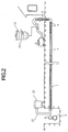
- FIG. 2 A second process of the method according to the present invention is illustrated in Fig. 2.
- a flake material supply apparatus 11 comprising a tank 11a into which a predetermined amount of flake material a is received in advance, is positioned near by with its outlet connected to the air blowing passage of the air blower 5. Further, an extra flake material receiving tank 13 is connected through a hose 12 to the second open end of the pipe 1.
- the flake material a is made of a synthetic short fiber which is a glass fiber, carbon fiber or polyester fiber. Such flake material is used as a reinforcing material to be embeded into the resin lining layer c so as to obtain a greatly reinforced lining layer stronger than a resin lining layer obtained in a conventional method.
- an air flow having a high speed is generated to cause the flake material (supplied from the flake material supplying apparatus 11) to fly into the meter riser 3. Then, by means of the same air flow, the flake material a is blown into and through the service pipe 1 toward the second open end thereof, so that the flake material will adhere to the surface of the resin lining layer in the pipe 1. As illustrated in Fig. 2, a small amount of extra flake material will be received into the extra flake material receiving tank 13 through the hose 12.
- FIG. 3 A third process of the method according to the present invention is illustrated in Fig. 3.
- a suction pump 15 is connected to the first open end of the service pipe 1, an extra resin receiving tank 16 is positioned near by with its inlet connected in the suction passage of the suction pump 15.
- a ball-like pig 14 is inserted into the pipe 1 through the second open end thereof. Then, the suction pump 15 is operated to produce a suction force, so that the pig 14 is caused to move from the second open end toward the first open end of the pipe 1.
- the ball-like pig 14 has a predetermined diameter such that with the movement of the pig 14 through the pipe 1, an even resin lining layer c having a desired uniform thickness f may be formed on the pipe internal surface. Also, while the ball-like pig 14 is moving through the pipe 1, the uncured resin lining layer c will be pressed against the pipe inner wall and kneaded circumferentially, so that the flake material a already adhered to the surface of the resin lining layer will be further embedded deep into the layer c . In this way, the resin lining layer c will be reinforced, so that it is possible not only to prevent the flowing away or flowing down of the uncured resin, but also to obtain a greatly reinforced resin lining layer stronger than a resin lining layer obtained in a conventional method.
- the extra resin will be caused to move out of the pipe 1 through the first open end thereof and be received in the extra resin receiving tank 16.
- a suction force generated by the suction pump 15 it is also possible to have an air blower (not shown) connected to the second open end of the pipe 1, so as to provide a pushing force to cause the pig 14 to move through the pipe 1 in the same manner.
- an even resin lining layer having a desired and uniform thickness may be formed on the internal surface of an existing underground pipe, with resin thickness on the top being equal to that on the bottom.
- the resin lining layer formed on the internal surface of the existing pipe will be greatly reinforced. Therefore, it is possible not only to prevent the flowing away or flowing down of the uncured resin layer, but also to obtain a greatly reinforced resin lining layer stronger than a resin lining layer obtained in a conventional method.
Abstract
- introducing a predetermined amount of a resin into one end of the pipe, and
- causing the resin to move through the pipe toward the other end thereof, so as to form a lining layer on the internal surface of the pipe: characterised by the further steps of introducing into the pipe a predetermined amount of solid particulate or flake material so that the flake material adheres to the surface of the resin;
- inserting into the pipe a pig of a predetermined diameter and causing the pig to move through the pipe along the entire length thereof, thereby embedding the flake material into the resin lining layer, and forming on the pipe internal surface an even resin lining layer having a desired uniform thickness.
Description
- The present invention relates to a method of lining the internal surface of a pipe, particularly to a method of lining the internal surface of an existing underground gas pipe, water pipe, etc. for the purpose of internal surface repair or rehabilitation thereof.
- There have been suggested various methods of lining the internal surface of an existing pipe with a resin so as to carry out pipeline internal surface repair or rehabilitation thereof. For instance, Japanese Patent Gazette 61-24067 discloses a method where a predetermined amount of a liquid resin is introduced into an existing pipe to be treated, and is forced to move through the pipe, by means of a high speed air flow, so that a desired resin lining layer is formed on the internal surface of the existing pipe.
- Figure 1 illustrate the above-mentioned prior art method. In Figure 1,
reference numeral 1 represents an existing underground pipe to be treated in the resin lining treatment, which is branching from amain pipe 2 and extending to a user's house. - In fact, the
pipe 1 is used as a service pipe including ameter riser 3 which extends out of ground surface. Themeter riser 3 is provided at one end thereof with a meter (not shown) which shall be removed therefrom so as to form a first open end for the resin lining operation. On the other hand, a pit A is formed by digging at a position where theservice pipe 1 is branching from themain pipe 2, so that the branching position is exposed and theservice pipe 1 is separated from themain pipe 2 by being separated from a service tee 4. In this way, a second open end is formed on theservice pipe 1 for the resin lining operation. - In lining operation, an
air blower 5 and a resin mixing/supplyingapparatus 6 are connected to the first open end of theservice pipe 1, whilst an extra resin receivingtank 8 is connected through ahose 7 to the second open end thereof. - By operating the
air blower 5, an air flow having a high speed is generated to cause a mixed liquid resin (supplied from the resin mixing/supplying apparatus 6) to flow into the meter rising 3. Then, by means of the same air flow, the resin is forced to flow into and through theservice pipe 1 toward the second open end thereof, so that a resin lining layer c is formed on the internal surface of thepipe 1. A small amount of an extra resin is caused to flow out of thepipe 1 so as to be received into thereceiving tank 8 via thehose 7. - However, in the above mentioned conventional method, the resin layer c formed on the internal surface of the
surface pipe 1, has at least the following two defects as shown in Figures 4 and 5. - As illustrated in Figure 4, before the resin lining layer c is solidified on the internal surface of the
pipe 1, the resin on the top will flow down to the bottom of the pipe, resulting in a problem that the upper half of the resin lining layer c has a relatively thin thickness d, whereas the lower half of the resin lining layer c has a relatively thick thickness e. - As illustrated in Figure 5, since a ripple phenomenon g can easily occur on the resin surface before the resin solidifies, the resin lining layer c finally formed on the inner wall of the
pipe 1 presents an uneven surface, resulting in a lining layer having a non-uniform thickness. - Since many experiments indicate that it is necessary to use a low viscosity resin which is suitably thixotropic so that the resin may be exactly transported through a pipe along the entire length thereof, the above two problems as shown in Figures 4 and 5 have proved difficult to overcome.
- The present invention therefore seeks to mitigate the above-mentioned problems of the prior art, and to provide an improved pipe lining method which is capable not only to solve the above problems, but also to obtain a greatly reinforced resin lining layer stronger than the resin lining layer obtained in a conventional method thereby achieving an improved rehabilitation effect for an existing pipe.
- According to the present invention there is provided a method for lining the internal surface of a pipe, said method comprising the steps of:
- introducing a predetermined amount of a resin into one end of the pipe, and
- causing the resin to move through the pipe toward the other end thereof, so as to form a lining layer on the internal surface of the pipe: characterised by the further steps of introducing into the pipe a predetermined amount of solid particulate or flake material so that the flake material adheres to the surface of the resin;
- inserting into the pipe a pig of a predetermined diameter and causing the pig to move through the pipe along the entire length thereof, thereby embedding the flake material into the resin lining layer, and forming on the pipe internal surface an even resin lining layer having a desired uniform thickness.
- In one aspect of the present invention, the flake material is embedded into the uncured resin layer so as to obtain a reinforced resin lining layer upon resin hardening. The flake material is made of a synthetic short fibre which is a glass fibre, carbon fibre or polyester fibre.
- Further, said predetermined amount of the flake material may be introduced into the pipe through either the first open end of the second open end of the pipe, by means of a high speed air flowing into the pipe, such that the flake material may adhere to the surface of the resin lining layer in the pipe.
- In another aspect of the present invention, the pig is caused to move through the pipe, either by virtue of a suction force generated by a suction pump, or by virtue of a pushing force generated by an air blower.
- Some embodiments of the present invention will now be described by way of example with reference to the accompanying drawings, in which:
- Figure 1 is an explanatory view illustrating a first process of the method according to the present invention, this process is also employed in a conventional method.
- Figure 2 is an explanatory view illustrating a second process of the method according to the present invention.
- Figure 3 is an explanatory view illustrating a third process of the method according to the present invention.
- Figure 4 is a lateral cross sectional view illustrating a resin lining layer forced on the internal surface of an existing pipe, using a conventional method.
- Figure 5 is a longitudinal cross sectional and partially elevational view illustrating a resin lining layer formed on the internal surface of an existing pipe, using a conventional method.
- One embodiment of a method according to the present invention will be described in detail below, with reference to the accompanying drawings including Figs. 1 - 3.
- Referring to Fig. 1,
reference numeral 1 represents an existing underground pipe to be treated in the resin lining treatment, which is branching from a main pipe 2 (buried on road side) and extending to a user's house. - In fact, the
pipe 1 is used as a service pipe including ameter riser 3 which extends out of ground surface. Themeter riser 3 is provided at one end thereof with a meter (not shown) which shall be removed therefrom so as to form a first open end for the resin lining operation. On the other hand, a pit A is formed by digging at a position where theservice pipe 1 is branching from themain pipe 2, so that the branching position is exposed and theservice pipe 1 is separated from themain pipe 2 by being separated from a service tee 4. In this way, a second open end is formed on theservice pipe 1 for the resin lining operation. - A first process of the method according to the present invention is illustrated in Fig. 1, which is carried out in the same manner using the same equipments as the above-discussed prior art.
- Namely, before the lining operation, an
air blower 5 and a resin mixing/supplyingapparatus 6 are connected to the first open end of theservice pipe 1, whilst an extra resin receivingtank 8 is connected through ahose 7 to the second open end thereof. - By operating the
air blower 5, an air flow having a high speed is generated to cause a mixed liquid resin (supplied from the resin mixing/supplying apparatus 6) to flow into themeter riser 3. Then, by means of the same air flow, the resin is forced to flow into and through theservice pipe 1 toward the second open end thereof, so that a resin lining layer c is formed on the internal surface of thepipe 1. A small amount of an extra resin is caused to flow out of thepipe 1 so as to be received into thereceiving tank 8 via thehose 7. - A second process of the method according to the present invention is illustrated in Fig. 2.
- As shown in Fig. 2, the
air blower 5 remains in the same condition as in the first process, a flakematerial supply apparatus 11 comprising a tank 11a into which a predetermined amount of flake material a is received in advance, is positioned near by with its outlet connected to the air blowing passage of theair blower 5. Further, an extra flakematerial receiving tank 13 is connected through ahose 12 to the second open end of thepipe 1. - Here, the flake material a is made of a synthetic short fiber which is a glass fiber, carbon fiber or polyester fiber. Such flake material is used as a reinforcing material to be embeded into the resin lining layer c so as to obtain a greatly reinforced lining layer stronger than a resin lining layer obtained in a conventional method.
- By operating the
air blower 5, an air flow having a high speed is generated to cause the flake material (supplied from the flake material supplying apparatus 11) to fly into themeter riser 3. Then, by means of the same air flow, the flake material a is blown into and through theservice pipe 1 toward the second open end thereof, so that the flake material will adhere to the surface of the resin lining layer in thepipe 1. As illustrated in Fig. 2, a small amount of extra flake material will be received into the extra flakematerial receiving tank 13 through thehose 12. - Although it is illustrated in Fig. 2 that the flake material a is introduced into the
service pipe 1 through the first open end thereof (on the meter riser 3), it is also possible to introduce the flake material a into thepipe 1 through the second open end (in the pit A). - A third process of the method according to the present invention is illustrated in Fig. 3.
- As shown in Fig. 3, a
suction pump 15 is connected to the first open end of theservice pipe 1, an extraresin receiving tank 16 is positioned near by with its inlet connected in the suction passage of thesuction pump 15. - At first, a ball-
like pig 14 is inserted into thepipe 1 through the second open end thereof. Then, thesuction pump 15 is operated to produce a suction force, so that thepig 14 is caused to move from the second open end toward the first open end of thepipe 1. - The ball-
like pig 14 has a predetermined diameter such that with the movement of thepig 14 through thepipe 1, an even resin lining layer c having a desired uniform thickness f may be formed on the pipe internal surface. Also, while the ball-like pig 14 is moving through thepipe 1, the uncured resin lining layer c will be pressed against the pipe inner wall and kneaded circumferentially, so that the flake material a already adhered to the surface of the resin lining layer will be further embedded deep into the layer c. In this way, the resin lining layer c will be reinforced, so that it is possible not only to prevent the flowing away or flowing down of the uncured resin, but also to obtain a greatly reinforced resin lining layer stronger than a resin lining layer obtained in a conventional method. - After the formation of the even resin lining layer c having a uniform thickness, the extra resin will be caused to move out of the
pipe 1 through the first open end thereof and be received in the extraresin receiving tank 16. - Although, it is illustrated in Fig. 3 that the ball-
like pig 14 is forced to move through thepipe 1 by a suction force generated by thesuction pump 15, it is also possible to have an air blower (not shown) connected to the second open end of thepipe 1, so as to provide a pushing force to cause thepig 14 to move through thepipe 1 in the same manner. - Clearly, it is essential that the above-described second and third processes should be performed before the resin lining layer c formed during the above first process becomes hardened.
- It is understood from the above description that, with the use of the method according to the present invention, an even resin lining layer having a desired and uniform thickness may be formed on the internal surface of an existing underground pipe, with resin thickness on the top being equal to that on the bottom.
- Moreover, with the use of the method according to the present invention, since a flake material made of a synthetic short fiber is caused to adhere to the uncured resin layer and is further embedded deep into the resin layer, the resin lining layer formed on the internal surface of the existing pipe will be greatly reinforced. Therefore, it is possible not only to prevent the flowing away or flowing down of the uncured resin layer, but also to obtain a greatly reinforced resin lining layer stronger than a resin lining layer obtained in a conventional method.
- While the presently preferred embodiments of the this invention have been shown and described above, it is to be understood that these disclosures are for the purpose of illustration and that various changes and modifications may be made without departing form the scope of the invention as set forth in the appended claims.
Claims (10)
- A method for lining the internal surface of a pipe, said method comprising the steps of:introducing a predetermined amount of a resin into one end of the pipe, andcausing the resin to move through the pipe toward the other end thereof, so as to form a lining layer on the internal surface of the pipe: characterised by the further steps of introducing into the pipe a predetermined amount of solid particulate or flake material so that the flake material adheres to the surface of the resin;inserting into the pipe a pig of a predetermined diameter and causing the pig to move through the pipe along the entire length thereof, thereby embedding the flake material into the resin lining layer, and forming on the pipe internal surface an even resin lining layer having a desired uniform thickness.
- A method according to claim 1 in which the pig is spherical.
- A method according to claim 1 or claim 2 wherein the solid material is embedded into resin layer before it has set so as to obtain a reinforced resin lining layer when the resin hardens.
- A method according to any preceding claim wherein the solid material comprises short synthetic fibres.
- A method according to claim 3, wherein the short synthetic short fibre comprises glass fibre, carbon fibre or polyester fibre.
- A method according to any preceding claim wherein the solid material is introduced into the pipe by means of high speed air flow.
- A method according to any preceding claim, wherein a solid material receiving means is provided at the end of the pipe opposite to the end through which the material is introduced into the pipe.
- A method according to any preceding claim wherein the pig is caused to move through the pipe by suction generated by a suction pump.
- A method according to any one of claims 1 to 7, wherein the pig is caused to move through the pipe by pressure generated by an air blower.
- A method according to any preceding claim wherein a resin receiving means is provided at the end of the pipe opposite to the end through which the pig is introduced.
Applications Claiming Priority (3)
| Application Number | Priority Date | Filing Date | Title |
|---|---|---|---|
| JP7280889A JPH09117720A (en) | 1995-10-27 | 1995-10-27 | Method for lining inner face of existing pipeline |
| JP280889/95 | 1995-10-27 | ||
| JP28088995 | 1995-10-27 |
Publications (2)
| Publication Number | Publication Date |
|---|---|
| EP0770811A1 true EP0770811A1 (en) | 1997-05-02 |
| EP0770811B1 EP0770811B1 (en) | 2000-08-09 |
Family
ID=17631362
Family Applications (1)
| Application Number | Title | Priority Date | Filing Date |
|---|---|---|---|
| EP96301634A Expired - Lifetime EP0770811B1 (en) | 1995-10-27 | 1996-03-11 | Method for lining a pipe |
Country Status (6)
| Country | Link |
|---|---|
| US (1) | US5590689A (en) |
| EP (1) | EP0770811B1 (en) |
| JP (1) | JPH09117720A (en) |
| CA (1) | CA2170954C (en) |
| DE (1) | DE69609689T2 (en) |
| ES (1) | ES2150634T3 (en) |
Families Citing this family (5)
| Publication number | Priority date | Publication date | Assignee | Title |
|---|---|---|---|---|
| JP3300268B2 (en) * | 1997-12-10 | 2002-07-08 | 東京瓦斯株式会社 | Rehabilitation repair method for existing pipeline |
| GB2372055B (en) * | 2001-02-07 | 2004-09-22 | Petroleo Brasileiro Sa | Method of diminishing the cross section of an opening of a hollow device located in a flow pipe |
| JP4842869B2 (en) * | 2007-03-28 | 2011-12-21 | 株式会社湘南合成樹脂製作所 | Auxiliary device for filling pipe with fluid and fluid injection method for injecting fluid into pipe |
| EP3001827B1 (en) | 2014-08-08 | 2018-01-17 | Envirologics Engineeering Inc. | Method and apparatus to line pipe homogeneously |
| US20230323995A1 (en) * | 2022-04-07 | 2023-10-12 | Carboshield, Inc. | Composite reinforcement of tubular structures |
Citations (5)
| Publication number | Priority date | Publication date | Assignee | Title |
|---|---|---|---|---|
| US4327132A (en) * | 1979-10-01 | 1982-04-27 | Kiyonori Shinno | Method for lining of inner surface of a pipe |
| JPS58189073A (en) * | 1982-04-30 | 1983-11-04 | Hakko Co Ltd | Method for repairing inner surface of existing pipe line |
| US4440194A (en) * | 1980-02-29 | 1984-04-03 | Osaka Gas Company, Limited | Moving body and method of performing work within pipes with use of same |
| US5230842A (en) * | 1989-02-21 | 1993-07-27 | Munde Bruce A | Interior pipeline coating process |
| US5443377A (en) * | 1991-11-13 | 1995-08-22 | Mainlining Service, Inc. | Increased efficiency apparatus for lining a pipe with a cement mortar |
Family Cites Families (6)
| Publication number | Priority date | Publication date | Assignee | Title |
|---|---|---|---|---|
| US4397890A (en) * | 1982-01-29 | 1983-08-09 | Osaka Gas Company, Limited | Method of lining pipes |
| US4600548A (en) * | 1983-01-10 | 1986-07-15 | Vinen Corp. | Method of forming the primary core of a prestressed concrete pipe |
| GB8530720D0 (en) * | 1985-12-13 | 1986-01-22 | Bio Kil Chemicals Ltd | Applying protective coating |
| US5265648A (en) * | 1989-08-07 | 1993-11-30 | Great Lakes And Southern Research Limited Prtnshp. | Pipe liner and method of installation thereof |
| US5246641A (en) * | 1991-11-13 | 1993-09-21 | Mainlining Service, Inc. | Method for lining a pipe with a cement mortar |
| EP0593264B1 (en) * | 1992-10-14 | 1997-01-08 | Tokyo Gas Co., Ltd. | Method of lining an inner surface of a pipe |
-
1995
- 1995-10-27 JP JP7280889A patent/JPH09117720A/en active Pending
-
1996
- 1996-03-01 US US08/609,782 patent/US5590689A/en not_active Expired - Fee Related
- 1996-03-04 CA CA002170954A patent/CA2170954C/en not_active Expired - Fee Related
- 1996-03-11 ES ES96301634T patent/ES2150634T3/en not_active Expired - Lifetime
- 1996-03-11 EP EP96301634A patent/EP0770811B1/en not_active Expired - Lifetime
- 1996-03-11 DE DE69609689T patent/DE69609689T2/en not_active Expired - Fee Related
Patent Citations (5)
| Publication number | Priority date | Publication date | Assignee | Title |
|---|---|---|---|---|
| US4327132A (en) * | 1979-10-01 | 1982-04-27 | Kiyonori Shinno | Method for lining of inner surface of a pipe |
| US4440194A (en) * | 1980-02-29 | 1984-04-03 | Osaka Gas Company, Limited | Moving body and method of performing work within pipes with use of same |
| JPS58189073A (en) * | 1982-04-30 | 1983-11-04 | Hakko Co Ltd | Method for repairing inner surface of existing pipe line |
| US5230842A (en) * | 1989-02-21 | 1993-07-27 | Munde Bruce A | Interior pipeline coating process |
| US5443377A (en) * | 1991-11-13 | 1995-08-22 | Mainlining Service, Inc. | Increased efficiency apparatus for lining a pipe with a cement mortar |
Non-Patent Citations (1)
| Title |
|---|
| PATENT ABSTRACTS OF JAPAN vol. 008, no. 024 (C - 208) 2 February 1984 (1984-02-02) * |
Also Published As
| Publication number | Publication date |
|---|---|
| US5590689A (en) | 1997-01-07 |
| EP0770811B1 (en) | 2000-08-09 |
| DE69609689D1 (en) | 2000-09-14 |
| CA2170954C (en) | 2000-04-25 |
| DE69609689T2 (en) | 2001-04-12 |
| ES2150634T3 (en) | 2000-12-01 |
| CA2170954A1 (en) | 1997-04-28 |
| JPH09117720A (en) | 1997-05-06 |
Similar Documents
| Publication | Publication Date | Title |
|---|---|---|
| US4401696A (en) | Lining of pipelines and passageways | |
| WO1993013350A1 (en) | Improvements in or relating to the lining of passageways | |
| EP0094819B1 (en) | Pipe linings | |
| EP0713048A1 (en) | Method of lining the internal surface of a pipe | |
| EP0770811B1 (en) | Method for lining a pipe | |
| US5983948A (en) | Method of repairing an existing pipeline including a main pipe and a branch pipe | |
| JP2000054368A (en) | High-pressure jet mixing ground-improvement method | |
| WO1985003758A1 (en) | Method and apparatus for the plugging of side openings of sewage pipes, particularly side or branch pipes of main sewer conduits | |
| JPS6110632A (en) | Method of repairing existing piping | |
| JPH01235740A (en) | Repairing of inner surface of existing pipe | |
| JPS6058274A (en) | Method for lining pipe inner wall | |
| JPS6021790B2 (en) | Leak prevention method for existing buried pipes, etc. | |
| JPH02298388A (en) | Method for painting branched pipeline | |
| WO1994008105A1 (en) | Improvements relating to the cleaning of pipelines and passageways | |
| JPH08219365A (en) | Existing pipeline repairing method and hose used therefor | |
| JPS58189073A (en) | Method for repairing inner surface of existing pipe line | |
| JP2821539B2 (en) | Resin lining repair method for internal pipes with narrow portions | |
| JPS5938028B2 (en) | Leak prevention method for existing buried pipes, etc. | |
| JPH0346192B2 (en) | ||
| JPH0649182B2 (en) | Pipe inner surface lining repair method | |
| JP2665922B2 (en) | Repair method for lining of pipe inner surface | |
| JPH0655296B2 (en) | Pipe inner surface lining repair method | |
| JPH0649183B2 (en) | Pipe inner surface lining repair method | |
| JPH0459955B2 (en) | ||
| JP2002219406A (en) | Method of lining inside of pipe |
Legal Events
| Date | Code | Title | Description |
|---|---|---|---|
| PUAI | Public reference made under article 153(3) epc to a published international application that has entered the european phase |
Free format text: ORIGINAL CODE: 0009012 |
|
| 17P | Request for examination filed |
Effective date: 19960410 |
|
| AK | Designated contracting states |
Kind code of ref document: A1 Designated state(s): DE ES FR GB IT |
|
| GRAG | Despatch of communication of intention to grant |
Free format text: ORIGINAL CODE: EPIDOS AGRA |
|
| 17Q | First examination report despatched |
Effective date: 19991012 |
|
| GRAG | Despatch of communication of intention to grant |
Free format text: ORIGINAL CODE: EPIDOS AGRA |
|
| GRAH | Despatch of communication of intention to grant a patent |
Free format text: ORIGINAL CODE: EPIDOS IGRA |
|
| GRAH | Despatch of communication of intention to grant a patent |
Free format text: ORIGINAL CODE: EPIDOS IGRA |
|
| GRAA | (expected) grant |
Free format text: ORIGINAL CODE: 0009210 |
|
| AK | Designated contracting states |
Kind code of ref document: B1 Designated state(s): DE ES FR GB IT |
|
| REF | Corresponds to: |
Ref document number: 69609689 Country of ref document: DE Date of ref document: 20000914 |
|
| ET | Fr: translation filed | ||
| ITF | It: translation for a ep patent filed |
Owner name: BIANCHETTI - BRACCO - MINOJA S.R.L. |
|
| REG | Reference to a national code |
Ref country code: ES Ref legal event code: FG2A Ref document number: 2150634 Country of ref document: ES Kind code of ref document: T3 |
|
| PLBE | No opposition filed within time limit |
Free format text: ORIGINAL CODE: 0009261 |
|
| STAA | Information on the status of an ep patent application or granted ep patent |
Free format text: STATUS: NO OPPOSITION FILED WITHIN TIME LIMIT |
|
| 26N | No opposition filed | ||
| REG | Reference to a national code |
Ref country code: GB Ref legal event code: IF02 |
|
| PGFP | Annual fee paid to national office [announced via postgrant information from national office to epo] |
Ref country code: ES Payment date: 20030212 Year of fee payment: 8 |
|
| PGFP | Annual fee paid to national office [announced via postgrant information from national office to epo] |
Ref country code: FR Payment date: 20030226 Year of fee payment: 8 |
|
| PGFP | Annual fee paid to national office [announced via postgrant information from national office to epo] |
Ref country code: GB Payment date: 20030228 Year of fee payment: 8 |
|
| PGFP | Annual fee paid to national office [announced via postgrant information from national office to epo] |
Ref country code: DE Payment date: 20030331 Year of fee payment: 8 |
|
| PG25 | Lapsed in a contracting state [announced via postgrant information from national office to epo] |
Ref country code: GB Free format text: LAPSE BECAUSE OF NON-PAYMENT OF DUE FEES Effective date: 20040311 |
|
| PG25 | Lapsed in a contracting state [announced via postgrant information from national office to epo] |
Ref country code: ES Free format text: LAPSE BECAUSE OF NON-PAYMENT OF DUE FEES Effective date: 20040312 |
|
| PG25 | Lapsed in a contracting state [announced via postgrant information from national office to epo] |
Ref country code: DE Free format text: LAPSE BECAUSE OF NON-PAYMENT OF DUE FEES Effective date: 20041001 |
|
| GBPC | Gb: european patent ceased through non-payment of renewal fee |
Effective date: 20040311 |
|
| PG25 | Lapsed in a contracting state [announced via postgrant information from national office to epo] |
Ref country code: FR Free format text: LAPSE BECAUSE OF NON-PAYMENT OF DUE FEES Effective date: 20041130 |
|
| REG | Reference to a national code |
Ref country code: FR Ref legal event code: ST |
|
| PG25 | Lapsed in a contracting state [announced via postgrant information from national office to epo] |
Ref country code: IT Free format text: LAPSE BECAUSE OF NON-PAYMENT OF DUE FEES Effective date: 20050311 |
|
| REG | Reference to a national code |
Ref country code: ES Ref legal event code: FD2A Effective date: 20040312 |