EP0770494A2 - A method for making a lithographic printing plate involving on press development - Google Patents
A method for making a lithographic printing plate involving on press development Download PDFInfo
- Publication number
- EP0770494A2 EP0770494A2 EP95202874A EP95202874A EP0770494A2 EP 0770494 A2 EP0770494 A2 EP 0770494A2 EP 95202874 A EP95202874 A EP 95202874A EP 95202874 A EP95202874 A EP 95202874A EP 0770494 A2 EP0770494 A2 EP 0770494A2
- Authority
- EP
- European Patent Office
- Prior art keywords
- imaging element
- image
- image forming
- forming layer
- hydrophilic
- Prior art date
- Legal status (The legal status is an assumption and is not a legal conclusion. Google has not performed a legal analysis and makes no representation as to the accuracy of the status listed.)
- Granted
Links
Images

Classifications
-
- B—PERFORMING OPERATIONS; TRANSPORTING
- B41—PRINTING; LINING MACHINES; TYPEWRITERS; STAMPS
- B41M—PRINTING, DUPLICATING, MARKING, OR COPYING PROCESSES; COLOUR PRINTING
- B41M5/00—Duplicating or marking methods; Sheet materials for use therein
- B41M5/26—Thermography ; Marking by high energetic means, e.g. laser otherwise than by burning, and characterised by the material used
- B41M5/36—Thermography ; Marking by high energetic means, e.g. laser otherwise than by burning, and characterised by the material used using a polymeric layer, which may be particulate and which is deformed or structurally changed with modification of its' properties, e.g. of its' optical hydrophobic-hydrophilic, solubility or permeability properties
- B41M5/366—Thermography ; Marking by high energetic means, e.g. laser otherwise than by burning, and characterised by the material used using a polymeric layer, which may be particulate and which is deformed or structurally changed with modification of its' properties, e.g. of its' optical hydrophobic-hydrophilic, solubility or permeability properties using materials comprising a polymeric matrix containing a polymeric particulate material, e.g. hydrophobic heat coalescing particles
-
- B—PERFORMING OPERATIONS; TRANSPORTING
- B41—PRINTING; LINING MACHINES; TYPEWRITERS; STAMPS
- B41C—PROCESSES FOR THE MANUFACTURE OR REPRODUCTION OF PRINTING SURFACES
- B41C1/00—Forme preparation
- B41C1/10—Forme preparation for lithographic printing; Master sheets for transferring a lithographic image to the forme
- B41C1/1008—Forme preparation for lithographic printing; Master sheets for transferring a lithographic image to the forme by removal or destruction of lithographic material on the lithographic support, e.g. by laser or spark ablation; by the use of materials rendered soluble or insoluble by heat exposure, e.g. by heat produced from a light to heat transforming system; by on-the-press exposure or on-the-press development, e.g. by the fountain of photolithographic materials
- B41C1/1025—Forme preparation for lithographic printing; Master sheets for transferring a lithographic image to the forme by removal or destruction of lithographic material on the lithographic support, e.g. by laser or spark ablation; by the use of materials rendered soluble or insoluble by heat exposure, e.g. by heat produced from a light to heat transforming system; by on-the-press exposure or on-the-press development, e.g. by the fountain of photolithographic materials using materials comprising a polymeric matrix containing a polymeric particulate material, e.g. hydrophobic heat coalescing particles
-
- B—PERFORMING OPERATIONS; TRANSPORTING
- B41—PRINTING; LINING MACHINES; TYPEWRITERS; STAMPS
- B41C—PROCESSES FOR THE MANUFACTURE OR REPRODUCTION OF PRINTING SURFACES
- B41C2210/00—Preparation or type or constituents of the imaging layers, in relation to lithographic printing forme preparation
- B41C2210/04—Negative working, i.e. the non-exposed (non-imaged) areas are removed
-
- B—PERFORMING OPERATIONS; TRANSPORTING
- B41—PRINTING; LINING MACHINES; TYPEWRITERS; STAMPS
- B41C—PROCESSES FOR THE MANUFACTURE OR REPRODUCTION OF PRINTING SURFACES
- B41C2210/00—Preparation or type or constituents of the imaging layers, in relation to lithographic printing forme preparation
- B41C2210/08—Developable by water or the fountain solution
-
- B—PERFORMING OPERATIONS; TRANSPORTING
- B41—PRINTING; LINING MACHINES; TYPEWRITERS; STAMPS
- B41C—PROCESSES FOR THE MANUFACTURE OR REPRODUCTION OF PRINTING SURFACES
- B41C2210/00—Preparation or type or constituents of the imaging layers, in relation to lithographic printing forme preparation
- B41C2210/24—Preparation or type or constituents of the imaging layers, in relation to lithographic printing forme preparation characterised by a macromolecular compound or binder obtained by reactions involving carbon-to-carbon unsaturated bonds, e.g. acrylics, vinyl polymers
Definitions
- the present invention relates to a method for making a lithographic printing plate. More in particular, the present invention relates to a method wherein the lithographic printing plate is developed on the printing press subsequent to image-wise exposure.
- Lithography is the process of printing from specially prepared surfaces, some areas of which are capable of accepting lithographic ink, whereas other areas, when moistened with water, will not accept the ink.
- the areas which accept ink form the printing image areas and the ink-rejecting areas form the background areas.
- a photographic material is made imagewise receptive to oily or greasy inks in the photo-exposed (negative-working) or in the non-exposed areas (positive-working) on a hydrophilic background.
- lithographic printing plates also called surface litho plates or planographic printing plates
- a support that has affinity to water or obtains such affinity by chemical treatment is coated with a thin layer of a photosensitive composition.
- Coatings for that purpose include light-sensitive polymer layers containing diazo compounds, dichromate-sensitized hydrophilic colloids and a large variety of synthetic photopolymers. Particularly diazo-sensitised systems are widely used.
- the exposed image areas become insoluble and the unexposed areas remain soluble.
- the plate is then developed with a suitable liquid to remove the diazonium salt or diazo resin in the unexposed areas.
- Lithocraft 10008 FOTOPLATETM is a diazo based printing plate that comprises on a paper support a hydrophilic layer on top of which is provided a diazo based photosensitive layer.
- a plate can be prepared by image-wise exposure of the lithographic printing plate precursor or imaging element, mounting the exposed imaging element on the press and wiping its surface with Lithocraft® 10008 Developer Desensitiser.
- the plate instructions also contemplate a method wherein no developer desensitizer is used. However, such method most often results in poor lithographic preformance so that in practice a Developer Desensitiser is almost always needed.
- a particular disadvantage of photosensitive imaging elements such as described above for making a printing plate is that they have to be shielded from the light. This is a particular disadvantage if on press development is contemplated since mounting the image-wise exposed imaging element is generally done in normal daylight so that the handling time for mounting the imaging element is limited. Moreover, diazo based aluminium type printing plates are completely unsuitable for on press development.
- a method for making a lithographic printing plate comprising the steps of:
- the present invention further provides a method for making multiple copies of an orginal image comprising the steps of:
- the present invention further relates to a method for making a lithographic printing plate comprising the steps of:
- the present invention also discloses a method for making multiple copies from an original comprising the steps of:
- the present invention also describes a printing apparatus comprising:
- the present invention relates to a method for making a lithographic printing plate comprising the steps of:
- An imaging element for use in accordance with the present invention comprises on a hydrophilic surface of a lithographic base an image forming layer comprising hydrophobic thermoplastic polymer particles dispersed in a hydrophilic binder.
- the hydrophilic binder used in connection with the present invention is perferably not cross-linked or only sightly cross-linked.
- the imaging element further includes a compound capable of converting light to heat. This compound is preferably comprised in the image forming layer but can also be provided in a layer adjacent to the image forming layer.
- the lithographic base can be an anodised aluminium.
- a particularly preferred lithographic base is an electrochemically grained and anodised aluminium support.
- an anodised aluminium support may be treated to improve the hydrophilic properties of its surface.
- the aluminium support may be silicated by treating its surface with sodium silicate solution at elevated temperature, e.g. 95°C.
- a phosphate treatment may be applied which involves treating the aluminium oxide surface with a phosphate solution that may further contain an inorganic fluoride.
- the aluminium oxide surface may be rinsed with a citric acid or citrate solution.
- This treatment may be carried out at room temperature or can be carried out at a slightly elevated temperature of about 30 to 50°C.
- a further interesting treatment involves rinsing the aluminium oxide surface with a bicarbonate solution. It is further evident that one or more of these post treatments may be carried out alone or in combination.
- the lithographic base comprises a flexible support, such as e.g. paper or plastic film, provided with a cross-linked hydrophilic layer.
- a particularly suitable cross-linked hydrophilic layer may be obtained from a hydrophilic binder cross-linked with a cross-linking agent such as formaldehyde, glyoxal, polyisocyanate or a hydrolysed tetra-alkylorthosilicate. The latter is particularly preferred.
- hydrophilic binder there may be used hydrophilic (co)polymers such as for example, homopolymers and copolymers of vinyl alcohol, acrylamide, methylol acrylamide, methylol methacrylamide, acrylic acid, methacrylic acid, hydroxyethyl acrylate, hydroxyethyl methacrylate or maleic anhydride/vinylmethylether copolymers.
- the hydrophilicity of the (co)polymer or (co)polymer mixture used is preferably the same as or higher than the hydrophilicity of polyvinyl acetate hydrolyzed to at least an extent of 60 percent by weight, preferably 80 percent by weight.
- the amount of crosslinking agent, in particular of tetraalkyl orthosilicate, is preferably at least 0.2 parts by weight per part by weight of hydrophilic binder, preferably between 0.5 and 5 parts by weight, more preferably between 1.0 parts by weight and 3 parts by weight.
- a cross-linked hydrophilic layer in a lithographic base used in accordance with the present embodiment preferably also contains substances that increase the mechanical strength and the porosity of the layer.
- colloidal silica may be used.
- the colloidal silica employed may be in the form of any commercially available water-dispersion of colloidal silica for example having an average particle size up to 40 nm, e.g. 20 nm.
- inert particles of larger size than the colloidal silica can be added e.g. silica prepared according to Stöber as described in J. Colloid and Interface Sci., Vol.
- alumina particles or particles having an average diameter of at least 100 nm which are particles of titanium dioxide or other heavy metal oxides.
- the thickness of a cross-linked hydrophilic layer in a lithographic base in accordance with this embodiment may vary in the range of 0.2 to 25 ⁇ m and is preferably 1 to 10 ⁇ m.
- cross-linked hydrophilic layers for use in accordance with the present invention are disclosed in EP-A 601240, GB-P-1419512, FR-P-2300354, US-P-3971660, US-P-4284705 and EP-A 514490.
- plastic film e.g. substrated polyethylene terephthalate film, cellulose acetate film, polystyrene film, polycarbonate film etc.
- the plastic film support may be opaque or transparent.
- the amount of silica in the adhesion improving layer is 200 mg per m 2 and 750 mg per m 2 .
- the ratio of silica to hydrophilic binder is preferably more than 1 and the surface area of the colloidal silica is preferably at least 300 m 2 per gram, more preferably a surface area of 500 m 2 per gram.
- an image forming layer on top of a hydrophilic surface there is provided an image forming layer.
- an image forming layer in connection with the present invention comprises thermoplastic polymer particles dispersed in a hydrophilic binder.
- Suitable hydrophilic binders for use in an image forming layer in connection with this invention are for example synthetic homo or copolymers such as a polyvinylalcohol, a poly(meth)acrylic acid, a poly(meth)acrylamide, a polyhydroxyethyl(meth)acrylate, a polyvinylmethylether or natural binders such as gelatin, a polysacharide such as e.g. dextran, pullulan, cellulose, arabic gum, alginic acid.
- Hydrophobic thermoplastic polymer particles used in connection with the present invention preferably have a coagulation temperature above 35°C and more preferably above 50°C. Coagulation may result from softening or melting of the thermoplastic polymer particles under the influence of heat. There is no specific upper limit to the coagulation temperature of the thermoplastic hydrophobic polymer particles, however the temperature should be sufficiently below the decomposition of the polymer particles. Preferably the coagulation temperature is at least 10°C below the temperature at which the decomposition of the polymer particles occurs.
- said polymer particles When said polymer particles are subjected to a temperature above coagulation temperature they coagulate to form a hydrophobic agglomerate in the hydrophilic layer so that at these parts the hydrophilic layer becomes insoluble in plain water or an aqueous liquid.
- hydrophobic polymer particles for use in connection with the present invention are e.g. polyethylene, polyvinyl chloride, polymethyl (meth)acrylate, polyethyl (meth)acrylate, polyvinylidene chloride, polyacrylonitrile, polyvinyl carbazole etc. or copolymers thereof. Most preferably used is polyethylene.
- the weight average molecular weight of the polymers may range from 5,000 to 1,000,000g/mol.
- the hydrophobic particles may have a particle size from 0.01 ⁇ m to 50 ⁇ m, more preferably between 0.05mm and 10mm and most preferably between 0.05 ⁇ m and 2 ⁇ m.
- the polymer particles are present as a dispersion in the aqueous coating liquid of the image forming layer and may be prepared by the methods disclosed in US-P-3.476.937. Another method especially suitable for preparing an aqueous dispersion of the thermoplastic polymer particles comprises:
- the amount of hydrophobic thermoplastic polymer particles contained in the image forming layer is preferably between 20% by weight and 65% by weight and more preferably between 25% by weight and 55% by weight and most preferably between 30% by weight and 45% by weight.
- Suitable compounds capable of converting light into heat are preferably infrared absorbing components although the wavelength of absorption is not of particular importance as long as the absorption of the compound used is in the wavelength range of the light source used for image-wise exposure.
- Particularly useful compounds are for example dyes and in particular infrared dyes, carbon black, metal carbides, borides, nitrides, carbonitrides, bronze-structured oxides and oxides structurally related to the bronze family but lacking the A component e.g. WO 2.9 .
- conductive polymer dispersion such as polypyrrole or polyaniline-based conductive polymer dispersions.
- the lithographic performance and in particular the print endurance obtained depends on the heat-sensitivity of the imaging element. In this respect it has been found that carbon black yields very good and favorable results.
- a light to heat converting compound in connection with the present invention is most preferably added to the image forming layer but at least part of the light to heat converting compound may also be comprised in a neighbouring layer.
- Such layer can be for example the cross-linked hydrophilic layer of a lithographic base according to the second embodiment of lithographic bases explained above.
- the imaging element is image-wise exposed and subsequently is mounted on a print cylinder of a printing press.
- the printing press is then started and while the print cylinder with the imaging element mounted thereon rotates, the dampener rollers that supply dampening liquid are dropped on the imaging element and subsequent thereto the ink rollers are dropped.
- the dampener rollers that supply dampening liquid are dropped on the imaging element and subsequent thereto the ink rollers are dropped.
- the first clear and useful prints are obtained.
- the ink rollers and dampener rollers may be dropped simultaneously or the ink rollers may be dropped first.
- Suitable dampening liquids that can be used in connection with the present invention are aqueous liquids generally having an acidic pH and comprising an alcohol such as isopropanol.
- dampening liquids useful in the present invention there is no particular limitation and commercially available dampening liquids, also known as fountain solutions, can be used.
- an image-wise exposed imaging element e.g. a cotton pad or sponge soaked with water before mounting the imaging element on the press or at least before the printing press starts running. This will remove some non-image areas but will not actually develop the imaging element.
- it has the advantage that possible substantial contamination of the dampening system of the press and ink used is avoided.
- the imaging element is first mounted on the print cylinder of the printing press and then image-wise exposed directly on the press. Subsequent to exposure, the imaging element can be developed as described above.
- the imaging element may be image-wise exposed and subsequently developed by rinsing it with plain water.
- Image-wise exposure in connection with the present invention is preferably an image-wise scanning exposure involving the use of a laser or L.E.D.. It is highly preferred in connection with the present invention to use a laser emitting in the infrared (IR) and/or near-infrared, i.e. emitting in the wavelength range 700-1500nm. Particularly preferred for use in connection with the present invention are laser diodes emitting in the near-infrared.
- IR infrared
- near-infrared i.e. emitting in the wavelength range 700-1500nm.
- laser diodes emitting in the near-infrared are particularly preferred for use in connection with the present invention.
- a preferred imaging apparatus suitable for image-wise scanning exposure in accordance with the present invention preferably includes a laser output that can be provided directly to the imaging elements surface via lenses or other beam-guiding components, or transmitted to the surface of a blank imaging element from a remotely sited laser using a fiber-optic cable.
- a controller and associated positioning hardware maintains the beam output at a precise orientation with respect to the imaging elements surface, scans the output over the surface, and activates the laser at positions adjacent selected points or areas of the imaging element.
- the controller responds to incoming image signals corresponding to the original document and/or picture being copied onto the imaging element to produce a precise negative or positive image of that original.
- the image signals are stored as a bitmap data file on a computer.
- Such files may be generated by a raster image processor (RIP) or other suitable means.
- a RIP can accept Input data in page-description language, which defines all of the features required to be transferred onto the imaging element, or as a combination of page-description language and one or more image data files.
- the bitmaps are constructed to define the hue of the color as well as screen frequencies and angles in case of amplitude modulation screening.
- the present invention is particularly suitable for use in combination with frequency modulation screening as disclosed in e.g. EP-A 571010, EP-A 620677 and EP-A 620674.
- the imaging apparatus can operate on its own, functioning solely as a platemaker, or can be incorporated directly into a lithographic printing press having means for supplying a dampening liquid. In the latter case, printing may commence immediately after image-wise exposure and development, thereby reducing press set-up time considerably.
- the imaging apparatus can be configured as a flatbed recorder or as a drum recorder, with the lithographic plate blank mounted to the interior or exterior cylindrical surface of the drum.
- the exterior drum design is more appropriate to use in situ, on a lithographic press, in which case the print cylinder itself constitutes the drum component of the recorder or plotter.
- the requisite relative motion between the laser beam and the imaging element is achieved by rotating the drum(and the imaging element mounted thereon) about its axis and moving the beam parallel to the rotation axis, thereby scanning the imaging element circumferentially so the image "grows" in the axial direction.
- the beam can move parallel to the drum axis and, after each pass across the imaging element, increment angularly so that the image on the imaging element "grows" circumferentially.
- an image corresponding to the original will have been applied to the surface of the imaging element.
- the beam is drawn across either axis of the imaging element, and is indexed along the other axis after each pass.
- the requisite relative motion between the beam and the imaging element may be produced by movement of the imaging element rather than (or in addition to) movement of the beam.
- the beam is scanned, it is generally preferable (for reasons of speed) to employ a plurality of lasers and guide their outputs to a single writing array.
- the writing array is then indexed, after completion of each pass across or along the imaging element, a distance determined by the number of beams emanating from the array, and by the desired resolution (i.e. the number of image points per unit length.
- FIG. 1 of the drawings illustrates an exterior drum embodiment of an imaging system suitable for use in connection with the present invention.
- the assembly includes a cylinder 50 around which is wrapped an imaging element 55.
- Cylinder 50 includes a void segment 60, within which the outside margins of imaging element 55 are secured by conventional clamping means (not shown).
- the size of the void segment can vary greatly depending on the environment in which cylinder 50 is employed.
- cylinder 50 is straight forwardly incorporated into the design of a conventional lithographic press having means for supplying dampening liquid to the imaging element, and serves as the print cylinder of the press.
- imaging element 55 receives ink and dampening liquid from an ink train and a sequence of dampening cylinders respectively, whose terminal cylinders are in rolling engagement with cylinder 50.
- the latter cylinder also rotates in contact with a blanket cylinder, which transfers ink to the receiving element which is generally a paper sheet.
- the press may have more than one such printing assembly arranged in a linear array. Alternatively, a plurality of assemblies may be arranged about a large central impression cylinder in rolling engagement with all of the blanket cylinders.
- Cylinder 50 is supported in a frame and rotated by a standard electric motor or other conventional means (illustrated schematically in FIG. 2). The angular position of cylinder 50 is monitored by a shaft encoder (see FIG. 4).
- a writing array 65 mounted for movement on a lead screw 67 and a guide bar 69, traverses imaging element 55 as it rotates.
- Axial movement of writing array 65 results from rotation of a stepper motor 72, which turns lead screw 67 and thereby shifts the axial position of writing array 65.
- Stepper motor 72 is activated during the time writing array 65 is positioned over void 60, after writing array 65 has passed over the entire surface of imaging element 55. The rotation of stepper motor 72 shifts writing array 65 to the appropriate axial location to begin the next imaging pass.
- the axial index distance between successive imaging passes is determined by the number of imaging objects in writing array 65 and their configuration therein, as well as by the desired resolution.
- the lasers are preferably gallium-arsenide models, although any other lasers can be used.
- the cables that carry laser output are collected into a bundle 77 and emerge separately into writing array 65. It may prove desirable, in order to conserve power, to maintain the bundle in a configuration that does not require bending above the fiber's critical angle of refraction (thereby maintaining total internal reflection).
- a controller 80 actuates laser drivers 75 when the associated lasers reach appropriate points opposite imaging element 55, and in addition operates stepper motor 72 and the cylinder drive motor 82.
- Controller 80 receives data from two sources.
- the angular position of cylinder 50 with respect to writing array 65 is constantly monitored by a detector 85, which provides signals indicative of that position to controller 80.
- an image data source e.g., a computer
- the image data define points on imaging element 55 where image spots are to be written.
- Controller 80 therefore, correlates the instantaneous relative positions of writing array 65 and imaging element 55 (as reported by detector 85) with the image data to actuate the appropriate laser drivers at the appropriate times during scan of imaging element 55.
- the control circuitry required to implement this scheme is well-known in the scanner and plotter art.
- the laser output cables terminate in lens assemblies 96, mounted within writing array 65, that preferably precisely focus the beams onto the surface of imaging element 55.
- lens assemblies 96 mounted within writing array 65, that preferably precisely focus the beams onto the surface of imaging element 55.
- a suitable lens-assembly design is described below, for purposes of the present discussion, these assemblies are generically indicated by reference numeral 96.
- a suitable configuration is illustrated in FIG. 3 in this arrangement, lens assemblies 96 are staggered across the face of body 65.
- Controller 80 either receives image data already arranged into vertical columns, each corresponding to a different lens assembly or can progressively sample, in columnar fashion,the contents of a memory buffer containing a complete bitmap representation of the image to be transferred. In either case, controller 80 recognizes the different relative positions of the lens assemblies with respect to imaging element 55 and actuates the appropriate laser only when its associated lens assembly is positioned over a point to be imaged.
- FIG. 4 An alternative array design is illustrated in FIG. 4, which also shows the detector 85 mounted to the cylinder 50.
- the writing array designated by reference numeral 150
- the writing array 150 comprises a long linear body fed by fiber-optic cables drawn from bundle 77.
- the interior of writing array 150, or some portion thereof, contains threads that engage lead screw 67, rotation of which advances writing array 150 along imaging element 55 as discussed previously.
- Individual lens assemblies 96 are evenly spaced a distance B from one another. Distance B corresponds to the difference between the axial length of plate 55 and the distance between the first and last lens assembly; it represents the total axial distance traversed by writing array 150 during the course of a complete scan.
- stepper motor 72 rotates to advance writing array 150 an axial distance equal to the desired distance between imaging passes (i.e., the print density). This distance is smaller by a factor of n than the distance indexed by the previously described embodiment (writing array 65), where n is the number of lens assemblies included in writing array 65.
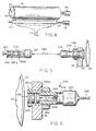
- FIGS. 5-7 Suitable means for guiding laser output to the surface of a imaging element are illustrated in FIGS. 5-7.
- FIG.5 shows a remote laser assembly that utilizes a fiber-optic cable to transmit laser pulses to the imaging element.
- a laser source 250 receives power via an electrical cable 252.
- Laser 250 is seated within the rear segment of a housing 255.
- Mounted within the forepart of housing are two or more focusing lenses 260a. 260b, which focus radiation emanating from laser 250 onto the end face of a fiber-optic cable 265, which is preferably (although not necessarily) secured within housing 255 by a removable retaining cap 267.
- Cable 265 conducts the output of laser 250 to an output assembly 270, which is illustrated in greater detail in FIG. 6.
- fiber-optic cable 265 enters the assembly 270 through a retaining cap 274 (which is preferably removable).
- Retaining cap 274 fits over a generally tubular body 276, which contains a series of threads 278.
- Mounted within the forepart of body 276 are two or more focusing lenses 280a, 280b, cable 265 is carried partway through body 276 by a sleeve 280.
- Body 276 defines a hollow channel between inner lens 280b and the terminus of sleeve 280, so the end face of cable 265 lies a selected distance A from inner lens 280b.
- the distance A and the focal lengths of lenses 280a, 280b are chosen so the at normal working distance from imaging element 55, the beam emanating from cable 265 will be precisely focused on the imaging elements surface. This distance can be altered to vary the size of an image feature.
- Body 276 can be secured to writing array 65 in any suitable manner.
- a nut 282 engages threads 278 and secures an outer flange 284 of body 276 against the outer face of writing array 65.
- the flange may, optionally, contain a transparent window 290 to protect the lenses from possible damage.
- the lens assembly may be mounted within the writing array on a pivot that permits rotation in the axial direction (i.e., with reference to FiG. 6, through the plane of the paper) to facilitate fine axial positioning adjustment. If the angle of rotation is kept to 4° or less, the circumferential error produced by the rotation can be corrected electronically by shifting the image data before it is transmitted to controller 80.
- FIG. 7 illustrates an alternative design in which the laser source irradiates the imaging elements surface directly, without transmission through fiber-optic cabling.
- laser source 250 is seated within the rear segment of an open housing 300.
- Mounted within the forepart of housing 300 are two or more focusing lenses 302a, 302b, which focus radiation emanating from laser 250 onto the surface of imaging element 55.
- the housing may, optionally, include a transparent window 305 mounted flush with the open end, and a heat sink 307.
- a suitable circuit for driving a diode-type (e.g., gallium arsenide) laser is illustrated schematically in FIG. 8. Operation of the circuit is governed by controller 80, which generates a fixed-pulse-width signal (preferably 5 to 20 ⁇ sec in duration) to a high-speed, high-current MOSFET driver 325.
- the output terminal of driver 325 is connected to the gate of a MOSFET 327. Because driver 325 is capable of supplying a high output current to quickly charge the MOSFET gate capacitance, the turn-on and turn-off times for MOSFET 327 are very short (preferably within 0.5 ⁇ sec) in spite of the capacitive load.
- the source terminal of MOSFET 327 is connected to ground potential.
- MOSFET 327 When MOSFET 327 is placed in a conducting state, current flows through and thereby activates a laser diode 330.
- a variable current-limiting resistor 332 is interposed between MOSFET 327 and laser diode 330 to allow adjustment of diode output. Such adjustment is useful, for example, to correct for different diode efficiencies and produce identical outputs in all lasers in the system, or to vary laser output as a means of controlling image size.
- a capacitor 334 is placed across the terminals of laser diode 330 to prevent damaging current overshoots,e.g., as a result of wire inductance combined with low laser-diode inter-electrode capacitance.
- a 0.2mm thick aluminium foil was degreased by immersing the foil in an aqueous solution containing 5g/l of sodium hydroxide at 50°C and rinsed with demineralised water.
- the foil was then electrochemically grained using an alternating current in an aqueous solution containing 4g/l of hydrochloric acid, 4 g/l of hydroboric acid and 0.5g/l of aluminium ions at a temperature of 35°C and a current density of 1200 A/m 2 to form a surface topography with an average center-line roughness R a of 0.5 ⁇ m.
- the aluminium foil was then etched with an aqueous solution containing 300g/l of sulfuric acid ate 60°C for 180 seconds and rinsed with demineralised water at 25°c for 30 seconds.
- the foil was subsequently subjected to anodic oxidation in an aqueous solution containing 200 g/l of sulfuric acid at at temperature of 45°c, a voltage of about 10V and a current density of 150 A/m 2 for about 300 seconds to form an anodic oxidation film of 3g/m 2 Al 2 O 3 , then washed with demineralised water, post treated with a solution containing 20 g/l of sodium bicarbonated at 40°C for 30s, subsequently rinsed with demineralised water of 20°C during 120s and dried.
- the obtained lithographic base was submersed in an aqueous solution containing 5% by weight of citric acid for 60s, rinsed with demineralised wter and dried at 40°C.
- An imaging element according to the invention was produced by preparing the following coating composition and coating it to the above described lithographic base in an amount of 30g/m 2 (wet coating amount) and drying it at 35°C.
- An imaging element as described above was subjected to a scanning Nd YLF infrared laser emitting at 1050nm (scan speed 4m/s, spot size 15 ⁇ m and 670mW power on the surface of the imaging element).
- the obtained image-wise exposed imaging element was mounted on an ABDIC 360TM offset printing press equipped with a VARN KOMPACTM II dampening system.
- ink VanSon RB2329TM and as a dampening liquid G671cTM (3% in water) commercially available from Agfa-Geveart NV were used.
- the press was started by allowing the print cylinder with the imaging element mounted thereon to rotate.
- the dampener rollers of the press were dropped on the imaging elements surface to as to supply dampening liquid to the imaging element and after 10 revolutions of the print cylinder, the ink rollers were dropped to supply ink. After a further 10 revolutions, clear prints were obtained with no ink uptake in the non-image parts.
- An imaging element was prepared as described in example 1 with the exception that the submersion of the lithographic base in a citric acid solution was omitted and the lithographic base was directly coated with the coating composition.
- a printing plate was prepared as in example 1 and after a total of 20 revolutions of the print cylinder, clear prints were obtained without ink uptake in the non-image areas.
- the obtained dispersion was coated on a polyethyleneterephthalate film support (coated with a hydrophilic adhesion layer) to a wet coating thickness of 50 g/m 2 , dried at 30 °C. and subsequently hardened by subjecting it to a temperature of 57 °C for 1 week.
- An imaging element using the above described lithographic base and printing plate therefrom were then prepared as described in example 1. After 20 revolutions, clear prints without ink uptake in the non-image areas were obtained.
Abstract
- (1) image-wise exposing to light an imaging element comprising (i) on a hydrophilic surface of a lithographic base an image forming layer comprising hydrophobic thermoplastic polymer particles dispersed in a hydrophilic binder and (ii) a compound capable of converting light to heat, said compound being comprised in said image forming layer or a layer adjacent thereto;
- (2) and developing a thus obtained image-wise exposed imaging element by mounting it on a print cylinder of a printing press and supplying an aqueous dampening liquid and/or ink to said image forming layer while rotating said print cylinder.
Description
- The present invention relates to a method for making a lithographic printing plate. More in particular, the present invention relates to a method wherein the lithographic printing plate is developed on the printing press subsequent to image-wise exposure.
- Lithography is the process of printing from specially prepared surfaces, some areas of which are capable of accepting lithographic ink, whereas other areas, when moistened with water, will not accept the ink. The areas which accept ink form the printing image areas and the ink-rejecting areas form the background areas.
- In the art of photolithography, a photographic material is made imagewise receptive to oily or greasy inks in the photo-exposed (negative-working) or in the non-exposed areas (positive-working) on a hydrophilic background.
- In the production of common lithographic printing plates, also called surface litho plates or planographic printing plates, a support that has affinity to water or obtains such affinity by chemical treatment is coated with a thin layer of a photosensitive composition. Coatings for that purpose include light-sensitive polymer layers containing diazo compounds, dichromate-sensitized hydrophilic colloids and a large variety of synthetic photopolymers. Particularly diazo-sensitised systems are widely used.
- Upon image-wise exposure of the light-sensitive layer the exposed image areas become insoluble and the unexposed areas remain soluble. The plate is then developed with a suitable liquid to remove the diazonium salt or diazo resin in the unexposed areas.
- Commercially available diazo based printing plates most commonly use an anodised and roughened aluminium as a support having a hydrophilic surface. However, commercial plates are also available that use a flexible support such as paper provided with a hydrophilic layer. For example, Lithocraft 10008 FOTOPLATE™ is a diazo based printing plate that comprises on a paper support a hydrophilic layer on top of which is provided a diazo based photosensitive layer. According to plate instructions of the supplier, a plate can be prepared by image-wise exposure of the lithographic printing plate precursor or imaging element, mounting the exposed imaging element on the press and wiping its surface with Lithocraft® 10008 Developer Desensitiser. The plate instructions also contemplate a method wherein no developer desensitizer is used. However, such method most often results in poor lithographic preformance so that in practice a Developer Desensitiser is almost always needed.
- A particular disadvantage of photosensitive imaging elements such as described above for making a printing plate is that they have to be shielded from the light. This is a particular disadvantage if on press development is contemplated since mounting the image-wise exposed imaging element is generally done in normal daylight so that the handling time for mounting the imaging element is limited. Moreover, diazo based aluminium type printing plates are completely unsuitable for on press development.
- On the other hand, methods are known for making printing plates involving the use of imaging elements that are heat sensitive rather than photosensitive. For example, Research Disclosure no. 33303 of January 1992 discloses a heat sensitive imaging element comprising on a support a cross-linked hydrophilic layer containing thermoplastic polymer particles and an infrared absorbing pigment such as e.g. carbon black. By image-wise exposure to an Infrared laser, the thermoplastic polymer particles are image-wise coagulated thereby rendering the surface of the imaging element and these areas ink acceptant without any further development. A disadvantage of this method is that the printing plate obtained is easily damaged since the non-printing areas may become ink accepting when some pressure is applied thereto. Moreover, under critical conditions, the lithographic performance of such a printing plate may be poor and accordingly such printing plate has little lithographic printing latitude.
- It is an object of the present invention to provide a method for making a printing plate having excellent printing properties in a convenient an environmental friendly way.
- Further objects of the present invention will become clear from the description hereinafter.
- According to the present invention there is provided a method for making a lithographic printing plate comprising the steps of:
- (1) image-wise exposing to light an imaging element comprising (i) on a hydrophilic surface of a lithographic base an image forming layer comprising hydrophobic thermoplastic polymer particles dispersed in a hydrophilic binder and (ii) a compound capable of converting light to heat, said compound being comprised in said image forming layer or a layer adjacent thereto;
- (2) and developing a thus obtained image-wise exposed imaging element by mounting it on a print cylinder of a printing press and supplying an aqueous dampening liquid and/or ink to said image forming layer while rotating said print cylinder.
- The present invention further provides a method for making multiple copies of an orginal image comprising the steps of:
- (1) image-wise exposing to light an imaging element comprising (i) on a hydrophilic surface of a lithographic base an image forming layer comprising hydrophobic thermoplastic polymer particles dispersed in a hydrophilic binder and (ii) a compound capable of converting light to heat, said compound being comprised in said image forming layer or a layer adjacent thereto;
- (2) mounting a thus obtained image-wise exposed imaging element without development, on a print cylinder of a printing press;
- (3) rotating said print cylinder while supplying an aqueous dampening liquid and/or supplying ink to said image forming layer of said imaging element and
- (4) transfering ink from said imaging element to a receiving element which is generally a paper sheet.
- The present invention further relates to a method for making a lithographic printing plate comprising the steps of:
- (1) mounting an imaging element comprising (i) on a hydrophilic surface of a lithographic base an image forming layer comprising hydrophobic thermoplastic polymer particles dispersed in a hydrophilic binder and (ii) a compound capable of converting light to heat, said compound being comprised in said image forming layer or a layer adjacent thereto on a print cylinder of a printing press;
- (2) image-wise exposing said imaging element by means of a laser or LED;
- (3) and developing a thus obtained image-wise exposed imaging element by supplying an aqueous dampening liquid and/or ink to said image forming layer while rotating said print cylinder.
- The present invention also discloses a method for making multiple copies from an original comprising the steps of:
- (1) mounting an imaging element comprising (i) on a hydrophilic surface of a lithographic base an image forming layer comprising hydrophobic thermoplastic polymer particles dispersed in a hydrophilic binder and (ii) a compound capable of converting light to heat, said compound being comprised in said image forming layer or a layer adjacent thereto on a print cylinder of a printing press;
- (2) image-wise exposing said imaging element by means of a laser or LED;
- (3) developing a thus obtained image-wise exposed imaging element by supplying an aqueous dampening liquid and/or ink to said image forming layer while rotating said print cylinder;
- (4) transfering ink from said imaging element to a receiving element.
- The present invention also describes a printing apparatus comprising:
- (i) at least one print station including:
- a print cylinder;
- means for mounting to the print cylinder an imaging element;
- at least one laser or L.E.D device;
- means for guiding output of said laser or L.E.D. device to focus on the imaging elements surface;
- means for moving the guiding means and support means relative to one another to effect a scan of the imaging elements surface by the output of said laser or L.E.D. device;
- (ii) means for supplying a dampening liquid to said print cylinder;
- (iii) means for supplying ink to said print cylinder;
- (iv) means for transferring a receiving element to said print station;
- (v) means for transferring ink from said print cylinder to said receiving element.
- In a still further aspect, the present invention relates to a method for making a lithographic printing plate comprising the steps of:
- (1) image-wise exposing to light an imaging element comprising (i) on a hydrophilic surface of a lithographic base an image forming layer comprising hydrophobic thermoplastic polymer particles dispersed in a hydrophilic binder and (ii) a compound capable of converting light to heat, said compound being comprised in said image forming layer or a layer adjacent;
- (2) and developing a thus obtained image-wise exposed imaging element by rinsing it with plain water.
- The present invention is illustrated by way of reference to the following drawings without however the intention to limit the invention thereto:
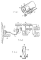
- FIG. 1 is an isometric view of the cylindrical embodiment of an imaging apparatus suitable for use in accordance with the present invention, and which operates in conjunction with a diagonal-array writing array;
- FIG. 2 is a schematic depiction of the embodiment shown in FIG. 1, and which illustrates in greater detail its mechanism of operation;
- FIG. 3 is a front-end view of a writing array for imaging in accordance with the present invention, and in which imaging elements are arranged in a diagonal array;
- FIG. 4 is an isometric view of the cylindrical embodiment of an imaging apparatus suitable for use in accordance with the present invention, and which operates in conjunction with a linear-array writing array;
- FIG. 5 is a cut-away view of a remote laser and beam-guiding system;
- FIG. 6 is an enlarged, partial cut-away view of a lens element for focusing a laser beam from an optical fiber onto the surface of an imaging element;
- FIG. 7 is an enlarged, cut-away view of a lens element having an integral laser and;
- FIG. 8 is a schematic circuit diagram of a laser-driver circuit suitable for use with the present invention.
- An imaging element for use in accordance with the present invention comprises on a hydrophilic surface of a lithographic base an image forming layer comprising hydrophobic thermoplastic polymer particles dispersed in a hydrophilic binder. The hydrophilic binder used in connection with the present invention is perferably not cross-linked or only sightly cross-linked. The imaging element further includes a compound capable of converting light to heat. This compound is preferably comprised in the image forming layer but can also be provided in a layer adjacent to the image forming layer.
- According to one embodiment of the present invention, the lithographic base can be an anodised aluminium. A particularly preferred lithographic base is an electrochemically grained and anodised aluminium support. According to the present invention, an anodised aluminium support may be treated to improve the hydrophilic properties of its surface. For example, the aluminium support may be silicated by treating its surface with sodium silicate solution at elevated temperature, e.g. 95°C. Alternatively, a phosphate treatment may be applied which involves treating the aluminium oxide surface with a phosphate solution that may further contain an inorganic fluoride. Further, the aluminium oxide surface may be rinsed with a citric acid or citrate solution. This treatment may be carried out at room temperature or can be carried out at a slightly elevated temperature of about 30 to 50°C. A further interesting treatment involves rinsing the aluminium oxide surface with a bicarbonate solution. It is further evident that one or more of these post treatments may be carried out alone or in combination.
- According to another embodiment in connection with the present invention, the lithographic base comprises a flexible support, such as e.g. paper or plastic film, provided with a cross-linked hydrophilic layer. A particularly suitable cross-linked hydrophilic layer may be obtained from a hydrophilic binder cross-linked with a cross-linking agent such as formaldehyde, glyoxal, polyisocyanate or a hydrolysed tetra-alkylorthosilicate. The latter is particularly preferred.
- As hydrophilic binder there may be used hydrophilic (co)polymers such as for example, homopolymers and copolymers of vinyl alcohol, acrylamide, methylol acrylamide, methylol methacrylamide, acrylic acid, methacrylic acid, hydroxyethyl acrylate, hydroxyethyl methacrylate or maleic anhydride/vinylmethylether copolymers. The hydrophilicity of the (co)polymer or (co)polymer mixture used is preferably the same as or higher than the hydrophilicity of polyvinyl acetate hydrolyzed to at least an extent of 60 percent by weight, preferably 80 percent by weight.
- The amount of crosslinking agent, in particular of tetraalkyl orthosilicate, is preferably at least 0.2 parts by weight per part by weight of hydrophilic binder, preferably between 0.5 and 5 parts by weight, more preferably between 1.0 parts by weight and 3 parts by weight.
- A cross-linked hydrophilic layer in a lithographic base used in accordance with the present embodiment preferably also contains substances that increase the mechanical strength and the porosity of the layer. For this purpose colloidal silica may be used. The colloidal silica employed may be in the form of any commercially available water-dispersion of colloidal silica for example having an average particle size up to 40 nm, e.g. 20 nm. In addition inert particles of larger size than the colloidal silica can be added e.g. silica prepared according to Stöber as described in J. Colloid and Interface Sci., Vol. 26, 1968, pages 62 to 69 or alumina particles or particles having an average diameter of at least 100 nm which are particles of titanium dioxide or other heavy metal oxides. By incorporating these particles the surface of the cross-linked hydrophilic layer is given a uniform rough texture consisting of microscopic hills and valleys, which serve as storage places for water in background areas.
- The thickness of a cross-linked hydrophilic layer in a lithographic base in accordance with this embodiment may vary in the range of 0.2 to 25 µm and is preferably 1 to 10 µm.
- Particular examples of suitable cross-linked hydrophilic layers for use in accordance with the present invention are disclosed in EP-A 601240, GB-P-1419512, FR-P-2300354, US-P-3971660, US-P-4284705 and EP-A 514490.
- As flexible support of a lithographic base in connection with the present embodiment it is particularly preferred to use a plastic film e.g. substrated polyethylene terephthalate film, cellulose acetate film, polystyrene film, polycarbonate film etc... The plastic film support may be opaque or transparent.
- It is particularly preferred to use a polyester film support to which an adhesion improving layer has been provided. Particularly suitable adhesion improving layers for use in accordance with the present invention comprise a hydrophilic binder and colloidal silica as disclosed in EP-A 619524, EP-A 620502 and EP-A 619525. Preferably, the amount of silica in the adhesion improving layer is 200 mg per m2 and 750 mg per m2. Further, the ratio of silica to hydrophilic binder is preferably more than 1 and the surface area of the colloidal silica is preferably at least 300 m2 per gram, more preferably a surface area of 500 m2 per gram.
- In accordance with the present invention, on top of a hydrophilic surface there is provided an image forming layer. Optionally, there may be provided one or more intermediate layers between the lithographic base and the image forming layer. An image forming layer in connection with the present invention comprises thermoplastic polymer particles dispersed in a hydrophilic binder.
- Suitable hydrophilic binders for use in an image forming layer in connection with this invention are for example synthetic homo or copolymers such as a polyvinylalcohol, a poly(meth)acrylic acid, a poly(meth)acrylamide, a polyhydroxyethyl(meth)acrylate, a polyvinylmethylether or natural binders such as gelatin, a polysacharide such as e.g. dextran, pullulan, cellulose, arabic gum, alginic acid.
- Hydrophobic thermoplastic polymer particles used in connection with the present invention preferably have a coagulation temperature above 35°C and more preferably above 50°C. Coagulation may result from softening or melting of the thermoplastic polymer particles under the influence of heat. There is no specific upper limit to the coagulation temperature of the thermoplastic hydrophobic polymer particles, however the temperature should be sufficiently below the decomposition of the polymer particles. Preferably the coagulation temperature is at least 10°C below the temperature at which the decomposition of the polymer particles occurs. When said polymer particles are subjected to a temperature above coagulation temperature they coagulate to form a hydrophobic agglomerate in the hydrophilic layer so that at these parts the hydrophilic layer becomes insoluble in plain water or an aqueous liquid.
- Specific examples of hydrophobic polymer particles for use in connection with the present invention are e.g. polyethylene, polyvinyl chloride, polymethyl (meth)acrylate, polyethyl (meth)acrylate, polyvinylidene chloride, polyacrylonitrile, polyvinyl carbazole etc. or copolymers thereof. Most preferably used is polyethylene.
- The weight average molecular weight of the polymers may range from 5,000 to 1,000,000g/mol.
- The hydrophobic particles may have a particle size from 0.01µm to 50µm, more preferably between 0.05mm and 10mm and most preferably between 0.05µm and 2µm.
- The polymer particles are present as a dispersion in the aqueous coating liquid of the image forming layer and may be prepared by the methods disclosed in US-P-3.476.937. Another method especially suitable for preparing an aqueous dispersion of the thermoplastic polymer particles comprises:
- dissolving the hydrophobic thermoplastic polymer in an organic water immiscible solvent,
- dispersing the thus obtained solution in water or in an aqueous medium and
- removing the organic solvent by evaporation.
- The amount of hydrophobic thermoplastic polymer particles contained in the image forming layer is preferably between 20% by weight and 65% by weight and more preferably between 25% by weight and 55% by weight and most preferably between 30% by weight and 45% by weight.
- Suitable compounds capable of converting light into heat are preferably infrared absorbing components although the wavelength of absorption is not of particular importance as long as the absorption of the compound used is in the wavelength range of the light source used for image-wise exposure. Particularly useful compounds are for example dyes and in particular infrared dyes, carbon black, metal carbides, borides, nitrides, carbonitrides, bronze-structured oxides and oxides structurally related to the bronze family but lacking the A component e.g. WO2.9. It is also possible to use conductive polymer dispersion such as polypyrrole or polyaniline-based conductive polymer dispersions. The lithographic performance and in particular the print endurance obtained depends on the heat-sensitivity of the imaging element. In this respect it has been found that carbon black yields very good and favorable results.
- A light to heat converting compound in connection with the present invention is most preferably added to the image forming layer but at least part of the light to heat converting compound may also be comprised in a neighbouring layer. Such layer can be for example the cross-linked hydrophilic layer of a lithographic base according to the second embodiment of lithographic bases explained above.
- In accordance with a method of the present invention for obtaining a printing plate, the imaging element is image-wise exposed and subsequently is mounted on a print cylinder of a printing press. According to a preferred embodiment, the printing press is then started and while the print cylinder with the imaging element mounted thereon rotates, the dampener rollers that supply dampening liquid are dropped on the imaging element and subsequent thereto the ink rollers are dropped. Generally, after about 10 revolutions of the print cylinder the first clear and useful prints are obtained.
- According to an alternative method, the ink rollers and dampener rollers may be dropped simultaneously or the ink rollers may be dropped first.
- Suitable dampening liquids that can be used in connection with the present invention are aqueous liquids generally having an acidic pH and comprising an alcohol such as isopropanol. With regard to dampening liquids useful in the present invention, there is no particular limitation and commercially available dampening liquids, also known as fountain solutions, can be used.
- It may be advantageous to wipe the image forming layer of an image-wise exposed imaging element with e.g. a cotton pad or sponge soaked with water before mounting the imaging element on the press or at least before the printing press starts running. This will remove some non-image areas but will not actually develop the imaging element. However, it has the advantage that possible substantial contamination of the dampening system of the press and ink used is avoided.
- According to an alternative method, the imaging element is first mounted on the print cylinder of the printing press and then image-wise exposed directly on the press. Subsequent to exposure, the imaging element can be developed as described above.
- According to a still further method in connection with the present invention, the imaging element may be image-wise exposed and subsequently developed by rinsing it with plain water.
- Image-wise exposure in connection with the present invention is preferably an image-wise scanning exposure involving the use of a laser or L.E.D.. It is highly preferred in connection with the present invention to use a laser emitting in the infrared (IR) and/or near-infrared, i.e. emitting in the wavelength range 700-1500nm. Particularly preferred for use in connection with the present invention are laser diodes emitting in the near-infrared.
- A preferred imaging apparatus suitable for image-wise scanning exposure in accordance with the present invention preferably includes a laser output that can be provided directly to the imaging elements surface via lenses or other beam-guiding components, or transmitted to the surface of a blank imaging element from a remotely sited laser using a fiber-optic cable. A controller and associated positioning hardware maintains the beam output at a precise orientation with respect to the imaging elements surface, scans the output over the surface, and activates the laser at positions adjacent selected points or areas of the imaging element. The controller responds to incoming image signals corresponding to the original document and/or picture being copied onto the imaging element to produce a precise negative or positive image of that original. The image signals are stored as a bitmap data file on a computer. Such files may be generated by a raster image processor (RIP) or other suitable means. For example, a RIP can accept Input data in page-description language, which defines all of the features required to be transferred onto the imaging element, or as a combination of page-description language and one or more image data files. The bitmaps are constructed to define the hue of the color as well as screen frequencies and angles in case of amplitude modulation screening. However, the present invention is particularly suitable for use in combination with frequency modulation screening as disclosed in e.g. EP-A 571010, EP-A 620677 and EP-A 620674.
- The imaging apparatus can operate on its own, functioning solely as a platemaker, or can be incorporated directly into a lithographic printing press having means for supplying a dampening liquid. In the latter case, printing may commence immediately after image-wise exposure and development, thereby reducing press set-up time considerably. The imaging apparatus can be configured as a flatbed recorder or as a drum recorder, with the lithographic plate blank mounted to the interior or exterior cylindrical surface of the drum. Obviously, the exterior drum design is more appropriate to use in situ, on a lithographic press, in which case the print cylinder itself constitutes the drum component of the recorder or plotter.
- In a preferred drum configuration, the requisite relative motion between the laser beam and the imaging element is achieved by rotating the drum(and the imaging element mounted thereon) about its axis and moving the beam parallel to the rotation axis, thereby scanning the imaging element circumferentially so the image "grows" in the axial direction. Alternatively, the beam can move parallel to the drum axis and, after each pass across the imaging element, increment angularly so that the image on the imaging element "grows" circumferentially. In both cases, after a complete scan by the beam and development, an image corresponding to the original will have been applied to the surface of the imaging element. In the flatbed configuration, the beam is drawn across either axis of the imaging element, and is indexed along the other axis after each pass. Of course, the requisite relative motion between the beam and the imaging element may be produced by movement of the imaging element rather than (or in addition to) movement of the beam.
- Regardless of the manner in which the beam is scanned, it is generally preferable (for reasons of speed) to employ a plurality of lasers and guide their outputs to a single writing array. The writing array is then indexed, after completion of each pass across or along the imaging element, a distance determined by the number of beams emanating from the array, and by the desired resolution (i.e. the number of image points per unit length.
- The following describes in more detail a preferred embodiment of an imaging apparatus suitable for use in connection with the present invention.
- Refer first to FIG. 1 of the drawings, which illustrates an exterior drum embodiment of an imaging system suitable for use in connection with the present invention. The assembly includes a
cylinder 50 around which is wrapped animaging element 55.Cylinder 50 includes avoid segment 60, within which the outside margins ofimaging element 55 are secured by conventional clamping means (not shown). The size of the void segment can vary greatly depending on the environment in whichcylinder 50 is employed. - Desirably,
cylinder 50 is straight forwardly incorporated into the design of a conventional lithographic press having means for supplying dampening liquid to the imaging element, and serves as the print cylinder of the press. In a typical pressconstructions imaging element 55 receives ink and dampening liquid from an ink train and a sequence of dampening cylinders respectively, whose terminal cylinders are in rolling engagement withcylinder 50. The latter cylinder also rotates in contact with a blanket cylinder, which transfers ink to the receiving element which is generally a paper sheet. The press may have more than one such printing assembly arranged in a linear array. Alternatively, a plurality of assemblies may be arranged about a large central impression cylinder in rolling engagement with all of the blanket cylinders. -
Cylinder 50 is supported in a frame and rotated by a standard electric motor or other conventional means (illustrated schematically in FIG. 2). The angular position ofcylinder 50 is monitored by a shaft encoder (see FIG. 4). A writingarray 65, mounted for movement on alead screw 67 and aguide bar 69, traversesimaging element 55 as it rotates. Axial movement of writingarray 65 results from rotation of astepper motor 72, which turnslead screw 67 and thereby shifts the axial position of writingarray 65.Stepper motor 72 is activated during thetime writing array 65 is positioned overvoid 60, after writingarray 65 has passed over the entire surface ofimaging element 55. The rotation ofstepper motor 72shifts writing array 65 to the appropriate axial location to begin the next imaging pass. - The axial index distance between successive imaging passes is determined by the number of imaging objects in writing
array 65 and their configuration therein, as well as by the desired resolution. As shown in FIG. 2, a series of laser sources L1, L2, L3, ... Ln, driven by suitable laser drivers collectively designated byreference numeral 75, each provide output to a fiber-optic cable. The lasers are preferably gallium-arsenide models, although any other lasers can be used. - The cables that carry laser output are collected into a
bundle 77 and emerge separately into writingarray 65. It may prove desirable, in order to conserve power, to maintain the bundle in a configuration that does not require bending above the fiber's critical angle of refraction (thereby maintaining total internal reflection). - Also as shown in Fig. 2, a
controller 80 actuateslaser drivers 75 when the associated lasers reach appropriate points oppositeimaging element 55, and in addition operatesstepper motor 72 and thecylinder drive motor 82. -
Controller 80 receives data from two sources. The angular position ofcylinder 50 with respect to writingarray 65 is constantly monitored by adetector 85, which provides signals indicative of that position tocontroller 80. In addition, an image data source (e.g., a computer) also provides data signals tocontroller 80. The image data define points onimaging element 55 where image spots are to be written.Controller 80, therefore, correlates the instantaneous relative positions of writingarray 65 and imaging element 55 (as reported by detector 85) with the image data to actuate the appropriate laser drivers at the appropriate times during scan ofimaging element 55. The control circuitry required to implement this scheme is well-known in the scanner and plotter art. - The laser output cables terminate in
lens assemblies 96, mounted within writingarray 65, that preferably precisely focus the beams onto the surface ofimaging element 55. A suitable lens-assembly design is described below, for purposes of the present discussion, these assemblies are generically indicated byreference numeral 96. A suitable configuration is illustrated in FIG. 3 in this arrangement,lens assemblies 96 are staggered across the face ofbody 65. - The staggered lens design facilitates use of a greater number of lens assemblies in a single head than would be possible with a linear arrangement. And since imaging time depends directly on the number of lens elements, a staggered design offers the possibility of faster overall imaging.
Controller 80 either receives image data already arranged into vertical columns, each corresponding to a different lens assembly or can progressively sample, in columnar fashion,the contents of a memory buffer containing a complete bitmap representation of the image to be transferred. In either case,controller 80 recognizes the different relative positions of the lens assemblies with respect toimaging element 55 and actuates the appropriate laser only when its associated lens assembly is positioned over a point to be imaged. - An alternative array design is illustrated in FIG. 4, which also shows the
detector 85 mounted to thecylinder 50. In this case the writing array, designated byreference numeral 150, comprises a long linear body fed by fiber-optic cables drawn frombundle 77. The interior of writingarray 150, or some portion thereof, contains threads that engagelead screw 67, rotation of which advances writingarray 150 alongimaging element 55 as discussed previously.Individual lens assemblies 96 are evenly spaced a distance B from one another. Distance B corresponds to the difference between the axial length ofplate 55 and the distance between the first and last lens assembly; it represents the total axial distance traversed by writingarray 150 during the course of a complete scan. Eachtime writing array 150 encounters void 60,stepper motor 72 rotates to advance writingarray 150 an axial distance equal to the desired distance between imaging passes (i.e., the print density). This distance is smaller by a factor of n than the distance indexed by the previously described embodiment (writing array 65), where n is the number of lens assemblies included in writingarray 65. - Suitable means for guiding laser output to the surface of a imaging element are illustrated in FIGS. 5-7. Refer first to FIG.5, which shows a remote laser assembly that utilizes a fiber-optic cable to transmit laser pulses to the imaging element. In this arrangement a
laser source 250 receives power via anelectrical cable 252.Laser 250 is seated within the rear segment of ahousing 255. Mounted within the forepart of housing are two or more focusing lenses 260a. 260b, which focus radiation emanating fromlaser 250 onto the end face of a fiber-optic cable 265, which is preferably (although not necessarily) secured withinhousing 255 by aremovable retaining cap 267.Cable 265 conducts the output oflaser 250 to anoutput assembly 270, which is illustrated in greater detail in FIG. 6. - With reference to that figure, fiber-
optic cable 265 enters theassembly 270 through a retaining cap 274 (which is preferably removable). Retainingcap 274 fits over a generallytubular body 276, which contains a series ofthreads 278. Mounted within the forepart ofbody 276 are two or more focusinglenses 280a, 280b,cable 265 is carried partway throughbody 276 by asleeve 280.Body 276 defines a hollow channel betweeninner lens 280b and the terminus ofsleeve 280, so the end face ofcable 265 lies a selected distance A frominner lens 280b. The distance A and the focal lengths oflenses 280a, 280b are chosen so the at normal working distance fromimaging element 55, the beam emanating fromcable 265 will be precisely focused on the imaging elements surface. This distance can be altered to vary the size of an image feature. -
Body 276 can be secured to writingarray 65 in any suitable manner. In the illustrated embodiments anut 282 engagesthreads 278 and secures anouter flange 284 ofbody 276 against the outer face of writingarray 65. The flange may, optionally, contain atransparent window 290 to protect the lenses from possible damage. - Alternatively, the lens assembly may be mounted within the writing array on a pivot that permits rotation in the axial direction (i.e., with reference to FiG. 6, through the plane of the paper) to facilitate fine axial positioning adjustment. If the angle of rotation is kept to 4° or less, the circumferential error produced by the rotation can be corrected electronically by shifting the image data before it is transmitted to
controller 80. - Refer now to FIG. 7, which illustrates an alternative design in which the laser source irradiates the imaging elements surface directly, without transmission through fiber-optic cabling. As shown in the figure,
laser source 250 is seated within the rear segment of anopen housing 300. Mounted within the forepart ofhousing 300 are two or more focusinglenses 302a, 302b, which focus radiation emanating fromlaser 250 onto the surface ofimaging element 55. The housing may, optionally, include atransparent window 305 mounted flush with the open end, and aheat sink 307. - It should be understood that while the preceding discussion of imaging configurations and the accompanying figures have assumed the use of optical fibers, in each case the fibers can be eliminated through use of the embodiment shown in FIG. 7.
- A suitable circuit for driving a diode-type (e.g., gallium arsenide) laser is illustrated schematically in FIG. 8. Operation of the circuit is governed by
controller 80, which generates a fixed-pulse-width signal (preferably 5 to 20 µsec in duration) to a high-speed, high-current MOSFET driver 325. The output terminal ofdriver 325 is connected to the gate of aMOSFET 327. Becausedriver 325 is capable of supplying a high output current to quickly charge the MOSFET gate capacitance, the turn-on and turn-off times forMOSFET 327 are very short (preferably within 0.5 µsec) in spite of the capacitive load. The source terminal ofMOSFET 327 is connected to ground potential. - When
MOSFET 327 is placed in a conducting state, current flows through and thereby activates alaser diode 330. A variable current-limitingresistor 332 is interposed betweenMOSFET 327 andlaser diode 330 to allow adjustment of diode output. Such adjustment is useful, for example, to correct for different diode efficiencies and produce identical outputs in all lasers in the system, or to vary laser output as a means of controlling image size. - A
capacitor 334 is placed across the terminals oflaser diode 330 to prevent damaging current overshoots,e.g., as a result of wire inductance combined with low laser-diode inter-electrode capacitance. - The present invention will be further illustrated by way of the following examples, without however the intention to limit the invention thereto. All parts are by weight unless otherwise specified.
- A 0.2mm thick aluminium foil was degreased by immersing the foil in an aqueous solution containing 5g/l of sodium hydroxide at 50°C and rinsed with demineralised water. The foil was then electrochemically grained using an alternating current in an aqueous solution containing 4g/l of hydrochloric acid, 4 g/l of hydroboric acid and 0.5g/l of aluminium ions at a temperature of 35°C and a current density of 1200 A/m2 to form a surface topography with an average center-line roughness Ra of 0.5µm.
- After rinsing with demineralised water the aluminium foil was then etched with an aqueous solution containing 300g/l of sulfuric acid ate 60°C for 180 seconds and rinsed with demineralised water at 25°c for 30 seconds.
- The foil was subsequently subjected to anodic oxidation in an aqueous solution containing 200 g/l of sulfuric acid at at temperature of 45°c, a voltage of about 10V and a current density of 150 A/m2 for about 300 seconds to form an anodic oxidation film of 3g/m2 Al2O3, then washed with demineralised water, post treated with a solution containing 20 g/l of sodium bicarbonated at 40°C for 30s, subsequently rinsed with demineralised water of 20°C during 120s and dried.
- The obtained lithographic base was submersed in an aqueous solution containing 5% by weight of citric acid for 60s, rinsed with demineralised wter and dried at 40°C.
- An imaging element according to the invention was produced by preparing the following coating composition and coating it to the above described lithographic base in an amount of 30g/m2 (wet coating amount) and drying it at 35°C.
- To 6.75g of a 20% dispersion of polymethylmethacrylate (average particle diameter of 90nm) stabilised with Hostapal B (1% vs. polymer) in deionised water was subsequently added, 7g of a 15% dispersion of carbon black and 1ml of a solution of a wetting agent in water, 73g water and finally while stirring, 12g of a 5% solution of a 98% hydrolysed polyvinylacetate having a weight average molecular weight of 200.000 g/mol in water is added.
- An imaging element as described above was subjected to a scanning Nd YLF infrared laser emitting at 1050nm (scan speed 4m/s, spot size 15µm and 670mW power on the surface of the imaging element).
- The obtained image-wise exposed imaging element was mounted on an ABDIC 360™ offset printing press equipped with a VARN KOMPAC™ II dampening system. As ink, VanSon RB2329™ and as a dampening liquid G671c™ (3% in water) commercially available from Agfa-Geveart NV were used.
- Subsequent to mounting the imaging element, the press was started by allowing the print cylinder with the imaging element mounted thereon to rotate. The dampener rollers of the press were dropped on the imaging elements surface to as to supply dampening liquid to the imaging element and after 10 revolutions of the print cylinder, the ink rollers were dropped to supply ink. After a further 10 revolutions, clear prints were obtained with no ink uptake in the non-image parts.
- An imaging element was prepared as described in example 1 with the exception that the submersion of the lithographic base in a citric acid solution was omitted and the lithographic base was directly coated with the coating composition.
- A printing plate was prepared as in example 1 and after a total of 20 revolutions of the print cylinder, clear prints were obtained without ink uptake in the non-image areas.
- To 398 g of a dispersion contg. 21.5% TiO2 (average particle size 0.3 to 0.5 µm) and 2.5% polyvinyl alcohol in deionized water were subsequently added, while stirring, 195 g of a hydrolyzed 22% tetramethylorthosilicate emulsion in water and 12 g of a 10% solution of a wetting agent.
- To this mixture was added 395 g of deionized water and the pH was adjusted to pH=4.
- The obtained dispersion was coated on a polyethyleneterephthalate film support (coated with a hydrophilic adhesion layer) to a wet coating thickness of 50 g/m2, dried at 30 °C. and subsequently hardened by subjecting it to a temperature of 57 °C for 1 week.
- An imaging element using the above described lithographic base and printing plate therefrom were then prepared as described in example 1. After 20 revolutions, clear prints without ink uptake in the non-image areas were obtained.
Claims (9)
- A method for making a lithographic printing plate comprising the steps of:(1) image-wise exposing to light an imaging element comprising (i) on a hydrophilic surface of a lithographic base an image forming layer comprising hydrophobic thermoplastic polymer particles dispersed in a hydrophilic binder and (ii) a compound capable of converting light to heat, said compound being comprised in said image forming layer or a layer adjacent thereto;(2) and developing a thus obtained image-wise exposed imaging element by mounting it on a print cylinder of a printing press and supplying an aqueous dampening liquid and/or ink to said image forming layer while rotating said print cylinder.
- A method according to claim 1 wherein said compound capable of converting light to heat is selected from the group consisting of an infrared absorbing dye, carbon black, a metal boride, a metal carbide, a metal nitride, a metal carbonitride and a conductive polymer particle.
- A method according to any of the above claims wherein image-wise exposure is carried out by means of a laser, a LED or a plurality of lasers.
- A method according to any of the above claims wherein said compound capable of converting light to heat is comprised in said image forming layer.
- A method according to any of the above claims wherein said lithographic base is an anodised aluminium or comprises a flexible support having thereon a cross-linked hydrophilic layer.
- A method according to any of the above claims wherein said thermoplastic polymer particles have a coagulation temperature of at least 35°C.
- A method according to any of the above claims wherein said hydrophilic binder in said image forming layer is selected from the group consisting of a polyvinylalcohol, a poly(meth)acrylic acid, a poly(meth)acrylamide, a polyhydroxyethyl(meth)acrylate, a polyvinylmethylether, a polysacharide.
- A method according to any of the above claims wherein said hydrophobic thermoplastic polymer particles are selected from the group consisting of polyethylene, polystyrene, polymethyl(meth)acrylate, polyvinylchloride, polyethyl(meth)acrylate, polyvinylidenechloride, polyacrylonitrile and polyvinylcarbazole.
- A method for making multiple copies of an orginal image comprising the steps of:(1) image-wise exposing to light an imaging element comprising (i) on a hydrophilic surface of a lithographic base an image forming layer comprising hydrophobic thermoplastic polymer particles dispersed in a hydrophilic binder and (ii) a compound capable of converting light to heat, said compound being comprised in said image forming layer or a layer adjacent thereto;(2) mounting a thus obtained image-wise exposed imaging element without development, on a print cylinder of a printing press;(3) rotating said print cylinder while supplying an aqueous dampening liquid and/or supplying ink to said image forming layer of said imaging element and(4) transfering ink from said imaging element to a receiving element.
Priority Applications (5)
| Application Number | Priority Date | Filing Date | Title |
|---|---|---|---|
| EP19950202874 EP0770494B1 (en) | 1995-10-24 | 1995-10-24 | A method for making a lithographic printing plate involving on press development |
| DE1995617174 DE69517174T2 (en) | 1995-10-24 | 1995-10-24 | Process for the production of a lithographic printing plate with development taking place on the printing press |
| US08/715,496 US6030750A (en) | 1995-10-24 | 1996-09-18 | Method for making a lithographic printing plate involving on press development |
| JP29790196A JP2938397B2 (en) | 1995-10-24 | 1996-10-23 | Method for producing a lithographic printing plate including on-press development |
| US09/440,165 US6096481A (en) | 1995-10-24 | 1999-11-15 | Method for making a lithographic printing plate involving on press development |
Applications Claiming Priority (1)
| Application Number | Priority Date | Filing Date | Title |
|---|---|---|---|
| EP19950202874 EP0770494B1 (en) | 1995-10-24 | 1995-10-24 | A method for making a lithographic printing plate involving on press development |
Publications (3)
| Publication Number | Publication Date |
|---|---|
| EP0770494A2 true EP0770494A2 (en) | 1997-05-02 |
| EP0770494A3 EP0770494A3 (en) | 1997-05-07 |
| EP0770494B1 EP0770494B1 (en) | 2000-05-24 |
Family
ID=8220761
Family Applications (1)
| Application Number | Title | Priority Date | Filing Date |
|---|---|---|---|
| EP19950202874 Expired - Lifetime EP0770494B1 (en) | 1995-10-24 | 1995-10-24 | A method for making a lithographic printing plate involving on press development |
Country Status (3)
| Country | Link |
|---|---|
| EP (1) | EP0770494B1 (en) |
| JP (1) | JP2938397B2 (en) |
| DE (1) | DE69517174T2 (en) |
Cited By (88)
| Publication number | Priority date | Publication date | Assignee | Title |
|---|---|---|---|---|
| EP0881096A1 (en) * | 1997-05-27 | 1998-12-02 | Agfa-Gevaert N.V. | A heat sensitive imaging element and a method for producing lithographic plates therewith |
| WO1999000703A1 (en) * | 1997-06-26 | 1999-01-07 | Kodak Polychrome Graphics Company Ltd. | Method of preparing a water-less lithographic printing form |
| EP0976549A1 (en) * | 1998-07-31 | 2000-02-02 | Agfa-Gevaert N.V. | Processless thermal printing plate with well defined nanostructure |
| US6022667A (en) * | 1997-05-27 | 2000-02-08 | Agfa-Gevaert, N.V. | Heat sensitive imaging element and a method for producing lithographic plates therewith |
| US6124425A (en) * | 1999-03-18 | 2000-09-26 | American Dye Source, Inc. | Thermally reactive near infrared absorption polymer coatings, method of preparing and methods of use |
| EP1057622A2 (en) * | 1999-06-04 | 2000-12-06 | Fuji Photo Film Co., Ltd. | Lithographic printing plate precursor and method for producing the same |
| EP1216831A1 (en) * | 2000-12-13 | 2002-06-26 | Fuji Photo Film Co., Ltd. | Lithographic printing plate precursor |
| EP1219416A1 (en) * | 2000-12-20 | 2002-07-03 | Agfa-Gevaert | On-press development printing method using a negative working thermally sensitive lithographic printing plate |
| EP1232859A1 (en) * | 2001-02-16 | 2002-08-21 | Agfa-Gevaert | On-press exposure and on-press processing of a lithographic material |
| EP1232858A1 (en) * | 2001-02-16 | 2002-08-21 | Agfa-Gevaert | On-press coating and on-press processing of a lithographic material |
| EP1281514A2 (en) | 2001-08-02 | 2003-02-05 | Fuji Photo Film Co., Ltd. | Lithographic process using reaction of o-quinodimethane |
| WO2003010004A1 (en) * | 2001-07-23 | 2003-02-06 | Creo Inc. | Thermally convertible lithographic printing precursor and master comprising an organic acid |
| WO2003010003A1 (en) * | 2001-07-23 | 2003-02-06 | Creo Inc. | Method for making a lithographic printing master and precursor using an organic acid |
| EP1260362A3 (en) * | 2001-05-24 | 2003-09-03 | Eastman Kodak Company | Negative-working thermal imaging member and methods of imaging and printing |
| EP1356926A1 (en) | 2002-04-26 | 2003-10-29 | Agfa-Gevaert | Negative-working thermal lithographic printing plate precursor comprising a smooth aluminum support. |
| EP1228865A3 (en) * | 2001-02-06 | 2003-12-03 | Fuji Photo Film Co., Ltd. | Lithographic printing plate precursor |
| WO2004066029A2 (en) * | 2003-01-22 | 2004-08-05 | Creo Inc. | Thermally-convertible lithographic printing precursor developable with aqueous medium |
| US6789481B2 (en) | 2001-02-16 | 2004-09-14 | Agfa-Gevaert | On-press coating and on-press processing of a lithographic material |
| US6789480B2 (en) | 2001-02-16 | 2004-09-14 | Agfa-Gevaert | On-press exposure and on-press processing of a lithographic material |
| EP1462249A2 (en) * | 2003-03-24 | 2004-09-29 | Fuji Photo Film Co., Ltd. | Lithographic printing method and printing press |
| US6815139B2 (en) | 2000-12-07 | 2004-11-09 | Agfa-Gevaert | Method of processing a printing plate material with a single-fluid ink |
| EP1484177A2 (en) | 2003-06-02 | 2004-12-08 | Fuji Photo Film Co., Ltd. | Lithographic process involving on press development |
| EP1468822A3 (en) * | 2003-04-18 | 2005-03-30 | Konica Minolta Medical & Graphic, Inc. | Development process on a press of planographic printing plate material and printing process |
| EP1524113A2 (en) | 2003-10-16 | 2005-04-20 | Agfa-Gevaert | Method of making a heat-sensitive lithographic printing plate. |
| EP1524112A2 (en) | 2003-10-16 | 2005-04-20 | Agfa-Gevaert | Heat-sensitive lithographic printing plate precursor |
| US6905803B2 (en) | 2000-06-02 | 2005-06-14 | Fuji Photo Film Co., Ltd. | Lithographic printing plate precursor |
| EP1541346A1 (en) * | 2003-12-12 | 2005-06-15 | Konica Minolta Medical & Graphic, Inc. | Process for making planographic printing plates, and printing process |
| EP1604818A1 (en) | 2004-06-11 | 2005-12-14 | Agfa-Gevaert | Negative working, heat-sensitive lithographic printing plate precursor |
| US7195861B2 (en) | 2004-07-08 | 2007-03-27 | Agfa-Gevaert | Method for making a negative working, heat-sensitive lithographic printing plate precursor |
| EP1767349A1 (en) * | 2005-09-27 | 2007-03-28 | Agfa Graphics N.V. | Method for making a lithographic printing plate |
| US7244546B2 (en) | 2004-06-17 | 2007-07-17 | Fujifilm Corporation | Planographic printing method and planographic printing plate precursor used therein |
| EP1834764A1 (en) | 2006-03-17 | 2007-09-19 | Agfa Graphics N.V. | Negative working, heat-sensitive lithographic printing plate precursor |
| US7297467B2 (en) | 2003-10-16 | 2007-11-20 | Agfa Graphics Nv | Method of making a heat-sensitive lithographic printing plate |
| EP1900766A1 (en) | 1999-01-20 | 2008-03-19 | Cabot Corporation | Aggregates having attached polymer groups and polymer foams |
| US7348126B2 (en) | 2004-04-27 | 2008-03-25 | Agfa Graphics N.V. | Negative working, heat-sensitive lithographic printing plate precursor |
| US7354696B2 (en) | 2004-07-08 | 2008-04-08 | Agfa Graphics Nv | Method for making a lithographic printing plate |
| DE10022786B4 (en) * | 1999-05-12 | 2008-04-10 | Kodak Graphic Communications Gmbh | On the printing machine developable printing plate |
| WO2008046775A1 (en) | 2006-10-17 | 2008-04-24 | Agfa Graphics Nv | Negative working, heat-sensitive lithographic printing plate precursor |
| EP1961789A1 (en) | 2000-07-06 | 2008-08-27 | Cabot Corporation | Modified pigment products, dispersions thereof, and compositions comprising the same |
| US7425405B2 (en) | 2004-07-08 | 2008-09-16 | Agfa Graphics, N.V. | Method for making a lithographic printing plate |
| EP1972461A1 (en) | 2007-03-20 | 2008-09-24 | Agfa Graphics N.V. | A method for making a lithographic printing plate support |
| EP2006091A2 (en) | 2007-06-22 | 2008-12-24 | FUJIFILM Corporation | Lithographic printing plate precursor and plate making method |
| WO2009030279A1 (en) | 2007-09-07 | 2009-03-12 | Agfa Graphics Nv | A heat-sensitive lithographic printing plate precursor |
| EP1918106A3 (en) * | 2006-09-16 | 2009-04-01 | manroland AG | Method for operating a printing press |
| EP2042312A2 (en) | 2007-09-28 | 2009-04-01 | FUJIFILM Corporation | Processing method of lithographic printing plate precursor |
| US20090084683A1 (en) * | 2006-02-28 | 2009-04-02 | Agfa Graphics Nv | Method for making a lithographic printing plate support |
| EP2065211A1 (en) | 2007-11-30 | 2009-06-03 | Agfa Graphics N.V. | A method for treating a lithographic printing plate |
| EP2072570A1 (en) | 2007-12-20 | 2009-06-24 | Agfa Graphics N.V. | A lithographic printing plate precursor |
| EP2095948A1 (en) | 2008-02-28 | 2009-09-02 | Agfa Graphics N.V. | A method for making a lithographic printing plate |
| EP2098376A1 (en) | 2008-03-04 | 2009-09-09 | Agfa Graphics N.V. | A method for making a lithographic printing plate support |
| EP2106924A1 (en) | 2008-03-31 | 2009-10-07 | Agfa Graphics N.V. | A method for treating a lithographic printing plate |
| WO2010101632A1 (en) | 2009-03-04 | 2010-09-10 | Eastman Kodak Company | Imageable elements with colorants |
| EP2243628A1 (en) | 2009-04-24 | 2010-10-27 | Agfa Graphics N.V. | A lithographic printing plate precursor |
| EP2316874A1 (en) | 1999-01-20 | 2011-05-04 | Cabot Corporation | Aggregates having attached polymer groups and polymer foams |
| WO2011051112A1 (en) | 2009-10-27 | 2011-05-05 | Agfa Graphics Nv | Novel cyanine dyes and lithographic printing plate precursors comprising such dyes |
| US8133657B2 (en) | 2006-05-24 | 2012-03-13 | Agfa Graphics Nv | Method for making a lithographic printing plate |
| WO2012054254A2 (en) | 2010-10-18 | 2012-04-26 | Eastman Kodak Company | On-press developable lithographic printing plate precursors |
| WO2012054237A1 (en) | 2010-10-18 | 2012-04-26 | Eastman Kodak Company | Lithographic printing plate precursors and methods of use |
| US8182980B2 (en) | 2006-09-29 | 2012-05-22 | Fujifilm Corporation | Developing solution for lithographic printing plates and production method of lithographic printing plate |
| WO2012074903A1 (en) | 2010-12-03 | 2012-06-07 | Eastman Kodak Company | Developing lithographic printing plate precursors in simple manner |
| WO2012075062A1 (en) | 2010-12-03 | 2012-06-07 | Eastman Kodak Company | Developer and its use to pepare lithographic printing plates |
| WO2012074749A1 (en) | 2010-12-03 | 2012-06-07 | Eastman Kodak Company | Method of preparing lithographic printing plates |
| US8216769B2 (en) | 2006-05-24 | 2012-07-10 | Agfa Graphics Nv | Negative working, heat sensitive lithographic printing plate precursor |
| US8221960B2 (en) | 2009-06-03 | 2012-07-17 | Eastman Kodak Company | On-press development of imaged elements |
| WO2012109077A1 (en) | 2011-02-08 | 2012-08-16 | Eastman Kodak Company | Preparing lithographic printing plates |
| WO2012145162A1 (en) | 2011-04-19 | 2012-10-26 | Eastman Kodak Company | Aluminum substrates and lithographic printing plate precursors |
| WO2013032776A1 (en) | 2011-08-31 | 2013-03-07 | Eastman Kodak Company | Aluminum substrates and lithographic printing plate precursors |
| WO2013043493A1 (en) | 2011-09-22 | 2013-03-28 | Eastman Kodak Company | Negative-working lithographic printing plate precursors |
| WO2013043421A2 (en) | 2011-09-22 | 2013-03-28 | Eastman Kodak Company | Negative-working lithographic printing plate precursors |
| US8419923B2 (en) | 2006-08-03 | 2013-04-16 | Agfa Graphics Nv | Lithographic printing plate support |
| US8445179B2 (en) | 2007-06-13 | 2013-05-21 | Agfa Graphics Nv | Method for treating a lithographic printing plate |
| US8455177B2 (en) | 2007-11-13 | 2013-06-04 | Agfa Graphics Nv | Method for making a lithographic printing plate |
| WO2014062244A1 (en) | 2012-05-29 | 2014-04-24 | Eastman Kodak Company | Negative-working lithographic printing plate precursors |
| US8778590B2 (en) | 2008-12-18 | 2014-07-15 | Agfa Graphics Nv | Lithographic printing plate precursor |
| WO2014133807A1 (en) | 2013-02-28 | 2014-09-04 | Eastman Kodak Company | Lithographic printing plate precursors and use |
| EP2775351A1 (en) | 2013-03-07 | 2014-09-10 | Agfa Graphics Nv | Apparatus and method for processing a lithographic printing plate |
| WO2015050713A1 (en) | 2013-10-03 | 2015-04-09 | Eastman Kodak Company | Negative-working lithographic printing plate precursor |
| EP2871057A1 (en) | 2013-11-07 | 2015-05-13 | Agfa Graphics Nv | Negative working, heat-sensitive lithographic printing plate precursor |
| US9032876B2 (en) | 2008-09-30 | 2015-05-19 | Fujifilm Corporation | Lithographic printing plate precursor, lithographic printing plate platemaking method, and polymerizable monomer |
| EP3032334A1 (en) | 2014-12-08 | 2016-06-15 | Agfa Graphics Nv | A system for reducing ablation debris |
| EP3121008A1 (en) | 2015-07-23 | 2017-01-25 | Agfa Graphics Nv | A lithographic printing plate precursor comprising graphite oxide |
| WO2017157575A1 (en) | 2016-03-16 | 2017-09-21 | Agfa Graphics Nv | Method and apparatus for processing a lithographic printing plate |
| EP3239184A1 (en) | 2016-04-25 | 2017-11-01 | Agfa Graphics NV | Thermoplastic polymer particles and a lithographic printing plate precursor |
| US10099468B2 (en) | 2014-09-26 | 2018-10-16 | Fujifilm Corporation | Planographic printing plate precursor, method of producing same, and printing method using same |
| EP3441223A1 (en) | 2017-08-07 | 2019-02-13 | Agfa Nv | A lithographic printing plate precursor |
| EP3637188A1 (en) | 2018-10-08 | 2020-04-15 | Agfa Nv | An effervescent developer precursor for processing a lithographic printing plate precursor |
| EP3715140A1 (en) | 2019-03-29 | 2020-09-30 | Agfa Nv | A method of printing |
| WO2021150430A1 (en) | 2020-01-22 | 2021-07-29 | Eastman Kodak Company | Method for making lithographic printing plates |
Families Citing this family (201)
| Publication number | Priority date | Publication date | Assignee | Title |
|---|---|---|---|---|
| US6197478B1 (en) * | 1996-09-25 | 2001-03-06 | Agfa-Gevaert, N.V. | Method for making a driographic printing plate involving the use of a heat-sensitive imaging element |
| US6230621B1 (en) | 1998-07-31 | 2001-05-15 | Agfa-Gevaert | Processless thermal printing plate with well defined nanostructure |
| JP3704975B2 (en) * | 1998-11-10 | 2005-10-12 | コニカミノルタホールディングス株式会社 | Image forming material for plate making |
| JP4764892B2 (en) * | 2000-01-14 | 2011-09-07 | 富士フイルム株式会社 | Planographic printing plate making method |
| JP2008188995A (en) * | 2000-01-27 | 2008-08-21 | Fujifilm Corp | Plate making method of lithographic printing plate |
| ATE327097T1 (en) † | 2000-04-07 | 2006-06-15 | Fuji Photo Film Co Ltd | HEAT SENSITIVE LITHOGRAPHIC PLATE PREPARATOR |
| US7132212B2 (en) | 2001-06-13 | 2006-11-07 | Fuji Photo Film Co., Ltd. | Presensitized plate |
| DE60225358T2 (en) | 2001-07-23 | 2009-02-19 | Fujifilm Corp. | Precursor for a lithographic printing plate |
| US6951171B2 (en) | 2001-08-01 | 2005-10-04 | Fuji Photo Film Co., Ltd. | Planographic printing plate precursor |
| JP2003154624A (en) | 2001-11-20 | 2003-05-27 | Fuji Photo Film Co Ltd | Method for on-press developing lithographic printing plate master |
| JP3672193B2 (en) | 2002-01-18 | 2005-07-13 | 富士写真フイルム株式会社 | Planographic printing plate |
| JP3901595B2 (en) | 2002-02-25 | 2007-04-04 | 富士フイルム株式会社 | Master for lithographic printing |
| DE60315086T2 (en) | 2002-03-13 | 2008-04-10 | Fujifilm Corp. | Lithographic printing plate precursor |
| US7198876B2 (en) | 2002-04-24 | 2007-04-03 | Fuji Photo Film Co., Ltd. | Method of preparation of lithographic printing plates |
| US6969575B2 (en) | 2002-08-29 | 2005-11-29 | Fuji Photo Film Co., Ltd. | On-press developable lithographic printing plate precursor |
| US7056642B2 (en) | 2002-09-18 | 2006-06-06 | Fuji Photo Film Co., Ltd. | Method of graft polymerization and variety of materials utilizing the same as well as producing method thereof |
| JP2004268562A (en) | 2003-02-17 | 2004-09-30 | Fuji Photo Film Co Ltd | Heat-sensitive lithographic printing plate |
| ATE433857T1 (en) | 2003-03-26 | 2009-07-15 | Fujifilm Corp | PLANT PRINTING METHOD AND PRE-SENSITIZED PLATE |
| JP2005037881A (en) | 2003-04-21 | 2005-02-10 | Fuji Photo Film Co Ltd | Pattern forming method, image forming method, fine particle adsorption pattern forming method, conductive pattern forming method, pattern forming material, and planographic printing plate |
| JP2004322511A (en) | 2003-04-25 | 2004-11-18 | Konica Minolta Medical & Graphic Inc | Printing method |
| JP2005014348A (en) | 2003-06-25 | 2005-01-20 | Fuji Photo Film Co Ltd | Original plate for planographic printing plate, and planographic printing method |
| JP2005028774A (en) | 2003-07-07 | 2005-02-03 | Fuji Photo Film Co Ltd | Original plate for planographic printing plate, and planographic printing method |
| US6949327B2 (en) | 2003-07-09 | 2005-09-27 | Kodak Polychrome Graphics Llc | On-press developable lithographic printing plate |
| ATE491968T1 (en) | 2003-07-22 | 2011-01-15 | Fujifilm Corp | PLANT PLATE PREPARATION AND LITHOGRAPHIC PRINTING PROCESS |
| JP4815113B2 (en) | 2003-09-24 | 2011-11-16 | 富士フイルム株式会社 | Planographic printing plate precursor and planographic printing method |
| JP2005106883A (en) | 2003-09-29 | 2005-04-21 | Fuji Photo Film Co Ltd | Method for forming image on planographic printing plate and image forming apparatus |
| JP4644458B2 (en) | 2003-09-30 | 2011-03-02 | 富士フイルム株式会社 | Planographic printing plate precursor and planographic printing method |
| US7214469B2 (en) | 2003-12-26 | 2007-05-08 | Fujifilm Corporation | Lithographic printing plate precursor and lithographic printing method |
| US20050153239A1 (en) | 2004-01-09 | 2005-07-14 | Fuji Photo Film Co., Ltd. | Lithographic printing plate precursor and lithographic printing method using the same |
| ATE378174T1 (en) * | 2004-01-23 | 2007-11-15 | Fujifilm Corp | LITHOGRAPHIC PRINTING PLATE PRELIMINARY AND LITHOGRAPHIC PRINTING PROCESS |
| US20050172843A1 (en) | 2004-02-06 | 2005-08-11 | Fuji Photo Film Co., Ltd. | Stack of lithographic printing plate precursors |
| JP2005231255A (en) | 2004-02-20 | 2005-09-02 | Fuji Photo Film Co Ltd | Lithographic method and original plate of lithographic plate |
| JP4505242B2 (en) | 2004-03-17 | 2010-07-21 | 富士フイルム株式会社 | Planographic printing method |
| WO2005091068A1 (en) * | 2004-03-24 | 2005-09-29 | Fuji Photo Film Co., Ltd. | Image-forming process, lithographic printing plate, and lithography process |
| EP1582347B1 (en) | 2004-03-29 | 2008-01-16 | FUJIFILM Corporation | Lithographic printing plate precursor and lithographic printing method using the same |
| JP5331288B2 (en) * | 2004-04-09 | 2013-10-30 | 富士フイルム株式会社 | Planographic printing plate precursor and planographic printing method |
| DE602005014976D1 (en) | 2004-04-09 | 2009-07-30 | Fujifilm Corp | Planographic printing plate precursor and planographic printing process. |
| JP2005305689A (en) | 2004-04-19 | 2005-11-04 | Konica Minolta Medical & Graphic Inc | Printing plate material and printing method |
| JP4413069B2 (en) | 2004-04-28 | 2010-02-10 | 富士フイルム株式会社 | Lithographic printing plate and lithographic printing method |
| US20050263021A1 (en) | 2004-05-31 | 2005-12-01 | Fuji Photo Film Co., Ltd. | Platemaking method for lithographic printing plate precursor and planographic printing method |
| JP2006021396A (en) | 2004-07-07 | 2006-01-26 | Fuji Photo Film Co Ltd | Original lithographic printing plate and lithographic printing method |
| US7146909B2 (en) | 2004-07-20 | 2006-12-12 | Fuji Photo Film Co., Ltd. | Image forming material |
| JP2006027209A (en) | 2004-07-21 | 2006-02-02 | Konica Minolta Medical & Graphic Inc | Lithographic printing plate material, lithographic printing plate, and method for printing using it |
| US7425406B2 (en) | 2004-07-27 | 2008-09-16 | Fujifilm Corporation | Lithographic printing plate precursor and lithographic printing method |
| US20060032390A1 (en) | 2004-07-30 | 2006-02-16 | Fuji Photo Film Co., Ltd. | Lithographic printing plate precursor and lithographic printing method |
| JP4410714B2 (en) | 2004-08-13 | 2010-02-03 | 富士フイルム株式会社 | Method for producing support for lithographic printing plate |
| JP2006056184A (en) | 2004-08-23 | 2006-03-02 | Konica Minolta Medical & Graphic Inc | Printing plate material and printing plate |
| DE602005005403T2 (en) | 2004-08-24 | 2009-04-23 | Fujifilm Corp. | Process for the preparation of a lithographic printing plate |
| JP2006062188A (en) | 2004-08-26 | 2006-03-09 | Fuji Photo Film Co Ltd | Color image forming material and original plate of lithographic printing plate |
| JP2006068963A (en) | 2004-08-31 | 2006-03-16 | Fuji Photo Film Co Ltd | Polymerizable composition, hydrophilic film using this composition and original lithographic printing plate |
| US7462437B2 (en) | 2004-08-31 | 2008-12-09 | Fujifilm Corporation | Presensitized lithographic plate comprising support and hydrophilic image-recording layer |
| JP5089866B2 (en) | 2004-09-10 | 2012-12-05 | 富士フイルム株式会社 | Planographic printing method |
| JP2006130905A (en) | 2004-10-08 | 2006-05-25 | Fuji Photo Film Co Ltd | Lithographic printing method |
| JP2006188038A (en) | 2004-12-10 | 2006-07-20 | Fuji Photo Film Co Ltd | Original lithographic printing plate and plate manufacturing method |
| JP2006181838A (en) | 2004-12-27 | 2006-07-13 | Fuji Photo Film Co Ltd | Original plate of lithographic printing plate |
| US7910286B2 (en) | 2005-01-26 | 2011-03-22 | Fujifilm Corporation | Lithographic printing plate precursor, lithographic printing method and packaged body of lithographic printing plate precursors |
| JPWO2006090570A1 (en) | 2005-02-22 | 2008-07-24 | コニカミノルタエムジー株式会社 | Planographic printing plate material and printing method |
| EP3086177B1 (en) | 2005-02-28 | 2018-11-14 | Fujifilm Corporation | Method for preparing a lithographic printing place precursor |
| JP2006247858A (en) | 2005-03-08 | 2006-09-21 | Konica Minolta Medical & Graphic Inc | Printing method, block copy sheeting material and method for fitting printing plate material |
| EP1705007B1 (en) | 2005-03-23 | 2012-06-06 | FUJIFILM Corporation | Lithographic printing plate precursor and lithographic printing method |
| JP2006272782A (en) | 2005-03-29 | 2006-10-12 | Fuji Photo Film Co Ltd | Planographic printing plate |
| ATE527581T1 (en) | 2005-03-29 | 2011-10-15 | Fujifilm Corp | METHOD FOR PRODUCING A LITHOGRAPHIC PRINTING FORM |
| JP4474317B2 (en) | 2005-03-31 | 2010-06-02 | 富士フイルム株式会社 | Preparation method of lithographic printing plate |
| DE602006001142D1 (en) | 2005-04-13 | 2008-06-26 | Fujifilm Corp | Method for producing a planographic printing plate support |
| JP4815270B2 (en) | 2005-08-18 | 2011-11-16 | 富士フイルム株式会社 | Method and apparatus for producing a lithographic printing plate |
| JP4759343B2 (en) | 2005-08-19 | 2011-08-31 | 富士フイルム株式会社 | Planographic printing plate precursor and planographic printing method |
| JP4900913B2 (en) | 2006-02-01 | 2012-03-21 | 富士フイルム株式会社 | Planographic printing plate making method |
| US7175949B1 (en) * | 2006-02-17 | 2007-02-13 | Eastman Kodak Company | Radiation-sensitive compositions and imageable materials |
| JP2007230105A (en) | 2006-03-01 | 2007-09-13 | Fujifilm Corp | On-board developing printing method and printing device |
| US8113116B2 (en) | 2006-03-14 | 2012-02-14 | Fujifilm Corporation | Lithographic printing plate precursor |
| EP1872942B1 (en) | 2006-06-30 | 2014-06-18 | FUJIFILM Corporation | Lithographic printing plate precursor and lithographic printing method |
| CN101505966A (en) | 2006-09-22 | 2009-08-12 | 三菱重工业株式会社 | Apparatus and method for driving a printing press |
| WO2008035780A1 (en) | 2006-09-22 | 2008-03-27 | Mitsubishi Heavy Industries, Ltd. | Operating device and operating method of printer |
| US8771924B2 (en) | 2006-12-26 | 2014-07-08 | Fujifilm Corporation | Polymerizable composition, lithographic printing plate precursor and lithographic printing method |
| JP4881756B2 (en) | 2007-02-06 | 2012-02-22 | 富士フイルム株式会社 | Photosensitive composition, lithographic printing plate precursor, lithographic printing method, and novel cyanine dye |
| JP2008230028A (en) | 2007-03-20 | 2008-10-02 | Fujifilm Corp | On-machine developable original plate of lithographic printing plate |
| JP2008233660A (en) | 2007-03-22 | 2008-10-02 | Fujifilm Corp | Automatic development device for immersion type lithographic printing plate and method thereof |
| DE602008001572D1 (en) | 2007-03-23 | 2010-08-05 | Fujifilm Corp | Negative lithographic printing plate precursor and lithographic printing method therewith |
| JP5238292B2 (en) | 2007-03-23 | 2013-07-17 | 三菱製紙株式会社 | Water-developable photosensitive lithographic printing plate material |
| EP1974914B1 (en) | 2007-03-29 | 2014-02-26 | FUJIFILM Corporation | Method of preparing lithographic printing plate |
| JP4866774B2 (en) | 2007-03-30 | 2012-02-01 | 富士フイルム株式会社 | Planographic printing plate precursor and lithographic printing plate preparation method |
| EP1975710B1 (en) | 2007-03-30 | 2013-10-23 | FUJIFILM Corporation | Plate-making method of lithographic printing plate precursor |
| JP5046744B2 (en) | 2007-05-18 | 2012-10-10 | 富士フイルム株式会社 | Planographic printing plate precursor and printing method using the same |
| JP5247261B2 (en) | 2007-07-02 | 2013-07-24 | 富士フイルム株式会社 | Planographic printing plate precursor and printing method using the same |
| JP2009069761A (en) | 2007-09-18 | 2009-04-02 | Fujifilm Corp | Plate making method for planographic printing plate |
| JP5244518B2 (en) | 2007-09-28 | 2013-07-24 | 富士フイルム株式会社 | Planographic printing plate precursor and lithographic printing plate preparation method |
| EP2042311A1 (en) | 2007-09-28 | 2009-04-01 | FUJIFILM Corporation | Lithographic printing plate precursor, method of preparing lithographic printing plate and lithographic printing method |
| JP5322537B2 (en) | 2007-10-29 | 2013-10-23 | 富士フイルム株式会社 | Planographic printing plate precursor |
| JP5155677B2 (en) | 2008-01-22 | 2013-03-06 | 富士フイルム株式会社 | Planographic printing plate precursor and its plate making method |
| JP2009208140A (en) | 2008-03-06 | 2009-09-17 | Fujifilm Corp | Manufacturing method of aluminum alloy sheet for planographic printing plate, aluminum alloy sheet for planographic printing plate and support for planographic printing plate manufactured by the method |
| JP5175582B2 (en) | 2008-03-10 | 2013-04-03 | 富士フイルム株式会社 | Preparation method of lithographic printing plate |
| JP2009214428A (en) | 2008-03-11 | 2009-09-24 | Fujifilm Corp | Original plate of lithographic printing plate and lithographic printing method |
| JP2009229771A (en) | 2008-03-21 | 2009-10-08 | Fujifilm Corp | Automatic developing method for lithographic printing plate |
| JP5422146B2 (en) | 2008-03-25 | 2014-02-19 | 富士フイルム株式会社 | Processing solution for preparing a lithographic printing plate and processing method of a lithographic printing plate precursor |
| JP5183268B2 (en) | 2008-03-27 | 2013-04-17 | 富士フイルム株式会社 | Planographic printing plate precursor |
| JP2009244421A (en) | 2008-03-28 | 2009-10-22 | Fujifilm Corp | Plate-making method of lithographic printing plate |
| EP2105298B1 (en) | 2008-03-28 | 2014-03-19 | FUJIFILM Corporation | Negative-working lithographic printing plate precursor and method of lithographic printing using same |
| US20090260531A1 (en) | 2008-04-18 | 2009-10-22 | Fujifilm Corporation | Aluminum alloy plate for lithographic printing plate, lithographic printing plate support, presensitized plate, method of manufacturing aluminum alloy plate for lithographic printing plate and method of manufacturing lithographic printing plate support |
| JP5296434B2 (en) | 2008-07-16 | 2013-09-25 | 富士フイルム株式会社 | Master for lithographic printing plate |
| JP5444933B2 (en) | 2008-08-29 | 2014-03-19 | 富士フイルム株式会社 | Negative-type planographic printing plate precursor and planographic printing method using the same |
| JP5172563B2 (en) | 2008-09-22 | 2013-03-27 | 富士フイルム株式会社 | Plate making method of lithographic printing plate precursor |
| JP5449898B2 (en) | 2008-09-22 | 2014-03-19 | 富士フイルム株式会社 | Planographic printing plate precursor and printing method using the same |
| JP5408942B2 (en) | 2008-09-22 | 2014-02-05 | 富士フイルム株式会社 | Planographic printing plate precursor and plate making method |
| JP2010221692A (en) | 2009-02-26 | 2010-10-07 | Fujifilm Corp | Original plate for lithographic printing plate and plate making method of the same |
| JP5292156B2 (en) | 2009-03-30 | 2013-09-18 | 富士フイルム株式会社 | Planographic printing plate precursor and plate making method |
| JP2010234588A (en) | 2009-03-30 | 2010-10-21 | Fujifilm Corp | Lithographic printing plate precursor and plate making method of the same |
| JP5444831B2 (en) | 2009-05-15 | 2014-03-19 | 富士フイルム株式会社 | Planographic printing plate precursor |
| US8883401B2 (en) | 2009-09-24 | 2014-11-11 | Fujifilm Corporation | Lithographic printing original plate |
| JP2011073211A (en) | 2009-09-29 | 2011-04-14 | Fujifilm Corp | Method of manufacturing original planographic printing plate |
| JP2011148292A (en) | 2009-12-25 | 2011-08-04 | Fujifilm Corp | Lithographic printing original plate and method for making the same |
| JP5322963B2 (en) | 2010-01-29 | 2013-10-23 | 富士フイルム株式会社 | Planographic printing plate precursor and lithographic printing plate preparation method |
| JP5537980B2 (en) | 2010-02-12 | 2014-07-02 | 富士フイルム株式会社 | Planographic printing plate precursor and plate making method |
| EP2554394B1 (en) | 2010-03-26 | 2019-04-24 | FUJIFILM Corporation | Planographic printing master plate and production method therefor |
| WO2011118457A1 (en) | 2010-03-26 | 2011-09-29 | 富士フイルム株式会社 | Master planographic printing plate and manufacturing method therefor |
| JP5572576B2 (en) | 2010-04-30 | 2014-08-13 | 富士フイルム株式会社 | Planographic printing plate precursor and plate making method |
| EP2383118B1 (en) | 2010-04-30 | 2013-10-16 | Fujifilm Corporation | Lithographic printing plate precursor and plate making method thereof |
| CN103068583B (en) | 2010-08-27 | 2015-05-13 | 富士胶片株式会社 | Master planographic printing plate for on-press development, and plate-making method using said master planographic printing plate |
| JP5789448B2 (en) | 2010-08-31 | 2015-10-07 | 富士フイルム株式会社 | Planographic printing plate precursor and plate making method |
| JP5656784B2 (en) | 2010-09-24 | 2015-01-21 | 富士フイルム株式会社 | Polymerizable composition, lithographic printing plate precursor using the same, and lithographic printing method |
| JP5286350B2 (en) | 2010-12-28 | 2013-09-11 | 富士フイルム株式会社 | Planographic printing plate precursor, plate making method thereof, and planographic printing method thereof |
| JP5205505B2 (en) | 2010-12-28 | 2013-06-05 | 富士フイルム株式会社 | Planographic printing plate precursor and its planographic printing method |
| JP5244987B2 (en) | 2011-02-28 | 2013-07-24 | 富士フイルム株式会社 | Planographic printing plate precursor and plate making method |
| WO2012117882A1 (en) | 2011-02-28 | 2012-09-07 | 富士フイルム株式会社 | Lithographic printing master plate and method for manufacturing lithographic printing plate |
| JP5651538B2 (en) | 2011-05-31 | 2015-01-14 | 富士フイルム株式会社 | Planographic printing plate precursor and plate making method |
| BR112014002574A2 (en) | 2011-08-22 | 2019-12-17 | Fujifilm Corp | A manufacturing method of a planographic printing original plate and a lithographic printing plate |
| JP5432960B2 (en) | 2011-08-24 | 2014-03-05 | 富士フイルム株式会社 | Planographic printing plate precursor and lithographic printing plate preparation method |
| JP5514781B2 (en) | 2011-08-31 | 2014-06-04 | 富士フイルム株式会社 | Planographic printing plate precursor and method for producing a lithographic printing plate using the same |
| JP5602195B2 (en) | 2011-09-27 | 2014-10-08 | 富士フイルム株式会社 | Planographic printing plate precursor and lithographic printing plate preparation method |
| JP5690696B2 (en) | 2011-09-28 | 2015-03-25 | 富士フイルム株式会社 | Planographic printing plate making method |
| JP5740275B2 (en) | 2011-09-30 | 2015-06-24 | 富士フイルム株式会社 | Printing method using on-press development type lithographic printing plate precursor |
| JP5463346B2 (en) | 2011-12-26 | 2014-04-09 | 富士フイルム株式会社 | Planographic printing plate making method |
| JP5771738B2 (en) | 2012-02-23 | 2015-09-02 | 富士フイルム株式会社 | Color-forming composition, color-forming curable composition, lithographic printing plate precursor and plate making method, and color-forming compound |
| JP5711168B2 (en) | 2012-02-27 | 2015-04-30 | 富士フイルム株式会社 | Preparation of lithographic printing plate precursor and lithographic printing plate |
| JP5715975B2 (en) | 2012-02-29 | 2015-05-13 | 富士フイルム株式会社 | Planographic printing plate precursor and method for producing lithographic printing plate |
| JP5579217B2 (en) | 2012-03-27 | 2014-08-27 | 富士フイルム株式会社 | Planographic printing plate precursor |
| CN106183520B (en) | 2012-03-29 | 2019-05-17 | 富士胶片株式会社 | Original edition of lithographic printing plate and its printing process |
| EP2869122A4 (en) | 2012-06-29 | 2016-03-02 | Fujifilm Corp | Method for concentrating processing waste liquid and method for recycling processing waste liquid |
| JP5699112B2 (en) | 2012-07-27 | 2015-04-08 | 富士フイルム株式会社 | Planographic printing plate precursor and plate making method |
| EP2899034B1 (en) | 2012-09-20 | 2019-07-03 | FUJIFILM Corporation | Original planographic printing plate, and plate making method |
| WO2014050359A1 (en) | 2012-09-26 | 2014-04-03 | 富士フイルム株式会社 | Lithographic presensitized plate and method for making lithographic printing plate |
| JP5828045B2 (en) | 2012-09-26 | 2015-12-02 | 富士フイルム株式会社 | Planographic printing plate precursor and plate making method |
| JP5899371B2 (en) | 2013-02-27 | 2016-04-06 | 富士フイルム株式会社 | Infrared photosensitive coloring composition, infrared curable coloring composition, lithographic printing plate precursor and plate making method |
| CN104742546A (en) * | 2013-12-30 | 2015-07-01 | 乐凯华光印刷科技有限公司 | Printing method of lithograph plate on printing machine |
| EP3101475B1 (en) | 2014-01-31 | 2018-03-21 | FUJIFILM Corporation | Infrared-sensitive color developing composition, lithographic printing original plate, plate making method for lithographic printing plate, and infrared-sensitive color developer |
| CN105960335B (en) | 2014-02-04 | 2020-12-11 | 富士胶片株式会社 | Lithographic printing plate precursor, method for producing same, method for making lithographic printing plate, and printing method |
| EP3251868B1 (en) | 2015-01-29 | 2020-01-15 | FUJIFILM Corporation | Lithographic printing plate master, manufacturing method therefor, and printing method using same |
| JP6792633B2 (en) | 2016-11-16 | 2020-11-25 | 富士フイルム株式会社 | Radiation ray photosensitive composition, lithographic printing plate original plate, and lithographic printing plate making method |
| EP3879346A1 (en) | 2017-02-28 | 2021-09-15 | FUJIFILM Corporation | Method for producing lithographic printing plate |
| CN110366567A (en) | 2017-02-28 | 2019-10-22 | 富士胶片株式会社 | The production method of solidification compound, original edition of lithographic printing plate and lithographic printing plate |
| WO2018159640A1 (en) | 2017-02-28 | 2018-09-07 | 富士フイルム株式会社 | Curable composition, lithographic printing plate precursor, method for preparing lithographic printing plate, and compound |
| CN109863033B (en) | 2017-03-31 | 2020-04-10 | 富士胶片株式会社 | Lithographic printing plate precursor, method for producing same, lithographic printing plate precursor laminate, method for making lithographic printing plate, and lithographic printing method |
| BR112019009297A2 (en) | 2017-03-31 | 2019-07-30 | Fujifilm Corp | lithographic printing plate precursor, production method thereof, lithographic printing plate precursor laminate and lithographic printing method |
| EP3632694A4 (en) | 2017-05-31 | 2020-06-17 | FUJIFILM Corporation | Lithographic printing plate precursor, resin composition for producing lithographic printing plate precursor, and production method for lithographic printing plate |
| CN110719847B (en) | 2017-05-31 | 2021-08-31 | 富士胶片株式会社 | Lithographic printing plate precursor and method for producing lithographic printing plate |
| EP3632696B1 (en) | 2017-05-31 | 2023-04-26 | FUJIFILM Corporation | Lithographic printing plate precursor, production method for lithographic printing plate, polymer particles, and composition |
| CN110730722B (en) | 2017-06-12 | 2021-08-31 | 富士胶片株式会社 | Lithographic printing plate precursor, method for making lithographic printing plate, organic polymer particles, and photosensitive resin composition |
| WO2019004471A1 (en) | 2017-06-30 | 2019-01-03 | 富士フイルム株式会社 | Lithographic printing original plate and method for producing lithographic printing plate |
| WO2019013268A1 (en) | 2017-07-13 | 2019-01-17 | 富士フイルム株式会社 | Lithographic printing plate original plate, and method for producing lithographic printing plate |
| CN110998439B (en) | 2017-07-25 | 2023-09-19 | 富士胶片株式会社 | Lithographic printing plate precursor, method for producing lithographic printing plate, and color-developing composition |
| CN111065525B (en) | 2017-08-31 | 2022-03-29 | 富士胶片株式会社 | Original edition for printing and original edition laminate for printing |
| JP6924265B2 (en) | 2017-08-31 | 2021-08-25 | 富士フイルム株式会社 | Planographic printing plate Original plate, lithographic printing plate manufacturing method and lithographic printing method |
| EP3677434B1 (en) | 2017-08-31 | 2022-10-19 | FUJIFILM Corporation | Lithographic printing original plate and method for producing lithographic printing plate |
| WO2019064974A1 (en) | 2017-09-29 | 2019-04-04 | 富士フイルム株式会社 | Lithographic printing plate precursor and lithographic printing plate fabrication method |
| EP3511174B1 (en) | 2017-09-29 | 2021-05-26 | FUJIFILM Corporation | Planographic printing plate original plate, method for manufacturing planographic printing plate, and planographic printing method |
| JP6977065B2 (en) | 2018-01-31 | 2021-12-08 | 富士フイルム株式会社 | How to make a lithographic printing plate original plate and a lithographic printing plate |
| WO2019151163A1 (en) | 2018-01-31 | 2019-08-08 | 富士フイルム株式会社 | Lithographic plate original plate, and method for producing lithographic plate |
| WO2019150788A1 (en) | 2018-01-31 | 2019-08-08 | 富士フイルム株式会社 | Lithographic plate original plate, and method for producing lithographic plate |
| WO2020026956A1 (en) | 2018-07-31 | 2020-02-06 | 富士フイルム株式会社 | Original plate for planographic printing plate, laminate of original plate for planographic printing plate, method for platemaking planographic printing plate, and planographic printing method |
| WO2020026957A1 (en) | 2018-07-31 | 2020-02-06 | 富士フイルム株式会社 | Planographic printing plate original plate, planographic printing plate original plate laminate body, platemaking method for planographic printing plate, and planographic printing method |
| EP3845394A4 (en) | 2018-08-31 | 2021-10-27 | FUJIFILM Corporation | Planographic printing original plate, method for producing planographic printing plate, planographic printing method and curable composition |
| JP7309741B2 (en) | 2018-09-28 | 2023-07-18 | 富士フイルム株式会社 | Original plate for printing and method for making printing plate |
| EP3858636A4 (en) | 2018-09-28 | 2021-09-29 | FUJIFILM Corporation | Original plate for printing, laminate of original plate for printing, method for platemaking printing plate, and printing method |
| WO2020090996A1 (en) | 2018-10-31 | 2020-05-07 | 富士フイルム株式会社 | Lithographic printing plate original plate, method for producing lithographic printing plate and lithographic printing method |
| EP3991987A4 (en) | 2019-06-28 | 2022-09-14 | FUJIFILM Corporation | On-press-development-type lithographic printing plate precursor, lithographic printing plate production method, and lithographic printing method |
| JP7282886B2 (en) | 2019-06-28 | 2023-05-29 | 富士フイルム株式会社 | On-machine development type lithographic printing plate precursor, method for preparing lithographic printing plate, and lithographic printing method |
| JP7282885B2 (en) | 2019-06-28 | 2023-05-29 | 富士フイルム株式会社 | Lithographic printing plate precursor, method for preparing lithographic printing plate, and method for lithographic printing |
| CN114096421B (en) | 2019-06-28 | 2023-09-15 | 富士胶片株式会社 | Lithographic printing plate precursor, method for producing lithographic printing plate, and lithographic printing method |
| EP3991986A4 (en) | 2019-06-28 | 2022-09-28 | FUJIFILM Corporation | Original plate for on-press development type lithographic printing plate, method for fabricating lithographic printing plate, and lithographic printing method |
| EP3991990A4 (en) | 2019-06-28 | 2022-08-17 | FUJIFILM Corporation | Original plate for on-press development type lithographic printing plate, method for fabricating lithographic printing plate, and lithographic printing method |
| WO2021065278A1 (en) | 2019-09-30 | 2021-04-08 | 富士フイルム株式会社 | Planographic printing plate original plate, method for manufacturing planographic printing plate, and planographic printing method |
| JP7293377B2 (en) | 2019-09-30 | 2023-06-19 | 富士フイルム株式会社 | Lithographic printing plate precursor, method for preparing lithographic printing plate, and method for lithographic printing |
| CN114531860B (en) | 2019-09-30 | 2024-01-30 | 富士胶片株式会社 | Lithographic printing plate precursor, method for producing lithographic printing plate, and lithographic printing method |
| WO2021132665A1 (en) | 2019-12-27 | 2021-07-01 | 富士フイルム株式会社 | Planographic printing method |
| CN115151425A (en) | 2020-02-28 | 2022-10-04 | 富士胶片株式会社 | Lithographic printing plate precursor, method for producing lithographic printing plate, and lithographic printing method |
| JP7413526B2 (en) | 2020-05-29 | 2024-01-15 | 富士フイルム株式会社 | On-press development type lithographic printing plate precursor, method for producing a lithographic printing plate, and lithographic printing method |
| WO2021241693A1 (en) | 2020-05-29 | 2021-12-02 | 富士フイルム株式会社 | Layered body |
| JP7378613B2 (en) | 2020-05-29 | 2023-11-13 | 富士フイルム株式会社 | On-press development type lithographic printing plate precursor, method for preparing a lithographic printing plate, and lithographic printing method |
| CN115697717A (en) | 2020-05-29 | 2023-02-03 | 富士胶片株式会社 | On-press developable lithographic printing plate precursor, method for producing lithographic printing plate, and lithographic printing method |
| EP4159441A4 (en) | 2020-05-29 | 2023-10-18 | FUJIFILM Corporation | Original plate for on-machine development type lithographic printing plate, lithographic printing plate manufacturing method, and lithographic printing method |
| JP7430788B2 (en) | 2020-05-29 | 2024-02-13 | 富士フイルム株式会社 | On-press development type lithographic printing plate precursor, method for producing a lithographic printing plate, and lithographic printing method |
| JPWO2021241518A1 (en) | 2020-05-29 | 2021-12-02 | ||
| EP4169729A4 (en) | 2020-06-17 | 2023-12-20 | FUJIFILM Corporation | On-machine-developing-type planographic printing plate original plate, method for manufacturing planographic printing plate, and planographic printing method |
| EP4186708A4 (en) | 2020-07-21 | 2023-12-13 | FUJIFILM Corporation | On-machine-developing-type planographic printing plate original plate, method for manufacturing planographic printing plate, and planographic printing method |
| JPWO2022025068A1 (en) | 2020-07-31 | 2022-02-03 | ||
| JPWO2022138880A1 (en) | 2020-12-25 | 2022-06-30 | ||
| EP4286175A1 (en) | 2021-01-28 | 2023-12-06 | FUJIFILM Corporation | On-press-development-type planographic printing original plate, method for producing planographic printing plate, and planographic printing method |
| CN116829366A (en) | 2021-02-26 | 2023-09-29 | 富士胶片株式会社 | On-press development type lithographic printing plate precursor, method for producing lithographic printing plate, lithographic printing method, and color former |
| WO2023032868A1 (en) | 2021-08-31 | 2023-03-09 | 富士フイルム株式会社 | On-machine development-type lithographic printing plate precursor and method for manufacturing printing plate |
| WO2023032681A1 (en) | 2021-08-31 | 2023-03-09 | 富士フイルム株式会社 | Multilayer body |
| WO2023032682A1 (en) | 2021-08-31 | 2023-03-09 | 富士フイルム株式会社 | On-press-developing lithographic printing original plate, method for producing lithographic printing plate, and lithographic printing method |
| EP4245542A1 (en) | 2022-03-18 | 2023-09-20 | FUJIFILM Corporation | Lithographic printing plate precursor, method of preparing lithographic printing plate, and lithographic printing method |
Citations (8)
| Publication number | Priority date | Publication date | Assignee | Title |
|---|---|---|---|---|
| FR1561957A (en) * | 1966-10-24 | 1969-04-04 | ||
| US4034183A (en) * | 1974-10-10 | 1977-07-05 | Hoechst Aktiengesellschaft | Process for the production of planographic printing forms by means of laser beams |
| US4063949A (en) * | 1976-02-23 | 1977-12-20 | Hoechst Aktiengesellschaft | Process for the preparation of planographic printing forms using laser beams |
| DE3438882A1 (en) * | 1984-10-24 | 1986-04-24 | Heidelberger Druckmaschinen Ag, 6900 Heidelberg | Flat-bed printing forme for the plate cylinder of an offset printing machine |
| EP0580393A2 (en) * | 1992-07-20 | 1994-01-26 | Presstek, Inc. | Lithographic printing plate |
| WO1994018005A1 (en) * | 1993-02-09 | 1994-08-18 | Agfa-Gevaert Naamloze Vennootschap | Heat mode recording material and method for making a lithographic printing plate therewith |
| EP0689096A1 (en) * | 1994-06-16 | 1995-12-27 | Eastman Kodak Company | Lithographic printing plates utilizing an oleophilic imaging layer |
| EP0703499A1 (en) * | 1994-09-23 | 1996-03-27 | Minnesota Mining And Manufacturing Company | Top coats for shoot and run printing plates |
-
1995
- 1995-10-24 EP EP19950202874 patent/EP0770494B1/en not_active Expired - Lifetime
- 1995-10-24 DE DE1995617174 patent/DE69517174T2/en not_active Expired - Lifetime
-
1996
- 1996-10-23 JP JP29790196A patent/JP2938397B2/en not_active Ceased
Patent Citations (8)
| Publication number | Priority date | Publication date | Assignee | Title |
|---|---|---|---|---|
| FR1561957A (en) * | 1966-10-24 | 1969-04-04 | ||
| US4034183A (en) * | 1974-10-10 | 1977-07-05 | Hoechst Aktiengesellschaft | Process for the production of planographic printing forms by means of laser beams |
| US4063949A (en) * | 1976-02-23 | 1977-12-20 | Hoechst Aktiengesellschaft | Process for the preparation of planographic printing forms using laser beams |
| DE3438882A1 (en) * | 1984-10-24 | 1986-04-24 | Heidelberger Druckmaschinen Ag, 6900 Heidelberg | Flat-bed printing forme for the plate cylinder of an offset printing machine |
| EP0580393A2 (en) * | 1992-07-20 | 1994-01-26 | Presstek, Inc. | Lithographic printing plate |
| WO1994018005A1 (en) * | 1993-02-09 | 1994-08-18 | Agfa-Gevaert Naamloze Vennootschap | Heat mode recording material and method for making a lithographic printing plate therewith |
| EP0689096A1 (en) * | 1994-06-16 | 1995-12-27 | Eastman Kodak Company | Lithographic printing plates utilizing an oleophilic imaging layer |
| EP0703499A1 (en) * | 1994-09-23 | 1996-03-27 | Minnesota Mining And Manufacturing Company | Top coats for shoot and run printing plates |
Cited By (121)
| Publication number | Priority date | Publication date | Assignee | Title |
|---|---|---|---|---|
| EP0881096A1 (en) * | 1997-05-27 | 1998-12-02 | Agfa-Gevaert N.V. | A heat sensitive imaging element and a method for producing lithographic plates therewith |
| US6022667A (en) * | 1997-05-27 | 2000-02-08 | Agfa-Gevaert, N.V. | Heat sensitive imaging element and a method for producing lithographic plates therewith |
| WO1999000703A1 (en) * | 1997-06-26 | 1999-01-07 | Kodak Polychrome Graphics Company Ltd. | Method of preparing a water-less lithographic printing form |
| EP0976549A1 (en) * | 1998-07-31 | 2000-02-02 | Agfa-Gevaert N.V. | Processless thermal printing plate with well defined nanostructure |
| EP2316875A1 (en) | 1999-01-20 | 2011-05-04 | Cabot Corporation | Aggregates having attached polymer groups and polymer foams |
| EP1900766A1 (en) | 1999-01-20 | 2008-03-19 | Cabot Corporation | Aggregates having attached polymer groups and polymer foams |
| EP2316873A1 (en) | 1999-01-20 | 2011-05-04 | Cabot Corporation | Aggregates having attached polymer groups and polymer foams |
| EP2316874A1 (en) | 1999-01-20 | 2011-05-04 | Cabot Corporation | Aggregates having attached polymer groups and polymer foams |
| US6124425A (en) * | 1999-03-18 | 2000-09-26 | American Dye Source, Inc. | Thermally reactive near infrared absorption polymer coatings, method of preparing and methods of use |
| US6177182B1 (en) | 1999-03-18 | 2001-01-23 | American Dye Source, Inc. | Thermally reactive near infrared absorption polymer coatings, method of preparing and methods of use |
| DE10022786B4 (en) * | 1999-05-12 | 2008-04-10 | Kodak Graphic Communications Gmbh | On the printing machine developable printing plate |
| EP1057622A2 (en) * | 1999-06-04 | 2000-12-06 | Fuji Photo Film Co., Ltd. | Lithographic printing plate precursor and method for producing the same |
| EP1057622A3 (en) * | 1999-06-04 | 2002-03-20 | Fuji Photo Film Co., Ltd. | Lithographic printing plate precursor and method for producing the same |
| EP1475232A1 (en) * | 1999-06-04 | 2004-11-10 | Fuji Photo Film Co., Ltd. | Lithographic printing plate precursor, method for producing the same and method of lithographic printing |
| US6905803B2 (en) | 2000-06-02 | 2005-06-14 | Fuji Photo Film Co., Ltd. | Lithographic printing plate precursor |
| US6942955B2 (en) | 2000-06-02 | 2005-09-13 | Fuji Photo Film Co., Ltd. | Lithographic printing plate precursor |
| EP1961789A1 (en) | 2000-07-06 | 2008-08-27 | Cabot Corporation | Modified pigment products, dispersions thereof, and compositions comprising the same |
| US6815139B2 (en) | 2000-12-07 | 2004-11-09 | Agfa-Gevaert | Method of processing a printing plate material with a single-fluid ink |
| EP1216831A1 (en) * | 2000-12-13 | 2002-06-26 | Fuji Photo Film Co., Ltd. | Lithographic printing plate precursor |
| US6805052B2 (en) * | 2000-12-20 | 2004-10-19 | Agfa-Gevaert | Printing system with a negative working thermal plate for onpress development |
| EP1219416A1 (en) * | 2000-12-20 | 2002-07-03 | Agfa-Gevaert | On-press development printing method using a negative working thermally sensitive lithographic printing plate |
| EP1228865A3 (en) * | 2001-02-06 | 2003-12-03 | Fuji Photo Film Co., Ltd. | Lithographic printing plate precursor |
| US6789481B2 (en) | 2001-02-16 | 2004-09-14 | Agfa-Gevaert | On-press coating and on-press processing of a lithographic material |
| US6789480B2 (en) | 2001-02-16 | 2004-09-14 | Agfa-Gevaert | On-press exposure and on-press processing of a lithographic material |
| EP1232859A1 (en) * | 2001-02-16 | 2002-08-21 | Agfa-Gevaert | On-press exposure and on-press processing of a lithographic material |
| EP1232858A1 (en) * | 2001-02-16 | 2002-08-21 | Agfa-Gevaert | On-press coating and on-press processing of a lithographic material |
| EP1260362A3 (en) * | 2001-05-24 | 2003-09-03 | Eastman Kodak Company | Negative-working thermal imaging member and methods of imaging and printing |
| WO2003010004A1 (en) * | 2001-07-23 | 2003-02-06 | Creo Inc. | Thermally convertible lithographic printing precursor and master comprising an organic acid |
| WO2003010003A1 (en) * | 2001-07-23 | 2003-02-06 | Creo Inc. | Method for making a lithographic printing master and precursor using an organic acid |
| EP1281514A3 (en) * | 2001-08-02 | 2003-11-26 | Fuji Photo Film Co., Ltd. | Lithographic process using reaction of o-quinodimethane |
| EP1281514A2 (en) | 2001-08-02 | 2003-02-05 | Fuji Photo Film Co., Ltd. | Lithographic process using reaction of o-quinodimethane |
| EP1356926A1 (en) | 2002-04-26 | 2003-10-29 | Agfa-Gevaert | Negative-working thermal lithographic printing plate precursor comprising a smooth aluminum support. |
| WO2004066029A2 (en) * | 2003-01-22 | 2004-08-05 | Creo Inc. | Thermally-convertible lithographic printing precursor developable with aqueous medium |
| WO2004066029A3 (en) * | 2003-01-22 | 2004-12-29 | Creo Inc | Thermally-convertible lithographic printing precursor developable with aqueous medium |
| EP1462249A2 (en) * | 2003-03-24 | 2004-09-29 | Fuji Photo Film Co., Ltd. | Lithographic printing method and printing press |
| EP1462249A3 (en) * | 2003-03-24 | 2005-03-30 | Fuji Photo Film Co., Ltd. | Lithographic printing method and printing press |
| US7162955B2 (en) | 2003-03-24 | 2007-01-16 | Fuji Photo Film Co., Ltd. | Lithographic printing method and printing press |
| US6994028B2 (en) | 2003-04-18 | 2006-02-07 | Konica Minolta Medical & Graphic, Inc. | Development process on a press of planographic printing plate material and printing process |
| EP1468822A3 (en) * | 2003-04-18 | 2005-03-30 | Konica Minolta Medical & Graphic, Inc. | Development process on a press of planographic printing plate material and printing process |
| EP1484177A2 (en) | 2003-06-02 | 2004-12-08 | Fuji Photo Film Co., Ltd. | Lithographic process involving on press development |
| EP1524113A2 (en) | 2003-10-16 | 2005-04-20 | Agfa-Gevaert | Method of making a heat-sensitive lithographic printing plate. |
| EP1524112A2 (en) | 2003-10-16 | 2005-04-20 | Agfa-Gevaert | Heat-sensitive lithographic printing plate precursor |
| US7297467B2 (en) | 2003-10-16 | 2007-11-20 | Agfa Graphics Nv | Method of making a heat-sensitive lithographic printing plate |
| EP1541346A1 (en) * | 2003-12-12 | 2005-06-15 | Konica Minolta Medical & Graphic, Inc. | Process for making planographic printing plates, and printing process |
| US7163779B2 (en) | 2003-12-12 | 2007-01-16 | Konica Minolta Medical & Graphic, Inc. | Planographic printing plate material process, planographic printing plate and printing process |
| US7348126B2 (en) | 2004-04-27 | 2008-03-25 | Agfa Graphics N.V. | Negative working, heat-sensitive lithographic printing plate precursor |
| EP1604818A1 (en) | 2004-06-11 | 2005-12-14 | Agfa-Gevaert | Negative working, heat-sensitive lithographic printing plate precursor |
| US7244546B2 (en) | 2004-06-17 | 2007-07-17 | Fujifilm Corporation | Planographic printing method and planographic printing plate precursor used therein |
| US7354696B2 (en) | 2004-07-08 | 2008-04-08 | Agfa Graphics Nv | Method for making a lithographic printing plate |
| US7425405B2 (en) | 2004-07-08 | 2008-09-16 | Agfa Graphics, N.V. | Method for making a lithographic printing plate |
| US7195861B2 (en) | 2004-07-08 | 2007-03-27 | Agfa-Gevaert | Method for making a negative working, heat-sensitive lithographic printing plate precursor |
| CN101272914B (en) * | 2005-09-27 | 2011-04-13 | 爱克发印艺公司 | Method for making a lithographic printing plate |
| WO2007039474A1 (en) * | 2005-09-27 | 2007-04-12 | Agfa Graphics Nv | Method for making a lithographic printing plate |
| EP1767349A1 (en) * | 2005-09-27 | 2007-03-28 | Agfa Graphics N.V. | Method for making a lithographic printing plate |
| US20090084683A1 (en) * | 2006-02-28 | 2009-04-02 | Agfa Graphics Nv | Method for making a lithographic printing plate support |
| CN101389488B (en) * | 2006-02-28 | 2011-04-13 | 爱克发印艺公司 | A method for making a lithographic printing plate support and plate precursor |
| EP1834764A1 (en) | 2006-03-17 | 2007-09-19 | Agfa Graphics N.V. | Negative working, heat-sensitive lithographic printing plate precursor |
| US8216769B2 (en) | 2006-05-24 | 2012-07-10 | Agfa Graphics Nv | Negative working, heat sensitive lithographic printing plate precursor |
| US8133657B2 (en) | 2006-05-24 | 2012-03-13 | Agfa Graphics Nv | Method for making a lithographic printing plate |
| US8419923B2 (en) | 2006-08-03 | 2013-04-16 | Agfa Graphics Nv | Lithographic printing plate support |
| EP1918106A3 (en) * | 2006-09-16 | 2009-04-01 | manroland AG | Method for operating a printing press |
| US8182980B2 (en) | 2006-09-29 | 2012-05-22 | Fujifilm Corporation | Developing solution for lithographic printing plates and production method of lithographic printing plate |
| WO2008046775A1 (en) | 2006-10-17 | 2008-04-24 | Agfa Graphics Nv | Negative working, heat-sensitive lithographic printing plate precursor |
| EP1972461A1 (en) | 2007-03-20 | 2008-09-24 | Agfa Graphics N.V. | A method for making a lithographic printing plate support |
| US8445179B2 (en) | 2007-06-13 | 2013-05-21 | Agfa Graphics Nv | Method for treating a lithographic printing plate |
| US8426102B2 (en) | 2007-06-22 | 2013-04-23 | Fujifilm Corporation | Lithographic printing plate precursor and plate making method |
| EP2006091A2 (en) | 2007-06-22 | 2008-12-24 | FUJIFILM Corporation | Lithographic printing plate precursor and plate making method |
| WO2009030279A1 (en) | 2007-09-07 | 2009-03-12 | Agfa Graphics Nv | A heat-sensitive lithographic printing plate precursor |
| EP2042312A2 (en) | 2007-09-28 | 2009-04-01 | FUJIFILM Corporation | Processing method of lithographic printing plate precursor |
| US8257913B2 (en) | 2007-09-28 | 2012-09-04 | Fujifilm Corporation | Processing method of lithographic printing plate precursor |
| US8455177B2 (en) | 2007-11-13 | 2013-06-04 | Agfa Graphics Nv | Method for making a lithographic printing plate |
| EP2065211A1 (en) | 2007-11-30 | 2009-06-03 | Agfa Graphics N.V. | A method for treating a lithographic printing plate |
| EP2072570A1 (en) | 2007-12-20 | 2009-06-24 | Agfa Graphics N.V. | A lithographic printing plate precursor |
| EP2095948A1 (en) | 2008-02-28 | 2009-09-02 | Agfa Graphics N.V. | A method for making a lithographic printing plate |
| EP2098376A1 (en) | 2008-03-04 | 2009-09-09 | Agfa Graphics N.V. | A method for making a lithographic printing plate support |
| EP2106924A1 (en) | 2008-03-31 | 2009-10-07 | Agfa Graphics N.V. | A method for treating a lithographic printing plate |
| US9032876B2 (en) | 2008-09-30 | 2015-05-19 | Fujifilm Corporation | Lithographic printing plate precursor, lithographic printing plate platemaking method, and polymerizable monomer |
| US8778590B2 (en) | 2008-12-18 | 2014-07-15 | Agfa Graphics Nv | Lithographic printing plate precursor |
| WO2010101632A1 (en) | 2009-03-04 | 2010-09-10 | Eastman Kodak Company | Imageable elements with colorants |
| EP2243628A1 (en) | 2009-04-24 | 2010-10-27 | Agfa Graphics N.V. | A lithographic printing plate precursor |
| US8685622B2 (en) | 2009-04-24 | 2014-04-01 | Agfa Graphics Nv | Method for preparing a lithographic printing plate |
| WO2010122042A1 (en) | 2009-04-24 | 2010-10-28 | Agfa Graphics Nv | A lithographic printing plate precursor |
| US8221960B2 (en) | 2009-06-03 | 2012-07-17 | Eastman Kodak Company | On-press development of imaged elements |
| WO2011051112A1 (en) | 2009-10-27 | 2011-05-05 | Agfa Graphics Nv | Novel cyanine dyes and lithographic printing plate precursors comprising such dyes |
| WO2012054254A2 (en) | 2010-10-18 | 2012-04-26 | Eastman Kodak Company | On-press developable lithographic printing plate precursors |
| WO2012054237A1 (en) | 2010-10-18 | 2012-04-26 | Eastman Kodak Company | Lithographic printing plate precursors and methods of use |
| WO2012074749A1 (en) | 2010-12-03 | 2012-06-07 | Eastman Kodak Company | Method of preparing lithographic printing plates |
| WO2012075062A1 (en) | 2010-12-03 | 2012-06-07 | Eastman Kodak Company | Developer and its use to pepare lithographic printing plates |
| WO2012074903A1 (en) | 2010-12-03 | 2012-06-07 | Eastman Kodak Company | Developing lithographic printing plate precursors in simple manner |
| WO2012109077A1 (en) | 2011-02-08 | 2012-08-16 | Eastman Kodak Company | Preparing lithographic printing plates |
| WO2012145162A1 (en) | 2011-04-19 | 2012-10-26 | Eastman Kodak Company | Aluminum substrates and lithographic printing plate precursors |
| WO2013032776A1 (en) | 2011-08-31 | 2013-03-07 | Eastman Kodak Company | Aluminum substrates and lithographic printing plate precursors |
| WO2013043493A1 (en) | 2011-09-22 | 2013-03-28 | Eastman Kodak Company | Negative-working lithographic printing plate precursors |
| WO2013043421A2 (en) | 2011-09-22 | 2013-03-28 | Eastman Kodak Company | Negative-working lithographic printing plate precursors |
| WO2014062244A1 (en) | 2012-05-29 | 2014-04-24 | Eastman Kodak Company | Negative-working lithographic printing plate precursors |
| WO2014133807A1 (en) | 2013-02-28 | 2014-09-04 | Eastman Kodak Company | Lithographic printing plate precursors and use |
| EP2775351A1 (en) | 2013-03-07 | 2014-09-10 | Agfa Graphics Nv | Apparatus and method for processing a lithographic printing plate |
| WO2015050713A1 (en) | 2013-10-03 | 2015-04-09 | Eastman Kodak Company | Negative-working lithographic printing plate precursor |
| EP2871057A1 (en) | 2013-11-07 | 2015-05-13 | Agfa Graphics Nv | Negative working, heat-sensitive lithographic printing plate precursor |
| WO2015067581A1 (en) | 2013-11-07 | 2015-05-14 | Agfa Graphics Nv | Negative working, heat-sensitive lithographic printing plate precursor |
| US10099468B2 (en) | 2014-09-26 | 2018-10-16 | Fujifilm Corporation | Planographic printing plate precursor, method of producing same, and printing method using same |
| EP3032334A1 (en) | 2014-12-08 | 2016-06-15 | Agfa Graphics Nv | A system for reducing ablation debris |
| EP3121008A1 (en) | 2015-07-23 | 2017-01-25 | Agfa Graphics Nv | A lithographic printing plate precursor comprising graphite oxide |
| WO2017013060A1 (en) | 2015-07-23 | 2017-01-26 | Agfa Graphics Nv | A lithographic printing plate precursor comprising graphite oxide |
| US10632734B2 (en) | 2015-07-23 | 2020-04-28 | Agfa Nv | Lithographic printing plate precursor comprising graphite oxide |
| WO2017157575A1 (en) | 2016-03-16 | 2017-09-21 | Agfa Graphics Nv | Method and apparatus for processing a lithographic printing plate |
| WO2017157571A1 (en) | 2016-03-16 | 2017-09-21 | Agfa Graphics Nv | Method and apparatus for processing a lithographic printing plate |
| WO2017157578A1 (en) | 2016-03-16 | 2017-09-21 | Agfa Graphics Nv | Method for processing a lithographic printing plate |
| WO2017157579A1 (en) | 2016-03-16 | 2017-09-21 | Agfa Graphics Nv | Method for processing a lithographic printing plate |
| WO2017157576A1 (en) | 2016-03-16 | 2017-09-21 | Agfa Graphics Nv | Method for processing a lithographic printing plate |
| WO2017157572A1 (en) | 2016-03-16 | 2017-09-21 | Agfa Graphics Nv | Apparatus for processing a lithographic printing plate and corresponding method |
| EP3239184A1 (en) | 2016-04-25 | 2017-11-01 | Agfa Graphics NV | Thermoplastic polymer particles and a lithographic printing plate precursor |
| WO2017186556A1 (en) | 2016-04-25 | 2017-11-02 | Agfa Graphics Nv | Thermoplastic polymer particles and a lithographic printing plate precursor |
| EP3441223A1 (en) | 2017-08-07 | 2019-02-13 | Agfa Nv | A lithographic printing plate precursor |
| WO2019029945A1 (en) | 2017-08-07 | 2019-02-14 | Agfa Nv | A lithographic printing plate precursor |
| US11376836B2 (en) | 2017-08-07 | 2022-07-05 | Agfa Nv | Lithographic printing plate precursor |
| EP3637188A1 (en) | 2018-10-08 | 2020-04-15 | Agfa Nv | An effervescent developer precursor for processing a lithographic printing plate precursor |
| WO2020074258A1 (en) | 2018-10-08 | 2020-04-16 | Agfa Nv | An effervescent developer precursor for processing a lithographic printing plate precursor |
| EP3715140A1 (en) | 2019-03-29 | 2020-09-30 | Agfa Nv | A method of printing |
| WO2020200905A1 (en) | 2019-03-29 | 2020-10-08 | Agfa Nv | A method of printing |
| WO2021150430A1 (en) | 2020-01-22 | 2021-07-29 | Eastman Kodak Company | Method for making lithographic printing plates |
Also Published As
| Publication number | Publication date |
|---|---|
| EP0770494A3 (en) | 1997-05-07 |
| JP2938397B2 (en) | 1999-08-23 |
| DE69517174D1 (en) | 2000-06-29 |
| EP0770494B1 (en) | 2000-05-24 |
| JPH09123387A (en) | 1997-05-13 |
| DE69517174T2 (en) | 2000-11-09 |
Similar Documents
| Publication | Publication Date | Title |
|---|---|---|
| EP0770494B1 (en) | A method for making a lithographic printing plate involving on press development | |
| US6030750A (en) | Method for making a lithographic printing plate involving on press development | |
| EP0770495B1 (en) | A method for making a lithographic printing plate involving on press development | |
| EP1092555B1 (en) | A method for making a lithographic printing plate involving on-press development | |
| EP0770496B1 (en) | Printing apparatus for making a lithographic printing plate involving on press development | |
| US6001536A (en) | Method for making a lithographic printing plate involving development by plain water | |
| US6110644A (en) | Method for making a lithographic printing plate involving on press development | |
| JP2983477B2 (en) | Method for producing a lithographic printing plate including on-press development | |
| JP2894549B2 (en) | Thermosensitive imaging element and method of making a printing plate therewith | |
| EP0773112B1 (en) | Heat sensitive imaging element and method for making a printing plate therewith | |
| EP0931647B1 (en) | A heat sensitive element and a method for producing lithographic plates therewith | |
| CA2100517C (en) | Lithographic printing plates for use with laser-discharge imaging apparatus | |
| JP2894550B2 (en) | Thermosensitive imaging elements and methods of making printing plates therewith | |
| EP0839647B2 (en) | Method for making a lithographic printing plate with improved ink-uptake | |
| EP0773113B1 (en) | Heat sensitive imaging element and method for making a printing plate therewith | |
| US6605407B2 (en) | Thermally convertible lithographic printing precursor | |
| US6391516B1 (en) | Heat sensitive imaging element and method for making a printing plate therewith | |
| EP0925916A1 (en) | A heat sensitive non-ablatable wasteless imaging element for providing a lithographic printing plate with a difference in dye density between the image and non image areas | |
| US6589710B2 (en) | Method for obtaining a lithographic printing surface | |
| JP2938398B2 (en) | Method for producing a lithographic printing plate including on-press development | |
| US6071369A (en) | Method for making an lithographic printing plate with improved ink-uptake | |
| US6511782B1 (en) | Heat sensitive element and a method for producing lithographic plates therewith | |
| US20030180658A1 (en) | Thermally-convertible lithographic printing precursor developable with aqueous medium | |
| EP1065049B1 (en) | Heat-sensitive imaging element with cover layer for providing a lithographic printing plate | |
| US20020155374A1 (en) | Thermally convertible lithographic printing precursor comprising an organic base |
Legal Events
| Date | Code | Title | Description |
|---|---|---|---|
| PUAI | Public reference made under article 153(3) epc to a published international application that has entered the european phase |
Free format text: ORIGINAL CODE: 0009012 |
|
| PUAL | Search report despatched |
Free format text: ORIGINAL CODE: 0009013 |
|
| AK | Designated contracting states |
Kind code of ref document: A2 Designated state(s): BE DE FR GB NL |
|
| AK | Designated contracting states |
Kind code of ref document: A3 Designated state(s): BE DE FR GB NL |
|
| 17P | Request for examination filed |
Effective date: 19971107 |
|
| 17Q | First examination report despatched |
Effective date: 19980408 |
|
| GRAG | Despatch of communication of intention to grant |
Free format text: ORIGINAL CODE: EPIDOS AGRA |
|
| GRAG | Despatch of communication of intention to grant |
Free format text: ORIGINAL CODE: EPIDOS AGRA |
|
| GRAH | Despatch of communication of intention to grant a patent |
Free format text: ORIGINAL CODE: EPIDOS IGRA |
|
| GRAH | Despatch of communication of intention to grant a patent |
Free format text: ORIGINAL CODE: EPIDOS IGRA |
|
| GRAA | (expected) grant |
Free format text: ORIGINAL CODE: 0009210 |
|
| AK | Designated contracting states |
Kind code of ref document: B1 Designated state(s): BE DE FR GB NL |
|
| REF | Corresponds to: |
Ref document number: 69517174 Country of ref document: DE Date of ref document: 20000629 |
|
| ET | Fr: translation filed | ||
| PLBE | No opposition filed within time limit |
Free format text: ORIGINAL CODE: 0009261 |
|
| STAA | Information on the status of an ep patent application or granted ep patent |
Free format text: STATUS: NO OPPOSITION FILED WITHIN TIME LIMIT |
|
| 26N | No opposition filed | ||
| REG | Reference to a national code |
Ref country code: GB Ref legal event code: IF02 |
|
| PGFP | Annual fee paid to national office [announced via postgrant information from national office to epo] |
Ref country code: BE Payment date: 20030828 Year of fee payment: 9 |
|
| PG25 | Lapsed in a contracting state [announced via postgrant information from national office to epo] |
Ref country code: BE Free format text: LAPSE BECAUSE OF NON-PAYMENT OF DUE FEES Effective date: 20041031 |
|
| BERE | Be: lapsed |
Owner name: *AGFA-GEVAERT N.V. Effective date: 20041031 |
|
| REG | Reference to a national code |
Ref country code: GB Ref legal event code: 732E |
|
| NLS | Nl: assignments of ep-patents |
Owner name: AGFA GRAPHICS N.V. Effective date: 20070321 |
|
| BERE | Be: lapsed |
Owner name: *AGFA-GEVAERT N.V. Effective date: 20041031 |
|
| REG | Reference to a national code |
Ref country code: FR Ref legal event code: TP |
|
| NLS | Nl: assignments of ep-patents |
Owner name: PAKON, INC. Effective date: 20091028 Owner name: AGFA GRAPHICS N.V. Effective date: 20091028 |
|
| REG | Reference to a national code |
Ref country code: GB Ref legal event code: 732E Free format text: REGISTERED BETWEEN 20100401 AND 20100407 |
|
| REG | Reference to a national code |
Ref country code: FR Ref legal event code: TQ |
|
| REG | Reference to a national code |
Ref country code: DE Ref legal event code: R081 Ref document number: 69517174 Country of ref document: DE Owner name: EASTMAN KODAK COMPANY (N.D.GES.D. STAATES DELA, US Free format text: FORMER OWNER: AGFA GRAPHICS N.V., MORTSEL, BE Effective date: 20120403 Ref country code: DE Ref legal event code: R081 Ref document number: 69517174 Country of ref document: DE Owner name: AGFA GRAPHICS N.V., BE Free format text: FORMER OWNER: AGFA GRAPHICS N.V., MORTSEL, BE Effective date: 20120403 |
|
| REG | Reference to a national code |
Ref country code: DE Ref legal event code: R082 Ref document number: 69517174 Country of ref document: DE Representative=s name: RAU, SCHNECK & HUEBNER PATENTANWAELTE RECHTSAN, DE |
|
| REG | Reference to a national code |
Ref country code: NL Ref legal event code: SD Effective date: 20140312 |
|
| REG | Reference to a national code |
Ref country code: DE Ref legal event code: R082 Ref document number: 69517174 Country of ref document: DE Representative=s name: RAU, SCHNECK & HUEBNER PATENTANWAELTE RECHTSAN, DE Effective date: 20140314 Ref country code: DE Ref legal event code: R081 Ref document number: 69517174 Country of ref document: DE Owner name: AGFA GRAPHICS N.V., BE Free format text: FORMER OWNERS: AGFA GRAPHICS N.V., MORTSEL, BE; PAKON INC., MINNETONKA, MINN., US Effective date: 20140314 Ref country code: DE Ref legal event code: R081 Ref document number: 69517174 Country of ref document: DE Owner name: EASTMAN KODAK COMPANY (N.D.GES.D. STAATES DELA, US Free format text: FORMER OWNERS: AGFA GRAPHICS N.V., MORTSEL, BE; PAKON INC., MINNETONKA, MINN., US Effective date: 20140314 Ref country code: DE Ref legal event code: R081 Ref document number: 69517174 Country of ref document: DE Owner name: EASTMAN KODAK COMPANY (N.D.GES.D. STAATES DELA, US Free format text: FORMER OWNER: AGFA GRAPHICS N.V., PAKON INC., , US Effective date: 20140314 Ref country code: DE Ref legal event code: R081 Ref document number: 69517174 Country of ref document: DE Owner name: AGFA GRAPHICS N.V., BE Free format text: FORMER OWNER: AGFA GRAPHICS N.V., PAKON INC., , US Effective date: 20140314 |
|
| REG | Reference to a national code |
Ref country code: FR Ref legal event code: TQ Owner name: EASTMAN KODAK COMPANY, US Effective date: 20140328 Ref country code: FR Ref legal event code: TQ Owner name: AGFA GRAPHICS NV, BE Effective date: 20140328 |
|
| REG | Reference to a national code |
Ref country code: GB Ref legal event code: 732E Free format text: REGISTERED BETWEEN 20140605 AND 20140611 |
|
| PGFP | Annual fee paid to national office [announced via postgrant information from national office to epo] |
Ref country code: NL Payment date: 20140729 Year of fee payment: 20 |
|
| PGFP | Annual fee paid to national office [announced via postgrant information from national office to epo] |
Ref country code: FR Payment date: 20140729 Year of fee payment: 20 Ref country code: GB Payment date: 20140829 Year of fee payment: 20 |
|
| PGFP | Annual fee paid to national office [announced via postgrant information from national office to epo] |
Ref country code: DE Payment date: 20140729 Year of fee payment: 20 |
|
| REG | Reference to a national code |
Ref country code: DE Ref legal event code: R071 Ref document number: 69517174 Country of ref document: DE |
|
| REG | Reference to a national code |
Ref country code: NL Ref legal event code: MK Effective date: 20151023 |
|
| REG | Reference to a national code |
Ref country code: GB Ref legal event code: PE20 Expiry date: 20151023 |
|
| PG25 | Lapsed in a contracting state [announced via postgrant information from national office to epo] |
Ref country code: GB Free format text: LAPSE BECAUSE OF EXPIRATION OF PROTECTION Effective date: 20151023 |