EP0769755A2 - Apparatus and method for printing partially repetitive data - Google Patents
Apparatus and method for printing partially repetitive data Download PDFInfo
- Publication number
- EP0769755A2 EP0769755A2 EP96116194A EP96116194A EP0769755A2 EP 0769755 A2 EP0769755 A2 EP 0769755A2 EP 96116194 A EP96116194 A EP 96116194A EP 96116194 A EP96116194 A EP 96116194A EP 0769755 A2 EP0769755 A2 EP 0769755A2
- Authority
- EP
- European Patent Office
- Prior art keywords
- data
- printing
- image data
- erasure
- Prior art date
- Legal status (The legal status is an assumption and is not a legal conclusion. Google has not performed a legal analysis and makes no representation as to the accuracy of the status listed.)
- Granted
Links
Images


Classifications
-
- G—PHYSICS
- G06—COMPUTING; CALCULATING OR COUNTING
- G06K—GRAPHICAL DATA READING; PRESENTATION OF DATA; RECORD CARRIERS; HANDLING RECORD CARRIERS
- G06K15/00—Arrangements for producing a permanent visual presentation of the output data, e.g. computer output printers
-
- G—PHYSICS
- G06—COMPUTING; CALCULATING OR COUNTING
- G06K—GRAPHICAL DATA READING; PRESENTATION OF DATA; RECORD CARRIERS; HANDLING RECORD CARRIERS
- G06K2215/00—Arrangements for producing a permanent visual presentation of the output data
- G06K2215/0002—Handling the output data
- G06K2215/0005—Accepting output data; Preparing data for the controlling system
-
- G—PHYSICS
- G06—COMPUTING; CALCULATING OR COUNTING
- G06K—GRAPHICAL DATA READING; PRESENTATION OF DATA; RECORD CARRIERS; HANDLING RECORD CARRIERS
- G06K2215/00—Arrangements for producing a permanent visual presentation of the output data
- G06K2215/0082—Architecture adapted for a particular function
- G06K2215/0088—Collated printing
Definitions
- Fig. 1 is a block diagram illustrating the functions of a printing apparatus (simply referred to as "printer” in the following) of a first embodiment of the present invention.
- Host device 1 is a universal information processing device that performs various types of information processing, and it causes the desired print processing to be performed corresponding to the results of information processing by sending data 2, which include print data and control data, to data receiving means 4 of printer 3 via an interface signal line.
- Printer 3 comprises data receiving means 4, print image data generation means 5, first erasure means 6, storage means 7 and printing means 8.
- Control data are data for controlling the printer and include control commands (including print position commands) and their parameters. Below these are referred to simply as commands.
- Print data as the term is used in this specification include character codes, graphics language data and print format control codes (such as line feed, carriage return etc.).
- Printing means 8 sends read request 15 to storage means 7 in response to print command 11a, and print image data 13 read out from storage means 7 are printed on a recording medium (not shown) at a position corresponding to their position in storage means 7.
- printing means 8 includes a serial or a line print unit (not shown) comprising a print head and a mechanism for causing a relative movement between the print head and the recording medium in order to print at the prescribed position on the recording medium.
- serial print unit is well-known and its explanation is omitted here. It will be understood by those skilled in the art that the invention may be implemented with other types of print unit such as a page print unit etc..
- step S42 If it is judged to be the erasure mode selection command in step S42, then the erasure mode is set according to the selection. In this embodiment, if the command instructs erasure disable mode, then an erasure disable flag is set, while if erasure mode is instructed, this flag is reset. This erasure disable flag is referenced in step S47 upon completion of printing in step S46 described below.
- Fig. 5 is a functional block diagram of the second embodiment.
- Data receiving means 4 identifies the type of print command and sends it to printing means 8 and first erasure means 6.
- Erasure mode selection command 11c of the first embodiment is not used in the second embodiment.
- Printing means 8 performs the same print processing for both of these two types of print command. That is, read request 15 for the print image data in storage means 7 is issued, and print image data 13 read out from storage means 7 are printed in the same way as in the first embodiment.
- the print data "3" in the last line is to be incremented to "4" and "5" in subsequent printing.
- the memory is initialized and the host computer must send the following character codes and format control codes again "A, B, C, D, E, LF, F, G, H, I, J, LF, K, L, M, N, O, LF, P, Q, R, S, T, LF, U, V, W, X, Y, LF, Z, 0, 0, 0, 4, FF.” It takes much time for the host device to send these data and it takes substantial time to develop the print data, which is not efficient.
- ESC W is a control command that sets a rectangular area, and when expressed in hexadecimal notation, "ESC” becomes 1B H and "W” becomes 57 H .
- "x y dx dy” are parameters for the "ESC W" command, where "x y” are the coordinates of one point of the area in the horizontal direction and the vertical direction, and "dx dy” indicate the width/height of the area in the horizontal direction and the vertical direction. Processing of this command corresponds to the function of area designation means 9 in Fig. 7.
Abstract
Description
- The present invention is related to a printing apparatus equipped with a storage means for storing print image data generated based on print data received from a host device, and more specifically it is related to a printing apparatus adapted to print the same or similar print image data stored in said storage means a plurality of times. Therefore, the present invention is particularly suited to printing apparatus for POS or ECR use that perform printing on transaction slips.
- These so-called terminal printers develop print data received from the host device, a personal computer for example, as character codes or graphic language data into print image data in one-page or one-row units, for example, and store these data in an image buffer, which is the storage means. The development of print image data from character codes is normally done by means of a character generator, and the development of graphic data is performed by using certain drawing algorithms. The position in the image buffer at which the print image data are stored is determined by a print position command sent from the host device prior to the print data. This development process takes substantial amount of time when the amount of data is large. Upon completion of the development the obtained print image data are normally printed in accordance with control data, e.g., a print (execution) command, from the host computer.
- In the conventional printers, print image data are automatically erased from the image buffer once they have been printed, i.e., a print command has been executed. "Erased" means the image buffer is cleared rather than having print image data overwritten by new print image data. The reason for clearing the image buffer rather than simply overwriting print image data with new print image data is that overwriting does not necessarily result in all of the previous print image data being overwritten. That is, when new print data correspond to only part of the image buffer, previous print image data still exist in the remaining part of the buffer, resulting in new print image data being superposed on previous ones.
- In this kind of conventional printer, there was a problem when the user wanted to repeatedly print the same or only partially different data on a plurality of recording medium sheets, or when the user wanted to repeat printing the same or only partially different rows on the same recording medium sheet. That is, since conventional printers erased print image data from the image buffer after printing them, all of the print data had to be resent from the host computer and it was necessary for the printer to develop the print image data again based on these print data. For this reason, the processing time was long in this case and, therefore, the so-called throughput remained low.
- In recent years, there has been a demand to improve the throughput of printers, in particular, in the POS and ECR field. Therefore, there is a demand to shorten the processing time.
- The object of the present invention is to solve the above problems and to provide a printing apparatus capable of realizing high throughput printing even when the same or only partially different data are repeatedly printed while lightening the load on the host computer and being easy for the user to use. Another object of the invention is to provide a corresponding method of controlling the printing apparatus.
- These objects are achieved with a printing apparatus as claimed in
claim 1 and a method as claimed inclaim 4. Preferred embodiments of the invention are subject-matter of the dependent claims - According to the invention, the first erasure means is enabled or disabled by control data received from the host device so that by sending corresponding control data erasure of the print image data that have been printed may be suppressed. Therefore, when print image data are to be used again, the host device can send control data resulting in erasure being not performed. On the other hand, when printing of previous print image data is not to be repeated, the host device sends control data that cause the erasure to be performed. Thus, by means of the printer of the present invention, after one page/line of print data sent from the host computer is developed into print image data and printed, the same print image data or substantially the same, i.e., only partially changed or appended image data can be used to perform printing again, whereby a high-throughput printer can be offered while reducing the load on the host computer and offering the user an easy-to-use printer.
- Other features and advantages of the present invention will be apparent from the following description of preferred embodiments taken in conjunction with the accompanying drawings.
- Fig. 1
- is a functional block diagram illustrating a first embodiment of the present invention.
- Fig. 2
- is a block diagram showing the circuit configuration of a printing apparatus embodying the present invention.
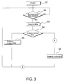
- Fig. 3
- is a flowchart showing an outline of the processing performed by
CPU 21 in an embodiment of the present invention. - Fig. 4
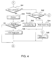
- is a flowchart showing the processing of command 11 in step S6 in the flowchart in Fig. 3.
- Fig. 5
- is a functional block diagram illustrating a second embodiment of the present invention.
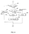
- Fig. 6
- is a flowchart showing the command processing equivalent to step S6 in the flowchart depicting the general operation of the CPU in the embodiment of Fig. 3.
- Fig. 7
- is a functional block diagram illustrating a third embodiment of the present invention.
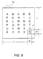
- Fig. 8
- is a diagram showing the storage of print image data in an embodiment of the present invention.
- Fig. 1 is a block diagram illustrating the functions of a printing apparatus (simply referred to as "printer" in the following) of a first embodiment of the present invention.
Host device 1 is a universal information processing device that performs various types of information processing, and it causes the desired print processing to be performed corresponding to the results of information processing by sendingdata 2, which include print data and control data, todata receiving means 4 ofprinter 3 via an interface signal line.Printer 3 comprises data receiving means 4, print image data generation means 5, first erasure means 6, storage means 7 and printing means 8. Control data are data for controlling the printer and include control commands (including print position commands) and their parameters. Below these are referred to simply as commands. Print data as the term is used in this specification include character codes, graphics language data and print format control codes (such as line feed, carriage return etc.). -
Data receiving means 4 receivesdata 2 sent fromhost device 1, distinguishes between commands 11 and printdata 12 and also analyzes commands 11.Print data 12 are sent to print image data generation means 5 and commands 11 are sent to one of the processing means (5, 6, 8) depending on the type of command. - Print image data generation means 5 generates
print image data 13 based on theprint data 12 and stores them in storage means 7. More specifically, character codes provided as print data are sent to the character generator not shown in the drawings, and character pixel patterns which are output from the character generator are sent to storage means 7 together with position information generated according to a print position command. - Storage means 7 stores
print image data 13 at positions specified by the above position information. Printimage data 13 are read out in accordance with the readrequest 15 from printing means 8. Storedprint image data 13 are erased in accordance witherasure request 16 from first erasure means 6. As described above, erasure here does not include so-called overwriting and print image data are not stored at the same time as erasure. - Printing means 8 sends read
request 15 to storage means 7 in response toprint command 11a, and printimage data 13 read out fromstorage means 7 are printed on a recording medium (not shown) at a position corresponding to their position in storage means 7. In one implementation printing means 8 includes a serial or a line print unit (not shown) comprising a print head and a mechanism for causing a relative movement between the print head and the recording medium in order to print at the prescribed position on the recording medium. Such serial print unit is well-known and its explanation is omitted here. It will be understood by those skilled in the art that the invention may be implemented with other types of print unit such as a page print unit etc.. - First erasure means 6 receives read
request 15 and detects thatprint image data 13 in storage means 7 have been read out for printing. In response to this,erasure request 16 is or is not output to storage means 7 in accordance with erasuremode selection command 11c fromdata receiving means 4. That is, if erasure has been disabled by erasuremode selection command 11c,erasure request 16 is not output, but if erasure is enabled by this command, thenerasure request 16 is output.Erasure request 16 can be output after all ofprint image data 13 are read out fromstorage means 7, or when some of the print image data are read, it can be output with designating the position of data to be erased. - Referring to Fig. 2, a circuit configuration suitable for implementing a printer according to the present invention is explained. The control circuit of
printer 3 comprisesinterface 20 for communicating withhost device 1, CPU 21 (central processing unit) which controls the electric power and electric/electronic elements ofprint unit 25 and detects their state via I/O port 24,ROM 22 which stores the program that determines the operating sequences of the CPU, andRAM 23 which makes up part of storage means 7. - In this embodiment, almost all of the functional blocks in Fig. 1 above are realized by using
CPU 21. That is, data receiving means 4 comprisesinterface 20 andCPU 21; print image data generation means comprisesROM 22, which contains a character generator, andCPU 21; storage means 7 comprisesRAM 23, which includes the so-called image buffer, andCPU 21; the first erasure means comprisesCPU 21; and the printing means 8 comprisesCPU 21, I/O port 24 andprint unit 25. - The operation of
CPU 21 corresponding to the individual functional blocks is explained below with reference to Figs. 3 and 4. Fig. 3 is a general flowchart illustrating the processing performed byCPU 21. In step S1, the power source of the printer is turned on and the entire printer is initialized. That is, following initialization ofCPU 21, the control circuit is checked for proper operation; e.g.,print unit 25 is initialized by moving the print head to a home position, etc.,RAM 23 is initialized, and the host device is notified of the printer's ready state. This processing is also performed at the time of reset resulting from operating a reset switch not shown. - Next, in step S2, a receive buffer is checked to determine if there are
data 2. The receive buffer is built intointerface 20 for temporarily storing data received according to a predetermined communication procedure withhost device 1. The well-known RS-232C interface is one example of an interface that may be employed in the present invention. If there are nodata 2 in the receive buffer, then processing loops to step S2, and if there are, then these data are acquired in step S3.Acquired data 2 are analyzed in step S4 and identified as eitherprint data 12 or a command 11. As described below, a command 11 is further analyzed in step S6 (steps S41, 42). The processing up to this point corresponds to the function of data receiving means 4 in Fig. 1. - If the data is judged to be
print data 12 in data analysis in step S4, then printimage data 13 are generated in step S5 and stored inimage buffer 7a explained in more detail below. This processing corresponds to part of the function of print image data generation means 5 and storage means 7 in Fig. 1. - An example of this processing is explained next using Fig. 8. Fig. 8 is a diagram showing an example of the storage state of print image data. In the figure, 7a is the image buffer which is a portion in
RAM 23. As an example, Fig. 8 shows the result of developingprint data 12 to print image data 13 (pixel patterns) inimage buffer 7a when the following sequence of print data and format control codes is sent from host device 1: "A, B, C, D, E, LF, F, G, H, I, J, LF, K, L, M, N, O, LF, P, Q, R, S, T, LF, U, V, W, X, Y, LF, Z, 0, 0, 0, 3". Here, "LF" is a format control code indicating line feed and is represented in hexadecimal notation as 0AH. In this embodiment, a total of 35 bytes of data (30 bytes of character codes and 5 bytes of format control codes) are sent from the host computer. - Fig. 4 is a flowchart describing the processing of commands 11 in step S6. In step S41, it is judged whether or not command 11 is
print command 11a. If it is notprint command 11a, then it is judged whether or not it is erasuremode selection command 11c in step S42. If it is not erasuremode selection command 11c, then further analysis of the command and its processing, e.g., loading of recording medium in the printer, are performed in step S45. - If it is judged to be the erasure mode selection command in step S42, then the erasure mode is set according to the selection. In this embodiment, if the command instructs erasure disable mode, then an erasure disable flag is set, while if erasure mode is instructed, this flag is reset. This erasure disable flag is referenced in step S47 upon completion of printing in step S46 described below.
- If the command 11 is judged to be a print command in step S41, then printing is performed in step S46. This printing corresponds to part of the function of printing means 8 in Fig. 1. Since, as mentioned before, printing may be performed by any of well-known print units, a detailed explanation is omitted here.
- When printing step S46 is completed, the state of the erasure disable flag mentioned above is examined. If the erasure disable flag is in a reset state,
image buffer 7a is cleared. Step S42 to step S44 and step S47 represent the function of first erasure means 6 in Fig. 1. Step S48 is included in the function of storage means 7. - Since a configuration is used wherein the erasure mode or erasure disable mode is selected in this way, data that have been sent once and developed into print image data can be repeatedly printed a plurality of times without being erased by sending a print command after selecting the erasure disable mode. Further, when updating the data to new print data, the image buffer can be cleared in advance by sending a print command for the previous data after selecting the erasure enable mode. Therefore, by sending only print data of those areas that need to be printed, printing of only those new data and without remaining previous print image data is possible.
- As will be understood, the first embodiment of the invention uses an erasure
mode selection command 11c having a parameter for selecting either erasure mode or erasure disable mode. The erasure disable flag is reset or set, respectively, in accordance with the parameter of the command. One possible modification of the first embodiment is to automatically clear the erasure disable flag at the end of the process in Fig. 4 (immediately before (B)) and to use an erasure disable command (without parameter) instead of the erasure mode selection command. Such erasure disable command sent before a print command would set the erasure disable flag and prevent theimage buffer 7a from being cleared after execution of the subsequent print command. All print commands would have to be preceded by such erasure disable command, except for the last one of a series of print commands for repeated printing of the same data and a print command for data that are to be printed one time only. - Next, a second embodiment of present invention is explained using Figs. 5 and 6. Fig. 5 is a functional block diagram of the second embodiment. In this embodiment, two types of
print command mode selection command 11c of the first embodiment is not used in the second embodiment. - Printing means 8 performs the same print processing for both of these two types of print command. That is, read
request 15 for the print image data in storage means 7 is issued, andprint image data 13 read out from storage means 7 are printed in the same way as in the first embodiment. - The difference between this embodiment and the first embodiment is in the operation of the first erasure means. That is, the first erasure means sets the erasure mode in response to
print command 11a (corresponds to command code "FF" described below) and sets the erasure disable mode in response toprint command 11d (command code "ESC FF" described below). A detailed explanation is given below with reference to Fig. 6. - Fig. 6 is a flowchart describing the command processing corresponding to step S6 in the flowchart of Fig. 3 illustrating the operation of the CPU in this embodiment of present invention. In step S61, it is judged whether or not the command is a print command. If it is not a print command, then processing corresponding to the various commands is performed in step S62. For example, the image buffer area designation command (ESC W) or the image buffer clear command (CAN) described below is executed here.
- If the command is judged to be a print command in step S61, then it is examined in step S63 which of two types of print command it is. If it is
print command 11d, i.e., command code "ESC FF" (hexadecimal 1BH 0CH), then printing is performed in step S64, but the image buffer is not cleared upon completion of printing. That is, the erasure disable mode is set. If the command is judged in step S63 to beprint command 11a, i.e., command code "FF" (hexadecimal 0CH), however, then the image buffer is cleared in step S66 upon completion of printing in step S65. - Therefore, since
image buffer 7a is cleared after printing the data of one page, for example, by using command code "FF," when the user wants to print different characters each page, the desired printing result can be obtained with the transmission and development of a small amount of print data as described above. - When control code "ESC FF" is used, however, the data of one page are printed in the same way as with the control code "FF", but
image buffer 7a is not cleared after printing. That is, this command is used when a plurality of copies of the same print image data is required, and by sending the control code "ESC FF" the same number of times as the number of copies required, it is not necessary forhost device 1 to resend the print data and forprinter 3 to generate the print image data since the print image data once developed remain in the image buffer. - Next is an explanation of a third embodiment of the present invention referring to Figs. 7 and 8. Fig. 7 is a functional block diagram of the third embodiment. Area designation means 9 and second erasure means 10 are added to the functional block diagram of the first embodiment.
- Area designation means 9 designates an area in
image buffer 7a of storage means 7 in accordance with acommand 11e identified bydata receiving means 4, and the designatedarea 18 is output to second erasure means 10. Second erasure means 10outputs erasure request 17 for the area inimage buffer 7a corresponding to designatedarea 18 to storage means 7 in accordance withcommand 11f identified bydata receiving means 4.Erasure request 17 differs fromerasure request 16 in that it is output irrespective of completion of the printing. By this means, part of the image buffer can be erased and rewritten prior to printing. The rewriting operation is explained in detail below using Fig. 8. - In this example, the print data "3" in the last line is to be incremented to "4" and "5" in subsequent printing. In the prior art, each time one page is printed, the memory is initialized and the host computer must send the following character codes and format control codes again "A, B, C, D, E, LF, F, G, H, I, J, LF, K, L, M, N, O, LF, P, Q, R, S, T, LF, U, V, W, X, Y, LF, Z, 0, 0, 0, 4, FF." It takes much time for the host device to send these data and it takes substantial time to develop the print data, which is not efficient.
- According to this third embodiment, after printing the following the host computer sends the
control command 11e "ESC W x y dx dy" after which the area of the hatched part is cleared in response to another control command "CAN" also sent from the host device.
- Here, "ESC W" is a control command that sets a rectangular area, and when expressed in hexadecimal notation, "ESC" becomes 1BH and "W" becomes 57H. "x y dx dy" are parameters for the "ESC W" command, where "x y" are the coordinates of one point of the area in the horizontal direction and the vertical direction, and "dx dy" indicate the width/height of the area in the horizontal direction and the vertical direction. Processing of this command corresponds to the function of area designation means 9 in Fig. 7.
- "CAN" is a command that clears the designated area and is 18H in hexadecimal notation. Processing of this command is equivalent to the function of second erasure means 10 in Fig. 7.
- Further, if the host computer sends the print data "4" and information on the position where it should be printed after clearing the area corresponding to that position, repeated printing of only partially changed print image data can thus be performed by merely developing one character prior to each repetition. By repeating this operation, the smallest necessary amount of data can be sent and print data developed while the character data "3" on the last line is incremented to "4" and "5", etc. thus making it possible to offer a high-throughput printer.
- While the third embodiment has been described on the basis of the first embodiment, it will be appreciated that the area designation means and the second erasure means of Fig. 7 could also be combined with the second embodiment.
- As has been described, the first and second embodiments do not have the area designation means and the second erasure means of the third embodiment. Under certain circumstances these first and second embodiments, nevertheless, allow repeated printing of only partially changed print data without requiring the whole image buffer to be rewritten. This will be explained with reference to Fig. 8. In Fig. 8, the white area within the larger square represents white or "0" pixels and the black lines forming the characters and numbers represent black or "1" pixels in the image buffer. When the image buffer has been cleared (the image data erased) all pixels are "0" pixels. Therefore, when image data are subsequently written into the image buffer it is sufficient to write only "1" pixels at the respective positions while "0" pixels need not be written. As will be understood, if only "1" pixels are written into the image buffer without clearing it before, old and new print image data may be superposed. On the other hand, if the pixel pattern employed to overwrite a certain part of the image buffer (such as the hatched area in Fig. 8) includes both "1" pixels and "0" pixels, the previous pattern in that part will be removed and replaced by the new pattern. Thus, if the character generator is capable of providing pixel patterns including "0" pixels and "1" pixels, all the host device would have to sent to the printing apparatus is the position information and the new character code thereby to allow changing some of the print image data in the image buffer and subsequently reprinting the image composed of the unchanged and the changed print image data.
- While the invention has been explained with reference to the development of character codes or graphic language data into print image data, it is to be noted that the invention is also applicable to cases where print image data are generated in the host device, sent to the printing apparatus and stored in the image buffer without requiring any development in the printing apparatus. Irrespective of whether character codes or print image data are transferred from the host device to the printing apparatus, the present invention allows to reduce the amount of data to be transferred in all cases where the same or only partially different print image data are to be printed more than one time.
Claims (6)
- A printing apparatus adapted to receive print data and control data from a host device (1), comprising:storage means (7, 7a, 23) for storing print image data corresponding to print data received from the host device,printing means (8, 21, 25) for printing said print image data on a recording medium in accordance with predetermined first control data received from the host device, andfirst erasure means (6, 21) for erasing the print image data in said storage means in response to said printing means having printed these data,characterized byerasure control means (21) responsive to predetermined second control data (11c; 11a, 11d) received from the host device (1) for enabling or disabling said first erasure means (6, 21).
- The apparatus according to Claim 1, characterized in that
said first and second control data comprise a first and a second print command (11a, 11d),
said printing means (8, 21, 25) is adapted to perform said printing in accordance with each of said print commands, and
said erasure control means (21) is responsive to one (11a) of said first and second print commands for enabling said first erasure means and responsive to the other (11d) of said first and second print commands for disabling it. - The apparatus according to Claim 1 or 2, further characterized by:
area designation means (9) responsive to predetermined third control data (11e) received from said host device (1) for designating part or all of said storage means (7), and
second erasure means (10) responsive to predetermined fourth control data (11f) received from said host device (1) for erasing only the print image data stored in the part or all of said storage means designated by said area designation means (9). - A method of controlling a printing apparatus adapted to receive print data and control data from a host device (1), comprising the steps of:(a) storing print image data corresponding to print data received from the host device in storage means (7, 7a, 23),(b) printing said print image data on a recording medium in accordance with first predetermined control data received from the host device, and(c) erasing the print image data in said storage means after they have been printed in step (b),characterized in that
step (c) is skipped in response to second predetermined control data (11c; 11a, 11d) received from the host device (1). - The method according to Claim 4, characterized in that
step (b) is performed in response to each of said first and second control data (11a, 11d). - The method according to Claim 4 or 5, characterized by comprising the further steps of:(d) designating in response to predetermined third control data (11e) received from said host device (1) a part or all of said storage means (7), and(e) erasing, in response to predetermined fourth control data (11f) received from said host device (1), only the print image data stored in the part or all of said storage means designated in step (d).
Applications Claiming Priority (3)
| Application Number | Priority Date | Filing Date | Title |
|---|---|---|---|
| JP26587895 | 1995-10-13 | ||
| JP265878/95 | 1995-10-13 | ||
| JP26587895 | 1995-10-13 |
Publications (3)
| Publication Number | Publication Date |
|---|---|
| EP0769755A2 true EP0769755A2 (en) | 1997-04-23 |
| EP0769755A3 EP0769755A3 (en) | 1998-04-22 |
| EP0769755B1 EP0769755B1 (en) | 2003-04-09 |
Family
ID=17423358
Family Applications (1)
| Application Number | Title | Priority Date | Filing Date |
|---|---|---|---|
| EP96116194A Expired - Lifetime EP0769755B1 (en) | 1995-10-13 | 1996-10-09 | Apparatus and method for printing partially repetitive data |
Country Status (4)
| Country | Link |
|---|---|
| US (2) | US6031976A (en) |
| EP (1) | EP0769755B1 (en) |
| DE (1) | DE69627266T2 (en) |
| HK (1) | HK1014282A1 (en) |
Cited By (2)
| Publication number | Priority date | Publication date | Assignee | Title |
|---|---|---|---|---|
| EP1134649A3 (en) * | 2000-03-17 | 2002-10-23 | Seiko Epson Corporation | Communication terminal device, method of processing data received by same, and computer program product for achieving the method |
| EP1594018A1 (en) * | 2003-01-28 | 2005-11-09 | Sharp Kabushiki Kaisha | Image processing method, image processing system, and image forming apparatus |
Families Citing this family (12)
| Publication number | Priority date | Publication date | Assignee | Title |
|---|---|---|---|---|
| DE69627266T2 (en) * | 1995-10-13 | 2003-12-24 | Seiko Epson Corp | Device and method for printing partially repetitive data |
| US6311237B1 (en) * | 1998-01-05 | 2001-10-30 | Canon Kabushiki Kaisha | System including single host buffer for transmit and receive data and reception buffer in interface device having stand-by area for use by host buffer when abnormal state is detected |
| JP4418545B2 (en) * | 1998-11-30 | 2010-02-17 | キヤノン株式会社 | Image processing apparatus and image output control method |
| JP4560917B2 (en) | 1999-10-15 | 2010-10-13 | セイコーエプソン株式会社 | Printer and control method thereof |
| US20020016964A1 (en) * | 2000-03-30 | 2002-02-07 | Shuntaro Aratani | Information processing apparatus and method, data broadcasting receiving apparatus, and printer |
| JP4189506B2 (en) * | 2000-06-09 | 2008-12-03 | コニカミノルタビジネステクノロジーズ株式会社 | Apparatus, method and recording medium for image processing |
| JP3520500B2 (en) * | 2000-07-26 | 2004-04-19 | セイコーエプソン株式会社 | Printer, printer control method, program therefor, and recording medium recording the program |
| US7450255B2 (en) * | 2001-01-16 | 2008-11-11 | Canon U.S.A., Inc. | Photograph record authoring system |
| JP4387687B2 (en) * | 2002-04-26 | 2009-12-16 | キヤノン株式会社 | Image processing apparatus, control method, and program |
| JP3924227B2 (en) * | 2002-09-26 | 2007-06-06 | シャープ株式会社 | Image processing device |
| JP2005130039A (en) * | 2003-10-21 | 2005-05-19 | Sharp Corp | Data processor |
| JP5404097B2 (en) * | 2009-02-27 | 2014-01-29 | キヤノン株式会社 | Image processing apparatus, control method thereof, and program |
Citations (6)
| Publication number | Priority date | Publication date | Assignee | Title |
|---|---|---|---|---|
| EP0217447A1 (en) * | 1985-09-27 | 1987-04-08 | Océ-Nederland B.V. | Raster image memory |
| WO1988001768A1 (en) * | 1986-08-25 | 1988-03-10 | Digital Equipment Corporation | Print engine drive interface |
| EP0310712A1 (en) * | 1987-10-05 | 1989-04-12 | Océ-Nederland B.V. | Front-end system for a raster output scanner |
| US5104245A (en) * | 1989-01-13 | 1992-04-14 | Casio Computer Co., Ltd. | Printing apparatus with form editor |
| WO1993001565A1 (en) * | 1991-07-08 | 1993-01-21 | Seiko Epson Corporation | Single chip page printer controller |
| JPH06282388A (en) * | 1993-03-26 | 1994-10-07 | Canon Inc | Method and device for print |
Family Cites Families (7)
| Publication number | Priority date | Publication date | Assignee | Title |
|---|---|---|---|---|
| JPS5552183A (en) * | 1978-10-11 | 1980-04-16 | Casio Comput Co Ltd | Print control unit |
| JPS60126730A (en) * | 1983-12-14 | 1985-07-06 | Brother Ind Ltd | Electronic typewriter |
| JPS6158770A (en) * | 1984-08-31 | 1986-03-26 | Pentel Kk | Printing device |
| JPS63188076A (en) * | 1987-01-31 | 1988-08-03 | Toshiba Corp | Printer |
| JPS63297082A (en) * | 1987-05-29 | 1988-12-05 | Brother Ind Ltd | Electronic typewriter |
| JPH041068A (en) * | 1990-04-18 | 1992-01-06 | Mitsubishi Electric Corp | Printer device |
| DE69627266T2 (en) * | 1995-10-13 | 2003-12-24 | Seiko Epson Corp | Device and method for printing partially repetitive data |
-
1996
- 1996-10-09 DE DE69627266T patent/DE69627266T2/en not_active Expired - Lifetime
- 1996-10-09 EP EP96116194A patent/EP0769755B1/en not_active Expired - Lifetime
- 1996-10-10 US US08/729,267 patent/US6031976A/en not_active Expired - Lifetime
-
1998
- 1998-12-24 HK HK98115560A patent/HK1014282A1/en not_active IP Right Cessation
-
1999
- 1999-11-23 US US09/448,095 patent/US6285459B1/en not_active Expired - Lifetime
Patent Citations (6)
| Publication number | Priority date | Publication date | Assignee | Title |
|---|---|---|---|---|
| EP0217447A1 (en) * | 1985-09-27 | 1987-04-08 | Océ-Nederland B.V. | Raster image memory |
| WO1988001768A1 (en) * | 1986-08-25 | 1988-03-10 | Digital Equipment Corporation | Print engine drive interface |
| EP0310712A1 (en) * | 1987-10-05 | 1989-04-12 | Océ-Nederland B.V. | Front-end system for a raster output scanner |
| US5104245A (en) * | 1989-01-13 | 1992-04-14 | Casio Computer Co., Ltd. | Printing apparatus with form editor |
| WO1993001565A1 (en) * | 1991-07-08 | 1993-01-21 | Seiko Epson Corporation | Single chip page printer controller |
| JPH06282388A (en) * | 1993-03-26 | 1994-10-07 | Canon Inc | Method and device for print |
Non-Patent Citations (1)
| Title |
|---|
| PATENT ABSTRACTS OF JAPAN vol. 095, no. 001, 28 February 1995 & JP 06 282388 A (CANON INC), 7 October 1994, * |
Cited By (5)
| Publication number | Priority date | Publication date | Assignee | Title |
|---|---|---|---|---|
| EP1134649A3 (en) * | 2000-03-17 | 2002-10-23 | Seiko Epson Corporation | Communication terminal device, method of processing data received by same, and computer program product for achieving the method |
| US6629790B2 (en) | 2000-03-17 | 2003-10-07 | Seiko Epson Corporation | Terminal printing apparatus, method of processing received data therein, and computer program product for achieving the method |
| KR100550713B1 (en) * | 2000-03-17 | 2006-02-08 | 세이코 엡슨 가부시키가이샤 | Terminal printing apparatus, method of processing received data therein, and computer program product for achieving the method |
| EP1594018A1 (en) * | 2003-01-28 | 2005-11-09 | Sharp Kabushiki Kaisha | Image processing method, image processing system, and image forming apparatus |
| EP1594018A4 (en) * | 2003-01-28 | 2010-04-07 | Sharp Kk | Image processing method, image processing system, and image forming apparatus |
Also Published As
| Publication number | Publication date |
|---|---|
| HK1014282A1 (en) | 1999-09-24 |
| DE69627266T2 (en) | 2003-12-24 |
| US6031976A (en) | 2000-02-29 |
| EP0769755B1 (en) | 2003-04-09 |
| DE69627266D1 (en) | 2003-05-15 |
| US6285459B1 (en) | 2001-09-04 |
| EP0769755A3 (en) | 1998-04-22 |
Similar Documents
| Publication | Publication Date | Title |
|---|---|---|
| EP0769755B1 (en) | Apparatus and method for printing partially repetitive data | |
| US5104245A (en) | Printing apparatus with form editor | |
| US5835122A (en) | Printing apparatus and method capable of selectively printing with a plurality of resolutions | |
| EP0387005A2 (en) | Output apparatus | |
| US6310693B1 (en) | Printing control apparatus and method, and printing system for reducing processing overhead | |
| US5740462A (en) | Output apparatus permitting font selection based on resolutions | |
| JP3871011B2 (en) | Information processing apparatus and information processing method | |
| JP3760525B2 (en) | Printing apparatus and control method thereof | |
| JP3218088B2 (en) | Printer | |
| JP2626691B2 (en) | Printing method of dot printer | |
| JP3226583B2 (en) | Color image processing system and image processing apparatus | |
| JP2711860B2 (en) | Output control method and device | |
| JP2003237147A (en) | Image processing method and image processor | |
| KR100212981B1 (en) | Image printing apparatus and method for saving paper and toner | |
| JP2989778B2 (en) | Print control apparatus and method | |
| JP3453398B2 (en) | Image processing system and image processing method | |
| JP2737883B2 (en) | Output control device | |
| JP3145460B2 (en) | Print data transfer control method | |
| JP3591096B2 (en) | How to control a page printer | |
| JPS63242561A (en) | Font reducing system | |
| JPH1198360A (en) | Device and method for processing picture and computer readable storage medium | |
| JPH05112054A (en) | Image processing device | |
| JP2715475B2 (en) | Graphic output device | |
| JPH05205015A (en) | Image processor | |
| JP2949234B2 (en) | Image processing method |
Legal Events
| Date | Code | Title | Description |
|---|---|---|---|
| PUAI | Public reference made under article 153(3) epc to a published international application that has entered the european phase |
Free format text: ORIGINAL CODE: 0009012 |
|
| AK | Designated contracting states |
Kind code of ref document: A2 Designated state(s): DE FR GB IT |
|
| PUAL | Search report despatched |
Free format text: ORIGINAL CODE: 0009013 |
|
| AK | Designated contracting states |
Kind code of ref document: A3 Designated state(s): DE FR GB IT |
|
| 17P | Request for examination filed |
Effective date: 19981022 |
|
| 17Q | First examination report despatched |
Effective date: 20000911 |
|
| GRAH | Despatch of communication of intention to grant a patent |
Free format text: ORIGINAL CODE: EPIDOS IGRA |
|
| GRAH | Despatch of communication of intention to grant a patent |
Free format text: ORIGINAL CODE: EPIDOS IGRA |
|
| GRAA | (expected) grant |
Free format text: ORIGINAL CODE: 0009210 |
|
| AK | Designated contracting states |
Designated state(s): DE FR GB IT |
|
| REG | Reference to a national code |
Ref country code: GB Ref legal event code: FG4D |
|
| ET | Fr: translation filed | ||
| PLBE | No opposition filed within time limit |
Free format text: ORIGINAL CODE: 0009261 |
|
| STAA | Information on the status of an ep patent application or granted ep patent |
Free format text: STATUS: NO OPPOSITION FILED WITHIN TIME LIMIT |
|
| 26N | No opposition filed |
Effective date: 20040112 |
|
| REG | Reference to a national code |
Ref country code: FR Ref legal event code: PLFP Year of fee payment: 20 |
|
| PGFP | Annual fee paid to national office [announced via postgrant information from national office to epo] |
Ref country code: FR Payment date: 20150908 Year of fee payment: 20 |
|
| PGFP | Annual fee paid to national office [announced via postgrant information from national office to epo] |
Ref country code: DE Payment date: 20151006 Year of fee payment: 20 Ref country code: GB Payment date: 20151007 Year of fee payment: 20 Ref country code: IT Payment date: 20151026 Year of fee payment: 20 |
|
| REG | Reference to a national code |
Ref country code: DE Ref legal event code: R071 Ref document number: 69627266 Country of ref document: DE |
|
| REG | Reference to a national code |
Ref country code: GB Ref legal event code: PE20 Expiry date: 20161008 |
|
| PG25 | Lapsed in a contracting state [announced via postgrant information from national office to epo] |
Ref country code: GB Free format text: LAPSE BECAUSE OF EXPIRATION OF PROTECTION Effective date: 20161008 |