EP0760448A2 - Integrally formed linear light strip with light emitting diodes - Google Patents
Integrally formed linear light strip with light emitting diodes Download PDFInfo
- Publication number
- EP0760448A2 EP0760448A2 EP96305859A EP96305859A EP0760448A2 EP 0760448 A2 EP0760448 A2 EP 0760448A2 EP 96305859 A EP96305859 A EP 96305859A EP 96305859 A EP96305859 A EP 96305859A EP 0760448 A2 EP0760448 A2 EP 0760448A2
- Authority
- EP
- European Patent Office
- Prior art keywords
- light strip
- led
- bus
- strip
- circuitry
- Prior art date
- Legal status (The legal status is an assumption and is not a legal conclusion. Google has not performed a legal analysis and makes no representation as to the accuracy of the status listed.)
- Granted
Links
- 238000000034 method Methods 0.000 claims abstract description 19
- 230000008569 process Effects 0.000 claims abstract description 18
- 239000000463 material Substances 0.000 claims abstract description 10
- 238000004519 manufacturing process Methods 0.000 claims abstract description 7
- 230000005611 electricity Effects 0.000 claims abstract description 6
- 230000004888 barrier function Effects 0.000 claims abstract description 3
- 239000003000 extruded plastic Substances 0.000 claims abstract description 3
- 239000000758 substrate Substances 0.000 claims description 23
- 230000001681 protective effect Effects 0.000 claims description 15
- 239000004033 plastic Substances 0.000 claims description 4
- 229920003023 plastic Polymers 0.000 claims description 4
- 229920000728 polyester Polymers 0.000 claims description 4
- 239000004642 Polyimide Substances 0.000 claims description 2
- 239000011152 fibreglass Substances 0.000 claims description 2
- 229920001903 high density polyethylene Polymers 0.000 claims description 2
- 239000004700 high-density polyethylene Substances 0.000 claims description 2
- 229920000554 ionomer Polymers 0.000 claims description 2
- 229920002493 poly(chlorotrifluoroethylene) Polymers 0.000 claims description 2
- -1 polychlorotrifluoroethylene Polymers 0.000 claims description 2
- 239000005023 polychlorotrifluoroethylene (PCTFE) polymer Substances 0.000 claims description 2
- 229920001721 polyimide Polymers 0.000 claims description 2
- 229920005989 resin Polymers 0.000 claims description 2
- 239000011347 resin Substances 0.000 claims description 2
- 238000007493 shaping process Methods 0.000 claims description 2
- 239000012815 thermoplastic material Substances 0.000 abstract description 6
- 238000003475 lamination Methods 0.000 description 7
- 229920001169 thermoplastic Polymers 0.000 description 6
- 239000004416 thermosoftening plastic Substances 0.000 description 6
- 238000001816 cooling Methods 0.000 description 4
- 230000008901 benefit Effects 0.000 description 3
- 238000001125 extrusion Methods 0.000 description 3
- 230000037361 pathway Effects 0.000 description 3
- 229910052782 aluminium Inorganic materials 0.000 description 2
- XAGFODPZIPBFFR-UHFFFAOYSA-N aluminium Chemical compound [Al] XAGFODPZIPBFFR-UHFFFAOYSA-N 0.000 description 2
- 230000015572 biosynthetic process Effects 0.000 description 2
- 239000004020 conductor Substances 0.000 description 2
- 238000005520 cutting process Methods 0.000 description 2
- 230000004044 response Effects 0.000 description 2
- 229920003182 Surlyn® Polymers 0.000 description 1
- 239000005035 Surlyn® Substances 0.000 description 1
- 230000032683 aging Effects 0.000 description 1
- 239000010426 asphalt Substances 0.000 description 1
- 230000005540 biological transmission Effects 0.000 description 1
- 239000007767 bonding agent Substances 0.000 description 1
- 238000009833 condensation Methods 0.000 description 1
- 230000005494 condensation Effects 0.000 description 1
- 230000008878 coupling Effects 0.000 description 1
- 238000010168 coupling process Methods 0.000 description 1
- 238000005859 coupling reaction Methods 0.000 description 1
- 230000001419 dependent effect Effects 0.000 description 1
- 238000006073 displacement reaction Methods 0.000 description 1
- 230000009977 dual effect Effects 0.000 description 1
- 230000000694 effects Effects 0.000 description 1
- 230000001747 exhibiting effect Effects 0.000 description 1
- 239000003673 groundwater Substances 0.000 description 1
- 229910052736 halogen Inorganic materials 0.000 description 1
- 150000002367 halogens Chemical class 0.000 description 1
- 238000005286 illumination Methods 0.000 description 1
- 230000006872 improvement Effects 0.000 description 1
- 238000005304 joining Methods 0.000 description 1
- 230000007257 malfunction Effects 0.000 description 1
- 230000013011 mating Effects 0.000 description 1
- 230000007246 mechanism Effects 0.000 description 1
- 229910052751 metal Inorganic materials 0.000 description 1
- 239000002184 metal Substances 0.000 description 1
- 239000012811 non-conductive material Substances 0.000 description 1
- 230000000149 penetrating effect Effects 0.000 description 1
- 230000035515 penetration Effects 0.000 description 1
- 229920006267 polyester film Polymers 0.000 description 1
- 238000009877 rendering Methods 0.000 description 1
- 238000007789 sealing Methods 0.000 description 1
- 210000000239 visual pathway Anatomy 0.000 description 1
- 230000004400 visual pathway Effects 0.000 description 1
- XLYOFNOQVPJJNP-UHFFFAOYSA-N water Substances O XLYOFNOQVPJJNP-UHFFFAOYSA-N 0.000 description 1
Images


Classifications
-
- H—ELECTRICITY
- H01—ELECTRIC ELEMENTS
- H01S—DEVICES USING THE PROCESS OF LIGHT AMPLIFICATION BY STIMULATED EMISSION OF RADIATION [LASER] TO AMPLIFY OR GENERATE LIGHT; DEVICES USING STIMULATED EMISSION OF ELECTROMAGNETIC RADIATION IN WAVE RANGES OTHER THAN OPTICAL
- H01S5/00—Semiconductor lasers
- H01S5/30—Structure or shape of the active region; Materials used for the active region
-
- B—PERFORMING OPERATIONS; TRANSPORTING
- B64—AIRCRAFT; AVIATION; COSMONAUTICS
- B64F—GROUND OR AIRCRAFT-CARRIER-DECK INSTALLATIONS SPECIALLY ADAPTED FOR USE IN CONNECTION WITH AIRCRAFT; DESIGNING, MANUFACTURING, ASSEMBLING, CLEANING, MAINTAINING OR REPAIRING AIRCRAFT, NOT OTHERWISE PROVIDED FOR; HANDLING, TRANSPORTING, TESTING OR INSPECTING AIRCRAFT COMPONENTS, NOT OTHERWISE PROVIDED FOR
- B64F1/00—Ground or aircraft-carrier-deck installations
- B64F1/002—Taxiing aids
-
- B—PERFORMING OPERATIONS; TRANSPORTING
- B64—AIRCRAFT; AVIATION; COSMONAUTICS
- B64F—GROUND OR AIRCRAFT-CARRIER-DECK INSTALLATIONS SPECIALLY ADAPTED FOR USE IN CONNECTION WITH AIRCRAFT; DESIGNING, MANUFACTURING, ASSEMBLING, CLEANING, MAINTAINING OR REPAIRING AIRCRAFT, NOT OTHERWISE PROVIDED FOR; HANDLING, TRANSPORTING, TESTING OR INSPECTING AIRCRAFT COMPONENTS, NOT OTHERWISE PROVIDED FOR
- B64F1/00—Ground or aircraft-carrier-deck installations
- B64F1/18—Visual or acoustic landing aids
- B64F1/20—Arrangement of optical beacons
- B64F1/205—Arrangement of optical beacons arranged underground, e.g. underground runway lighting units
-
- E—FIXED CONSTRUCTIONS
- E01—CONSTRUCTION OF ROADS, RAILWAYS, OR BRIDGES
- E01F—ADDITIONAL WORK, SUCH AS EQUIPPING ROADS OR THE CONSTRUCTION OF PLATFORMS, HELICOPTER LANDING STAGES, SIGNS, SNOW FENCES, OR THE LIKE
- E01F9/00—Arrangement of road signs or traffic signals; Arrangements for enforcing caution
- E01F9/50—Road surface markings; Kerbs or road edgings, specially adapted for alerting road users
- E01F9/576—Traffic lines
- E01F9/582—Traffic lines illuminated
-
- F—MECHANICAL ENGINEERING; LIGHTING; HEATING; WEAPONS; BLASTING
- F21—LIGHTING
- F21S—NON-PORTABLE LIGHTING DEVICES; SYSTEMS THEREOF; VEHICLE LIGHTING DEVICES SPECIALLY ADAPTED FOR VEHICLE EXTERIORS
- F21S4/00—Lighting devices or systems using a string or strip of light sources
- F21S4/20—Lighting devices or systems using a string or strip of light sources with light sources held by or within elongate supports
- F21S4/28—Lighting devices or systems using a string or strip of light sources with light sources held by or within elongate supports rigid, e.g. LED bars
-
- F—MECHANICAL ENGINEERING; LIGHTING; HEATING; WEAPONS; BLASTING
- F21—LIGHTING
- F21S—NON-PORTABLE LIGHTING DEVICES; SYSTEMS THEREOF; VEHICLE LIGHTING DEVICES SPECIALLY ADAPTED FOR VEHICLE EXTERIORS
- F21S8/00—Lighting devices intended for fixed installation
- F21S8/03—Lighting devices intended for fixed installation of surface-mounted type
- F21S8/032—Lighting devices intended for fixed installation of surface-mounted type the surface being a floor or like ground surface, e.g. pavement
-
- F—MECHANICAL ENGINEERING; LIGHTING; HEATING; WEAPONS; BLASTING
- F21—LIGHTING
- F21V—FUNCTIONAL FEATURES OR DETAILS OF LIGHTING DEVICES OR SYSTEMS THEREOF; STRUCTURAL COMBINATIONS OF LIGHTING DEVICES WITH OTHER ARTICLES, NOT OTHERWISE PROVIDED FOR
- F21V31/00—Gas-tight or water-tight arrangements
- F21V31/04—Provision of filling media
-
- G—PHYSICS
- G08—SIGNALLING
- G08B—SIGNALLING OR CALLING SYSTEMS; ORDER TELEGRAPHS; ALARM SYSTEMS
- G08B7/00—Signalling systems according to more than one of groups G08B3/00 - G08B6/00; Personal calling systems according to more than one of groups G08B3/00 - G08B6/00
- G08B7/06—Signalling systems according to more than one of groups G08B3/00 - G08B6/00; Personal calling systems according to more than one of groups G08B3/00 - G08B6/00 using electric transmission, e.g. involving audible and visible signalling through the use of sound and light sources
- G08B7/062—Signalling systems according to more than one of groups G08B3/00 - G08B6/00; Personal calling systems according to more than one of groups G08B3/00 - G08B6/00 using electric transmission, e.g. involving audible and visible signalling through the use of sound and light sources indicating emergency exits
-
- B—PERFORMING OPERATIONS; TRANSPORTING
- B64—AIRCRAFT; AVIATION; COSMONAUTICS
- B64D—EQUIPMENT FOR FITTING IN OR TO AIRCRAFT; FLIGHT SUITS; PARACHUTES; ARRANGEMENTS OR MOUNTING OF POWER PLANTS OR PROPULSION TRANSMISSIONS IN AIRCRAFT
- B64D2203/00—Aircraft or airfield lights using LEDs
-
- E—FIXED CONSTRUCTIONS
- E04—BUILDING
- E04F—FINISHING WORK ON BUILDINGS, e.g. STAIRS, FLOORS
- E04F11/00—Stairways, ramps, or like structures; Balustrades; Handrails
- E04F11/02—Stairways; Layouts thereof
- E04F11/104—Treads
- E04F2011/1046—Miscellaneous features of treads not otherwise provided for
- E04F2011/1048—Miscellaneous features of treads not otherwise provided for with lighting means
-
- F—MECHANICAL ENGINEERING; LIGHTING; HEATING; WEAPONS; BLASTING
- F21—LIGHTING
- F21V—FUNCTIONAL FEATURES OR DETAILS OF LIGHTING DEVICES OR SYSTEMS THEREOF; STRUCTURAL COMBINATIONS OF LIGHTING DEVICES WITH OTHER ARTICLES, NOT OTHERWISE PROVIDED FOR
- F21V23/00—Arrangement of electric circuit elements in or on lighting devices
- F21V23/06—Arrangement of electric circuit elements in or on lighting devices the elements being coupling devices, e.g. connectors
-
- F—MECHANICAL ENGINEERING; LIGHTING; HEATING; WEAPONS; BLASTING
- F21—LIGHTING
- F21W—INDEXING SCHEME ASSOCIATED WITH SUBCLASSES F21K, F21L, F21S and F21V, RELATING TO USES OR APPLICATIONS OF LIGHTING DEVICES OR SYSTEMS
- F21W2111/00—Use or application of lighting devices or systems for signalling, marking or indicating, not provided for in codes F21W2102/00 – F21W2107/00
- F21W2111/06—Use or application of lighting devices or systems for signalling, marking or indicating, not provided for in codes F21W2102/00 – F21W2107/00 for aircraft runways or the like
-
- F—MECHANICAL ENGINEERING; LIGHTING; HEATING; WEAPONS; BLASTING
- F21—LIGHTING
- F21Y—INDEXING SCHEME ASSOCIATED WITH SUBCLASSES F21K, F21L, F21S and F21V, RELATING TO THE FORM OR THE KIND OF THE LIGHT SOURCES OR OF THE COLOUR OF THE LIGHT EMITTED
- F21Y2115/00—Light-generating elements of semiconductor light sources
- F21Y2115/10—Light-emitting diodes [LED]
-
- Y—GENERAL TAGGING OF NEW TECHNOLOGICAL DEVELOPMENTS; GENERAL TAGGING OF CROSS-SECTIONAL TECHNOLOGIES SPANNING OVER SEVERAL SECTIONS OF THE IPC; TECHNICAL SUBJECTS COVERED BY FORMER USPC CROSS-REFERENCE ART COLLECTIONS [XRACs] AND DIGESTS
- Y10—TECHNICAL SUBJECTS COVERED BY FORMER USPC
- Y10S—TECHNICAL SUBJECTS COVERED BY FORMER USPC CROSS-REFERENCE ART COLLECTIONS [XRACs] AND DIGESTS
- Y10S362/00—Illumination
- Y10S362/80—Light emitting diode
Definitions
- the present invention relates generally to light strips and, more particularly, to an integral single piece light strip containing light emitting diodes, and a process for forming such a light strip, in which the diodes and associated circuitry are protected from moisture ingress and from other potential causes of damage.
- LED light strips are commonly used to provide visual pathways or marked locations in otherwise dark, unlit areas. Such LED light strips are advantageous when compared to bulb or lamp-based markers in that the strips are relatively inexpensive to manufacture and are relatively easy to install. Further, the LEDs used in these light strips typically have a longer life than conventional lamps or bulbs.
- LED light strips consist of circuitry including a plurality of LEDs mounted on a substrate and connected to electrical conductors.
- the circuitry is encased within a tube-like, partially transparent protective sheathing and connected to a power source for selective LED illumination.
- Two exemplary types of LED strips are described generally in U.S. Patent No. 5,130,909 to Gross, issued July 14, 1992 and entitled “Emergency Lighting Strip” and U.S. Patent No. 4,597,033 to Meggs et al., issued June 24, 1986 and entitled “Flexible Elongated Lighting System.” Such strips are utilized in a variety of indoor and outdoor configurations such as emergency pathway markers, exit door indicators and ornamental lighting arrangements.
- the LED circuitry is housed within some type of protective sheathing.
- the protective sheathing must be of sufficient strength to prevent damage to the circuitry due to excessive loads, such as the weight of machinery, being directly applied to the strip. Further, because the LED circuitry is highly susceptible to damage and malfunction caused by exposure to moisture, the protective sheathing must be impervious to moisture.
- the strips have associated limitations.
- the tube-like sheathings typically used as housings for present LED light strips provide minimal protection against mechanical damage to the LED circuitry due to excessive loads placed on the sheathings.
- the aforementioned light strips provide the LED circuitry with only limited protection from moisture.
- the sheathing seals or strip ends through which the LED circuitry is inserted are typically susceptible to moisture penetration.
- protective sheathings such as those described in the above-mentioned patents are substantially hollow, thereby increasing the susceptibility of such sheathings to moisture condensation. As a result, such light strips often prove to be unreliable from a moisture protection standpoint, especially in outdoor lighting applications or other applications in which the strips are exposed to extreme weather conditions. Consequently, it would be desirable to encase the LED circuitry in a more permanent type of protective sheathing that did not have the above mentioned drawbacks associated with tube-like sheathings.
- One such type of permanent protective sheathing is commonly used for encapsulating electroluminescent (EL) lamps and is formed by sealing a multi-layer EL lamp configuration by a conventional sheet, or hard, lamination process.
- a top layer of protective film is either adhesively bonded or thermally fused to a bottom layer of protective film through the use of high temperatures and high pressure rollers, thereby sandwiching the EL lamps between the layers.
- EL strips formed through the above hard lamination process provide a layer of protection
- the multi-layer EL lamps housed within such strips are also susceptible to moisture damage. Moisture is often capable of penetrating into the interior of the two-piece strips through the fused or bonded seal joining the two-piece housing, especially when the strips are utilized in outdoor applications or after the bonded or fused seal connecting the two-piece housing weakens upon aging of the strip.
- EL lamps include multiple layers of substantially flat conductive and non-conductive material that are easily sandwiched between top and bottom laminate layers.
- LEDs in LED light strips typically have a height of.040 inch or more
- the high pressure rollers typically used to bond or fuse the two-piece housing could crush protruding LEDs during formation of an LED strip.
- the high temperatures associated with the bonding or fusing steps in a hard lamination process would subject the LEDs and associated circuitry to heat damage, thus rendering an LED strip manufactured by such a process nonfunctional.
- the present invention relates to an integral single piece extruded LED light strip having first and second bus elements spaced apart from one another by a predetermined distance and being operatively connected to a power source to conduct electricity. Further, at least one light emitting diode (LED) is connected between the bus elements and is illuminated when the bus elements conduct electricity provided from the power source.
- An extruded soft laminate plastic material completely encapsulates the first and second bus elements and the LED, and urges the first and second bus elements and the LED into operative contact. Further, the extruded plastic material provides a barrier that protects the elements from damage and makes the light strip impervious to moisture.
- the present invention also relates to a soft lamination process for manufacturing an integrally formed single piece light strip.
- the process includes the steps of continuously feeding bus elements to an extruder; continuously feeding circuitry having at least one LED operatively mounted thereon to the extruder; and extruding a thermoplastic at a temperature below that which would damage the circuitry to thereby encapsulate the bus elements and the circuitry and to operatively connect the circuitry to the bus elements.
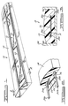
- an LED light strip according to the preferred embodiment of the present invention is shown generally at 10 in FIG. 1.
- the light strip includes LED circuitry, shown generally at 12 and described in detail below, encapsulated within an integral single piece thermoplastic housing 14 having no internal voids.
- the light strip 10 is not only durable and capable of withstanding considerable loads, but also is impervious to moisture, and thereby protects the LED circuitry 12 from damage due to moisture ingress.
- the thermoplastic housing 14 is preferably composed of a low vapor transmission rate polymeric material such as Surlyn®, an ionomer resin, a high density polyethylene, or polychlorotrifluoroethylene.
- FIG. 2 shows the light strip of FIG. 1 with the housing partially cut away along sectional line 2-2 to reveal the encapsulated LED circuitry.
- the LED circuitry 12 is mounted on a substrate 16 containing a printed circuit.
- the substrate is a polyester film having a thickness of approximately .005 inches.
- any substrate such as a fiberglass or a polyimide substrate, exhibiting parameters necessary for the manufacturing process described below may be used.
- the printed circuit includes conductive bus contacts 20a, 20b that extend longitudinally through the length of the strip and that are operatively connected to the printed circuit tracks 22.
- a resistor 24 (FIG.
- bus elements 30a, 30b are connected to a remote power source. Therefore, electricity is selectively supplied over the bus elements 30a, 30b from a remote power source to illuminate the LEDs 26 in response to certain predetermined conditions dependent upon the particular light strip application. While FIG. 1 shows three LEDs 26 mounted on the substrate 16, it should be appreciated at this point that any number of LEDs may be implemented in a similar manner.
- FIG. 3 illustrates a cross-sectional view of the light strip shown in FIG. 1.
- the light strip is approximately .4 inches in height and 1.3 inches in width.
- the LED light strip may be mounted in a protective track 34 formed from aluminum or a high density plastic. The strip is pulled into the aluminum track from one end and then is permanently attached to the track through the use of a bonding agent of the type well known in the art.
- the track 34 may be inserted into the channel and thus flush mounted with the finished surface with negligible effect on surface integrity.
- the track 34 provides additional protection to the light strip from large loads placed upon the light strip and further facilitates the flush mounting of the light strip in areas such as an airport taxiway or an automobile highway.
- a light strip/track system could include light strips using different color lamps that could alternately be activated or flashed as required by a central control such as an airport control tower. It is also contemplated that such a system could be designed to conform to the pertinent sections of FAA Circular AC150/5345-46A.
- FIG. 4 illustrates a dual extrusion assembly line for manufacturing an LED light strip according to a preferred embodiment of the present invention.
- a continuous length of an LED light strip substrate 40 including resistors and LEDs operatively mounted to a printed circuit on the substrate is fed from an LED light strip roll 42.
- a continuous length of LED light strip substrate is shown being fed from the roll 42, it should be appreciated that discrete sections of light strip substrate could also be individually fed from the roll 42 or other similar feed mechanism.
- a first continuous length of a first bus element 44 is fed from a first bus element roll 46.
- a second continuous length of a second bus element 50 is fed from a second bus element roll 52.
- the bus elements 44, 50 could also be fed in discrete sections rather than in a continuous length manner.
- the bus elements may be fed in a manner so that the elements are positioned above or below the conductive bus contacts of the substrate as desired.
- the continuous lengths of the substrate-mounted LED circuitry 40 and bus elements 44 and 50 are brought together through feeder rolls 54a and 54b, and are then fed into a molten thermoplastic stream supplied from extruders 60a and 60b in the form of both a top layer and a bottom layer.
- the thermoplastic material is extruded at a temperature less than 350° F, the temperature at which thermal distortion of the LEDs and wrinkling of the polyester substrate occurs.
- the extrusion temperature may vary according to the particular type of thermoplastic material used and the particular process parameters.
- top and bottom layers of extruded thermoplastic material are each individually profiled by forming rolls 62a, 62b upon exit of the die 56 at a temperature of approximately 340° F. It should be noted that the distance traveled from the die to the forming rolls 62a, 62b may be varied to allow for various degrees of cooling of the newly formed strip in relation to the particular mass of the extruded strip.
- both the top layer and the bottom layer of extruded material may breathe, allowing for control of extruded material displacement upon introduction of the substrate mounted LED circuitry into the extrusion, and therefore allowing excess extruded material to be vented to the side and trimmed by a strip trimmer (not shown).
- the newly formed LED light strip 63 Upon exiting the die and passing through the forming rolls 62a, 62b, the newly formed LED light strip 63 is fed into a cooling tank 64.
- the cooling tank contains cooled water into which the newly formed strip 63 is immersed for a predetermined amount of time.
- the LED light strip 63 is fed from the cooling tank 64 through feed rollers 70a, 70b to a cutting machine 72 of the type well known in the art and is cut into discrete segments of a predetermined length.
- the light strip may be cut into discrete segments corresponding to the discrete printed circuits printed on the polyester substrate to which the LEDs are electrically contacted.
- the extruded thermoplastic material thus encapsulates the substrate mounted LED circuitry and the bus elements in a single piece housing.
- each of the individual LEDs in the strip array are sealed in the thermoplastic material formed in the housing, the LEDs are isolated from one another. Thus, as the LED light strip is cut to a desired length between any discrete printed circuit formed on the polyester substrate, the LED configurations will not be exposed.
- FIG. 5 shows an alternate embodiment of the present invention generally at 110.
- a substrate 112 includes conductive bus contacts 114, 116, 120 which electrically contact bus elements 124, 126, 128.
- the bus elements 124 and 126 and the corresponding conductive bus contact strips 114 and 116 are positioned adjacent to one another, with contact strip 120 and the corresponding bus element 128 being located on the far right side of the strip 110.
- the printed circuit track 130 is thus connected between the bus contact 114 and the bus contact 120, while the printed circuit track 140 is connected between the bus contact 116 and the bus contact 120.
- a resistor 132 and LEDs 134a-134c are electrically contacted to the printed circuit track 130, while a resistor 142 and LEDs 144a-144c are electrically contacted to the printed circuit 140.
- a nonconductive pad 150 is located between the bus element 126 and the printed circuit track 130 to insulate the track 130 from electrical contact with the bus element.
- FIG. 6 shows the electrical interconnection of two LED light strips 210 and 212.
- a first end of the light strip 210 includes an electrical connector 214a, while a second end includes an electrical connector 214b.
- the light strip 212 includes a first end having an electrical connector 216a that mates with the connector 214b of the light strip 210.
- a second end of the light strip 212 includes an electrical connector 216b for connection with another light strip or with a terminating element (not shown).
- the connector 214a shown is capable of mating with an electrical socket 220 of a remote power source 222 for providing electrical power to the light strip.
- the electrical connectors 214a, 214b and 216a, 216b are metal connector pins heat staked into the thermoplastic to contact the strip bus elements for interconnection of the light strips or for connection of light strips to the power source 22. Corresponding pins in the strips may be interconnected by wires 224, 226 and then encased within a protective covering 230.
- the electrical connectors may also be of the type such as the connector disclosed in U.S. Patent No. 5,391,088, assigned to AMP, Inc. and entitled "Surface Mount Coupling Connector", hereinafter incorporated by reference.
- the housing encapsulating the bus elements could be stripped away from the bus elements and the bus elements could be interconnected or connected to a remote power source through conventional wiring techniques.
- FIG. 7 illustrates another preferred embodiment of the present invention, which is shown generally at 300.
- the light strip includes a substrate 316 including printed circuit bus contacts 320a, 320b electrically contacting bus elements 330a, 330b and PCB tracks 322 connected between the bus contacts 320a, 320b.
- a resistor 342 and LEDs 344a, 344b are mounted to the PCB tracks 322 and are selectively illuminated when the bus elements 330a, 330b conduct electricity supplied from a remote power source.
- the LED light strip 310 also includes a microcontroller 352 of the type well known in the art. The microcontroller 352 makes the strip 300 addressable so that the LED circuitry contained within the LED light strip may be pulsed or selectively illuminated in a particular pattern in order to more clearly mark a particular pathway.
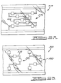
- FIG. 8 illustrates one contemplated environment in which the multiple light strips 10 of the present invention may be implemented.
- discrete sections of light strips are inserted into protective flush mounted tracks such as the track 34 and electrically interconnected by aforementioned means to form an airport holding box for a jet airplane 50. It is contemplated that implementation of these light strips for airplane holding boxes or for actual runway lighting would more clearly mark such pathways than presently used and more expensively implemented lighting systems.
- the LED light strip of the present invention represents a significant improvement over conventional airport lighting systems, such as halogen MR-16 light systems, in that LED light strips can be surface mounted to the runways with only minor disturbance to the actual integrity of the runway surface, as the light strip of the present invention eliminates the necessity of burying cables associated with typical runway light systems. Further, because the LED light strips are surface mounted, additional complications, such as problems often encountered with ground water tables, are avoided.
- the LED light strips of the present invention may be manufactured and implemented with any number of desired rows or configurations of encapsulated LEDs.
- FIGS. 9A and 9B show two such alternative configurations.
- the LED light strip shown at 400 in FIG. 9A includes a plurality of LEDs, indicated generally at 442, configured on a PCB track 422 to form an X.
- the LED light strip shown at 500 in FIG. 9B includes a plurality of LEDs, indicated generally at 542, configured on a PCB track 522 to form an arrow or chevron. Strips such as those shown at 400 and 500 could be correspondingly utilized in conjunction with a microcontroller, such as the microcontroller 352 shown in FIG. 7, to selectively indicate either a STOP or a GO condition in response to a particular runway or other type of traffic environment condition.
- a microcontroller such as the microcontroller 352 shown in FIG. 7, to selectively indicate either a STOP or a GO condition in response to a particular runway or other type of traffic environment
- bus wires may be run and any number of rows or configuration of substrate mounted LED circuits may be electrically connected to the bus elements in the process described above.
- the LED light strip of the present invention is completely impervious to moisture ingress and may therefore be used in certain underwater applications such as for aquarium or pool lighting. Use of such LED light strips could result in savings over current lighting systems.
- the LED light strips may be formed in a variety of cross-sectional shapes, such as rectangular, bowed, elliptical or any other desired shape through the above-described process through manipulation of the thermoplastic extruder on the shaping rollers in a manner well known in the art.
Abstract
Description
- The present invention relates generally to light strips and, more particularly, to an integral single piece light strip containing light emitting diodes, and a process for forming such a light strip, in which the diodes and associated circuitry are protected from moisture ingress and from other potential causes of damage.
- Light emitting diode (LED) light strips are commonly used to provide visual pathways or marked locations in otherwise dark, unlit areas. Such LED light strips are advantageous when compared to bulb or lamp-based markers in that the strips are relatively inexpensive to manufacture and are relatively easy to install. Further, the LEDs used in these light strips typically have a longer life than conventional lamps or bulbs.
- Present LED light strips consist of circuitry including a plurality of LEDs mounted on a substrate and connected to electrical conductors. The circuitry is encased within a tube-like, partially transparent protective sheathing and connected to a power source for selective LED illumination. Two exemplary types of LED strips are described generally in U.S. Patent No. 5,130,909 to Gross, issued July 14, 1992 and entitled "Emergency Lighting Strip" and U.S. Patent No. 4,597,033 to Meggs et al., issued June 24, 1986 and entitled "Flexible Elongated Lighting System." Such strips are utilized in a variety of indoor and outdoor configurations such as emergency pathway markers, exit door indicators and ornamental lighting arrangements.
- Regardless of the application, it is imperative that the LED circuitry is housed within some type of protective sheathing. The protective sheathing must be of sufficient strength to prevent damage to the circuitry due to excessive loads, such as the weight of machinery, being directly applied to the strip. Further, because the LED circuitry is highly susceptible to damage and malfunction caused by exposure to moisture, the protective sheathing must be impervious to moisture.
- While the aforementioned LED light strips protect the circuitry housed within, the strips have associated limitations. The tube-like sheathings typically used as housings for present LED light strips provide minimal protection against mechanical damage to the LED circuitry due to excessive loads placed on the sheathings. Further, the aforementioned light strips provide the LED circuitry with only limited protection from moisture. The sheathing seals or strip ends through which the LED circuitry is inserted are typically susceptible to moisture penetration. Further, protective sheathings such as those described in the above-mentioned patents are substantially hollow, thereby increasing the susceptibility of such sheathings to moisture condensation. As a result, such light strips often prove to be unreliable from a moisture protection standpoint, especially in outdoor lighting applications or other applications in which the strips are exposed to extreme weather conditions. Consequently, it would be desirable to encase the LED circuitry in a more permanent type of protective sheathing that did not have the above mentioned drawbacks associated with tube-like sheathings.
- One such type of permanent protective sheathing is commonly used for encapsulating electroluminescent (EL) lamps and is formed by sealing a multi-layer EL lamp configuration by a conventional sheet, or hard, lamination process. In this conventional hard lamination process, a top layer of protective film is either adhesively bonded or thermally fused to a bottom layer of protective film through the use of high temperatures and high pressure rollers, thereby sandwiching the EL lamps between the layers.
- While EL strips formed through the above hard lamination process provide a layer of protection, the multi-layer EL lamps housed within such strips are also susceptible to moisture damage. Moisture is often capable of penetrating into the interior of the two-piece strips through the fused or bonded seal joining the two-piece housing, especially when the strips are utilized in outdoor applications or after the bonded or fused seal connecting the two-piece housing weakens upon aging of the strip. In addition, such a hard lamination process would not be desirable for use with LED circuitry. EL lamps include multiple layers of substantially flat conductive and non-conductive material that are easily sandwiched between top and bottom laminate layers. Conversely, because LEDs in LED light strips typically have a height of.040 inch or more, the high pressure rollers typically used to bond or fuse the two-piece housing could crush protruding LEDs during formation of an LED strip. In addition, the high temperatures associated with the bonding or fusing steps in a hard lamination process would subject the LEDs and associated circuitry to heat damage, thus rendering an LED strip manufactured by such a process nonfunctional.
- Therefore, a need exists for an improved single piece integral LED light strip that is impervious to moisture and that provides a high degree of protection against other forms of potential damaging elements. There also exists a need for a soft lamination process for producing such an elongated single piece integral LED light strip in which a protective housing encapsulates the LED circuitry so that an integral single piece LED light strip is produced in a cost effective manner without subjecting the circuitry to damaging high pressures or high temperatures.
- Accordingly, the present invention relates to an integral single piece extruded LED light strip having first and second bus elements spaced apart from one another by a predetermined distance and being operatively connected to a power source to conduct electricity. Further, at least one light emitting diode (LED) is connected between the bus elements and is illuminated when the bus elements conduct electricity provided from the power source. An extruded soft laminate plastic material completely encapsulates the first and second bus elements and the LED, and urges the first and second bus elements and the LED into operative contact. Further, the extruded plastic material provides a barrier that protects the elements from damage and makes the light strip impervious to moisture.
- The present invention also relates to a soft lamination process for manufacturing an integrally formed single piece light strip. The process includes the steps of continuously feeding bus elements to an extruder; continuously feeding circuitry having at least one LED operatively mounted thereon to the extruder; and extruding a thermoplastic at a temperature below that which would damage the circuitry to thereby encapsulate the bus elements and the circuitry and to operatively connect the circuitry to the bus elements.
- These and other various advantages and features of the present invention will become apparent from the following description and claims, in conjunction with the appended drawings.
-
- FIG. 1 is a perspective view illustrating a light strip according to a preferred embodiment of the present invention;
- FIG. 2 is a perspective view, partially in cross-section and broken away, illustrating the LED circuitry encapsulated within the plastic material;
- FIG. 3 is a cross-sectional view of the strip shown in FIG. 1 mounted into a protective track;
- FIG. 4 is a schematic view illustrating a process for manufacturing the LED light strip according to the present invention;
- FIG. 5 illustrates a second embodiment of the present invention;
- FIG. 6 illustrates a third embodiment of the present invention;
- FIG. 7 illustrates a fourth embodiment of the present invention;
- FIG. 8 is a plan view illustrating the implementation of multiple discrete segments of an LED light strip of the type shown in FIG. 1 to illuminate a section of an airport taxiway; and
- FIGS. 9A-9B are plan views illustrating alternative configurations of LEDs implemented in the LED light strip of the present invention.
- Referring to the drawings, an LED light strip according to the preferred embodiment of the present invention is shown generally at 10 in FIG. 1. The light strip includes LED circuitry, shown generally at 12 and described in detail below, encapsulated within an integral single piece
thermoplastic housing 14 having no internal voids. Thus, thelight strip 10 is not only durable and capable of withstanding considerable loads, but also is impervious to moisture, and thereby protects the LED circuitry 12 from damage due to moisture ingress. Thethermoplastic housing 14 is preferably composed of a low vapor transmission rate polymeric material such as Surlyn®, an ionomer resin, a high density polyethylene, or polychlorotrifluoroethylene. - FIG. 2 shows the light strip of FIG. 1 with the housing partially cut away along sectional line 2-2 to reveal the encapsulated LED circuitry. As shown in FIG. 2, the LED circuitry 12 is mounted on a
substrate 16 containing a printed circuit. Preferably, the substrate is a polyester film having a thickness of approximately .005 inches. However, any substrate, such as a fiberglass or a polyimide substrate, exhibiting parameters necessary for the manufacturing process described below may be used. The printed circuit includes conductive bus contacts 20a, 20b that extend longitudinally through the length of the strip and that are operatively connected to the printedcircuit tracks 22. A resistor 24 (FIG. 1) and light emitting diodes (LEDs) 26 of the type well known in the art are operatively contacted to thePCB tracks 22 between the conductive bus contacts 20a, 20b. The printed circuit bus contacts 20a, 20b electricallycontact bus elements 30a, 30b, respectively, which also extend longitudinally through the length of the strip. As will be described in more detail below,bus elements 30a, 30b are connected to a remote power source. Therefore, electricity is selectively supplied over thebus elements 30a, 30b from a remote power source to illuminate theLEDs 26 in response to certain predetermined conditions dependent upon the particular light strip application. While FIG. 1 shows threeLEDs 26 mounted on thesubstrate 16, it should be appreciated at this point that any number of LEDs may be implemented in a similar manner. - FIG. 3 illustrates a cross-sectional view of the light strip shown in FIG. 1. According to the preferred embodiment of the present invention, the light strip is approximately .4 inches in height and 1.3 inches in width. Also, as shown in FIG. 3, if a particular application so dictates, the LED light strip may be mounted in a
protective track 34 formed from aluminum or a high density plastic. The strip is pulled into the aluminum track from one end and then is permanently attached to the track through the use of a bonding agent of the type well known in the art. Subsequent to the formation of a shallow channel in a concrete, asphalt or other similar surface through use of a cutting tool well known in the art, thetrack 34, and the light strip housed within, may be inserted into the channel and thus flush mounted with the finished surface with negligible effect on surface integrity. Thus, thetrack 34 provides additional protection to the light strip from large loads placed upon the light strip and further facilitates the flush mounting of the light strip in areas such as an airport taxiway or an automobile highway. Such a light strip/track system could include light strips using different color lamps that could alternately be activated or flashed as required by a central control such as an airport control tower. It is also contemplated that such a system could be designed to conform to the pertinent sections of FAA Circular AC150/5345-46A. - FIG. 4 illustrates a dual extrusion assembly line for manufacturing an LED light strip according to a preferred embodiment of the present invention. As shown, a continuous length of an LED
light strip substrate 40 including resistors and LEDs operatively mounted to a printed circuit on the substrate is fed from an LEDlight strip roll 42. Although a continuous length of LED light strip substrate is shown being fed from theroll 42, it should be appreciated that discrete sections of light strip substrate could also be individually fed from theroll 42 or other similar feed mechanism. A first continuous length of afirst bus element 44 is fed from a firstbus element roll 46. Similarly, a second continuous length of asecond bus element 50 is fed from a secondbus element roll 52. As with the light strip substrate, thebus elements LED circuitry 40 andbus elements - Once the extruders 60a and 60b have encapsulated the circuitry and the bus elements within the single piece housing, top and bottom layers of extruded thermoplastic material are each individually profiled by forming rolls 62a, 62b upon exit of the die 56 at a temperature of approximately 340° F. It should be noted that the distance traveled from the die to the forming rolls 62a, 62b may be varied to allow for various degrees of cooling of the newly formed strip in relation to the particular mass of the extruded strip.
- It should be further appreciated that, through this profiling, both the top layer and the bottom layer of extruded material may breathe, allowing for control of extruded material displacement upon introduction of the substrate mounted LED circuitry into the extrusion, and therefore allowing excess extruded material to be vented to the side and trimmed by a strip trimmer (not shown).
- Upon exiting the die and passing through the forming rolls 62a, 62b, the newly formed
LED light strip 63 is fed into a cooling tank 64. Preferably, the cooling tank contains cooled water into which the newly formedstrip 63 is immersed for a predetermined amount of time. After this predetermined amount of time, theLED light strip 63 is fed from the cooling tank 64 throughfeed rollers 70a, 70b to a cutting machine 72 of the type well known in the art and is cut into discrete segments of a predetermined length. The light strip may be cut into discrete segments corresponding to the discrete printed circuits printed on the polyester substrate to which the LEDs are electrically contacted. The extruded thermoplastic material thus encapsulates the substrate mounted LED circuitry and the bus elements in a single piece housing. Because each of the individual LEDs in the strip array are sealed in the thermoplastic material formed in the housing, the LEDs are isolated from one another. Thus, as the LED light strip is cut to a desired length between any discrete printed circuit formed on the polyester substrate, the LED configurations will not be exposed. - FIG. 5 shows an alternate embodiment of the present invention generally at 110. With the
light strip 110, asubstrate 112 includesconductive bus contacts bus elements bus elements contact strip 120 and the correspondingbus element 128 being located on the far right side of thestrip 110. The printedcircuit track 130 is thus connected between thebus contact 114 and thebus contact 120, while the printedcircuit track 140 is connected between thebus contact 116 and thebus contact 120. Aresistor 132 andLEDs 134a-134c are electrically contacted to the printedcircuit track 130, while aresistor 142 andLEDs 144a-144c are electrically contacted to the printedcircuit 140. To prevent the printedcircuit track 130 from electrically contacting thebus contact 116, anonconductive pad 150 is located between thebus element 126 and the printedcircuit track 130 to insulate thetrack 130 from electrical contact with the bus element. - FIG. 6 shows the electrical interconnection of two LED light strips 210 and 212. As shown, a first end of the
light strip 210 includes anelectrical connector 214a, while a second end includes an electrical connector 214b. Similarly, the light strip 212 includes a first end having an electrical connector 216a that mates with the connector 214b of thelight strip 210. A second end of the light strip 212 includes an electrical connector 216b for connection with another light strip or with a terminating element (not shown). Theconnector 214a shown is capable of mating with anelectrical socket 220 of aremote power source 222 for providing electrical power to the light strip. As shown, theelectrical connectors 214a, 214b and 216a, 216b are metal connector pins heat staked into the thermoplastic to contact the strip bus elements for interconnection of the light strips or for connection of light strips to thepower source 22. Corresponding pins in the strips may be interconnected bywires protective covering 230. The electrical connectors may also be of the type such as the connector disclosed in U.S. Patent No. 5,391,088, assigned to AMP, Inc. and entitled "Surface Mount Coupling Connector", hereinafter incorporated by reference. Alternatively, the housing encapsulating the bus elements could be stripped away from the bus elements and the bus elements could be interconnected or connected to a remote power source through conventional wiring techniques. - FIG. 7 illustrates another preferred embodiment of the present invention, which is shown generally at 300. The light strip includes a
substrate 316 including printed circuit bus contacts 320a, 320b electrically contacting bus elements 330a, 330b and PCB tracks 322 connected between the bus contacts 320a, 320b. Aresistor 342 andLEDs 344a, 344b are mounted to the PCB tracks 322 and are selectively illuminated when the bus elements 330a, 330b conduct electricity supplied from a remote power source. However, the LED light strip 310 also includes amicrocontroller 352 of the type well known in the art. Themicrocontroller 352 makes thestrip 300 addressable so that the LED circuitry contained within the LED light strip may be pulsed or selectively illuminated in a particular pattern in order to more clearly mark a particular pathway. - FIG. 8 illustrates one contemplated environment in which the multiple light strips 10 of the present invention may be implemented. In this particular environment, discrete sections of light strips are inserted into protective flush mounted tracks such as the
track 34 and electrically interconnected by aforementioned means to form an airport holding box for ajet airplane 50. It is contemplated that implementation of these light strips for airplane holding boxes or for actual runway lighting would more clearly mark such pathways than presently used and more expensively implemented lighting systems. In addition, the LED light strip of the present invention represents a significant improvement over conventional airport lighting systems, such as halogen MR-16 light systems, in that LED light strips can be surface mounted to the runways with only minor disturbance to the actual integrity of the runway surface, as the light strip of the present invention eliminates the necessity of burying cables associated with typical runway light systems. Further, because the LED light strips are surface mounted, additional complications, such as problems often encountered with ground water tables, are avoided. - It is also contemplated that the LED light strips of the present invention may be manufactured and implemented with any number of desired rows or configurations of encapsulated LEDs. FIGS. 9A and 9B show two such alternative configurations. The LED light strip shown at 400 in FIG. 9A includes a plurality of LEDs, indicated generally at 442, configured on a
PCB track 422 to form an X. The LED light strip shown at 500 in FIG. 9B includes a plurality of LEDs, indicated generally at 542, configured on aPCB track 522 to form an arrow or chevron. Strips such as those shown at 400 and 500 could be correspondingly utilized in conjunction with a microcontroller, such as themicrocontroller 352 shown in FIG. 7, to selectively indicate either a STOP or a GO condition in response to a particular runway or other type of traffic environment condition. - It should be appreciated that any number of bus wires may be run and any number of rows or configuration of substrate mounted LED circuits may be electrically connected to the bus elements in the process described above.
- Further, it should be appreciated that the LED light strip of the present invention is completely impervious to moisture ingress and may therefore be used in certain underwater applications such as for aquarium or pool lighting. Use of such LED light strips could result in savings over current lighting systems.
- It should also be appreciated that the LED light strips may be formed in a variety of cross-sectional shapes, such as rectangular, bowed, elliptical or any other desired shape through the above-described process through manipulation of the thermoplastic extruder on the shaping rollers in a manner well known in the art.
- While the above description constitutes the preferred embodiment of the present invention, it should be appreciated that the invention may be modified without departing from the proper scope or fair meaning of the accompanying claims. Various other advantages of the present invention will become apparent to those skilled in the art after having the benefit of studying the foregoing text and drawings taken in conjunction with the following claims.
Claims (10)
- An integrally formed single piece light strip having no internal voids, comprising:first and second bus elements spaced apart from one another by a predetermined distance and being operatively connected to a power source;at least one light emitting diode (LED) connected between said first and second bus elements, said LED being illuminated upon said bus elements conducting electricity; andan extruded plastic material completely encapsulating said first and second bus elements and said LED for providing a protective barrier and for making said light strip impervious to moisture.
- The light strip of Claim 1, further comprising at least one resistor connected in series with said LED between said first and second bus elements.
- The light strip of Claim 1, further comprising a first plurality of LEDs connected between said first and second bus elements.
- The light strip of Claim 3, further comprising a substrate strip having a plurality of discrete printed circuits thereon, said LEDs being mounted on said discrete printed circuits to permit said light strip to be cut into discrete segments corresponding to said discrete printed circuits.
- The light strip of Claim 4, wherein said substrate strip comprises a polyester, fiberglass or polyimide substrate strip.
- The light strip of Claim 1, further comprising a third bus element operatively connected to said power source;at least one resistor operatively connected in parallel between said third bus element and said second bus element; andat least one LED connected in series with said resistor.
- The light strip of Claim 1, wherein said extruded material comprises an ionomer resin, high density polyethylene, or polychlorotrifluoroethylene.
- The light strip of Claim 1, further comprising an elongated channeled track for housing said light strip.
- A process for manufacturing an integrally formed single piece light strip, comprising the steps of:continuously feeding bus elements to an extruder;continuously feeding circuitry having at least one LED operatively mounted thereon to said extruder; andextruding a plastic at a temperature below that which would damage said circuitry to encapsulate said bus elements, said circuitry and said LED.
- The process of Claim 9, further comprising the step of passing said encapsulated bus elements and said circuitry between shaping rollers to shape said light strip.
Applications Claiming Priority (2)
| Application Number | Priority Date | Filing Date | Title |
|---|---|---|---|
| US520237 | 1990-05-07 | ||
| US08/520,237 US5927845A (en) | 1995-08-28 | 1995-08-28 | Integrally formed linear light strip with light emitting diodes |
Publications (3)
| Publication Number | Publication Date |
|---|---|
| EP0760448A2 true EP0760448A2 (en) | 1997-03-05 |
| EP0760448A3 EP0760448A3 (en) | 1997-12-29 |
| EP0760448B1 EP0760448B1 (en) | 2004-07-07 |
Family
ID=24071743
Family Applications (1)
| Application Number | Title | Priority Date | Filing Date |
|---|---|---|---|
| EP96305859A Expired - Lifetime EP0760448B1 (en) | 1995-08-28 | 1996-08-09 | Integrally formed linear light strip with light emitting diodes |
Country Status (7)
| Country | Link |
|---|---|
| US (2) | US5927845A (en) |
| EP (1) | EP0760448B1 (en) |
| JP (1) | JPH09185911A (en) |
| KR (1) | KR100452394B1 (en) |
| AT (1) | ATE270759T1 (en) |
| CA (1) | CA2182548A1 (en) |
| DE (1) | DE69632848T2 (en) |
Cited By (30)
| Publication number | Priority date | Publication date | Assignee | Title |
|---|---|---|---|---|
| EP0818652A2 (en) * | 1996-07-11 | 1998-01-14 | HAPPICH Fahrzeug- und Industrieteile GmbH | Lighting strip an method of manufacturing |
| WO1998023896A1 (en) * | 1996-11-25 | 1998-06-04 | Leo Hatjasalo | Method for production of conducting element and conducting element |
| EP0923696A1 (en) * | 1996-09-03 | 1999-06-23 | Stantech | Integrally formed linear light strip with light emitting diodes |
| WO1999041785A1 (en) | 1998-02-12 | 1999-08-19 | Gerhard Staufert | Adaptable led light panel |
| NL1010491C2 (en) * | 1998-11-05 | 2000-05-09 | Ireneus Johannes Theodorus Mar | Light emitting, road surface traffic element includes a transparent plastic component fabricated from a multicomponent plastic in a closed mold by casting |
| EP0911573A3 (en) * | 1997-10-20 | 2001-02-14 | The Standard Products Company | Automated system and method for manufacturing an led light strip having an integrally formed connector |
| FR2807609A1 (en) * | 2000-04-11 | 2001-10-12 | Festilight | LUMINOUS ANIMATION DEVICE |
| EP1341142A2 (en) * | 2002-03-01 | 2003-09-03 | Hans-Thomas Hansen | LED illuminant |
| EP1162400A3 (en) * | 2000-06-09 | 2004-04-21 | Omnilux s.r.l. | Modular lighting elements with leds (light-emitting diodes) |
| US6777889B2 (en) | 2000-04-11 | 2004-08-17 | Festilight Sarl | Light animation device |
| EP1498656A2 (en) * | 2003-07-14 | 2005-01-19 | Elektro Pro Light KG des Bergmeister Markus & Co. | Lighting device, in particular tunnel lighting |
| FR2904682A1 (en) * | 2006-08-04 | 2008-02-08 | Thierry Marquet | Support e.g. floorboard, manufacturing method, involves introducing connection element in housing at viscous state, and hardening connection element, and sandpapering surface visible at level of orifice |
| WO2008031580A1 (en) * | 2006-09-12 | 2008-03-20 | Paul Lo | Integrally formed single piece light emitting diode light wire |
| WO2008112284A1 (en) * | 2007-03-13 | 2008-09-18 | Sloanled, Inc. | Perimeter lighting |
| WO2010081559A1 (en) * | 2009-01-16 | 2010-07-22 | United Luminous International (Holdings) Limited | Integrally formed single piece light emitting diode light wire and uses thereof |
| EP2222147A1 (en) * | 2009-02-20 | 2010-08-25 | Shenzen Clear Illuminating Technology Co., Ltd. | A light strip and a method for making the same |
| WO2011003713A1 (en) * | 2009-07-09 | 2011-01-13 | Osram Gesellschaft mit beschränkter Haftung | Luminous device having a flexible printed circuit board |
| WO2011110217A1 (en) | 2010-03-09 | 2011-09-15 | Tri-O-Light Bv | Light strip |
| WO2011117468A3 (en) * | 2010-03-23 | 2011-11-17 | Marimils Oy | Light stripe and manufacturing of light stripe |
| WO2011069844A3 (en) * | 2009-12-10 | 2011-12-08 | Osram Gesellschaft mit beschränkter Haftung | Method for contacting a lighting device, tool for performing the method and connection element for attachment on a lighting device |
| DE102010048703A1 (en) | 2010-10-19 | 2012-04-19 | W. Döllken & Co. GmbH | Method for continuously producing an LED strip |
| DE102010048705A1 (en) | 2010-10-19 | 2012-04-19 | W. Döllken & Co. GmbH | Device for the continuous production of an LED strip |
| EP2484956A1 (en) * | 2011-02-04 | 2012-08-08 | Luxall S.r.l. | LED, OLED, EL light sources encapsulated by coextrusion in a silicone elastomer crosslinkable without heat with UV rays comprising heat-conductive materials, and the preparation process thereof |
| WO2012146555A1 (en) * | 2011-04-29 | 2012-11-01 | Osram Ag | Lighting device and method for producing a lighting device |
| US8567992B2 (en) | 2006-09-12 | 2013-10-29 | Huizhou Light Engine Ltd. | Integrally formed light emitting diode light wire and uses thereof |
| EP2505906A3 (en) * | 2011-03-30 | 2014-01-22 | W. Döllken & Co. GmbH | Method for producing a lighting body on an LED basis |
| US8807796B2 (en) | 2006-09-12 | 2014-08-19 | Huizhou Light Engine Ltd. | Integrally formed light emitting diode light wire and uses thereof |
| CN104228027A (en) * | 2014-09-24 | 2014-12-24 | 无锡晶睿光电新材料有限公司 | Manufacturing method of silicone rubber-coated LED flexible lamp bar |
| DE102015005285A1 (en) * | 2015-04-25 | 2016-10-27 | Happich Gmbh | lighting bar |
| WO2020001952A1 (en) * | 2018-06-26 | 2020-01-02 | Rehau Ag + Co | Method for producing an extrusion profile having at least one electronic component |
Families Citing this family (151)
| Publication number | Priority date | Publication date | Assignee | Title |
|---|---|---|---|---|
| US5927845A (en) * | 1995-08-28 | 1999-07-27 | Stantech | Integrally formed linear light strip with light emitting diodes |
| US20040052076A1 (en) | 1997-08-26 | 2004-03-18 | Mueller George G. | Controlled lighting methods and apparatus |
| US6806659B1 (en) | 1997-08-26 | 2004-10-19 | Color Kinetics, Incorporated | Multicolored LED lighting method and apparatus |
| US6936978B2 (en) * | 1997-08-26 | 2005-08-30 | Color Kinetics Incorporated | Methods and apparatus for remotely controlled illumination of liquids |
| US6781329B2 (en) * | 1997-08-26 | 2004-08-24 | Color Kinetics Incorporated | Methods and apparatus for illumination of liquids |
| US6777891B2 (en) | 1997-08-26 | 2004-08-17 | Color Kinetics, Incorporated | Methods and apparatus for controlling devices in a networked lighting system |
| US6720745B2 (en) * | 1997-08-26 | 2004-04-13 | Color Kinetics, Incorporated | Data delivery track |
| US6717376B2 (en) | 1997-08-26 | 2004-04-06 | Color Kinetics, Incorporated | Automotive information systems |
| US6774584B2 (en) | 1997-08-26 | 2004-08-10 | Color Kinetics, Incorporated | Methods and apparatus for sensor responsive illumination of liquids |
| US20030133292A1 (en) | 1999-11-18 | 2003-07-17 | Mueller George G. | Methods and apparatus for generating and modulating white light illumination conditions |
| WO2001025681A1 (en) | 1999-10-04 | 2001-04-12 | Hutchins Nicolas D | Elongated light emitting diode lighting system |
| US6196471B1 (en) | 1999-11-30 | 2001-03-06 | Douglas Ruthenberg | Apparatus for creating a multi-colored illuminated waterfall or water fountain |
| US7049761B2 (en) | 2000-02-11 | 2006-05-23 | Altair Engineering, Inc. | Light tube and power supply circuit |
| US6259375B1 (en) | 2000-03-09 | 2001-07-10 | Roger J. Andras | Highway warning system |
| US6354714B1 (en) * | 2000-04-04 | 2002-03-12 | Michael Rhodes | Embedded led lighting system |
| PT1422975E (en) | 2000-04-24 | 2010-07-09 | Philips Solid State Lighting | Light-emitting diode based product |
| US7303300B2 (en) | 2000-09-27 | 2007-12-04 | Color Kinetics Incorporated | Methods and systems for illuminating household products |
| US7052170B2 (en) * | 2000-09-29 | 2006-05-30 | Striebel Roman F | Super bright LED utility and emergency light |
| US6676278B2 (en) | 2000-09-29 | 2004-01-13 | Suncor Stainless, Inc. | Super bright LED utility and emergency light |
| US7168843B2 (en) * | 2000-09-29 | 2007-01-30 | Suncor Stainless, Inc. | Modular lighting bar |
| US6502953B2 (en) | 2000-12-29 | 2003-01-07 | Mohammed Ali Hajianpour | Floating light for a swimming pool |
| US6801003B2 (en) | 2001-03-13 | 2004-10-05 | Color Kinetics, Incorporated | Systems and methods for synchronizing lighting effects |
| DE10133255A1 (en) * | 2001-07-09 | 2003-01-30 | Osram Opto Semiconductors Gmbh | LED module for lighting devices |
| US6871981B2 (en) | 2001-09-13 | 2005-03-29 | Heads Up Technologies, Inc. | LED lighting device and system |
| US6739735B2 (en) * | 2001-09-20 | 2004-05-25 | Illuminated Guidance Systems, Inc. | Lighting strip for direction and guidance systems |
| US6932495B2 (en) * | 2001-10-01 | 2005-08-23 | Sloanled, Inc. | Channel letter lighting using light emitting diodes |
| US20030125110A1 (en) * | 2001-12-27 | 2003-07-03 | Lalley Timothy J. | Games utilizing electronic display strips and methods of making display strips |
| TW558804B (en) * | 2002-04-16 | 2003-10-21 | Yuan Lin | Flexible light emitting device and the manufacturing method thereof |
| US6851832B2 (en) * | 2002-05-21 | 2005-02-08 | Dwayne A. Tieszen | Led tube light housings |
| GB0216787D0 (en) * | 2002-07-19 | 2002-08-28 | Pilkington Plc | Laminated glazing panel |
| US8950908B2 (en) * | 2009-12-08 | 2015-02-10 | Daniel Joseph Berman | Recessed lighting strip that interlocks between insulated roof panels |
| WO2004070262A2 (en) * | 2003-02-04 | 2004-08-19 | Ilight Technologies, Inc. | Flexible illumination device for simulating neon lighting |
| DE10319525B4 (en) * | 2003-04-30 | 2006-08-31 | Alcan Technology & Management Ltd. | Band-shaped arrangement with a conductor track structure and with it electrically connected electronic components, in particular light band with lighting elements |
| US7178941B2 (en) | 2003-05-05 | 2007-02-20 | Color Kinetics Incorporated | Lighting methods and systems |
| US6882111B2 (en) * | 2003-07-09 | 2005-04-19 | Tir Systems Ltd. | Strip lighting system incorporating light emitting devices |
| US7679096B1 (en) | 2003-08-21 | 2010-03-16 | Opto Technology, Inc. | Integrated LED heat sink |
| DK1706541T3 (en) * | 2003-11-26 | 2014-03-03 | Geveko Its As | Road marking device |
| EP1711737B1 (en) * | 2004-01-28 | 2013-09-18 | Koninklijke Philips Electronics N.V. | Sealed housing unit for lighting system |
| US7241031B2 (en) * | 2004-04-14 | 2007-07-10 | Sloanled, Inc. | Channel letter lighting system using high output white light emitting diodes |
| US7213941B2 (en) * | 2004-04-14 | 2007-05-08 | Sloanled, Inc. | Flexible perimeter lighting apparatus |
| US8188503B2 (en) | 2004-05-10 | 2012-05-29 | Permlight Products, Inc. | Cuttable illuminated panel |
| US7273300B2 (en) * | 2004-08-06 | 2007-09-25 | Lumination Llc | Curvilinear LED light source |
| US7750352B2 (en) * | 2004-08-10 | 2010-07-06 | Pinion Technologies, Inc. | Light strips for lighting and backlighting applications |
| DE502006000775D1 (en) | 2005-02-11 | 2008-07-03 | Kompled Gmbh & Co Kg | Vehicle exterior light and method for producing such a vehicle exterior light |
| DE102005025214A1 (en) * | 2005-02-11 | 2006-08-24 | Schmitz Gotha Fahrzeugwerke Gmbh | Motor vehicle e.g. heavy goods vehicle, external lighting, has electronic light sources and electrical conductors, which are encased by casting, which is made of casting compound, where the casting is free from cavities |
| DE102005006593A1 (en) * | 2005-02-11 | 2006-08-24 | Schmitz Gotha Fahrzeugwerke Gmbh | Vehicle light arrangement |
| CA2620750A1 (en) * | 2005-05-20 | 2006-11-23 | Tir Technology Lp | Cove illumination module and system |
| US20070008167A1 (en) * | 2005-07-05 | 2007-01-11 | Parker Richard Jr | Lighting system |
| US7384165B2 (en) * | 2005-07-05 | 2008-06-10 | Kevin Doyle | Water feature with an LED system |
| US7375653B2 (en) * | 2005-08-22 | 2008-05-20 | West Fork Holdings | Precision approach path indicator systems and light assemblies useful in same |
| US20070070618A1 (en) * | 2005-09-27 | 2007-03-29 | Talamo John A | Lighted guide strip |
| US7500761B2 (en) * | 2006-05-06 | 2009-03-10 | Shen-Ko Tseng | Circuit device for controlling a plurality of light-emitting devices in a sequence |
| WO2008024761A2 (en) * | 2006-08-21 | 2008-02-28 | Innotec Corporation | Electrical device having boardless electrical component mounting arrangement |
| TW200824142A (en) * | 2006-11-22 | 2008-06-01 | Lighthouse Technology Co Ltd | High power diode holder and thereof package is described |
| US7815341B2 (en) * | 2007-02-14 | 2010-10-19 | Permlight Products, Inc. | Strip illumination device |
| US8408773B2 (en) | 2007-03-19 | 2013-04-02 | Innotec Corporation | Light for vehicles |
| US7712933B2 (en) * | 2007-03-19 | 2010-05-11 | Interlum, Llc | Light for vehicles |
| US7866104B2 (en) * | 2007-05-16 | 2011-01-11 | Asb-Systembau Horst Babinsky Gmbh | Base structure for squash courts |
| US7722207B2 (en) * | 2007-06-01 | 2010-05-25 | Creative Industries, Llc | Baluster lighting assembly and method |
| DE202007010221U1 (en) * | 2007-07-23 | 2008-12-04 | Agor Gmbh & Co. Kg | light strip |
| DE102007043401A1 (en) * | 2007-09-12 | 2009-03-19 | Osram Gesellschaft mit beschränkter Haftung | Lighting device and method for producing the same |
| WO2009076579A2 (en) * | 2007-12-12 | 2009-06-18 | Innotec Corporation | Overmolded circuit board and method |
| US8118447B2 (en) | 2007-12-20 | 2012-02-21 | Altair Engineering, Inc. | LED lighting apparatus with swivel connection |
| US7712918B2 (en) | 2007-12-21 | 2010-05-11 | Altair Engineering , Inc. | Light distribution using a light emitting diode assembly |
| DE202008003420U1 (en) * | 2008-03-11 | 2009-04-23 | Pöllet, Wilfried | Strip light with several bulbs, preferably LEDs |
| US7832896B2 (en) | 2008-04-18 | 2010-11-16 | Lumination Llc | LED light engine |
| DE102008024551A1 (en) * | 2008-05-21 | 2009-11-26 | Tesa Se | Method for encapsulating optoelectronic components |
| US8360599B2 (en) | 2008-05-23 | 2013-01-29 | Ilumisys, Inc. | Electric shock resistant L.E.D. based light |
| DE102008025398B4 (en) * | 2008-05-28 | 2018-04-26 | Osram Gmbh | Protective cladding for a LED band |
| CA2667312A1 (en) * | 2008-05-29 | 2009-11-29 | Norm Tarko | Light strip |
| US7976196B2 (en) | 2008-07-09 | 2011-07-12 | Altair Engineering, Inc. | Method of forming LED-based light and resulting LED-based light |
| US20100014288A1 (en) * | 2008-07-15 | 2010-01-21 | Presence From Innovation, Llc | Retro-fit light stick device and secondary light source or other electrical device for use with walk-in type coolers and other product display units |
| US7946729B2 (en) | 2008-07-31 | 2011-05-24 | Altair Engineering, Inc. | Fluorescent tube replacement having longitudinally oriented LEDs |
| US8674626B2 (en) | 2008-09-02 | 2014-03-18 | Ilumisys, Inc. | LED lamp failure alerting system |
| US8256924B2 (en) | 2008-09-15 | 2012-09-04 | Ilumisys, Inc. | LED-based light having rapidly oscillating LEDs |
| US20100097791A1 (en) * | 2008-10-18 | 2010-04-22 | Chang Kai-Nan | Light emitting diode (led) strip light |
| US8214084B2 (en) | 2008-10-24 | 2012-07-03 | Ilumisys, Inc. | Integration of LED lighting with building controls |
| US8653984B2 (en) | 2008-10-24 | 2014-02-18 | Ilumisys, Inc. | Integration of LED lighting control with emergency notification systems |
| US8324817B2 (en) | 2008-10-24 | 2012-12-04 | Ilumisys, Inc. | Light and light sensor |
| US7938562B2 (en) | 2008-10-24 | 2011-05-10 | Altair Engineering, Inc. | Lighting including integral communication apparatus |
| US8901823B2 (en) | 2008-10-24 | 2014-12-02 | Ilumisys, Inc. | Light and light sensor |
| US8444292B2 (en) | 2008-10-24 | 2013-05-21 | Ilumisys, Inc. | End cap substitute for LED-based tube replacement light |
| US8556452B2 (en) | 2009-01-15 | 2013-10-15 | Ilumisys, Inc. | LED lens |
| US8362710B2 (en) | 2009-01-21 | 2013-01-29 | Ilumisys, Inc. | Direct AC-to-DC converter for passive component minimization and universal operation of LED arrays |
| AU2011213705B2 (en) * | 2009-01-16 | 2011-10-27 | Huizhou Light Engine Ltd. | Integrally formed single piece light emitting diode light wire and uses thereof |
| US8664880B2 (en) | 2009-01-21 | 2014-03-04 | Ilumisys, Inc. | Ballast/line detection circuit for fluorescent replacement lamps |
| US8057060B2 (en) * | 2009-04-16 | 2011-11-15 | Cogent Designs, Inc. | Aquarium light fixture with latch mechanism and bracket |
| DE202009018087U1 (en) * | 2009-04-30 | 2011-02-03 | Saint-Gobain Sekurit Deutschland Gmbh & Co. Kg | disk assembly |
| US8330381B2 (en) | 2009-05-14 | 2012-12-11 | Ilumisys, Inc. | Electronic circuit for DC conversion of fluorescent lighting ballast |
| US8299695B2 (en) | 2009-06-02 | 2012-10-30 | Ilumisys, Inc. | Screw-in LED bulb comprising a base having outwardly projecting nodes |
| EP2446715A4 (en) | 2009-06-23 | 2013-09-11 | Ilumisys Inc | Illumination device including leds and a switching power control system |
| US20110047901A1 (en) * | 2009-09-03 | 2011-03-03 | Dierbeck Robert F | Extruded Aluminum Deck Plank with Lighting and Heating Features |
| EP2480819B1 (en) * | 2009-09-25 | 2015-11-04 | OSRAM Opto Semiconductors GmbH | Luminaire |
| WO2011064861A1 (en) * | 2009-11-26 | 2011-06-03 | Cheng Chiang-Ming | Multifunction lighting device |
| DE102009056651A1 (en) * | 2009-12-02 | 2011-06-09 | Torsten Korn | Marking unit for identification marking of spatial or planar structures, has lighting unit that is attached on or in carrier material and on surface of adhesive medium |
| EP2553320A4 (en) | 2010-03-26 | 2014-06-18 | Ilumisys Inc | Led light with thermoelectric generator |
| WO2011119958A1 (en) | 2010-03-26 | 2011-09-29 | Altair Engineering, Inc. | Inside-out led bulb |
| WO2011119907A2 (en) | 2010-03-26 | 2011-09-29 | Altair Engineering, Inc. | Led light tube with dual sided light distribution |
| US8230815B2 (en) | 2010-04-14 | 2012-07-31 | Current USA | Aquarium light strip |
| US8973532B2 (en) | 2010-04-14 | 2015-03-10 | Current-Usa, Inc. | Aquarium light fixture with hinge |
| US8100087B2 (en) | 2010-04-14 | 2012-01-24 | Cogent Designs, Inc. | Aquarium light fixture with hinge |
| US8844469B2 (en) | 2010-04-14 | 2014-09-30 | Cogent Designs, Inc. | Aquarium light fixture with hinge |
| US8646934B2 (en) | 2010-04-14 | 2014-02-11 | Cogent Designs, Inc. | Aquarium light strip |
| US8454193B2 (en) | 2010-07-08 | 2013-06-04 | Ilumisys, Inc. | Independent modules for LED fluorescent light tube replacement |
| US8596813B2 (en) | 2010-07-12 | 2013-12-03 | Ilumisys, Inc. | Circuit board mount for LED light tube |
| EP2633227B1 (en) | 2010-10-29 | 2018-08-29 | iLumisys, Inc. | Mechanisms for reducing risk of shock during installation of light tube |
| US8870415B2 (en) | 2010-12-09 | 2014-10-28 | Ilumisys, Inc. | LED fluorescent tube replacement light with reduced shock hazard |
| DE202010017031U1 (en) | 2010-12-29 | 2011-03-03 | W. Döllken & Co. GmbH | Guard rail for a carriageway |
| US9174691B2 (en) | 2011-07-21 | 2015-11-03 | Dan Goldwater | Universal mount battery holder for bicycles |
| US8789988B2 (en) | 2011-07-21 | 2014-07-29 | Dan Goldwater | Flexible LED light strip for a bicycle and method for making the same |
| US9072171B2 (en) | 2011-08-24 | 2015-06-30 | Ilumisys, Inc. | Circuit board mount for LED light |
| US8752972B2 (en) | 2011-10-07 | 2014-06-17 | Patno Enterprise, Llc | Lighting system |
| US20130099666A1 (en) * | 2011-10-21 | 2013-04-25 | Almax Rp Corp. | Selectively controlling the resistance of resistive traces printed on a substrate to supply equal current to an array of light sources |
| JP5512744B2 (en) * | 2011-10-31 | 2014-06-04 | エイテックス株式会社 | Circuit board for LED mounting, strip-shaped flexible LED light, and LED lighting device using the same |
| US9184518B2 (en) | 2012-03-02 | 2015-11-10 | Ilumisys, Inc. | Electrical connector header for an LED-based light |
| WO2013188678A1 (en) | 2012-06-13 | 2013-12-19 | Innotec, Corp. | Flexible light pipe |
| WO2014008463A1 (en) | 2012-07-06 | 2014-01-09 | Ilumisys, Inc. | Power supply assembly for led-based light tube |
| US9271367B2 (en) | 2012-07-09 | 2016-02-23 | Ilumisys, Inc. | System and method for controlling operation of an LED-based light |
| US20140016298A1 (en) * | 2012-07-16 | 2014-01-16 | The Sloan Company, Inc. Dba Sloanled | Flexible ribbon led module |
| DE102012214488B4 (en) * | 2012-08-14 | 2022-07-28 | Osram Gmbh | Production of a strip-shaped light module |
| US8794795B2 (en) | 2012-08-31 | 2014-08-05 | Axis Lighting Inc. | Adjustable LED assembly, optical system using same and method of assembly therefor |
| US8704448B2 (en) * | 2012-09-06 | 2014-04-22 | Cooledge Lighting Inc. | Wiring boards for array-based electronic devices |
| US9506633B2 (en) * | 2012-09-06 | 2016-11-29 | Cooledge Lighting Inc. | Sealed and sealable lighting systems incorporating flexible light sheets and related methods |
| US9353913B2 (en) | 2013-02-13 | 2016-05-31 | Elive Llc | LED track lighting |
| US9285084B2 (en) | 2013-03-14 | 2016-03-15 | Ilumisys, Inc. | Diffusers for LED-based lights |
| US10217387B2 (en) | 2013-03-15 | 2019-02-26 | General Led Opco, Llc | LED light engine for signage |
| US9626884B2 (en) | 2013-03-15 | 2017-04-18 | General Led, Inc. | LED light engine for signage |
| US9464780B2 (en) | 2013-03-15 | 2016-10-11 | General Led, Inc. | LED light engine for signage |
| US9603346B2 (en) | 2013-04-16 | 2017-03-28 | Elive Llc | Aquarium lighting system |
| DE102013211457A1 (en) * | 2013-06-19 | 2014-12-24 | Osram Gmbh | Optoelectronic assembly and method for manufacturing an optoelectronic assembly |
| US9644833B1 (en) | 2013-10-04 | 2017-05-09 | Universal Lighting Technologies, Inc. | Encapsulated LED lighting module with integral gas venting |
| USD737713S1 (en) * | 2013-10-07 | 2015-09-01 | SpeedTech Lights Inc. | Emergency vehicle light bar |
| US9267650B2 (en) | 2013-10-09 | 2016-02-23 | Ilumisys, Inc. | Lens for an LED-based light |
| US9574717B2 (en) | 2014-01-22 | 2017-02-21 | Ilumisys, Inc. | LED-based light with addressed LEDs |
| US9618169B2 (en) * | 2014-02-10 | 2017-04-11 | Hartman Design, Inc. | Lighting element for illuminated hardscape |
| USD754373S1 (en) | 2014-03-10 | 2016-04-19 | Elive Llc | LED track lighting module |
| US9198236B1 (en) | 2014-05-07 | 2015-11-24 | Grote Industries, Llc | System and method for controlling a multiple-color lighting device |
| US9510400B2 (en) | 2014-05-13 | 2016-11-29 | Ilumisys, Inc. | User input systems for an LED-based light |
| US9671075B2 (en) | 2014-06-02 | 2017-06-06 | Jason Greene | Light strip and method for making a light strip |
| US10032753B2 (en) * | 2014-06-20 | 2018-07-24 | Grote Industries, Llc | Flexible lighting device having both visible and infrared light-emitting diodes |
| USD750824S1 (en) | 2014-06-21 | 2016-03-01 | Christopher Claude Bonang | Illuminated LED strip for use as a headband necklace or bracelet |
| AT516127B1 (en) * | 2014-07-28 | 2016-10-15 | Fame Tech Gmbh | Profile element with incorporated therein bulbs |
| HK1207250A2 (en) * | 2014-10-15 | 2016-01-22 | 新照明設計有限公司 號 | Substrate for led package, a tridimensional led package having the substrate, a light bulb having the tridimensional led package and methods for producing the same led led led |
| US10161568B2 (en) | 2015-06-01 | 2018-12-25 | Ilumisys, Inc. | LED-based light with canted outer walls |
| US10724724B2 (en) | 2015-09-24 | 2020-07-28 | Philip Gustav Ericson | Lighting devices and methods |
| US20170108205A1 (en) * | 2015-10-14 | 2017-04-20 | The Original Cast Lighting, Inc. | Encapsulated light fixture |
| US10364950B2 (en) | 2016-05-17 | 2019-07-30 | Michael Pikman | Barrier gate arm with recessed light housing |
| US10083638B2 (en) * | 2017-02-06 | 2018-09-25 | Spec Seats Technologies Inc. | Edge side display device for a chair |
| US10941930B2 (en) | 2018-11-27 | 2021-03-09 | Kichler Lighting, LLC | Radially symmetric electrical connector |
| US11125399B1 (en) | 2020-06-01 | 2021-09-21 | Apogee Lighting Holdings, Llc | Connection for scalable LED luminaire tape |
| CN117082681A (en) * | 2023-08-22 | 2023-11-17 | 西藏苏锐科技发展有限公司 | Classroom intelligent control system |
Citations (4)
| Publication number | Priority date | Publication date | Assignee | Title |
|---|---|---|---|---|
| US4173035A (en) * | 1977-12-01 | 1979-10-30 | Media Masters, Inc. | Tape strip for effecting moving light display |
| US4761720A (en) * | 1987-05-14 | 1988-08-02 | Wolo Manufacturing Corporation | Illuminated tape |
| WO1992014092A1 (en) * | 1991-02-06 | 1992-08-20 | Existalite Limited | Lighting system |
| GB2284305A (en) * | 1991-03-13 | 1995-05-31 | Standard Products Co | Electroluminescent light strip and process |
Family Cites Families (40)
| Publication number | Priority date | Publication date | Assignee | Title |
|---|---|---|---|---|
| US3463913A (en) * | 1967-03-31 | 1969-08-26 | Crouse Hinds Co | Airport runway marker lighting unit |
| US3996556A (en) * | 1973-04-09 | 1976-12-07 | Ludwig Eigenmann | Light emitting marker for roadway pavements, for traffic safety |
| JPS566811A (en) * | 1979-06-27 | 1981-01-24 | Toshiba Electric Equip | Embedded beacon light facilities for airport and manufacturing method of beacon light for said facilities |
| US4376966A (en) * | 1980-04-07 | 1983-03-15 | Vista Manufacturing, Inc. | Strip lights and method of making same |
| US4347499A (en) * | 1981-01-02 | 1982-08-31 | Thomas F. Burkman, Sr. | Emergency guidance system |
| JPS58119108A (en) * | 1982-01-09 | 1983-07-15 | 森 敬 | Decoration lamp |
| US4439818A (en) * | 1983-02-25 | 1984-03-27 | Scheib Joseph J | Flexible light display with evenly distributed illumination |
| US4597033A (en) * | 1983-05-17 | 1986-06-24 | Gulf & Western Manufacturing Co. | Flexible elongated lighting system |
| US4581687A (en) * | 1984-05-16 | 1986-04-08 | Abc Trading Company, Ltd. | Lighting means for illuminative or decorative purpose and modular lighting tube used therefor |
| US4774434A (en) * | 1986-08-13 | 1988-09-27 | Innovative Products, Inc. | Lighted display including led's mounted on a flexible circuit board |
| EP0273364B1 (en) * | 1986-12-26 | 1992-03-25 | Idec Izumi Corporation | Electronic part carrying strip and method of manufacturing the same |
| CH672830A5 (en) * | 1987-03-16 | 1989-12-29 | Meta Fer Ag | |
| US5155669A (en) * | 1987-05-20 | 1992-10-13 | Yukio Yamuro | Light emitting apparatus |
| GB8807758D0 (en) * | 1988-03-31 | 1988-05-05 | Consumerville Ltd | Decorative lighting system |
| US4954931A (en) * | 1988-07-08 | 1990-09-04 | Parker Hannifin Corporation | Linear diffuse light source |
| JPH071804B2 (en) * | 1989-02-15 | 1995-01-11 | シャープ株式会社 | Light emitting element array light source |
| US5193895A (en) * | 1990-01-18 | 1993-03-16 | Koito Manufacturing Co., Ltd. | Warning light |
| US4999755A (en) * | 1990-06-07 | 1991-03-12 | Lin Tak Huei | Tube light |
| CA2023699A1 (en) * | 1990-08-21 | 1992-02-22 | Lawrence A. Sears | Stairlights |
| SE465265B (en) * | 1990-08-31 | 1991-08-19 | Anders Dahlberg | marker lights |
| JPH06504399A (en) * | 1990-11-06 | 1994-05-19 | コンウェイ,デイビッド,ハリソン | airport lighting unit |
| US5162696A (en) * | 1990-11-07 | 1992-11-10 | Goodrich Frederick S | Flexible incasements for LED display panels |
| US5496427A (en) * | 1991-03-13 | 1996-03-05 | The Standard Products Company | Process for manufacturing an elongated electroluminescent light strip |
| JPH0817113B2 (en) * | 1991-03-13 | 1996-02-21 | ザ スタンダード プロダクツ カンパニー | Electroluminescent light strip |
| US5130909A (en) * | 1991-04-18 | 1992-07-14 | Wickes Manufacturing Company | Emergency lighting strip |
| US5390090A (en) * | 1991-12-09 | 1995-02-14 | Nau; Larry J. | Ground supported lamp |
| JP3025109B2 (en) * | 1992-03-11 | 2000-03-27 | シャープ株式会社 | Light source and light source device |
| US5414293A (en) * | 1992-10-14 | 1995-05-09 | International Business Machines Corporation | Encapsulated light emitting diodes |
| US5321593A (en) * | 1992-10-27 | 1994-06-14 | Moates Martin G | Strip lighting system using light emitting diodes |
| US5337225A (en) * | 1993-01-06 | 1994-08-09 | The Standard Products Company | Lighting strip system |
| FR2707223B1 (en) * | 1993-07-07 | 1995-09-29 | Valeo Vision | Improved signaling light with light-emitting diodes. |
| US5371657A (en) * | 1993-09-13 | 1994-12-06 | Tenco Partnership | Pliable illuminated fabric articles |
| US5404282A (en) * | 1993-09-17 | 1995-04-04 | Hewlett-Packard Company | Multiple light emitting diode module |
| US5450301A (en) * | 1993-10-05 | 1995-09-12 | Trans-Lux Corporation | Large scale display using leds |
| US5559681A (en) * | 1994-05-13 | 1996-09-24 | Cnc Automation, Inc. | Flexible, self-adhesive, modular lighting system |
| DE19515334A1 (en) * | 1995-04-26 | 1996-10-31 | Saar Gummiwerk Gmbh | Method and device for loading extrudates with fastening elements or the like |
| US5519596A (en) * | 1995-05-16 | 1996-05-21 | Hewlett-Packard Company | Moldable nesting frame for light emitting diode array |
| US5927845A (en) * | 1995-08-28 | 1999-07-27 | Stantech | Integrally formed linear light strip with light emitting diodes |
| US5848837A (en) * | 1995-08-28 | 1998-12-15 | Stantech | Integrally formed linear light strip with light emitting diodes |
| US5986581A (en) * | 1998-01-13 | 1999-11-16 | The United States Of America As Represented By The Secretary Of The Air Force | Programmable infrared marker (PIRM) |
-
1995
- 1995-08-28 US US08/520,237 patent/US5927845A/en not_active Expired - Fee Related
-
1996
- 1996-08-01 CA CA002182548A patent/CA2182548A1/en not_active Abandoned
- 1996-08-09 EP EP96305859A patent/EP0760448B1/en not_active Expired - Lifetime
- 1996-08-09 AT AT96305859T patent/ATE270759T1/en not_active IP Right Cessation
- 1996-08-09 DE DE1996632848 patent/DE69632848T2/en not_active Expired - Fee Related
- 1996-08-27 KR KR1019960035716A patent/KR100452394B1/en not_active IP Right Cessation
- 1996-08-27 JP JP8224715A patent/JPH09185911A/en active Pending
-
1999
- 1999-07-26 US US09/360,573 patent/US6673292B1/en not_active Expired - Fee Related
Patent Citations (4)
| Publication number | Priority date | Publication date | Assignee | Title |
|---|---|---|---|---|
| US4173035A (en) * | 1977-12-01 | 1979-10-30 | Media Masters, Inc. | Tape strip for effecting moving light display |
| US4761720A (en) * | 1987-05-14 | 1988-08-02 | Wolo Manufacturing Corporation | Illuminated tape |
| WO1992014092A1 (en) * | 1991-02-06 | 1992-08-20 | Existalite Limited | Lighting system |
| GB2284305A (en) * | 1991-03-13 | 1995-05-31 | Standard Products Co | Electroluminescent light strip and process |
Cited By (56)
| Publication number | Priority date | Publication date | Assignee | Title |
|---|---|---|---|---|
| EP0818652A3 (en) * | 1996-07-11 | 1998-04-29 | HAPPICH Fahrzeug- und Industrieteile GmbH | Lighting strip an method of manufacturing |
| US6074074A (en) * | 1996-07-11 | 2000-06-13 | Happich Fahrzeug-Und Industrieteile Gmbh | Lighting strip and method for production |
| EP0818652A2 (en) * | 1996-07-11 | 1998-01-14 | HAPPICH Fahrzeug- und Industrieteile GmbH | Lighting strip an method of manufacturing |
| EP0923696A1 (en) * | 1996-09-03 | 1999-06-23 | Stantech | Integrally formed linear light strip with light emitting diodes |
| EP0923696A4 (en) * | 1996-09-03 | 2002-04-17 | Stantech | Integrally formed linear light strip with light emitting diodes |
| US6505955B1 (en) | 1996-11-25 | 2003-01-14 | Oy Modular Technology Group Engineering Ltd. | Method for production of conducting element and conducting element |
| WO1998023896A1 (en) * | 1996-11-25 | 1998-06-04 | Leo Hatjasalo | Method for production of conducting element and conducting element |
| AU733755B2 (en) * | 1996-11-25 | 2001-05-24 | Marimils Oy | Method for production of conducting element and conducting element |
| KR100530245B1 (en) * | 1996-11-25 | 2005-11-22 | 오이 모듈러 테크놀로지 그룹 엔지니어링 리미티드 | Method for production of conducting element and conducting element |
| EP0911573A3 (en) * | 1997-10-20 | 2001-02-14 | The Standard Products Company | Automated system and method for manufacturing an led light strip having an integrally formed connector |
| WO1999041785A1 (en) | 1998-02-12 | 1999-08-19 | Gerhard Staufert | Adaptable led light panel |
| NL1010491C2 (en) * | 1998-11-05 | 2000-05-09 | Ireneus Johannes Theodorus Mar | Light emitting, road surface traffic element includes a transparent plastic component fabricated from a multicomponent plastic in a closed mold by casting |
| WO2001077576A1 (en) * | 2000-04-11 | 2001-10-18 | Festilight Sarl | Light animation device |
| US6777889B2 (en) | 2000-04-11 | 2004-08-17 | Festilight Sarl | Light animation device |
| FR2807609A1 (en) * | 2000-04-11 | 2001-10-12 | Festilight | LUMINOUS ANIMATION DEVICE |
| EP1162400A3 (en) * | 2000-06-09 | 2004-04-21 | Omnilux s.r.l. | Modular lighting elements with leds (light-emitting diodes) |
| US8376576B2 (en) | 2001-07-25 | 2013-02-19 | The Sloan Company, Inc. | Perimeter lighting |
| EP1341142A2 (en) * | 2002-03-01 | 2003-09-03 | Hans-Thomas Hansen | LED illuminant |
| EP1341142A3 (en) * | 2002-03-01 | 2006-01-25 | Hans-Thomas Hansen | LED illuminant |
| EP1498656A2 (en) * | 2003-07-14 | 2005-01-19 | Elektro Pro Light KG des Bergmeister Markus & Co. | Lighting device, in particular tunnel lighting |
| EP1498656A3 (en) * | 2003-07-14 | 2006-12-27 | Elektro Pro Light KG des Bergmeister Markus & Co. | Lighting device, in particular tunnel lighting |
| FR2904682A1 (en) * | 2006-08-04 | 2008-02-08 | Thierry Marquet | Support e.g. floorboard, manufacturing method, involves introducing connection element in housing at viscous state, and hardening connection element, and sandpapering surface visible at level of orifice |
| US8567992B2 (en) | 2006-09-12 | 2013-10-29 | Huizhou Light Engine Ltd. | Integrally formed light emitting diode light wire and uses thereof |
| US8807796B2 (en) | 2006-09-12 | 2014-08-19 | Huizhou Light Engine Ltd. | Integrally formed light emitting diode light wire and uses thereof |
| US8496351B2 (en) | 2006-09-12 | 2013-07-30 | Huizhou Light Engine Ltd. | Integrally formed single piece light emitting diode light wire and uses thereof |
| US7988332B2 (en) | 2006-09-12 | 2011-08-02 | Huizhou Light Engine Ltd. | Integrally formed single piece light emitting diode light wire |
| WO2008031580A1 (en) * | 2006-09-12 | 2008-03-20 | Paul Lo | Integrally formed single piece light emitting diode light wire |
| US8052303B2 (en) | 2006-09-12 | 2011-11-08 | Huizhou Light Engine Ltd. | Integrally formed single piece light emitting diode light wire and uses thereof |
| US8789971B2 (en) | 2006-09-12 | 2014-07-29 | Huizhou Light Engine Ltd | Integrally formed single piece light emitting diode light wire |
| WO2008112284A1 (en) * | 2007-03-13 | 2008-09-18 | Sloanled, Inc. | Perimeter lighting |
| WO2010081559A1 (en) * | 2009-01-16 | 2010-07-22 | United Luminous International (Holdings) Limited | Integrally formed single piece light emitting diode light wire and uses thereof |
| EP2474775A3 (en) * | 2009-01-16 | 2012-10-03 | Huizhou Light Engine Ltd. | Integrally formed single piece light emitting diode light wire and uses thereof |
| TWI394914B (en) * | 2009-01-16 | 2013-05-01 | 惠州元暉光電股份有限公司 | Integrally formed single piece light emitting diode light wire and uses thereof |
| EP2222147A1 (en) * | 2009-02-20 | 2010-08-25 | Shenzen Clear Illuminating Technology Co., Ltd. | A light strip and a method for making the same |
| US8502262B2 (en) | 2009-07-09 | 2013-08-06 | Osram Gmbh | Luminous device having a flexible printed circuit board |
| WO2011003713A1 (en) * | 2009-07-09 | 2011-01-13 | Osram Gesellschaft mit beschränkter Haftung | Luminous device having a flexible printed circuit board |
| US8935846B2 (en) | 2009-12-10 | 2015-01-20 | Osram Ag | Method for contacting a lighting device and connection element for attachment on a lighting device |
| WO2011069844A3 (en) * | 2009-12-10 | 2011-12-08 | Osram Gesellschaft mit beschränkter Haftung | Method for contacting a lighting device, tool for performing the method and connection element for attachment on a lighting device |
| CN102652241A (en) * | 2009-12-10 | 2012-08-29 | 欧司朗股份有限公司 | Method for contacting lighting device, tool for performing the method and connection element for attachment on lighting device |
| WO2011110217A1 (en) | 2010-03-09 | 2011-09-15 | Tri-O-Light Bv | Light strip |
| US9103514B2 (en) | 2010-03-23 | 2015-08-11 | Marimils Oy | Light stripe and manufacturing of light stripe |
| WO2011117468A3 (en) * | 2010-03-23 | 2011-11-17 | Marimils Oy | Light stripe and manufacturing of light stripe |
| DE102010048703A1 (en) | 2010-10-19 | 2012-04-19 | W. Döllken & Co. GmbH | Method for continuously producing an LED strip |
| DE102010048705A1 (en) | 2010-10-19 | 2012-04-19 | W. Döllken & Co. GmbH | Device for the continuous production of an LED strip |
| EP2444227B1 (en) * | 2010-10-19 | 2016-10-05 | Döllken-Weimar GmbH | Method for continuous manufacturing of an LED strip |
| EP2444230B1 (en) * | 2010-10-19 | 2016-10-05 | Döllken-Weimar GmbH | Process for continuous manufacturing of an LED strip |
| EP2444227A1 (en) | 2010-10-19 | 2012-04-25 | W. Döllken & Co. GmbH | Method for continuous manufacturing of an LED strip |
| DE102010048703B4 (en) * | 2010-10-19 | 2015-11-05 | Döllken-Kunststoffverarbeitung Gmbh | Method for continuously producing an LED strip |
| EP2444230A1 (en) | 2010-10-19 | 2012-04-25 | W. Döllken & Co. GmbH | Device and process for continuous manufacturing of an LED strip |
| EP2484956A1 (en) * | 2011-02-04 | 2012-08-08 | Luxall S.r.l. | LED, OLED, EL light sources encapsulated by coextrusion in a silicone elastomer crosslinkable without heat with UV rays comprising heat-conductive materials, and the preparation process thereof |
| EP2505906A3 (en) * | 2011-03-30 | 2014-01-22 | W. Döllken & Co. GmbH | Method for producing a lighting body on an LED basis |
| WO2012146555A1 (en) * | 2011-04-29 | 2012-11-01 | Osram Ag | Lighting device and method for producing a lighting device |
| US9249940B2 (en) | 2011-04-29 | 2016-02-02 | Osram Gmbh | Lighting device and method for producing a lighting device |
| CN104228027A (en) * | 2014-09-24 | 2014-12-24 | 无锡晶睿光电新材料有限公司 | Manufacturing method of silicone rubber-coated LED flexible lamp bar |
| DE102015005285A1 (en) * | 2015-04-25 | 2016-10-27 | Happich Gmbh | lighting bar |
| WO2020001952A1 (en) * | 2018-06-26 | 2020-01-02 | Rehau Ag + Co | Method for producing an extrusion profile having at least one electronic component |
Also Published As
| Publication number | Publication date |
|---|---|
| KR100452394B1 (en) | 2005-01-10 |
| US6673292B1 (en) | 2004-01-06 |
| CA2182548A1 (en) | 1997-03-01 |
| KR970013542A (en) | 1997-03-29 |
| DE69632848D1 (en) | 2004-08-12 |
| US5927845A (en) | 1999-07-27 |
| EP0760448A3 (en) | 1997-12-29 |
| ATE270759T1 (en) | 2004-07-15 |
| JPH09185911A (en) | 1997-07-15 |
| DE69632848T2 (en) | 2004-11-18 |
| EP0760448B1 (en) | 2004-07-07 |
Similar Documents
| Publication | Publication Date | Title |
|---|---|---|
| US5927845A (en) | Integrally formed linear light strip with light emitting diodes | |
| US5848837A (en) | Integrally formed linear light strip with light emitting diodes | |
| US6673293B1 (en) | Automated system and method for manufacturing an LED light strip having an integrally formed connector | |
| EP1756471B1 (en) | Flexible perimeter lighting apparatus | |
| CN1105856C (en) | Method for production of conducting element and conducting element | |
| EP2454520B1 (en) | Light strip | |
| US5336345A (en) | Process for manufacturing an elongated electroluminescent light strip | |
| US8376576B2 (en) | Perimeter lighting | |
| US5496427A (en) | Process for manufacturing an elongated electroluminescent light strip | |
| WO2007041805A1 (en) | Elongate lighting means | |
| WO2001025681A1 (en) | Elongated light emitting diode lighting system | |
| EP0611040A1 (en) | Electroluminescent light strip | |
| GB2284306A (en) | Electroluminescent light strip | |
| US6717360B2 (en) | Flexible electroluminescent strip having supplementary control conductor | |
| MXPA98008667A (en) | System and method automated to manufacture a lighting strip with led that have a connector formed integralme |
Legal Events
| Date | Code | Title | Description |
|---|---|---|---|
| PUAI | Public reference made under article 153(3) epc to a published international application that has entered the european phase |
Free format text: ORIGINAL CODE: 0009012 |
|
| AK | Designated contracting states |
Kind code of ref document: A2 Designated state(s): AT BE CH DE DK ES FI FR GB GR IE IT LI LU MC NL PT SE |
|
| PUAL | Search report despatched |
Free format text: ORIGINAL CODE: 0009013 |
|
| AK | Designated contracting states |
Kind code of ref document: A3 Designated state(s): AT BE CH DE DK ES FI FR GB GR IE IT LI LU MC NL PT SE |
|
| 17P | Request for examination filed |
Effective date: 19980625 |
|
| 17Q | First examination report despatched |
Effective date: 20010507 |
|
| GRAH | Despatch of communication of intention to grant a patent |
Free format text: ORIGINAL CODE: EPIDOS IGRA |
|
| RIC1 | Information provided on ipc code assigned before grant |
Ipc: 7B 60Q 1/32 B Ipc: 7F 21K 7/00 B Ipc: 7F 21S 4/00 A |
|
| GRAS | Grant fee paid |
Free format text: ORIGINAL CODE: EPIDOSNIGR3 |
|
| GRAA | (expected) grant |
Free format text: ORIGINAL CODE: 0009210 |
|
| AK | Designated contracting states |
Kind code of ref document: B1 Designated state(s): AT BE CH DE DK ES FI FR GB GR IE IT LI LU MC NL PT SE |
|
| PG25 | Lapsed in a contracting state [announced via postgrant information from national office to epo] |
Ref country code: NL Free format text: LAPSE BECAUSE OF FAILURE TO SUBMIT A TRANSLATION OF THE DESCRIPTION OR TO PAY THE FEE WITHIN THE PRESCRIBED TIME-LIMIT Effective date: 20040707 Ref country code: LI Free format text: LAPSE BECAUSE OF FAILURE TO SUBMIT A TRANSLATION OF THE DESCRIPTION OR TO PAY THE FEE WITHIN THE PRESCRIBED TIME-LIMIT Effective date: 20040707 Ref country code: IT Free format text: LAPSE BECAUSE OF FAILURE TO SUBMIT A TRANSLATION OF THE DESCRIPTION OR TO PAY THE FEE WITHIN THE PRESCRIBED TIME-LIMIT;WARNING: LAPSES OF ITALIAN PATENTS WITH EFFECTIVE DATE BEFORE 2007 MAY HAVE OCCURRED AT ANY TIME BEFORE 2007. THE CORRECT EFFECTIVE DATE MAY BE DIFFERENT FROM THE ONE RECORDED. Effective date: 20040707 Ref country code: FI Free format text: LAPSE BECAUSE OF FAILURE TO SUBMIT A TRANSLATION OF THE DESCRIPTION OR TO PAY THE FEE WITHIN THE PRESCRIBED TIME-LIMIT Effective date: 20040707 Ref country code: CH Free format text: LAPSE BECAUSE OF FAILURE TO SUBMIT A TRANSLATION OF THE DESCRIPTION OR TO PAY THE FEE WITHIN THE PRESCRIBED TIME-LIMIT Effective date: 20040707 Ref country code: BE Free format text: LAPSE BECAUSE OF FAILURE TO SUBMIT A TRANSLATION OF THE DESCRIPTION OR TO PAY THE FEE WITHIN THE PRESCRIBED TIME-LIMIT Effective date: 20040707 Ref country code: AT Free format text: LAPSE BECAUSE OF FAILURE TO SUBMIT A TRANSLATION OF THE DESCRIPTION OR TO PAY THE FEE WITHIN THE PRESCRIBED TIME-LIMIT Effective date: 20040707 |
|
| REG | Reference to a national code |
Ref country code: GB Ref legal event code: FG4D |
|
| REG | Reference to a national code |
Ref country code: CH Ref legal event code: EP |
|
| PG25 | Lapsed in a contracting state [announced via postgrant information from national office to epo] |
Ref country code: LU Free format text: LAPSE BECAUSE OF NON-PAYMENT OF DUE FEES Effective date: 20040809 Ref country code: IE Free format text: LAPSE BECAUSE OF NON-PAYMENT OF DUE FEES Effective date: 20040809 |
|
| REG | Reference to a national code |
Ref country code: IE Ref legal event code: FG4D |
|
| REF | Corresponds to: |
Ref document number: 69632848 Country of ref document: DE Date of ref document: 20040812 Kind code of ref document: P |
|
| PGFP | Annual fee paid to national office [announced via postgrant information from national office to epo] |
Ref country code: FR Payment date: 20040820 Year of fee payment: 9 |
|
| PG25 | Lapsed in a contracting state [announced via postgrant information from national office to epo] |
Ref country code: MC Free format text: LAPSE BECAUSE OF NON-PAYMENT OF DUE FEES Effective date: 20040831 |
|
| PGFP | Annual fee paid to national office [announced via postgrant information from national office to epo] |
Ref country code: DE Payment date: 20040831 Year of fee payment: 9 |
|
| PGFP | Annual fee paid to national office [announced via postgrant information from national office to epo] |
Ref country code: GB Payment date: 20040901 Year of fee payment: 9 |
|
| PG25 | Lapsed in a contracting state [announced via postgrant information from national office to epo] |
Ref country code: SE Free format text: LAPSE BECAUSE OF FAILURE TO SUBMIT A TRANSLATION OF THE DESCRIPTION OR TO PAY THE FEE WITHIN THE PRESCRIBED TIME-LIMIT Effective date: 20041007 Ref country code: GR Free format text: LAPSE BECAUSE OF FAILURE TO SUBMIT A TRANSLATION OF THE DESCRIPTION OR TO PAY THE FEE WITHIN THE PRESCRIBED TIME-LIMIT Effective date: 20041007 Ref country code: DK Free format text: LAPSE BECAUSE OF FAILURE TO SUBMIT A TRANSLATION OF THE DESCRIPTION OR TO PAY THE FEE WITHIN THE PRESCRIBED TIME-LIMIT Effective date: 20041007 |
|
| PG25 | Lapsed in a contracting state [announced via postgrant information from national office to epo] |
Ref country code: ES Free format text: LAPSE BECAUSE OF FAILURE TO SUBMIT A TRANSLATION OF THE DESCRIPTION OR TO PAY THE FEE WITHIN THE PRESCRIBED TIME-LIMIT Effective date: 20041018 |
|
| NLV1 | Nl: lapsed or annulled due to failure to fulfill the requirements of art. 29p and 29m of the patents act | ||
| ET | Fr: translation filed | ||
| REG | Reference to a national code |
Ref country code: CH Ref legal event code: PL |
|
| REG | Reference to a national code |
Ref country code: IE Ref legal event code: MM4A |
|
| PLBE | No opposition filed within time limit |
Free format text: ORIGINAL CODE: 0009261 |
|
| STAA | Information on the status of an ep patent application or granted ep patent |
Free format text: STATUS: NO OPPOSITION FILED WITHIN TIME LIMIT |
|
| 26N | No opposition filed |
Effective date: 20050408 |
|
| PG25 | Lapsed in a contracting state [announced via postgrant information from national office to epo] |
Ref country code: GB Free format text: LAPSE BECAUSE OF NON-PAYMENT OF DUE FEES Effective date: 20050809 |
|
| PG25 | Lapsed in a contracting state [announced via postgrant information from national office to epo] |
Ref country code: DE Free format text: LAPSE BECAUSE OF NON-PAYMENT OF DUE FEES Effective date: 20060301 |
|
| GBPC | Gb: european patent ceased through non-payment of renewal fee |
Effective date: 20050809 |
|
| PG25 | Lapsed in a contracting state [announced via postgrant information from national office to epo] |
Ref country code: FR Free format text: LAPSE BECAUSE OF NON-PAYMENT OF DUE FEES Effective date: 20060428 |
|
| REG | Reference to a national code |
Ref country code: FR Ref legal event code: ST Effective date: 20060428 |
|
| PG25 | Lapsed in a contracting state [announced via postgrant information from national office to epo] |
Ref country code: PT Free format text: LAPSE BECAUSE OF NON-PAYMENT OF DUE FEES Effective date: 20041207 |