EP0756934A2 - Ink jet head unit, ink jet head cartridge and ink jet recording apparatus - Google Patents
Ink jet head unit, ink jet head cartridge and ink jet recording apparatus Download PDFInfo
- Publication number
- EP0756934A2 EP0756934A2 EP96201231A EP96201231A EP0756934A2 EP 0756934 A2 EP0756934 A2 EP 0756934A2 EP 96201231 A EP96201231 A EP 96201231A EP 96201231 A EP96201231 A EP 96201231A EP 0756934 A2 EP0756934 A2 EP 0756934A2
- Authority
- EP
- European Patent Office
- Prior art keywords
- ink
- ink jet
- jet head
- sealer
- head unit
- Prior art date
- Legal status (The legal status is an assumption and is not a legal conclusion. Google has not performed a legal analysis and makes no representation as to the accuracy of the status listed.)
- Granted
Links
- 239000007788 liquid Substances 0.000 claims description 39
- 230000035699 permeability Effects 0.000 claims description 34
- 239000000853 adhesive Substances 0.000 claims description 23
- JOYRKODLDBILNP-UHFFFAOYSA-N Ethyl urethane Chemical compound CCOC(N)=O JOYRKODLDBILNP-UHFFFAOYSA-N 0.000 claims description 11
- 239000003795 chemical substances by application Substances 0.000 claims description 9
- 229920001971 elastomer Polymers 0.000 claims description 9
- 229920002803 thermoplastic polyurethane Polymers 0.000 claims description 9
- 239000005060 rubber Substances 0.000 claims description 8
- 239000012535 impurity Substances 0.000 claims description 6
- 239000012948 isocyanate Substances 0.000 claims description 3
- 150000002513 isocyanates Chemical class 0.000 claims description 3
- 239000004925 Acrylic resin Substances 0.000 claims description 2
- 229920000178 Acrylic resin Polymers 0.000 claims description 2
- 239000000539 dimer Substances 0.000 claims description 2
- 239000003822 epoxy resin Substances 0.000 claims description 2
- 229920000647 polyepoxide Polymers 0.000 claims description 2
- 239000013638 trimer Substances 0.000 claims description 2
- 239000000758 substrate Substances 0.000 abstract description 69
- 238000007599 discharging Methods 0.000 abstract description 45
- 239000000463 material Substances 0.000 description 36
- 229920005989 resin Polymers 0.000 description 25
- 239000011347 resin Substances 0.000 description 25
- 230000000694 effects Effects 0.000 description 19
- 238000011084 recovery Methods 0.000 description 16
- 238000007789 sealing Methods 0.000 description 13
- 238000004519 manufacturing process Methods 0.000 description 12
- XUIMIQQOPSSXEZ-UHFFFAOYSA-N Silicon Chemical compound [Si] XUIMIQQOPSSXEZ-UHFFFAOYSA-N 0.000 description 10
- 229910052710 silicon Inorganic materials 0.000 description 10
- 239000010703 silicon Substances 0.000 description 10
- 238000004891 communication Methods 0.000 description 8
- 238000007639 printing Methods 0.000 description 8
- 239000004721 Polyphenylene oxide Substances 0.000 description 7
- 229910052782 aluminium Inorganic materials 0.000 description 7
- XAGFODPZIPBFFR-UHFFFAOYSA-N aluminium Chemical compound [Al] XAGFODPZIPBFFR-UHFFFAOYSA-N 0.000 description 7
- 238000000034 method Methods 0.000 description 7
- 239000000203 mixture Substances 0.000 description 7
- 239000002699 waste material Substances 0.000 description 7
- IJGRMHOSHXDMSA-UHFFFAOYSA-N Atomic nitrogen Chemical compound N#N IJGRMHOSHXDMSA-UHFFFAOYSA-N 0.000 description 6
- 239000003086 colorant Substances 0.000 description 6
- 230000004048 modification Effects 0.000 description 6
- 238000012986 modification Methods 0.000 description 6
- 229920002492 poly(sulfone) Polymers 0.000 description 6
- 229920001228 polyisocyanate Polymers 0.000 description 6
- 239000005056 polyisocyanate Substances 0.000 description 6
- 238000000465 moulding Methods 0.000 description 5
- -1 polypropylene Polymers 0.000 description 5
- 230000001070 adhesive effect Effects 0.000 description 4
- 238000004140 cleaning Methods 0.000 description 4
- 230000008020 evaporation Effects 0.000 description 4
- 238000001704 evaporation Methods 0.000 description 4
- 150000002500 ions Chemical class 0.000 description 4
- 229910052751 metal Inorganic materials 0.000 description 4
- 239000002184 metal Substances 0.000 description 4
- 229920006380 polyphenylene oxide Polymers 0.000 description 4
- 238000003825 pressing Methods 0.000 description 4
- FKNQFGJONOIPTF-UHFFFAOYSA-N Sodium cation Chemical compound [Na+] FKNQFGJONOIPTF-UHFFFAOYSA-N 0.000 description 3
- QVGXLLKOCUKJST-UHFFFAOYSA-N atomic oxygen Chemical compound [O] QVGXLLKOCUKJST-UHFFFAOYSA-N 0.000 description 3
- 230000008901 benefit Effects 0.000 description 3
- 230000008859 change Effects 0.000 description 3
- 210000000078 claw Anatomy 0.000 description 3
- 238000009826 distribution Methods 0.000 description 3
- 230000006870 function Effects 0.000 description 3
- 239000007789 gas Substances 0.000 description 3
- 229910052757 nitrogen Inorganic materials 0.000 description 3
- 229910052760 oxygen Inorganic materials 0.000 description 3
- 239000001301 oxygen Substances 0.000 description 3
- 229920000570 polyether Polymers 0.000 description 3
- 229920005862 polyol Polymers 0.000 description 3
- 150000003077 polyols Chemical class 0.000 description 3
- 229910000077 silane Inorganic materials 0.000 description 3
- 229920002050 silicone resin Polymers 0.000 description 3
- 229910001415 sodium ion Inorganic materials 0.000 description 3
- 239000002904 solvent Substances 0.000 description 3
- 239000000126 substance Substances 0.000 description 3
- 125000000022 2-aminoethyl group Chemical group [H]C([*])([H])C([H])([H])N([H])[H] 0.000 description 2
- KWOLFJPFCHCOCG-UHFFFAOYSA-N Acetophenone Chemical compound CC(=O)C1=CC=CC=C1 KWOLFJPFCHCOCG-UHFFFAOYSA-N 0.000 description 2
- LYCAIKOWRPUZTN-UHFFFAOYSA-N Ethylene glycol Chemical compound OCCO LYCAIKOWRPUZTN-UHFFFAOYSA-N 0.000 description 2
- UQSXHKLRYXJYBZ-UHFFFAOYSA-N Iron oxide Chemical compound [Fe]=O UQSXHKLRYXJYBZ-UHFFFAOYSA-N 0.000 description 2
- 229920001730 Moisture cure polyurethane Polymers 0.000 description 2
- 239000005062 Polybutadiene Substances 0.000 description 2
- 239000004695 Polyether sulfone Substances 0.000 description 2
- BLRPTPMANUNPDV-UHFFFAOYSA-N Silane Chemical compound [SiH4] BLRPTPMANUNPDV-UHFFFAOYSA-N 0.000 description 2
- 239000006087 Silane Coupling Agent Substances 0.000 description 2
- 230000009471 action Effects 0.000 description 2
- 239000003513 alkali Substances 0.000 description 2
- 238000009835 boiling Methods 0.000 description 2
- 238000006243 chemical reaction Methods 0.000 description 2
- 230000002950 deficient Effects 0.000 description 2
- 230000006866 deterioration Effects 0.000 description 2
- 239000000428 dust Substances 0.000 description 2
- 238000005516 engineering process Methods 0.000 description 2
- 230000001747 exhibiting effect Effects 0.000 description 2
- 238000010438 heat treatment Methods 0.000 description 2
- 125000002887 hydroxy group Chemical group [H]O* 0.000 description 2
- 238000002347 injection Methods 0.000 description 2
- 239000007924 injection Substances 0.000 description 2
- 239000003550 marker Substances 0.000 description 2
- AYLRODJJLADBOB-QMMMGPOBSA-N methyl (2s)-2,6-diisocyanatohexanoate Chemical compound COC(=O)[C@@H](N=C=O)CCCCN=C=O AYLRODJJLADBOB-QMMMGPOBSA-N 0.000 description 2
- 238000012856 packing Methods 0.000 description 2
- 229920002857 polybutadiene Polymers 0.000 description 2
- 229920006393 polyether sulfone Polymers 0.000 description 2
- 230000008569 process Effects 0.000 description 2
- 230000001105 regulatory effect Effects 0.000 description 2
- 230000003014 reinforcing effect Effects 0.000 description 2
- 230000004044 response Effects 0.000 description 2
- 239000000565 sealant Substances 0.000 description 2
- 238000010998 test method Methods 0.000 description 2
- 238000012360 testing method Methods 0.000 description 2
- XLYOFNOQVPJJNP-UHFFFAOYSA-N water Substances O XLYOFNOQVPJJNP-UHFFFAOYSA-N 0.000 description 2
- WYTZZXDRDKSJID-UHFFFAOYSA-N (3-aminopropyl)triethoxysilane Chemical compound CCO[Si](OCC)(OCC)CCCN WYTZZXDRDKSJID-UHFFFAOYSA-N 0.000 description 1
- ALQLPWJFHRMHIU-UHFFFAOYSA-N 1,4-diisocyanatobenzene Chemical compound O=C=NC1=CC=C(N=C=O)C=C1 ALQLPWJFHRMHIU-UHFFFAOYSA-N 0.000 description 1
- DKEGCUDAFWNSSO-UHFFFAOYSA-N 1,8-dibromooctane Chemical compound BrCCCCCCCCBr DKEGCUDAFWNSSO-UHFFFAOYSA-N 0.000 description 1
- 239000012956 1-hydroxycyclohexylphenyl-ketone Substances 0.000 description 1
- KWVGIHKZDCUPEU-UHFFFAOYSA-N 2,2-dimethoxy-2-phenylacetophenone Chemical compound C=1C=CC=CC=1C(OC)(OC)C(=O)C1=CC=CC=C1 KWVGIHKZDCUPEU-UHFFFAOYSA-N 0.000 description 1
- PRIUALOJYOZZOJ-UHFFFAOYSA-L 2-ethylhexyl 2-[dibutyl-[2-(2-ethylhexoxy)-2-oxoethyl]sulfanylstannyl]sulfanylacetate Chemical compound CCCCC(CC)COC(=O)CS[Sn](CCCC)(CCCC)SCC(=O)OCC(CC)CCCC PRIUALOJYOZZOJ-UHFFFAOYSA-L 0.000 description 1
- QPXVRLXJHPTCPW-UHFFFAOYSA-N 2-hydroxy-2-methyl-1-(4-propan-2-ylphenyl)propan-1-one Chemical compound CC(C)C1=CC=C(C(=O)C(C)(C)O)C=C1 QPXVRLXJHPTCPW-UHFFFAOYSA-N 0.000 description 1
- XMLYCEVDHLAQEL-UHFFFAOYSA-N 2-hydroxy-2-methyl-1-phenylpropan-1-one Chemical compound CC(C)(O)C(=O)C1=CC=CC=C1 XMLYCEVDHLAQEL-UHFFFAOYSA-N 0.000 description 1
- ZYAASQNKCWTPKI-UHFFFAOYSA-N 3-[dimethoxy(methyl)silyl]propan-1-amine Chemical compound CO[Si](C)(OC)CCCN ZYAASQNKCWTPKI-UHFFFAOYSA-N 0.000 description 1
- OXYZDRAJMHGSMW-UHFFFAOYSA-N 3-chloropropyl(trimethoxy)silane Chemical compound CO[Si](OC)(OC)CCCCl OXYZDRAJMHGSMW-UHFFFAOYSA-N 0.000 description 1
- SJECZPVISLOESU-UHFFFAOYSA-N 3-trimethoxysilylpropan-1-amine Chemical compound CO[Si](OC)(OC)CCCN SJECZPVISLOESU-UHFFFAOYSA-N 0.000 description 1
- UUEWCQRISZBELL-UHFFFAOYSA-N 3-trimethoxysilylpropane-1-thiol Chemical compound CO[Si](OC)(OC)CCCS UUEWCQRISZBELL-UHFFFAOYSA-N 0.000 description 1
- UPMLOUAZCHDJJD-UHFFFAOYSA-N 4,4'-Diphenylmethane Diisocyanate Chemical compound C1=CC(N=C=O)=CC=C1CC1=CC=C(N=C=O)C=C1 UPMLOUAZCHDJJD-UHFFFAOYSA-N 0.000 description 1
- OKTJSMMVPCPJKN-UHFFFAOYSA-N Carbon Chemical compound [C] OKTJSMMVPCPJKN-UHFFFAOYSA-N 0.000 description 1
- VEXZGXHMUGYJMC-UHFFFAOYSA-M Chloride anion Chemical compound [Cl-] VEXZGXHMUGYJMC-UHFFFAOYSA-M 0.000 description 1
- QSJXEFYPDANLFS-UHFFFAOYSA-N Diacetyl Chemical group CC(=O)C(C)=O QSJXEFYPDANLFS-UHFFFAOYSA-N 0.000 description 1
- 239000004593 Epoxy Substances 0.000 description 1
- 239000005058 Isophorone diisocyanate Substances 0.000 description 1
- 229920002845 Poly(methacrylic acid) Polymers 0.000 description 1
- 239000002202 Polyethylene glycol Substances 0.000 description 1
- 239000004642 Polyimide Substances 0.000 description 1
- 239000004743 Polypropylene Substances 0.000 description 1
- NPYPAHLBTDXSSS-UHFFFAOYSA-N Potassium ion Chemical compound [K+] NPYPAHLBTDXSSS-UHFFFAOYSA-N 0.000 description 1
- VYPSYNLAJGMNEJ-UHFFFAOYSA-N Silicium dioxide Chemical compound O=[Si]=O VYPSYNLAJGMNEJ-UHFFFAOYSA-N 0.000 description 1
- GWEVSGVZZGPLCZ-UHFFFAOYSA-N Titan oxide Chemical compound O=[Ti]=O GWEVSGVZZGPLCZ-UHFFFAOYSA-N 0.000 description 1
- ISKQADXMHQSTHK-UHFFFAOYSA-N [4-(aminomethyl)phenyl]methanamine Chemical compound NCC1=CC=C(CN)C=C1 ISKQADXMHQSTHK-UHFFFAOYSA-N 0.000 description 1
- KXBFLNPZHXDQLV-UHFFFAOYSA-N [cyclohexyl(diisocyanato)methyl]cyclohexane Chemical compound C1CCCCC1C(N=C=O)(N=C=O)C1CCCCC1 KXBFLNPZHXDQLV-UHFFFAOYSA-N 0.000 description 1
- UKLDJPRMSDWDSL-UHFFFAOYSA-L [dibutyl(dodecanoyloxy)stannyl] dodecanoate Chemical compound CCCCCCCCCCCC(=O)O[Sn](CCCC)(CCCC)OC(=O)CCCCCCCCCCC UKLDJPRMSDWDSL-UHFFFAOYSA-L 0.000 description 1
- 239000002253 acid Substances 0.000 description 1
- NIXOWILDQLNWCW-UHFFFAOYSA-N acrylic acid group Chemical group C(C=C)(=O)O NIXOWILDQLNWCW-UHFFFAOYSA-N 0.000 description 1
- 239000003522 acrylic cement Substances 0.000 description 1
- 229920000122 acrylonitrile butadiene styrene Polymers 0.000 description 1
- 239000003570 air Substances 0.000 description 1
- 150000001412 amines Chemical class 0.000 description 1
- WURBFLDFSFBTLW-UHFFFAOYSA-N benzil Chemical compound C=1C=CC=CC=1C(=O)C(=O)C1=CC=CC=C1 WURBFLDFSFBTLW-UHFFFAOYSA-N 0.000 description 1
- RWCCWEUUXYIKHB-UHFFFAOYSA-N benzophenone Chemical compound C=1C=CC=CC=1C(=O)C1=CC=CC=C1 RWCCWEUUXYIKHB-UHFFFAOYSA-N 0.000 description 1
- 239000012965 benzophenone Substances 0.000 description 1
- MQDJYUACMFCOFT-UHFFFAOYSA-N bis[2-(1-hydroxycyclohexyl)phenyl]methanone Chemical compound C=1C=CC=C(C(=O)C=2C(=CC=CC=2)C2(O)CCCCC2)C=1C1(O)CCCCC1 MQDJYUACMFCOFT-UHFFFAOYSA-N 0.000 description 1
- 229920005549 butyl rubber Polymers 0.000 description 1
- QCUOBSQYDGUHHT-UHFFFAOYSA-L cadmium sulfate Chemical compound [Cd+2].[O-]S([O-])(=O)=O QCUOBSQYDGUHHT-UHFFFAOYSA-L 0.000 description 1
- 229910000331 cadmium sulfate Inorganic materials 0.000 description 1
- 239000006229 carbon black Substances 0.000 description 1
- 239000000460 chlorine Substances 0.000 description 1
- 230000001276 controlling effect Effects 0.000 description 1
- 230000007797 corrosion Effects 0.000 description 1
- 238000005260 corrosion Methods 0.000 description 1
- 230000003247 decreasing effect Effects 0.000 description 1
- 238000001514 detection method Methods 0.000 description 1
- LSXWFXONGKSEMY-UHFFFAOYSA-N di-tert-butyl peroxide Chemical compound CC(C)(C)OOC(C)(C)C LSXWFXONGKSEMY-UHFFFAOYSA-N 0.000 description 1
- WCRDXYSYPCEIAK-UHFFFAOYSA-N dibutylstannane Chemical compound CCCC[SnH2]CCCC WCRDXYSYPCEIAK-UHFFFAOYSA-N 0.000 description 1
- 239000012975 dibutyltin dilaurate Substances 0.000 description 1
- QDOXWKRWXJOMAK-UHFFFAOYSA-N dichromium trioxide Chemical compound O=[Cr]O[Cr]=O QDOXWKRWXJOMAK-UHFFFAOYSA-N 0.000 description 1
- OTARVPUIYXHRRB-UHFFFAOYSA-N diethoxy-methyl-[3-(oxiran-2-ylmethoxy)propyl]silane Chemical compound CCO[Si](C)(OCC)CCCOCC1CO1 OTARVPUIYXHRRB-UHFFFAOYSA-N 0.000 description 1
- HGQSXVKHVMGQRG-UHFFFAOYSA-N dioctyltin Chemical compound CCCCCCCC[Sn]CCCCCCCC HGQSXVKHVMGQRG-UHFFFAOYSA-N 0.000 description 1
- HNYIUBKOOFMIBM-UHFFFAOYSA-L dioctyltin(2+);methanethioate Chemical compound [O-]C=S.[O-]C=S.CCCCCCCC[Sn+2]CCCCCCCC HNYIUBKOOFMIBM-UHFFFAOYSA-L 0.000 description 1
- PPSZHCXTGRHULJ-UHFFFAOYSA-N dioxazine Chemical compound O1ON=CC=C1 PPSZHCXTGRHULJ-UHFFFAOYSA-N 0.000 description 1
- 238000006073 displacement reaction Methods 0.000 description 1
- 239000013013 elastic material Substances 0.000 description 1
- 239000000806 elastomer Substances 0.000 description 1
- 229920006332 epoxy adhesive Polymers 0.000 description 1
- FWDBOZPQNFPOLF-UHFFFAOYSA-N ethenyl(triethoxy)silane Chemical compound CCO[Si](OCC)(OCC)C=C FWDBOZPQNFPOLF-UHFFFAOYSA-N 0.000 description 1
- NKSJNEHGWDZZQF-UHFFFAOYSA-N ethenyl(trimethoxy)silane Chemical compound CO[Si](OC)(OC)C=C NKSJNEHGWDZZQF-UHFFFAOYSA-N 0.000 description 1
- WOXXJEVNDJOOLV-UHFFFAOYSA-N ethenyl-tris(2-methoxyethoxy)silane Chemical compound COCCO[Si](OCCOC)(OCCOC)C=C WOXXJEVNDJOOLV-UHFFFAOYSA-N 0.000 description 1
- 238000007667 floating Methods 0.000 description 1
- 239000006261 foam material Substances 0.000 description 1
- WGCNASOHLSPBMP-UHFFFAOYSA-N hydroxyacetaldehyde Natural products OCC=O WGCNASOHLSPBMP-UHFFFAOYSA-N 0.000 description 1
- 230000001678 irradiating effect Effects 0.000 description 1
- IQPQWNKOIGAROB-UHFFFAOYSA-N isocyanate group Chemical group [N-]=C=O IQPQWNKOIGAROB-UHFFFAOYSA-N 0.000 description 1
- NIMLQBUJDJZYEJ-UHFFFAOYSA-N isophorone diisocyanate Chemical compound CC1(C)CC(N=C=O)CC(C)(CN=C=O)C1 NIMLQBUJDJZYEJ-UHFFFAOYSA-N 0.000 description 1
- 150000002576 ketones Chemical class 0.000 description 1
- 239000006233 lamp black Substances 0.000 description 1
- 230000007246 mechanism Effects 0.000 description 1
- YLHXLHGIAMFFBU-UHFFFAOYSA-N methyl phenylglyoxalate Chemical compound COC(=O)C(=O)C1=CC=CC=C1 YLHXLHGIAMFFBU-UHFFFAOYSA-N 0.000 description 1
- KBJFYLLAMSZSOG-UHFFFAOYSA-N n-(3-trimethoxysilylpropyl)aniline Chemical compound CO[Si](OC)(OC)CCCNC1=CC=CC=C1 KBJFYLLAMSZSOG-UHFFFAOYSA-N 0.000 description 1
- 125000005474 octanoate group Chemical group 0.000 description 1
- 230000002093 peripheral effect Effects 0.000 description 1
- 150000002978 peroxides Chemical class 0.000 description 1
- OOCYPIXCHKROMD-UHFFFAOYSA-M phenyl(propanoyloxy)mercury Chemical compound CCC(=O)O[Hg]C1=CC=CC=C1 OOCYPIXCHKROMD-UHFFFAOYSA-M 0.000 description 1
- IEQIEDJGQAUEQZ-UHFFFAOYSA-N phthalocyanine Chemical compound N1C(N=C2C3=CC=CC=C3C(N=C3C4=CC=CC=C4C(=N4)N3)=N2)=C(C=CC=C2)C2=C1N=C1C2=CC=CC=C2C4=N1 IEQIEDJGQAUEQZ-UHFFFAOYSA-N 0.000 description 1
- 239000000088 plastic resin Substances 0.000 description 1
- 229920001515 polyalkylene glycol Polymers 0.000 description 1
- 229920001230 polyarylate Polymers 0.000 description 1
- 239000004417 polycarbonate Substances 0.000 description 1
- 229920000515 polycarbonate Polymers 0.000 description 1
- 229920002530 polyetherether ketone Polymers 0.000 description 1
- 229920001223 polyethylene glycol Polymers 0.000 description 1
- 229920001721 polyimide Polymers 0.000 description 1
- 238000006116 polymerization reaction Methods 0.000 description 1
- 230000000379 polymerizing effect Effects 0.000 description 1
- 229920001155 polypropylene Polymers 0.000 description 1
- 229920001451 polypropylene glycol Polymers 0.000 description 1
- 229920001296 polysiloxane Polymers 0.000 description 1
- 238000002360 preparation method Methods 0.000 description 1
- 238000012545 processing Methods 0.000 description 1
- SOGFHWHHBILCSX-UHFFFAOYSA-J prop-2-enoate silicon(4+) Chemical compound [Si+4].[O-]C(=O)C=C.[O-]C(=O)C=C.[O-]C(=O)C=C.[O-]C(=O)C=C SOGFHWHHBILCSX-UHFFFAOYSA-J 0.000 description 1
- QCTJRYGLPAFRMS-UHFFFAOYSA-N prop-2-enoic acid;1,3,5-triazine-2,4,6-triamine Chemical compound OC(=O)C=C.NC1=NC(N)=NC(N)=N1 QCTJRYGLPAFRMS-UHFFFAOYSA-N 0.000 description 1
- KCTAWXVAICEBSD-UHFFFAOYSA-N prop-2-enoyloxy prop-2-eneperoxoate Chemical compound C=CC(=O)OOOC(=O)C=C KCTAWXVAICEBSD-UHFFFAOYSA-N 0.000 description 1
- 238000010926 purge Methods 0.000 description 1
- 230000002940 repellent Effects 0.000 description 1
- 239000005871 repellent Substances 0.000 description 1
- 229920002631 room-temperature vulcanizate silicone Polymers 0.000 description 1
- 239000012945 sealing adhesive Substances 0.000 description 1
- FZHAPNGMFPVSLP-UHFFFAOYSA-N silanamine Chemical compound [SiH3]N FZHAPNGMFPVSLP-UHFFFAOYSA-N 0.000 description 1
- 229920002379 silicone rubber Polymers 0.000 description 1
- 238000009751 slip forming Methods 0.000 description 1
- 239000007779 soft material Substances 0.000 description 1
- 238000007711 solidification Methods 0.000 description 1
- 230000008023 solidification Effects 0.000 description 1
- 239000000243 solution Substances 0.000 description 1
- 150000005846 sugar alcohols Polymers 0.000 description 1
- 229910052717 sulfur Inorganic materials 0.000 description 1
- 229920003002 synthetic resin Polymers 0.000 description 1
- 239000000057 synthetic resin Substances 0.000 description 1
- KUAZQDVKQLNFPE-UHFFFAOYSA-N thiram Chemical compound CN(C)C(=S)SSC(=S)N(C)C KUAZQDVKQLNFPE-UHFFFAOYSA-N 0.000 description 1
- 229960002447 thiram Drugs 0.000 description 1
- KSBAEPSJVUENNK-UHFFFAOYSA-L tin(ii) 2-ethylhexanoate Chemical compound [Sn+2].CCCCC(CC)C([O-])=O.CCCCC(CC)C([O-])=O KSBAEPSJVUENNK-UHFFFAOYSA-L 0.000 description 1
- OGIDPMRJRNCKJF-UHFFFAOYSA-N titanium oxide Inorganic materials [Ti]=O OGIDPMRJRNCKJF-UHFFFAOYSA-N 0.000 description 1
- GQIUQDDJKHLHTB-UHFFFAOYSA-N trichloro(ethenyl)silane Chemical compound Cl[Si](Cl)(Cl)C=C GQIUQDDJKHLHTB-UHFFFAOYSA-N 0.000 description 1
- DQZNLOXENNXVAD-UHFFFAOYSA-N trimethoxy-[2-(7-oxabicyclo[4.1.0]heptan-4-yl)ethyl]silane Chemical compound C1C(CC[Si](OC)(OC)OC)CCC2OC21 DQZNLOXENNXVAD-UHFFFAOYSA-N 0.000 description 1
- BPSIOYPQMFLKFR-UHFFFAOYSA-N trimethoxy-[3-(oxiran-2-ylmethoxy)propyl]silane Chemical compound CO[Si](OC)(OC)CCCOCC1CO1 BPSIOYPQMFLKFR-UHFFFAOYSA-N 0.000 description 1
- 239000005050 vinyl trichlorosilane Substances 0.000 description 1
Images


Classifications
-
- B—PERFORMING OPERATIONS; TRANSPORTING
- B41—PRINTING; LINING MACHINES; TYPEWRITERS; STAMPS
- B41J—TYPEWRITERS; SELECTIVE PRINTING MECHANISMS, i.e. MECHANISMS PRINTING OTHERWISE THAN FROM A FORME; CORRECTION OF TYPOGRAPHICAL ERRORS
- B41J2/00—Typewriters or selective printing mechanisms characterised by the printing or marking process for which they are designed
- B41J2/005—Typewriters or selective printing mechanisms characterised by the printing or marking process for which they are designed characterised by bringing liquid or particles selectively into contact with a printing material
- B41J2/01—Ink jet
- B41J2/135—Nozzles
- B41J2/16—Production of nozzles
- B41J2/1601—Production of bubble jet print heads
- B41J2/1604—Production of bubble jet print heads of the edge shooter type
-
- B—PERFORMING OPERATIONS; TRANSPORTING
- B41—PRINTING; LINING MACHINES; TYPEWRITERS; STAMPS
- B41J—TYPEWRITERS; SELECTIVE PRINTING MECHANISMS, i.e. MECHANISMS PRINTING OTHERWISE THAN FROM A FORME; CORRECTION OF TYPOGRAPHICAL ERRORS
- B41J2/00—Typewriters or selective printing mechanisms characterised by the printing or marking process for which they are designed
- B41J2/005—Typewriters or selective printing mechanisms characterised by the printing or marking process for which they are designed characterised by bringing liquid or particles selectively into contact with a printing material
- B41J2/01—Ink jet
- B41J2/135—Nozzles
- B41J2/14—Structure thereof only for on-demand ink jet heads
- B41J2/14016—Structure of bubble jet print heads
- B41J2/14024—Assembling head parts
-
- B—PERFORMING OPERATIONS; TRANSPORTING
- B41—PRINTING; LINING MACHINES; TYPEWRITERS; STAMPS
- B41J—TYPEWRITERS; SELECTIVE PRINTING MECHANISMS, i.e. MECHANISMS PRINTING OTHERWISE THAN FROM A FORME; CORRECTION OF TYPOGRAPHICAL ERRORS
- B41J2/00—Typewriters or selective printing mechanisms characterised by the printing or marking process for which they are designed
- B41J2/005—Typewriters or selective printing mechanisms characterised by the printing or marking process for which they are designed characterised by bringing liquid or particles selectively into contact with a printing material
- B41J2/01—Ink jet
- B41J2/135—Nozzles
- B41J2/16—Production of nozzles
- B41J2/1621—Manufacturing processes
- B41J2/1623—Manufacturing processes bonding and adhesion
-
- B—PERFORMING OPERATIONS; TRANSPORTING
- B41—PRINTING; LINING MACHINES; TYPEWRITERS; STAMPS
- B41J—TYPEWRITERS; SELECTIVE PRINTING MECHANISMS, i.e. MECHANISMS PRINTING OTHERWISE THAN FROM A FORME; CORRECTION OF TYPOGRAPHICAL ERRORS
- B41J2/00—Typewriters or selective printing mechanisms characterised by the printing or marking process for which they are designed
- B41J2/005—Typewriters or selective printing mechanisms characterised by the printing or marking process for which they are designed characterised by bringing liquid or particles selectively into contact with a printing material
- B41J2/01—Ink jet
- B41J2/135—Nozzles
- B41J2/16—Production of nozzles
- B41J2/1621—Manufacturing processes
- B41J2/1637—Manufacturing processes molding
-
- B—PERFORMING OPERATIONS; TRANSPORTING
- B41—PRINTING; LINING MACHINES; TYPEWRITERS; STAMPS
- B41J—TYPEWRITERS; SELECTIVE PRINTING MECHANISMS, i.e. MECHANISMS PRINTING OTHERWISE THAN FROM A FORME; CORRECTION OF TYPOGRAPHICAL ERRORS
- B41J2/00—Typewriters or selective printing mechanisms characterised by the printing or marking process for which they are designed
- B41J2/005—Typewriters or selective printing mechanisms characterised by the printing or marking process for which they are designed characterised by bringing liquid or particles selectively into contact with a printing material
- B41J2/01—Ink jet
- B41J2/17—Ink jet characterised by ink handling
- B41J2/175—Ink supply systems ; Circuit parts therefor
-
- B—PERFORMING OPERATIONS; TRANSPORTING
- B41—PRINTING; LINING MACHINES; TYPEWRITERS; STAMPS
- B41J—TYPEWRITERS; SELECTIVE PRINTING MECHANISMS, i.e. MECHANISMS PRINTING OTHERWISE THAN FROM A FORME; CORRECTION OF TYPOGRAPHICAL ERRORS
- B41J2/00—Typewriters or selective printing mechanisms characterised by the printing or marking process for which they are designed
- B41J2/005—Typewriters or selective printing mechanisms characterised by the printing or marking process for which they are designed characterised by bringing liquid or particles selectively into contact with a printing material
- B41J2/01—Ink jet
- B41J2/135—Nozzles
- B41J2/14—Structure thereof only for on-demand ink jet heads
- B41J2002/14362—Assembling elements of heads
Definitions
- the present invention relates to an ink jet head unit for recording information by droplets discharged from a discharging port, an ink jet head cartridge having the above-described unit and an ink jet recording apparatus having the above-described head cartridge.
- the present invention relates to an ink jet head unit, an ink jet head cartridge and an ink jet recording apparatus having a portion through which ink passes and a junction of the ink supply passage exhibiting improved sealing performance and air tightness performance.
- the above-described substrate 2 integrally has an orifice plate 4 (hereinafter called a "grooved ceiling plate”) which has ink discharge port 9 communicated with the ink passage 8 and acting to discharge ink.
- the heater board 1 is allowed to adhere to a supporting substrate 3 by an adhesive agent, while the grooved ceiling plate 2 is allowed to adhere to the surface of the heater board 1 in such a manner that a heater portion disposed on the heater board 1 and serving as an ink discharging pressure generating device coincides with the ink passage 8 formed in the grooved ceiling plate 2. Furthermore, the orifice plate 4, which is the grooved ceiling plate, is disposed on the front surface of the supporting substrate 3 in such a manner that it is downwards hung.
- Ink is supplied from an ink supply member 5 after it has passed through an ink supply port 2a formed in the upper portion of the grooved ceiling plate.
- the ink supply member 5 has a projection rod which is inserted into a through hole formed in the supporting substrate before they are caulked by heat so that the ink supply member 5 is secured to the supporting substrate.
- an ink jet head unit of the above-described type in which the IJH is constituted by bringing the first substrate, on which the energy generating device is formed, and the second substrate having a groove, which forms the ink passage through which recording liquid passes through, into contact with each other in a hermetical manner by mechanical urging force to be arranged in such a manner that the first substrate and the second substrate are brought into perfectly contact with each other so as to be hermetically sealed from outside air. If the above-described air tightness is not realized satisfactorily, there arises a problem in that normal liquid discharge cannot be performed because ink placed in the IJH leaks outside or the pressure generated at the time of discharging the liquid droplet leaks through the ink passage or the like.
- the above-described sealer acts to seal a connecting portion 10c for establishing a connection between the heater board 1 and the grooved ceiling plate.
- the same also acts to seal the connecting portion of the ink supply member 5 and the connecting portion 10d to be connected to the ink supply port 2a which is the connecting portion with the ink jet head.
- the sealer is used as follows:
- the sealer also acts to protect the wire bonding portion for electrically connecting the printed circuit board and the IJH from mechanical force generated due to impact or drop or moisture, the printed circuit board serving as a wiring portion for supplying electric energy with which the IJH is caused to discharge liquid.
- the structure of the connecting portion (10d) of the ink supply passage for supplying ink to the IJH is arranged in such a manner that the force is applied to the connecting surface between the ink supply member 5 and the ink supply port 2a to improve the adhesion. Furthermore, the silicone resin sealer is used to improve the air tightness.
- a structure is employed in which the ink supply port of the IJH and the conducting pipe of the ink supply passage for supplying ink are brought into contact with each other in such a manner that the free end portion of the conducting pipe of the cantilever type is brought into contact with the ink supply port before the overall body is warped.
- force generated by deforming the members positioned adjacent to the connecting portion is usually utilized.
- the above-described member such as the conducting pipe must have a predetermined length or longer. As a result, there arises a problem in that the size of the ink supply passage member including the conducting pipe formed into the above-described structure cannot be reduced.
- the connections of the members such as the conducting pipe and the ink receiving port brought into contact with each other are established by utilizing the warp or the like of the members, it is difficult to hermetically connect them.
- the sealer for sealing the members is undesirably introduced into the connecting portions or the ink can be allowed to leak due to the insufficient result of the sealing operation.
- the silicon resin is used as the sealer to be injected into the above-described IJH portion and the connecting portion of the above-described supply passage.
- the silicon resin displays a high gas permeability of 400 x 10 -10 [cm 3 ][cm]/[sec][cm 2 ][cmHg] with respect to air, it is undesirably introduced into the IJH in a relatively short time in an atmospheric condition of low humidity. Therefore, the normal ink discharge cannot be performed, and, worst of all, the ink passage is blocked by bubbles formed by introduced air, causing a problem to be taken place in that the ink discharge cannot be performed.
- the above-described phenomenon shows a tendency in that it apparently arises in a state of high temperature or a state of low temperature.
- a structure has been employed which is arranged in such a manner that the adhesion between the capping and the head is improved.
- Another structure is employed which is arranged in such a manner that material displaying a low steam permeability is employed as the material for the capping member.
- a manual or an automatic recovery operation by means of sucking or a previous discharge for purging must be performed. In a case of the manual recovery operation, a problem takes place in that a user must frequently perform the recovery operations.
- the above-described recovery operation performed frequently will decrease the number of sheets which can be printed for one cartridge because ink used for the above-described recovery operation is rejected as waste ink and the same is not used in the printing operation. As a result, the running cost cannot be reduced. Furthermore, since there arises a necessity of forming a space for accommodating the waste ink, the overall size of the printer must be enlarged by a degree corresponding to the above-described required space.
- the above-described becomes critical in an ink jet cartridge of a type which has the ink jet unit and the ink tank formed integrally because there is a desire to minimize the capacity of the ink tank and the overall size of the printer.
- the material displaying low gas-permeability and a low steam permeability in a case where the material displaying low gas-permeability and a low steam permeability is used as the sealer, it corrodes the aluminum electrode or the aluminum wire bonding portion. Therefore, the above-described material cannot be used in a case where there is a risk of disconnection. That is, since aluminum is ampholytic metal, it can be corroded by acid and alkali. For example, aluminum can react on amines contained in an epoxy adhesive agent, peroxides contained in an acrylic adhesive agent, chlorine ion (C l - ), sodium ion (Na + ) and potassium ion (K + ) and the like.
- the above-described sealer for use in the wire bonding portion and the portion around the IJH, as a member for covering the IJH, must have an excellent adhesive performance with a substrate made of polysulfone, polyphenylene oxide (PPO), aluminum or silicon.
- the sealer must protect the wire bonding portion from impact, vibrations or atmospheric change such as the temperature or moisture change. Therefore, it must be an elastomer displaying moisture resistance.
- An object of the present invention is to provide an ink jet head unit, an ink jet head cartridge and an ink jet recording apparatus capable of normally discharging ink while preventing evaporation of ink from the recording head portion and undesirable introduction of bubbles into the recording head even if they are allowed to stand for a long time.
- Another object of the present invention is to provide an ink jet head unit, an ink jet head cartridge and an ink jet recording apparatus capable of reducing the size of the ink supply passage member and simplifying the structure of the same and as well as enabling ink to be supplied stably.
- Another object of the present invention is to provide an ink jet head unit, an ink jet head cartridge and an ink jet recording apparatus which are suitably manufactured by a mass production manner and the cost of each of which can be reduced because the reliability of the adhesion and sealed portion can be improved and the time take to complete manufacturing can be shortened.
- an ink jet recording head unit for performing a recording operation by discharging ink
- the ink jet recording head unit comprising: an ink jet head portion having an ink passage communicated with a discharge port for discharging ink and a substrate having an energy generating element for causing energy for discharging ink to act on ink present in the ink passage and supplied through an ink supply port formed in a connecting portion; and an ink supply member having a connecting portion to be connected to the ink jet head portion so as to supply ink to the ink jet head portion via the connecting portion, wherein at least the connecting portion of the ink jet head portion and the connecting portion of the ink supply member has a projection portion at a position at which it comes in contact with the corresponding connection port so that the connecting portions are respectively connected to the corresponding connecting portions by deforming and bringing the projection portions to come in contact with the connecting portions.
- the projection portion is formed integrally with the connecting portion.
- the connecting portion having the projection portion is made of a resin.
- the connecting portion is sealed by a sealer.
- the energy generating elements is an electro-thermal converting member for generating thermal energy to discharge ink by generating bubbles by the thermal energy.
- the sealer is material having a urethane bond in the molecular thereof.
- the sealer is made of material the air permeability of which is 40 x 10 -10 [cm 3 ][cm]/[sec][cm 2 ][cmHg] or less.
- the sealer is made of material the steam permeability of which is 5 x 10 -7 [cm 3 ][cm]/[sec][cm 2 ][cmHg] or less.
- an ink jet head cartridge unit for performing a recording operation by discharging ink
- the ink jet recording head unit comprising: an ink jet head portion having an ink passage communicated with a discharge port for discharging ink and a substrate having an energy generating element for causing energy for discharging ink to act on ink present in the ink passage and supplied through an ink supply port formed in a connecting portion; an ink supply member having a connecting portion to be connected to the ink jet head portion so as to supply ink to the ink jet head portion via the connecting portion; an ink jet head unit arranged in such a manner that at least the connecting portion of the ink jet head portion and the connecting portion of the ink supply member has a projection portion at a position at which it comes in contact with the corresponding connection port so that the connecting portions are respectively connected to the corresponding connecting portions by deforming and bringing the projection portions to come in contact with the connecting portions; and an ink tank for supplying ink to the ink jet unit
- the projection portion is formed integrally with the connecting portion.
- the connecting portion having the projection portion is made of a resin.
- the connecting portion is sealed by a sealer.
- the energy generating elements is an electro-thermal converting member for generating thermal energy to discharge ink by generating bubbles by the thermal energy.
- the sealer is material having a urethane bond in the molecular thereof.
- the sealer is made of material the air permeability of which is 40 x 10 -10 [cm 3 ][cm]/[sec][cm 2 ] [cmHg] or less.
- the sealer is made of material the steam permeability of which is 5 x 10 -7 [cm 3 ][cm]/[sec][cm 2 ][cmHg] or less.
- an ink jet recording apparatus for performing a recording operation by discharging ink
- the ink jet recording apparatus comprising: an ink jet head unit including an ink jet head portion having an ink passage communicated with a discharge port for discharging ink and a substrate having an energy generating element for causing energy for discharging ink to act on ink present in the ink passage and supplied through an ink supply port formed in a connecting portion; and an ink supply member having a connecting portion to be connected to the ink jet head portion so as to supply ink to the ink jet head portion via the connecting portion, wherein at least the connecting portion of the ink jet head portion and the connecting portion of the ink supply member has a projection portion at a position at which it comes in contact with the corresponding connection port so that the connecting portions are respectively connected to the corresponding connecting port ions by deforming and bringing the projection portions to come in contact with the connecting portions; and a control portion for supplying a drive signal for driving the ink jet head unit
- an ink jet head unit for performing a recording operation by discharging ink
- the ink jet head unit being a recording head
- an ink jet head portion having an ink passage communicated with a discharge port for discharging ink and a substrate having an energy generating element for causing energy for discharging ink to act on ink present in the ink passage
- an ink supply member connected to the ink jet head portion so as to supply ink to the ink jet head portion via the connecting portion, wherein at least a portion of the ink jet head portion and at least of a portion of the ink supply portion are sealed by a sealer made of material the air permeability of which is 40 x 10 -10 [cm 3 ][cm]/[sec][cm 2 ][cmHg] or less.
- the energy generating elements is an electro-thermal converting member for generating thermal energy to discharge ink by generating bubbles by the thermal energy.
- the sealer is material having a urethane bond in the molecular thereof.
- the sealer contains impurities by a density of 30 ppm or less.
- the ink jet head portion is composed of the first substrate having the energy generating element, a second substrate having a wall connected to the first substrate and constituting the ink passage and an urging member for giving urging force to the first and second substrates to bring the two substrates to into contact with each other.
- an ink jet head unit for performing a recording operation by discharging ink
- the ink jet head unit being a recording head
- an ink jet head portion having an ink passage communicated with a discharge port for discharging ink and a substrate having an energy generating element for causing energy for discharging ink to act on ink present in the ink passage
- an ink supply member connected to the ink jet head portion so as to supply ink to the ink jet head portion via the connecting portion, wherein at least a portion of the ink jet head portion and at least a portion of the ink supply portion are sealed by a sealer made of material the steam permeability of which is 5 x 10 -7 [cm 3 ][cm]/[sec][cm 2 ][cmHg] or less.
- the energy generating elements is an electro-thermal converting member for generating thermal energy to discharge ink by generating bubbles by the thermal energy.
- the sealer is material having a urethane bond in the molecular thereof.
- the ink jet head portion is composed of the first substrate having the energy generating element, a second substrate having a wall connected to the first substrate and constituting the ink passage and an urging member for giving urging force to the first and second substrates to bring the two substrates to into contact with each other.
- the sealer contains impurities by a density of 30 ppm or less.
- an ink jet head unit for performing a recording operation by discharging ink
- the ink jet head unit being a recording head
- an ink jet head portion having an ink passage communicated with a discharge port for discharging ink and a substrate having an energy generating element for causing energy for discharging ink to act on ink present in the ink passage
- an ink supply member connected to the ink jet head portion so as to supply ink to the ink jet head portion via the connecting portion, wherein at least a portion of the ink jet head portion and at least a portion of the ink supply portion are sealed by a photosetting resin.
- the ink jet head portion is composed of the first substrate having the energy generating element, a second substrate having a wall connected to the first substrate and constituting the ink passage and an urging member for giving urging force to the first and second substrates to bring the two substrates to into contact with each other.
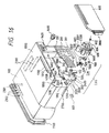
- Figs. 16 to 19 illustrate an ink jet head unit IJU, an ink jet head IJH, an ink tank IT, an ink jet head cartridge IJC according to the present invention. Then, description will be made about elements with reference to the drawings.
- the ink jet cartridge IJC is arranged in such a manner that the proportion the portion for accommodating ink is enlarged as can be understood from a perspective drawing shown in Fig. 17. Therefore, the shape is made such that the front end portion of the ink jet head unit IJU projects over the front surface of the ink tank IT by a certain small degree.
- the above-described ink jet head cartridge IJC is secured and supported by a locating means to be described later and an electric contact of a carriage HC (18) mounted on an ink jet recording apparatus body IJRA.
- the same is formed into a disposable type such that it can be attached/detached from the above-described carriage HC. Since Figs. 16 to 19 illustrate the structure to which a plurality of novel technologies found during the establishment of the present invention are applied, the overall structure of the present invention will now be described while briefly describing the above-described structures.
- the ink jet head unit IJU is a unit for performing recording by using an electrothermal converting member for, in response to an electric signal, generating thermal energy with which ink is film-boiled.
- reference numeral 100 represents a heater board constituted in such a manner that electrothermal converting members (a discharging heater) formed into a plurality of lines and electric circuits such as A1 for supplying electric power are formed on an Si substrate by a film forming technology.
- Reference numeral 200 represents a circuit board which corresponds to the heater board 100, the circuit board 200 having a circuit (it is connected by, for example, a wire bonding) which corresponds to the circuit of the heater board 100 and a pad 201 disposed at the end portion of the above-described circuit and acts to receive an electric signal supplied from the body of the apparatus.
- Reference numeral 1300 represents a grooved ceiling plate on which insulating walls for sectioning a plurality of ink passage and common liquid chamber for accommodating ink to be supplied to each ink passage and the like are formed.
- the grooved ceiling 1300 is manufactured by integrally forming an ink receiving port 1500 for receiving ink supplied from the ink tank IT to introduce it into the above-described common liquid chamber and an orifice plate having a plurality of discharge ports which corresponds to the ink passages.
- the material for the integrally formed member it is preferable that polysulfone be employed. However, another molding resin may be employed.
- Reference numeral 300 represents a supporting member made of, for example, of metal and acting to support the reverse side of the circuit board 200 by the plane thereof, the supporting member 300 being made to be bottom plate of the ink jet head unit.
- Reference numeral 500 represents a retaining spring formed into an M-shape so as to press the common liquid chamber at the central portion of the M-shape retaining spring with a light pressure. Furthermore, the retaining spring 500 concentrically presses a portion of the liquid passage by its front hung portion 501, preferably it presses the region adjacent to the discharge port with linear pressure.
- the heater board 100 and the ceiling plate 1300 are fastened to each other in such a manner that the leg portion of the retaining spring passes through a hole 3121 formed in the supporting member 300 to be fastened to the reverse side of the supporting member 300.
- the heater board 100 and the ceiling plate 1300 are pressed and secured to each other by concentrated urging force of the retaining spring 500 and its front hung portion 501.
- the supporting member 300 comprises locating holes 312, 1900 and 2000 to be engaged to projections 1012 for locating the ink tank IT and locating/fusion-remaining projections 1800 and 1801.
- it comprises, on the reverses side thereof, projections 2500 and 2600 for locating the carriage HC of the apparatus body IJRA.
- the supporting member 300 has a hole 320 through which an ink supply pipe 2200 (to be described later) which enables ink to be supplied from the ink tank is passes.
- the circuit board 200 is fastened to the supporting member 300 by adhesion or the like.
- the supporting member 300 has recessed portions 2400 formed adjacent to the locating projections 2500 and 2600.
- the recessed portions 2400 are formed on extension points at the front end portions of the head the three sides of which are formed by parallel grooves 3000 and 3001. As a result, unnecessary substance such as dust or ink or the like do not reach the projections 2500 and 2600.
- a cover member 800 in which the above-described parallel groove 3000 is formed is, as shown in Fig. 19, forms an outer wall of the ink jet head cartridge IJC and as well as forms a space in which the ink jet head unit IJU is accommodated in association with the ink tank.
- An ink supply member 600 in which the parallel groove 3001 is formed is arranged in such manner that an ink conducting pipe 1600 to be connected to the above-described ink supply pipe 220 is formed while making the portion adjacent to the supply pipe 2200 to be a fixed cantilever.
- a sealing pin 602 is inserted for the purpose of maintaining the capillary between the fixed side of the ink conducting pipe and the ink supply pipe 2200.
- Reference numeral 610 represents a packing for establishing a sealed state between the ink tank IT and the supply pipe 2200.
- Reference numeral 700 represents a filter disposed at an end portion of the supply pipe adjacent to the tank.
- the above-described ink supply member 600 is manufactured by molding, a satisfactory accuracy can be realized while reducing the cost and the deterioration in the accuracy during the forming process can be prevented.
- the cantilever type conducting pipe 1600 is employed, the state of contact of the conducting pipe 1600 with the above-described ink receiving port 1500 can be stabled even if a mass-production method is employed. According to this embodiment, simply by introducing the sealing adhesive agent from the ink supply member, a further perfect communication state can reliably be realized.
- the ink supply member 600 can easily be secured to the supporting member 300 in such a manner that reverse side pins (omitted from illustration) of the ink supply member 600 with respect to the holes 1901 and 1902 formed in the supporting member 300 are projected through the holes 1901 and 1902 and as well as the portions projecting over the surface of the reverse side of the supporting member 300 are welded by heat.
- the small projection regions on the reverse portion welded by heat can be accommodated in a recessed portion (omitted from illustration) formed on the wall surface of the ink tank IT which is fastened to the ink jet head unit IJU. Therefore, the unit IJU can be accurately located.
- the ink tank comprises a cartridge body 1000, an ink absorbing member group 900 to be described later and cover member 1100 for sealing the ink absorbing member group 900 after it has been inserted into a side surface of the cartridge body 1000 opposing the surface of the cartridge body 1000 which is fastened to the above-described unit IJU.
- Reference numeral 900 represents the absorbing member group for impregnating ink and disposed in the cartridge body 1000.
- Reference numeral 1200 represents a supply port for supplying ink to the unit IJU composed of the above-described elements 100 to 600.
- ink can be supplied through a port communicated with atmospheric air and the above-described supply port.
- the above-described method is extremely effective in view of practical use.
- the above-described rib 2300 has, on the rear surface of the body 1000 of the ink tank, four parallel ribs in a direction in which the carriage is moved so that adhesion of the absorbing member to the rear surface is prevented. Furthermore, the partial ribs 2400 and 2500 are formed on the inner surface of the cover member 1100 present on the extension line which corresponds to the rib 2300. However, each of the partial ribs 2400 and 2500 is sectioned into pieces in a manner different from the rib 2300. Therefore, the space, in which air is able to be present, can be enlarged in comparison to that realized by the above-described rib 2300.
- Reference numeral 1401 represents the atmospheric air communication port formed in the cover member for establishing a communication between the inside Portion of the cartridge and the atmospheric air.
- Reference numeral 1400 represents liquid repellent material disposed in the atmospheric air communication port 1401 so that ink leakage from the atmospheric air communication port 1401 can be prevented.
- the above-described ink accommodating space in the ink tank IT is formed into a rectangular shape arranged in such a manner that its longer side is arranged to be the side surface. Therefore, an excellent effect can be obtained from the above-described rib configuration.
- its longer side is arranged to be present in the direction in which the carriage is moved or in a case of a cubic ink tank accommodating space, it is necessary to form a rib on the overall body of the cover member 1100 so that the ink supply can be stabled.
- the inside ribs of the ink tank IT according to this embodiment are substantially uniformly distributed in the direction of the thickness of the rectangular parallelopiped ink absorbing member.
- the above-described structure is an essential factor to make the atmospheric pressure distribution to be uniform with respect to the total ink consumption in the absorbing member and thereby the residual quantity of the ink can substantially be eliminated. Then, the technological idea about the distribution of the ribs made as described above will now be described.
- the position of the atmospheric air communication port formed in the tank is not limited to that arranged according to this embodiment if it is formed at a position which enables atmospheric air to be introduced into the region in which the ribs are disposed.
- the rear surface of the ink jet head cartridge IJC confronting the head is flattened so as to minimize the space required when it is mounted on the apparatus. Furthermore, the structure is arranged in such a manner that the capacity of ink can be enlarged as much as possible. Therefore, excellent effects can be obtained in that the size of the apparatus can be reduced and as well as the required number of times of interchanging the cartridge can be reduced. Furthermore, the rear portion of the space formed for the purpose of integrating the ink jet head unit IJU is utilized to form a projection portion for the atmospheric communicating port 1401. In addition, the inner portion of the above-described projection portion is formed into a hollow shape so as to form therein the atmospheric pressure supply space 1402 which corresponds to the overall thickness of the above-described absorbing member 900.
- the atmospheric pressure supply space 1402 has a considerably larger size in comparison to the conventional space and as well as the atmospheric air communicating port 1401 is disposed in the upper portion, the atmospheric pressure supply space 1402 is able to temporarily hold ink even if ink is removed from the absorbing member. Therefore, ink can reliably be recovered by the absorbing member so that an excellent cartridge in which ink can be efficiently be used can be provided.
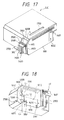
- Fig. 6 The structure of the surface of the ink tank IT to be fastened to the above-described unit IJU is shown in Fig. 6. Assuming that a straight line passing through the substantial center of the projection port of the orifice plate 400 and as well as running in parallel to the bottom surface of the tank IT or the mounting reference plane on the surface of the carriage is L 1 , the two locating projections 1012 to be engaged to the holes 312 formed in the supporting member 300 are positioned on the straight line L 1 . The height of the projection 1012 is slightly lower than the thickness of the supporting member 300 so that the supporting member 300 can be located. Referring to Fig.
- the structure is arranged in such a manner that a claw 2100, to which an engagement surface 4002 the angle of which is 90° of a carriage locating hook 4001 is engaged, is positioned on an extension line of the straight line L 1 so that the working force for locating the carriage acts on the plane region running parallel to the above-described reference surface including the straight line L 1 .
- the above-described relationship is an effective structure because the locating accuracy for only the ink tank can be made to be the same as the locating accuracy of the discharge port formed in the head.
- the projections 1800 and 1801 of the ink tank corresponding to fixing holes 1900 and 2000 to fix the supporting member 300 to the side surface of the ink tank are made to be longer than the above-described projection 1012. As a result, they penetrate the supporting member 300 and the portion projecting over it is fused with heat so that the supporting member 300 is fixed to the side surface of the ink tank. Assuming that a straight line running perpendicular to the above-described line L1 and passing through the above-described projection 1800 is L 3 and that passing through the projection 1801 is L 2 , the substantial center of the above-described supply port 1200 is positioned on the straight line L 3 . Therefore, the status of connection established between the supply port 1200 and the supply pipe 2200 can be stabled.
- a curve L 4 designates the position of the outer wall when the ink supply member 600 is fastened. Since the projections 1800 and 1801 are formed along the curve L 1 , satisfactory large strength and position accuracy can be obtained against weight of the front end structure of the head IJH.
- Reference numeral 2700 represents a front flange of the ink tank IT to be inserted into a hole formed in a front plate 4000 of the carriage.
- Reference numeral 2101 represents a stopper provided with respect to the carriage HC, the stopper being provided for a bar (omitted from illustration) of the carriage HC.
- the stopper 2101 is introduced into a portion below the bar at this position. As a result, it serves as a protection member acting to maintain the state of fastening even if upward force which causes undesirable removal from the located position acts.
- the ink tank IT covers the cover 800 after the unit IJU has been fastened to it so that it is formed into a shape which surrounds the unit IJU except for the downward opening.
- the ink jet cartridge IJC is arranged in such a manner that its downward opening, with which the ink jet cartridge IJC is mounted on the carriage HC, is positioned adjacent to the carriage HC. Therefore, a space, the four directions of which are substantially surrounded, is formed. Therefore, heat generated from the head IJH disposed in the above-described surrounded space causes an effect of maintaining the temperature in the above-described space to be obtained. However, the temperature slightly rises if the apparatus is used continuously for a long time.
- this embodiment is arranged in such a manner that a slit 1700 the width of which is smaller than the above-described space is formed above the cartridge IJC in order to cause the supporting member to smoothly naturally emit heat.
- a slit 1700 the width of which is smaller than the above-described space is formed above the cartridge IJC in order to cause the supporting member to smoothly naturally emit heat.
- ink jet head cartridge IJC When the ink jet head cartridge IJC is assembled, ink is supplied to the inner portion of the supply tank 600 from the inside portion of the cartridge via the supply port 1200, the hole 320 formed in the supporting member and an introduction port formed in the reverse side of the intermediate portion of the supply tank 600. After ink has passed through the inner portion of the supply tank 600, it is introduced through a discharge port into the common liquid chamber via proper supply pipes and the ink introduction port 1500 formed in the ceiling plate 400.
- packings each of which is made of, for example, silicon rubber or butyl rubber are disposed so that a sealing effect is obtained and thereby the ink supply passage is formed.
- the ceiling plate 1300 is made of a resin displaying excellent ink resistance such as polysulfone, polyether sulfone, polyphenylene oxide and polypropylene and integrally and simultaneously molded with the orifice plate portion 400 in a mold.
- the ink supply member 600, the ceiling plate and the orifice plate integrated and the ink tank body 1000 are integrally formed members. Therefore, the assembling accuracy can be improved and as well as a significant advantage can be realized when a mass production process is employed. In addition, the number of elements can be reduced in comparison to that required in the conventional apparatus. As a result, desired characteristics can be reliably realized.
- this embodiment is arranged in such a manner that the ink supply member 600 has a top surface portion 603 which, as shown in Fig. 17, forms slit S in association with an end portion 4008 of the roof portion having the slit 1700 formed in the ink tank IT.
- a lower surface portion 604 forms a slit (omitted from illustration), which is similar to the above-described slit S, in association with a head end portion 4011 of a thin plate member to which the lower cover 800 of the ink tank IT.
- the slits formed between the ink tank IT and the ink supply member 600 act to substantially improve the effect of causing heat of the above-described slit 1700 to be emitted.
- even if unnecessary pressure is applied to the tank IT direct apply of the pressure to the supply member is prevented and therefore apply of the same to the ink jet unit IJT is prevented.
- any one of the structures according to this embodiment is structured in a novel manner and as well as an effect can be obtained from any one of the structures. Furthermore, in a case where they are combined with one another, an effect can be obtained.
- reference numeral 5000 represents a platen roller which upwards guides recording medium P from the lower portion of the sheet.
- the carriage HC moves along the platen roller 3000 and comprises a front plate 4000 (thickness: 2 mm) formed in the front portion of the carriage adjacent to the platen such that it is positioned to confront the front surface of the ink jet cartridge IJC, a flexible sheet 4005 having a pad 2011 which corresponds to a pad 201 of the circuit board 200 of the cartridge IJC, an electric connection supporting member 4003 for holding a rubber pad sheet 4007 which generates elastic force which presses the flexible sheet 4005 to each pad 2011 from the reverse side and a locating hook 4001 for securing the ink jet cartridge IJC to a recording position.
- the front plate 4000 has two locating projection surfaces 4010 to correspond to the above-described locating projections 2500 and 2600 of the supporting member 300 of the cartridge. Therefore, it receives perpendicular force applied toward the projection surface 4010 after the cartridge has been fastened.
- a reinforcing rib has a plurality of ribs (omitted from illustration) which are applied in the perpendicular direction on the portion of the front plate adjacent to the platen roller.
- the above-described rib also forms a head protecting projection portion which projects toward the platen roller by a slight degree (about 0.1 mm) over front surface position L 5 in a state where the cartridge IJC has been fastened.
- the electric connecting supporting plate 4003 has a plurality of reinforcing ribs 4004 in the perpendicular direction in place of the direction of the above-described rib in such a manner that the degree of the projection is decreased in a direction from the platen to the hook 4001.
- This arrangement of the structure acts to incline the position when the cartridge has been fastened as illustrated.
- the supporting plate 4003 has two hook-side locating surfaces 4006 to correspond to the projection surface 4010 for the purpose of giving force acting on the cartridge in a direction opposing the direction in which the above-described two locating projection surfaces 4010 acts on the cartridge so that the electrical contact state is stabilized.
- a pad contact region is formed in the thus-formed space and as well as the amount of deformation of a boss of a rubber sheet 4007 having bosses which correspond to the pad 2011 is defined.
- the above-described locating surfaces are brought into a state in which they are positioned in contact with the surface of the circuit board 3000 when the cartridge IJC has been fixed to a position at which recording can be performed.
- the pad 201 of the circuit board 300 is distributed to be symmetric with respect to the above-described line L 1 . Therefore, the amount of deformation of each boss of the rubber sheet 4007 is equalized so that the pressure level at which each boss is positioned in contact with the pads 2011 is further stabilized.
- the pads 201 are distributed such that two columns are arranged in both the upper and the lower portions and two columns are arranged longitudinally.
- the hook 4001 has an elongated hole to be engaged to a fixed shaft 4009 so as to rotate counterclockwise from the illustrated position by utilizing the movable space realized by the above-described elongated hole. Then, the hook 4001 is moved to left along the platen roller 5000 so that the ink jet cartridge IJC is located with respect to the carriage HC.
- the present invention is not limited to the way of the movement of the hook 4001. However, it is preferable that a structure be employed which is arranged in such a manner that the movement can be performed by means of a lever or the like.
- the locating projections 2500 and 2600 are moved to positions at which they are able to come in contact with the locating surface 4010 of the front plate while moving the cartridge IJC to the platen roller.
- a 90°-hook surface 4002 causes the cartridge IJC to rotate in a horizontal plane while making the contact region between the locating surfaces 2500 and 4010 to be the center while coming contact with the 90°-place of the claw 2100 of the cartridge IJC.
- the pads 201 and 2011 come in contact with each other.
- the hook 4001 When the hook 4001 is held at a predetermined position, that is, the position at which the same must be fixed, the perfect contact between the pads 201 and 2011, the perfect contact between the locating surfaces 2500 and 4010, the two planes contact between the 90°-surface 4002 and the 90°-surface of the claw and the surface contact between the circuit board 300 and the locating surface 4006 are simultaneously realized. As a result, the cartridge IJC is held with respect to the carriage.
- Fig. 1 is an exploded perspective view which illustrates the schematic structure of a recording head according to an embodiment of the present invention.
- the ceiling plate 1300 has a plurality of ink discharge ports, liquid passages communicating with the ink discharge ports and a groove for forming a common liquid chamber commonly communicated with each liquid passage. Furthermore, the ceiling plate 1300 has a hole for forming the ink receiving port 1500 formed at the position which corresponds to the common liquid chamber and a projection 1500a.
- the heater board 100 has electrothermal converting members serving as the discharge energy generating devices at positions corresponding to the provided liquid passages.
- the ink supply passage member 600 has an ink passage 623 for supplying ink from the ink tank to the ink receiving port 1500.
- Fig. 2 is a front elevational view which illustrates each of the above-described elements.
- Fig. 3 is a cross sectional view which illustrates a portion including the ink receiving port 1500 having the ceiling plate 1300 which is the connecting portion to be connected to the ink jet head portion.
- a burr-like deformable annular projection 1500b the width b of which is about 0.005 to 0.1 mm and the height a of which is about 0.01 to 0.2 mm is integrally formed on the top surface of the projection 1500a which constitutes the receiving port 1500.
- Fig. 4 is a front elevational view which illustrates a state in which the ink supply passage member 600 and the recording head are fastened to each other.
- Fig. 5 is a cross sectional view which illustrates the connection established between the projection 1500a and the connecting portion of the ink supply passage member 600 in the above-described state.
- the ink supply passage member 600 is caulked by heat at its surface to be connected to the supporting member 600 so that it is secured to the surface of the supporting member 300. At the time of the heat caulking, the ink supply passage member 600 is brought into contact with the ceiling plate 1300. As a result, the annular projection 1500b of the ceiling plate 1300 is crushed so that the ink supply passage member 6000 and the projection 1500a of the ink receiving port 1500 are brought into contact with each other in a hermetical manner.
- the force for deforming the annular projection 1500b is about 100 to 300 g according to this embodiment.
- the ink supply passage member 600 is a resin molded element, it is difficult to completely form the ink passage 623 by only molding due to the limitation present in the structure of the mold. Therefore, a plug 602 is press-fit into the ink passage 623 so that the ink passage is formed. An end portion of the ink passage 623 at which the filter 700 is disposed is arranged to introduce ink placed in the ink tank when it is pressed to foam material which contains ink in the ink tank.
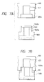
- Fig. 6 is a cross sectional view which illustrates the ink supply passage member and the ceiling plate according to another embodiment of the present invention.
- the annular projection 600b which is crushed at the time of the connection operation is formed adjacent to connecting portion of the ink supply passage member 600.
- the surface of the member 600 on which the projection 600b is formed is recessed by a certain degree from the surface at which the supporting member 300 is connected. Therefore, it can be easily handled because it is not easily deformed at the time of the manufacturing process or the like in comparison to the case in which the annular projection 1500B is formed on the ceiling plate 1300 according to the above-described embodiment.
- both of the projection 600b and the projection 1500b are formed in such a manner that they do not interfere with each other and as well as each of them are crushed at the time of the connection, resulting a satisfactory effect to be obtained in terms of improving the adhesion.
- Figs. 7A and 7B illustrate a modification to the structure shown in Fig. 2.
- a fastening portion 600a is formed in the ink supply passage member 600, the fastening portion 600a being fastened to the projection 1500a of the receiving port 1500.
- a relative large quantity of a sealant 399 can be used in the state of the connection shown in Fig. 17B.
- the distance between the connecting portion between the ink supply passage member 600 and the ceiling plate 1300 and outer air is increased so that air cannot be introduced into the ink supply passage.
- a sealer having elasticity such as a silicon type sealer and a urethane type sealer
- Figs. 8A and 8B illustrate a modification to the structure shown in Fig. 7.
- the fastening portion 600a has a tapered portion 600c.
- it can be brought into contact with a portion of the side surface of the projection 1500a of the ceiling plate 1300 in a hermetical manner after it has been fastened to the ceiling plate 1300. Therefore, the adhesion can further be improved in addition to the effect realized by the adhesion with the annular projection 1500b.
- the structure shown in Fig. 8 be arranged in such a manner that the connecting portion be sealed by the sealer 399 similarly to the structure shown in Fig. 7.
- annular projection 1500b or 600b at the time of forming the ceiling plate or the ink supply passage member can be eliminated. That is, the annular projection may be formed by utilizing burrs generated in the opening portion of the ink receiving port 1500 or that of the ink passage 623 when the ceiling plate or the like is formed.
- the structure shown in Figs. 7 and 8 may be arranged in such a manner that the projection portion is formed adjacent to the ink supply passage member similarly to the structure shown in Fig. 6.
- the free end portion of the cantilever type conducting pipe must be capable of moving.
- the portion at which the ink supply passage member comes in contact with the recording head must be sealed at the time of working the ink sucking function or the like.
- the size of the ink supply passage member can be reduced.
- the ink supply passage member is made of a resin, the mold can be simplified and the same can be manufactured with low cost.
- the projection portion can be formed from the burrs or the like generated at the time of performing molding by using a resin. Therefore, the projection portion can be formed while eliminating a necessity of performing a special process.
- the movable portion can be omitted from the ink supply passage member, causing effects to be obtained in that the size of the supply passage member can be reduced and the mold for manufacturing it can be produced at low cost. As a result, the overall cost of the ink jet recording head can be reduced.
- the deformed portion is able to come in contact with the entire surface, another effect can be obtained in that ink leakage and undesirable introduction of the sealer can be prevented. As a result, the reliability can be improved.
- a preferable sealer according to this embodiment for use in a portion which establishes a connection between the recording head and the ink supply passage member, in the ink jet head (IJH) portion and in its adjacent portion will now be described with reference to a case in which the ink jet head (IJH) portion and its adjacent portion are sealed.
- the ink jet head comprises a substrate 1 (hereinafter called a “heater board") on which an ink discharging pressure generating device is formed, a liquid chamber 7 connected to the substrate 1 and accommodating recording medium (hereinafter called “ink”) and a substrate 2 having projection and recessed portions which constitute an ink passage 8.
- the above-described substrate 2 integrally has an orifice plate 4 (hereinafter called a “grooved ceiling plate”) which has ink discharge port 9 communicated with the ink passage 8 and acting to discharge ink.
- the heater board 1 is allowed to adhere to a supporting substrate 3 by an adhesive agent, while the grooved ceiling plate 2 is disposed on the surface of the heater board 1 in such a manner that a heater portion disposed on the heater board 1 and serving as an ink discharging pressure generating device coincides with the ink passage 8 formed in the grooved ceiling plate 2. Furthermore, the orifice plate 4 which is the grooved ceiling plate is disposed on the front surface of the supporting substrate 3 in such a manner that it is downwards hung.
- Ink is supplied from an ink supply member 5 after it has passed through an ink supply port 2a formed in the upper portion of the grooved ceiling plate.
- the ink supply member 5 has a projection rod which is inserted into a through hole formed in the supporting substrate before they are caulked by heat so that the ink supply member 5 is secured to the supporting substrate.
- the sealer is introduced into small gaps 10a and 10b between the ink supply member 5, the heater board 1 and the grooved ceiling plate 2 and the like. Furthermore, the same is introduced into an adhesive space in the connecting region to which the adhesive agent is introduced and which has small gaps formed between the orifice plate and the front surface of the supporting substrate.
- the thickness of a portion adjacent to the discharge portion formed in the orifice plate 4 which constitutes the ink jet head is about 30 to 40 ⁇ m. It is preferable that it be increased in a direction toward the lower portion of the supporting substrate 3. The same is made to be 0.2 mm according to this embodiment.
- the grooved ceiling plate 2 having the orifice plate 4 may be made of thermal plastic resin such as polyimide, polyethyletherketone, polysulfone or the like.
- Fig. 10 is a front elevational view which illustrates the ink jet head. Referring to Fig. 10, the diagonal-line portion shows a region filled with the sealer.
- the supporting substrate 3 has grooves 3A formed on the two sides thereof. As shown in Fig. 11, this embodiment is arranged in such a manner that the groove 3A is made such that its width is 1 mm and the depth is 0.2 mm.
- the present invention is not limited to the above-described size of the groove 3A if the groove is formed such that the sealer can be satisfactorily enclosed into the same.
- the heater board is secured to the surface of the supporting substrate 3 by an adhesive agent and as well as the grooved ceiling plate 2 is secured by mechanical urging force realized by a retaining spring 6 temporarily fastened to the surface of the heater board 1 by an adhesive agent in such a manner that the heater portion disposed on the heater board 1 coincides with the ink passage 7 formed in the grooved ceiling plate 2.
- the grooved ceiling plate 2 has the orifice plate 4 in such a manner that the orifice plate 4 is disposed to hang at the front surface of the supporting substrate 3.
- the ink supply member 5 is secured to the supporting substrate 3 in such a manner that a projection rod (omitted from illustration) formed on the ink supply member is made coincide with a through hole formed in the supporting substrate 3 before they are caulked by heat.
- uniform gaps 10a and 10b are formed between the orifice plate 4 and the ink supply member 5. According to this embodiment, each of the gaps 10a and 10b is made to be 0.1 to 0.2 mm.
- the groove 3A formed in the supporting substrate 3 must form a space which is continued from the gap formed between the orifice plate 4 and the ink supply member 5. It is not preferable that the groove 3A is perfectly covered by the orifice plate 4 or that the same is individually formed from the above-described gaps 10a and 10b. The reason for this lies in that the passage through which the injected sealer is disconnected or satisfactory sealing cannot be realized.
- the groove 3A in the front surface of the supporting substrate 3 is formed by pressing in terms of necessity that it must be manufactured by mass production.
- the sealer is injected through the sealer injection port (omitted from illustration) formed in the upper portion of the ink supply member 5 so that the wire bonding portion 11 for transmitting an electric signal is sealed and as well as the gaps 10a and 10b between the orifice plate 4 and the ink supply member 5 are sealed. Then, the sealer passes through the groove 3A formed in the supporting substrate 3 so that the gap region between the orifice plate 4 and the front surface of the supporting substrate 3 is perfectly sealed. It is necessary for the sealer to seal the gap in such a manner that it does not cover the orifice 9, proper thixotropy and viscosity.
- the viscosity of the sealer is too low, the same can be introduced into the nozzle and the orifice disposed in the grooved ceiling plate 2, causing blinding to take place. If the same is too high, the sealer cannot satisfactorily reach the portion including the orifice plate 4.
- Table 1 shows results of examinations made about the state of the supply of the sealer and blinding taken place in the orifice plate, the nozzle and the orifice by using sealers the viscosity of which are made to be 800, 4,000, 10,000 and 18,000 cps.
- mark o designates an excellent sealer supply in the orifice plate portion and a state of no blinding in the nozzle orifice portion, while mark x designates unsatisfactory states.
- the viscosity of the sealer according to the present invention is 1,000 to 15,000 cps, preferably 2,000 to 10,000 cps, and further preferably 4,000 to 10,000 cps.
- the sealer must display excellent adhesion performed to the heater board made of silicone wafer, the supporting substrate 3 made of metal, the grooved ceiling plate 2, the orifice plate 4, and the ink supply member 5 and the like made of a synthetic resin.
- soft material capable of absorbing the difference in the thermal expansion due to the temperature status must be used.
- a sealer the hardness of which is A100 of JIS or lower must be used.
- the above-described sealer as well as acts to cover the wire bonding portion 11 to protect it, it must be made of material with which the aluminum wire bonding portion and the aluminum electrode is not corroded. In order to prevent corrosion of the electrode and the wire bonding, it is preferable that the density of impurity ions such as Cl - and Na + in the sealer be 30 ppm or less.
- the above-described material must have excellent ink resistance, and, more particularly, solution resistance and alkali resistance because it partially comes in contact with ink. In addition, it must have low permeability with respect to oxygen, nitrogen and steam.
- a urethane resin As a sealer which meets the above-described requirements, a urethane resin, an acrylic resin, a flexible epoxy resin and rubber type adhesive agent and the like may be used according to the present invention. It is further preferable that the material has elasticity of the rubber.
- a double-liquid urethane adhesive agent the composition of which is as follows, and particularly, that which has a urethane bond - NHCOO- in its molecular was used:
- Polyetherpolyol 100 parts by weight Silane coupling agent 5 parts by weight Thixotropy agent 1 part by weight Colorant 1 part by weight (Hardening Agent) Polyisocyanate 40 parts by weight
- the double-liquid urethane adhesive agent displays significantly low air permeability and steam permeability in comparison to the conventional silicon resin type adhesive agent, undesirable introduction of air into IJH can be prevented. Furthermore, evaporation of water contained in ink can be prevented.
- polyether polyol that is, polyether type polyhydric alcohol
- polyalkylene glycol such as polyethylene glycol and polypropylene glycol and the like
- polytetramethylene glycol polytetramethylene glycol
- an isocyanate trimer such as polymeric and an isocyanate dimer such as trilenediisocyanate, 4,4'-diphenylmethanediisocyanate, xylilenediisocyanate, naphthylenediisocyanate, paraphenylenediisocyanate, tetramethylxylilenediisocyanate, dicyclohexylmethanediisocyanate, isophoronediisocyanate, lysinediisocyanate, lysinediisocyanate, hydroxylilenediisocyanate, microhexyldiisocyanate and tridinediisocyanate.
- the above-described materials may be used solely or in a state in which selected materials are combined to each other.
- the mixture ratio of the above-described polyetherpolyol and polyisocyanate is made to be 100 parts by weight: 40 parts by weight according to the above-described example.
- the present invention is not limited to this. Therefor, the above-described mixture ratio may be properly determined in accordance with the equivalent ratio between the hydroxyl group (OH group) of polyol and the isocyanate group (-NCO-group) of polyisocyanate.
- aerozil may be used as the above-described thixotropy agent, the aerozil being an amorphous silica which gives excellent thixotropy characteristics to the urethane adhesive agent obtained from the above-described mixture.
- the viscosity of the double-liquid urethane adhesive agent serving as the sealer according to the present invention is adjusted to be within the above-described range by changing the molecular weight of the urethane adhesive agent which can be changed in accordance with the polymerization degree at the time of urethane reaction taken place between the polyether polyol and polyisocyanate and the quantity of thixotropy agent added. Furthermore, the viscosity can be adjusted while sufficiently dispersing the thixotropy agent to a pre-polymer obtained by pre-polymerizing mixed polyetherpolyol and polyisocyanate.
- any one of the following silane coupling agent may be used: acrylic silane such as vinyltrichlorosilane, vinyltris ( ⁇ methoxyethoxy) silane, vinyltriethoxysilane and vinyltrimethoxysilane; epoxy silane such as ⁇ -(3,4-epoxycyclohexyl) ethyltrimethoxysilane, ⁇ -glycidoxypropyltrimethoxysilane, ⁇ -glycidoxypropylmethyldiethoxysilane; amino silane such as N- ⁇ (aminoethyl) ⁇ -aminopropyltrimethoxysilane, N- ⁇ (aminoethyl) ⁇ -aminopropylmethyldimethoxysilane, ⁇ -aminopropyltriethoxysilane, N-phenyl- ⁇ -amino
- a colorant may be arbitrarily added to the above-described sealer by a quantity which is determined in accordance with the color of the desired adhesive agent.
- the colorant is exemplified by inorganic colorant such as carbon black, titanium oxide, iron oxide, chrome oxide, cadmium sulfate, aluminomagnesium and lamp black and organic colorant such as azoic dye, diazoic dye, phthalocyanine and dioxazine.
- a catalyzer may be added.
- the catalyzer may be exemplified by the following organic metal catalyzer: stannous octoate, dibutyltin diacetate, dibutyltin dilaurate, dibutyltinmercaptide, dibutyltinthiocarboxyte, dibutyltin dimaleate, dioctyltin mercaptide, dioctyltin thiocarboxylate, phenylmercuric propionate and octoate.
- Ink jet cartridges each integrally having an ink jet unit and an ink tank were mounted on the corresponding printers after the portions each including the recording head portion of the ink jet unit have respectively been sealed by a sinlge-liquid RTV silicon resin and the double-liquid urethane resin.
- the printer was allowed to stand in a dry condition the temperature of which was 35°C and the humidity of which was 20%. Then, no recovery operation was performed and an examination whether or not printing could be performed was carried out.
- the results are shown in Table 3.
- mark O designates a state where air in the unit was not introduced and printing could be performed while performing no recovery operation.
- Mark x designates a state where printing could not be performed if the recovery operation was not performed since air was introduced.
- the air permeability shown in Table 3 was shown in units of [cm 3 ][cm]/[sec][cm 2 ][cmHg].
- the permeability of air was measured by employing a gas permeability test method regulated by JIS.
- Table 3 Allowed to stand at 35°C in a dry state Sealer Air Permeability 3 days 7 days 15 days 30 days Silicone resin (KE471 manufactured by Shinetsu Chemical) about 400 x 10 -10 O x x x Double-liquid urethane resin (Ekosen manufactured by Grace Japan) about 30 x 10 -10 O O O O O O Butadiene rubber (NF35A manufactured by Asahi Kasei) about 10 x 10 -10 O O O O O O O
- the urethane resin and the butadiene rubber which display a low air permeability of the order of 10 -9 resuled an excellent printing performance even if they have been allowed to stand for 30 days in comparison to a silicon resin the air permeability of which is in the order of 10 -8 .
- sealer which displays a low steam permeability in the order of 10 -7 showed excellent results as shown in Table 4 in comparison to the slicon resin which displayed a high steam permeability in the order of 10 -6 .
- the gaps 10a and 10b between the ink supply member 5, the heater board 1 and the grooved ceiling plate 2 and the gap between the orifice plate 4 and the front surface of the supporting substrate 3 be small enough to introduce the sealer by its capillary and as well as large enough to realize a uniform introduction flow.
- the viscosity of the sealer is too low or the quantity of the sealer introduced is too large, it is undesirably discharged through the gap before it is hardened. Furthermore, there arises a risk of covering the ink discharge port 9 after it has been introduced into the connecting portion 10c between the heater board 1 and the grooved ceiling plate 2. If the viscosity is too high or the quantity of the sealer introduced is too small, it is undesirably hardened before it is introduced. Therefore, it is difficult to arrange the balance between the viscosity, the hardening time and the quantity of the sealer introduced.
- a photosetting rein is used as the sealer which is able to meet the above-described requirements.
- an ultraviolet hardening adhesive agent is used as the photosetting resin.
- the sealer is, in a state where pre-premerization flow of it is enabled, introduced through an injection port (omitted from illustration) formed in the ink supply member 5 shown in Fig. 10 into the gaps 10a and 10b formed between the wire bonding portion, orifice plate 4 and the ink supply member 5. Then, it passes through the groove 3A formed in the supporting substrate 3 before it reaches the gap region between the orifice plate 4 and the front surface of the supporting substrate 3 so as to be hardened by an ultraviolet hardening apparatus.
- the following photopolymerizing prepolymer may be used: polyesteracrylate, epoxyacrylate, polyetheracrylate, oligoacrylate, alkidaclylate, polyolacrylate, melamineacrylate, or silicon acrylate or the like.
- a photoinitiator is added to the main component of the above-described ultraviolet hardening adhesive agent by a desired quantity.
- the photoinitiator is exemplified by biacetyl, acetophenone, benzophenone, schiller ketone, benzil, benzoil, benzoinisobutylether, benzildimethylketal, tetramethylthiuram disulfide, azobisisobutylnitryl, benzoilperoxide, di-tert-butylperoxide, 1-hydroxycyclohexylphenylketone, 2-hydroxy-2-methyl-1-phenylpropane-1-on, 1 (4-isopropylphenyl)-2-hydroxy-2-methylpropane-1-on, 2-chlorothioxantone and methylbenzoyl formate.
- the grooved ceiling plate 2 be made of transparent or semitransparent material.
- the material for the grooved ceiling plate 2 is exemplified by: polysulfone, polyarylsulfone, polyethersulfone, polycarbonate, polymethacrylic acid, polyphenyleneoxide, polyarylate, ABS resin and acrylc resin.
- the direction in which the ultraviolet rays are applied be, as designated by an arrow shown in Fig. 9, made to be a direction to the orifice plate 4 and the upper opening portion 5 formed in the supply member 5.
- the ink supply member 5 is made of transparent or semitransparent material, it is necessary for the ultraviolet rays to be applied in only one direction. Therefore, the structure of the ultraviolet ray irradiating apparatus can be simplified.
- Fig. 12 illustrates another embodiment. This embodiment is arranged in such a manner that no orifice plate is provided for the grooved ceiling plate but the entire surface of the supporting substrate is covered with the ink supply member 5 and as well as a small gap 10e is formed in a space from the grooved ceiling plate 2.
- This embodiment is structured in such a manner that the sealer is introduced into all of the gaps 10, 10b and 10e formed between the ink supply member 5 and the grooved ceiling plate 2.
- the sealer introduced into the above-described gaps 10a, 10b and 10e can be hardened with ultraviolet rays even if the grooved ceiling plate 2 which appears outside is not made of the transparent or semitransparent material. Therefore, the grooved ceiling plate 2 can be made of material selected relatively freely. Furthermore, since the groove 3A can be omitted from the supporting substrate 3, the manufacturing cost can be reduced.
- Fig. 13 illustrates the appearance of an embodiment of the ink jet recording apparatus IJRA.
- a carriage HC has a pin (omitted from illustration), the carriage HC being engaged to a spiral groove 5004 formed in a lead screw 5005 which is rotated in synchronization with the forward/rearward rotation of a drive motor 5013 via drive force transmitting gears 5011 and 5009 so that it is reciprocated in directions respectively designated by arrows a and b.
- Reference numeral 5002 represents a paper holding plate for pressing paper to the platen 5000 in a direction in which the carriage HC move.
- Reference numerals 5007 and 5008 represent photocouplers each of which is a home position detection means for confirming the presence of a lever 5006 of the carriage HC in the above-described region to switch the rotational direction of a motor 5013 or the like.
- Reference numeral 5016 represents a member for supporting a cap member 5022 which caps the front surface of a recording head.
- Reference numeral 5015 represents a sucking member for sucking the recording head in the above-described cap, the sucking member performing sucking and recovering the recording head via an opening 5023 in the cap.
- Reference numeral 5017 represents a cleaning blade and 5019 represents a member for enabling the above-described blade 5017 in the longitudinal direction.
- the above-described members are supported by a body supporting plate 5018.
- Reference numeral 5012 represents a lever for commencing sucking for recovering the recording head, the lever 5012 being moved when a cam 5020 which is engaged to the carriage HC is moved.
- Drive force supplied from a drive motor is transmitted from a known transmitting means such as a clutch.
- the above-described capping operation, the cleaning operation and sucking operation for recovering the recording head are arranged to be performed at corresponding positions by an action of the lead screw 5005 when the carriage HC has been brought into the home position region.
- all of the above-described operations can be applied to this embodiment by arranging the structure in such a manner that a desired operation is performed at a known timing.
- Each of the above-described structures is an excellent invention if it is employed solely or combined to each other so that an excellent effect can be obtained when it is employed in this embodiment.
- the apparatus according to this embodiment has a control portion for transmitting a drive signal for driving the recording head mounted.
- Fig. 14 is a perspective view which illustrates an example of the structure of a printer which is able to use the head cartridge according to the above-described embodiments of the present invention.
- Reference numeral 9 represents a head cartridge which is able to comprise the ink jet head unit according to the present invention.
- Reference numeral 11 represents a carriage on which the head cartridge 9 is mounted and which performs scanning operation in direction designated by symbol S shown in Fig. 14.
- Reference numeral 13 represents a hook for fastening the head cartridge 9 to the carriage 11.
- Reference numeral 15 represents a lever for operating the hook 13. The lever 15 has a marker 17 for indicating a scale provided for a cover to be described later so that the printing position performed by the recording head or the setting position and the like are read.
- Reference numeral 19 represents a supporting plate for supporting an electrical connecting portion to be connected to the head cartridge 9.
- Reference numeral 21 represents a flexible cable for establishing a connection between the above-described electric connecting portion and the body control portion. A drive signal transmitted from the control portion disposed in the apparatus body is supplied to the recording head according to the present invention via the above-described flexible cable so that the recording head is driven.
- Reference numeral 23 represents a guide shaft for guiding the carriage in the direction S, the guide shaft 23 being inserted into a bearing 25 of the carriage 11.
- Reference numeral 27 represents a timing belt to which the carriage 11 is secured and which transmits power to move the carriage 11 in the direction S.
- the timing belt 27 is arranged between pulleys 29A and 29B disposed on the two side portions of the apparatus.
- the pulley 29B is given drive force from a carriage motor 31 via a power conducting mechanism such as a gear.
- Reference numeral 33 represents a conveyance roller for controlling the recording side of a recording medium (hereinafter also called “recording sheet”) and as well as conveying the recording medium at the time of the recording operation or the like.
- the conveyance roller 33 is driven by a conveyance motor 35.
- Reference numeral 37 represents a paper tray for introducing the recording medium from a paper-supply tray 4 to the recording position.
- Reference numeral 39 represents a feed roller disposed in a paper feeding passage and for pressing the recording medium to the conveyance roller 33 for the purpose of conveying the recording medium.
- Reference numeral 34 represents a platen disposed to confront the discharge port formed in the cartridge 9 to control the recording side of the recording medium.
- Reference numeral 41 represents a paper discharging roller disposed at a position in the lower stream from the recording position on the passage through which the recording medium is conveyed, the discharging roller 41 acting to discharge the recording medium to the discharge port (omitted from illustration).
- Reference. numeral 42 represents a spur disposed to correspond to the paper discharging roller 41, the spur 42 pressing the roller 41 via the recording medium so that the paper discharge roller 41 generates force for conveying the recording medium.
- Reference numeral 43 represents a release lever for releasing the urging force generated by the feed roller 39, the retaining plate 45 and the spur 42 at the time of setting of the recording medium.
- Reference numeral 45 represents a retaining plate for restricting floating of the recording medium at a position in the vicinity of the recording position so as to realize a state in which the recording medium comes in contact with the conveyance roller 33 in a hermetical manner.
- an ink jet recording head of a type which discharges ink is employed as the recording head. Therefore, it is effective to dispose the retaining plate 45 because the distance between the surface of the recording head in which the ink discharge port is formed and the recording surface is small and the same must be strictly controlled for the purpose of preventing the contact between the recording medium and the surface in which the discharge port is formed.
- Reference numeral 47 represents a scale provided on the retaining plate 45.
- Reference numeral 49 represents a marker provided on the carriage 11 to correspond to the above-described scale 47. The printing position and the setting position of the recording head can also be read by the above-described elements.
- Reference numeral 51 represents a cap disposed to correspond to the surface of the recording head in which the ink discharge port is formed at the home position and made of elastic material such as rubber.
- the cap 51 is supported in such a manner that it is able to come in contact/move away from the recording head.
- the above-described cap 51 acts to protect the recording head when no recording is performed or when an operation of recovering the discharging operation of the recording head.
- the "discharging operation recovering operation” an action arranged in such a manner that the cap 51 is made to confront the surface in which the discharge port is formed to drive an energy generating element disposed inside of the ink discharge port so as to generate energy for discharging ink.
- ink is discharged from the discharge port so that ink which cannot be used to perform recording due to bubble, dust and viscosity raised excessively and the like is discharged (previous discharge for removing a defective factor). Furthermore, ink is forcibly discharged from the discharge port while making the cap 5 cover the surface in which the discharge port is formed to remove the defective factor.
- Reference numeral 53 represents a pump for generating suction force for forcibly discharging ink and sucking ink received in the cap 51 at the time of the discharge recovery operation by the forcible discharge or the discharge recovery operation by the previous discharge.
- Reference numeral 55 represents an waste ink tank or accumulating waste ink sucked by the pump 53 and 57 represents a tube for establishing a communication between the pump 53 and the waste ink tank 55.
- Reference numeral 59 represents a blade for wiping the surface of the recording head in which the discharge port is formed, the blade 59 being supported in such a manner that it can be moved between a position at which wiping is performed during the movement of the head while projecting toward the recording head and a retracted position at which it is not engaged to the surface in which the discharge port is formed.
- Reference numeral 61 represents a motor and 63 represents a cam unit which receives power supplied from the motor 61 and which drive the pump 53 and move the cap 51 and the blade 59.
- the ink jet head cartridge to be mounted on the recording apparatus may be arranged in such manner that the ink tank and the ink jet head unit are integrally formed or they are able to separate from each other.
- the present invention brings about excellent effects particularly in a recording head, recording device of ink jet system utilizing heat energy among the ink jet recording system.
- the on-demand type is effective because, by applying at least one driving signal which gives rapid temperature elevation exceeding nucleus boiling corresponding to the recording information on an electricity-heat converters arranged corresponding to the sheets or liquid channels holding liquid (ink), heat energy is generated at the electricity-heat converters to effect film boiling at the heat acting surface of the recording head, and consequently the bubbles within the liquid (ink) can be formed corresponding one by one to the driving signals.
- the constitution of the recording head in addition to the combination constitutions of discharging orifice, liquid channel, electricity-heat converter (linear liquid channel or right angle liquid channel) as disclosed in the above-mentioned respective specifications, the constitution by use of U.S. Patent 4,558,333, 4,459,600 disclosing the constitution having the heat acting portion arranged in the flexed region is also included in the present invention.
- the present invention can be also effectively made the constitution as disclosed in Japanese Patent Laid-Open Application No. 59-123670 which discloses the constitution using a slit common to a plurality of electricity-heat converters as the discharging portion of the electricity-heat converter or Japanese Patent Laid-Open Application No. 59-138461 which discloses the constitution having the opening for absorbing pressure wave of heat energy correspondent to the discharging portion.
- the recording head of the full line type having a length corresponding to the maximum width of recording medium which can be recorded by the recording device
- either the constitution which satisfies its length by combination of a plurality of recording heads as disclosed in the above-mentioned specifications or the constitution as one recording head integrally formed may be used, and the present invention can exhibit the effects as described above further effectively.
- the present invention is effective for a recording head of the freely exchangeable chip type which enables electrical connection to the main device or supply of ink from the main device be being mounted on the main device, or for the case by use of a recording head of the carriage type provided integrally on the recording head itself.
- a restoration means for the recording head, a preliminary auxiliary means, etc. provided as the constitution of the recording device of the present invention is preferable, because the effect of the present invention can be further stabilized.
- Specific examples of these may include, for the recording head, capping means, cleaning means, pressurization or aspiration means, electricity-heat converters or another heating element or preliminary heating means according to a combination of these, and it is also effective for performing stable recording to perform preliminary mode which performs discharging separate from recording.
- the present invention is extremely effective for not only the recording mode only of a primary color such as black etc., but also a device equipped with at least one of plural different colors or full color by color mixing, whether the recording head may be either integrally constituted or combined in plural number.
- ink jet recording apparatus in addition to what is used as image output terminal of a data processing apparatus such as computers, may be those of a copying apparatus combined with readers or facsimile apparatus having transmitting and receiving functions.
- a projection which is brought into contact with, for example, the connecting portion adjacent to the recording head is formed by utilizing, for example, a burr or the like formed at the time of the resin molding. Therefore, the recording head and the ink supply passage member can be brought into contact in a hermetical manner while absorbing the relative dimensional difference.
- the sealer for sealing a space from a member for covering the connecting means for establishing the connection between the IJH and the circuit portion and as well as covering the portion in the vicinity of the IJH and the fastening portion the material the air permeability of which is about 1/10 or less of the silicon resin which is employed in the conventional structure is employed. Therefore, the discharge operation can be normally performed because undesirable air introduction into the IJH can be satisfactorily prevented even if the ink jet unit is allowed to stand for a long time.
- the sealer since the material displaying a low air permeability and a low steam permeability is used as the sealer, undesirable air introduction into the head and evaporation of the solvent of the ink can be prevented. Furthermore, since the material having urethane bonds in its molecules is used as the sealer, the oxygen, nitrogen and steam permeability can be reduced. Therefore, the undesirable introduction of bubbles into the recording head can be satisfactorily prevented even if the ink jet unit is allowed to stand for a relatively long time. Therefore, the discharge of light droplets can be performed normally while eliminating a necessity of performing the recovery operation such as the operation of sucking ink. As described above, the required number of the recovery operations can be reduced as described above. Therefore, the effective quantity of ink which can be used for the recording operation can be increased. That is, the running cost per printing medium can be reduced.
- the quantity of the waste ink can be reduced, the quantity and the volume of the absorbing member for absorbing the waste ink can significantly be reduced. Therefore, the cost of the waste-ink absorbing member can be reduced and as well as the overall size of the printer can be reduced.
- the conventional IJH encounters a problem in that the normal discharge operation cannot be performed due to undesirable introduction of bubbles into the IJH if the same is allowed to stand for a predetermined time. Therefore, the conventional IJH must be arranged to act in accordance with a sequence arranged in such a manner that an automatic suction operation is performed at predetermined intervals by using a timer or the like.
- a complicated sequence of the type described above can be omitted from the structure. Therefore, the body of the printer can be simplified and the overall cost of it can be reduced because the recovering sequence can be simplified and the necessity of using a battery for the timer can be eliminated.
- the sealer does not corrode the electrode and the wire bonding. Therefore, a reliable head can be provided.
- photosetting resin is used as a sealer for sealing a space from a member for covering the connecting means for establishing a connection between the IJH and the circuit board and surrounding a portion in the vicinity of the IJH and sealing the fastening portion, the reliability of the function of the sealer can be improved and the time which will be taken to assemble the elements can be shortened. Since the time which will be taken to manufacture the apparatus can be shortened as described above, an ink jet unit, an ink jet head and an ink jet recording apparatus the cost of which can be reduced can be provided.
- the ink jet head is arranged in such a manner that the gaps and the connecting portions between the ink supply member and the grooved ceiling plate and the heater board and the like and the gap between the orifice plate and the end surface of the supporting substrate can be sealed by a photosetting resin such as the ultraviolet hardening resin at room temperature and humidity in a short time. Therefore, since the employed ultraviolet hardening resin is a single liquid type resin, the necessities of performing a measuring operation and mixture operation can be eliminated and using the solvent can be eliminated. Therefore, the facility can be simplified and thereby it can be produced in a mass production manner. Therefore, the cost of the product which uses it can be reduced.
- a photosetting resin such as the ultraviolet hardening resin at room temperature and humidity in a short time. Therefore, since the employed ultraviolet hardening resin is a single liquid type resin, the necessities of performing a measuring operation and mixture operation can be eliminated and using the solvent can be eliminated. Therefore, the facility can be simplified and thereby it can be produced in a mass production manner. Therefore, the cost of the product which
- the gap or the like between the orifice plate portion and the ink supply member can uniformly performed in a short time. Furthermore, the sealing operation can be performed by a several times of operations. Therefore, another effect can be obtained in that labor can be reduced.
- the gaps between the orifice plate and the heater board can stably be sealed. Therefore, power loss at the time of the discharge operation can be prevented and the discharge can be performed stably. Furthermore, a leakage of air through the gap between the orifice plate and the ink supply member can be prevented. As a result, the recovery operation can be performed smoothly. Consequently, an ink jet head exhibiting the above-described advantages can stably and efficiently manufactured.
Abstract
Description
- The present invention relates to an ink jet head unit for recording information by droplets discharged from a discharging port, an ink jet head cartridge having the above-described unit and an ink jet recording apparatus having the above-described head cartridge.
- More particularly, the present invention relates to an ink jet head unit, an ink jet head cartridge and an ink jet recording apparatus having a portion through which ink passes and a junction of the ink supply passage exhibiting improved sealing performance and air tightness performance.
- In order to perform a recording operation as desired in accordance with the ink jet recording method in which ink is discharged from a discharging port, air tightness must be satisfactorily secured in an ink passage and an ink supply passage.
- As shown in Fig. 15, an example of an ink jet head (hereinafter sometimes called an "IJH") for use in the ink jet recording method comprises a substrate 1 (hereinafter called a "heater board") on which an ink discharging pressure generating device is formed, a
liquid chamber 7 connected to thesubstrate 1 and accommodating a recording liquid (hereinafter called "ink") and asubstrate 2 having a recessed portion which constitutes anink passage 8. The above-describedsubstrate 2 integrally has an orifice plate 4 (hereinafter called a "grooved ceiling plate") which hasink discharge port 9 communicated with theink passage 8 and acting to discharge ink. - The
heater board 1 is allowed to adhere to a supportingsubstrate 3 by an adhesive agent, while thegrooved ceiling plate 2 is allowed to adhere to the surface of theheater board 1 in such a manner that a heater portion disposed on theheater board 1 and serving as an ink discharging pressure generating device coincides with theink passage 8 formed in thegrooved ceiling plate 2. Furthermore, theorifice plate 4, which is the grooved ceiling plate, is disposed on the front surface of the supportingsubstrate 3 in such a manner that it is downwards hung. - Ink is supplied from an
ink supply member 5 after it has passed through anink supply port 2a formed in the upper portion of the grooved ceiling plate. Theink supply member 5 has a projection rod which is inserted into a through hole formed in the supporting substrate before they are caulked by heat so that theink supply member 5 is secured to the supporting substrate. - It is necessary for an ink jet head unit of the above-described type in which the IJH is constituted by bringing the first substrate, on which the energy generating device is formed, and the second substrate having a groove, which forms the ink passage through which recording liquid passes through, into contact with each other in a hermetical manner by mechanical urging force to be arranged in such a manner that the first substrate and the second substrate are brought into perfectly contact with each other so as to be hermetically sealed from outside air. If the above-described air tightness is not realized satisfactorily, there arises a problem in that normal liquid discharge cannot be performed because ink placed in the IJH leaks outside or the pressure generated at the time of discharging the liquid droplet leaks through the ink passage or the like. However, it is extremely difficult to bring the above-described two substrates into perfectly contact with each other due to a limitation present at the time of reducing cost or the overall size because it is necessary for the accuracy of each element to be extremely improved and the mechanical urging force to be extremely enlarged.
- The above-described air tightness must, of course, be sufficiently maintained even if pressure for discharging ink is repeatedly applied.
- Furthermore, there is a necessity of sucking ink placed in the IJH by a cap member to be described later in a case where liquid cannot normally be discharged, for example, after the ink jet unit has been allowed to stand for a long time. Therefore, air tightness must be realized not only in the IJH but also the peripheral portion of the IJH.
- As a method of improving the air tightness in the vicinity of the IJH, a structure has been disclosed in Japanese Laid-Open Patent Application No. 2-121841 which is arranged in such a manner that a silicon sealer is introduced into
small gaps ink supply member 5, theheater board 1 and thegrooved ceiling plate 2 and the like. Furthermore, the same is introduced into an adhesive space in the connecting region to which the adhesive is introduced and which has small gaps formed between the orifice plate and the front surface of the supporting substrate. - Furthermore, the above-described sealer acts to seal a connecting
portion 10c for establishing a connection between theheater board 1 and the grooved ceiling plate. The same also acts to seal the connecting portion of theink supply member 5 and the connectingportion 10d to be connected to theink supply port 2a which is the connecting portion with the ink jet head. However, it is not used in a case where theink supply member 5 and thegrooved ceiling plate 2 are integrally formed. That is, the sealer is used as follows: - (1) It acts to uniformly seal a very small gap formed in a connecting region positioned between the
orifice plate 4 and the front surface of the supportingsubstrate 3 and thegaps heater board 1, the supportingsubstrate 3 and thegroove ceiling plate 2 and theink supply member 5. As a result, it forms and remains a sealed space which is sufficiently large to perform the recovery operation by sucking in order to overcome a problem of non-discharge from theink discharge port 9 due to blinding caused from solidification of dried ink or bubbles mixed into theink passage 8 or the like. - (2) It is used to seal the connecting
portion 10c between the heater board and thegrooved ceiling plate 2 and the connectingportion 10d formed between theink supply member 5 and theink supply port 2a. - Furthermore, the sealer also acts to protect the wire bonding portion for electrically connecting the printed circuit board and the IJH from mechanical force generated due to impact or drop or moisture, the printed circuit board serving as a wiring portion for supplying electric energy with which the IJH is caused to discharge liquid.
- On the other hand, the structure of the connecting portion (10d) of the ink supply passage for supplying ink to the IJH is arranged in such a manner that the force is applied to the connecting surface between the
ink supply member 5 and theink supply port 2a to improve the adhesion. Furthermore, the silicone resin sealer is used to improve the air tightness. - As an example of the above-described structure, a structure is employed in which the ink supply port of the IJH and the conducting pipe of the ink supply passage for supplying ink are brought into contact with each other in such a manner that the free end portion of the conducting pipe of the cantilever type is brought into contact with the ink supply port before the overall body is warped. As described above, force generated by deforming the members positioned adjacent to the connecting portion is usually utilized.
- However, in the above-described case in which the members are warped, there arises a risk of breakage of the member if the members are warped excessively. Therefore, the above-described member such as the conducting pipe must have a predetermined length or longer. As a result, there arises a problem in that the size of the ink supply passage member including the conducting pipe formed into the above-described structure cannot be reduced.
- In addition, since the connections of the members such as the conducting pipe and the ink receiving port brought into contact with each other are established by utilizing the warp or the like of the members, it is difficult to hermetically connect them. Furthermore, the sealer for sealing the members is undesirably introduced into the connecting portions or the ink can be allowed to leak due to the insufficient result of the sealing operation.
- On the other hand, the silicon resin is used as the sealer to be injected into the above-described IJH portion and the connecting portion of the above-described supply passage. However, since the silicon resin displays a high gas permeability of 400 x 10-10 [cm3][cm]/[sec][cm2][cmHg] with respect to air, it is undesirably introduced into the IJH in a relatively short time in an atmospheric condition of low humidity. Therefore, the normal ink discharge cannot be performed, and, worst of all, the ink passage is blocked by bubbles formed by introduced air, causing a problem to be taken place in that the ink discharge cannot be performed.
- Furthermore, since it as well as displays a high steam permeability of 4 x 10⁻⁶ [cm3][cm]/[sec][cm2][cmHg], ink which is placed at the front end portion of the nozzle and the main component of which is water can undesirably evaporated in a relatively short time. Therefore, the density of ink is raised and thereby the normal ink discharge is inhibited and, worst of all, the problem to be taken place in that the ink discharge cannot be performed.
- The above-described phenomenon shows a tendency in that it apparently arises in a state of high temperature or a state of low temperature. In order to overcome the above-described problem, a structure has been employed which is arranged in such a manner that the adhesion between the capping and the head is improved. Another structure is employed which is arranged in such a manner that material displaying a low steam permeability is employed as the material for the capping member. However, although a certain effect is obtained from the above-described structures, the degree of it has not been satisfactory. Therefore, a manual or an automatic recovery operation by means of sucking or a previous discharge for purging must be performed. In a case of the manual recovery operation, a problem takes place in that a user must frequently perform the recovery operations. In a case of the automatic recovery operation, another problem takes place in that a timer or the like for performing the automatic ink sucking sequence must be provided for the body of the printer. In addition, since the silicon resin displays a high gas permeability with respect to oxygen and nitrogen, air is undesirably introduced into the IJH in a short time and thereby the normal ink discharge operation cannot be performed. In an extreme case, the ink passage is blocked by bubbles formed by introduced air, causing the problem to be taken place in that the ink discharge cannot be performed. Therefore, the ink sucking operation must frequently be performed as the recovery operation.
- The above-described deterioration in the ink due to the undesirable introduction of air or the evaporation of the solvent of the ink becomes critical in an ink jet head unit which uses an electrothermal converting material. The reason for this lies in that the change in the ink composition considerably affects the generation of the bubbles at the time of performing the ink discharge by generating the bubbles with heat.
- The above-described problem becomes critical in a case of the IJH of the type arranged in such a manner that the two substrates are connected to each other by the mechanical urging force to form the ink passage and the common liquid chamber because the gap cannot completely be eliminated.
- The above-described recovery operation performed frequently will decrease the number of sheets which can be printed for one cartridge because ink used for the above-described recovery operation is rejected as waste ink and the same is not used in the printing operation. As a result, the running cost cannot be reduced. Furthermore, since there arises a necessity of forming a space for accommodating the waste ink, the overall size of the printer must be enlarged by a degree corresponding to the above-described required space. The above-described becomes critical in an ink jet cartridge of a type which has the ink jet unit and the ink tank formed integrally because there is a desire to minimize the capacity of the ink tank and the overall size of the printer.
- On the other hand, in a case where the material displaying low gas-permeability and a low steam permeability is used as the sealer, it corrodes the aluminum electrode or the aluminum wire bonding portion. Therefore, the above-described material cannot be used in a case where there is a risk of disconnection. That is, since aluminum is ampholytic metal, it can be corroded by acid and alkali. For example, aluminum can react on amines contained in an epoxy adhesive agent, peroxides contained in an acrylic adhesive agent, chlorine ion (Cl -), sodium ion (Na+) and potassium ion (K+) and the like.
- Furthermore, the above-described sealer for use in the wire bonding portion and the portion around the IJH, as a member for covering the IJH, must have an excellent adhesive performance with a substrate made of polysulfone, polyphenylene oxide (PPO), aluminum or silicon. In addition, the sealer must protect the wire bonding portion from impact, vibrations or atmospheric change such as the temperature or moisture change. Therefore, it must be an elastomer displaying moisture resistance.
- An object of the present invention is to provide an ink jet head unit, an ink jet head cartridge and an ink jet recording apparatus capable of normally discharging ink while preventing evaporation of ink from the recording head portion and undesirable introduction of bubbles into the recording head even if they are allowed to stand for a long time.
- Another object of the present invention is to provide an ink jet head unit, an ink jet head cartridge and an ink jet recording apparatus capable of reducing the size of the ink supply passage member and simplifying the structure of the same and as well as enabling ink to be supplied stably.
- Another object of the present invention is to provide an ink jet head unit, an ink jet head cartridge and an ink jet recording apparatus which are suitably manufactured by a mass production manner and the cost of each of which can be reduced because the reliability of the adhesion and sealed portion can be improved and the time take to complete manufacturing can be shortened.
- In order to achieve the above-described objects, according to one aspect of the present invention, there is provided an ink jet recording head unit for performing a recording operation by discharging ink, the ink jet recording head unit comprising: an ink jet head portion having an ink passage communicated with a discharge port for discharging ink and a substrate having an energy generating element for causing energy for discharging ink to act on ink present in the ink passage and supplied through an ink supply port formed in a connecting portion; and an ink supply member having a connecting portion to be connected to the ink jet head portion so as to supply ink to the ink jet head portion via the connecting portion, wherein at least the connecting portion of the ink jet head portion and the connecting portion of the ink supply member has a projection portion at a position at which it comes in contact with the corresponding connection port so that the connecting portions are respectively connected to the corresponding connecting portions by deforming and bringing the projection portions to come in contact with the connecting portions.
- In this state, it is preferable that the projection portion is formed integrally with the connecting portion.
- Furthermore, it is preferable that the connecting portion having the projection portion is made of a resin.
- Furthermore, it is preferable that the connecting portion is sealed by a sealer.
- Furthermore, it is preferable that the energy generating elements is an electro-thermal converting member for generating thermal energy to discharge ink by generating bubbles by the thermal energy.
- Furthermore, it is preferable that the sealer is material having a urethane bond in the molecular thereof.
- Furthermore, it is preferable that the sealer is made of material the air permeability of which is 40 x 10-10 [cm3][cm]/[sec][cm2][cmHg] or less.
- Furthermore, it is preferable that the sealer is made of material the steam permeability of which is 5 x 10⁻⁷ [cm3][cm]/[sec][cm2][cmHg] or less.
- According to another aspect of the present invention, there is provided an ink jet head cartridge unit for performing a recording operation by discharging ink, the ink jet recording head unit comprising: an ink jet head portion having an ink passage communicated with a discharge port for discharging ink and a substrate having an energy generating element for causing energy for discharging ink to act on ink present in the ink passage and supplied through an ink supply port formed in a connecting portion; an ink supply member having a connecting portion to be connected to the ink jet head portion so as to supply ink to the ink jet head portion via the connecting portion; an ink jet head unit arranged in such a manner that at least the connecting portion of the ink jet head portion and the connecting portion of the ink supply member has a projection portion at a position at which it comes in contact with the corresponding connection port so that the connecting portions are respectively connected to the corresponding connecting portions by deforming and bringing the projection portions to come in contact with the connecting portions; and an ink tank for supplying ink to the ink jet unit.
- In this state, it is preferable that the projection portion is formed integrally with the connecting portion.
- Furthermore, it is preferable that the connecting portion having the projection portion is made of a resin.
- Furthermore, it is preferable that the connecting portion is sealed by a sealer.
- Furthermore, it is preferable that the energy generating elements is an electro-thermal converting member for generating thermal energy to discharge ink by generating bubbles by the thermal energy.
- Furthermore, it is preferable that the sealer is material having a urethane bond in the molecular thereof.
- Furthermore, it is preferable that the sealer is made of material the air permeability of which is 40 x 10-10 [cm3][cm]/[sec][cm2] [cmHg] or less.
- Furthermore, it is preferable that the sealer is made of material the steam permeability of which is 5 x 10⁻⁷ [cm3][cm]/[sec][cm2][cmHg] or less.
- According to another aspect of the present invention, there is provided an ink jet recording apparatus for performing a recording operation by discharging ink, the ink jet recording apparatus comprising: an ink jet head unit including an ink jet head portion having an ink passage communicated with a discharge port for discharging ink and a substrate having an energy generating element for causing energy for discharging ink to act on ink present in the ink passage and supplied through an ink supply port formed in a connecting portion; and an ink supply member having a connecting portion to be connected to the ink jet head portion so as to supply ink to the ink jet head portion via the connecting portion, wherein at least the connecting portion of the ink jet head portion and the connecting portion of the ink supply member has a projection portion at a position at which it comes in contact with the corresponding connection port so that the connecting portions are respectively connected to the corresponding connecting port ions by deforming and bringing the projection portions to come in contact with the connecting portions; and a control portion for supplying a drive signal for driving the ink jet head unit.
- According to another aspect of the present invention, there is provided an ink jet head unit for performing a recording operation by discharging ink, the ink jet head unit being a recording head comprising: an ink jet head portion having an ink passage communicated with a discharge port for discharging ink and a substrate having an energy generating element for causing energy for discharging ink to act on ink present in the ink passage; and an ink supply member connected to the ink jet head portion so as to supply ink to the ink jet head portion via the connecting portion, wherein at least a portion of the ink jet head portion and at least of a portion of the ink supply portion are sealed by a sealer made of material the air permeability of which is 40 x 10-10[cm3][cm]/[sec][cm2][cmHg] or less.
- In this state, it is preferable that the energy generating elements is an electro-thermal converting member for generating thermal energy to discharge ink by generating bubbles by the thermal energy.
- Furthermore, it is preferable that the sealer is material having a urethane bond in the molecular thereof.
- Furthermore, it is preferable that the sealer contains impurities by a density of 30 ppm or less.
- Furthermore, it is preferable that the ink jet head portion is composed of the first substrate having the energy generating element, a second substrate having a wall connected to the first substrate and constituting the ink passage and an urging member for giving urging force to the first and second substrates to bring the two substrates to into contact with each other.
- According to another aspect of the present invention, there is provided an ink jet head unit for performing a recording operation by discharging ink, the ink jet head unit being a recording head comprising: an ink jet head portion having an ink passage communicated with a discharge port for discharging ink and a substrate having an energy generating element for causing energy for discharging ink to act on ink present in the ink passage; an ink supply member connected to the ink jet head portion so as to supply ink to the ink jet head portion via the connecting portion, wherein at least a portion of the ink jet head portion and at least a portion of the ink supply portion are sealed by a sealer made of material the steam permeability of which is 5 x 10⁻⁷ [cm3][cm]/[sec][cm2][cmHg] or less.
- In this state, it is preferable that the energy generating elements is an electro-thermal converting member for generating thermal energy to discharge ink by generating bubbles by the thermal energy.
- Furthermore, it is preferable that the sealer is material having a urethane bond in the molecular thereof.
- Furthermore, it is preferable that the ink jet head portion is composed of the first substrate having the energy generating element, a second substrate having a wall connected to the first substrate and constituting the ink passage and an urging member for giving urging force to the first and second substrates to bring the two substrates to into contact with each other.
- Furthermore, it is preferable that the sealer contains impurities by a density of 30 ppm or less.
- According to another aspect of the present invention, there is provided an ink jet head unit for performing a recording operation by discharging ink, the ink jet head unit being a recording head comprising: an ink jet head portion having an ink passage communicated with a discharge port for discharging ink and a substrate having an energy generating element for causing energy for discharging ink to act on ink present in the ink passage; and an ink supply member connected to the ink jet head portion so as to supply ink to the ink jet head portion via the connecting portion, wherein at least a portion of the ink jet head portion and at least a portion of the ink supply portion are sealed by a photosetting resin.
- In this state, it is preferable that the ink jet head portion is composed of the first substrate having the energy generating element, a second substrate having a wall connected to the first substrate and constituting the ink passage and an urging member for giving urging force to the first and second substrates to bring the two substrates to into contact with each other.
- Other and further objects, features and advantages of the invention will be appear more fully from the following description.
-
- Fig. 1 is an exploded perspective view which illustrates the structure on a recording head and an ink supply passage member according to an embodiment of the present invention;
- Fig. 2 is a front elevational view which illustrates the structure shown Fig. 1 in an exploded manner;
- Fig. 3 is a cross sectional view which illustrates the detailed structure of an ink receiving port formed in the ceiling plate shown in Fig. 1;
- Fig. 4 is a front elevational view which illustrates the structure shown in Fig. 1 in a connected state;
- Fig. 5 is a cross sectional view which, in detail, illustrates the connection established between the projection of the ink receiving port and the ink supply passage member in a state shown in Fig. 4;
- Fig. 6 is a cross sectional view which illustrates the ink supply passage member and the ceiling plate according to another embodiment of the present invention;
- Figs. 7A and 7B are cross sectional views which illustrate a modification to the embodiment shown in Fig. 1;
- Figs. 8A and 8B are cross sectional views which illustrate another modification to the embodiment shown in Fig. 1;
- Fig. 9 is a schematic cross sectional view which illustrates an embodiment of the ink jet head according to the present invention.
- Fig. 10 is a schematic front elevational view when viewed from a portion including the discharge port shown in Fig. 1;
- Fig. 11 is a schematic perspective view which illustrates an example of the supporting substrate which constitutes the ink jet head according to the present invention;
- Fig. 12 is a schematic front elevational view which illustrates another embodiment of the present invention;
- Fig. 13 is a schematic perspective view which illustrates an example of a recording apparatus according to the present invention;
- Fig. 14 is a schematic perspective view which illustrates another example of a recording apparatus according to the present invention;
- Fig. 15 is a schematic front elevational view which illustrates an example of a conventional ink jet head;
- Fig. 16 is an exploded perspective view which illustrates an example of the ink jet cartridge according to the present invention;
- Fig. 17 is a schematic perspective view which illustrates an ink jet cartridge according to the present invention;
- Fig. 18 is a schematic perspective view which illustrates the ink tank of the ink jet cartridge when view from a portion to which the ink jet recording head is fastened; and
- Fig. 19 is a top view which illustrates a state in which the ink jet cartridge apparatus body is fastened to the carriage.
- Preferred embodiments of the present invention will now be described with reference to the drawings.
- Figs. 16 to 19 illustrate an ink jet head unit IJU, an ink jet head IJH, an ink tank IT, an ink jet head cartridge IJC according to the present invention. Then, description will be made about elements with reference to the drawings.
- The ink jet cartridge IJC according to this embodiment is arranged in such a manner that the proportion the portion for accommodating ink is enlarged as can be understood from a perspective drawing shown in Fig. 17. Therefore, the shape is made such that the front end portion of the ink jet head unit IJU projects over the front surface of the ink tank IT by a certain small degree. The above-described ink jet head cartridge IJC is secured and supported by a locating means to be described later and an electric contact of a carriage HC (18) mounted on an ink jet recording apparatus body IJRA. In addition, the same is formed into a disposable type such that it can be attached/detached from the above-described carriage HC. Since Figs. 16 to 19 illustrate the structure to which a plurality of novel technologies found during the establishment of the present invention are applied, the overall structure of the present invention will now be described while briefly describing the above-described structures.
- The ink jet head unit IJU is a unit for performing recording by using an electrothermal converting member for, in response to an electric signal, generating thermal energy with which ink is film-boiled.
- Referring to Fig. 16,
reference numeral 100 represents a heater board constituted in such a manner that electrothermal converting members (a discharging heater) formed into a plurality of lines and electric circuits such as A1 for supplying electric power are formed on an Si substrate by a film forming technology.Reference numeral 200 represents a circuit board which corresponds to theheater board 100, thecircuit board 200 having a circuit (it is connected by, for example, a wire bonding) which corresponds to the circuit of theheater board 100 and apad 201 disposed at the end portion of the above-described circuit and acts to receive an electric signal supplied from the body of the apparatus. -
Reference numeral 1300 represents a grooved ceiling plate on which insulating walls for sectioning a plurality of ink passage and common liquid chamber for accommodating ink to be supplied to each ink passage and the like are formed. Thegrooved ceiling 1300 is manufactured by integrally forming anink receiving port 1500 for receiving ink supplied from the ink tank IT to introduce it into the above-described common liquid chamber and an orifice plate having a plurality of discharge ports which corresponds to the ink passages. As the material for the integrally formed member, it is preferable that polysulfone be employed. However, another molding resin may be employed. -
Reference numeral 300 represents a supporting member made of, for example, of metal and acting to support the reverse side of thecircuit board 200 by the plane thereof, the supportingmember 300 being made to be bottom plate of the ink jet head unit.Reference numeral 500 represents a retaining spring formed into an M-shape so as to press the common liquid chamber at the central portion of the M-shape retaining spring with a light pressure. Furthermore, the retainingspring 500 concentrically presses a portion of the liquid passage by its front hungportion 501, preferably it presses the region adjacent to the discharge port with linear pressure. Theheater board 100 and theceiling plate 1300 are fastened to each other in such a manner that the leg portion of the retaining spring passes through ahole 3121 formed in the supportingmember 300 to be fastened to the reverse side of the supportingmember 300. As a result, theheater board 100 and theceiling plate 1300 are pressed and secured to each other by concentrated urging force of the retainingspring 500 and its front hungportion 501. Furthermore, the supportingmember 300 comprises locatingholes projections 1012 for locating the ink tank IT and locating/fusion-remainingprojections projections member 300 has a hole 320 through which an ink supply pipe 2200 (to be described later) which enables ink to be supplied from the ink tank is passes. Thecircuit board 200 is fastened to the supportingmember 300 by adhesion or the like. The supportingmember 300 has recessedportions 2400 formed adjacent to the locatingprojections portions 2400 are formed on extension points at the front end portions of the head the three sides of which are formed byparallel grooves projections cover member 800 in which the above-describedparallel groove 3000 is formed is, as shown in Fig. 19, forms an outer wall of the ink jet head cartridge IJC and as well as forms a space in which the ink jet head unit IJU is accommodated in association with the ink tank. Anink supply member 600 in which theparallel groove 3001 is formed is arranged in such manner that anink conducting pipe 1600 to be connected to the above-described ink supply pipe 220 is formed while making the portion adjacent to thesupply pipe 2200 to be a fixed cantilever. In addition, a sealingpin 602 is inserted for the purpose of maintaining the capillary between the fixed side of the ink conducting pipe and theink supply pipe 2200. Reference numeral 610 represents a packing for establishing a sealed state between the ink tank IT and thesupply pipe 2200.Reference numeral 700 represents a filter disposed at an end portion of the supply pipe adjacent to the tank. - Since the above-described
ink supply member 600 is manufactured by molding, a satisfactory accuracy can be realized while reducing the cost and the deterioration in the accuracy during the forming process can be prevented. In addition, since the cantilevertype conducting pipe 1600 is employed, the state of contact of the conductingpipe 1600 with the above-describedink receiving port 1500 can be stabled even if a mass-production method is employed. According to this embodiment, simply by introducing the sealing adhesive agent from the ink supply member, a further perfect communication state can reliably be realized. Theink supply member 600 can easily be secured to the supportingmember 300 in such a manner that reverse side pins (omitted from illustration) of theink supply member 600 with respect to theholes member 300 are projected through theholes member 300 are welded by heat. The small projection regions on the reverse portion welded by heat can be accommodated in a recessed portion (omitted from illustration) formed on the wall surface of the ink tank IT which is fastened to the ink jet head unit IJU. Therefore, the unit IJU can be accurately located. - The ink tank comprises a
cartridge body 1000, an ink absorbingmember group 900 to be described later andcover member 1100 for sealing the ink absorbingmember group 900 after it has been inserted into a side surface of thecartridge body 1000 opposing the surface of thecartridge body 1000 which is fastened to the above-described unit IJU. -
Reference numeral 900 represents the absorbing member group for impregnating ink and disposed in thecartridge body 1000.Reference numeral 1200 represents a supply port for supplying ink to the unit IJU composed of the above-describedelements 100 to 600. - According to this embodiment, ink can be supplied through a port communicated with atmospheric air and the above-described supply port. However, it is important for the ink supply to relatively satisfactorily and uniformly be performed from the ink absorbing member that ink is supplied to the absorbing member through the
supply port 1200 because a structure is employed which is arranged in such a manner that an air-present region in the tank and formed by arib 2300 in thebody 1000 andpartial ribs cover member 100 is continuously formed from the portion adjacent to the atmosphericair communication port 1401 to a corner portion distance farther from theink supply port 1200. The above-described method is extremely effective in view of practical use. The above-describedrib 2300 has, on the rear surface of thebody 1000 of the ink tank, four parallel ribs in a direction in which the carriage is moved so that adhesion of the absorbing member to the rear surface is prevented. Furthermore, thepartial ribs cover member 1100 present on the extension line which corresponds to therib 2300. However, each of thepartial ribs rib 2300. Therefore, the space, in which air is able to be present, can be enlarged in comparison to that realized by the above-describedrib 2300. Thepartial ribs cover member 1100. As a result, the ink present in the corner region farther from thetank supply port 1200 of the ink absorbing member can stably and reliably be introduced toward thesupply port 1200 by capillary.Reference numeral 1401 represents the atmospheric air communication port formed in the cover member for establishing a communication between the inside Portion of the cartridge and the atmospheric air.Reference numeral 1400 represents liquid repellent material disposed in the atmosphericair communication port 1401 so that ink leakage from the atmosphericair communication port 1401 can be prevented. - The above-described ink accommodating space in the ink tank IT is formed into a rectangular shape arranged in such a manner that its longer side is arranged to be the side surface. Therefore, an excellent effect can be obtained from the above-described rib configuration. In a case where its longer side is arranged to be present in the direction in which the carriage is moved or in a case of a cubic ink tank accommodating space, it is necessary to form a rib on the overall body of the
cover member 1100 so that the ink supply can be stabled. In order to accommodate ink by a larger quantity in a limited space, it is preferable that it is formed into a rectangular parallelopiped. Furthermore, in order to efficiently use the ink thus accommodated in the recording operation, it is important to provide ribs capable of performing the above-described operation for the two side regions adjacent to the corner region. In addition, the inside ribs of the ink tank IT according to this embodiment are substantially uniformly distributed in the direction of the thickness of the rectangular parallelopiped ink absorbing member. The above-described structure is an essential factor to make the atmospheric pressure distribution to be uniform with respect to the total ink consumption in the absorbing member and thereby the residual quantity of the ink can substantially be eliminated. Then, the technological idea about the distribution of the ribs made as described above will now be described. When a circular arc, the radius of which is made to be the longer side of the upper quadrangle surface of the rectangular parallelopiped, is drawn while making the position to which theink supply port 1200 of the ink tank is projected to be a center, it is important that the above-described ribs are disposed on the surface positioned outside the above-described circular arc in order to quickly give the atmospheric pressure status to the absorbing member disposed outside the above-described circular arc. In this case, the position of the atmospheric air communication port formed in the tank is not limited to that arranged according to this embodiment if it is formed at a position which enables atmospheric air to be introduced into the region in which the ribs are disposed. - In addition, the rear surface of the ink jet head cartridge IJC confronting the head is flattened so as to minimize the space required when it is mounted on the apparatus. Furthermore, the structure is arranged in such a manner that the capacity of ink can be enlarged as much as possible. Therefore, excellent effects can be obtained in that the size of the apparatus can be reduced and as well as the required number of times of interchanging the cartridge can be reduced. Furthermore, the rear portion of the space formed for the purpose of integrating the ink jet head unit IJU is utilized to form a projection portion for the atmospheric communicating
port 1401. In addition, the inner portion of the above-described projection portion is formed into a hollow shape so as to form therein the atmosphericpressure supply space 1402 which corresponds to the overall thickness of the above-described absorbingmember 900. As a result of the thus-arranged structure, an excellent cartridge in comparison to the conventional cartridge can be manufactured. Since the atmosphericpressure supply space 1402 has a considerably larger size in comparison to the conventional space and as well as the atmosphericair communicating port 1401 is disposed in the upper portion, the atmosphericpressure supply space 1402 is able to temporarily hold ink even if ink is removed from the absorbing member. Therefore, ink can reliably be recovered by the absorbing member so that an excellent cartridge in which ink can be efficiently be used can be provided. - The structure of the surface of the ink tank IT to be fastened to the above-described unit IJU is shown in Fig. 6. Assuming that a straight line passing through the substantial center of the projection port of the
orifice plate 400 and as well as running in parallel to the bottom surface of the tank IT or the mounting reference plane on the surface of the carriage is L1, the two locatingprojections 1012 to be engaged to theholes 312 formed in the supportingmember 300 are positioned on the straight line L1. The height of theprojection 1012 is slightly lower than the thickness of the supportingmember 300 so that the supportingmember 300 can be located. Referring to Fig. 6, the structure is arranged in such a manner that aclaw 2100, to which anengagement surface 4002 the angle of which is 90° of acarriage locating hook 4001 is engaged, is positioned on an extension line of the straight line L1 so that the working force for locating the carriage acts on the plane region running parallel to the above-described reference surface including the straight line L1. As described later with reference to Fig. 19, the above-described relationship is an effective structure because the locating accuracy for only the ink tank can be made to be the same as the locating accuracy of the discharge port formed in the head. - The
projections holes member 300 to the side surface of the ink tank are made to be longer than the above-describedprojection 1012. As a result, they penetrate the supportingmember 300 and the portion projecting over it is fused with heat so that the supportingmember 300 is fixed to the side surface of the ink tank. Assuming that a straight line running perpendicular to the above-described line L1 and passing through the above-describedprojection 1800 is L3 and that passing through theprojection 1801 is L2, the substantial center of the above-describedsupply port 1200 is positioned on the straight line L3. Therefore, the status of connection established between thesupply port 1200 and thesupply pipe 2200 can be stabled. As a result, load undesirably applied to the connected members due to drop or impact can be satisfactorily reduced. Furthermore, the straight lines L2 and L3 do not coincide with each other and as well as theprojections projection 1012 of the head IJH adjacent to the discharge port. Therefore, the locating effect of the head IJH to the tank can be further improved. A curve L4 designates the position of the outer wall when theink supply member 600 is fastened. Since theprojections Reference numeral 2700 represents a front flange of the ink tank IT to be inserted into a hole formed in afront plate 4000 of the carriage. As a result, a problem taken place in that the displacement of the ink tank becomes excessively deteriorated can be overcome.Reference numeral 2101 represents a stopper provided with respect to the carriage HC, the stopper being provided for a bar (omitted from illustration) of the carriage HC. When the cartridge IJC is rotated and fastened as described later, thestopper 2101 is introduced into a portion below the bar at this position. As a result, it serves as a protection member acting to maintain the state of fastening even if upward force which causes undesirable removal from the located position acts. - The ink tank IT covers the
cover 800 after the unit IJU has been fastened to it so that it is formed into a shape which surrounds the unit IJU except for the downward opening. The ink jet cartridge IJC is arranged in such a manner that its downward opening, with which the ink jet cartridge IJC is mounted on the carriage HC, is positioned adjacent to the carriage HC. Therefore, a space, the four directions of which are substantially surrounded, is formed. Therefore, heat generated from the head IJH disposed in the above-described surrounded space causes an effect of maintaining the temperature in the above-described space to be obtained. However, the temperature slightly rises if the apparatus is used continuously for a long time. To this end, this embodiment is arranged in such a manner that aslit 1700 the width of which is smaller than the above-described space is formed above the cartridge IJC in order to cause the supporting member to smoothly naturally emit heat. As a result, the temperature distribution in the overall body of the unit IJU can be uniformed regardless of the atmospheric condition while preventing undesirable temperature rise. - When the ink jet head cartridge IJC is assembled, ink is supplied to the inner portion of the
supply tank 600 from the inside portion of the cartridge via thesupply port 1200, the hole 320 formed in the supporting member and an introduction port formed in the reverse side of the intermediate portion of thesupply tank 600. After ink has passed through the inner portion of thesupply tank 600, it is introduced through a discharge port into the common liquid chamber via proper supply pipes and theink introduction port 1500 formed in theceiling plate 400. In the junction portions through which ink passes, packings each of which is made of, for example, silicon rubber or butyl rubber are disposed so that a sealing effect is obtained and thereby the ink supply passage is formed. - According to this embodiment, the
ceiling plate 1300 is made of a resin displaying excellent ink resistance such as polysulfone, polyether sulfone, polyphenylene oxide and polypropylene and integrally and simultaneously molded with theorifice plate portion 400 in a mold. - As described above, the
ink supply member 600, the ceiling plate and the orifice plate integrated and theink tank body 1000 are integrally formed members. Therefore, the assembling accuracy can be improved and as well as a significant advantage can be realized when a mass production process is employed. In addition, the number of elements can be reduced in comparison to that required in the conventional apparatus. As a result, desired characteristics can be reliably realized. - As shown in Figs. 16 to 18, this embodiment is arranged in such a manner that the
ink supply member 600 has atop surface portion 603 which, as shown in Fig. 17, forms slit S in association with anend portion 4008 of the roof portion having theslit 1700 formed in the ink tank IT. Alower surface portion 604 forms a slit (omitted from illustration), which is similar to the above-described slit S, in association with ahead end portion 4011 of a thin plate member to which thelower cover 800 of the ink tank IT. The slits formed between the ink tank IT and theink supply member 600 act to substantially improve the effect of causing heat of the above-describedslit 1700 to be emitted. In addition, even if unnecessary pressure is applied to the tank IT, direct apply of the pressure to the supply member is prevented and therefore apply of the same to the ink jet unit IJT is prevented. - Any one of the structures according to this embodiment is structured in a novel manner and as well as an effect can be obtained from any one of the structures. Furthermore, in a case where they are combined with one another, an effect can be obtained.
- Referring to Fig. 19,
reference numeral 5000 represents a platen roller which upwards guides recording medium P from the lower portion of the sheet. The carriage HC moves along theplaten roller 3000 and comprises a front plate 4000 (thickness: 2 mm) formed in the front portion of the carriage adjacent to the platen such that it is positioned to confront the front surface of the ink jet cartridge IJC, aflexible sheet 4005 having apad 2011 which corresponds to apad 201 of thecircuit board 200 of the cartridge IJC, an electricconnection supporting member 4003 for holding arubber pad sheet 4007 which generates elastic force which presses theflexible sheet 4005 to eachpad 2011 from the reverse side and alocating hook 4001 for securing the ink jet cartridge IJC to a recording position. Thefront plate 4000 has two locatingprojection surfaces 4010 to correspond to the above-describedlocating projections member 300 of the cartridge. Therefore, it receives perpendicular force applied toward theprojection surface 4010 after the cartridge has been fastened. As a result, a reinforcing rib has a plurality of ribs (omitted from illustration) which are applied in the perpendicular direction on the portion of the front plate adjacent to the platen roller. The above-described rib also forms a head protecting projection portion which projects toward the platen roller by a slight degree (about 0.1 mm) over front surface position L5 in a state where the cartridge IJC has been fastened. The electric connecting supportingplate 4003 has a plurality of reinforcingribs 4004 in the perpendicular direction in place of the direction of the above-described rib in such a manner that the degree of the projection is decreased in a direction from the platen to thehook 4001. This arrangement of the structure acts to incline the position when the cartridge has been fastened as illustrated. Furthermore, the supportingplate 4003 has two hook-side locating surfaces 4006 to correspond to theprojection surface 4010 for the purpose of giving force acting on the cartridge in a direction opposing the direction in which the above-described two locatingprojection surfaces 4010 acts on the cartridge so that the electrical contact state is stabilized. As a result, a pad contact region is formed in the thus-formed space and as well as the amount of deformation of a boss of arubber sheet 4007 having bosses which correspond to thepad 2011 is defined. The above-described locating surfaces are brought into a state in which they are positioned in contact with the surface of thecircuit board 3000 when the cartridge IJC has been fixed to a position at which recording can be performed. According to this embodiment, thepad 201 of thecircuit board 300 is distributed to be symmetric with respect to the above-described line L1. Therefore, the amount of deformation of each boss of therubber sheet 4007 is equalized so that the pressure level at which each boss is positioned in contact with thepads 2011 is further stabilized. Thepads 201 are distributed such that two columns are arranged in both the upper and the lower portions and two columns are arranged longitudinally. - The
hook 4001 has an elongated hole to be engaged to a fixedshaft 4009 so as to rotate counterclockwise from the illustrated position by utilizing the movable space realized by the above-described elongated hole. Then, thehook 4001 is moved to left along theplaten roller 5000 so that the ink jet cartridge IJC is located with respect to the carriage HC. The present invention is not limited to the way of the movement of thehook 4001. However, it is preferable that a structure be employed which is arranged in such a manner that the movement can be performed by means of a lever or the like. In any case, at the time of the rotation of thehook 4001, the locatingprojections surface 4010 of the front plate while moving the cartridge IJC to the platen roller. As a result of the movement of thehook 4001 to the left, a 90°-hook surface 4002 causes the cartridge IJC to rotate in a horizontal plane while making the contact region between the locatingsurfaces claw 2100 of the cartridge IJC. As a result, thepads hook 4001 is held at a predetermined position, that is, the position at which the same must be fixed, the perfect contact between thepads surfaces surface 4002 and the 90°-surface of the claw and the surface contact between thecircuit board 300 and the locatingsurface 4006 are simultaneously realized. As a result, the cartridge IJC is held with respect to the carriage. - Then, an embodiment of the present invention for improving the air tightness in the structure shown in Figs. 16 and 17 will now be described. The same elements as those shown in Figs. 16 and 17 are given the same reference numerals and therefore their description are omitted here.
- First, the ink supply passage to supply ink to the ink jet head IJH according to this embodiment will now be described.
- Fig. 1 is an exploded perspective view which illustrates the schematic structure of a recording head according to an embodiment of the present invention.
- The
ceiling plate 1300 has a plurality of ink discharge ports, liquid passages communicating with the ink discharge ports and a groove for forming a common liquid chamber commonly communicated with each liquid passage. Furthermore, theceiling plate 1300 has a hole for forming theink receiving port 1500 formed at the position which corresponds to the common liquid chamber and aprojection 1500a. Theheater board 100 has electrothermal converting members serving as the discharge energy generating devices at positions corresponding to the provided liquid passages. The inksupply passage member 600 has anink passage 623 for supplying ink from the ink tank to theink receiving port 1500. - Fig. 2 is a front elevational view which illustrates each of the above-described elements. Fig. 3 is a cross sectional view which illustrates a portion including the
ink receiving port 1500 having theceiling plate 1300 which is the connecting portion to be connected to the ink jet head portion. - A burr-like deformable
annular projection 1500b the width b of which is about 0.005 to 0.1 mm and the height a of which is about 0.01 to 0.2 mm is integrally formed on the top surface of theprojection 1500a which constitutes the receivingport 1500. - Fig. 4 is a front elevational view which illustrates a state in which the ink
supply passage member 600 and the recording head are fastened to each other. Fig. 5 is a cross sectional view which illustrates the connection established between theprojection 1500a and the connecting portion of the inksupply passage member 600 in the above-described state. - The ink
supply passage member 600 is caulked by heat at its surface to be connected to the supportingmember 600 so that it is secured to the surface of the supportingmember 300. At the time of the heat caulking, the inksupply passage member 600 is brought into contact with theceiling plate 1300. As a result, theannular projection 1500b of theceiling plate 1300 is crushed so that the ink supply passage member 6000 and theprojection 1500a of theink receiving port 1500 are brought into contact with each other in a hermetical manner. The force for deforming theannular projection 1500b is about 100 to 300 g according to this embodiment. - Since the ink
supply passage member 600 is a resin molded element, it is difficult to completely form theink passage 623 by only molding due to the limitation present in the structure of the mold. Therefore, aplug 602 is press-fit into theink passage 623 so that the ink passage is formed. An end portion of theink passage 623 at which thefilter 700 is disposed is arranged to introduce ink placed in the ink tank when it is pressed to foam material which contains ink in the ink tank. - Fig. 6 is a cross sectional view which illustrates the ink supply passage member and the ceiling plate according to another embodiment of the present invention.
- According to this embodiment, the
annular projection 600b which is crushed at the time of the connection operation is formed adjacent to connecting portion of the inksupply passage member 600. In this case, the surface of themember 600 on which theprojection 600b is formed is recessed by a certain degree from the surface at which the supportingmember 300 is connected. Therefore, it can be easily handled because it is not easily deformed at the time of the manufacturing process or the like in comparison to the case in which the annular projection 1500B is formed on theceiling plate 1300 according to the above-described embodiment. - If the force for connecting the ink
supply passage member 600 and theceiling plate 1300 can be enlarged, a structure may be employed in which both of theprojection 600b and theprojection 1500b are formed in such a manner that they do not interfere with each other and as well as each of them are crushed at the time of the connection, resulting a satisfactory effect to be obtained in terms of improving the adhesion. - Figs. 7A and 7B illustrate a modification to the structure shown in Fig. 2. According to this modification, a
fastening portion 600a is formed in the inksupply passage member 600, thefastening portion 600a being fastened to theprojection 1500a of the receivingport 1500. As a result, a relative large quantity of asealant 399 can be used in the state of the connection shown in Fig. 17B. Furthermore, the distance between the connecting portion between the inksupply passage member 600 and theceiling plate 1300 and outer air is increased so that air cannot be introduced into the ink supply passage. Furthermore, in a case where a sealer having elasticity such as a silicon type sealer and a urethane type sealer is used as the above-described sealer, distortion generated in the connecting portion due to heat or mechanical vibrations can be absorbed. - Figs. 8A and 8B illustrate a modification to the structure shown in Fig. 7. According to this modification, the
fastening portion 600a has a tapered portion 600c. As a result, it can be brought into contact with a portion of the side surface of theprojection 1500a of theceiling plate 1300 in a hermetical manner after it has been fastened to theceiling plate 1300. Therefore, the adhesion can further be improved in addition to the effect realized by the adhesion with theannular projection 1500b. Furthermore, it is preferable that the structure shown in Fig. 8 be arranged in such a manner that the connecting portion be sealed by thesealer 399 similarly to the structure shown in Fig. 7. - The necessity of forming the above-described
annular projection ink receiving port 1500 or that of theink passage 623 when the ceiling plate or the like is formed. The structure shown in Figs. 7 and 8 may be arranged in such a manner that the projection portion is formed adjacent to the ink supply passage member similarly to the structure shown in Fig. 6. - As a result of the thus-arranged structure, the free end portion of the cantilever type conducting pipe must be capable of moving. On the other hand, the portion at which the ink supply passage member comes in contact with the recording head must be sealed at the time of working the ink sucking function or the like. In a case where there is a necessity of providing a certain gap between the above-described portion at which the ink supply member comes in contact and the free end portion of the conducting pipe, the size of the ink supply passage member can be reduced. Furthermore, since the ink supply passage member is made of a resin, the mold can be simplified and the same can be manufactured with low cost. Furthermore, by forming a projection which comes in contact and which is deformed at the connecting portion between the recording head and the ink supply passage member, the relative dimensional error between the recording head and the ink supply passage member can be absorbed to realize perfect contact at the connecting operation. In addition, the projection portion can be formed from the burrs or the like generated at the time of performing molding by using a resin. Therefore, the projection portion can be formed while eliminating a necessity of performing a special process.
- As a result, the movable portion can be omitted from the ink supply passage member, causing effects to be obtained in that the size of the supply passage member can be reduced and the mold for manufacturing it can be produced at low cost. As a result, the overall cost of the ink jet recording head can be reduced.
- Since the deformed portion is able to come in contact with the entire surface, another effect can be obtained in that ink leakage and undesirable introduction of the sealer can be prevented. As a result, the reliability can be improved.
- Then, a preferable sealer according to this embodiment for use in a portion which establishes a connection between the recording head and the ink supply passage member, in the ink jet head (IJH) portion and in its adjacent portion will now be described with reference to a case in which the ink jet head (IJH) portion and its adjacent portion are sealed.
- Figs. 9 and 10 illustrate an embodiment in this case. As described in "Related Art Statement", the ink jet head comprises a substrate 1 (hereinafter called a "heater board") on which an ink discharging pressure generating device is formed, a
liquid chamber 7 connected to thesubstrate 1 and accommodating recording medium (hereinafter called "ink") and asubstrate 2 having projection and recessed portions which constitute anink passage 8. The above-describedsubstrate 2 integrally has an orifice plate 4 (hereinafter called a "grooved ceiling plate") which hasink discharge port 9 communicated with theink passage 8 and acting to discharge ink. - The
heater board 1 is allowed to adhere to a supportingsubstrate 3 by an adhesive agent, while thegrooved ceiling plate 2 is disposed on the surface of theheater board 1 in such a manner that a heater portion disposed on theheater board 1 and serving as an ink discharging pressure generating device coincides with theink passage 8 formed in thegrooved ceiling plate 2. Furthermore, theorifice plate 4 which is the grooved ceiling plate is disposed on the front surface of the supportingsubstrate 3 in such a manner that it is downwards hung. - Ink is supplied from an
ink supply member 5 after it has passed through anink supply port 2a formed in the upper portion of the grooved ceiling plate. Theink supply member 5 has a projection rod which is inserted into a through hole formed in the supporting substrate before they are caulked by heat so that theink supply member 5 is secured to the supporting substrate. - The sealer is introduced into
small gaps ink supply member 5, theheater board 1 and thegrooved ceiling plate 2 and the like. Furthermore, the same is introduced into an adhesive space in the connecting region to which the adhesive agent is introduced and which has small gaps formed between the orifice plate and the front surface of the supporting substrate. - The thickness of a portion adjacent to the discharge portion formed in the
orifice plate 4 which constitutes the ink jet head is about 30 to 40 µm. It is preferable that it be increased in a direction toward the lower portion of the supportingsubstrate 3. The same is made to be 0.2 mm according to this embodiment. - In order to reduce the cost of the material and to improve the resistance against ink, the
grooved ceiling plate 2 having theorifice plate 4 may be made of thermal plastic resin such as polyimide, polyethyletherketone, polysulfone or the like. - According to this embodiment, polysulfone which displays a small deformation quantity even if the temperature is high. Fig. 10 is a front elevational view which illustrates the ink jet head. Referring to Fig. 10, the diagonal-line portion shows a region filled with the sealer. The supporting
substrate 3 hasgrooves 3A formed on the two sides thereof. As shown in Fig. 11, this embodiment is arranged in such a manner that thegroove 3A is made such that its width is 1 mm and the depth is 0.2 mm. The present invention is not limited to the above-described size of thegroove 3A if the groove is formed such that the sealer can be satisfactorily enclosed into the same. The heater board is secured to the surface of the supportingsubstrate 3 by an adhesive agent and as well as thegrooved ceiling plate 2 is secured by mechanical urging force realized by a retainingspring 6 temporarily fastened to the surface of theheater board 1 by an adhesive agent in such a manner that the heater portion disposed on theheater board 1 coincides with theink passage 7 formed in thegrooved ceiling plate 2. Thegrooved ceiling plate 2 has theorifice plate 4 in such a manner that theorifice plate 4 is disposed to hang at the front surface of the supportingsubstrate 3. Theink supply member 5 is secured to the supportingsubstrate 3 in such a manner that a projection rod (omitted from illustration) formed on the ink supply member is made coincide with a through hole formed in the supportingsubstrate 3 before they are caulked by heat. At this time,uniform gaps orifice plate 4 and theink supply member 5. According to this embodiment, each of thegaps - The
groove 3A formed in the supportingsubstrate 3 must form a space which is continued from the gap formed between theorifice plate 4 and theink supply member 5. It is not preferable that thegroove 3A is perfectly covered by theorifice plate 4 or that the same is individually formed from the above-describedgaps - The
groove 3A in the front surface of the supportingsubstrate 3 is formed by pressing in terms of necessity that it must be manufactured by mass production. - The sealer is injected through the sealer injection port (omitted from illustration) formed in the upper portion of the
ink supply member 5 so that thewire bonding portion 11 for transmitting an electric signal is sealed and as well as thegaps orifice plate 4 and theink supply member 5 are sealed. Then, the sealer passes through thegroove 3A formed in the supportingsubstrate 3 so that the gap region between theorifice plate 4 and the front surface of the supportingsubstrate 3 is perfectly sealed. It is necessary for the sealer to seal the gap in such a manner that it does not cover theorifice 9, proper thixotropy and viscosity. That is, if the viscosity of the sealer is too low, the same can be introduced into the nozzle and the orifice disposed in thegrooved ceiling plate 2, causing blinding to take place. If the same is too high, the sealer cannot satisfactorily reach the portion including theorifice plate 4. - Then, Table 1 shows results of examinations made about the state of the supply of the sealer and blinding taken place in the orifice plate, the nozzle and the orifice by using sealers the viscosity of which are made to be 800, 4,000, 10,000 and 18,000 cps. Referring to Table 1, mark o designates an excellent sealer supply in the orifice plate portion and a state of no blinding in the nozzle orifice portion, while mark x designates unsatisfactory states.
Table 1 Supply of Sealer Viscosity of Sealer Orifice Plate Portion Nozzle Orifice Portion 800 cps O x (blinding) 1000 cps O △ 4000 cps O O 10000 cps O O 15000 cps △ O 18000 cps x (not introduced) O - As can be seen from Table 1, the viscosity of the sealer according to the present invention is 1,000 to 15,000 cps, preferably 2,000 to 10,000 cps, and further preferably 4,000 to 10,000 cps.
- The sealer must display excellent adhesion performed to the heater board made of silicone wafer, the supporting
substrate 3 made of metal, thegrooved ceiling plate 2, theorifice plate 4, and theink supply member 5 and the like made of a synthetic resin. In order to connect a plurality of different materials each having different thermal expansion coefficients, soft material capable of absorbing the difference in the thermal expansion due to the temperature status must be used. Specifically, a sealer the hardness of which is A100 of JIS or lower must be used. - Since the above-described sealer as well as acts to cover the
wire bonding portion 11 to protect it, it must be made of material with which the aluminum wire bonding portion and the aluminum electrode is not corroded. In order to prevent corrosion of the electrode and the wire bonding, it is preferable that the density of impurity ions such as Cl- and Na+ in the sealer be 30 ppm or less. - Furthermore, the above-described material must have excellent ink resistance, and, more particularly, solution resistance and alkali resistance because it partially comes in contact with ink. In addition, it must have low permeability with respect to oxygen, nitrogen and steam.
- As a sealer which meets the above-described requirements, a urethane resin, an acrylic resin, a flexible epoxy resin and rubber type adhesive agent and the like may be used according to the present invention. It is further preferable that the material has elasticity of the rubber.
- As the sealer which meets the above-described requirements, a double-liquid urethane adhesive agent the composition of which is as follows, and particularly, that which has a urethane bond - NHCOO- in its molecular was used:
-
(Main Component) Polyetherpolyol 100 parts by weight Silane coupling agent 5 parts by weight Thixotropy agent 1 part by weight Colorant 1 part by weight (Hardening Agent) Polyisocyanate 40 parts by weight - Since the double-liquid urethane adhesive agent displays significantly low air permeability and steam permeability in comparison to the conventional silicon resin type adhesive agent, undesirable introduction of air into IJH can be prevented. Furthermore, evaporation of water contained in ink can be prevented.
- As the above-described polyether polyol, that is, polyether type polyhydric alcohol, the following materials are exemplified: polyalkylene glycol such as polyethylene glycol and polypropylene glycol and the like and polytetramethylene glycol. The above-described materials may be used solely or in a state in which selected materials are combined to each other.
- As the above-described polyisocyanate, the following materials are exemplified: an isocyanate trimer such as polymeric and an isocyanate dimer such as trilenediisocyanate, 4,4'-diphenylmethanediisocyanate, xylilenediisocyanate, naphthylenediisocyanate, paraphenylenediisocyanate, tetramethylxylilenediisocyanate, dicyclohexylmethanediisocyanate, isophoronediisocyanate, lysinediisocyanate, lysinediisocyanate, hydroxylilenediisocyanate, microhexyldiisocyanate and tridinediisocyanate. The above-described materials may be used solely or in a state in which selected materials are combined to each other.
- The mixture ratio of the above-described polyetherpolyol and polyisocyanate is made to be 100 parts by weight: 40 parts by weight according to the above-described example. However, the present invention is not limited to this. Therefor, the above-described mixture ratio may be properly determined in accordance with the equivalent ratio between the hydroxyl group (OH group) of polyol and the isocyanate group (-NCO-group) of polyisocyanate.
- For example, aerozil may be used as the above-described thixotropy agent, the aerozil being an amorphous silica which gives excellent thixotropy characteristics to the urethane adhesive agent obtained from the above-described mixture.
- The viscosity of the double-liquid urethane adhesive agent serving as the sealer according to the present invention is adjusted to be within the above-described range by changing the molecular weight of the urethane adhesive agent which can be changed in accordance with the polymerization degree at the time of urethane reaction taken place between the polyether polyol and polyisocyanate and the quantity of thixotropy agent added. Furthermore, the viscosity can be adjusted while sufficiently dispersing the thixotropy agent to a pre-polymer obtained by pre-polymerizing mixed polyetherpolyol and polyisocyanate.
- In order to enlarge the bonding force between the above-described pre-polymer and the thixotropy agent, any one of the following silane coupling agent may be used: acrylic silane such as vinyltrichlorosilane, vinyltris (β methoxyethoxy) silane, vinyltriethoxysilane and vinyltrimethoxysilane; epoxy silane such as β-(3,4-epoxycyclohexyl) ethyltrimethoxysilane, γ-glycidoxypropyltrimethoxysilane, γ-glycidoxypropylmethyldiethoxysilane; amino silane such as N-β (aminoethyl) γ-aminopropyltrimethoxysilane, N-β (aminoethyl) γ-aminopropylmethyldimethoxysilane, γ-aminopropyltriethoxysilane, N-phenyl-γ-aminopropyltrimethoxysilane; and silane compound such as γ-mercaptopropyltrimethoxysilane and γ-chloropropyltrimethoxysilane and the like.
- A colorant may be arbitrarily added to the above-described sealer by a quantity which is determined in accordance with the color of the desired adhesive agent. The colorant is exemplified by inorganic colorant such as carbon black, titanium oxide, iron oxide, chrome oxide, cadmium sulfate, aluminomagnesium and lamp black and organic colorant such as azoic dye, diazoic dye, phthalocyanine and dioxazine.
- In order to accelerate the urethane preparation reaction in the manufacturing process, a catalyzer may be added. The catalyzer may be exemplified by the following organic metal catalyzer: stannous octoate, dibutyltin diacetate, dibutyltin dilaurate, dibutyltinmercaptide, dibutyltinthiocarboxyte, dibutyltin dimaleate, dioctyltin mercaptide, dioctyltin thiocarboxylate, phenylmercuric propionate and octoate.
- A bias of 24 v (DC) is added to IJC sealed by a urethane resin in which the total density of impurity ions contained in the sealer is made to be 10 ppm, 30 ppm and 50 ppm, and the samples were allowed to stand at a high temperature and high humidity condition of 80°C and 85 %RH for 200 hours before an electrical conductivity test was carried out. Thus, results shown in Table 2 were obtained.
Table 2 Density of Impurity ions contained in sealer (ppm) Time of Leaving: 200H (85°C, 85 %RH) 10 O 30 O 50 x - Then, the sealing performance of the conventional silicon resin and that of the double-liquid urethane resin according to the present invention were evaluated.
- Ink jet cartridges each integrally having an ink jet unit and an ink tank were mounted on the corresponding printers after the portions each including the recording head portion of the ink jet unit have respectively been sealed by a sinlge-liquid RTV silicon resin and the double-liquid urethane resin. The printer was allowed to stand in a dry condition the temperature of which was 35°C and the humidity of which was 20%. Then, no recovery operation was performed and an examination whether or not printing could be performed was carried out. The results are shown in Table 3. In Table 3, mark O designates a state where air in the unit was not introduced and printing could be performed while performing no recovery operation. Mark x designates a state where printing could not be performed if the recovery operation was not performed since air was introduced. The air permeability shown in Table 3 was shown in units of [cm3][cm]/[sec][cm2][cmHg]. The permeability of air was measured by employing a gas permeability test method regulated by JIS.
Table 3 Allowed to stand at 35°C in a dry state Sealer Air Permeability 3 days 7 days 15 days 30 days Silicone resin (KE471 manufactured by Shinetsu Chemical) about 400 x 10-10 O x x x Double-liquid urethane resin (Ekosen manufactured by Grace Japan) about 30 x 10-10 O O O O Butadiene rubber (NF35A manufactured by Asahi Kasei) about 10 x 10-10 O O O O - As described above, the urethane resin and the butadiene rubber which display a low air permeability of the order of 10-9 resuled an excellent printing performance even if they have been allowed to stand for 30 days in comparison to a silicon resin the air permeability of which is in the order of 10-8.
- Furthermore, the steam permeability was evaluated by the test conducted in the same manner as that shown in Table 3 and its results are shown in Table 4. The steam permeability was evaluated by using the permeability test method regulated by JIS.
Table 4 Allowed to stand at 35°C in a dry state Sealer Steam Permeability 3 days 7 days 15 days 30 days Silicone resin (KE471 manufactured by Shinetsu Chemical) about 40000 x 10-10 O x x x Double-liquid urethane resin (Ekosen manufactured by Grace Japan abut 1500 x 10-10 O O O O Butadine rubber (NF35A manufactured by Asahi Kasei) about 5000 x 10-10 O O O △ Flexible double-liquid urethane resin (XN2248 manufactured by Nihon Bernox) about 1000 x 10-10 O O O O - Also the sealer which displays a low steam permeability in the order of 10-7 showed excellent results as shown in Table 4 in comparison to the slicon resin which displayed a high steam permeability in the order of 10-6.
- Then, a method of sealing the connected portion according to another embodiment and capable of improving the handling facility will now be described.
- In general, in order to uniformly seal the gap and the connected portion, characteristics such as the size of the gap, the viscosity of the sealant, and the time required to be hardened, and the like must be strictly controlled. Then, it will be described with reference to those for the head unit will now be described. As shown in Fig. 10, it is preferable that the
gaps ink supply member 5, theheater board 1 and thegrooved ceiling plate 2 and the gap between theorifice plate 4 and the front surface of the supportingsubstrate 3 be small enough to introduce the sealer by its capillary and as well as large enough to realize a uniform introduction flow. However, it the viscosity of the sealer is too low or the quantity of the sealer introduced is too large, it is undesirably discharged through the gap before it is hardened. Furthermore, there arises a risk of covering theink discharge port 9 after it has been introduced into the connectingportion 10c between theheater board 1 and thegrooved ceiling plate 2. If the viscosity is too high or the quantity of the sealer introduced is too small, it is undesirably hardened before it is introduced. Therefore, it is difficult to arrange the balance between the viscosity, the hardening time and the quantity of the sealer introduced. - Furthermore, in order to uniformly seal the gap and perfectly seal the connected portion, a sealer having proper viscosity and hardened in a relatively long time must be used. Therefore, it takes a too long time to completely harden the sealer, causing a problem to take place in that a satisfactory manufacturing efficiency cannot be realized. In this case, the designed shape and the size of the portion into which the sealer is introduced sometimes arises a necessity of injecting a proper quantity of the sealer by several times in a case of a required quantity of the sealer is large. Furthermore, the moment at which the sealer, which has been introduced previously, is hardened enough so as not to be undesirable discharged through the gap by the sealer introduced newly or undesirable introduced into the connected portion is waited for.
- In particular, according to this embodiment, a photosetting rein is used as the sealer which is able to meet the above-described requirements.
- According to this embodiment, for example, an ultraviolet hardening adhesive agent is used as the photosetting resin.
- According to this embodiment, the sealer is, in a state where pre-premerization flow of it is enabled, introduced through an injection port (omitted from illustration) formed in the
ink supply member 5 shown in Fig. 10 into thegaps orifice plate 4 and theink supply member 5. Then, it passes through thegroove 3A formed in the supportingsubstrate 3 before it reaches the gap region between theorifice plate 4 and the front surface of the supportingsubstrate 3 so as to be hardened by an ultraviolet hardening apparatus. - As the main component of the ultraviolet ray hardening type adhesive agent preferably used as the sealer according to the present invention, the following photopolymerizing prepolymer (oligomer) may be used: polyesteracrylate, epoxyacrylate, polyetheracrylate, oligoacrylate, alkidaclylate, polyolacrylate, melamineacrylate, or silicon acrylate or the like.
- A photoinitiator is added to the main component of the above-described ultraviolet hardening adhesive agent by a desired quantity. The photoinitiator is exemplified by biacetyl, acetophenone, benzophenone, schiller ketone, benzil, benzoil, benzoinisobutylether, benzildimethylketal, tetramethylthiuram disulfide, azobisisobutylnitryl, benzoilperoxide, di-tert-butylperoxide, 1-hydroxycyclohexylphenylketone, 2-hydroxy-2-methyl-1-phenylpropane-1-on, 1 (4-isopropylphenyl)-2-hydroxy-2-methylpropane-1-on, 2-chlorothioxantone and methylbenzoyl formate.
- In order to perfectly harden the sealer introduced into the gap region positioned between the
orifice plate 4 and the front surface of the supportingsubstrate 3, it is preferable that thegrooved ceiling plate 2 be made of transparent or semitransparent material. In this case, the material for thegrooved ceiling plate 2 is exemplified by: polysulfone, polyarylsulfone, polyethersulfone, polycarbonate, polymethacrylic acid, polyphenyleneoxide, polyarylate, ABS resin and acrylc resin. - It is preferable that the direction in which the ultraviolet rays are applied be, as designated by an arrow shown in Fig. 9, made to be a direction to the
orifice plate 4 and theupper opening portion 5 formed in thesupply member 5. - In a case where the
ink supply member 5 is made of transparent or semitransparent material, it is necessary for the ultraviolet rays to be applied in only one direction. Therefore, the structure of the ultraviolet ray irradiating apparatus can be simplified. - Fig. 12 illustrates another embodiment. This embodiment is arranged in such a manner that no orifice plate is provided for the grooved ceiling plate but the entire surface of the supporting substrate is covered with the
ink supply member 5 and as well as asmall gap 10e is formed in a space from thegrooved ceiling plate 2. - This embodiment is structured in such a manner that the sealer is introduced into all of the
gaps ink supply member 5 and thegrooved ceiling plate 2. The sealer introduced into the above-describedgaps grooved ceiling plate 2 which appears outside is not made of the transparent or semitransparent material. Therefore, thegrooved ceiling plate 2 can be made of material selected relatively freely. Furthermore, since thegroove 3A can be omitted from the supportingsubstrate 3, the manufacturing cost can be reduced. - Fig. 13 illustrates the appearance of an embodiment of the ink jet recording apparatus IJRA. A carriage HC has a pin (omitted from illustration), the carriage HC being engaged to a
spiral groove 5004 formed in alead screw 5005 which is rotated in synchronization with the forward/rearward rotation of adrive motor 5013 via driveforce transmitting gears Reference numeral 5002 represents a paper holding plate for pressing paper to theplaten 5000 in a direction in which the carriage HC move.Reference numerals lever 5006 of the carriage HC in the above-described region to switch the rotational direction of amotor 5013 or the like.Reference numeral 5016 represents a member for supporting acap member 5022 which caps the front surface of a recording head.Reference numeral 5015 represents a sucking member for sucking the recording head in the above-described cap, the sucking member performing sucking and recovering the recording head via anopening 5023 in the cap.Reference numeral 5017 represents a cleaning blade and 5019 represents a member for enabling the above-describedblade 5017 in the longitudinal direction. The above-described members are supported by abody supporting plate 5018. A known cleaning blade may, of course, be applied to this embodiment. Reference numeral 5012 represents a lever for commencing sucking for recovering the recording head, the lever 5012 being moved when acam 5020 which is engaged to the carriage HC is moved. Drive force supplied from a drive motor is transmitted from a known transmitting means such as a clutch. - The above-described capping operation, the cleaning operation and sucking operation for recovering the recording head are arranged to be performed at corresponding positions by an action of the
lead screw 5005 when the carriage HC has been brought into the home position region. However, all of the above-described operations can be applied to this embodiment by arranging the structure in such a manner that a desired operation is performed at a known timing. Each of the above-described structures is an excellent invention if it is employed solely or combined to each other so that an excellent effect can be obtained when it is employed in this embodiment. - Furthermore, the apparatus according to this embodiment has a control portion for transmitting a drive signal for driving the recording head mounted.
- Fig. 14 is a perspective view which illustrates an example of the structure of a printer which is able to use the head cartridge according to the above-described embodiments of the present invention.
-
Reference numeral 9 represents a head cartridge which is able to comprise the ink jet head unit according to the present invention.Reference numeral 11 represents a carriage on which thehead cartridge 9 is mounted and which performs scanning operation in direction designated by symbol S shown in Fig. 14.Reference numeral 13 represents a hook for fastening thehead cartridge 9 to thecarriage 11.Reference numeral 15 represents a lever for operating thehook 13. Thelever 15 has amarker 17 for indicating a scale provided for a cover to be described later so that the printing position performed by the recording head or the setting position and the like are read.Reference numeral 19 represents a supporting plate for supporting an electrical connecting portion to be connected to thehead cartridge 9.Reference numeral 21 represents a flexible cable for establishing a connection between the above-described electric connecting portion and the body control portion. A drive signal transmitted from the control portion disposed in the apparatus body is supplied to the recording head according to the present invention via the above-described flexible cable so that the recording head is driven. -
Reference numeral 23 represents a guide shaft for guiding the carriage in the direction S, theguide shaft 23 being inserted into a bearing 25 of thecarriage 11.Reference numeral 27 represents a timing belt to which thecarriage 11 is secured and which transmits power to move thecarriage 11 in the direction S. Thetiming belt 27 is arranged betweenpulleys pulley 29B is given drive force from acarriage motor 31 via a power conducting mechanism such as a gear. -
Reference numeral 33 represents a conveyance roller for controlling the recording side of a recording medium (hereinafter also called "recording sheet") and as well as conveying the recording medium at the time of the recording operation or the like. Theconveyance roller 33 is driven by aconveyance motor 35.Reference numeral 37 represents a paper tray for introducing the recording medium from a paper-supply tray 4 to the recording position.Reference numeral 39 represents a feed roller disposed in a paper feeding passage and for pressing the recording medium to theconveyance roller 33 for the purpose of conveying the recording medium.Reference numeral 34 represents a platen disposed to confront the discharge port formed in thecartridge 9 to control the recording side of the recording medium.Reference numeral 41 represents a paper discharging roller disposed at a position in the lower stream from the recording position on the passage through which the recording medium is conveyed, the dischargingroller 41 acting to discharge the recording medium to the discharge port (omitted from illustration). Reference. numeral 42 represents a spur disposed to correspond to thepaper discharging roller 41, the spur 42 pressing theroller 41 via the recording medium so that thepaper discharge roller 41 generates force for conveying the recording medium.Reference numeral 43 represents a release lever for releasing the urging force generated by thefeed roller 39, the retainingplate 45 and the spur 42 at the time of setting of the recording medium. -
Reference numeral 45 represents a retaining plate for restricting floating of the recording medium at a position in the vicinity of the recording position so as to realize a state in which the recording medium comes in contact with theconveyance roller 33 in a hermetical manner. According to this embodiment, an ink jet recording head of a type which discharges ink is employed as the recording head. Therefore, it is effective to dispose the retainingplate 45 because the distance between the surface of the recording head in which the ink discharge port is formed and the recording surface is small and the same must be strictly controlled for the purpose of preventing the contact between the recording medium and the surface in which the discharge port is formed.Reference numeral 47 represents a scale provided on the retainingplate 45.Reference numeral 49 represents a marker provided on thecarriage 11 to correspond to the above-describedscale 47. The printing position and the setting position of the recording head can also be read by the above-described elements. -
Reference numeral 51 represents a cap disposed to correspond to the surface of the recording head in which the ink discharge port is formed at the home position and made of elastic material such as rubber. Thecap 51 is supported in such a manner that it is able to come in contact/move away from the recording head. The above-describedcap 51 acts to protect the recording head when no recording is performed or when an operation of recovering the discharging operation of the recording head. The "discharging operation recovering operation" an action arranged in such a manner that thecap 51 is made to confront the surface in which the discharge port is formed to drive an energy generating element disposed inside of the ink discharge port so as to generate energy for discharging ink. As a result, ink is discharged from the discharge port so that ink which cannot be used to perform recording due to bubble, dust and viscosity raised excessively and the like is discharged (previous discharge for removing a defective factor). Furthermore, ink is forcibly discharged from the discharge port while making thecap 5 cover the surface in which the discharge port is formed to remove the defective factor. -
Reference numeral 53 represents a pump for generating suction force for forcibly discharging ink and sucking ink received in thecap 51 at the time of the discharge recovery operation by the forcible discharge or the discharge recovery operation by the previous discharge.Reference numeral 55 represents an waste ink tank or accumulating waste ink sucked by thepump pump 53 and thewaste ink tank 55. -
Reference numeral 59 represents a blade for wiping the surface of the recording head in which the discharge port is formed, theblade 59 being supported in such a manner that it can be moved between a position at which wiping is performed during the movement of the head while projecting toward the recording head and a retracted position at which it is not engaged to the surface in which the discharge port is formed.Reference numeral 61 represents a motor and 63 represents a cam unit which receives power supplied from themotor 61 and which drive thepump 53 and move thecap 51 and theblade 59. - The ink jet head cartridge to be mounted on the recording apparatus according to this embodiment may be arranged in such manner that the ink tank and the ink jet head unit are integrally formed or they are able to separate from each other.
- The present invention brings about excellent effects particularly in a recording head, recording device of ink jet system utilizing heat energy among the ink jet recording system.
- As to is representative constitution and principle, for example, one practiced by use of the basic principle disclosed in, for example, U.S.Patents 4,723,129 and 4,740,796 is preferred. This system is applicable to either of the so called on-demand type and the continuous type. Particularly, the case of the on-demand type is effective because, by applying at least one driving signal which gives rapid temperature elevation exceeding nucleus boiling corresponding to the recording information on an electricity-heat converters arranged corresponding to the sheets or liquid channels holding liquid (ink), heat energy is generated at the electricity-heat converters to effect film boiling at the heat acting surface of the recording head, and consequently the bubbles within the liquid (ink) can be formed corresponding one by one to the driving signals. By discharging the liquid (ink) through an opening for discharging by growth and shrinkage of the bubble, at least one droplet is formed. By making the driving signals into pulse shapes, growth and shrinkage of the bubble can be effected instantly and adequetely to accomplish more preferably discharging of the liquid (ink) particularly excellent in response characteristic. As the driving signals of such pulse shape, those as disclosed in U.S. Patents 4,463,359 and 4,345,262 are suitable. Further excellent recording can be performed by employment of the conditions described in U.S. Patent 4,313,124 of the invention concerning the temperature elevation rate of the above-mentioned heat acting surface.
- As the constitution of the recording head, in addition to the combination constitutions of discharging orifice, liquid channel, electricity-heat converter (linear liquid channel or right angle liquid channel) as disclosed in the above-mentioned respective specifications, the constitution by use of U.S. Patent 4,558,333, 4,459,600 disclosing the constitution having the heat acting portion arranged in the flexed region is also included in the present invention. In addition, the present invention can be also effectively made the constitution as disclosed in Japanese Patent Laid-Open Application No. 59-123670 which discloses the constitution using a slit common to a plurality of electricity-heat converters as the discharging portion of the electricity-heat converter or Japanese Patent Laid-Open Application No. 59-138461 which discloses the constitution having the opening for absorbing pressure wave of heat energy correspondent to the discharging portion.
- Further, as the recording head of the full line type having a length corresponding to the maximum width of recording medium which can be recorded by the recording device, either the constitution which satisfies its length by combination of a plurality of recording heads as disclosed in the above-mentioned specifications or the constitution as one recording head integrally formed may be used, and the present invention can exhibit the effects as described above further effectively.
- In addition, the present invention is effective for a recording head of the freely exchangeable chip type which enables electrical connection to the main device or supply of ink from the main device be being mounted on the main device, or for the case by use of a recording head of the carriage type provided integrally on the recording head itself.
- Also, addition of a restoration means for the recording head, a preliminary auxiliary means, etc. provided as the constitution of the recording device of the present invention is preferable, because the effect of the present invention can be further stabilized. Specific examples of these may include, for the recording head, capping means, cleaning means, pressurization or aspiration means, electricity-heat converters or another heating element or preliminary heating means according to a combination of these, and it is also effective for performing stable recording to perform preliminary mode which performs discharging separate from recording.
- Further, as the recording mode of the recording device, the present invention is extremely effective for not only the recording mode only of a primary color such as black etc., but also a device equipped with at least one of plural different colors or full color by color mixing, whether the recording head may be either integrally constituted or combined in plural number.
- Furthermore, the form of ink jet recording apparatus according to the invention, in addition to what is used as image output terminal of a data processing apparatus such as computers, may be those of a copying apparatus combined with readers or facsimile apparatus having transmitting and receiving functions.
- According to the above-described structure, a projection which is brought into contact with, for example, the connecting portion adjacent to the recording head is formed by utilizing, for example, a burr or the like formed at the time of the resin molding. Therefore, the recording head and the ink supply passage member can be brought into contact in a hermetical manner while absorbing the relative dimensional difference.
- According to the present invention, as the sealer for sealing a space from a member for covering the connecting means for establishing the connection between the IJH and the circuit portion and as well as covering the portion in the vicinity of the IJH and the fastening portion, the material the air permeability of which is about 1/10 or less of the silicon resin which is employed in the conventional structure is employed. Therefore, the discharge operation can be normally performed because undesirable air introduction into the IJH can be satisfactorily prevented even if the ink jet unit is allowed to stand for a long time.
- Furthermore, since the material displaying a low air permeability and a low steam permeability is used as the sealer, undesirable air introduction into the head and evaporation of the solvent of the ink can be prevented. Furthermore, since the material having urethane bonds in its molecules is used as the sealer, the oxygen, nitrogen and steam permeability can be reduced. Therefore, the undesirable introduction of bubbles into the recording head can be satisfactorily prevented even if the ink jet unit is allowed to stand for a relatively long time. Therefore, the discharge of light droplets can be performed normally while eliminating a necessity of performing the recovery operation such as the operation of sucking ink. As described above, the required number of the recovery operations can be reduced as described above. Therefore, the effective quantity of ink which can be used for the recording operation can be increased. That is, the running cost per printing medium can be reduced.
- In addition, since the quantity of the waste ink can be reduced, the quantity and the volume of the absorbing member for absorbing the waste ink can significantly be reduced. Therefore, the cost of the waste-ink absorbing member can be reduced and as well as the overall size of the printer can be reduced.
- The conventional IJH encounters a problem in that the normal discharge operation cannot be performed due to undesirable introduction of bubbles into the IJH if the same is allowed to stand for a predetermined time. Therefore, the conventional IJH must be arranged to act in accordance with a sequence arranged in such a manner that an automatic suction operation is performed at predetermined intervals by using a timer or the like. However, according to the present invention, a complicated sequence of the type described above can be omitted from the structure. Therefore, the body of the printer can be simplified and the overall cost of it can be reduced because the recovering sequence can be simplified and the necessity of using a battery for the timer can be eliminated.
- In addition, according to the present invention, the sealer does not corrode the electrode and the wire bonding. Therefore, a reliable head can be provided.
- Furthermore, since photosetting resin is used as a sealer for sealing a space from a member for covering the connecting means for establishing a connection between the IJH and the circuit board and surrounding a portion in the vicinity of the IJH and sealing the fastening portion, the reliability of the function of the sealer can be improved and the time which will be taken to assemble the elements can be shortened. Since the time which will be taken to manufacture the apparatus can be shortened as described above, an ink jet unit, an ink jet head and an ink jet recording apparatus the cost of which can be reduced can be provided.
- As described above, according to the present invention, the ink jet head is arranged in such a manner that the gaps and the connecting portions between the ink supply member and the grooved ceiling plate and the heater board and the like and the gap between the orifice plate and the end surface of the supporting substrate can be sealed by a photosetting resin such as the ultraviolet hardening resin at room temperature and humidity in a short time. Therefore, since the employed ultraviolet hardening resin is a single liquid type resin, the necessities of performing a measuring operation and mixture operation can be eliminated and using the solvent can be eliminated. Therefore, the facility can be simplified and thereby it can be produced in a mass production manner. Therefore, the cost of the product which uses it can be reduced.
- In addition, the gap or the like between the orifice plate portion and the ink supply member can uniformly performed in a short time. Furthermore, the sealing operation can be performed by a several times of operations. Therefore, another effect can be obtained in that labor can be reduced.
- As a result, the gaps between the orifice plate and the heater board can stably be sealed. Therefore, power loss at the time of the discharge operation can be prevented and the discharge can be performed stably. Furthermore, a leakage of air through the gap between the orifice plate and the ink supply member can be prevented. As a result, the recovery operation can be performed smoothly. Consequently, an ink jet head exhibiting the above-described advantages can stably and efficiently manufactured.
Claims (14)
- An ink jet head unit having components in contact with an ink supply sealed by a sealer having an air permeability of 40 x 10-10 [cm3][cm]/[sec][cm2][cmHg] or less.
- An ink jet head unit having components in contact with an ink supply sealed by a sealer having a steam permeability of 5 x 10⁻⁷ [cm3][cm]/[sec][cm2][cmHg] or less.
- An ink jet head unit having components in contact with an ink supply sealed by a sealer having an air permeability of 40 x 10-10 [cm3][cm]/[sec][cm2][cmHg] or less and a steam permeability of 5 x 10⁻⁷ [cm3][cm]/[sec][cm2][cmHg] or less.
- An ink jet head unit according to claim 1, 2 or 3 wherein the sealer contains 30ppm or less of impurities.
- An ink jet head unit according to any preceding claim, wherein the sealer is selected from a urethane resin, an acrylic resin, a flexible epoxy resin and a rubber type adhesive agent.
- An ink jet head unit according to claim 5 wherein the sealer is a double liquid urethane adhesive agent.
- An ink jet head unit according to claim 6 wherein the urethane sealer contains a polyetherpolyol as a first component.
- An ink jet head unit according claim 6 or 7 wherein the urethane sealer contains an isocyanate trimer or dimer as a second component.
- An ink jet head unit according to any preceding claim including a thixotropy agent.
- An ink jet head unit according to any preceding claim wherein the sealer has a viscosity in the range 1,000 to 15,000 cps.
- An ink jet head unit according to claim 10 wherein the sealer has a viscosity in the range 2,000 to 10,000 cps.
- An ink jet head unit according to claim 11 wherein the sealer has a viscosity in the range 4,000 to 10,000 cps.
- An ink jet head cartridge including an ink jet head unit according to any preceding claim.
- An ink jet recording apparatus including a cartridge according to claim 11.
Applications Claiming Priority (16)
| Application Number | Priority Date | Filing Date | Title |
|---|---|---|---|
| JP4444/91 | 1991-01-18 | ||
| JP470891 | 1991-01-18 | ||
| JP444491 | 1991-01-18 | ||
| JP4442/91 | 1991-01-18 | ||
| JP444391 | 1991-01-18 | ||
| JP4445/91 | 1991-01-18 | ||
| JP444491 | 1991-01-18 | ||
| JP444591 | 1991-01-18 | ||
| JP444591 | 1991-01-18 | ||
| JP4443/91 | 1991-01-18 | ||
| JP444291 | 1991-01-18 | ||
| JP444391 | 1991-01-18 | ||
| JP470891A JPH04247945A (en) | 1991-01-18 | 1991-01-18 | Head cartridge with recording head and ink tank integrated, ink jet recorder, and recording head device |
| JP4708/91 | 1991-01-18 | ||
| JP444291 | 1991-01-18 | ||
| EP92300435A EP0495678B1 (en) | 1991-01-18 | 1992-01-17 | Ink jet head unit, ink jet head cartridge and ink jet recording apparatus |
Related Parent Applications (2)
| Application Number | Title | Priority Date | Filing Date |
|---|---|---|---|
| EP92300435.2 Division | 1992-01-17 | ||
| EP92300435A Division EP0495678B1 (en) | 1991-01-18 | 1992-01-17 | Ink jet head unit, ink jet head cartridge and ink jet recording apparatus |
Publications (3)
| Publication Number | Publication Date |
|---|---|
| EP0756934A2 true EP0756934A2 (en) | 1997-02-05 |
| EP0756934A3 EP0756934A3 (en) | 1997-02-26 |
| EP0756934B1 EP0756934B1 (en) | 2000-08-02 |
Family
ID=27518489
Family Applications (2)
| Application Number | Title | Priority Date | Filing Date |
|---|---|---|---|
| EP92300435A Expired - Lifetime EP0495678B1 (en) | 1991-01-18 | 1992-01-17 | Ink jet head unit, ink jet head cartridge and ink jet recording apparatus |
| EP96201231A Expired - Lifetime EP0756934B1 (en) | 1991-01-18 | 1992-01-17 | Ink jet head unit, ink jet head cartridge and ink jet recording apparatus |
Family Applications Before (1)
| Application Number | Title | Priority Date | Filing Date |
|---|---|---|---|
| EP92300435A Expired - Lifetime EP0495678B1 (en) | 1991-01-18 | 1992-01-17 | Ink jet head unit, ink jet head cartridge and ink jet recording apparatus |
Country Status (3)
| Country | Link |
|---|---|
| US (1) | US5450110A (en) |
| EP (2) | EP0495678B1 (en) |
| DE (2) | DE69219797T2 (en) |
Cited By (2)
| Publication number | Priority date | Publication date | Assignee | Title |
|---|---|---|---|---|
| EP1000746A3 (en) * | 1998-10-27 | 2000-09-13 | Canon Kabushiki Kaisha | Liquid ejecting recording head |
| US6679595B2 (en) | 2001-02-08 | 2004-01-20 | Brother Kogyo Kabushiki Kaisha | Ink jet recording apparatus |
Families Citing this family (16)
| Publication number | Priority date | Publication date | Assignee | Title |
|---|---|---|---|---|
| AU728268B2 (en) * | 1993-10-13 | 2001-01-04 | Canon Kabushiki Kaisha | Ink jet head and ink jet apparatus employing the same |
| JP3274031B2 (en) * | 1993-10-13 | 2002-04-15 | キヤノン株式会社 | Ink jet head and ink jet device provided with the ink jet head |
| JP3344153B2 (en) * | 1995-04-25 | 2002-11-11 | 富士ゼロックス株式会社 | Ink jet recording head and method of manufacturing the same |
| JPH0966607A (en) * | 1995-08-30 | 1997-03-11 | Brother Ind Ltd | Ink jet head and ink jet recorder |
| JP3495864B2 (en) | 1995-12-28 | 2004-02-09 | キヤノン株式会社 | Ink jet head using sealing material and ink jet device equipped with the ink jet head |
| JP3173358B2 (en) * | 1996-02-22 | 2001-06-04 | 富士ゼロックス株式会社 | Inkjet printer and inkjet printhead |
| JPH10119314A (en) * | 1996-08-30 | 1998-05-12 | Canon Inc | Method for connecting liquid discharge head unit, the head unit, and liquid discharge cartridge |
| US6168262B1 (en) * | 1997-01-30 | 2001-01-02 | Hewlett-Packard Company | Electrical interconnect for replaceable ink containers |
| US6391140B1 (en) * | 1998-07-10 | 2002-05-21 | Lexmark International, Inc. | Adhesive material with flexibility modifiers |
| JP2000296615A (en) * | 1999-02-08 | 2000-10-24 | Fujitsu Ltd | Ink jet head and its manufacture and recording apparatus with ink jet head |
| JP2004001382A (en) * | 2002-04-03 | 2004-01-08 | Sii Printek Inc | Printing head for ink jet |
| US7350900B2 (en) * | 2005-03-14 | 2008-04-01 | Baumer Michael F | Top feed droplet generator |
| US20070236542A1 (en) * | 2006-03-29 | 2007-10-11 | Graham David C | Adhesive Compositions, Micro-Fluid Ejection Devices, and Methods for Attaching Micro-Fluid Ejection Heads |
| JP6028371B2 (en) * | 2012-04-04 | 2016-11-16 | セイコーエプソン株式会社 | Liquid ejecting head unit and liquid ejecting apparatus |
| CN205584642U (en) * | 2013-07-11 | 2016-09-14 | 株式会社村田制作所 | Resin multilayer substrate |
| ES2547498B1 (en) * | 2014-04-04 | 2016-11-03 | Jesús Francisco Barberan Latorre | INK RECOVERY SYSTEM IN PRINTING BY INJECTION |
Citations (9)
| Publication number | Priority date | Publication date | Assignee | Title |
|---|---|---|---|---|
| US4313124A (en) | 1979-05-18 | 1982-01-26 | Canon Kabushiki Kaisha | Liquid jet recording process and liquid jet recording head |
| US4345262A (en) | 1979-02-19 | 1982-08-17 | Canon Kabushiki Kaisha | Ink jet recording method |
| US4459600A (en) | 1978-10-31 | 1984-07-10 | Canon Kabushiki Kaisha | Liquid jet recording device |
| JPS59123670A (en) | 1982-12-28 | 1984-07-17 | Canon Inc | Ink jet head |
| US4463359A (en) | 1979-04-02 | 1984-07-31 | Canon Kabushiki Kaisha | Droplet generating method and apparatus thereof |
| JPS59138461A (en) | 1983-01-28 | 1984-08-08 | Canon Inc | Liquid jet recording apparatus |
| US4558333A (en) | 1981-07-09 | 1985-12-10 | Canon Kabushiki Kaisha | Liquid jet recording head |
| US4723129A (en) | 1977-10-03 | 1988-02-02 | Canon Kabushiki Kaisha | Bubble jet recording method and apparatus in which a heating element generates bubbles in a liquid flow path to project droplets |
| JPH02121841A (en) | 1988-09-28 | 1990-05-09 | Siemens Ag | Ink recording head |
Family Cites Families (25)
| Publication number | Priority date | Publication date | Assignee | Title |
|---|---|---|---|---|
| JPS5830825B2 (en) * | 1978-06-26 | 1983-07-01 | 株式会社リコー | Inkjet ink supply device |
| FR2457583A1 (en) * | 1979-05-21 | 1980-12-19 | Matra | IMPROVEMENTS IN METHODS AND APPARATUS FOR STRIPPING ELECTRIC WIRES |
| JPS57116680A (en) * | 1981-01-13 | 1982-07-20 | Canon Inc | Ink feeder |
| JPS58181656A (en) * | 1982-04-19 | 1983-10-24 | Ricoh Co Ltd | Ink jet printer |
| JPS5919168A (en) * | 1982-07-26 | 1984-01-31 | Canon Inc | Ink jet recording head |
| JPS6085962A (en) * | 1983-10-17 | 1985-05-15 | Ricoh Co Ltd | Ink sealing structure of ink cassette |
| JPH0626886B2 (en) * | 1984-01-30 | 1994-04-13 | キヤノン株式会社 | Liquid jet recording device |
| JPH0643129B2 (en) * | 1984-03-01 | 1994-06-08 | キヤノン株式会社 | Inkjet recording head |
| JPS60206657A (en) * | 1984-03-31 | 1985-10-18 | Canon Inc | Liquid jet recording head |
| JPS60232965A (en) * | 1984-05-07 | 1985-11-19 | Ricoh Co Ltd | Piezo electric film pump |
| JPH064325B2 (en) * | 1984-06-11 | 1994-01-19 | キヤノン株式会社 | Liquid jet head |
| JPS6135958A (en) * | 1984-07-28 | 1986-02-20 | Konishiroku Photo Ind Co Ltd | Ink supply connector |
| JPH0729416B2 (en) * | 1985-12-27 | 1995-04-05 | キヤノン株式会社 | Liquid jet recording head |
| JPS62208947A (en) * | 1986-03-11 | 1987-09-14 | Seiko Epson Corp | Ink jet recording head |
| JPS6337954A (en) * | 1986-08-01 | 1988-02-18 | Canon Inc | Liquid jet recording apparatus |
| JP2563784B2 (en) * | 1986-12-18 | 1996-12-18 | セイコーエプソン株式会社 | Connection structure of ink supply tube in ink jet recording apparatus |
| ES2096191T3 (en) * | 1988-10-31 | 1997-03-01 | Canon Kk | HEAD FOR PRINTING BY LIQUID JETS AND APPARATUS FOR PRINTING BY LIQUID JETS PROVIDED WITH THE HEAD. |
| JP2575205B2 (en) * | 1989-01-13 | 1997-01-22 | キヤノン株式会社 | Ink tank |
| JPH02204044A (en) * | 1989-02-03 | 1990-08-14 | Canon Inc | Ink jet head |
| US4967207A (en) * | 1989-07-26 | 1990-10-30 | Hewlett-Packard Company | Ink jet printer with self-regulating refilling system |
| JPH03101950A (en) * | 1989-09-18 | 1991-04-26 | Canon Inc | Ink jet head, ink jet cartridge with the head, and ink jet recorder with the cartridge |
| DE69011259T2 (en) * | 1989-09-18 | 1994-12-08 | Canon Kk | Ink jet recording head and ink jet apparatus having the same. |
| JP2660057B2 (en) * | 1989-09-18 | 1997-10-08 | キヤノン株式会社 | Ink jet head, ink jet cartridge having the head, and ink jet recording apparatus having the cartridge |
| JPH03169557A (en) * | 1989-11-29 | 1991-07-23 | Seiko Epson Corp | Ink jet head |
| GB2249054B (en) * | 1990-07-10 | 1994-10-19 | Canon Kk | Ink tank,ink jet cartridge having the tank,and ink jet recording apparatus having the cartridge |
-
1992
- 1992-01-17 DE DE69219797T patent/DE69219797T2/en not_active Expired - Lifetime
- 1992-01-17 EP EP92300435A patent/EP0495678B1/en not_active Expired - Lifetime
- 1992-01-17 DE DE69231318T patent/DE69231318T2/en not_active Expired - Lifetime
- 1992-01-17 EP EP96201231A patent/EP0756934B1/en not_active Expired - Lifetime
-
1994
- 1994-11-03 US US08/335,973 patent/US5450110A/en not_active Expired - Lifetime
Patent Citations (10)
| Publication number | Priority date | Publication date | Assignee | Title |
|---|---|---|---|---|
| US4723129A (en) | 1977-10-03 | 1988-02-02 | Canon Kabushiki Kaisha | Bubble jet recording method and apparatus in which a heating element generates bubbles in a liquid flow path to project droplets |
| US4740796A (en) | 1977-10-03 | 1988-04-26 | Canon Kabushiki Kaisha | Bubble jet recording method and apparatus in which a heating element generates bubbles in multiple liquid flow paths to project droplets |
| US4459600A (en) | 1978-10-31 | 1984-07-10 | Canon Kabushiki Kaisha | Liquid jet recording device |
| US4345262A (en) | 1979-02-19 | 1982-08-17 | Canon Kabushiki Kaisha | Ink jet recording method |
| US4463359A (en) | 1979-04-02 | 1984-07-31 | Canon Kabushiki Kaisha | Droplet generating method and apparatus thereof |
| US4313124A (en) | 1979-05-18 | 1982-01-26 | Canon Kabushiki Kaisha | Liquid jet recording process and liquid jet recording head |
| US4558333A (en) | 1981-07-09 | 1985-12-10 | Canon Kabushiki Kaisha | Liquid jet recording head |
| JPS59123670A (en) | 1982-12-28 | 1984-07-17 | Canon Inc | Ink jet head |
| JPS59138461A (en) | 1983-01-28 | 1984-08-08 | Canon Inc | Liquid jet recording apparatus |
| JPH02121841A (en) | 1988-09-28 | 1990-05-09 | Siemens Ag | Ink recording head |
Cited By (3)
| Publication number | Priority date | Publication date | Assignee | Title |
|---|---|---|---|---|
| EP1000746A3 (en) * | 1998-10-27 | 2000-09-13 | Canon Kabushiki Kaisha | Liquid ejecting recording head |
| US6361140B1 (en) | 1998-10-27 | 2002-03-26 | Canon Kabushiki Kaisha | Liquid ejecting recording head having two substrates joined together |
| US6679595B2 (en) | 2001-02-08 | 2004-01-20 | Brother Kogyo Kabushiki Kaisha | Ink jet recording apparatus |
Also Published As
| Publication number | Publication date |
|---|---|
| DE69219797T2 (en) | 1997-10-16 |
| EP0495678A2 (en) | 1992-07-22 |
| DE69231318D1 (en) | 2000-09-07 |
| EP0756934B1 (en) | 2000-08-02 |
| EP0756934A3 (en) | 1997-02-26 |
| DE69219797D1 (en) | 1997-06-26 |
| US5450110A (en) | 1995-09-12 |
| DE69231318T2 (en) | 2001-02-01 |
| EP0495678A3 (en) | 1993-03-31 |
| EP0495678B1 (en) | 1997-05-21 |
Similar Documents
| Publication | Publication Date | Title |
|---|---|---|
| EP0495678B1 (en) | Ink jet head unit, ink jet head cartridge and ink jet recording apparatus | |
| KR0137634B1 (en) | Detachable ink-jet unit and ink-jet apparatus | |
| EP0379781B1 (en) | Liquid jet recorder | |
| EP0705697B1 (en) | Adhesiveless printhead attachment for ink-jet pen | |
| US7901033B2 (en) | Capping device, and recovery device having the same | |
| US6910759B2 (en) | Liquid discharge recording head cartridge and liquid discharge recording apparatus | |
| US6824243B2 (en) | Liquid jet print head and liquid jet printing apparatus | |
| EP0648605B1 (en) | Ink jet head and ink jet apparatus employing the same | |
| EP0771659A2 (en) | Manufacturing method for ink jet recording head and ink jet recording head | |
| US8128199B2 (en) | Ink jet print head, method for manufacturing ink jet print head, and printing apparatus | |
| US20050046668A1 (en) | Liquid jet head unit, manufacturing method thereof and liquid jet device | |
| EP0705698A2 (en) | Adhesiveless encapsulation of tab circuit traces for ink-jet pen | |
| EP0705701B1 (en) | Similar material thermal tab attachment process for ink-jet pen | |
| KR20070114662A (en) | Ink jet recording head and ink jet recording apparatus | |
| EP0705702A2 (en) | Compliant headland design for thermal ink-jet pen | |
| EP0631872A2 (en) | Ink jet jead, ink jet apparatus and method of recoverably activating in the apparatus | |
| JP4530161B2 (en) | Liquid ejector | |
| EP0521517A2 (en) | Ink jet recording head, process for producing the head and ink jet recording apparatus | |
| JP2904629B2 (en) | Ink jet unit, ink jet cartridge and ink jet recording device | |
| US6045216A (en) | Ink jet print head and ink jet printer with cover body encasing and aligning head chips | |
| JP2003080713A (en) | Liquid ejection head, head cartridge and method for manufacturing liquid ejection head | |
| JP2980451B2 (en) | INK JET PRINT HEAD, METHOD FOR MANUFACTURING THE SAME, AND A RECORDING APPARATUS HAVING THE INK JET PRINT HEAD | |
| JP2005313412A (en) | Method for cleaning ejection opening surface, liquid ejector, and device for manufacturing probe carrier | |
| JP4195530B2 (en) | Method for manufacturing ink jet recording apparatus | |
| AU728268B2 (en) | Ink jet head and ink jet apparatus employing the same |
Legal Events
| Date | Code | Title | Description |
|---|---|---|---|
| PUAI | Public reference made under article 153(3) epc to a published international application that has entered the european phase |
Free format text: ORIGINAL CODE: 0009012 |
|
| PUAL | Search report despatched |
Free format text: ORIGINAL CODE: 0009013 |
|
| AC | Divisional application: reference to earlier application |
Ref document number: 495678 Country of ref document: EP |
|
| AK | Designated contracting states |
Kind code of ref document: A2 Designated state(s): DE FR GB IT |
|
| AK | Designated contracting states |
Kind code of ref document: A3 Designated state(s): DE FR GB IT |
|
| 17P | Request for examination filed |
Effective date: 19970709 |
|
| 17Q | First examination report despatched |
Effective date: 19980304 |
|
| GRAG | Despatch of communication of intention to grant |
Free format text: ORIGINAL CODE: EPIDOS AGRA |
|
| GRAG | Despatch of communication of intention to grant |
Free format text: ORIGINAL CODE: EPIDOS AGRA |
|
| GRAH | Despatch of communication of intention to grant a patent |
Free format text: ORIGINAL CODE: EPIDOS IGRA |
|
| GRAH | Despatch of communication of intention to grant a patent |
Free format text: ORIGINAL CODE: EPIDOS IGRA |
|
| GRAA | (expected) grant |
Free format text: ORIGINAL CODE: 0009210 |
|
| AC | Divisional application: reference to earlier application |
Ref document number: 495678 Country of ref document: EP |
|
| AK | Designated contracting states |
Kind code of ref document: B1 Designated state(s): DE FR GB IT |
|
| REF | Corresponds to: |
Ref document number: 69231318 Country of ref document: DE Date of ref document: 20000907 |
|
| ET | Fr: translation filed | ||
| ITF | It: translation for a ep patent filed |
Owner name: SOCIETA' ITALIANA BREVETTI S.P.A. |
|
| PLBE | No opposition filed within time limit |
Free format text: ORIGINAL CODE: 0009261 |
|
| STAA | Information on the status of an ep patent application or granted ep patent |
Free format text: STATUS: NO OPPOSITION FILED WITHIN TIME LIMIT |
|
| 26N | No opposition filed | ||
| REG | Reference to a national code |
Ref country code: GB Ref legal event code: IF02 |
|
| PGFP | Annual fee paid to national office [announced via postgrant information from national office to epo] |
Ref country code: IT Payment date: 20090121 Year of fee payment: 18 |
|
| PGFP | Annual fee paid to national office [announced via postgrant information from national office to epo] |
Ref country code: FR Payment date: 20090121 Year of fee payment: 18 |
|
| PGFP | Annual fee paid to national office [announced via postgrant information from national office to epo] |
Ref country code: GB Payment date: 20100126 Year of fee payment: 19 Ref country code: DE Payment date: 20100131 Year of fee payment: 19 |
|
| REG | Reference to a national code |
Ref country code: FR Ref legal event code: ST Effective date: 20100930 |
|
| PG25 | Lapsed in a contracting state [announced via postgrant information from national office to epo] |
Ref country code: FR Free format text: LAPSE BECAUSE OF NON-PAYMENT OF DUE FEES Effective date: 20100201 |
|
| PG25 | Lapsed in a contracting state [announced via postgrant information from national office to epo] |
Ref country code: IT Free format text: LAPSE BECAUSE OF NON-PAYMENT OF DUE FEES Effective date: 20100117 |
|
| GBPC | Gb: european patent ceased through non-payment of renewal fee |
Effective date: 20110117 |
|
| PG25 | Lapsed in a contracting state [announced via postgrant information from national office to epo] |
Ref country code: GB Free format text: LAPSE BECAUSE OF NON-PAYMENT OF DUE FEES Effective date: 20110117 |
|
| REG | Reference to a national code |
Ref country code: DE Ref legal event code: R119 Ref document number: 69231318 Country of ref document: DE Effective date: 20110802 |
|
| PG25 | Lapsed in a contracting state [announced via postgrant information from national office to epo] |
Ref country code: DE Free format text: LAPSE BECAUSE OF NON-PAYMENT OF DUE FEES Effective date: 20110802 |