EP0756878A2 - Automated external defribillator - Google Patents
Automated external defribillator Download PDFInfo
- Publication number
- EP0756878A2 EP0756878A2 EP96305633A EP96305633A EP0756878A2 EP 0756878 A2 EP0756878 A2 EP 0756878A2 EP 96305633 A EP96305633 A EP 96305633A EP 96305633 A EP96305633 A EP 96305633A EP 0756878 A2 EP0756878 A2 EP 0756878A2
- Authority
- EP
- European Patent Office
- Prior art keywords
- defibrillator
- indicator
- rescue
- electrode
- electrodes
- Prior art date
- Legal status (The legal status is an assumption and is not a legal conclusion. Google has not performed a legal analysis and makes no representation as to the accuracy of the status listed.)
- Granted
Links
Images
Classifications
-
- A—HUMAN NECESSITIES
- A61—MEDICAL OR VETERINARY SCIENCE; HYGIENE
- A61N—ELECTROTHERAPY; MAGNETOTHERAPY; RADIATION THERAPY; ULTRASOUND THERAPY
- A61N1/00—Electrotherapy; Circuits therefor
- A61N1/18—Applying electric currents by contact electrodes
- A61N1/32—Applying electric currents by contact electrodes alternating or intermittent currents
- A61N1/38—Applying electric currents by contact electrodes alternating or intermittent currents for producing shock effects
- A61N1/39—Heart defibrillators
- A61N1/3925—Monitoring; Protecting
- A61N1/3931—Protecting, e.g. back-up systems
-
- A—HUMAN NECESSITIES
- A61—MEDICAL OR VETERINARY SCIENCE; HYGIENE
- A61N—ELECTROTHERAPY; MAGNETOTHERAPY; RADIATION THERAPY; ULTRASOUND THERAPY
- A61N1/00—Electrotherapy; Circuits therefor
- A61N1/18—Applying electric currents by contact electrodes
- A61N1/32—Applying electric currents by contact electrodes alternating or intermittent currents
- A61N1/38—Applying electric currents by contact electrodes alternating or intermittent currents for producing shock effects
- A61N1/39—Heart defibrillators
- A61N1/3904—External heart defibrillators [EHD]
Definitions
- the present invention relates generally to automated external defibrillators.
- the present invention is an operator interface for an automated external defibrillator.
- AEDs Automated external defibrillators or AEDs are commonly used by police officers, paramedics and other first-responder emergency medical technicians to resuscitate cardiac arrest patients.
- the medical technician will interconnect a pair of defibrillation electrodes to the defibrillator, position the electrodes on the patient's chest and operate the defibrillator through its operator interface.
- AED operator interfaces typically include a number of switches that must be actuated to turn the defibrillator on and to initiate the application of defibrillation pulses.
- Visual displays, audible indicators and voice prompts which indicate the operational status of the defibrillator and instruct the technician on the use of the device are also sometimes included in AED operator interfaces.
- AEDs are used in high-stress emergency situations. Time is also of the essence since studies have also shown that the chances of successfully resuscitating a patient decrease approximately ten percent per minute following cardiac arrest. There is, therefore, a continuing need for improved AEDs and associated operator interfaces that are relatively easy-to-use and capable of providing high-quality defibrillation rescues.
- the present invention is an improved automated external defibrillator (AED).
- AED automated external defibrillator
- One embodiment of the defibrillator includes a case having an electrode compartment configured to hold a pair of defibrillator electrodes, and an openable lid for enclosing the compartment.
- a lid switch on the case senses when the lid is opened.
- Electrode terminals in the electrode compartment are configured for electrical interconnection to the defibrillator electrodes.
- a battery compartment and battery terminals in the case are configured for holding and electrical interconnection to one or more batteries.
- a high voltage circuit for generating defibrillation pulses is coupled to the battery and electrode terminals.
- An operator-actuated rescue switch and a rescue indicator are also located on the case.
- a digital control system is coupled to the lid switch, electrode terminals, high voltage circuit, rescue switch and rescue indicator.
- the digital control system includes rescue mode initiating means, rhythm analyzing means, rescue indicator actuating means and pulse initiating means.
- the rescue mode initiating means initiates rescue mode operation of the defibrillator when the lid is opened. Signals present on the electrode terminals are analyzed by the rhythm analyzing means to identify a shockable cardiac rhythm. When a shockable rhythm is identified, the rescue indicator is activated by the rescue indicator actuating means.
- the pulse initiating means actuates the high voltage circuit and causes the generation of defibrillation pulses when a shockable rhythm is identified and the rescue switch is actuated.
- the rescue indicator can include both an audible voice prompt and a visual display.
- Another embodiment of the invention is configured for use with a pair of packaged electrodes electrically connected to one another within the package, and further includes a place electrodes indicator, a check electrodes indicator and an impedance measuring circuit.
- the place electrodes indicator includes an audible voice prompt.
- the check electrodes indicator includes both an audible voice prompt and a visual display.
- the impedance measuring circuit is coupled between the electrode terminals and the digital control system, and measures the impedance between the electrode terminals.
- the digital control system of this embodiment includes place electrodes indicator actuating means, electrode connection checking means and electrode application checking means.
- the place electrodes indicator actuating means actuates the place electrodes indicator after the lid is opened and before analyzing signals present on the electrode terminals.
- the electrode connection checking means identifies improper electrode connections to the electrode terminals as a function of the measured impedance between the electrode terminals, and actuates the check electrode indicator when improper electrode connections are identified.
- the electrode application checking means identifies improper electrode placement on a patient as a function of the measured impedance between the electrode terminals, and actuates the check electrodes indicator when improper electrode placement is identified.
- the defibrillator includes an audible voice prompt analyzing rhythm indicator, an audible voice prompt charging indicator and an audible voice prompt nonshockable rhythm indicator.
- the digital control system of this embodiment further includes rhythm indicator actuating means, charging indicator actuating means and nonshockable rhythm indicator actuating means.
- the rhythm indicator actuating means actuates the analyzing rhythm indicator when analyzing signals on the electrode terminals to identify a shockable rhythm.
- the charging indicator actuating means actuates the charging indicator when the high voltage circuit is charging and before the rescue indicator is actuated.
- the nonshockable rhythm indicator actuating means actuates the nonshockable rhythm indicator when a nonshockable rhythm is identified by the rhythm analyzing means.
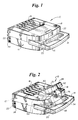
- a semi-automatic, automated external defibrillator (AED) 10 in accordance with the present invention is illustrated generally in Figures 1-3.
- defibrillator 10 includes a plastic case 12 with a carrying handle 14 on the top portion.
- a battery compartment (not visible) in the bottom portion of the defibrillator 10 is enclosed by a semi-transparent battery cover 16.
- An illuminatable rescue switch 18, visual maintenance indicator 20, data communication port 22 and charging port 24 are located on the outside of case 12 for easy access by an operator.
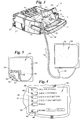
- Case 12 also includes an electrode compartment 26 between handle 14 and battery cover 16.
- the electrode compartment 26 is enclosed by lid 28 which is mounted to the case 12 by hinges (not visible).
- a friction-type releasable latch including pins 30 holds lid 28 closed when defibrillator 10 is not in use.
- the finger-receiving recess 31 in the lid 28 is grasped to open the lid and access the electrode compartment 26.
- An electrode connector 32, speaker 34 and diagnostic display panel 36 are located on case 12 within the electrode compartment 26.
- diagnostic display panel 36 includes visual "Call for Service” indicator light 38, "Check Electrode” indicator light 40, “Check 9 Volt Battery” indicator light 42, “Check 12 Volt Battery” indicator light 44 and “Power” indicator light 46.
- Resume switch 48 and resume indicator light 49 are also located on diagnostic panel 36.
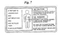
- An instruction and safety label such as that shown in Figure 7 is located on the inside surface of electrode compartment lid 28.
- Electrodes 50 each include a flexible polymer backing layer 52 and a patient-engaging layer 54 of conductive adhesive which overlays the backing layer.
- a current-dispersing flexible conductive sheet (not visible) is located between the backing layer 52 and patient-engaging layer 54.
- Insulated lead wires 56 extend from each electrode 50, and have a first end connected to the conductive sheet and a second end connected to connector 58.
- Connector 58 is configured to releasably mate with the electrode connector 32 in electrode compartment 26.
- Electrodes 50 are sealed within a polymer or polymer-metal laminate package 60 such as that shown in Figure 2.
- Lead wires 56 and connector 58 extend from package 60.
- the layers 54 of electrodes 50 are affixed in a face-to-face orientation to opposite sides of a release liner 61 within package 60.
- the release liner 61 is perforated with a number of apertures, so the electrodes 50 are electrically coupled to one another within the package 60.
- a relatively low resistance electrical circuit is thereby established between the ends of the lead wires 56 at connector 58.
- electrode package 60 is positioned within electrode compartment 26, and connector 58 plugged into the connector 32 in the compartment, to maintain defibrillator 10 in a ready-to-use state.
- Packaged electrodes 50 having the above-described characteristics are disclosed in the Gilman et al. U.S. Patent 5,402,884, and are commercially available from Survivalink of Minnetonka, Minnesota.
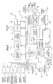
- FIG. 5 is a block diagram of the electrical system 70 of defibrillator 10.
- the overall operation of defibrillator 10 is controlled by a digital microprocessor-based control system 72 which includes a processor 74 interfaced to program memory 76, data memory 77, event memory 78 and real time clock 79.
- the operating program executed by processor 74 is stored in program memory 76.
- Data memory 77 is used by processor 74 as a scratch pad memory during the execution of the operating program.
- Electrical power is provided by a rechargeable twelve volt lead-acid cartridge battery 80 and a nine volt battery 82 which are removably positioned within the battery compartment and connected to power generation circuit 84.
- power generation circuit 84 During normal operation, power generation circuit 84 generates regulated ⁇ 5V, 3.3V and 12V (actually about 13.3V) supplies with the power provided by the twelve volt battery 80.
- Nine volt battery 82 functions as a back-up battery to power components of electrical system 70 during the execution of self-tests and to activate maintenance indicators and alarms (as described below) if the twelve volt battery 80 is low on charge.
- power generation circuit 84 includes voltage level sensing circuits which are coupled to processor 74. The voltage level sensing circuits provide low battery level signals to processor 74 whenever the voltage levels of batteries 80 or 82 are less than predetermined values such as 12.3V and 8V, respectively.
- the ⁇ 5V supply is used to power the control system 72 and most other electrical components of electrical system 70.
- the 3.3V supply is coupled to nonvolatile event memory 78 in which, as is described in greater detail below, data representative of the patient's cardiac rhythm and the rescue mode operation of defibrillator 10 are stored.
- a high voltage generation circuit 86 is connected to receive the 12V supply.
- Charging port 24 is coupled to power generation circuit 84, enabling twelve volt battery 80 to be connected to a twelve volt vehicle battery (not shown) or a 120VAC charger (also not shown) and recharged while mounted within the defibrillator 12. Alternatively battery 80 can be removed from defibrillator 10 and charged in a stand-alone charger (not shown).
- Defibrillator 10 cannot be operated when a charger is connected to charge port 24.
- Circuitry (not separately shown) within power generation circuit 84 senses the interconnection of port 24 to a charger, and provides a charger connected signal to processor 74 when a connected charger is sensed.
- Power generation circuit 84 is also connected to power control circuit 88 and processor 74.
- Power control circuit 88 is connected to lid switch 90, watch dog timer 92, real time clock 79 and processor 74.
- Lid switch 90 is a magnetic reed relay switch in one embodiment, and provides signals to processor 74 indicating whether lid 28 is open or closed.
- Data communication port 22 is coupled to processor 74 for two-way serial data transfer using an RS-232 protocol.
- Rescue switch 18, maintenance indicator 20, rescue switch light 19, resume switch 48, indicator lights 38, 40, 42, 44, 46 and 49 of diagnostic display panel 36, voice circuit 94 and piezoelectric audible alarm 96 are also connected to processor 74.
- Voice circuit 94 is connected to the speaker 34. In response to voice prompt control signals from processor 74, circuit 94 and speaker 34 generate the audible voice prompts described below.
- High voltage generation circuit 86 is also connected to and controlled by processor 74. Circuits such as 86 are generally known, and disclosed, for example, in the commonly assigned Persson et al. U.S. Patent 5,405,361, which is hereby incorporated by reference. In response to charge control signals provided by the processor 74, high voltage generation circuit 86 is operated in a charge mode during which one set of semiconductor switches (not separately shown) cause a plurality of capacitors (also not shown), to be charged in parallel to the 12V potential supplied by power generation circuit 84.
- high voltage generation circuit 86 is operated in a discharge mode during which the capacitors are discharged in series by another set of semiconductor switches (not separately shown) to produce the high voltage defibrillation pulses.
- the defibrillation pulses are applied to the patient through electrode connector 32 which is connected to the high voltage generation circuit 86.
- processor 74 causes high voltage generation circuit 86 to be discharged through an internal resistive load 98 rather than connector 32.
- Impedance measuring circuit 100 is connected to electrode connector 32 and real time clock 79, and is interfaced to processor 74 through analog-to-digital (A/D) converter 102.
- the impedance measuring circuit 100 receives a clock signal having a predetermined magnitude from clock 79, and applies the signal to electrodes 50 through connector 32.
- the magnitude of the clock signal received back from the electrodes 50 through connector 32 is monitored by impedance measuring circuit 100.
- An impedance signal representative of the impedance present across electrode connector 32 is then generated by circuit 100 as a function of the ratio of the magnitudes of the applied and received clock signals (i.e., the attenuation of the applied signal).
- a relatively low resistance e.g., less than about ten ohms
- a relatively high resistance e.g., greater than about one hundred ohms
- the resistance across connector 32 will be between about fifty and eighty ohms when fresh electrodes 50 are properly positioned on the patient with good electrical contacts.
- the impedance signal representative of the impedance measured by circuit 100 is digitized by A/D converter 102 and provided to processor 74.
- Defibrillator 10 also includes electrocardiogram (EKG) filter and amplifier 104 which is connected between electrode connector 32 and A/D converter 102.
- EKG electrocardiogram
- the EKG or cardiac rhythm of the patient is processed by filter and amplifier 104 in a conventional manner, and digitized by A/D converter 102 before being coupled to processor 74.
- the rescue mode operation of defibrillator 10 is initiated when an operator opens lid 28 to access the electrode package 60.
- the opening of the lid 28 is detected by lid switch 90, which effectively functions as an on/off switch.
- power control circuit 88 activates power generation circuit 84 and initiates rescue mode operation of processor 74.
- Processor 74 then begins its rescue mode operation by switching maintenance indicator 20 to a maintenance required state (e.g., a yellow visual display in one embodiment), flashing rescue switch light 19 and the indicator lights on diagnostic display panel 36, and performing a lid opened self-test.
- Processor 74 also initiates the generation of an audible voice prompt "To attempt a rescue, disconnect charger.” if a charger is connected to charge port 24 when lid 28 is opened.
- processor 74 checks: 1) the charge state of batteries 80 and 82, 2) the interconnection and operability of electrodes 50, 3) the state of event memory 78, 4) the functionality of real time clock 79, and 5) the functionality of A/D converter 102.
- the charge states of batteries 80 and 82 are checked by monitoring the voltage level signals provided by power generation circuit 84. If batteries 80 and/or 82 are determined to have a low charge, lights 44 and/or 42, respectively, on diagnostic display panel 36 are illuminated by processor 74.
- the interconnection and operability of the electrodes 50 is checked by monitoring the impedance signals provided by impedance measuring circuit 100.
- processor 74 will illuminate the indicator light 40 on diagnostic display panel 36.
- data representative of the operation of defibrillator 10 during a rescue and the patient's cardiac rhythm are stored in event memory 78. The data can be subsequently retrieved from event memory 78 through communications port 22, and the memory cleared.
- processor 74 accesses the event memory 78 to determine whether data from a previous rescue is still stored in the memory. If so, processor 74 causes light 49 on diagnostic panel 36 to be illuminated, and initiates the generation of a "Press resume button to clear memory and continue.” voice prompt.
- processor 74 clears event memory 78 and proceeds with its rescue mode operation.
- the functionality of real time clock 79 and A/D converter 102 are checked by monitoring the outputs of these circuit elements for expected signals. Diagnostic display panel light 38 is illuminated by processor 74 if faults are identified in either of clock 79 or converter 102.
- processor 74 switches maintenance indicator 20 to an operational state (e.g., a black color in one embodiment), and initiates the generation of an audible "Place electrodes.” voice prompt.
- an operational state e.g., a black color in one embodiment
- processor 74 monitors the impedance signals received through A/D converter 102 to determine whether the impedance across the electrodes indicates that they have been properly positioned on the patient. If the correct impedance is not measured, processor 74 initiates the generation of a "Check electrodes.” voice prompt.
- processor 74 After detecting an impedance indicating the proper placement of electrodes 50, and without further action by the operator (i.e., automatically), processor 74 begins a first analyze sequence by initiating the generation of a "Do not touch patient. Analyzing rhythm.” voice prompt, and analyzing the patient's cardiac rhythm. In one embodiment, processor 74 collects and analyzes a nine second segment of the patient's cardiac rhythm.
- the cardiac rhythm analysis program executed by processor 74 is stored in program memory 76. Algorithms of the type implemented by the rhythm analysis program are generally known and disclosed, for example, in the W. A. Tacker Jr. book Defibrillation of the Heart, 1994 .
- processor 74 determines that the patient has a nonshockable cardiac rhythm that is not susceptible to treatment by defibrillation pulses (e.g., no pulse rather than a fibrillating rhythm), it initiates the generation of a "Check pulse. If no pulse, give CPR.” voice prompt. One minute after this voice prompt, processor 74 repeats the initiation of the "Do not touch patient. Analyzing rhythm.” voice prompt and the associated cardiac rhythm analysis.
- processor 74 When a shockable cardiac rhythm is detected, processor 74 begins a first charge sequence by initiating the generation of a "Charging.” voice prompt, and causes high voltage generation circuit 86 to operate in the charge mode. When the high voltage generation circuit 86 is charged, processor 74 begins a first shock sequence by initiating the generation of a "Stand clear. Push flashing button to rescue.” voice prompt, and the flashing illumination of rescue switch light 19. The operator actuation of rescue switch 18 will then cause processor 74 to operate high voltage generation circuit 86 in the discharge mode, and results in the application of a defibrillation pulse to the patient to complete the first series of analyze/charge/shock sequences. In one embodiment, the first defibrillation pulse delivered by defibrillator 10 has an energy content of about two hundred joules.
- processor 74 times out a short pause of about five seconds to allow the heart to reestablish its cardiac rhythm before beginning a second series of analyze/charge/shock sequences.
- the second series of analyze/charge/shock sequences is identical to the first series described above, except the energy content of the defibrillation pulse can be about two hundred joules or three hundred joules. If the second series of analyze/charge/shock sequences ends with the delivery of a defibrillation pulse, processor 74 again times out a short pause of about five second before beginning a third analyze/charge/shock sequence.
- the third series is also identical to the first series, but processor 74 controls the high voltage generation circuit 86 in such a manner as to cause the defibrillation pulse delivered upon the actuation of the rescue switch 18 to have an energy content of about three hundred and sixty joules.
- processor 74 Following the delivery of a defibrillation pulse at the end of the third series of analyze/charge/shock sequences, or after identifying a nonshockable cardiac rhythm, processor 74 initiates the generation of a "Check Pulse. If no pulse, give CPR.” voice prompt. Processor 74 then times a one minute CPR period to complete a first set of three series of analyze/charge/shock sequences. Rescue mode operation then continues with additional sets of three series of analyze/charge/shock sequences of the type described above (all with three hundred and sixty joule pulses). Processor 74 ends rescue mode operation of defibrillator 10 when a total of nine series of analyze/charge/shock sequences have been performed, or lid 28 is closed.
- processor 74 monitors the impedance present across connector 32 to determine whether electrodes 50 remain properly positioned on the patient. If the monitored impedance is out of range (e.g., too high if the electrodes have come off the patient, or too low if shorted), processor 74 initiates the generation of a "Check Electrodes.” voice prompt, and causes high voltage generation circuit 86 to discharge any charge that may be present through internal load 98. Rescue mode operation will resume when processor 74 determines that the electrodes have been properly repositioned on the patient.
- Processor 74 initiates and performs a lid closed self-test when lid 28 is closed following rescue mode operation of the defibrillator 10.
- the lid closed self-test processor 74 performs a comprehensive check of the status and functionality of defibrillator 10, including: 1) the state of event memory 78, 2) the functionality of real time clock 79, 3) the functionality of A/D converter 102, 4) the functionality of program memory 76, data memory 77 and event memory 78, 5) the charge state of batteries 80 and 82, and 6) the interconnection and operability of electrodes 50.
- the state of event memory 78, the state of batteries 80 and 82, the interconnection and operability of electrodes 50, and the functionality of clock 79 and A/D converter 102 are checked in a manner identical to that described above with reference to the lid opened self-test.
- Conventional memory test routines are implemented to check the functionality of program memory 76, data memory 77 and event memory 78.
- Light 38 on diagnostic display panel 36 is illuminated (when lid 28 is subsequently opened), and maintenance indicator 20 is switched to its maintenance required state by processor 74 if faults are identified during the lid closed self-test. No audible alarms are actuated if faults are identified in the charge state of batteries 80 or 82 or the interconnection or functionality of electrodes 50 during the lid closed self test.
- alarm 96 is actuated by processor 74 if other faults are identified during the lid opened self test.
- a daily self-test is initiated and performed by processor 74 at a predetermined time each day (i.e., every twenty-four hours).
- processor 74 performs all the component check operations described above that are performed during the lid opened and lid closed self-tests.
- processor 74 switches maintenance indicator 20 to its maintenance required state and activates alarm 96 if faults are identified during the daily self-test.
- Processor 74 also initiates and performs a weekly self-test at a predetermined time one day each week. During the weekly self-test processor 74 performs all the component check operations described above that are performed during the daily self-test. In addition, processor 74 causes high voltage generation circuit 86 to sequentially operate in its charge and discharge modes, with the charge being dumped to the internal load 98. While the high voltage generation circuit 86 is operating in the charge mode, processor 74 monitors the time required to charge the capacitors and the capacitor voltage. A fault is identified if either is out of nominal conditions. Maintenance indicator 20 and alarm 96 are actuated in the manner described above if any faults are identified during the weekly self-test.
- Watch dog timer 92 is set to time watch dog time-out periods of about thirty hours (i.e., a period greater than the twenty-four hour periods between daily self-tests), and is reset by processor 74 at the beginning of each daily self-test and each time lid 26 is opened.
- power control circuit 88 causes processor 74 to switch maintenance indicator 20 to the maintenance required state and to actuate alarm 96 to alert an operator to the fact that defibrillator 10 requires maintenance.
- Data representative of the operation of defibrillator 10 and the monitored cardiac rhythm of the patient are stored in event memory 78 during rescue mode operation.
- Stored data representative of the operation of defibrillator 10 includes the real time of the occurrence of each of the following events: 1) the placement of electrodes 50 on the patient, 2) the initiation of the cardiac rhythm analysis voice prompt, 3) the initiation of the charging voice prompt, 4) the completion of the charge mode operation of high voltage generation circuit 86 , and 5) the actuation of rescue switch 18.
- the actual time base of the patient's cardiac rhythm is also stored in memory 78.
- the stored data can be retrieved from event memory 78 through the use of a personal computer (PC) (not shown) interfaced to communications port 22.
- Real time clock 79 can also be set through the use of a PC interfaced to communications port 22.
- Defibrillator 10 offers considerable advantages.
- the device is relatively easy to use.
- the lid-actuated on-off switch, voice prompts, "one button" rescue operation and other aspects of the operator interface help enable high-quality defibrillation rescues.
- the wide range of self-tests and diagnostic displays enable operators to conveniently and accurately assess the operational status of the defibrillator.
Abstract
Description
- The present invention relates generally to automated external defibrillators. In particular, the present invention is an operator interface for an automated external defibrillator.
- Automated external defibrillators or AEDs are commonly used by police officers, paramedics and other first-responder emergency medical technicians to resuscitate cardiac arrest patients. Generally, to perform a rescue using an AED the medical technician will interconnect a pair of defibrillation electrodes to the defibrillator, position the electrodes on the patient's chest and operate the defibrillator through its operator interface. AED operator interfaces typically include a number of switches that must be actuated to turn the defibrillator on and to initiate the application of defibrillation pulses. Visual displays, audible indicators and voice prompts which indicate the operational status of the defibrillator and instruct the technician on the use of the device are also sometimes included in AED operator interfaces.
- AEDs are used in high-stress emergency situations. Time is also of the essence since studies have also shown that the chances of successfully resuscitating a patient decrease approximately ten percent per minute following cardiac arrest. There is, therefore, a continuing need for improved AEDs and associated operator interfaces that are relatively easy-to-use and capable of providing high-quality defibrillation rescues.
- The present invention is defined in the accompanying independent claim. Preferred features are recited in the dependent claims.
- The present invention is an improved automated external defibrillator (AED). One embodiment of the defibrillator includes a case having an electrode compartment configured to hold a pair of defibrillator electrodes, and an openable lid for enclosing the compartment. A lid switch on the case senses when the lid is opened. Electrode terminals in the electrode compartment are configured for electrical interconnection to the defibrillator electrodes. A battery compartment and battery terminals in the case are configured for holding and electrical interconnection to one or more batteries. A high voltage circuit for generating defibrillation pulses is coupled to the battery and electrode terminals. An operator-actuated rescue switch and a rescue indicator are also located on the case. A digital control system is coupled to the lid switch, electrode terminals, high voltage circuit, rescue switch and rescue indicator. The digital control system includes rescue mode initiating means, rhythm analyzing means, rescue indicator actuating means and pulse initiating means. The rescue mode initiating means initiates rescue mode operation of the defibrillator when the lid is opened. Signals present on the electrode terminals are analyzed by the rhythm analyzing means to identify a shockable cardiac rhythm. When a shockable rhythm is identified, the rescue indicator is activated by the rescue indicator actuating means. The pulse initiating means actuates the high voltage circuit and causes the generation of defibrillation pulses when a shockable rhythm is identified and the rescue switch is actuated. The rescue indicator can include both an audible voice prompt and a visual display.
- Another embodiment of the invention is configured for use with a pair of packaged electrodes electrically connected to one another within the package, and further includes a place electrodes indicator, a check electrodes indicator and an impedance measuring circuit. The place electrodes indicator includes an audible voice prompt. The check electrodes indicator includes both an audible voice prompt and a visual display. The impedance measuring circuit is coupled between the electrode terminals and the digital control system, and measures the impedance between the electrode terminals. The digital control system of this embodiment includes place electrodes indicator actuating means, electrode connection checking means and electrode application checking means. The place electrodes indicator actuating means actuates the place electrodes indicator after the lid is opened and before analyzing signals present on the electrode terminals. The electrode connection checking means identifies improper electrode connections to the electrode terminals as a function of the measured impedance between the electrode terminals, and actuates the check electrode indicator when improper electrode connections are identified. The electrode application checking means identifies improper electrode placement on a patient as a function of the measured impedance between the electrode terminals, and actuates the check electrodes indicator when improper electrode placement is identified.
- Yet another embodiment of the defibrillator includes an audible voice prompt analyzing rhythm indicator, an audible voice prompt charging indicator and an audible voice prompt nonshockable rhythm indicator. The digital control system of this embodiment further includes rhythm indicator actuating means, charging indicator actuating means and nonshockable rhythm indicator actuating means. The rhythm indicator actuating means actuates the analyzing rhythm indicator when analyzing signals on the electrode terminals to identify a shockable rhythm. The charging indicator actuating means actuates the charging indicator when the high voltage circuit is charging and before the rescue indicator is actuated. The nonshockable rhythm indicator actuating means actuates the nonshockable rhythm indicator when a nonshockable rhythm is identified by the rhythm analyzing means.
- The invention can be put into practice in various ways, some of which will now be described with reference to the accompanying drawings, in which:
- Figure 1 is a perspective view of an automated external defibrillator (AED) in accordance with the present invention, with the electrode compartment lid closed
- Figure 2 is a perspective view of the AED shown in Figure 1, with the electrode compartment lid opened and the packaged electrodes positioned therein
- Figure 3 is a perspective view of the AED shown in Figure 2, with the electrodes removed from the electrode compartment and the package
- Figure 4 is a detailed view of the diagnostic display panel in the electrode compartment;
- Figure 5 is a detailed view of the unpackaged electrodes positioned on the release liner;
- Figure 6 is a block diagram of the electrical system of the AED shown in Figure 1; and
- Figure 7 is an illustration of the instruction and safety label on the inside surface of the electrode compartment lid.
- A semi-automatic, automated external defibrillator (AED) 10 in accordance with the present invention is illustrated generally in Figures 1-3. As shown,
defibrillator 10 includes aplastic case 12 with acarrying handle 14 on the top portion. A battery compartment (not visible) in the bottom portion of thedefibrillator 10 is enclosed by asemi-transparent battery cover 16. Anilluminatable rescue switch 18,visual maintenance indicator 20,data communication port 22 andcharging port 24 are located on the outside ofcase 12 for easy access by an operator. -
Case 12 also includes anelectrode compartment 26 betweenhandle 14 andbattery cover 16. Theelectrode compartment 26 is enclosed bylid 28 which is mounted to thecase 12 by hinges (not visible). A friction-type releasablelatch including pins 30 holdslid 28 closed whendefibrillator 10 is not in use. The finger-receiving recess 31 in thelid 28 is grasped to open the lid and access theelectrode compartment 26. Anelectrode connector 32,speaker 34 anddiagnostic display panel 36 are located oncase 12 within theelectrode compartment 26. As shown in Figure 4,diagnostic display panel 36 includes visual "Call for Service"indicator light 38, "Check Electrode"indicator light 40, "Check 9 Volt Battery"indicator light 42, "Check 12 Volt Battery"indicator light 44 and "Power"indicator light 46.Resume switch 48 andresume indicator light 49 are also located ondiagnostic panel 36. An instruction and safety label such as that shown in Figure 7 is located on the inside surface ofelectrode compartment lid 28. - A pair of
defibrillator electrodes 50 which can be used withdefibrillator 10 are shown in Figures 3 and 5.Electrodes 50 each include a flexiblepolymer backing layer 52 and a patient-engaging layer 54 of conductive adhesive which overlays the backing layer. A current-dispersing flexible conductive sheet (not visible) is located between thebacking layer 52 and patient-engaging layer 54.Insulated lead wires 56 extend from eachelectrode 50, and have a first end connected to the conductive sheet and a second end connected toconnector 58.Connector 58 is configured to releasably mate with theelectrode connector 32 inelectrode compartment 26.Electrodes 50 are sealed within a polymer or polymer-metal laminate package 60 such as that shown in Figure 2.Lead wires 56 andconnector 58 extend frompackage 60. Thelayers 54 ofelectrodes 50 are affixed in a face-to-face orientation to opposite sides of arelease liner 61 withinpackage 60. Therelease liner 61 is perforated with a number of apertures, so theelectrodes 50 are electrically coupled to one another within thepackage 60. A relatively low resistance electrical circuit is thereby established between the ends of thelead wires 56 atconnector 58. As shown in Figure 2,electrode package 60 is positioned withinelectrode compartment 26, andconnector 58 plugged into theconnector 32 in the compartment, to maintaindefibrillator 10 in a ready-to-use state.Packaged electrodes 50 having the above-described characteristics are disclosed in the Gilman et al. U.S. Patent 5,402,884, and are commercially available from Survivalink of Minnetonka, Minnesota. - Figure 5 is a block diagram of the
electrical system 70 ofdefibrillator 10. The overall operation ofdefibrillator 10 is controlled by a digital microprocessor-basedcontrol system 72 which includes a processor 74 interfaced toprogram memory 76,data memory 77,event memory 78 andreal time clock 79. The operating program executed by processor 74 is stored inprogram memory 76.Data memory 77 is used by processor 74 as a scratch pad memory during the execution of the operating program. Electrical power is provided by a rechargeable twelve volt lead-acid cartridge battery 80 and a ninevolt battery 82 which are removably positioned within the battery compartment and connected topower generation circuit 84. During normal operation,power generation circuit 84 generates regulated ±5V, 3.3V and 12V (actually about 13.3V) supplies with the power provided by the twelvevolt battery 80. Ninevolt battery 82 functions as a back-up battery to power components ofelectrical system 70 during the execution of self-tests and to activate maintenance indicators and alarms (as described below) if the twelvevolt battery 80 is low on charge. Although not separately shown in Figure 5,power generation circuit 84 includes voltage level sensing circuits which are coupled to processor 74. The voltage level sensing circuits provide low battery level signals to processor 74 whenever the voltage levels ofbatteries - The ±5V supply is used to power the
control system 72 and most other electrical components ofelectrical system 70. The 3.3V supply is coupled tononvolatile event memory 78 in which, as is described in greater detail below, data representative of the patient's cardiac rhythm and the rescue mode operation ofdefibrillator 10 are stored. A highvoltage generation circuit 86 is connected to receive the 12V supply. Chargingport 24 is coupled topower generation circuit 84, enabling twelvevolt battery 80 to be connected to a twelve volt vehicle battery (not shown) or a 120VAC charger (also not shown) and recharged while mounted within thedefibrillator 12. Alternativelybattery 80 can be removed fromdefibrillator 10 and charged in a stand-alone charger (not shown).Defibrillator 10 cannot be operated when a charger is connected to chargeport 24. Circuitry (not separately shown) withinpower generation circuit 84 senses the interconnection ofport 24 to a charger, and provides a charger connected signal to processor 74 when a connected charger is sensed. -
Power generation circuit 84 is also connected topower control circuit 88 and processor 74.Power control circuit 88 is connected tolid switch 90,watch dog timer 92,real time clock 79 and processor 74.Lid switch 90 is a magnetic reed relay switch in one embodiment, and provides signals to processor 74 indicating whetherlid 28 is open or closed.Data communication port 22 is coupled to processor 74 for two-way serial data transfer using an RS-232 protocol.Rescue switch 18,maintenance indicator 20, rescue switch light 19, resumeswitch 48, indicator lights 38, 40, 42, 44, 46 and 49 ofdiagnostic display panel 36,voice circuit 94 and piezoelectricaudible alarm 96 are also connected to processor 74.Voice circuit 94 is connected to thespeaker 34. In response to voice prompt control signals from processor 74,circuit 94 andspeaker 34 generate the audible voice prompts described below. - High
voltage generation circuit 86 is also connected to and controlled by processor 74. Circuits such as 86 are generally known, and disclosed, for example, in the commonly assigned Persson et al. U.S. Patent 5,405,361, which is hereby incorporated by reference. In response to charge control signals provided by the processor 74, highvoltage generation circuit 86 is operated in a charge mode during which one set of semiconductor switches (not separately shown) cause a plurality of capacitors (also not shown), to be charged in parallel to the 12V potential supplied bypower generation circuit 84. Once charged, and in response to discharge control signals provided by processor 74, highvoltage generation circuit 86 is operated in a discharge mode during which the capacitors are discharged in series by another set of semiconductor switches (not separately shown) to produce the high voltage defibrillation pulses. The defibrillation pulses are applied to the patient throughelectrode connector 32 which is connected to the highvoltage generation circuit 86. Under certain circumstances described below, processor 74 causes highvoltage generation circuit 86 to be discharged through an internalresistive load 98 rather thanconnector 32. -
Impedance measuring circuit 100 is connected toelectrode connector 32 andreal time clock 79, and is interfaced to processor 74 through analog-to-digital (A/D)converter 102. Theimpedance measuring circuit 100 receives a clock signal having a predetermined magnitude fromclock 79, and applies the signal toelectrodes 50 throughconnector 32. The magnitude of the clock signal received back from theelectrodes 50 throughconnector 32 is monitored byimpedance measuring circuit 100. An impedance signal representative of the impedance present acrosselectrode connector 32 is then generated bycircuit 100 as a function of the ratio of the magnitudes of the applied and received clock signals (i.e., the attenuation of the applied signal). For example, if theelectrodes 50 withinpackage 60 are operational and theconnector 58 is properly connected toconnector 32 ondefibrillator 10, a relatively low resistance (e.g., less than about ten ohms) should be present across theconnector 32. If the conductive adhesive on theelectrodes 50 is dried out, theconnector 58 is not properly connected toconnector 32, or the electrodes are not properly positioned on the patient, a relatively high resistance (e.g, greater than about one hundred ohms) will be present across theconnector 32. The resistance acrossconnector 32 will be between about fifty and eighty ohms whenfresh electrodes 50 are properly positioned on the patient with good electrical contacts. The impedance signal representative of the impedance measured bycircuit 100 is digitized by A/D converter 102 and provided to processor 74. -
Defibrillator 10 also includes electrocardiogram (EKG) filter andamplifier 104 which is connected betweenelectrode connector 32 and A/D converter 102. The EKG or cardiac rhythm of the patient is processed by filter andamplifier 104 in a conventional manner, and digitized by A/D converter 102 before being coupled to processor 74. - The rescue mode operation of
defibrillator 10 is initiated when an operator openslid 28 to access theelectrode package 60. The opening of thelid 28 is detected bylid switch 90, which effectively functions as an on/off switch. In response to this action,power control circuit 88 activatespower generation circuit 84 and initiates rescue mode operation of processor 74. Processor 74 then begins its rescue mode operation by switchingmaintenance indicator 20 to a maintenance required state (e.g., a yellow visual display in one embodiment), flashing rescue switch light 19 and the indicator lights ondiagnostic display panel 36, and performing a lid opened self-test. Processor 74 also initiates the generation of an audible voice prompt "To attempt a rescue, disconnect charger." if a charger is connected to chargeport 24 whenlid 28 is opened. - During the lid opened self-test, processor 74 checks: 1) the charge state of
batteries electrodes 50, 3) the state ofevent memory 78, 4) the functionality ofreal time clock 79, and 5) the functionality of A/D converter 102. The charge states ofbatteries power generation circuit 84. Ifbatteries 80 and/or 82 are determined to have a low charge, lights 44 and/or 42, respectively, ondiagnostic display panel 36 are illuminated by processor 74. The interconnection and operability of theelectrodes 50 is checked by monitoring the impedance signals provided byimpedance measuring circuit 100. If thepackage 60 ofelectrodes 50 is missing or unplugged fromconnector 32, or if the electrodes are damaged (e.g., dried out), processor 74 will illuminate theindicator light 40 ondiagnostic display panel 36. As described in greater detail below, data representative of the operation ofdefibrillator 10 during a rescue and the patient's cardiac rhythm are stored inevent memory 78. The data can be subsequently retrieved fromevent memory 78 throughcommunications port 22, and the memory cleared. During the lid opened self-test, processor 74 accesses theevent memory 78 to determine whether data from a previous rescue is still stored in the memory. If so, processor 74 causes light 49 ondiagnostic panel 36 to be illuminated, and initiates the generation of a "Press resume button to clear memory and continue." voice prompt. Ifresume switch 18 is pressed by the operator following the activation of these indicators, processor 74 clearsevent memory 78 and proceeds with its rescue mode operation. The functionality ofreal time clock 79 and A/D converter 102 are checked by monitoring the outputs of these circuit elements for expected signals. Diagnosticdisplay panel light 38 is illuminated by processor 74 if faults are identified in either ofclock 79 orconverter 102. - If the lid opened self-test is successfully completed, processor 74
switches maintenance indicator 20 to an operational state (e.g., a black color in one embodiment), and initiates the generation of an audible "Place electrodes." voice prompt. In response to this voice prompt, and following the instructions on the inside oflid 28, the operator should removeelectrode package 60 fromcompartment 26, open the package,peel electrodes 50 from therelease liner 61 and place the electrodes on the patient's chest. While this action is being performed, processor 74 monitors the impedance signals received through A/D converter 102 to determine whether the impedance across the electrodes indicates that they have been properly positioned on the patient. If the correct impedance is not measured, processor 74 initiates the generation of a "Check electrodes." voice prompt. - After detecting an impedance indicating the proper placement of
electrodes 50, and without further action by the operator (i.e., automatically), processor 74 begins a first analyze sequence by initiating the generation of a "Do not touch patient. Analyzing rhythm." voice prompt, and analyzing the patient's cardiac rhythm. In one embodiment, processor 74 collects and analyzes a nine second segment of the patient's cardiac rhythm. The cardiac rhythm analysis program executed by processor 74 is stored inprogram memory 76. Algorithms of the type implemented by the rhythm analysis program are generally known and disclosed, for example, in the W. A. Tacker Jr. book Defibrillation of the Heart, 1994. If the processor 74 determines that the patient has a nonshockable cardiac rhythm that is not susceptible to treatment by defibrillation pulses (e.g., no pulse rather than a fibrillating rhythm), it initiates the generation of a "Check pulse. If no pulse, give CPR." voice prompt. One minute after this voice prompt, processor 74 repeats the initiation of the "Do not touch patient. Analyzing rhythm." voice prompt and the associated cardiac rhythm analysis. - When a shockable cardiac rhythm is detected, processor 74 begins a first charge sequence by initiating the generation of a "Charging." voice prompt, and causes high
voltage generation circuit 86 to operate in the charge mode. When the highvoltage generation circuit 86 is charged, processor 74 begins a first shock sequence by initiating the generation of a "Stand clear. Push flashing button to rescue." voice prompt, and the flashing illumination of rescue switch light 19. The operator actuation ofrescue switch 18 will then cause processor 74 to operate highvoltage generation circuit 86 in the discharge mode, and results in the application of a defibrillation pulse to the patient to complete the first series of analyze/charge/shock sequences. In one embodiment, the first defibrillation pulse delivered bydefibrillator 10 has an energy content of about two hundred joules. - Following the first series of analyze/charge/shock sequences, processor 74 times out a short pause of about five seconds to allow the heart to reestablish its cardiac rhythm before beginning a second series of analyze/charge/shock sequences. The second series of analyze/charge/shock sequences is identical to the first series described above, except the energy content of the defibrillation pulse can be about two hundred joules or three hundred joules. If the second series of analyze/charge/shock sequences ends with the delivery of a defibrillation pulse, processor 74 again times out a short pause of about five second before beginning a third analyze/charge/shock sequence. The third series is also identical to the first series, but processor 74 controls the high
voltage generation circuit 86 in such a manner as to cause the defibrillation pulse delivered upon the actuation of therescue switch 18 to have an energy content of about three hundred and sixty joules. - Following the delivery of a defibrillation pulse at the end of the third series of analyze/charge/shock sequences, or after identifying a nonshockable cardiac rhythm, processor 74 initiates the generation of a "Check Pulse. If no pulse, give CPR." voice prompt. Processor 74 then times a one minute CPR period to complete a first set of three series of analyze/charge/shock sequences. Rescue mode operation then continues with additional sets of three series of analyze/charge/shock sequences of the type described above (all with three hundred and sixty joule pulses). Processor 74 ends rescue mode operation of
defibrillator 10 when a total of nine series of analyze/charge/shock sequences have been performed, orlid 28 is closed. - Throughout the analyze, charge and shock sequences, processor 74 monitors the impedance present across
connector 32 to determine whetherelectrodes 50 remain properly positioned on the patient. If the monitored impedance is out of range (e.g., too high if the electrodes have come off the patient, or too low if shorted), processor 74 initiates the generation of a "Check Electrodes." voice prompt, and causes highvoltage generation circuit 86 to discharge any charge that may be present throughinternal load 98. Rescue mode operation will resume when processor 74 determines that the electrodes have been properly repositioned on the patient. - Processor 74 initiates and performs a lid closed self-test when
lid 28 is closed following rescue mode operation of thedefibrillator 10. During the lid closed self-test processor 74 performs a comprehensive check of the status and functionality ofdefibrillator 10, including: 1) the state ofevent memory 78, 2) the functionality ofreal time clock 79, 3) the functionality of A/D converter 102, 4) the functionality ofprogram memory 76,data memory 77 andevent memory 78, 5) the charge state ofbatteries electrodes 50. The state ofevent memory 78, the state ofbatteries electrodes 50, and the functionality ofclock 79 and A/D converter 102 are checked in a manner identical to that described above with reference to the lid opened self-test. Conventional memory test routines are implemented to check the functionality ofprogram memory 76,data memory 77 andevent memory 78.Light 38 ondiagnostic display panel 36 is illuminated (whenlid 28 is subsequently opened), andmaintenance indicator 20 is switched to its maintenance required state by processor 74 if faults are identified during the lid closed self-test. No audible alarms are actuated if faults are identified in the charge state ofbatteries electrodes 50 during the lid closed self test. However,alarm 96 is actuated by processor 74 if other faults are identified during the lid opened self test. - A daily self-test is initiated and performed by processor 74 at a predetermined time each day (i.e., every twenty-four hours). During the daily self-test processor 74 performs all the component check operations described above that are performed during the lid opened and lid closed self-tests. In addition to illuminating the appropriate lights on
diagnostic display panel 36, processor 74switches maintenance indicator 20 to its maintenance required state and activatesalarm 96 if faults are identified during the daily self-test. - Processor 74 also initiates and performs a weekly self-test at a predetermined time one day each week. During the weekly self-test processor 74 performs all the component check operations described above that are performed during the daily self-test. In addition, processor 74 causes high
voltage generation circuit 86 to sequentially operate in its charge and discharge modes, with the charge being dumped to theinternal load 98. While the highvoltage generation circuit 86 is operating in the charge mode, processor 74 monitors the time required to charge the capacitors and the capacitor voltage. A fault is identified if either is out of nominal conditions.Maintenance indicator 20 andalarm 96 are actuated in the manner described above if any faults are identified during the weekly self-test. - Watch
dog timer 92 is set to time watch dog time-out periods of about thirty hours (i.e., a period greater than the twenty-four hour periods between daily self-tests), and is reset by processor 74 at the beginning of each daily self-test and eachtime lid 26 is opened. In theevent control system 70 malfunctions and watchdog timer 92 times out,power control circuit 88 causes processor 74 to switchmaintenance indicator 20 to the maintenance required state and to actuatealarm 96 to alert an operator to the fact thatdefibrillator 10 requires maintenance. - Data representative of the operation of
defibrillator 10 and the monitored cardiac rhythm of the patient are stored inevent memory 78 during rescue mode operation. Stored data representative of the operation ofdefibrillator 10 includes the real time of the occurrence of each of the following events: 1) the placement ofelectrodes 50 on the patient, 2) the initiation of the cardiac rhythm analysis voice prompt, 3) the initiation of the charging voice prompt, 4) the completion of the charge mode operation of highvoltage generation circuit 86 , and 5) the actuation ofrescue switch 18. The actual time base of the patient's cardiac rhythm is also stored inmemory 78. Following a rescue, the stored data can be retrieved fromevent memory 78 through the use of a personal computer (PC) (not shown) interfaced tocommunications port 22.Real time clock 79 can also be set through the use of a PC interfaced tocommunications port 22. -
Defibrillator 10 offers considerable advantages. In particular, the device is relatively easy to use. The lid-actuated on-off switch, voice prompts, "one button" rescue operation and other aspects of the operator interface help enable high-quality defibrillation rescues. The wide range of self-tests and diagnostic displays enable operators to conveniently and accurately assess the operational status of the defibrillator. - Although the present invention has been described with reference to preferred embodiments, those skilled in the art will recognized that changes can be made in form and detail without departing from the scope of the invention.
Claims (15)
- An automated external defibrillator, comprising:a case including an electrode compartment and an openable lid for closing the compartment, the compartment configured to hold a pair of defibrillator electrodes;electrode terminals in the electrode compartment, the electrode terminals configured for electrical interconnection to defibrillator electrodes;a battery compartment and battery terminals in the case, the battery compartment and terminals configured for holding and electrical interconnection to one or more batteries;a high voltage circuit coupled to the battery terminals and the electrode terminals, for generating defibrillation pulses and applying the pulses to the electrode terminals;an operator-actuated rescue switch on the case;a rescue indicator on the case; anda digital control system coupled to the lid switch, electrode terminals, high voltage circuit, rescue switch and rescue indicator, including:rescue mode initiating means for initiating rescue operation of the defibrillator when the lid is opened;rhythm analyzing means for analyzing signals present on the electrode terminals to identify a shockable cardiac rhythm;rescue indicator actuating means for activating the rescue indicator when a shockable rhythm is identified; andpulse initiating means for actuating the high voltage circuit and causing the generation of defibrillation pulses when a shockable rhythm is identified and the rescue switch is actuated.
- The defibrillator of claim 1 further including an on/off switch.
- The defibrillator of claim 2 wherein the on/off switch includes a lid switch for sensing when the lid is open and wherein the rescue mode initiating means is responsive to the lid switch and initiates rescue mode operation of the defibrillator when the lid is open.
- The defibrillator of claim 1, 2 or 3, wherein the rescue indicator includes an audible voice prompt and/or a visual display.
- The defibrillator of claim 1, 2, 3 or 4,further including a place electrodes indicator; andthe digital control system further including place electrodes indicator actuating means for actuating the place electrodes indicator after the lid is opened and before analyzing signals present on the electrode terminals.
- The defibrillator of claim 5 further includingan impedance measuring circuit coupled between the electrode terminals and the digital control system, for measuring the impedance between the electrode terminals; anda check electrodes indicator;the digital control system further including electrode application checking means for identifying improper electrode placement on a patient as a function of the measured impedance between the electrode terminals, and for actuating the check electrodes indicator when improper electrode placement is identified.
- The defibrillator of claim 6
further including an internal load coupled to the high voltage circuit, the electrode application checking means being operable to the high voltage circuit to dissipate any charge to the internal load when an improper electrode placement is identified. - The defibrillator of claim 6configured for use with a pair of packaged electrodes electrically coupled to one another within the package; andthe digital control system further includes electrode connection checking means for identifying improper electrode connections to the electrode terminals as a function of the measured impedance between the electrode terminals, and actuates the check electrode indicator when improper electrode connections are identified.
- The defibrillator of claim 6,7 or 8, wherein the rhythm analyzing means automatically initiates the analysis of signals present on the electrode terminals when proper electrode placement is identified by the electrode checking means.
- The defibrillator of any of claims 1 to 7
configured for use with a pair of packaged electrodes electrically coupled to one another within the package. - The defibrillator of any of claims 1 to 10, wherein:the defibrillator further includes an analyzing rhythm indicator; andthe digital control system further includes rhythm indicator actuating means for actuating the analyzing rhythm indicator when analyzing signals on the electrode terminals to identify a shockable rhythm.
- The defibrillator of any of claims 1 to 11, wherein:the defibrillator further includes a charging indicator; andthe digital control system further includes charging indicator actuating means for actuating the charging indicator when the high voltage circuit is charging and before the rescue indicator is actuated.
- The defibrillator of any of claims 1 to 12, wherein:the defibrillator further includes a nonshockable rhythm indicator; andthe digital control system further includes nonshockable indicator actuating means for actuating the nonshockable rhythm indicator when an nonshockable rhythm is identified by the rhythm analyzing means.
- The defibrillator of any of claims 1 to 13, wherein:the defibrillator further includes a data communication port on the case coupled to the digital control system; andthe digital control system further includes:event storage means for storing rescue data representative of the rescue operation of the defibrillator and/or monitored cardiac rhythms; andrescue data transfer means for transferring the rescue data to the data communication port.
- The defibrillator of claim 14 wherein:the defibrillator further includes:a resume indicator coupled to the digital control system; andan operator-actuated resume button coupled to the digital control system; andthe digital control system further includes:resume indicator actuating means for actuating the resume indicator if rescue data is stored in the digital control system when the lid is opened; andmemory clearing means for clearing the rescue data from the digital control system when the resume button is actuated.
Applications Claiming Priority (2)
| Application Number | Priority Date | Filing Date | Title |
|---|---|---|---|
| US50999095A | 1995-08-01 | 1995-08-01 | |
| US509990 | 1995-08-01 |
Publications (3)
| Publication Number | Publication Date |
|---|---|
| EP0756878A2 true EP0756878A2 (en) | 1997-02-05 |
| EP0756878A3 EP0756878A3 (en) | 1998-05-13 |
| EP0756878B1 EP0756878B1 (en) | 2003-05-28 |
Family
ID=24028903
Family Applications (1)
| Application Number | Title | Priority Date | Filing Date |
|---|---|---|---|
| EP96305633A Expired - Lifetime EP0756878B1 (en) | 1995-08-01 | 1996-07-31 | Automated external defribillator |
Country Status (3)
| Country | Link |
|---|---|
| US (2) | US5645571B1 (en) |
| EP (1) | EP0756878B1 (en) |
| DE (1) | DE69628378T2 (en) |
Cited By (11)
| Publication number | Priority date | Publication date | Assignee | Title |
|---|---|---|---|---|
| WO1998026715A1 (en) * | 1996-12-16 | 1998-06-25 | Serif Ildan Metin | An apparatus which shows the place of the temporary pacemaker electrodes or similar conductors |
| WO1999059673A1 (en) * | 1998-05-21 | 1999-11-25 | Medtronic Physio-Control Manufacturing Corp. | Automatic detection and reporting of cardiac asystole |
| GB2341103A (en) * | 1998-09-02 | 2000-03-08 | Heartstream Inc | Defibrillator with reconfigurable heart analysis to match operator skill |
| WO2000030712A1 (en) * | 1998-11-20 | 2000-06-02 | Medtronic Physio-Control Manufacturing Corp. | Visual and aural user interface for an automated external defibrillator |
| EP1157717A1 (en) * | 2000-05-26 | 2001-11-28 | Laerdal Medical AS | System for measuring and analysing Cardio-Pulmonary Resuscitation (CPR) parameters for use with and by an external defibrillator (AED) |
| WO2003053519A3 (en) * | 2001-12-21 | 2003-11-27 | Koninkl Philips Electronics Nv | Defibrillator with automatic turn on, defibrillator storage case, and related system and method |
| WO2004037670A1 (en) * | 2002-10-23 | 2004-05-06 | Koninklijke Philips Electronics N.V. | Method and apparatus for facilitating opening a sealed medical electrode package |
| EP1419798A2 (en) * | 1995-08-08 | 2004-05-19 | Survivalink Corporation | Automated external defibrillator |
| AU781601B2 (en) * | 2000-05-08 | 2005-06-02 | Laerdal Medical As | External defibrillator |
| EP1637181A1 (en) * | 1995-08-08 | 2006-03-22 | Cardiac Science, Inc. | Automated external defibrillator |
| EP2116276A3 (en) * | 2000-06-12 | 2010-12-01 | Cardiac Science Corporation | A public access defibrillator |
Families Citing this family (180)
| Publication number | Priority date | Publication date | Assignee | Title |
|---|---|---|---|---|
| US5593426A (en) * | 1994-12-07 | 1997-01-14 | Heartstream, Inc. | Defibrillator system using multiple external defibrillators and a communications network |
| EP0956089A4 (en) * | 1996-05-10 | 2000-11-08 | Survivalink Corp | Defibrillator electrode circuitry |
| US5697955A (en) * | 1996-05-10 | 1997-12-16 | Survivalink Corporation | Defibrillator electrodes and date code detector circuit |
| US6148233A (en) * | 1997-03-07 | 2000-11-14 | Cardiac Science, Inc. | Defibrillation system having segmented electrodes |
| GB9704843D0 (en) * | 1997-03-08 | 1997-04-23 | Murphy Graham F | Apparatus |
| AU7107698A (en) * | 1997-04-08 | 1998-10-30 | Survivlink Corporation | Aami specification optimized truncated exponential waveform |
| US5955956A (en) * | 1997-04-08 | 1999-09-21 | Survivalink Corporation | Audible alarm system for an automated external defibrillator |
| US5899925A (en) * | 1997-08-07 | 1999-05-04 | Heartstream, Inc. | Method and apparatus for aperiodic self-testing of a defibrillator |
| US6090056A (en) * | 1997-08-27 | 2000-07-18 | Emergency Medical Systems, Inc. | Resuscitation and alert system |
| US6115638A (en) * | 1998-05-04 | 2000-09-05 | Survivalink Corporation | Medical electrode with conductive release liner |
| DE19827478A1 (en) * | 1998-06-19 | 2000-01-05 | Marquette Hellige Gmbh | Medical emergency device with built-in battery device |
| US6327497B1 (en) | 1998-09-11 | 2001-12-04 | Life Corporation | Portable emergency oxygen and automatic external defibrillator (AED) therapy system |
| USRE38533E1 (en) * | 1998-09-11 | 2004-06-15 | Life Corporation | Portable emergency oxygen and automatic external defibrillator (AED) therapy system |
| US6125299A (en) | 1998-10-29 | 2000-09-26 | Survivalink Corporation | AED with force sensor |
| US6422669B1 (en) * | 1998-11-09 | 2002-07-23 | Koninklijke Philips Electronics N.V. | Carrying case for defibrillator |
| NO310137B1 (en) * | 1998-12-11 | 2001-05-28 | Laerdal Medical As | System for measuring and analyzing CPR parameters for use with and by an external defibrillator |
| US6201992B1 (en) | 1999-04-01 | 2001-03-13 | Agilent Technologies, Inc. | Defibrillator interface capable of generating video images |
| US6405082B1 (en) * | 2000-01-24 | 2002-06-11 | Koninklijke Philips Electronics N.V. | Method and apparatus for distinguishing between therapy modes in a defibrillator |
| EP2308557A3 (en) * | 2000-02-04 | 2011-08-24 | Zoll Medical Corporation | Integrated resuscitation |
| US20050131465A1 (en) * | 2000-02-04 | 2005-06-16 | Freeman Gary A. | Integrated resuscitation |
| US20060064131A1 (en) * | 2000-02-04 | 2006-03-23 | Freeman Gary A | User interface for defibrillator for use by persons with limited training and experience |
| US6662056B2 (en) | 2000-12-22 | 2003-12-09 | Koninklijke Philips Electronics N.V. | Cartridge for storing an electrode pad |
| US6675051B2 (en) | 2000-12-22 | 2004-01-06 | Koninklijke Philips Electronics N.V. | See-through electrode-pad package and method for using a storage system that includes the package |
| US6556865B2 (en) | 2001-01-29 | 2003-04-29 | Uab Research Foundation | Method for improving cardiac function following delivery of a defibrillation shock |
| US6935889B2 (en) * | 2001-02-28 | 2005-08-30 | Koninklijke Philips Electronics N.V. | Electrode-pad package that is removable from an electrode-pad lead and method for opening the package |
| US20020165585A1 (en) | 2001-05-01 | 2002-11-07 | Dupelle Michael R. | Pulse sensors |
| US6603999B2 (en) | 2001-05-08 | 2003-08-05 | Benjamin Franklin Literary & Medical Society, Inc. | Vehicularly integrated cardiac care system |
| US7197357B2 (en) * | 2001-07-17 | 2007-03-27 | Life Sync Corporation | Wireless ECG system |
| US7933642B2 (en) | 2001-07-17 | 2011-04-26 | Rud Istvan | Wireless ECG system |
| US7930023B2 (en) * | 2001-09-21 | 2011-04-19 | Defibtech, Llc | Automatic external defibrillator with active status indicator |
| US6577102B1 (en) | 2001-09-21 | 2003-06-10 | Defibtech Llc | Medical device battery system including a secondary power supply |
| US6955864B1 (en) | 2001-09-21 | 2005-10-18 | Defibtech, Llc | Medical device battery pack with active status indication |
| US7069074B2 (en) | 2001-11-07 | 2006-06-27 | Medtronic Emergency Response Systems, Inc. | Easy-to-use electrode and package |
| US8812114B2 (en) * | 2001-10-18 | 2014-08-19 | Uroplasty, Inc. | Lead set for nerve stimulator and method of operation thereof |
| US20030208237A1 (en) * | 2002-05-06 | 2003-11-06 | Medtronic Physio-Control Manufacturing Corp. | Single-action method of activating and exposing user interface of medical device |
| US8527044B2 (en) * | 2002-05-15 | 2013-09-03 | Physio-Control, Inc. | User interface method and apparatus for a medical device |
| CN1708329B (en) * | 2002-10-23 | 2010-04-21 | 皇家飞利浦电子股份有限公司 | Interactive automatic external defibrillator providing attachment guidance to operator |
| US6827695B2 (en) | 2002-10-25 | 2004-12-07 | Revivant Corporation | Method of determining depth of compressions during cardio-pulmonary resuscitation |
| US20050027317A1 (en) * | 2003-01-27 | 2005-02-03 | Langer Alois A. | Defibrillation system for non-medical environments |
| US6961612B2 (en) | 2003-02-19 | 2005-11-01 | Zoll Medical Corporation | CPR sensitive ECG analysis in an automatic external defibrillator |
| US20040215244A1 (en) * | 2003-04-23 | 2004-10-28 | Marcovecchio Alan F. | Processing pulse signal in conjunction with ECG signal to detect pulse in external defibrillation |
| GB2402747B (en) * | 2003-06-14 | 2007-05-09 | Desmond Bryan Mills | A medical device including a self test system |
| EP1620345A2 (en) * | 2003-06-18 | 2006-02-01 | Toshiba Elevator Kabushiki Kaisha | Sheave for elevator |
| JP4610556B2 (en) * | 2003-06-27 | 2011-01-12 | コーニンクレッカ フィリップス エレクトロニクス エヌ ヴィ | Method to detect when electrode pad is handled or removed from package |
| US7220235B2 (en) * | 2003-06-27 | 2007-05-22 | Zoll Medical Corporation | Method and apparatus for enhancement of chest compressions during CPR |
| WO2005000393A1 (en) * | 2003-06-27 | 2005-01-06 | Koninklijke Philips Electronics N.V. | Electric- or magnetic-field based detection of when electrode pads have been handled or removed from their package |
| US20050065557A1 (en) * | 2003-09-19 | 2005-03-24 | Powers Daniel J. | Method and apparatus for printing incident review data from an external defibrillator without the need of a computer |
| US8014859B2 (en) * | 2003-10-02 | 2011-09-06 | Defibtech, Llc | External defibrillator enclosure with accessory storage slot |
| JP2007507876A (en) * | 2003-10-06 | 2007-03-29 | コーニンクレッカ フィリップス エレクトロニクス エヌ ヴィ | Apparatus and method for packaging capacitors |
| US20050101889A1 (en) * | 2003-11-06 | 2005-05-12 | Freeman Gary A. | Using chest velocity to process physiological signals to remove chest compression artifacts |
| JP4239836B2 (en) * | 2004-01-30 | 2009-03-18 | オムロンヘルスケア株式会社 | Biological information measuring device |
| EP1716551A1 (en) * | 2004-02-10 | 2006-11-02 | Koninklijke Philips Electronics N.V. | External defibrillator training apparatus and method |
| KR20060111685A (en) * | 2004-02-10 | 2006-10-27 | 코닌클리케 필립스 일렉트로닉스 엔.브이. | External defibrillator with training mode and method of use |
| JP2007522859A (en) * | 2004-02-19 | 2007-08-16 | コーニンクレッカ フィリップス エレクトロニクス エヌ ヴィ | Method and apparatus for transmitting audible information prompts from an external defibrillator |
| WO2005092430A1 (en) * | 2004-03-23 | 2005-10-06 | Koninklijke Philips Electronics N.V. | Self-storing medical electrodes |
| EP2893955A1 (en) * | 2004-04-12 | 2015-07-15 | Zoll Medical Corporation | Automated pediatric defibrillator |
| US7706878B2 (en) * | 2004-05-07 | 2010-04-27 | Zoll Medical Corporation | Automated caregiving device with prompting based on caregiver progress |
| WO2005110543A2 (en) * | 2004-05-07 | 2005-11-24 | Zoll Medical Corporation | Corrective voice prompts for caregiving device |
| US7565194B2 (en) * | 2004-05-12 | 2009-07-21 | Zoll Medical Corporation | ECG rhythm advisory method |
| WO2005112749A1 (en) | 2004-05-12 | 2005-12-01 | Zoll Medical Corporation | Ecg rhythm advisory method |
| US7668604B2 (en) * | 2004-06-16 | 2010-02-23 | Conmed Corporation | Packaging for medical pads and electrodes |
| GB0414054D0 (en) | 2004-06-23 | 2004-07-28 | Owen Mumford Ltd | Improvements relating to automatic injection devices |
| US9002473B2 (en) * | 2004-10-29 | 2015-04-07 | Koninklijke Philips N.V. | Electrode and enclosure for cardiac monitoring and treatment |
| US9008767B2 (en) | 2004-11-18 | 2015-04-14 | Scion Medical Limited | System and method for performing self-test in an automatic external defribillator (AED) |
| US11590286B2 (en) | 2004-11-22 | 2023-02-28 | Kaleo, Inc. | Devices, systems and methods for medicament delivery |
| US7648483B2 (en) | 2004-11-22 | 2010-01-19 | Intelliject, Inc. | Devices, systems and methods for medicament delivery |
| US7947017B2 (en) | 2004-11-22 | 2011-05-24 | Intelliject, Inc. | Devices, systems and methods for medicament delivery |
| JP4960252B2 (en) | 2004-11-22 | 2012-06-27 | インテリジェクト,インコーポレイテッド | Device, system and method for drug delivery |
| US10737028B2 (en) | 2004-11-22 | 2020-08-11 | Kaleo, Inc. | Devices, systems and methods for medicament delivery |
| US7648482B2 (en) | 2004-11-22 | 2010-01-19 | Intelliject, Inc. | Devices, systems, and methods for medicament delivery |
| US20060142806A1 (en) * | 2004-12-27 | 2006-06-29 | Koninklijke Philips Electronics N.V. | Method and article for storing an automatic external defibrillator for use without a prescription |
| US7731686B2 (en) * | 2005-02-01 | 2010-06-08 | Intelliject, Inc. | Devices, systems and methods for medicament delivery |
| US8231573B2 (en) | 2005-02-01 | 2012-07-31 | Intelliject, Inc. | Medicament delivery device having an electronic circuit system |
| US9022980B2 (en) | 2005-02-01 | 2015-05-05 | Kaleo, Inc. | Medical injector simulation device |
| ES2396745T3 (en) | 2005-02-01 | 2013-02-25 | Intelliject, Inc. | Devices for medication administration |
| US8361026B2 (en) | 2005-02-01 | 2013-01-29 | Intelliject, Inc. | Apparatus and methods for self-administration of vaccines and other medicaments |
| US8206360B2 (en) | 2005-02-01 | 2012-06-26 | Intelliject, Inc. | Devices, systems and methods for medicament delivery |
| US7548781B2 (en) | 2005-03-21 | 2009-06-16 | Defibtech, Llc | Environmentally responsive active status indicator system and method |
| EP1866025A2 (en) * | 2005-03-21 | 2007-12-19 | Defibtech, LLC | System and method for presenting defibrillator status information while in standby mode |
| WO2006102420A2 (en) | 2005-03-21 | 2006-09-28 | Defibtech, Llc | Pcb blade connector system and method |
| DE102005031642B4 (en) * | 2005-07-06 | 2008-05-29 | Siemens Ag | Mobile defibrillator |
| US7650181B2 (en) | 2005-09-14 | 2010-01-19 | Zoll Medical Corporation | Synchronization of repetitive therapeutic interventions |
| US8116863B2 (en) * | 2006-03-21 | 2012-02-14 | Defibtech, Llc | System and method for effectively indicating element failure or a preventive maintenance condition in an automatic external defibrillator (AED) |
| US20070232134A1 (en) * | 2006-03-31 | 2007-10-04 | Alain Desrochers | Protective cover for rack mounted networking equipment |
| US20070255380A1 (en) * | 2006-04-27 | 2007-11-01 | Peter Meyer | Electrode pad packaging systems and methods |
| DK2024006T3 (en) * | 2006-05-18 | 2019-02-04 | Uroplasty Inc | Apparatus for stimulation of a patient's nerve |
| CA2651992A1 (en) | 2006-06-30 | 2008-01-10 | Abbott Biotechnology Ltd. | Automatic injection device |
| US7603173B2 (en) * | 2006-07-05 | 2009-10-13 | Zoll Medical Corporation | Electrode package attached to exterior of defibrillator |
| US8565901B2 (en) | 2006-07-05 | 2013-10-22 | Zoll Medical Corporation | Breakaway electrical connections for defibrillation electrode package |
| WO2008091838A2 (en) | 2007-01-22 | 2008-07-31 | Intelliject, Inc. | Medical injector with compliance tracking and monitoring |
| CN101720243A (en) * | 2007-05-17 | 2010-06-02 | 维达保健公司 | Monitor patients and with the method and apparatus of treat with intraosseous fluids |
| US8369944B2 (en) * | 2007-06-06 | 2013-02-05 | Zoll Medical Corporation | Wearable defibrillator with audio input/output |
| US8271082B2 (en) | 2007-06-07 | 2012-09-18 | Zoll Medical Corporation | Medical device configured to test for user responsiveness |
| US7974689B2 (en) | 2007-06-13 | 2011-07-05 | Zoll Medical Corporation | Wearable medical treatment device with motion/position detection |
| US8140154B2 (en) | 2007-06-13 | 2012-03-20 | Zoll Medical Corporation | Wearable medical treatment device |
| US7881785B2 (en) * | 2008-03-26 | 2011-02-01 | Cardiac Science Corporation | Method and apparatus for defrosting a defibrillation electrode |
| US8021344B2 (en) * | 2008-07-28 | 2011-09-20 | Intelliject, Inc. | Medicament delivery device configured to produce an audible output |
| USD994111S1 (en) | 2008-05-12 | 2023-08-01 | Kaleo, Inc. | Medicament delivery device cover |
| US8489207B1 (en) * | 2010-01-05 | 2013-07-16 | Gintaras A Vaisnys | Medical device with user attention direction |
| CN105054924A (en) | 2010-05-18 | 2015-11-18 | 佐尔医药公司 | Wearable ambulatory medical device with multiple sensing electrodes |
| WO2011146448A1 (en) | 2010-05-18 | 2011-11-24 | Zoll Medical Corporation | Wearable therapeutic device |
| US9937355B2 (en) | 2010-11-08 | 2018-04-10 | Zoll Medical Corporation | Remote medical device alarm |
| US9259593B2 (en) * | 2010-11-11 | 2016-02-16 | Koninklijke Philips N.V. | Carrying case for defibrillator and accessories including a bracket for a CPR meter |
| WO2012078857A2 (en) | 2010-12-09 | 2012-06-14 | Zoll Medical Corporation | Electrode with redundant impedance reduction |
| BR112013014219A2 (en) | 2010-12-10 | 2016-09-13 | Zoll Medical Corp | therapeutic device |
| US9427564B2 (en) | 2010-12-16 | 2016-08-30 | Zoll Medical Corporation | Water resistant wearable medical device |
| EP3187216B1 (en) | 2011-01-24 | 2019-08-21 | AbbVie Biotechnology Ltd. | Automatic injection devices having overmolded gripping surfaces |
| US8627816B2 (en) | 2011-02-28 | 2014-01-14 | Intelliject, Inc. | Medicament delivery device for administration of opioid antagonists including formulations for naloxone |
| US8939943B2 (en) | 2011-01-26 | 2015-01-27 | Kaleo, Inc. | Medicament delivery device for administration of opioid antagonists including formulations for naloxone |
| US9084849B2 (en) | 2011-01-26 | 2015-07-21 | Kaleo, Inc. | Medicament delivery devices for administration of a medicament within a prefilled syringe |
| US9135398B2 (en) | 2011-03-25 | 2015-09-15 | Zoll Medical Corporation | System and method for adapting alarms in a wearable medical device |
| US9684767B2 (en) | 2011-03-25 | 2017-06-20 | Zoll Medical Corporation | System and method for adapting alarms in a wearable medical device |
| US8897860B2 (en) | 2011-03-25 | 2014-11-25 | Zoll Medical Corporation | Selection of optimal channel for rate determination |
| US8600486B2 (en) | 2011-03-25 | 2013-12-03 | Zoll Medical Corporation | Method of detecting signal clipping in a wearable ambulatory medical device |
| US9782578B2 (en) | 2011-05-02 | 2017-10-10 | Zoll Medical Corporation | Patient-worn energy delivery apparatus and techniques for sizing same |
| GB2491171B (en) * | 2011-05-26 | 2016-09-28 | Heartsine Tech Ltd | Testing of defibrillator electrodes |
| WO2013033238A1 (en) | 2011-09-01 | 2013-03-07 | Zoll Medical Corporation | Wearable monitoring and treatment device |
| WO2013040214A1 (en) * | 2011-09-15 | 2013-03-21 | Zoll Medical Corporation | Testing electrical connections between cardiac resuscitation devices and external electrodes |
| GB2494861A (en) | 2011-09-15 | 2013-03-27 | Heartsine Technologies Ltd | Defibrillator electrode test system |
| US9878171B2 (en) | 2012-03-02 | 2018-01-30 | Zoll Medical Corporation | Systems and methods for configuring a wearable medical monitoring and/or treatment device |
| CA2865236A1 (en) | 2012-03-02 | 2013-09-06 | Abbvie Inc. | Automatic injection training device |
| WO2013155503A1 (en) | 2012-04-13 | 2013-10-17 | Langer Alois A | Outpatient health emergency warning system |
| US9126055B2 (en) | 2012-04-20 | 2015-09-08 | Cardiac Science Corporation | AED faster time to shock method and device |
| US8942800B2 (en) | 2012-04-20 | 2015-01-27 | Cardiac Science Corporation | Corrective prompting system for appropriate chest compressions |
| JP6044945B2 (en) * | 2012-05-21 | 2016-12-14 | ハートサイン テクノロジーズ リミテッド | Defibrillator electrode inspection |
| US9522235B2 (en) | 2012-05-22 | 2016-12-20 | Kaleo, Inc. | Devices and methods for delivering medicaments from a multi-chamber container |
| WO2013181607A1 (en) | 2012-05-31 | 2013-12-05 | Zoll Medical Corporation | Systems and methods for detecting health disorders |
| US10328266B2 (en) | 2012-05-31 | 2019-06-25 | Zoll Medical Corporation | External pacing device with discomfort management |
| US11097107B2 (en) | 2012-05-31 | 2021-08-24 | Zoll Medical Corporation | External pacing device with discomfort management |
| EP2854940B1 (en) | 2012-05-31 | 2022-07-06 | Zoll Medical Corporation | Medical monitoring and treatment device with external pacing |
| US9149412B2 (en) | 2012-06-14 | 2015-10-06 | Zoll Medical Corporation | Human powered mechanical CPR device with optimized waveform characteristics |
| WO2014106096A1 (en) | 2012-12-27 | 2014-07-03 | Kaleo, Inc. | Devices, systems and methods for locating and interacting with medicament delivery systems |
| US9999393B2 (en) | 2013-01-29 | 2018-06-19 | Zoll Medical Corporation | Delivery of electrode gel using CPR puck |
| US8880196B2 (en) | 2013-03-04 | 2014-11-04 | Zoll Medical Corporation | Flexible therapy electrode |
| WO2014145618A1 (en) | 2013-03-15 | 2014-09-18 | Zoll Medical Corporation | Ecg noise reduction system for removal of vehicle motion artifact |
| US9968267B2 (en) | 2013-03-15 | 2018-05-15 | Zoll Medical Corporation | Processing impedance signals for breath detection |
| US20140323928A1 (en) | 2013-04-30 | 2014-10-30 | Zoll Medical Corporation | Compression Depth Monitor with Variable Release Velocity Feedback |
| CN105492070A (en) | 2013-06-28 | 2016-04-13 | 卓尔医疗公司 | Systems and methods of delivering therapy using an ambulatory medical device |
| US20150088016A1 (en) | 2013-09-25 | 2015-03-26 | Zoll Medical Corporation | Mobile Device Control |
| US9713728B2 (en) | 2013-10-29 | 2017-07-25 | Physio-Control, Inc. | Variable sound system for medical devices |
| WO2015123198A1 (en) | 2014-02-12 | 2015-08-20 | Zoll Medical Corporation | System and method for adapting alarms in a wearable medical device |
| US10596064B2 (en) | 2014-03-18 | 2020-03-24 | Zoll Medical Corporation | CPR chest compression system with tonometric input and feedback |
| US9517307B2 (en) | 2014-07-18 | 2016-12-13 | Kaleo, Inc. | Devices and methods for delivering opioid antagonists including formulations for naloxone |
| USD759249S1 (en) | 2014-10-30 | 2016-06-14 | The American National Red Cross | Electronic device |
| WO2016100906A1 (en) | 2014-12-18 | 2016-06-23 | Zoll Medical Corporation | Pacing device with acoustic sensor |
| US10321877B2 (en) | 2015-03-18 | 2019-06-18 | Zoll Medical Corporation | Medical device with acoustic sensor |
| US10272010B2 (en) | 2015-03-20 | 2019-04-30 | Zoll Medical Corporation | Systems and methods for testing a medical device |
| US10695495B2 (en) | 2015-03-24 | 2020-06-30 | Kaleo, Inc. | Devices and methods for delivering a lyophilized medicament |
| WO2016160726A1 (en) | 2015-03-27 | 2016-10-06 | Zoll Medical Corporation | Ecg and defibrillator electrode detection and tracking system and method |
| US10835449B2 (en) | 2015-03-30 | 2020-11-17 | Zoll Medical Corporation | Modular components for medical devices |
| WO2017004345A1 (en) | 2015-06-30 | 2017-01-05 | Kaleo, Inc. | Auto-injectors for administration of a medicament within a prefilled syringe |
| US20180286510A1 (en) * | 2015-09-21 | 2018-10-04 | Wenjie Robin Liang | Maintenance systems and methods for medical devices |
| US10406345B2 (en) | 2015-10-16 | 2019-09-10 | Zoll Medical Corporation | Dual sensor electrodes for providing enhanced resuscitation feedback |
| PL3693057T3 (en) | 2015-11-23 | 2023-02-20 | Zoll Medical Corporation | Garments for wearable medical devices |
| US11709747B2 (en) | 2016-01-08 | 2023-07-25 | Zoll Medical Corporation | Patient assurance system and method |
| US10449378B2 (en) | 2016-01-28 | 2019-10-22 | Zoll Medical Corporation | Using a wearable medical device with multiple patients |
| US10561852B2 (en) | 2016-02-26 | 2020-02-18 | Zoll Medical Corporation | Systems and methods for providing rapid medical care |
| US11617538B2 (en) | 2016-03-14 | 2023-04-04 | Zoll Medical Corporation | Proximity based processing systems and methods |
| US10426342B2 (en) | 2016-03-31 | 2019-10-01 | Zoll Medical Corporation | Remote access for ambulatory medical device |
| US11179286B2 (en) | 2016-10-21 | 2021-11-23 | Zoll Medical Corporation | Adaptive body positioning |
| US11607555B2 (en) | 2016-12-12 | 2023-03-21 | Avive Solutions, Inc. | Defibrillator discharge control |
| US10449380B2 (en) | 2016-12-12 | 2019-10-22 | Revive Solutions, Inc. | Defibrillator |
| US10903675B2 (en) | 2016-12-12 | 2021-01-26 | Avive Solutions, Inc. | Medical device draw current regulation |
| US10112054B2 (en) | 2016-12-12 | 2018-10-30 | Revive Solutions, Inc. | Defibrillator |
| JP7014797B2 (en) | 2016-12-23 | 2022-02-01 | カレオ,インコーポレイテッド | Drug delivery devices and methods for delivering drugs to babies and children |
| WO2018136413A2 (en) | 2017-01-17 | 2018-07-26 | Kaleo, Inc. | Medicament delivery devices with wireless connectivity and event detection |
| US11009870B2 (en) | 2017-06-06 | 2021-05-18 | Zoll Medical Corporation | Vehicle compatible ambulatory defibrillator |
| US11097121B2 (en) | 2017-10-02 | 2021-08-24 | Avive Solutions, Inc. | Modular defibrillator architecture |
| CN107831418A (en) * | 2017-10-27 | 2018-03-23 | 深圳迈瑞生物医疗电子股份有限公司 | Detect method, system and the defibrillator of defibrillator |
| US11065463B2 (en) | 2017-11-10 | 2021-07-20 | West Affum Holdings Corp. | Wearable cardioverter defibrillator (WCD) system having WCD mode and also AED mode |
| WO2020018433A1 (en) | 2018-07-16 | 2020-01-23 | Kaleo, Inc. | Medicament delivery devices with wireless connectivity and compliance detection |
| US11890461B2 (en) | 2018-09-28 | 2024-02-06 | Zoll Medical Corporation | Adhesively coupled wearable medical device |
| US11568984B2 (en) | 2018-09-28 | 2023-01-31 | Zoll Medical Corporation | Systems and methods for device inventory management and tracking |
| WO2020139880A1 (en) | 2018-12-28 | 2020-07-02 | Zoll Medical Corporation | Wearable medical device response mechanisms and methods of use |
| EP4009936A4 (en) | 2019-08-09 | 2023-08-09 | Kaleo, Inc. | Devices and methods for delivery of substances within a prefilled syringe |
| CN213609416U (en) | 2019-10-09 | 2021-07-06 | Zoll医疗公司 | Treatment electrode part and wearable treatment device |
| WO2021090280A2 (en) * | 2019-11-08 | 2021-05-14 | Ree Technology Gmbh | Autonomous vehicle interface using bus impedance to identify control units, and associated systems and methods |
| WO2023133310A1 (en) * | 2022-01-10 | 2023-07-13 | Zoll Medical Corporation | Battery locking mechanisms for a wearable medical device |
| US11794025B1 (en) * | 2022-04-04 | 2023-10-24 | Altrix Medical, Inc. | Compact AED with integrated CPR coaching |
| US11911627B1 (en) * | 2023-06-29 | 2024-02-27 | Altrix Medical, Inc. | Method of using a medical device |
Citations (7)
| Publication number | Priority date | Publication date | Assignee | Title |
|---|---|---|---|---|
| US4610254A (en) * | 1984-03-08 | 1986-09-09 | Physio-Control Corporation | Interactive portable defibrillator |
| US4919144A (en) * | 1988-02-26 | 1990-04-24 | First Medic | Defibrillator ECG interpreter |
| US5097830A (en) * | 1990-03-30 | 1992-03-24 | Laerdal Manufacturing Corporation | Defibrillator with reliability verification |
| US5342403A (en) * | 1993-04-09 | 1994-08-30 | Hewlett-Packard Corporation | Integrated defibrillator/monitor architecture with defibrillator-only fail-safe mode of operation |
| WO1994027674A1 (en) * | 1993-05-18 | 1994-12-08 | Heartstream, Inc. | Defibrillator with self-test features |
| US5402884A (en) * | 1992-09-24 | 1995-04-04 | Surviva Link Corporation | Medical electrode packaging technology |
| WO1996017652A1 (en) * | 1994-12-08 | 1996-06-13 | Heartstream, Inc. | Defibrillator with training features |
Family Cites Families (15)
| Publication number | Priority date | Publication date | Assignee | Title |
|---|---|---|---|---|
| US3857398A (en) * | 1971-12-13 | 1974-12-31 | L Rubin | Electrical cardiac defibrillator |
| US3886950A (en) * | 1973-10-01 | 1975-06-03 | Spacelabs Inc | Defibrillator |
| US4494552A (en) * | 1980-08-08 | 1985-01-22 | R2 Corporation | Physiological monitoring electrode system |
| US4619265A (en) * | 1984-03-08 | 1986-10-28 | Physio-Control Corporation | Interactive portable defibrillator including ECG detection circuit |
| US4785812A (en) * | 1986-11-26 | 1988-11-22 | First Medical Devices Corporation | Protection system for preventing defibrillation with incorrect or improperly connected electrodes |
| US4823796A (en) * | 1987-04-03 | 1989-04-25 | Laerdal Manufacturing Corp. | Defibrillator circuit for producing a trapezoidal defibrillation pulse |
| EP0487776A1 (en) * | 1990-11-29 | 1992-06-03 | Siemens Aktiengesellschaft | Method and apparatus for determining a parameter during the delivery of an electric pulse to a biological tissue |
| US5224475A (en) * | 1991-11-20 | 1993-07-06 | Medtronic, Inc. | Method and apparatus for termination of ventricular tachycardia and ventricular fibrillation |
| US5249573A (en) * | 1992-02-21 | 1993-10-05 | Zmd Corporation | Defibrillation discharge circuit test |
| US5330526A (en) * | 1992-05-01 | 1994-07-19 | Zmd Corporation | Combined defibrillation and pacing electrode |
| US5405361A (en) * | 1993-03-15 | 1995-04-11 | Surviva Link Corporation | External defibrillator circuit |
| US5466244A (en) * | 1993-05-18 | 1995-11-14 | Heartstream, Inc. | Defibrillator electrode system |
| US5607454A (en) * | 1993-08-06 | 1997-03-04 | Heartstream, Inc. | Electrotherapy method and apparatus |
| US5462157A (en) * | 1993-10-28 | 1995-10-31 | Zmd Corporation | Electrode package |
| US5470343A (en) * | 1994-06-10 | 1995-11-28 | Zmd Corporation | Detachable power supply for supplying external power to a portable defibrillator |
-
1995
- 1995-08-08 US US08512441 patent/US5645571B1/en not_active Expired - Lifetime
-
1996
- 1996-07-31 DE DE69628378T patent/DE69628378T2/en not_active Expired - Lifetime
- 1996-07-31 EP EP96305633A patent/EP0756878B1/en not_active Expired - Lifetime
-
1997
- 1997-11-17 US US08/971,762 patent/US5792190A/en not_active Expired - Lifetime
Patent Citations (7)
| Publication number | Priority date | Publication date | Assignee | Title |
|---|---|---|---|---|
| US4610254A (en) * | 1984-03-08 | 1986-09-09 | Physio-Control Corporation | Interactive portable defibrillator |
| US4919144A (en) * | 1988-02-26 | 1990-04-24 | First Medic | Defibrillator ECG interpreter |
| US5097830A (en) * | 1990-03-30 | 1992-03-24 | Laerdal Manufacturing Corporation | Defibrillator with reliability verification |
| US5402884A (en) * | 1992-09-24 | 1995-04-04 | Surviva Link Corporation | Medical electrode packaging technology |
| US5342403A (en) * | 1993-04-09 | 1994-08-30 | Hewlett-Packard Corporation | Integrated defibrillator/monitor architecture with defibrillator-only fail-safe mode of operation |
| WO1994027674A1 (en) * | 1993-05-18 | 1994-12-08 | Heartstream, Inc. | Defibrillator with self-test features |
| WO1996017652A1 (en) * | 1994-12-08 | 1996-06-13 | Heartstream, Inc. | Defibrillator with training features |
Cited By (21)
| Publication number | Priority date | Publication date | Assignee | Title |
|---|---|---|---|---|
| EP1419798A2 (en) * | 1995-08-08 | 2004-05-19 | Survivalink Corporation | Automated external defibrillator |
| EP1419798A3 (en) * | 1995-08-08 | 2005-08-31 | Cardiac Science, Inc. | Automated external defibrillator |
| EP1637181A1 (en) * | 1995-08-08 | 2006-03-22 | Cardiac Science, Inc. | Automated external defibrillator |
| WO1998026715A1 (en) * | 1996-12-16 | 1998-06-25 | Serif Ildan Metin | An apparatus which shows the place of the temporary pacemaker electrodes or similar conductors |
| US6304773B1 (en) | 1998-05-21 | 2001-10-16 | Medtronic Physio-Control Manufacturing Corp. | Automatic detection and reporting of cardiac asystole |
| WO1999059673A1 (en) * | 1998-05-21 | 1999-11-25 | Medtronic Physio-Control Manufacturing Corp. | Automatic detection and reporting of cardiac asystole |
| GB2341103B (en) * | 1998-09-02 | 2003-01-22 | Heartstream Inc | Configurable arrhythmia analysis algorithm |
| US6269267B1 (en) | 1998-09-02 | 2001-07-31 | Agilent Technologies, Inc. | Configurable arrhythmia analysis algorithm with security interface |
| US6108578A (en) * | 1998-09-02 | 2000-08-22 | Heartstream, Inc. | Configurable arrhythmia analysis algorithm |
| GB2341103A (en) * | 1998-09-02 | 2000-03-08 | Heartstream Inc | Defibrillator with reconfigurable heart analysis to match operator skill |
| US10213612B2 (en) | 1998-11-20 | 2019-02-26 | Richard C. Nova | Visual and aural user interface for an automated external defibrillator |
| US6334070B1 (en) | 1998-11-20 | 2001-12-25 | Medtronic Physio-Control Manufacturing Corp. | Visual and aural user interface for an automated external defibrillator |
| US6697671B1 (en) | 1998-11-20 | 2004-02-24 | Medtronic Physio-Control Manufacturing C{overscore (o)}rp. | Visual and aural user interface for an automated external defibrillator |
| WO2000030712A1 (en) * | 1998-11-20 | 2000-06-02 | Medtronic Physio-Control Manufacturing Corp. | Visual and aural user interface for an automated external defibrillator |
| AU781601B2 (en) * | 2000-05-08 | 2005-06-02 | Laerdal Medical As | External defibrillator |
| EP1157717A1 (en) * | 2000-05-26 | 2001-11-28 | Laerdal Medical AS | System for measuring and analysing Cardio-Pulmonary Resuscitation (CPR) parameters for use with and by an external defibrillator (AED) |
| EP2116276A3 (en) * | 2000-06-12 | 2010-12-01 | Cardiac Science Corporation | A public access defibrillator |
| JP2005512698A (en) * | 2001-12-21 | 2005-05-12 | コーニンクレッカ フィリップス エレクトロニクス エヌ ヴィ | Automatic lighting defibrillator, defibrillator storage case and related system and method |
| WO2003053519A3 (en) * | 2001-12-21 | 2003-11-27 | Koninkl Philips Electronics Nv | Defibrillator with automatic turn on, defibrillator storage case, and related system and method |
| JP2011067651A (en) * | 2001-12-21 | 2011-04-07 | Koninkl Philips Electronics Nv | Defibrillator with automatic turn on, defibrillator storage case, and related system and method |
| WO2004037670A1 (en) * | 2002-10-23 | 2004-05-06 | Koninklijke Philips Electronics N.V. | Method and apparatus for facilitating opening a sealed medical electrode package |
Also Published As
| Publication number | Publication date |
|---|---|
| US5792190A (en) | 1998-08-11 |
| DE69628378D1 (en) | 2003-07-03 |
| US5645571B1 (en) | 1999-08-24 |
| US5645571A (en) | 1997-07-08 |
| EP0756878B1 (en) | 2003-05-28 |
| DE69628378T2 (en) | 2003-11-27 |
| EP0756878A3 (en) | 1998-05-13 |
Similar Documents
| Publication | Publication Date | Title |
|---|---|---|
| EP0756878B1 (en) | Automated external defribillator | |
| US5797969A (en) | One button lid activated automatic external defibrillator | |
| US6668192B1 (en) | Automated external defibrilator with the ability to store rescue information | |
| US6125298A (en) | Defibrillation system for pediatric patients | |
| US5697955A (en) | Defibrillator electrodes and date code detector circuit | |
| US8494628B2 (en) | Automatic external defibrillator with active status indicator | |
| US6366809B1 (en) | Defibrillator battery with memory and status indication guage | |
| US9687665B2 (en) | System and method for performing self-test in an automatic external defibrillator (AED) | |
| US5897576A (en) | Automated external defibrillator with the ability to sense temperature | |
| US5868794A (en) | AED and battery pack with anticipatory battery disengagement detection | |
| US6083246A (en) | Lid open detection circuit for automated external defibrillators | |
| US5700281A (en) | Stage and state monitoring automated external defibrillator | |
| US5955956A (en) | Audible alarm system for an automated external defibrillator | |
| EP0757912B1 (en) | Automated external defibrillator with self-test system | |
| WO2003020362A2 (en) | Automated external defibrillator (aed) system | |
| WO2008058735A1 (en) | Single-use external defibrillator | |
| US6088616A (en) | Field programmable automated external defibrillator | |
| WO2005009537A1 (en) | Portable defibrillator with bypass line power emergency charching of capacitor | |
| EP0956089A1 (en) | Defibrillator electrode circuitry | |
| EP1637181A1 (en) | Automated external defibrillator | |
| EP1419798A2 (en) | Automated external defibrillator | |
| WO1998044989A1 (en) | Automated external defibrillator battery memory, dual cell, and removable configurations | |
| WO1998044988A1 (en) | Field programmable automated external defibrillator | |
| AU2002324850A1 (en) | Automated external defibrillator (AED) system |
Legal Events
| Date | Code | Title | Description |
|---|---|---|---|
| PUAI | Public reference made under article 153(3) epc to a published international application that has entered the european phase |
Free format text: ORIGINAL CODE: 0009012 |
|
| AK | Designated contracting states |
Kind code of ref document: A2 Designated state(s): DE FR GB IT |
|
| PUAL | Search report despatched |
Free format text: ORIGINAL CODE: 0009013 |
|
| AK | Designated contracting states |
Kind code of ref document: A3 Designated state(s): DE FR GB IT |
|
| 17P | Request for examination filed |
Effective date: 19981020 |
|
| 17Q | First examination report despatched |
Effective date: 20000921 |
|
| GRAG | Despatch of communication of intention to grant |
Free format text: ORIGINAL CODE: EPIDOS AGRA |
|
| 111Z | Information provided on other rights and legal means of execution |
Free format text: 20020729 DE FR GB IT |
|
| R11X | Information provided on other rights and legal means of execution (corrected) |
Free format text: 20020726 DE FR GB IT |
|
| GRAG | Despatch of communication of intention to grant |
Free format text: ORIGINAL CODE: EPIDOS AGRA |
|
| GRAH | Despatch of communication of intention to grant a patent |
Free format text: ORIGINAL CODE: EPIDOS IGRA |
|
| GRAH | Despatch of communication of intention to grant a patent |
Free format text: ORIGINAL CODE: EPIDOS IGRA |
|
| GRAA | (expected) grant |
Free format text: ORIGINAL CODE: 0009210 |
|
| AK | Designated contracting states |
Designated state(s): DE FR GB IT |
|
| REG | Reference to a national code |
Ref country code: GB Ref legal event code: FG4D |
|
| REF | Corresponds to: |
Ref document number: 69628378 Country of ref document: DE Date of ref document: 20030703 Kind code of ref document: P |
|
| ET | Fr: translation filed | ||
| PLBE | No opposition filed within time limit |
Free format text: ORIGINAL CODE: 0009261 |
|
| STAA | Information on the status of an ep patent application or granted ep patent |
Free format text: STATUS: NO OPPOSITION FILED WITHIN TIME LIMIT |
|
| RAP2 | Party data changed (patent owner data changed or rights of a patent transferred) |
Owner name: CARDIAC SCIENCE, INC. |
|
| 26N | No opposition filed |
Effective date: 20040302 |
|
| REG | Reference to a national code |
Ref country code: GB Ref legal event code: 732E |
|
| REG | Reference to a national code |
Ref country code: FR Ref legal event code: TP |
|
| REG | Reference to a national code |
Ref country code: DE Ref legal event code: R082 Ref document number: 69628378 Country of ref document: DE Representative=s name: STAUDT IP LAW, DE |
|
| REG | Reference to a national code |
Ref country code: FR Ref legal event code: PLFP Year of fee payment: 20 |
|
| PGFP | Annual fee paid to national office [announced via postgrant information from national office to epo] |
Ref country code: DE Payment date: 20150729 Year of fee payment: 20 Ref country code: GB Payment date: 20150727 Year of fee payment: 20 |
|
| PGFP | Annual fee paid to national office [announced via postgrant information from national office to epo] |
Ref country code: FR Payment date: 20150717 Year of fee payment: 20 |
|
| PGFP | Annual fee paid to national office [announced via postgrant information from national office to epo] |
Ref country code: IT Payment date: 20150727 Year of fee payment: 20 |
|
| REG | Reference to a national code |
Ref country code: DE Ref legal event code: R071 Ref document number: 69628378 Country of ref document: DE |
|
| REG | Reference to a national code |
Ref country code: GB Ref legal event code: PE20 Expiry date: 20160730 |
|
| PG25 | Lapsed in a contracting state [announced via postgrant information from national office to epo] |
Ref country code: GB Free format text: LAPSE BECAUSE OF EXPIRATION OF PROTECTION Effective date: 20160730 |