EP0755137A1 - Deterministic network protocol - Google Patents
Deterministic network protocol Download PDFInfo
- Publication number
- EP0755137A1 EP0755137A1 EP96305332A EP96305332A EP0755137A1 EP 0755137 A1 EP0755137 A1 EP 0755137A1 EP 96305332 A EP96305332 A EP 96305332A EP 96305332 A EP96305332 A EP 96305332A EP 0755137 A1 EP0755137 A1 EP 0755137A1
- Authority
- EP
- European Patent Office
- Prior art keywords
- nodes
- transmitting
- recited
- network
- messages
- Prior art date
- Legal status (The legal status is an assumption and is not a legal conclusion. Google has not performed a legal analysis and makes no representation as to the accuracy of the status listed.)
- Granted
Links
Images

Classifications
-
- H—ELECTRICITY
- H04—ELECTRIC COMMUNICATION TECHNIQUE
- H04L—TRANSMISSION OF DIGITAL INFORMATION, e.g. TELEGRAPHIC COMMUNICATION
- H04L12/00—Data switching networks
- H04L12/28—Data switching networks characterised by path configuration, e.g. LAN [Local Area Networks] or WAN [Wide Area Networks]
- H04L12/40—Bus networks
- H04L12/40143—Bus networks involving priority mechanisms
- H04L12/40156—Bus networks involving priority mechanisms by using dedicated slots associated with a priority level
-
- H—ELECTRICITY
- H04—ELECTRIC COMMUNICATION TECHNIQUE
- H04L—TRANSMISSION OF DIGITAL INFORMATION, e.g. TELEGRAPHIC COMMUNICATION
- H04L12/00—Data switching networks
- H04L12/28—Data switching networks characterised by path configuration, e.g. LAN [Local Area Networks] or WAN [Wide Area Networks]
- H04L12/40—Bus networks
- H04L12/407—Bus networks with decentralised control
-
- H—ELECTRICITY
- H04—ELECTRIC COMMUNICATION TECHNIQUE
- H04L—TRANSMISSION OF DIGITAL INFORMATION, e.g. TELEGRAPHIC COMMUNICATION
- H04L12/00—Data switching networks
- H04L12/28—Data switching networks characterised by path configuration, e.g. LAN [Local Area Networks] or WAN [Wide Area Networks]
- H04L12/40—Bus networks
- H04L12/40169—Flexible bus arrangements
- H04L12/40176—Flexible bus arrangements involving redundancy
- H04L12/40189—Flexible bus arrangements involving redundancy by using a plurality of bus systems
-
- H—ELECTRICITY
- H04—ELECTRIC COMMUNICATION TECHNIQUE
- H04L—TRANSMISSION OF DIGITAL INFORMATION, e.g. TELEGRAPHIC COMMUNICATION
- H04L12/00—Data switching networks
- H04L12/28—Data switching networks characterised by path configuration, e.g. LAN [Local Area Networks] or WAN [Wide Area Networks]
- H04L12/40—Bus networks
- H04L2012/40267—Bus for use in transportation systems
- H04L2012/4028—Bus for use in transportation systems the transportation system being an aircraft
Definitions
- This invention relates to an apparatus and method for sending and receiving data over a bi-directional bus of a distributed intelligence system and in particular to a deterministic network protocol which provides for a combination of a contention protocol and a time slot allocation protocol.
- a bi-directional bus architecture is composed of multiple transmitter/receiver pairs connected over a network via a time multiplexed data channel.
- some method is used to regulate the transmitters access to the data channel. Controlling access to the data channel may be done via a single or redundant central bus arbiter or in a distributed manner where each transmitter node of a network has the means to arbitrate usage of the data channel.
- Contention based protocols allow data collisions to occur as a normal course of events. The data is then retransmitted after hardware or software detects the collision usually after either a prioritized or a random period of time elapses. This protocol offers the lowest minimum data latencies under light network loads, but can collapse under heavy network loads due to an excessive number of collisions and networks.
- the time slot allocation protocol pre-allocates network bandwidth to each user. All users are allocated a unique time slot during which they may transmit a data packet.
- This protocol suffers from a large minimum data latency under light network loads, but will not collapse under heavy loads. This protocol provides the advantages of guaranteeing a maximum data latency and has as a consequence a reduced data throughput.
- the command response protocol requires the use of a central arbiter to allocate bus bandwidth to individual users.
- the central arbiter simplifies the design of a bus interface unit for each node of a network, it has the disadvantage of providing a potential central point of failure for a network.
- Token passing protocols are similar to the time slot allocation protocol. Access to the data channel is controlled by passing a "token" as opposed to time based allocation. The characteristics of the two protocols are very similar.
- ALOHA contention
- TDMA fixed assignment
- TDMA-Reservation protocols allow stations (nodes) on a network to dynamically request time slots in which to transmit data. This method avoids collisions, but sacrifices throughput by allocating a portion of each time slot to the passing of reservation requests.
- Fridrich teaches a network communication protocol that provides for improved reliable multicast messaging wherein messages may be reliably multicast to members of a multicast group and each member of the group responds to receipt of the message with an acknowledgment message. In the event one of the members of a group does not respond to a message with an acknowledgment, a reminder message is sent; hence, this protocol provides a random waiting time selected by the node before it attempts to send a message again. This protocol method tends to avoid collisions, but collisions still occur and critical messages do not have a concisely bounded latency.
- a distributed intelligence control system comprising a plurality of nodes interconnected by at least one bi-directional data bus, each of the nodes comprises transceiver means for transmitting and receiving messages via the data bus, each of the nodes comprises processor means coupled to the transceiver means for processing said messages to and from said transceiver means, control means included in each of the transceiver means for generating a timing beacon in a predetermined one of the nodes for transmission to each of the other nodes via the data bus, and the control means comprises means for generating a plurality of time slots within a time period of the timing beacon wherein each of the nodes is preassigned to at least one of the time slots for transmitting critical messages at a predetermined time and at least one of the time slots being provided for contention by the plurality of nodes for transmitting non-critical messages.
- the objects are further accomplished by providing in a network having a plurality of nodes, each of said nodes interconnected by at least one communication medium, a network protocol comprising, transceiver means in each of the nodes coupled to the communication medium for transmitting and receiving messages, processor means coupled to each of the transceiver means in each of the nodes for processing the messages to and from the communication medium, means in each of the nodes for generating and detecting a timing beacon for synchronizing the nodes, one of the nodes being preassigned to generate the timing beacon, the timing beacon comprises a pulse pattern recognized only by the nodes and transparent to the processor means, the pulse pattern not recognized as a valid data pattern, means is each of the nodes for generating a plurality of time slots during a time period of the timing beacon, each of the nodes being preassigned at least one of the time slots for transmitting critical messages and at least one of the time slots being provided for contention by the plurality of nodes to transmit non-critical messages.
- a network having a deterministic network protocol comprising a plurality of nodes, each of the nodes interconnected by at least three of a plurality of communication media for fault tolerant operation, transceiver means included in each of the nodes and connected to the plurality of communication media, for transmitting and receiving messages, processing means in each of the nodes coupled to the transceiver means for processing the messages to and from the communication media, means in each of the nodes for generating and detecting a timing beacon for synchronizing the nodes, one of the nodes being preassigned to generate the timing beacon, and means in each of the nodes for generating a plurality of time slots during a time period of the timing beacon, each of the nodes being preassigned at least one of the time slots for transmitting critical messages, and at least one of the time slots provides for contention by the plurality of nodes to transmit non-critical messages.
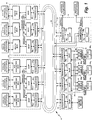
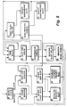
- FIG. 1 a block diagram of a distributed intelligence fault tolerant control-by-lightTM system 10 is shown comprising a deterministic network protocol for communication with a plurality of intelligent nodes 12, 14, 16, 18, 20. Such nodes 12-20 are connected to one or more bi-directional serial buses 21, 22, 23, each of said buses being a single fiber optic ring in the preferred embodiment.
- the number of nodes shown in Fig. 1 is only representative of a system and one skilled in the art will recognize that many node configurations are feasible depending on the particular system application.
- the system 10 is particularly useful for aircraft control by providing a low cost fault-tolerant control-by-lightTM distributed intelligence system for sensing and control across fault tolerant fiber optic networks.
- This provides a reduction of node cost, and is appropriate for use within a single equipment enclosure such as would typically be used for a node such as 18 or 20.
- network communications is reduced, autonomy for failure-recovery is enhanced, and reliability is improved.
- node computers In an aircraft application of the control-by-lightTM system 10, information flow between node computers can be minimized by distributing the control algorithms across the aircraft. It becomes possible to design a set of global data messages which pass across the communication network and correspond to aircraft state, physical parameters, and pilot commands. Individual nodes 12-20 may subscribe to a given set of messages depending on the function they perform. For example a thrust reverser control computer would subscribe to messages indicating whether the aircraft is airborne, the state of the engine, the state of the thrust lever, the state of the landing gear, and whether the pilot has commanded thrust reverser deployment. The thrust reverser control computer would publish data messages corresponding to the state of the reverser system.
- a crew alerting computer or subsystem would then subscribe to the status messages being published by the thrust reverser control computer as well as from other computers and subsystems distributed across the network. For critical control functions, messages must be received and voted upon across redundant networks before actions are taken at the point of actuation.
- the control-by-lightTM system 16 uses fiber optic serial data buses 21,22,23 which support multiple message transmitters.
- the bus network relies on a distributed media access technique to eliminate collisions, while at the same time not introducing any single points of failure.
- the advantages of a collision free network protocol are well known and are especially desirable for aircraft control systems or other critical control system applications.
- the bus network covering transceiver 26 1-N and buses 21,22,23 supports bi-directional communications over a single fiber by restricting communications to half duplex. This has the obvious benefit of reducing the cost to interconnect processing nodes to a single fiber.
- Each fiber optic transceiver 26 has two bi-directional, half duplex ports. This allows large networks to be created by connecting together processing elements into rings. Each node within the network or ring is connected to its neighbors by a bi-directional, half-duplex point to point fiber link. As a message propagates around the network, the message is regenerated at each node 12-20.
- every message is transmitted across the ring in both directions and is removed from the ring by the node which receives it from both directions. This method of transmission guarantees the delivery of all messages to all operating nodes, in the event of single hardware failures or fiber breaks.
- the DCCPs 28 1-N in the nodes 12-20 are powered from multiple sources to allow the system 10 to operate while an aircraft or other system is in an emergency reversionary state. Internally, the DCCPs 28 1-N utilize more than one power supply to allow for uninterrupted operation after a single hardware fault. Depending upon the application and the criticality of the function being implemented, multiple actuators and sensors can be used.
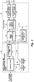
- the DCCP 28 provides the network and applications - specific processing within a node to process inputs from sensors and control devices intelligently and propagate control information across a network such as is shown in Fig. 1.
- the DCCP 28 comprises a VLSI chip 50 having three controllers 52 which include a media access control (MAC) processor, a network processor and an application processor; all three controllers 52 communicate on common address and data bus 60 to a random access memory (RAM) 56 and nonvolatile, programmable read only memory (PROM) 58.
- MAC media access control
- RAM random access memory
- PROM nonvolatile, programmable read only memory
- the three controllers 52 are coupled to a network communication port 54 which interfaces with the single fiber controller 64 of transceiver 26.
- the transceiver 26 and in particular the deterministic controller 72 is connected to the bus 60 via a bus extension 62.
- the RAM 56 provides general purpose storage of network messages and program variables.
- the PROM 58 stores programs and configuration data for the three controllers 52, including a media access control system routine described hereinafter for initiating a priority or a non-priority message onto the network bus 21,22,23.
- the operation of the VLSI chip 50 is described in a Neuron® Data Book dated February 1995 for the 3150 chip published by Echelon Corporation of Palo Alto, California which is incorporated herein by reference.
- the VLSI chip 50 may be embodied by Part No.
- the RAM may be embodied by Part No. CY7C199 manufactured by Cypress Semiconductor of San Jose, California.
- the PROM 58 may be embodied by Part No. AT29C256 manufactured by Atmel Corp., San Jose, California and programmed by Raytheon Company of Marlborough, Massachusetts.
- the transceiver 26 receives and transmits data over the bi-directional data bus 21 (and buses 22,23).
- Data packets from or to the fiber optic data bus 21 are passed through bi-directional photo diodes 68,70 which are coupled to a single fiber analog interface (SFAI) 66 in the preferred embodiment, or in an alternate embodiment through twisted pair or other media transceivers or through separate transmit photo diodes and receive photo diodes or laser diodes which require two fiber optic cables between each node and dual fiber analog interfaces although two fiber optic cables are required.
- the uni-directional diodes are less costly.
- the SFAI 66 converts low level analog signals from the bi-directional photo diodes 68,70 to CMOS or TTL levels and vice-versa.
- the bi-directional diodes 68,70 function in a "ping-pong" mode whereby they operate as either a receiver or a transmitter.
- the photodiodes 68,70 may also operate uni-directional whereby the operation is receive only or transmit only.
- Providing support for two ping-pong diodes allows for data transfers to occur in different communication topologies, e. g. a ring or star configuration.
- the SFAI 66 provides for rapid packet mode response from a quiet network condition to packet detection and the SFAI 66 provides for minimal turn around time from transmit to receive mode or from receive to transmit mode.
- the SFAI 66 is connected to a single fiber controller (SFC) 64 which is connected to a deterministic controller (DC) 72.
- SFC 64 interfaces with a communication port 54 of the DCCP 28 and the DC 72 interfaces with buses 60,62 of the DCCP 28.
- the combination of the SFC 64 and DC 72 is referred to as a single fiber controller-deterministic (SFC-D) 74.
- SFC-D 74 communicates bi-directionally (half-duplex) via the fiber optic data buses. It provides the control for the operation of the deterministic network protocol including a contention type protocol of the DCCP 28. Since the transceivers 26 1-N are operated in a circular or ring topology as shown in FIG.
- the SFC 64 provides an anti-recirculation timer to automatically prevent data packets from being recirculated by deleting such data packets from the network once they are received at all nodes 14-20.
- the SFC 64 restores signal quality at each node 14-20 and provides for pulse width distortion compensation resulting from non-symmetrical high-to-low and low-to-high propagation delays. It also provides optical power monitoring by measuring the magnitude of pulse width distortion which provides a relative implication of optical power strength.
- the SFC 64 restores the signal pulse width before sending the signal to the DCCP 28 or retransmitting the signal.
- Time slots 82 available for message or data packet communications.
- a Manchester - encoded data stream is used; however, other line protocols may be used as will be recognized by one of ordinary skill in the art.
- Each slot is a multiple of 12.8 microseconds in duration, although this duration will change according to the network transmission specification.
- the definition of slots 82 for each node 12-20 must be consistent with an overall network time line defined by a system designer.
- a node may be assigned more than one time slot.
- Time slots #1 to #N are the priority slots 83 1 -83 N where contention is prevented because of hardware synchronization across the network nodes 12-20, with periodic resynchronization using the beacon signal.
- the next slot is the non-priority slot 84 where the contention based protocol is allowed to function.
- the synchronization signal is referred to as the beacon and it may occur at time slots 81 and 86 in Fig. 3.
- the beacon is transported across the same medium as the subsequent data stream and does not require a separate line.
- the node that originates the beacon is referred to as the beacon master.
- the time slots 82 are measured from the time that a beacon is detected on the ring network buses 21, 22, 23.
- the guardband time slot 85 allows time for any network message started late in the non-priority time slot 84 to be completed.
- a beacon slot 86 which is allocated for transmission of the network beacon 80; the beacon slot 86 is implicit and is automatically added by the state machine of the transceiver 26.
- the network beacon is periodically transmitted by one node to loosely synchronize all nodes 12-20 on the network.
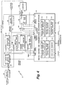
- a beacon detector 90 monitors incoming network data and generates a beacon detect 91 signal when the incoming data matches the beacon pattern defined hereinbefore.
- the beacon detector 90 comprises a shift register and comparator known to one of ordinary skill in the art.
- the beacon detect 91 signal is fed to a state machine 92 which controls the overall operation of the deterministic network protocol.
- the state machine 92 functions are described hereinafter.
- a beacon generator 95 When the state machine 92 generates a beacon request 93 signal, a beacon generator 95 generates the defined beacon pattern data on the network or bus 21.
- the beacon generator 95 comprises a counter and logic gates known to one of ordinary skill in the art.
- the deterministic control 72 comprises an application offset timer 94, a beacon watchdog timer 96, a slot counter 98 and a time since beacon counter 100.
- the application offset timer 94 comprises a 16 bit down counter which is loaded under state machine 92 control each time a beacon is received. The value loaded is supplied by a 16-bit application offset time constant register 110 in the DCCP interface 102. This register is loaded by the DCCP 28 during node initialization.
- the DCCP interface 102 provides a one -bit application offset status register 112 which permits the DCCP 28 to determine when the application offset timer has expired. This is used in conjunction with DCCP 28 application software to ensure that messages are issued only once per beacon period.
- Beacon Period is the sum of the duration of all priority slots 83 1 -83 N , plus the non-priority slot 84, the guardband slot 85, and the implicit beacon slot 81 as shown in Fig. 3.
- the beacon watchdog timer is an 8 bit down counter which is loaded under state machine 92 control each time a beacon is received by the beacon detector 90.
- the value loaded is supplied by an 8-bit beacon watchdog time constant register 116 in the DCCP interface 102. This register is loaded by the DCCP 28 during node initialization.
- the DCCP 28 interface 102 provides a one-bit beacon watchdog status register 118 which permits the DCCP to determine when the beacon watchdog timer 96 has expired. This permits the DCCP 28 to detect loss of beacons on the network. Synchronization among nodes and guard-banding of transmit periods is sufficient to allow nodes remain synchronized for several beacon periods, should the beacon master generation node fail. In this case software in the DCCP 28 elects a new beacon master, which assumes responsibility for beacon generation.
- the Slot Counter 98 comprises a 5-bit up counter which is reset to zero by the state machine 92 each time a beacon is received. It is used to select one of 32 locations in a slot RAM 106, and is advanced by one when commanded by the state machine 92.
- the time since beacon counter 100 comprises a 16-bit up counter which is reset to zero by the state machine 92 each time a beacon is received. This counter 100 counts at a 78 Khz (12.8 usec) rate for the preferred embodiment but one skilled in the art will recognize that this counter rate will vary depending on the data rate employed.
- the Slot RAM 106 comprises a 32 word x 16 bit static RAM which is used to define the allocation of network slots 82 within a beacon period. This RAM is loaded by the DCCP 28 during node initialization. For most of the entries, the most significant bit indicates whether the slot is allocated to this node or not. The lower 15 bits indicate the end time of the slot, with the least significant bit representing 12.8 microseconds. For the non-priority and guard band slot end times as shown in Fig. 3, all 16 bits are used to represent the slot end time.
- Entries into the slot RAM are as follows: (1) a series of 16 bit words defining the end times and ownership of all priority slots 83 1 -83 N ; (2) one 16 bit value defining the start time of the non-priority slot 84; this should be identical to the end time of the last priority slot; (3) one 16 bit value defining the end time of the non-priority slot; and (4) one 16 bit value defining the end time of the guard band slot.
- a compare 108 function comprises a 16 bit comparator plus gating logic which detects and indicates when the slot end time from the slot RAM 106 matches the time since last beacon. As described above, this is either a 15 or 16 bit comparison, depending on the current slot type.
- the DCCP Interface 102 provides the DCCP 28 with access to the functional elements of the deterministic controller 72. It includes address decoding and data path logic which permits the DCCP 28 to read and write registers to control and monitor the deterministic network protocol. This includes: the ability to read and write the application offset timer 94 and beacon watchdog timer 96, the ability to command entry into deterministic mode, the ability to read and write the Slot RAM 104 (when not in deterministic mode), and the ability to read status registers which indicate when a timer has expired or what the current slot type is.
- the deterministic control 72 located at each node 12-20 is initialized by application code running in the DCCP 28. This code writes into registers which define the application offset timer 94 and beacon watchdog timer 96 intervals. The operating mode and such items as whether the node is beacon master or beacon slave are also written at this time. It then writes a sequence of values into the slot RAM 104 which define the allocation of network slots 82. Once initialization is completed, the DCCP 28 commands entry into deterministic operating mode. While in deterministic operating mode, the DCCP interface 102 can no longer modify the slot RAM 106.
- the single fiber controller 64 and the deterministic controller 72 may be embodied by a single chip referred to as the single fiber control-deterministic 74, Part No. G649806-1, manufactured by Raytheon Company of Marlborough, Massachusetts.
- Fig. 5 shows a flow chart of the state machine 92 of Fig. 4 with each state identified by a hexadecimal number.
- the state machine 92 controls the deterministic network protocol operation.
- the state machine 92 enters state 0 or the entry state.
- the beacon master moves to state D and issues a beacon request to its beacon generator 95, and then proceeds to state 6. All other nodes (the beacon slaves) go directly from state 0 to state 6. In state 6, all nodes wait for a beacon detect indication.
- Software handles the case when the beacon master fails to initialize, and a back-up beacon master is turned on to issue beacons.
- Beacon detection produces the following effects: a) the state machine 92 is forced into state 7 (enter first slot); b) the slot counter 98 is cleared; c) the time since beacon counter 100 is cleared and begins counting up; d) the application offset timer 94 is loaded with its maximum interval and begins counting down; and e) the beacon watchdog timer 96 is loaded with its maximum interval and begins counting down.
- state machine will proceed to state 9 (enabled priority slot) if the next (first) slot is allocated to this node, and to state A (disabled (locked) priority slot) if it is not allocated to this node.
- state 9 and A the slot type is set to indicate "sync slot” or "sync lock” as appropriate.
- the state machine 92 then proceeds to state 2 (time delay).
- state machine 92 waits for a 12.8 microsecond interval to expire in this preferred embodiment. Each time this interval expires, the state machine 92 advances to state 3 (slot end check), where it compares the time since last beacon to the end time of the current slot. If the two do not match, the state machine 92 returns to state 2 and waits another 12.8 microseconds. If the two match, the current slot has ended.
- state 3 slot end check
- the state machine 92 will take one of the following paths:
- the deterministic controller 72 provides a slot type which is made available to the DCCP 28 through a 3-bit control register located in the DCCP interface 102.
- This register called the sync state register 114, is used to ensure that messages are transmitted only in the proper time slots as shown in Fig. 3.
- Two bits are used to define four slot types as follows:
- the use of the deterministic network protocol assumes that the system designer defines a fixed (or at least bounded) number of message transmissions by each node within a single beacon period, and a maximum execution time for the processing required in a beacon period. Each node is given enough time slots to meet the maximum transmission load.
- Application code is written for the application control processor of the DCCP 28 to ensure that this limit is not exceeded; the application offset timer 94 is provided for this purpose. This timer is loaded with a time constant upon receipt of a beacon (or when a beacon is expected and not received), and counts down to zero.
- the DCCP interface 102 provides a register 112 in which the application code can determine when the application offset timer 94 has expired.
- the preferred implementation is to set the application offset timer 94 to a value which is longer than the maximum processing time and shorter than the beacon period.
- the application code polls the application offset status register 112, waiting for the timer 94 to expire.
- the application code updates those network variables which it wishes to transmit during the next beacon period.
- the act of updating the network variables causes them to be placed in application buffers which are serviced by the network processor of the DCCP 28.
- the network processor is responsible for transmitting these network variables onto the network.
- the application offset timer 94 status is cleared to ensure that this action takes place only once per beacon period. Ensuring that the application code is aware of its message limits, and causing it to issue a known number of messages once per beacon period prevents the application processor of the DCCP 28 from issuing too many messages, which would eventually overflow the DCCP's 28 application buffers.
- Application code may send messages either within the priority slot(s) 83 1 -83 N which have been allocated to the node or in the non-priority contention based slot 84 which follows the priority slots.
- Network messages which are defined as priority messages are sent during priority slots, while others are sent during the non-priority slot.
- this limit is based on the factors on which this limit is based.
- the application code checks the status of the beacon watchdog timer whenever the application offset timer 94 expires, and if necessary initiates corrective action to select a new beacon master. If the beacon watchdog timer 96 expires, the selection of a new beacon master is accomplished by software. It is important that a beacon master be selected. The method of selection is not critical.
- Messages may be transmitted over the network buses 21,22,23 at any time during the non-priority slot.
- the guardband 85 as shown in Fig. 3 is provided within a beacon period to ensure that a message begun at the very end of the non-priority slot 84 will be completed before the start of the beacon time slot 86. Guardband slot length must accommodate the largest non-priority message in the system.
- the node 16 comprises three simplex nodes of DCCP 28/transceiver 26 elements wherein each transceiver 26 is coupled to one of the data buses 21,22,23.
- transceiver 262 is coupled to data bus 21
- transceiver 26 3 is coupled to data bus 22
- transceiver 264 is coupled to data bus 23.
- Each of the outputs form the three DCCPs 282, 283, 284 are fed to one of three intelligent voters 31,32,33.
- Each of the voters 31-33 generates an actuation signal if two of the three inputs to the voter nodes 31-33 agree.
- the actuation signal from each voter node 31-33 is used to control devices 34 1 ,34 2 ,34 3 wherein each of the devices in a preferred application comprises an electrically controlled hydraulic valve to be energized.
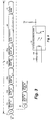
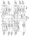
- a schematic diagram of a voter switching circuit 140 is shown in Fig. 7 which comprises three portions node A 142, node B 146, and node C 144.
- each circuit board comprises a transceiver 26, a DCCP 28, and one of each voter portion 142, 144, 146.
- a voter switching circuit 140 is constructed by taking portion 142 from one circuit board, portion 144 from a second circuit board, and portion 146 from the third circuit board.
- Three independent voter switching circuits 140 can be constructed from three circuit boards. Any two of the three DCCPs 28 2 ,28 3 ,28 4 must agree in order for the voter switching circuit 140 to transfer voltage (V) to the solenoid 154.
- All connections between the three node A 142, node B 146 and node C 144 are made using optically isolated devices.
- the isolation provided protects each DCCP 28 2 ,28 3 ,28 4 from faults in the voltage (V) being switched by the relay, and protects the DCCPs from each other. In this manner, faults external to a DCCP, even those which damage this voter or render it inoperable, do not damage the DCCP or prevent it from carrying out other functions
- the isolation further permits this voter switching circuit 140 to be used as either a "high side” or a "low side” switch. If other considerations require, the voter switching circuit 140 can be placed either between voltage (V) and the solenoid, or between the solenoid and ground.
- the optically isolated relays 148-151 may be embodied by part number PVDZ172 manufactured by International Rectifiers of El Segundo, California.
- the distributed voter switching circuit 140 includes provisions for performance monitoring and built-in test. This is provided by optically isolated receivers 156 1 -156 6 which monitor the voltage across each solid state optically isolated relay 148-151. They are arranged as shown in Fig. 7. Optically isolated receiver 156 1 is connected across terminals 160 and 161 of optically isolated relay A 148. Optically isolated receiver 156 2 is connected across terminals 168 and 169 of optically isolated relay C 151. Optically isolated receiver 156 3 is connected across terminals 166 and 167 of optically isolated relay B1 149.
- Optically isolated receiver 156 4 is connected across terminals 162 and 163 of optically isolated relay B2 150.
- Optically isolated receiver 156 5 is connected across the terminals 168 and 169 of optically isolated relay C 151.
- Optically isolated receiver 156 6 is connected to the power supply voltage (V) and to the junction of terminal 162 of optically isolated relay B2, terminal 164 of diode 152 and terminal 161 of optically isolated relay A 148.
- each optically isolated receiver 156 1 -156 6 is shown in Figure 8.
- the resistor 157 and diode 158 values are chosen such that the leakage current through the receiver is not sufficient to activate the receiver.
- the receivers 156 1 -156 6 will only be activated if a closed relay 148-151 provides part of the current path.
- the optically isolated relays 148-151 The most common failure mode of the optically isolated relays 148-151 is to fail in a short circuit state.
- the optically isolated receivers 156 1 -156 6 are configured such that the closure of a relay controlled by one of DCCPs 28 2 , 28 3 , 28 4 can be detected by each of the other two DCCPs using built-in-test software monitoring the receivers 156 1 -156 6 .
- the receivers 156 1 -156 6 can also be used to perform a test of the relays which is coordinated by any DCCP 28 which has access to all three DCCP 28 2 , 28 3 , 28 4 such as intelligent node 20 of Figure 1. This test may be performed off line or when system requirements permit as an on line background diagnostic test.
- the Table describes how each of the potential faults in the voter switching circuit 140 is detected by the monitoring functions of the optically isolated receivers 156 1 -156 6 provided. Those items which are testable "any time” may be tested by checking the monitoring points at a time when all relays are expected to be open. Those items testable during Built-In-Self-Test "BIST' may be tested only when it is safe to close certain relays and monitor the voter switching circuit 140 as a coordinated activity involving all three threads 142,144,146. This is expected to be performed either as part of pre-flight self test/diagnostics, or in a maintenance mode.
- Monitors 156 2 and 156 5 should detect a current path and monitor 156 4 should not. If 152 is shorted, monitor 156 4 will detect a current path. Diode 147 open circuit Not detectable This is a protection diode only Diode 152 open circuit BIST Attempt to close 148. Monitors 156 4 , 156 2 and 156 5 should all detect a current path. If diode 152 is open, monitors 156 2 and 156 5 will not detect the current path.
Abstract
Description
- This invention relates to an apparatus and method for sending and receiving data over a bi-directional bus of a distributed intelligence system and in particular to a deterministic network protocol which provides for a combination of a contention protocol and a time slot allocation protocol.
- A bi-directional bus architecture is composed of multiple transmitter/receiver pairs connected over a network via a time multiplexed data channel. Within a bi-directional bus architecture, some method is used to regulate the transmitters access to the data channel. Controlling access to the data channel may be done via a single or redundant central bus arbiter or in a distributed manner where each transmitter node of a network has the means to arbitrate usage of the data channel.
- In the prior art there are four basic bus access protocols suitable for controlling access to bi-directional buses such as contention, time slot allocation, command/response and token passing. Such protocols may be implemented in hardware, software or a combination of both.
- Contention based protocols allow data collisions to occur as a normal course of events. The data is then retransmitted after hardware or software detects the collision usually after either a prioritized or a random period of time elapses. This protocol offers the lowest minimum data latencies under light network loads, but can collapse under heavy network loads due to an excessive number of collisions and networks.
- The time slot allocation protocol pre-allocates network bandwidth to each user. All users are allocated a unique time slot during which they may transmit a data packet. However, this protocol suffers from a large minimum data latency under light network loads, but will not collapse under heavy loads. This protocol provides the advantages of guaranteeing a maximum data latency and has as a consequence a reduced data throughput.
- The command response protocol requires the use of a central arbiter to allocate bus bandwidth to individual users. Although the central arbiter simplifies the design of a bus interface unit for each node of a network, it has the disadvantage of providing a potential central point of failure for a network.
- Token passing protocols are similar to the time slot allocation protocol. Access to the data channel is controlled by passing a "token" as opposed to time based allocation. The characteristics of the two protocols are very similar.
- One prior art approach to a data channel protocol for a time division communication network which dynamically switches among contention (ALOHA), reservation, and fixed assignment (TDMAs) protocols as a function of traffic on the channel is described in U.S. Patent No. 5,012,469, issued April 30, 1991 to Karamvir Sardana. This class of protocols is referred to as Aloha-Reservation-TDMA or ART class protocols. ALOHA protocols, typically used on satellite communications networks (SCNs), anticipate and deal with collisions in order to minimize the probability of their occurrence. The goal of ALOHA is to maximize throughput (network utilization) while minimizing average message delay. TDMA-Reservation protocols (TDMA-Res) allow stations (nodes) on a network to dynamically request time slots in which to transmit data. This method avoids collisions, but sacrifices throughput by allocating a portion of each time slot to the passing of reservation requests.
- Another prior art approach is described in U.S. Patent No. 5,297,141 issued March 22, 1994 to Marek J. Fridrich et al. and assigned to Echelon Systems Corp. Fridrich teaches a network communication protocol that provides for improved reliable multicast messaging wherein messages may be reliably multicast to members of a multicast group and each member of the group responds to receipt of the message with an acknowledgment message. In the event one of the members of a group does not respond to a message with an acknowledgment, a reminder message is sent; hence, this protocol provides a random waiting time selected by the node before it attempts to send a message again. This protocol method tends to avoid collisions, but collisions still occur and critical messages do not have a concisely bounded latency.
- There is a requirement particularly in aircraft applications for a distributed processing system to handle in a timely manner both critical and non-critical data messages. Critical messages require that all data latencies must be bounded to some known and predictable value. Non-critical messages are those for which a bounded data latency is not required. The present invention satisfies both of these requirements.
- Accordingly, it is therefore an object of the invention to provide a distributed fault tolerant low-cost control system having a deterministic network protocol for communication with a plurality of processing nodes interconnected by at least one bi-directional fiber optic bus (preferred embodiment) or other transceiver media.
- It is a further object of this invention to provide a deterministic network protocol in a distributed intelligence control system for handling priority and non-priority messages by a combination of time slot and contention based protocols, thereby maximizing utilization of the network without impacting data latencies.
- It is a further object of this invention to provide synchronization means at each of the plurality of processing nodes with one of the nodes being assigned to generate a beacon master synchronization signal in order to prevent a single point failure within the distributed intelligence system.
- The objects are further accomplished by providing a combination of a distributed intelligence control system comprising a plurality of nodes interconnected by at least one bi-directional data bus, each of the nodes comprises transceiver means for transmitting and receiving messages via the data bus, each of the nodes comprises processor means coupled to the transceiver means for processing said messages to and from said transceiver means, control means included in each of the transceiver means for generating a timing beacon in a predetermined one of the nodes for transmission to each of the other nodes via the data bus, and the control means comprises means for generating a plurality of time slots within a time period of the timing beacon wherein each of the nodes is preassigned to at least one of the time slots for transmitting critical messages at a predetermined time and at least one of the time slots being provided for contention by the plurality of nodes for transmitting non-critical messages. The distributed control systems comprises two or more of the bi-directional data buses for fault tolerant operation, depending upon application and criticality. The bi-directional data bus comprises a fiber optic means or other media means for providing a transmission medium. The transceiver means in the preferred embodiment comprises bi-directional photo diodes or other devices for transmitting and receiving messages via said data bus. The timing beacon comprises a pulse pattern recognized only by the control means and transparent to the processor means, the pulse pattern being recognized as an invalid data pattern.
- The objects are further accomplished by providing in a network having a plurality of nodes, each of said nodes interconnected by at least one communication medium, a network protocol comprising, transceiver means in each of the nodes coupled to the communication medium for transmitting and receiving messages, processor means coupled to each of the transceiver means in each of the nodes for processing the messages to and from the communication medium, means in each of the nodes for generating and detecting a timing beacon for synchronizing the nodes, one of the nodes being preassigned to generate the timing beacon, the timing beacon comprises a pulse pattern recognized only by the nodes and transparent to the processor means, the pulse pattern not recognized as a valid data pattern, means is each of the nodes for generating a plurality of time slots during a time period of the timing beacon, each of the nodes being preassigned at least one of the time slots for transmitting critical messages and at least one of the time slots being provided for contention by the plurality of nodes to transmit non-critical messages. The communication medium comprises a fiber optic cable or other media for transmitting and receiving messages. The transceiver means in the preferred embodiment comprises bi-directional photo diodes for transmitting and receiving messages via said communication medium. Uni-directional photo diodes for transmitting and receiving messages via the communication medium, or other transceiver technologies such as twisted pair or power line modulation may also be used. The means for generating a plurality of time slots comprises a state machine for controlling the network protocol for transmitting and receiving the messages via the communication medium.
- The objects are further accomplished by providing a network having a deterministic network protocol comprising a plurality of nodes, each of the nodes interconnected by at least three of a plurality of communication media for fault tolerant operation, transceiver means included in each of the nodes and connected to the plurality of communication media, for transmitting and receiving messages, processing means in each of the nodes coupled to the transceiver means for processing the messages to and from the communication media, means in each of the nodes for generating and detecting a timing beacon for synchronizing the nodes, one of the nodes being preassigned to generate the timing beacon, and means in each of the nodes for generating a plurality of time slots during a time period of the timing beacon, each of the nodes being preassigned at least one of the time slots for transmitting critical messages, and at least one of the time slots provides for contention by the plurality of nodes to transmit non-critical messages. The communication medium in the preferred embodiment comprises a fiber optic means for transmitting and receiving messages. The transceiver means comprises bi-directional photo diodes coupled to the communication media for transmitting and receiving messages via the communication media. The means for generating a plurality of time slots comprises a state machine for controlling a network protocol for transmitting and receiving the messages via the communication media.
- The objects are further accomplished by a method of providing a distributed intelligence control system comprising the steps of, interconnecting a plurality of nodes by at least one bi-directional data bus, transmitting and receiving messages via the data bus with transceiver means in each of the plurality of nodes, processing the messages to and from the transceiver means with processor means coupled to the transceiver means, generating a timing beacon in a predetermined one of the nodes for transmission to each of the other nodes via the data bus with control means in each of the transceiver means, and generating a plurality of time slots within a time period of the timing beacon wherein each of the nodes is preassigned at least one of the time slots for transmitting critical messages at a predetermined time and at least one of the time slots is provided for contention by the plurality of nodes for transmitting non-critical messages.
- Other and further features and advantages of the invention will become apparent in connection with the accompanying drawings wherein:
- FIG. 1 is a block diagram of a fault-tolerant distributed control-by-light™ system employing the present invention;
- FIG. 2 is a block diagram of a transceiver coupled to a digital control and communication processor as shown in FIG. 1;
- FIG. 3 is an illustration of the time slot arrangement of the deterministic protocol within a beacon signal period;
- FIG. 4 is a detailed block diagram of the deterministic control portion of the transceiver as shown in FIG. 2;
- FIG. 5 is a block diagram of the state machine shown in FIG. 3;
- FIG. 6 is a flow chart of the media access algorithm embodied in the PROM of the DCCP in FIG. 2;
- FIG. 7 is a schematic diagram of a voter switching circuit employed in the voter node of FIG. 1; and
- FIG. 8 is a schematic representation of an optically isolated receiver shown in FIG. 7.
- Referring to FIG. 1, a block diagram of a distributed intelligence fault tolerant control-by-
light™ system 10 is shown comprising a deterministic network protocol for communication with a plurality ofintelligent nodes serial buses system 10 is particularly useful for aircraft control by providing a low cost fault-tolerant control-by-light™ distributed intelligence system for sensing and control across fault tolerant fiber optic networks. Thesystem 10 uses the distributed local intelligent nodes 12-20 to sense and/or control physical parameters and actuators with messages being passed across redundantserial buses transceivers 261-N and eachtransceiver 261-N is connected to a digital control and communication processor (DCCP) 281-N. Each combination of a transceiver and a DCCP may be referred to as a processing element. Thissystem 10 in an aircraft application replaces mechanical, hydraulic and electrical controls now used by aircraft pilots to control, monitor, and display primary and secondary flight control functions and it provides substantial weight, cost, safety and performance advantages over current techniques. Thissystem 10 is applicable to control of other systems besides aircraft such as ground transportation, surface and submarine ships, spacecraft, utilities and industrial process controls. Although the data bus media in the present preferred embodiment is implemented with fiber optics, the deterministic network protocol is applicable to other medias such as twisted pair wiring and power lines. -
Node 12 is representative of a simplex control node,node 14 is representative of a dual control node, andnode 16 comprises triple control nodes including fault tolerant intelligent voters which are described hereinafter.Node 18 is a fault tolerant, fail fast, simple digital node for interfacing with digital sensors/actuators andnode 20 is a fault tolerant, fail fast, triple analog node for interfacing with analog sensors/actuators. The broadcast link shown innode 18 andnode 20 is a bi-directional serial bus similar tobuses bi-directional photodiodes Fiber Analog Interface 66 of Figure 2 with an optically isolated electrical interface. This provides a reduction of node cost, and is appropriate for use within a single equipment enclosure such as would typically be used for a node such as 18 or 20. By distributing the system intelligence to every node, network communications is reduced, autonomy for failure-recovery is enhanced, and reliability is improved. - In an aircraft application of the control-by-
light™ system 10, information flow between node computers can be minimized by distributing the control algorithms across the aircraft. It becomes possible to design a set of global data messages which pass across the communication network and correspond to aircraft state, physical parameters, and pilot commands. Individual nodes 12-20 may subscribe to a given set of messages depending on the function they perform. For example a thrust reverser control computer would subscribe to messages indicating whether the aircraft is airborne, the state of the engine, the state of the thrust lever, the state of the landing gear, and whether the pilot has commanded thrust reverser deployment. The thrust reverser control computer would publish data messages corresponding to the state of the reverser system. A crew alerting computer or subsystem would then subscribe to the status messages being published by the thrust reverser control computer as well as from other computers and subsystems distributed across the network. For critical control functions, messages must be received and voted upon across redundant networks before actions are taken at the point of actuation. - A node computer such as the
DCCP 281-N may be programmed to provide local loop closure on an actuator. By associating the software required to control the actuator with its actuator, and by standardizing on a network protocol, it becomes much easier to interface components across the aircraft, while also enhancing flexibility and configurability. Partitioning the software also aids in minimizing maintenance and certification costs. - The control-by-
light™ system 16 uses fiber opticserial data buses - The bus
network covering transceiver 261-N andbuses fiber optic transceiver 26 has two bi-directional, half duplex ports. This allows large networks to be created by connecting together processing elements into rings. Each node within the network or ring is connected to its neighbors by a bi-directional, half-duplex point to point fiber link. As a message propagates around the network, the message is regenerated at each node 12-20. To prevent a single node or link failure from disabling the network, every message is transmitted across the ring in both directions and is removed from the ring by the node which receives it from both directions. This method of transmission guarantees the delivery of all messages to all operating nodes, in the event of single hardware failures or fiber breaks. - The control-by-light™ system uses combinations of traditional fault tolerant techniques including hardware redundancy, software redundancy, temporal redundancy, and information redundancy. Flight critical functions are implemented using nodes composed of multiple processing elements. Hardware and software voters are utilized to ensure the validity of commands. Multiple,
independent data buses - The DCCPs 281-N in the nodes 12-20 are powered from multiple sources to allow the
system 10 to operate while an aircraft or other system is in an emergency reversionary state. Internally, theDCCPs 281-N utilize more than one power supply to allow for uninterrupted operation after a single hardware fault. Depending upon the application and the criticality of the function being implemented, multiple actuators and sensors can be used. - A control-by-light™ system enforces the partitioning of software across multiple processing elements thereby creating independent software executables which implement an easily definable function. All the independent routines communicate via a well defined interface. The software partitioning allows for exhaustive testing of the software, providing a level of confidence which is often difficult and expensive to achieve on more centralized systems.
- Referring to Fig. 2 block diagrams of the digital control and communication processor (DCCP) 28 and the
transceiver 26 forming a processing element are shown. TheDCCP 28 provides the network and applications - specific processing within a node to process inputs from sensors and control devices intelligently and propagate control information across a network such as is shown in Fig. 1. TheDCCP 28 comprises aVLSI chip 50 having threecontrollers 52 which include a media access control (MAC) processor, a network processor and an application processor; all threecontrollers 52 communicate on common address anddata bus 60 to a random access memory (RAM) 56 and nonvolatile, programmable read only memory (PROM) 58. The threecontrollers 52 are coupled to anetwork communication port 54 which interfaces with thesingle fiber controller 64 oftransceiver 26. Thetransceiver 26 and in particular thedeterministic controller 72 is connected to thebus 60 via abus extension 62. TheRAM 56 provides general purpose storage of network messages and program variables. ThePROM 58 stores programs and configuration data for the threecontrollers 52, including a media access control system routine described hereinafter for initiating a priority or a non-priority message onto thenetwork bus VLSI chip 50 is described in a Neuron® Data Book dated February 1995 for the 3150 chip published by Echelon Corporation of Palo Alto, California which is incorporated herein by reference. TheVLSI chip 50 may be embodied by Part No. MC143150 manufactured by Motorola Inc. of Phoenix, Arizona. Other similar microcontrollers with network communication capabilities may also be used to implement theVLSI Chip 50. The RAM may be embodied by Part No. CY7C199 manufactured by Cypress Semiconductor of San Jose, California. ThePROM 58 may be embodied by Part No. AT29C256 manufactured by Atmel Corp., San Jose, California and programmed by Raytheon Company of Marlborough, Massachusetts. - Referring to Figures 1 and 2, the
transceiver 26 receives and transmits data over the bi-directional data bus 21 (andbuses 22,23). Data packets from or to the fiberoptic data bus 21 are passed throughbi-directional photo diodes SFAI 66 converts low level analog signals from thebi-directional photo diodes bi-directional diodes photodiodes SFAI 66 provides for rapid packet mode response from a quiet network condition to packet detection and theSFAI 66 provides for minimal turn around time from transmit to receive mode or from receive to transmit mode. TheSFAI 66 converts the inputs of thephoto diodes bi-directional photo diodes SFAI 66 may be embodied by Part No. G641848-1 manufactured by Raytheon Company of Marlborough, Massachusetts. Thebi-directional photo diodes optic data buses - The
SFAI 66 is connected to a single fiber controller (SFC) 64 which is connected to a deterministic controller (DC) 72. TheSFC 64 interfaces with acommunication port 54 of theDCCP 28 and theDC 72 interfaces withbuses DCCP 28. The combination of theSFC 64 andDC 72 is referred to as a single fiber controller-deterministic (SFC-D) 74. The SFC-D 74 communicates bi-directionally (half-duplex) via the fiber optic data buses. It provides the control for the operation of the deterministic network protocol including a contention type protocol of theDCCP 28. Since thetransceivers 261-N are operated in a circular or ring topology as shown in FIG. 1, theSFC 64 provides an anti-recirculation timer to automatically prevent data packets from being recirculated by deleting such data packets from the network once they are received at all nodes 14-20. TheSFC 64 restores signal quality at each node 14-20 and provides for pulse width distortion compensation resulting from non-symmetrical high-to-low and low-to-high propagation delays. It also provides optical power monitoring by measuring the magnitude of pulse width distortion which provides a relative implication of optical power strength. TheSFC 64 restores the signal pulse width before sending the signal to theDCCP 28 or retransmitting the signal. - Referring now to FIG. 2 and FIG. 3, Fig. 2 shows that the
deterministic controller 72 is connected to thesingle fiber controller 64 and also interfaces with theDCCP 28. TheDC 72 provides the control for a network response in a guaranteed time period by the unique combination of time slot and contention based communications. The use of the deterministic network protocol permits multiple nodes 10-20 of Fig. 1 to transmit data without chance of message collisions. Message collisions are undesirable since they result in the failure of the network to deliver these messages in a concisely bounded and predictable manner. Collision detection and/or message acknowledgment protocols could be used to detect failure of message delivery, but these methods do not provide a guarantee of system response time. The deterministic network protocol allows the system designer to place a concise upper bound on message delivery time. Fig. 3 shows a plurality oftime slots 82 available for message or data packet communications. In the present embodiment, a Manchester - encoded data stream is used; however, other line protocols may be used as will be recognized by one of ordinary skill in the art. Each slot is a multiple of 12.8 microseconds in duration, although this duration will change according to the network transmission specification. The definition ofslots 82 for each node 12-20 must be consistent with an overall network time line defined by a system designer. A node may be assigned more than one time slot.Time slots # 1 to #N are the priority slots 831-83N where contention is prevented because of hardware synchronization across the network nodes 12-20, with periodic resynchronization using the beacon signal. The next slot is thenon-priority slot 84 where the contention based protocol is allowed to function. In order to provide synchronization, it is necessary to transport a synchronization signal across the network. Each node 12-20 provides for transmitting the synchronization signal, detecting the synchronization signal, and provides management of which node is in charge of originating this signal. The synchronization signal is referred to as the beacon and it may occur attime slots time slots 82 are measured from the time that a beacon is detected on thering network buses guardband time slot 85 allows time for any network message started late in thenon-priority time slot 84 to be completed. Following theguardband slot 85 is abeacon slot 86 which is allocated for transmission of the network beacon 80; thebeacon slot 86 is implicit and is automatically added by the state machine of thetransceiver 26. The network beacon is periodically transmitted by one node to loosely synchronize all nodes 12-20 on the network. - The beacon pattern is chosen to satisfy the following requirements: (a) the beacon pattern must be distinct, i.e. it must be a pattern which cannot occur during transmission of a network message; (b) the beacon pattern must not adversely impact the operation of the digital control and communication processor (DCCP); and (c) the beacon pattern should be relatively short so as not to significantly reduce the time available for network messages. For the Manchester line code employed in the present embodiment, the beacon pattern selected to meet these requirements is defined as follows:
- 1. TTL high (LED on) for 2000 nanoseconds.
- 2. TTL low (LED off) for 400 nanoseconds.
- 3. TTL high (LED on) for 400 nanoseconds.
- 4. TTL low (LED off) for 400 nanoseconds.
- 5. TTL high (LED on) for 400 nanoseconds.
- 6. TTL low (LED off) for 400 nanoseconds.
- 7. TTL high (LED on) for 2400 nanoseconds.
- Referring now to Fig. 4, a block diagram of the
deterministic control 72 portion of thetransceiver 26 is shown. Abeacon detector 90 monitors incoming network data and generates a beacon detect 91 signal when the incoming data matches the beacon pattern defined hereinbefore. Thebeacon detector 90 comprises a shift register and comparator known to one of ordinary skill in the art. The beacon detect 91 signal is fed to astate machine 92 which controls the overall operation of the deterministic network protocol. Thestate machine 92 functions are described hereinafter. When thestate machine 92 generates abeacon request 93 signal, abeacon generator 95 generates the defined beacon pattern data on the network orbus 21. Thebeacon generator 95 comprises a counter and logic gates known to one of ordinary skill in the art. Thedeterministic control 72 comprises an application offsettimer 94, abeacon watchdog timer 96, aslot counter 98 and a time sincebeacon counter 100. - The application offset
timer 94 comprises a 16 bit down counter which is loaded understate machine 92 control each time a beacon is received. The value loaded is supplied by a 16-bit application offset timeconstant register 110 in theDCCP interface 102. This register is loaded by theDCCP 28 during node initialization. TheDCCP interface 102 provides a one -bit application offsetstatus register 112 which permits theDCCP 28 to determine when the application offset timer has expired. This is used in conjunction withDCCP 28 application software to ensure that messages are issued only once per beacon period. Beacon Period is the sum of the duration of all priority slots 831-83N, plus thenon-priority slot 84, theguardband slot 85, and theimplicit beacon slot 81 as shown in Fig. 3. - The beacon watchdog timer is an 8 bit down counter which is loaded under
state machine 92 control each time a beacon is received by thebeacon detector 90. The value loaded is supplied by an 8-bit beacon watchdog timeconstant register 116 in theDCCP interface 102. This register is loaded by theDCCP 28 during node initialization. TheDCCP 28interface 102 provides a one-bit beaconwatchdog status register 118 which permits the DCCP to determine when thebeacon watchdog timer 96 has expired. This permits theDCCP 28 to detect loss of beacons on the network. Synchronization among nodes and guard-banding of transmit periods is sufficient to allow nodes remain synchronized for several beacon periods, should the beacon master generation node fail. In this case software in theDCCP 28 elects a new beacon master, which assumes responsibility for beacon generation. - The
Slot Counter 98 comprises a 5-bit up counter which is reset to zero by thestate machine 92 each time a beacon is received. It is used to select one of 32 locations in aslot RAM 106, and is advanced by one when commanded by thestate machine 92. The time sincebeacon counter 100 comprises a 16-bit up counter which is reset to zero by thestate machine 92 each time a beacon is received. Thiscounter 100 counts at a 78 Khz (12.8 usec) rate for the preferred embodiment but one skilled in the art will recognize that this counter rate will vary depending on the data rate employed. - The
Slot RAM 106 comprises a 32 word x 16 bit static RAM which is used to define the allocation ofnetwork slots 82 within a beacon period. This RAM is loaded by theDCCP 28 during node initialization. For most of the entries, the most significant bit indicates whether the slot is allocated to this node or not. The lower 15 bits indicate the end time of the slot, with the least significant bit representing 12.8 microseconds. For the non-priority and guard band slot end times as shown in Fig. 3, all 16 bits are used to represent the slot end time. Entries into the slot RAM are as follows: (1) a series of 16 bit words defining the end times and ownership of all priority slots 831-83N; (2) one 16 bit value defining the start time of thenon-priority slot 84; this should be identical to the end time of the last priority slot; (3) one 16 bit value defining the end time of the non-priority slot; and (4) one 16 bit value defining the end time of the guard band slot. - A
multiplexer 104 provides a path by which theDCCP 28 can directly address theslot RAM 106 during initialization. A deterministic mode control register 120 in theDCCP Interface 102 permits theDCCP 28 to command entry into the deterministic mode. When not in the deterministic mode, theDCCP 28 has access to theSlot RAM 106 to perform initialization. - A compare 108 function comprises a 16 bit comparator plus gating logic which detects and indicates when the slot end time from the
slot RAM 106 matches the time since last beacon. As described above, this is either a 15 or 16 bit comparison, depending on the current slot type. - The
DCCP Interface 102 provides theDCCP 28 with access to the functional elements of thedeterministic controller 72. It includes address decoding and data path logic which permits theDCCP 28 to read and write registers to control and monitor the deterministic network protocol. This includes: the ability to read and write the application offsettimer 94 andbeacon watchdog timer 96, the ability to command entry into deterministic mode, the ability to read and write the Slot RAM 104 (when not in deterministic mode), and the ability to read status registers which indicate when a timer has expired or what the current slot type is. - The
deterministic control 72 located at each node 12-20 is initialized by application code running in theDCCP 28. This code writes into registers which define the application offsettimer 94 andbeacon watchdog timer 96 intervals. The operating mode and such items as whether the node is beacon master or beacon slave are also written at this time. It then writes a sequence of values into theslot RAM 104 which define the allocation ofnetwork slots 82. Once initialization is completed, theDCCP 28 commands entry into deterministic operating mode. While in deterministic operating mode, theDCCP interface 102 can no longer modify theslot RAM 106. Thesingle fiber controller 64 and thedeterministic controller 72 may be embodied by a single chip referred to as the single fiber control-deterministic 74, Part No. G649806-1, manufactured by Raytheon Company of Marlborough, Massachusetts. - Referring now to Fig. 4 and Fig. 5, Fig. 5 shows a flow chart of the
state machine 92 of Fig. 4 with each state identified by a hexadecimal number. Thestate machine 92 controls the deterministic network protocol operation. When the deterministic mode is entered, thestate machine 92 enters state 0 or the entry state. The beacon master moves to state D and issues a beacon request to itsbeacon generator 95, and then proceeds tostate 6. All other nodes (the beacon slaves) go directly from state 0 tostate 6. Instate 6, all nodes wait for a beacon detect indication. Software handles the case when the beacon master fails to initialize, and a back-up beacon master is turned on to issue beacons. Beacon detection produces the following effects: a) thestate machine 92 is forced into state 7 (enter first slot); b) theslot counter 98 is cleared; c) the time sincebeacon counter 100 is cleared and begins counting up; d) the application offsettimer 94 is loaded with its maximum interval and begins counting down; and e) thebeacon watchdog timer 96 is loaded with its maximum interval and begins counting down. - From
state 7, the state machine will proceed to state 9 (enabled priority slot) if the next (first) slot is allocated to this node, and to state A (disabled (locked) priority slot) if it is not allocated to this node. In states 9 and A, the slot type is set to indicate "sync slot" or "sync lock" as appropriate. Thestate machine 92 then proceeds to state 2 (time delay). - In
state 2, thestate machine 92 waits for a 12.8 microsecond interval to expire in this preferred embodiment. Each time this interval expires, thestate machine 92 advances to state 3 (slot end check), where it compares the time since last beacon to the end time of the current slot. If the two do not match, thestate machine 92 returns tostate 2 and waits another 12.8 microseconds. If the two match, the current slot has ended. - From
state 3, thestate machine 92 will take one of the following paths: - a) If the slot which ended was a priority slot and the next slot is also a priority slot, the
state machine 92 will pass through state 4 (guardband check) and intostate 5, (next slot set up - where the slot counter is incremented), then into state B (non-priority check). Since thenew slot RAM 106 location contains a different time value then the prior location, thestate machine 92 moves to state F (enter new slot). State F is similar tostate 7. From state F, thestate machine 92 will move to state 9 or A based on slot ownership, and the process described above will repeat. - b) If the slot which ended was a priority slot and the next slot is the non-priority slot, the state machine will pass through
state 4 and into state 5 (where the slot counter in incremented) and then into state B. Since the next RAM location has the same time value as the prior location, thestate machine 92 moves to state C (enter non-priority slot). In state C, the slot type is set to indicate "sync open." Thestate machine 92 then moves tostate 2 and begins waiting for the end of the non-priority slot. - c) If the slot which ended was the non-priority slot, the
state machine 92 passes throughstate 4 and into state 5 (where the slot counter is incremented), and then into state E (enter guardband slot). In state E, a flag is set to indicate that the guardband has been entered, and the slot type is set to indicate "sync lock." Thestate machine 92 then moves tostate 2 and begins waiting for the end of the guardband. - d) If the slot which ended was the guardband, the
state machine 92 passes throughstate 4 and into state 1 (beacon slot delay). Instate 1, thestate machine 92 waits a fixed amount of time. This time is 12.8 microseconds for a slave node, or the full length of the beacon slot. Slave nodes then proceed through state 8 (beacon node check) intostate 7, assuming that a beacon arrived when expected. If a beacon arrived early or late, thestate machine 92 would be forced intostate 7 and resynchronized. A master waits approximately 6.4 microseconds instate 1, and then proceeds throughstates 8 and D and intostate 6, where it waits for the beacon. This accounts for the fact that it takes the master 6.4 microseconds to generate a beacon. If a beacon is generated and seen by all nodes, all are resynchronized intostate 7 at the time of beacon detection. Any node which misses the beacon for some reason has made an attempt to synchronize itself, and should be in error by oscillator accuracy differences only. In this way, all nodes enterstate 7 at about the same time. - As described in the
state machine 92 description above, thedeterministic controller 72 provides a slot type which is made available to theDCCP 28 through a 3-bit control register located in theDCCP interface 102. This register, called thesync state register 114, is used to ensure that messages are transmitted only in the proper time slots as shown in Fig. 3. Two bits are used to define four slot types as follows: - Sync Slot:
- A deterministic slot allocated to a particular node; one priority message may be transmitted.
- Sync Lock:
- A deterministic slot not allocated to a particular node or nodes; transmission is prohibited. Also used during the guardband to prevent all transmissions.
- Sync Open:
- This state is for the non-priority slot time; all available non-priority messages may be transmitted.
- Normal:
- The network is running in non-deterministic mode.
- The use of the deterministic network protocol assumes that the system designer defines a fixed (or at least bounded) number of message transmissions by each node within a single beacon period, and a maximum execution time for the processing required in a beacon period. Each node is given enough time slots to meet the maximum transmission load. Application code is written for the application control processor of the
DCCP 28 to ensure that this limit is not exceeded; the application offsettimer 94 is provided for this purpose. This timer is loaded with a time constant upon receipt of a beacon (or when a beacon is expected and not received), and counts down to zero. TheDCCP interface 102 provides aregister 112 in which the application code can determine when the application offsettimer 94 has expired. The preferred implementation is to set the application offsettimer 94 to a value which is longer than the maximum processing time and shorter than the beacon period. After completing the processing required during a period, the application code polls the application offsetstatus register 112, waiting for thetimer 94 to expire. Once the application offsettimer 94 has expired, the application code updates those network variables which it wishes to transmit during the next beacon period. The act of updating the network variables causes them to be placed in application buffers which are serviced by the network processor of theDCCP 28. The network processor is responsible for transmitting these network variables onto the network. The application offsettimer 94 status is cleared to ensure that this action takes place only once per beacon period. Ensuring that the application code is aware of its message limits, and causing it to issue a known number of messages once per beacon period prevents the application processor of theDCCP 28 from issuing too many messages, which would eventually overflow the DCCP's 28 application buffers. - Application code may send messages either within the priority slot(s) 831-83N which have been allocated to the node or in the non-priority contention based
slot 84 which follows the priority slots. Network messages which are defined as priority messages are sent during priority slots, while others are sent during the non-priority slot. - The
beacon watchdog timer 96 is provided to detect the loss of the beacons which synchronize the network. This timer is loaded with a time constant upon receipt of a beacon, and counts down to zero. TheDCCP interface 102 provides aregister 118 in which the application code can determine when thebeacon watchdog timer 96 has expired. If beacons continue to arrive as expected, this timer is continually reloaded, and never expires. The preferred implementation is to set thebeacon watchdog timer 96 to a value significantly greater than one beacon period. Since nodes attempt to maintain synchronization in the absence of the beacon, some number of missed beacons can be tolerated. The system designer is responsible for defining the number of consecutive missed beacons which can be tolerated. Some of the factors on which this limit is based are as follows: (1) the accuracy of the clock sources on the nodes; (2) the amount of time the system designer wishes to provide within each slot for synchronization drift; (3) the likelihood that a properly transmitted beacon may not be received by all nodes (due to factors such as system environment); and (4) the speed with which the system designer wishes to detect and correct for the failure of the beacon master node by electing a new beacon master. - In the preferred embodiment, the application code checks the status of the beacon watchdog timer whenever the application offset
timer 94 expires, and if necessary initiates corrective action to select a new beacon master. If thebeacon watchdog timer 96 expires, the selection of a new beacon master is accomplished by software. It is important that a beacon master be selected. The method of selection is not critical. - Referring now to Fig. 6, a flow chart of the media access control (MAC)
software routine 130 for initiating a priority or non-priority message is shown. This MAC routine is located in thePROM 58 of theDCCP 28 shown in Fig. 2. The MAC begins 131 by checking message queues for apriority message 132 ornon-priority message 133. When a message is available for transmission, the MAC examines thesync state register slot counter 98 is also readable in thesync state register 114 to permit the MAC to detect a new slot with the same node allocation. Since the MAC polls thesync state register 114, a variable delay may be incurred from the start of a slot time and the beginning of message transmission. The length of a priority slot must be set to accommodate both the message length and an allowance for this delay. - Messages may be transmitted over the
network buses guardband 85 as shown in Fig. 3 is provided within a beacon period to ensure that a message begun at the very end of thenon-priority slot 84 will be completed before the start of thebeacon time slot 86. Guardband slot length must accommodate the largest non-priority message in the system. - Referring again to Fig. 1, the
node 16 comprises three simplex nodes ofDCCP 28/transceiver 26 elements wherein eachtransceiver 26 is coupled to one of thedata buses transceiver 262 is coupled todata bus 21,transceiver 263 is coupled todata bus 22 andtransceiver 264 is coupled todata bus 23. Each of the outputs form the threeDCCPs intelligent voters - Referring now to Fig. 1 and Fig. 7, a schematic diagram of a voter switching circuit 140 is shown in Fig. 7 which comprises three
portions node A 142,node B 146, andnode C 144. For circuit board commonality, each circuit board comprises atransceiver 26, aDCCP 28, and one of eachvoter portion portion 142 from one circuit board,portion 144 from a second circuit board, andportion 146 from the third circuit board. Three independent voter switching circuits 140 can be constructed from three circuit boards. Any two of the threeDCCPs solenoid 154. The voter switching circuit 140 is implemented using four optically isolated relays 148-151 and a bridgingdiode 152 arranged as shown in Fig. 7. Diodes 147,153 provide a current path for turn-off transients of inductive loads, ensuring that the voltage at thesolenoid 154 does not spike the power supply voltage. If any two of the three nodes 142,144,146 close their optically isolated relays 148-151, a connection is made between the voltage (V) and thesolenoid 154. The bridgingdiode 152 provides a connection path for voltage (V) to get to thesolenoid 154 when therelays diode 152 prevents completion of a connection path when therelays single DCCP 28, are closed. - All connections between the three
node A 142,node B 146 andnode C 144 are made using optically isolated devices. The isolation provided protects each DCCP 282,283,284 from faults in the voltage (V) being switched by the relay, and protects the DCCPs from each other. In this manner, faults external to a DCCP, even those which damage this voter or render it inoperable, do not damage the DCCP or prevent it from carrying out other functions The isolation further permits this voter switching circuit 140 to be used as either a "high side" or a "low side" switch. If other considerations require, the voter switching circuit 140 can be placed either between voltage (V) and the solenoid, or between the solenoid and ground. The optically isolated relays 148-151 may be embodied by part number PVDZ172 manufactured by International Rectifiers of El Segundo, California. - Referring now to Fig. 7 and Fig. 8, in addition to the optically isolated relays 148-151 and bridging
diode 152 which provide the voting function, the distributed voter switching circuit 140 includes provisions for performance monitoring and built-in test. This is provided by optically isolated receivers 1561-1566 which monitor the voltage across each solid state optically isolated relay 148-151. They are arranged as shown in Fig. 7. Opticallyisolated receiver 1561 is connected acrossterminals isolated relay A 148. Opticallyisolated receiver 1562 is connected acrossterminals isolated relay C 151. Opticallyisolated receiver 1563 is connected acrossterminals isolated relay B1 149. Opticallyisolated receiver 1564 is connected acrossterminals isolated relay B2 150. Opticallyisolated receiver 1565 is connected across theterminals isolated relay C 151. Opticallyisolated receiver 1566 is connected to the power supply voltage (V) and to the junction ofterminal 162 of optically isolated relay B2,terminal 164 ofdiode 152 andterminal 161 of opticallyisolated relay A 148. These receivers take advantage of the fact that a significant amount of current is required to activate thesolenoid 154. The small currents (on the order of a few milliamperes) required by the optically isolated receivers 1561-1566 may be passed through the solenoid with no effect on the system. A schematic representation of each optically isolated receiver 1561-1566 is shown in Figure 8. Theresistor 157 anddiode 158 values are chosen such that the leakage current through the receiver is not sufficient to activate the receiver. The receivers 1561-1566 will only be activated if a closed relay 148-151 provides part of the current path. - The most common failure mode of the optically isolated relays 148-151 is to fail in a short circuit state. The optically isolated receivers 1561-1566 are configured such that the closure of a relay controlled by one of
DCCPs DCCP 28 which has access to all three DCCP 282, 283, 284 such asintelligent node 20 of Figure 1. This test may be performed off line or when system requirements permit as an on line background diagnostic test. - The Table describes how each of the potential faults in the voter switching circuit 140 is detected by the monitoring functions of the optically isolated receivers 1561-1566 provided. Those items which are testable "any time" may be tested by checking the monitoring points at a time when all relays are expected to be open. Those items testable during Built-In-Self-Test "BIST' may be tested only when it is safe to close certain relays and monitor the voter switching circuit 140 as a coordinated activity involving all three threads 142,144,146. This is expected to be performed either as part of pre-flight self test/diagnostics, or in a maintenance mode.
TABLE FAULT WHEN TESTABLE DETECTION METHOD Relay 148 short circuit Any time Detected by monitors Relay 149 ordiode 153 short circuitAny time Detected by monitors Relay 150 ordiode 147 short circuitAny time Detected by monitors Relay 151 short circuitAny time Detected by monitors Relay 148 open circuitBIST Attempt to close 148 and use result Relay 149 open circuit BIST Attempt to close 149 and use result Relay 150 open circuit BIST Attempt to close 150 and use result Relay 151 open circuit BIST Attempt to close 151 and use result Diode 153 open circuit Not detectable This is a protection diode only Diode 152 short circuitBIST Attempt to close 149. Monitors Diode 147 open circuitNot detectable This is a protection diode only Diode 152 open circuitBIST Attempt to close 148. Monitors diode 152 is open, monitors 1562 and 1565 will not detect the current path. - This concludes the description of the preferred embodiment. However, many modifications and alterations will be obvious to one of ordinary skill in the art without departing from the spirit and scope of the inventive concept. Therefore, it is intended that the scope of this invention be limited only by the appended claims.
Claims (33)
- In combination:a distributed intelligence control system comprising a plurality of nodes interconnected by at least one bi-directional data bus;each of said nodes comprises transceiver means for transmitting and receiving messages via said data bus;each of said nodes comprises processor means coupled to said transceiver means for processing said messages to and from said transceiver means;control means included in each of said transceiver means for generating a timing beacon in a predetermined one of said nodes for transmission to each of said other nodes via said data bus; andsaid control means comprises means for generating a plurality of time slots within a time period of said timing beacon wherein each of said nodes is preassigned to at least one of said time slots for transmitting critical messages at a predetermined time and at least one of said time slots being provided for contention by said plurality of nodes for transmitting non-critical messages.
- The combination as recited in Claim 1 wherein said distributed intelligence control systems comprises two or more of said bi-directional data buses for fault tolerant operations.
- The combination as recited in Claim 1 wherein said bi-directional data bus comprises a fiber optic means (preferred embodiment) or other transceiver means for providing a transmission medium.
- The combination as recited in Claim 1 wherein said transceiver means comprises bi-directional photo diodes for transmitting and receiving messages via said data bus.
- The combination as recited in Claim 1 wherein said timing beacon comprises a pulse pattern recognized only by said control means and transparent to said processor means, said pulse pattern not being recognized as a valid data pattern.
- The combination as recited in Claim 1 wherein said time slot generating means comprises a memory means for storing node time slot assignments for each of said plurality of nodes and a duration for each of said time slots.
- The combination as recited in Claim 1 wherein said control means comprises a state machine for controlling said data bus for transmitting and receiving said messages via said data bus.
- In a network having a plurality of nodes, each of said nodes interconnected by at least one communication medium, a network protocol comprising:transceiver means in each of said nodes coupled to said communication medium for transmitting and receiving messages;processor means coupled to each of said transceiver means in each of said nodes for processing said messages to and from said communication medium;means in each of said nodes for generating and detecting a timing beacon for synchronizing said nodes, one of said nodes being preassigned to generate said timing beacon; andmeans is each of said nodes for generating a plurality of time slots during a time period of said timing beacon, each of said nodes being preassigned at least one of said time slots for transmitting critical messages and at least one of said time slots being provided for contention by said plurality of nodes to transmit non-critical messages.
- The network as recited in Claim 8 wherein said communication medium comprises a fiber optic means for transmitting and receiving messages.
- The network as recited in Claim 8 wherein said transceiver means comprises bi-directional photo diodes for transmitting and receiving messages via said communication medium.
- The network as recited in Claim 8 wherein said transceiver comprises uni-directional photo diodes for transmitting and receiving messages via said communication medium.
- The network as recited in Claim 8 wherein said timing beacon comprises a pulse pattern recognized only by said nodes and transparent to said processor means, said pulse pattern not recognized as a valid data pattern.
- The network as recited in Claim 8 wherein said time slot generating means comprises a memory means for storing node time slot assignments and a duration of each of said time slots for each of said plurality of nodes.
- The network as recited in Claim 8 wherein said means for generating a plurality of time slots comprises a state machine for controlling said network protocol for transmitting and receiving said messages via said communication medium.
- A network having a deterministic network protocol comprising:a plurality of nodes, each of said nodes interconnected by at least two of a plurality of communication media for fault tolerant operation:transceiver means included in each of said nodes and connected to said plurality of communication media, for transmitting and receiving messages;processing means, in each of said nodes coupled to said transceiver means for processing said messages to and from said communication media;means in each of said nodes for generating and detecting a timing beacon for synchronizing said nodes, one of said nodes being preassigned to generate said timing beacon;said timing beacon comprises a pulse pattern recognized only by said nodes and transparent to said processor means, said pulse pattern not recognized as a valid data pattern; andmeans in each of said nodes for generating a plurality of time slots during a time period of said timing beacon, each of said nodes being preassigned at least one of said time slots for transmitting critical messages, and at least one of said time slots provides for contention by said plurality of nodes to transmit non-critical messages.
- The network as recited in Claim 15 wherein said communication medium comprises a fiber optic means for transmitting and receiving messages.
- The network as recited in Claim 15 wherein said transceiver means comprises bi-directional photo diodes coupled to said communication media for transmitting and receiving messages via said communication media.
- The network as recited in Claim 15 wherein said transceiver means comprises uni-directional photo diodes coupled to said communication media for transmitting and receiving messages via said communication media.
- The network as recited in Claim 15 wherein said time slot generating means comprises a memory means for storing node time slot assignments and a duration of each of said time slots for each of said plurality of nodes.
- The network as recited in Claim 15 wherein said means for generating a plurality of time slots comprises a state machine for controlling a network protocol for transmitting and receiving said messages via said communication media.
- A method of providing a distributed intelligence control system comprising the steps of:interconnecting a plurality of nodes by at least one bi-directional data bus;transmitting and receiving messages via said data bus with transceiver means in each of said plurality of nodes;processing said messages to and from said transceiver means with processor means coupled to said transceiver means;generating a timing beacon in a predetermined one of said nodes for transmission to each of said other nodes via said data bus with control means in each of said transceiver means; andgenerating a plurality of time slots within a time period of said timing beacon wherein each of said nodes is preassigned at least one of said time slots for transmitting critical messages at a predetermined time and at least one of said time slots is provided for contention by said plurality of nodes for transmitting non-critical messages.
- The method as recited in Claim 21 wherein said step of interconnecting a plurality of nodes comprises the step of providing two, three or more bi-directional data buses for fault tolerant operation.
- The method as recited in Claim 21 wherein said step of interconnecting said plurality of nodes by at least one bi-directional data bus comprises the step of providing a fiber optic cable for said data bus transmission medium.
- The method as recited in Claim 21 wherein said step of transmitting and receiving messages via said data bus comprises the step of said transceiver means providing bi-directional photo diodes for coupling to said data bus.
- The method as recited in Claim 21 wherein said step of generating a timing beacon comprises the step of providing a pulse pattern recognized only by said control means and transparent to said processor means, said pulse pattern not being recognized as a valid data pattern.
- The method as recited in Claim 21 wherein said step of generating a plurality of time slots comprises the step of providing a state machine for controlling said data bus when transmitting and receiving said messages via said data bus.
- A method of providing a network protocol in a network having a plurality of nodes, each of said nodes interconnected by at least one communication medium comprising the steps of:transmitting and receiving messages in each of said nodes coupled to said communication medium;processing said messages to and from said communication medium with processor means coupled to each of said transceiver means in each of said nodes;generating and detecting a timing beacon for synchronizing said nodes with means in each of said nodes, one of said nodes being preassigned to generate said timing beacon; andgenerating a plurality of time slots in each of said nodes during a time period of said time beacon, each of said nodes being preassigned at least one of said time slots for transmitting critical messages and at least one of said time slots being provided for contention by said plurality of nodes to transmit non-critical messages.
- The method as recited in Claim 27 wherein said step of transmitting and receiving messages in each of said nodes coupled to said communication medium comprises the step of providing bi-directional photo diodes coupled to a fiber optic cable for transmitting and receiving messages via said communication medium.
- The method as recited in Claim 27 wherein said step of transmitting and receiving messages in each of said nodes coupled to said communication medium comprises the step of providing uni-directional photo diodes coupled to fiber optic cable for transmitting and receiving messages via said communication medium.
- The method as recited in Claim 27 wherein said step of generating a timing beacon comprises the step of providing a pulse pattern recognized only by said nodes and transparent to said processor means, said pulse pattern not recognized as a valid data pattern.
- The method as recited in Claim 27 wherein said step of generating a plurality of time slots comprises the step of providing a memory means for storing node time slot assignments and a duration of each of said time slots for each of said plurality of nodes.
- The method as recited in Claim 27 wherein said step of generating a plurality of time slots comprises the step of providing a state machine for controlling said network protocol for transmitting and receiving said messages via said communication medium.
- The method as recited in Claim 27 wherein said method further comprises the step of providing at least three communication media interconnecting said nodes for fault tolerant operation.
Applications Claiming Priority (2)
| Application Number | Priority Date | Filing Date | Title |
|---|---|---|---|
| US08/504,844 US5706278A (en) | 1995-07-20 | 1995-07-20 | Deterministic network protocol |
| US504844 | 1995-07-20 |
Publications (2)
| Publication Number | Publication Date |
|---|---|
| EP0755137A1 true EP0755137A1 (en) | 1997-01-22 |
| EP0755137B1 EP0755137B1 (en) | 2002-01-09 |
Family
ID=24007985
Family Applications (1)
| Application Number | Title | Priority Date | Filing Date |
|---|---|---|---|
| EP96305332A Expired - Lifetime EP0755137B1 (en) | 1995-07-20 | 1996-07-19 | Hybrid network protocol with programmable assigned time slots and contention |
Country Status (3)
| Country | Link |
|---|---|
| US (1) | US5706278A (en) |
| EP (1) | EP0755137B1 (en) |
| DE (1) | DE69618395T2 (en) |
Cited By (7)
| Publication number | Priority date | Publication date | Assignee | Title |
|---|---|---|---|---|
| DE10017747A1 (en) * | 2000-04-10 | 2001-10-18 | Polytrax Inf Technology Ag | Procedure for controlling multiple access in networks |
| WO2003081847A1 (en) * | 2002-03-22 | 2003-10-02 | Tttech Computertechnik Aktiengesellschaft | Use of membership-free slots for dynamically allocating bandwidth |
| EP1585266A2 (en) * | 2004-03-24 | 2005-10-12 | Bosch Rexroth AG | Method for transferring data |
| US7231475B1 (en) * | 2004-01-30 | 2007-06-12 | Cisco Technology, Inc. | Advanced bandwidth allocation in PCI bus architecture |
| JP2013232727A (en) * | 2012-04-27 | 2013-11-14 | Nippon Telegr & Teleph Corp <Ntt> | Radio communication system and access control method |
| WO2016015753A1 (en) * | 2014-07-29 | 2016-02-04 | Siemens Aktiengesellschaft | Redundant transmission of data telegrams in communication networks having ring topology |
| EP3975493A1 (en) * | 2020-09-25 | 2022-03-30 | STMicroelectronics S.r.l. | Communication method, corresponding system and device |
Families Citing this family (73)
| Publication number | Priority date | Publication date | Assignee | Title |
|---|---|---|---|---|
| US5956168A (en) * | 1997-08-14 | 1999-09-21 | Finisar Corporation | Multi-protocol dual fiber link laser diode controller and method |
| US6108562A (en) * | 1997-08-15 | 2000-08-22 | Telefonaktiebolaget Lm Ericsson (Publ) | Travel converter for a mobile telephone |
| US6002996A (en) * | 1997-11-26 | 1999-12-14 | The Johns Hopkins University | Networked sensor system |
| TW436671B (en) * | 1998-03-25 | 2001-05-28 | Siemens Ag | Automation system |
| JP2000031973A (en) * | 1998-07-09 | 2000-01-28 | Pioneer Electron Corp | Data transmission system |
| EP1099325B1 (en) | 1998-07-21 | 2006-01-04 | Tachyon, Inc. | Method and apparatus for multiple access in a communication system |
| FR2781583B1 (en) * | 1998-07-22 | 2000-12-01 | Cegelec | COMMUNICATION ARCHITECTURE FOR INDUSTRIAL PROCESS CONTROL SYSTEM AND CORRESPONDING PROGRAMMED UNIT |
| US6233073B1 (en) | 1998-07-30 | 2001-05-15 | International Business Machines Corporation | Diagnostic injection of transmission errors in fiber optic networks |
| US6674730B1 (en) | 1998-08-04 | 2004-01-06 | Tachyon, Inc. | Method of and apparatus for time synchronization in a communication system |
| US6256483B1 (en) * | 1998-10-28 | 2001-07-03 | Tachyon, Inc. | Method and apparatus for calibration of a wireless transmitter |
| US6356809B1 (en) * | 1999-06-11 | 2002-03-12 | Cbi Systems Corporation | Electro-statically shielded processing module |
| US6956826B1 (en) * | 1999-07-07 | 2005-10-18 | Serconet Ltd. | Local area network for distributing data communication, sensing and control signals |
| US6628607B1 (en) * | 1999-07-09 | 2003-09-30 | Apple Computer, Inc. | Method and apparatus for loop breaking on a serial bus |
| US6532220B1 (en) | 1999-08-27 | 2003-03-11 | Tachyon, Inc. | System and method for efficient channel assignment |
| US6735188B1 (en) | 1999-08-27 | 2004-05-11 | Tachyon, Inc. | Channel encoding and decoding method and apparatus |
| US6674731B1 (en) | 1999-08-27 | 2004-01-06 | Tachyon, Inc. | Transmission and reception of TCP/IP data over a wireless communication channel |
| US6982969B1 (en) | 1999-09-28 | 2006-01-03 | Tachyon, Inc. | Method and system for frequency spectrum resource allocation |
| US6218896B1 (en) | 1999-08-27 | 2001-04-17 | Tachyon, Inc. | Vectored demodulation and frequency estimation apparatus and method |
| US6463070B1 (en) | 1999-08-27 | 2002-10-08 | Tachyon, Inc. | System and method for clock correlated data flow in a multi-processor communication system |
| US6665292B1 (en) | 1999-08-27 | 2003-12-16 | Tachyon, Inc. | Transmission and reception of TCP/IP data over a wireless communication channel |
| US6650636B1 (en) | 1999-08-27 | 2003-11-18 | Tachyon, Inc. | Transmission and reception of TCP/IP data over a wireless communication channel |
| US6868082B1 (en) * | 1999-08-30 | 2005-03-15 | International Business Machines Corporation | Network processor interface for building scalable switching systems |
| US6691096B1 (en) | 1999-10-28 | 2004-02-10 | Apple Computer, Inc. | General purpose data container method and apparatus for implementing AV/C descriptors |
| US6671768B1 (en) | 1999-11-01 | 2003-12-30 | Apple Computer, Inc. | System and method for providing dynamic configuration ROM using double image buffers for use with serial bus devices |
| US6813663B1 (en) | 1999-11-02 | 2004-11-02 | Apple Computer, Inc. | Method and apparatus for supporting and presenting multiple serial bus nodes using distinct configuration ROM images |
| US6618750B1 (en) | 1999-11-02 | 2003-09-09 | Apple Computer, Inc. | Method and apparatus for determining communication paths |
| US6636914B1 (en) | 1999-11-05 | 2003-10-21 | Apple Computer, Inc. | Method and apparatus for arbitration and fairness on a full-duplex bus using dual phases |
| US6587904B1 (en) * | 1999-11-05 | 2003-07-01 | Apple Computer, Inc. | Method and apparatus for preventing loops in a full-duplex bus |
| US6457086B1 (en) * | 1999-11-16 | 2002-09-24 | Apple Computers, Inc. | Method and apparatus for accelerating detection of serial bus device speed signals |
| US6639918B1 (en) | 2000-01-18 | 2003-10-28 | Apple Computer, Inc. | Method and apparatus for border node behavior on a full-duplex bus |
| US7266617B1 (en) * | 2000-01-18 | 2007-09-04 | Apple Inc. | Method and apparatus for border node behavior on a full-duplex bus |
| US7050453B1 (en) | 2000-02-17 | 2006-05-23 | Apple Computer, Inc. | Method and apparatus for ensuring compatibility on a high performance serial bus |
| DE10016829A1 (en) * | 2000-04-06 | 2001-10-11 | Philips Corp Intellectual Pty | Resolving media access conflicts in networks with multiple network nodes and at least one star node |
| US6618785B1 (en) | 2000-04-21 | 2003-09-09 | Apple Computer, Inc. | Method and apparatus for automatic detection and healing of signal pair crossover on a high performance serial bus |
| US7231451B2 (en) * | 2000-05-08 | 2007-06-12 | Microtune (San Diego), Inc. | Transmit-only and receive-only Bluetooth apparatus and method |
| DE10030993A1 (en) | 2000-06-30 | 2002-01-24 | Infineon Technologies Ag | Synchronous network |
| US7298975B2 (en) * | 2000-07-13 | 2007-11-20 | L-3 Communications Integrated Systems L.P. | Synchronous collapsed ring architecture for real-time signal switching and distribution |
| DE10065115A1 (en) * | 2000-12-28 | 2002-07-04 | Bosch Gmbh Robert | Exchanging data between bus system users involves sending data in event-oriented manner as long as defined latency time can be ensured, otherwise transmitting data deterministically |
| AU2003207765A1 (en) * | 2002-04-17 | 2003-11-03 | Ishmael Enriquez | Wide area network as applied to switchyard/substation control design |
| US7796503B2 (en) * | 2002-09-03 | 2010-09-14 | Fujitsu Limited | Fault tolerant network routing |
| AU2003303306A1 (en) | 2002-10-09 | 2004-09-06 | California Institute Of Technology | Sensor web |
| KR100484305B1 (en) * | 2002-11-26 | 2005-04-20 | 한국전자통신연구원 | Resource allocation method for providing load balancing and fairness on dual rings |
| DE10305828A1 (en) * | 2003-02-12 | 2004-09-02 | Siemens Ag | Deterministic communication system |
| US7506109B2 (en) * | 2003-05-09 | 2009-03-17 | Lg Electronics Inc. | Recording medium having data structure for managing at least a data area of the recording medium and recording and reproducing methods and apparatuses |
| US20040255338A1 (en) * | 2003-06-13 | 2004-12-16 | Apple Computer, Inc. | Interface for sending synchronized audio and video data |
| US7668099B2 (en) * | 2003-06-13 | 2010-02-23 | Apple Inc. | Synthesis of vertical blanking signal |
| US7353284B2 (en) * | 2003-06-13 | 2008-04-01 | Apple Inc. | Synchronized transmission of audio and video data from a computer to a client via an interface |
| US8275910B1 (en) | 2003-07-02 | 2012-09-25 | Apple Inc. | Source packet bridge |
| US7788567B1 (en) | 2003-11-18 | 2010-08-31 | Apple Inc. | Symbol encoding for tolerance to single byte errors |
| US7995606B1 (en) | 2003-12-03 | 2011-08-09 | Apple Inc. | Fly-by and ack-accelerated arbitration for broadcast packets |
| US7502338B1 (en) | 2003-12-19 | 2009-03-10 | Apple Inc. | De-emphasis training on a point-to-point connection |
| US7237135B1 (en) | 2003-12-29 | 2007-06-26 | Apple Inc. | Cyclemaster synchronization in a distributed bridge |
| US7308517B1 (en) * | 2003-12-29 | 2007-12-11 | Apple Inc. | Gap count analysis for a high speed serialized bus |
| DE102004011946A1 (en) * | 2004-03-11 | 2005-09-29 | Bayerische Motoren Werke Ag | Method for data communication |
| US20050231358A1 (en) * | 2004-04-19 | 2005-10-20 | Company Steven L | Search engine for singles with (GPS) position data |
| WO2008004233A2 (en) * | 2006-07-06 | 2008-01-10 | Gryphonet Ltd. | A communication device and a method of self-healing thereof |
| US8483108B2 (en) * | 2006-07-24 | 2013-07-09 | Apple Inc. | Apparatus and methods for de-emphasis training on a point-to-point connection |
| WO2009043375A1 (en) * | 2007-10-03 | 2009-04-09 | Telefonaktiebolaget Lm Ericsson (Publ) | Timer handling in a transmitter in a telecommunication system for a voice and data packet transmission |
| US8315340B1 (en) * | 2009-04-06 | 2012-11-20 | Samsung Electronics Co., Ltd. | Beacon signal processing circuit, high-speed synchronization circuit and receiving terminal including the same |
| US9151786B2 (en) * | 2010-10-11 | 2015-10-06 | General Electric Company | Systems, methods, and apparatus for detecting shifts in redundant sensor signals |
| US8725923B1 (en) * | 2011-03-31 | 2014-05-13 | Emc Corporation | BMC-based communication system |
| US9369341B2 (en) * | 2011-05-15 | 2016-06-14 | Orbit Communication Systems Ltd. | Static ring network for vehicle communications |
| US9077641B2 (en) * | 2011-05-15 | 2015-07-07 | Orbit Communication Systems Ltd. | Static ring network for vehicle communications |
| US8909834B2 (en) * | 2011-09-21 | 2014-12-09 | Nxp B.V. | Central bus guardian (CBG) and method for operating CBG |
| US9548871B2 (en) * | 2013-03-07 | 2017-01-17 | General Electric Company | Systems and methods for master arbitration |
| US10284247B2 (en) | 2013-06-10 | 2019-05-07 | Nxp B.V. | System and method for bit processing in a central network component |
| US10312969B2 (en) * | 2014-01-07 | 2019-06-04 | Oceaneering International, Inc. | Data transmission and control over power conductors |
| US9705737B2 (en) * | 2014-07-21 | 2017-07-11 | Cisco Technology, Inc. | Deterministic control loop scheduling |
| US9351077B1 (en) | 2014-12-11 | 2016-05-24 | L-3 Communications Integrated Systems Lp | Systems and methods for independent and control-isolated audio processing (ICIAP) |
| US10814222B2 (en) * | 2018-09-21 | 2020-10-27 | Logitech Europe S.A. | Gaming controller with adaptable input configurations |
| US10477418B1 (en) | 2018-12-17 | 2019-11-12 | Loon Llc | Operation of sectorized communications from aerospace platforms using reinforcement learning |
| US10785664B2 (en) | 2018-12-17 | 2020-09-22 | Loon Llc | Parameter selection for network communication links using reinforcement learning |
| CN117678169A (en) * | 2021-07-21 | 2024-03-08 | 深圳市大疆创新科技有限公司 | Distributed structure of movable platform and movable platform |
Citations (5)
| Publication number | Priority date | Publication date | Assignee | Title |
|---|---|---|---|---|
| WO1983003936A1 (en) * | 1982-04-26 | 1983-11-10 | Telefonaktiebolaget L M Ericsson | Synchronization apparatus in transmitting information on a simplex bus |
| EP0117442A2 (en) * | 1983-01-31 | 1984-09-05 | Honeywell Inc. | Distributed bus control system |
| EP0137225A1 (en) * | 1983-08-16 | 1985-04-17 | Nec Corporation | Bidirectional communication system of a two-wire bus comprising an active terminator |
| US4545077A (en) * | 1982-10-29 | 1985-10-01 | Lockheed Corporation | Electro-optical data bus |
| US4695952A (en) * | 1984-07-30 | 1987-09-22 | United Technologies Corporation | Dual redundant bus interface circuit architecture |
Family Cites Families (20)
| Publication number | Priority date | Publication date | Assignee | Title |
|---|---|---|---|---|
| US4209838A (en) * | 1976-12-20 | 1980-06-24 | Sperry Rand Corporation | Asynchronous bidirectional interface with priority bus monitoring among contending controllers and echo from a terminator |
| EP0054077B1 (en) * | 1980-12-08 | 1984-11-21 | International Business Machines Corporation | Method of transmitting information between stations attached to a unidirectional transmission ring |
| DE3424866C2 (en) * | 1984-07-06 | 1986-04-30 | Messerschmitt-Bölkow-Blohm GmbH, 8012 Ottobrunn | Method and arrangement for the transmission of data, in particular in an aircraft |
| US4779261A (en) * | 1985-09-24 | 1988-10-18 | Kabushiki Kaisha Toshiba | Loop network |
| US4941143A (en) * | 1987-11-10 | 1990-07-10 | Echelon Systems Corp. | Protocol for network having a plurality of intelligent cells |
| US4918690A (en) * | 1987-11-10 | 1990-04-17 | Echelon Systems Corp. | Network and intelligent cell for providing sensing, bidirectional communications and control |
| US4939728A (en) * | 1987-11-10 | 1990-07-03 | Echelon Systems Corp. | Network and intelligent cell for providing sensing bidirectional communications and control |
| US4907232A (en) * | 1988-04-28 | 1990-03-06 | The Charles Stark Draper Laboratory, Inc. | Fault-tolerant parallel processing system |
| US5012469A (en) * | 1988-07-29 | 1991-04-30 | Karamvir Sardana | Adaptive hybrid multiple access protocols |
| JPH0695677B2 (en) * | 1988-11-16 | 1994-11-24 | 株式会社日立製作所 | Network transmission system with multiple channels |
| US4872163A (en) * | 1988-12-22 | 1989-10-03 | American Telephone And Telegraph Company | Contention mechanism for communication networks |
| US5168568A (en) * | 1989-02-06 | 1992-12-01 | Compaq Computer Corporation | Delaying arbitration of bus access in digital computers |
| GB9007600D0 (en) * | 1990-04-04 | 1990-05-30 | Hunting Communication Tech | Ring communication system |
| US5297143A (en) * | 1990-12-03 | 1994-03-22 | Echelon Systems, Corp. | Network communication protocol including a reliable multicasting technique |
| FR2671251B1 (en) * | 1990-12-26 | 1993-04-16 | France Etat | MULTIPLE ACCESS PROTOCOL TO A TELECOMMUNICATIONS CHANNEL FROM AUXILIARY TERMINALS BY DIGITAL INFORMATION MESSAGES AND CORRESPONDING SYSTEM. |
| US5197697A (en) * | 1991-02-08 | 1993-03-30 | Rockwell International Corporation | Fly by wire/fly by light control system with manual override |
| US5249270A (en) * | 1991-03-29 | 1993-09-28 | Echelon Corporation | Development system protocol |
| JPH0821941B2 (en) * | 1991-04-26 | 1996-03-04 | 富士ゼロックス株式会社 | Communication method |
| US5307349A (en) * | 1992-04-07 | 1994-04-26 | Hughes Aircraft Company | TDMA network and protocol for reader-transponder communications and method |
| US5576702A (en) * | 1995-01-10 | 1996-11-19 | Samoylenko; Stanislav I. | Method and apparatus for fault-tolerant transmission in multi-channel networks |
-
1995
- 1995-07-20 US US08/504,844 patent/US5706278A/en not_active Expired - Lifetime
-
1996
- 1996-07-19 EP EP96305332A patent/EP0755137B1/en not_active Expired - Lifetime
- 1996-07-19 DE DE69618395T patent/DE69618395T2/en not_active Expired - Lifetime
Patent Citations (5)
| Publication number | Priority date | Publication date | Assignee | Title |
|---|---|---|---|---|
| WO1983003936A1 (en) * | 1982-04-26 | 1983-11-10 | Telefonaktiebolaget L M Ericsson | Synchronization apparatus in transmitting information on a simplex bus |
| US4545077A (en) * | 1982-10-29 | 1985-10-01 | Lockheed Corporation | Electro-optical data bus |
| EP0117442A2 (en) * | 1983-01-31 | 1984-09-05 | Honeywell Inc. | Distributed bus control system |
| EP0137225A1 (en) * | 1983-08-16 | 1985-04-17 | Nec Corporation | Bidirectional communication system of a two-wire bus comprising an active terminator |
| US4695952A (en) * | 1984-07-30 | 1987-09-22 | United Technologies Corporation | Dual redundant bus interface circuit architecture |
Non-Patent Citations (1)
| Title |
|---|
| BASILE DIMITRIADIS, NIKITAS ALEXANDRIDIS, GEORGE POLYZOS: "On A New Local Area Network Hybrid Accessing Scheme Applying Split-Channel Allocation", PROCEEDINGS : TWENTIETH ANNUAL ALLERTON CONFERENCE ON COMMUNICATION, CONTROL, AND COMPUTING, 6 October 1982 (1982-10-06) - 8 October 1982 (1982-10-08), MONTICELLO, IL, US, pages 5 - 14, XP002016855 * |
Cited By (11)
| Publication number | Priority date | Publication date | Assignee | Title |
|---|---|---|---|---|
| DE10017747A1 (en) * | 2000-04-10 | 2001-10-18 | Polytrax Inf Technology Ag | Procedure for controlling multiple access in networks |
| WO2003081847A1 (en) * | 2002-03-22 | 2003-10-02 | Tttech Computertechnik Aktiengesellschaft | Use of membership-free slots for dynamically allocating bandwidth |
| US7231475B1 (en) * | 2004-01-30 | 2007-06-12 | Cisco Technology, Inc. | Advanced bandwidth allocation in PCI bus architecture |
| EP1585266A2 (en) * | 2004-03-24 | 2005-10-12 | Bosch Rexroth AG | Method for transferring data |
| EP1585266A3 (en) * | 2004-03-24 | 2005-11-02 | Bosch Rexroth AG | Method for transferring data |
| JP2013232727A (en) * | 2012-04-27 | 2013-11-14 | Nippon Telegr & Teleph Corp <Ntt> | Radio communication system and access control method |
| WO2016015753A1 (en) * | 2014-07-29 | 2016-02-04 | Siemens Aktiengesellschaft | Redundant transmission of data telegrams in communication networks having ring topology |
| RU2668525C2 (en) * | 2014-07-29 | 2018-10-01 | Сименс Акциенгезелльшафт | Transmission with chattiness of database telegrams in communication networks with ring topology |
| US10182015B2 (en) | 2014-07-29 | 2019-01-15 | Siemens Aktiengesellschaft | Redundant transmission of data frames in communication networks having a ring topology |
| EP3975493A1 (en) * | 2020-09-25 | 2022-03-30 | STMicroelectronics S.r.l. | Communication method, corresponding system and device |
| US11575404B2 (en) | 2020-09-25 | 2023-02-07 | Stmicroelectronics S.R.L. | Communication method, corresponding system and device |
Also Published As
| Publication number | Publication date |
|---|---|
| DE69618395D1 (en) | 2002-02-14 |
| DE69618395T2 (en) | 2002-08-22 |
| EP0755137B1 (en) | 2002-01-09 |
| US5706278A (en) | 1998-01-06 |
Similar Documents
| Publication | Publication Date | Title |
|---|---|---|
| US5706278A (en) | Deterministic network protocol | |
| US5796935A (en) | Voting node for a distributed control system | |
| EP0754991B1 (en) | Fault tolerant distributed control system | |
| EP1010296B1 (en) | Low cost redundant communications system | |
| US4745597A (en) | Reconfigurable local area network | |
| Rufino et al. | A Columbus' egg idea for CAN media redundancy | |
| EP0580938B1 (en) | Duplex communication control device | |
| US4949340A (en) | Redundant repeater | |
| US4241330A (en) | Multiple-processor digital communication system | |
| US4231015A (en) | Multiple-processor digital communication system | |
| EP2080323B1 (en) | Method for protection switching | |
| JPH1069448A (en) | Deterministic network protocol | |
| Bauer et al. | Byzantine fault containment in TTP/C | |
| Rufino | Dual-media redundancy mechanisms for CAN | |
| EP1488570B1 (en) | Remote switching of a communication device in a communication network | |
| KR100293364B1 (en) | Communication method between main processor and sub processors using common bus in mobile switching center | |
| Eldredge et al. | Digital system bus integrity | |
| KR100468888B1 (en) | Apparatus and method for mediation serial data in rail control system | |
| Lee et al. | Physical layer redundancy method for fault-tolerant networks | |
| KR20060058699A (en) | Arrangement and method for connecting a processing node in a distributed system | |
| Union | Digital communication system | |
| JPH0498934A (en) | Communication equipment | |
| Kopetz | Real-Time Communication | |
| JPS6351746A (en) | Switching device for duplexing transmission line | |
| Hitt | Digital System Bus Integrity |
Legal Events
| Date | Code | Title | Description |
|---|---|---|---|
| PUAI | Public reference made under article 153(3) epc to a published international application that has entered the european phase |
Free format text: ORIGINAL CODE: 0009012 |
|
| AK | Designated contracting states |
Kind code of ref document: A1 Designated state(s): DE FR GB IT NL |
|
| 17P | Request for examination filed |
Effective date: 19970306 |
|
| 17Q | First examination report despatched |
Effective date: 19990521 |
|
| RTI1 | Title (correction) |
Free format text: HYBRID NETWORK PROTOCOL WITH FIXED ASSIGNED TIME SLOTS AND CONTENTION |
|
| GRAG | Despatch of communication of intention to grant |
Free format text: ORIGINAL CODE: EPIDOS AGRA |
|
| RTI1 | Title (correction) |
Free format text: HYBRID NETWORK PROTOCOL WITH FIXED ASSIGNED TIME SLOTS AND CONTENTION |
|
| GRAG | Despatch of communication of intention to grant |
Free format text: ORIGINAL CODE: EPIDOS AGRA |
|
| RAP1 | Party data changed (applicant data changed or rights of an application transferred) |
Owner name: CBL SYSTEMS CORPORATION |
|
| RTI1 | Title (correction) |
Free format text: HYBRID NETWORK PROTOCOL WITH PROGRAMMABLE ASSIGNED TIME SLOTS AND CONTENTION |
|
| GRAG | Despatch of communication of intention to grant |
Free format text: ORIGINAL CODE: EPIDOS AGRA |
|
| GRAH | Despatch of communication of intention to grant a patent |
Free format text: ORIGINAL CODE: EPIDOS IGRA |
|
| GRAH | Despatch of communication of intention to grant a patent |
Free format text: ORIGINAL CODE: EPIDOS IGRA |
|
| GRAA | (expected) grant |
Free format text: ORIGINAL CODE: 0009210 |
|
| REG | Reference to a national code |
Ref country code: GB Ref legal event code: IF02 |
|
| AK | Designated contracting states |
Kind code of ref document: B1 Designated state(s): DE FR GB IT NL |
|
| REF | Corresponds to: |
Ref document number: 69618395 Country of ref document: DE Date of ref document: 20020214 |
|
| ET | Fr: translation filed | ||
| PGFP | Annual fee paid to national office [announced via postgrant information from national office to epo] |
Ref country code: NL Payment date: 20020722 Year of fee payment: 7 |
|
| PLBE | No opposition filed within time limit |
Free format text: ORIGINAL CODE: 0009261 |
|
| STAA | Information on the status of an ep patent application or granted ep patent |
Free format text: STATUS: NO OPPOSITION FILED WITHIN TIME LIMIT |
|
| 26N | No opposition filed | ||
| PG25 | Lapsed in a contracting state [announced via postgrant information from national office to epo] |
Ref country code: NL Free format text: LAPSE BECAUSE OF NON-PAYMENT OF DUE FEES Effective date: 20040201 |
|
| GBPC | Gb: european patent ceased through non-payment of renewal fee |
Effective date: 20030719 |
|
| NLV4 | Nl: lapsed or anulled due to non-payment of the annual fee |
Effective date: 20040201 |
|
| REG | Reference to a national code |
Ref country code: FR Ref legal event code: ST |
|
| REG | Reference to a national code |
Ref country code: GB Ref legal event code: 728V |
|
| REG | Reference to a national code |
Ref country code: FR Ref legal event code: TP |
|
| REG | Reference to a national code |
Ref country code: FR Ref legal event code: RN |
|
| REG | Reference to a national code |
Ref country code: FR Ref legal event code: FC |
|
| PG25 | Lapsed in a contracting state [announced via postgrant information from national office to epo] |
Ref country code: IT Free format text: LAPSE BECAUSE OF NON-PAYMENT OF DUE FEES;WARNING: LAPSES OF ITALIAN PATENTS WITH EFFECTIVE DATE BEFORE 2007 MAY HAVE OCCURRED AT ANY TIME BEFORE 2007. THE CORRECT EFFECTIVE DATE MAY BE DIFFERENT FROM THE ONE RECORDED. Effective date: 20050719 |
|
| REG | Reference to a national code |
Ref country code: GB Ref legal event code: 732E |
|
| REG | Reference to a national code |
Ref country code: GB Ref legal event code: 732E |
|
| REG | Reference to a national code |
Ref country code: GB Ref legal event code: 728Y |
|
| PGFP | Annual fee paid to national office [announced via postgrant information from national office to epo] |
Ref country code: IT Payment date: 20060731 Year of fee payment: 11 |
|
| REG | Reference to a national code |
Ref country code: FR Ref legal event code: PLFP Year of fee payment: 20 |
|
| PGFP | Annual fee paid to national office [announced via postgrant information from national office to epo] |
Ref country code: GB Payment date: 20150727 Year of fee payment: 20 Ref country code: DE Payment date: 20150729 Year of fee payment: 20 |
|
| PGFP | Annual fee paid to national office [announced via postgrant information from national office to epo] |
Ref country code: FR Payment date: 20150717 Year of fee payment: 20 |
|
| REG | Reference to a national code |
Ref country code: DE Ref legal event code: R071 Ref document number: 69618395 Country of ref document: DE |
|
| REG | Reference to a national code |
Ref country code: GB Ref legal event code: PE20 Expiry date: 20160718 |
|
| PG25 | Lapsed in a contracting state [announced via postgrant information from national office to epo] |
Ref country code: GB Free format text: LAPSE BECAUSE OF EXPIRATION OF PROTECTION Effective date: 20160718 |