EP0751476A2 - Serial printer and printing method - Google Patents
Serial printer and printing method Download PDFInfo
- Publication number
- EP0751476A2 EP0751476A2 EP96304847A EP96304847A EP0751476A2 EP 0751476 A2 EP0751476 A2 EP 0751476A2 EP 96304847 A EP96304847 A EP 96304847A EP 96304847 A EP96304847 A EP 96304847A EP 0751476 A2 EP0751476 A2 EP 0751476A2
- Authority
- EP
- European Patent Office
- Prior art keywords
- printing
- secondary scanning
- main scanning
- forming elements
- dot forming
- Prior art date
- Legal status (The legal status is an assumption and is not a legal conclusion. Google has not performed a legal analysis and makes no representation as to the accuracy of the status listed.)
- Granted
Links
- 238000000034 method Methods 0.000 title claims abstract description 20
- 230000001105 regulatory effect Effects 0.000 description 9
- 238000010586 diagram Methods 0.000 description 7
- 230000000694 effects Effects 0.000 description 5
- 238000001514 detection method Methods 0.000 description 3
- 230000003292 diminished effect Effects 0.000 description 3
- 230000003467 diminishing effect Effects 0.000 description 1
- 230000002708 enhancing effect Effects 0.000 description 1
- 238000012986 modification Methods 0.000 description 1
- 230000004048 modification Effects 0.000 description 1
Images


Classifications
-
- B—PERFORMING OPERATIONS; TRANSPORTING
- B41—PRINTING; LINING MACHINES; TYPEWRITERS; STAMPS
- B41J—TYPEWRITERS; SELECTIVE PRINTING MECHANISMS, i.e. MECHANISMS PRINTING OTHERWISE THAN FROM A FORME; CORRECTION OF TYPOGRAPHICAL ERRORS
- B41J29/00—Details of, or accessories for, typewriters or selective printing mechanisms not otherwise provided for
- B41J29/38—Drives, motors, controls or automatic cut-off devices for the entire printing mechanism
-
- G—PHYSICS
- G06—COMPUTING; CALCULATING OR COUNTING
- G06K—GRAPHICAL DATA READING; PRESENTATION OF DATA; RECORD CARRIERS; HANDLING RECORD CARRIERS
- G06K15/00—Arrangements for producing a permanent visual presentation of the output data, e.g. computer output printers
- G06K15/02—Arrangements for producing a permanent visual presentation of the output data, e.g. computer output printers using printers
- G06K15/10—Arrangements for producing a permanent visual presentation of the output data, e.g. computer output printers using printers by matrix printers
-
- G—PHYSICS
- G06—COMPUTING; CALCULATING OR COUNTING
- G06K—GRAPHICAL DATA READING; PRESENTATION OF DATA; RECORD CARRIERS; HANDLING RECORD CARRIERS
- G06K2215/00—Arrangements for producing a permanent visual presentation of the output data
- G06K2215/111—Arrangements for producing a permanent visual presentation of the output data with overlapping swaths
Definitions
- the present invention relates to a serial printer with a print head which performs the raster scanning on a print medium, such as a sheet of paper and a printing method utilizing the raster scanning.
- a print head of a serial printer has a dot forming element array with a number of dot forming elements arranged in a secondary scanning direction, that is, in the direction of movement of a print medium, such as a paper sheet.
- a print medium such as a paper sheet.
- This element array a number of lines can be simultaneously printed on the paper sheet by means of one main scanning pass of the print head across the paper sheet.
- unevenness in characteristic of individual ink jet nozzles or unevenness in pitch between the adjacent ink jet nozzles raises a problem in view of achieving the high-quality print image.
- interlaced printing which can provide the high-quality printing by making unobtrusive the unevenness in characteristic or pitch of the ink jet nozzles on a printed image.
- This interlaced printing employs a nozzle array with N ink jet nozzles arranged in the secondary scanning direction at a pitch corresponding to a k-dot pitch in the print resolution, wherein k is an integer no greater than n which represents the number of the ink jet nozzles to be driven among the N ink jet nozzles, and has no prime factors greater than one in common with n. Every time the nozzle array has achieved one main scanning pass across the paper sheet, the secondary scanning, that is, paper feeding, is performed by a distance corresponding to an n-dot pitch. An example is given hereinbelow.
- a one-dot pitch is equal to 1/360 inches so that the nozzle pitch, which is the 3-dot pitch, is equal to 3/360 inches
- a paper feeding distance achieved by one-time secondary scanning that is, a secondary scanning distance, is equal to 20/360 inches.
- each nozzle is moved by 20/360 inches so that each nozzle is moved to a position one-dot pitch before a position where a seven-ahead nozzle was located upon the last main scanning, that is, one-dot pitch before 21/360 inches ahead. If the secondary scanning is performed once again, each nozzle is moved to a position two-dot pitch before a position where a fourteen-ahead nozzle was located upon the before-last main scanning.
- incomplete print regions where lines can not be printed fully densely are caused at leading and trailing ends, in the secondary scanning direction, of the paper sheet.
- a region having a width of 38/360 inches extending downward from a position of the uppermost nozzle of the nozzle array during the first main scanning pass becomes an incomplete print region.
- an incomplete print region having an approximately equal width exists at the trailing end of the paper sheet.
- the print head is set to be positioned so as to offset from upper and lower ends of the printing region of the paper sheet by distances corresponding to widths of the incomplete print regions.
- the offset magnitudes of the print head relative to the paper sheet are so large, gaps between the print head and the paper sheet become unstable so that the quality of the print image is largely lowered.
- the normal printing method instead of the interlaced printing method, in the foregoing incomplete print regions so as to print the lines densely.
- the secondary scanning is performed by the one-dot pitch every time the main scanning is finished.
- the print image quality of the region where the normal printing method is applied is largely deteriorated as compared with the print image quality of the region where the interlaced printing method is applied, and thus the boundary therebetween becomes remarkable. This is because, since the adjacent lines corresponding in number to the foregoing integer k are printed by the same nozzles in the normal printing method, the unevenness in nozzle characteristic or nozzle pitch appears clearly on the printed image.
- a serial printer comprises a print head having N dot forming elements arranged in a secondary scanning direction, N being an integer; main scanning control means for operating the dot forming elements to print on a print medium while performing main scanning across the print medium using the print head; and secondary scanning control means for performing secondary scanning on the print medium after the main scanning, wherein, given that a pitch of the dot forming elements is k times a dot pitch in print resolution and that k is an integer which is no greater than n and has no prime factors greater than one in common with n, n being an integer no greater than N and representing the number of the dot forming elements to be driven, the secondary scanning control means performs the secondary scanning at least once at each of the start of the printing and the termination of the printing using a first secondary scanning distance which is m times the dot pitch and performs the secondary scanning other than the at least once secondary scanning using a second secondary scanning distance which is n times the dot pitch, m being an integer which is less than n and has
- a printing method comprises the steps of: (A) arranging N dot forming elements in a secondary scanning direction, N being an integer, a pitch of the dot forming elements being k times a dot pitch in print resolution; (B) performing a main scanning for moving the dot forming elements in a main scanning direction; (C) driving the dot forming elements for forming a number of dots at the step (B); (D) performing a first secondary scanning for moving the dot forming elements in a secondary scanning direction at least once at each of the start of the printing and the termination of the printing, and using a first secondary scanning distance which is m times the dot pitch, m being an integer which is less than n and has no prime factors greater than one in common with k, wherein n is an integer no greater than N and represents the number of the dot forming elements to be driven, and k is an integer which is no greater than n and has no prime factors greater than one in common with n; and (E) performing a
- a paper sheet S is transferred from a paper inlet at the right in the figure toward the left in the figure.
- a drive control section (not shown) detects the change of the paper sensor 10 from off to on and drives a paper feed roller 11 and a follower roller 12.
- the print head 13 has a nozzle array arranged with, for example, 64 dot forming elements, such as 64 ink jet nozzles (#1 ⁇ #64).
- a paper regulating section 14 for regulating a position of the paper sheet S upon printing.
- the paper regulating section 14 has a planar surface parallel to a head surface of the print head 13 and an inclined surface at the side of the paper inlet.
- the planar surface of the section 14 is oriented toward the head surface of the print head 13 other than a portion of the head surface where the nozzle array is mounted.
- Numeral 20 in the figure denotes a carriage for moving the print head 13 during the main scanning.
- Fig. 10 shows this state.
- the paper sheet S is parallel to the print head 13, and thus gaps between a print surface of the paper sheet S and the print head 13 become stable to make possible the high-quality printing.
- the paper sheet S on the parallel surface of the paper regulating section 14 is, while applied with the interlaced printing, held between a paper discharge roller 15 and a notched roller 16 in sequence from the leading end to the trailing end thereof, and further guided toward a paper outlet via an auxiliary paper discharge notched member 17. Then, when the printing on the paper sheet S is further advanced, the trailing end of the paper sheet S is released from between the paper feed roller 11 and the follower roller 12. Fig. 11 shows this state.
- Fig. 1 shows positions of the nozzle array just after the start of the printing
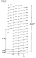
- Fig. 2 shows positions of the nozzle array just before the termination of the printing.
- the paper sheet is transferred upward from below, that is, the print head performs the secondary scanning downward on the paper sheet.
- the main scanning is performed from the left to the right across the paper sheet.
- Symbols P1, P2 and P3 denote positions of the nozzle array upon the first, second and third main scanning passes, respectively.
- Solid line O represents the nozzle used in printing
- broken line O represents the nozzle not used in printing.
- each nozzle is moved to a position one-dot pitch before a position where a one-ahead nozzle was located upon the first main scanning pass P1.
- the second main scanning pass P2 is performed.
- each nozzle is moved to a position one-dot pitch before a position where a one-ahead nozzle was located upon the second main scanning pass P2.
- the third main scanning pass P3 is performed. Thereafter, the interlaced printing with the 20-dot pitch secondary scanning is performed.
- the fully dense lines can be printed by means of the first, second and third main scanning passes P1, P2 and P3, except at a position of the uppermost nozzle #1 upon the first main scanning pass.
- the incomplete print region which would be otherwise caused at the start of the interlaced printing that is, a region having a width of 38/360 inches extending downward from a position of the uppermost nozzle #1 upon the third main scanning pass P3, the dense lines are already printed by the main scanning passes P1, P2 and P3.
- the print head can be set to offset from the upper end of the printing region only by 2/360 inches.
- the incomplete print regions extend over the widths of 38/360 inches from the leading and trailing ends of the paper sheet.
- the adjacent lines are always printed by the different nozzles.
- the adjacent lines are interposed between two lines printed by the same nozzle like #1, #2, #1, #2, #3, #2, #3, ... so that the adjacent lines are not printed by the same nozzles.
- the upper adjacent lines are printed during the subsequent main scanning pass, whether before or after the third main scanning pass P3.
- the quality of the printed image achieved by the main scanning passes P1, P2 and P3 becomes approximately equal to the quality of the printed image achieved by the subsequent interlaced printing.
- the printing was actually performed under the foregoing condition, and the result was that the high-quality print images were achieved both on the region applied with the interlaced printing and the other region such that no distinction therebetween was possible with the naked eyes.
- the same effect can also be achieved at the termination of the printing shown in Fig. 2.
- the print head can be set to offset from the lower end of the printing region only by 2/360 inches.
- the high-quality print image approximate to that given by the interlaced printing can be achieved through the non-interlaced printing during the main scanning passes P1L and P2L.
- nozzles #1 and P2 are used during the interlaced printing, while portions of the nozzles are used during the main scanning passes P1 and P2 at the start of the printing and during the main scanning passes P1L and P2L at the termination of the printing.
- nozzles #2 ⁇ #8 are used during the first main scanning pass P1
- nozzles #1 ⁇ #14 are used during the second main scanning passes P2.
- nozzles #12 ⁇ #19 are used in the last main scanning pass P1L
- only the nozzles #7 ⁇ #20 are used in the before-last main scanning pass P2L.
- Fig. 3 is a flowchart of a control routine to be executed by a microcomputer for achieving the operations shown in Figs. 1 and 2.
- the secondary scanning is referred to as "paper feeding" for facilitating explanation.
- step S6 the paper feeding of 2/360 inches is achieved.
- step S9 an interlaced printing routine is executed. Specifically, the printing is performed during the main scanning pass using all the nozzles #1 ⁇ #20, and then the paper feeding of 20/360 inches is performed. These printing and paper feeding are repeated so as to achieve the interlaced printing.
- a detection signal from the paper sensor 10 (see Fig. 9) is checked every time the paper feeding is achieved.
- the paper sensor 10 is arranged at a position along the paper feeding route from a paper stacker to the print head. If the detection signal from the paper sensor 10 is on, it represents that the paper sheet does not pass over the paper sensor 10. On the other hand, if the detection signal from the paper sensor 10 is off, it represents that the paper sheet passes over the paper sensor 10. Thus, while the signal from the paper sensor 10 is held on at step S10, the interlaced printing routine continues to be executed.
- step S11 a counter for a secondary scanning distance (the number of drive steps of a stepping motor for driving the paper feed roller 11 shown in Fig. 9) F is reset to 0.
- step S12 the interlaced printing routine continues to be executed at step S12.
- the secondary scanning distance F representing an actual paper feeding distance is counted up at every paper feeding (step S13).
- step S14 compares the counted-up secondary scanning distance F with a value (M-2/360 inches), wherein M represents a given paper override distance.
- the paper override distance M represents a paper feeding distance necessary for allowing the paper sheet to move from a point where the trailing end of the paper sheet passes over the paper sensor 10 to a point where the lower end of the printing region of the paper sheet reaches the lowermost nozzle #20 of the print head. This is determined in advance as one of the printer specifications.
- the position of the print head relative to the paper sheet reaches the position of the main scanning pass P3L as shown in Fig. 2, wherein the secondary scanning distance F coincides with the value (M-2/360 inches).
- answer at step S14 becomes negative so that the routine proceeds to step S15 where the counter P is reset to 0.
- step S16 the counter P is incremented by 1 (step S16).
- step S22 the last main scanning pass is performed to achieve the printing using the nozzles #12 ⁇ #19.
- the printed paper sheet is discharged (step S23).
- Fig. 4 shows positions of the nozzle array just after the start of the printing.
- the positions of the nozzle array just before the termination of the printing are not shown in the drawings.
- the figure therefor may be achieved by rotating Fig. 4 by 180 degrees.
- the second preferred embodiment is employed for printing an image with a resolution of 720dpi using the same nozzle array as in the foregoing first preferred embodiment.
- the number n of the nozzles to be driven or used is set to 19.
- a width of the incomplete print region caused at each of the start of the printing and the termination of the printing is 15/360 inches.
- a width of the incomplete print region is known to be 45/360 inches. Accordingly, the widths of the incomplete print regions are largely reduced and thus offset distances of the print head are largely diminished also in this embodiment.
- Fig. 5 shows positions of the nozzle array just after the start of the printing.
- the positions of the nozzle array just before the termination of the printing are not shown in the drawings.
- the figure therefor may be achieved by rotating Fig. 5 by 180 degrees.
- the third preferred embodiment is employed for printing an image with a resolution of 360dpi using the nozzle array with the number n of the driven nozzles being 31.
- a width of the incomplete print region caused at each of the start of the printing and the termination of the printing is 2/360 inches.
- a width of the incomplete print region is known to be 30/360 inches. Accordingly, the widths of the incomplete print regions are largely reduced and thus offset distances of the print head are largely diminished also in this embodiment.
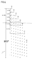
- Fig. 6 shows positions of the nozzle array just after the start of the printing.
- the positions of the nozzle array just before the termination of the printing are not shown in the drawings.
- the figure therefor may be achieved by rotating Fig. 6 by 180 degrees.
- the fourth preferred embodiment is employed for printing an image with a resolution of 720dpi using the same nozzle array as in the foregoing third preferred embodiment.
- the number n of the nozzles to be driven or used is set to 31.
- a width of the incomplete print region caused at each of the start of the printing and the termination of the printing is 6/720 inches.
- a width of the incomplete print region is known to be 90/720 inches. Accordingly, the widths of the incomplete print regions are largely reduced and thus offset distances of the print head are largely diminished also in this embodiment.
- Fig. 7 shows a positional relationship between a print head and a paper sheet in an example of an ink jet printer where the present invention is applied.
- the print head 13 includes N dot forming elements (ink jet nozzles) 51 ⁇ 5n arranged in a secondary scanning direction Y.
- the dot forming elements 51 ⁇ 5n are arranged at a k-dot pitch.
- the paper sheet S is fed in the secondary scanning direction by a unit of an m-dot pitch, and then the subsequent main scanning pass is performed.
- the normal interlaced printing is performed moving the print head in the secondary scanning direction by a unit of an n-dot pitch.
- the foregoing operations moving the print head in the secondary scanning direction by the unit of the m-dot pitch are again repeated at given times. In this fashion, the regions of the paper sheet S to be printed are all covered.
- this printer is connected to an external host computer.
- the printer controls operations of the dot forming elements 51 ⁇ 5n during each main scanning pass of the print head, the number of the dots for the paper feeding in the secondary scanning direction and others. Since the mutual operations between the host computer and the printer are known in the art, no particular explanation thereof is provided herein.
- each nozzle is moved to a position adjacent to the one-ahead nozzle at an upper or lower side thereof.
- the lines are printed in the order which is consistent with the printing order of the lines achieved through the secondary scanning using the secondary scanning distance of n-dot pitch.
Landscapes
- Physics & Mathematics (AREA)
- Engineering & Computer Science (AREA)
- Mathematical Physics (AREA)
- General Engineering & Computer Science (AREA)
- General Physics & Mathematics (AREA)
- Theoretical Computer Science (AREA)
- Ink Jet (AREA)
- Dot-Matrix Printers And Others (AREA)
- Particle Formation And Scattering Control In Inkjet Printers (AREA)
Abstract
Description
- The present invention relates to a serial printer with a print head which performs the raster scanning on a print medium, such as a sheet of paper and a printing method utilizing the raster scanning.
- A print head of a serial printer has a dot forming element array with a number of dot forming elements arranged in a secondary scanning direction, that is, in the direction of movement of a print medium, such as a paper sheet. With this element array, a number of lines can be simultaneously printed on the paper sheet by means of one main scanning pass of the print head across the paper sheet. In the serial printer using such a print head, particularly an ink jet printer, unevenness in characteristic of individual ink jet nozzles or unevenness in pitch between the adjacent ink jet nozzles raises a problem in view of achieving the high-quality print image.
- For solving this problem, United States Patent No. 4,198,642 has proposed a printing method called "interlaced printing" which can provide the high-quality printing by making unobtrusive the unevenness in characteristic or pitch of the ink jet nozzles on a printed image. This interlaced printing employs a nozzle array with N ink jet nozzles arranged in the secondary scanning direction at a pitch corresponding to a k-dot pitch in the print resolution, wherein k is an integer no greater than n which represents the number of the ink jet nozzles to be driven among the N ink jet nozzles, and has no prime factors greater than one in common with n. Every time the nozzle array has achieved one main scanning pass across the paper sheet, the secondary scanning, that is, paper feeding, is performed by a distance corresponding to an n-dot pitch. An example is given hereinbelow.
- In this example, a nozzle array with 20 nozzles (N=n=20) arranged at a pitch corresponding to a 3-dot pitch (k=3) is used for printing an image with a resolution of 360dpi. Expressed in terms of inch, a one-dot pitch is equal to 1/360 inches so that the nozzle pitch, which is the 3-dot pitch, is equal to 3/360 inches, and a paper feeding distance achieved by one-time secondary scanning, that is, a secondary scanning distance, is equal to 20/360 inches.
- Accordingly, if the secondary scanning (paper feeding) is performed once, each nozzle is moved by 20/360 inches so that each nozzle is moved to a position one-dot pitch before a position where a seven-ahead nozzle was located upon the last main scanning, that is, one-dot pitch before 21/360 inches ahead. If the secondary scanning is performed once again, each nozzle is moved to a position two-dot pitch before a position where a fourteen-ahead nozzle was located upon the before-last main scanning. In other words, when a line is printed by means of each of the nozzles during a certain main scanning pass, an upper line adjacent to each printed line is printed, during a subsequent main scanning pass, by means of a nozzle which is seven-nozzles apart from the corresponding nozzle. Similarly, a further upper line adjacent to each of the foregoing upper lines is printed, during a further subsequent main scanning pass, by means of a nozzle which is fourteen-nozzles apart from the foregoing corresponding nozzle.
- In this fashion, in the interlaced printing, the adjacent lines are always printed by the different nozzles. Thus, even if unevenness exists in nozzle characteristic or nozzle pitch, as described before, to some degree, the unevenness is rendered unobtrusive on the printed image so that the high-quality print image can be achieved.
- On the other hand, the foregoing conventional interlaced printing still includes the following problem:
- Specifically, in the conventional interlaced printing, incomplete print regions where lines can not be printed fully densely are caused at leading and trailing ends, in the secondary scanning direction, of the paper sheet. In the foregoing example, a region having a width of 38/360 inches extending downward from a position of the uppermost nozzle of the nozzle array during the first main scanning pass becomes an incomplete print region. Similarly, an incomplete print region having an approximately equal width exists at the trailing end of the paper sheet. These incomplete print regions at the leading and trailing ends of the paper sheet can not be used as printing regions. Thus, in the actual interlaced printing, for causing the leading and trailing incomplete print regions to be outside a printing region of the paper sheet where the printing is to be performed, the print head is set to be positioned so as to offset from upper and lower ends of the printing region of the paper sheet by distances corresponding to widths of the incomplete print regions. However, if the offset magnitudes of the print head relative to the paper sheet are so large, gaps between the print head and the paper sheet become unstable so that the quality of the print image is largely lowered.
- Particularly, in recent years, such printers are widely available on the market, wherein a paper regulating section for regulating a position of a paper sheet upon printing is offset from a position confronting a print head toward a paper outlet side. In the printer thus structured, a distance from the leading end of the paper sheet to the upper end of the printing region and a distance from the lower end of the printing region to the trailing end of the paper sheet become greater as compared with the case where the paper regulating section is arranged at the position confronting the print head. Thus, the regions are enlarged where the foregoing gaps are unstable. On the other hand, although it has been attempted to increase the number of the nozzles arranged in the nozzle array for enhancing the printing efficiency, this increases the foregoing offset magnitudes of the print head relative to the paper sheet and narrows the high-quality printing region.
- As one method for diminishing the offset magnitudes of the print head, it may be considered to employ the normal printing method, instead of the interlaced printing method, in the foregoing incomplete print regions so as to print the lines densely. As appreciated, in the normal printing method, the secondary scanning is performed by the one-dot pitch every time the main scanning is finished, However, according to this method, the print image quality of the region where the normal printing method is applied is largely deteriorated as compared with the print image quality of the region where the interlaced printing method is applied, and thus the boundary therebetween becomes remarkable. This is because, since the adjacent lines corresponding in number to the foregoing integer k are printed by the same nozzles in the normal printing method, the unevenness in nozzle characteristic or nozzle pitch appears clearly on the printed image.
- Therefore, it is an object of the present invention to provide an improved serial printer. And it is another object of the present invention to provide an improved printing method utilizing the interlaced printing.
- According to one aspect of the present invention, a serial printer comprises a print head having N dot forming elements arranged in a secondary scanning direction, N being an integer; main scanning control means for operating the dot forming elements to print on a print medium while performing main scanning across the print medium using the print head; and secondary scanning control means for performing secondary scanning on the print medium after the main scanning, wherein, given that a pitch of the dot forming elements is k times a dot pitch in print resolution and that k is an integer which is no greater than n and has no prime factors greater than one in common with n, n being an integer no greater than N and representing the number of the dot forming elements to be driven, the secondary scanning control means performs the secondary scanning at least once at each of the start of the printing and the termination of the printing using a first secondary scanning distance which is m times the dot pitch and performs the secondary scanning other than the at least once secondary scanning using a second secondary scanning distance which is n times the dot pitch, m being an integer which is less than n and has no prime factors greater than one in common with k.
- According to another aspect of the present invention, a printing method comprises the steps of: (A) arranging N dot forming elements in a secondary scanning direction, N being an integer, a pitch of the dot forming elements being k times a dot pitch in print resolution; (B) performing a main scanning for moving the dot forming elements in a main scanning direction; (C) driving the dot forming elements for forming a number of dots at the step (B); (D) performing a first secondary scanning for moving the dot forming elements in a secondary scanning direction at least once at each of the start of the printing and the termination of the printing, and using a first secondary scanning distance which is m times the dot pitch, m being an integer which is less than n and has no prime factors greater than one in common with k, wherein n is an integer no greater than N and represents the number of the dot forming elements to be driven, and k is an integer which is no greater than n and has no prime factors greater than one in common with n; and (E) performing a second secondary scanning for moving the dot forming elements in a secondary scanning direction and using a second secondary scanning distance which is n times the dot pitch; (F) repeating the steps (B), (C) and (E).
- The present invention will be understood more fully from the detailed description given hereinbelow, taken in conjunction with the accompanying drawings.
- In the drawings:
- Fig. 1 is an explanatory diagram showing nozzle positions just after the start of printing according to a first preferred embodiment of the present invention;
- Fig. 2 is an explanatory diagram showing nozzle positions just before the termination of printing according to the first preferred embodiment;
- Fig. 3 is a flowchart of a control routine to be executed by a microcomputer according to the first preferred embodiment;
- Fig. 4 is an explanatory diagram showing nozzle positions just after the start of printing according to a second preferred embodiment of the present invention;
- Fig. 5 is an explanatory diagram showing nozzle positions just after the start of printing according to a third preferred embodiment of the present invention;
- Fig. 6 is an explanatory diagram showing nozzle positions just after the start of printing according to a fourth preferred embodiment of the present invention;
- Fig. 7 is an explanatory diagram showing a positional relationship between a print head and a paper sheet in an ink jet printer where the present invention is applied;
- Fig. 8 is an explanatory diagram showing nozzle positions just after the start of printing according to the related art;
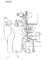
- Fig. 9 is a partial sectional view showing a printing mechanism of a printer where the present invention is applied;
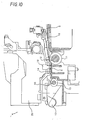
- Fig. 10 is a partial sectional view showing a state of the printing mechanism during printing; and
- Fig. 11 is a partial sectional view showing a state of the printing mechanism upon termination of the printing.
- Prior to description of preferred embodiments, relationship between the printing mechanism and the transfer state of a paper sheet in a printer where the present invention is applied, will be described hereinbelow with reference to Figs. 9 to 11.
- In Fig. 9, a paper sheet S is transferred from a paper inlet at the right in the figure toward the left in the figure. When the paper sheet S passes a
paper sensor 10, a drive control section (not shown) detects the change of thepaper sensor 10 from off to on and drives apaper feed roller 11 and afollower roller 12. Thus, the paper sheet S is transferred toward aprint head 13. Theprint head 13 has a nozzle array arranged with, for example, 64 dot forming elements, such as 64 ink jet nozzles (#1~#64). At a position confronting theprint head 13 is arranged apaper regulating section 14 for regulating a position of the paper sheet S upon printing. The paper regulatingsection 14 has a planar surface parallel to a head surface of theprint head 13 and an inclined surface at the side of the paper inlet. The planar surface of thesection 14 is oriented toward the head surface of theprint head 13 other than a portion of the head surface where the nozzle array is mounted. Numeral 20 in the figure denotes a carriage for moving theprint head 13 during the main scanning. - With this arrangement, the leading end, in the secondary scanning direction, of the paper sheet S transferred between the
paper feed roller 11 and thefollower roller 12 reaches the inclined surface of thepaper regulating section 14 at a given angle. Thereafter, the leading end of the paper sheet S reaches the parallel surface of thepaper regulating section 14, guided by the inclined surface thereof. Fig. 10 shows this state. In the state shown in Fig. 10, the paper sheet S is parallel to theprint head 13, and thus gaps between a print surface of the paper sheet S and theprint head 13 become stable to make possible the high-quality printing. The paper sheet S on the parallel surface of thepaper regulating section 14 is, while applied with the interlaced printing, held between apaper discharge roller 15 and anotched roller 16 in sequence from the leading end to the trailing end thereof, and further guided toward a paper outlet via an auxiliary paper discharge notchedmember 17. Then, when the printing on the paper sheet S is further advanced, the trailing end of the paper sheet S is released from between thepaper feed roller 11 and thefollower roller 12. Fig. 11 shows this state. - Now, a first preferred embodiment of the present invention will be described hereinbelow.
- Fig. 1 shows positions of the nozzle array just after the start of the printing, while Fig. 2 shows positions of the nozzle array just before the termination of the printing. In the figures, the paper sheet is transferred upward from below, that is, the print head performs the secondary scanning downward on the paper sheet. The main scanning is performed from the left to the right across the paper sheet. Symbols P1, P2 and P3 denote positions of the nozzle array upon the first, second and third main scanning passes, respectively. Solid line O represents the nozzle used in printing, while broken line O represents the nozzle not used in printing.
- The first preferred embodiment aims to fully print the foregoing incomplete print regions in the interlaced printing under the same condition as that of the foregoing conventional example. Accordingly, the print resolution is set to 360dpi, the number of nozzles n (=N) to 20, and the nozzle pitch to the 3-dot pitch (k=3) (=3/360 inches). Further, an integer j is set to "1".
- In this embodiment, two kinds of values are set for paper feeding distances, that is, distances of the secondary scanning. The first secondary scanning distance is set to an m-dot pitch (m=k-j=k-1=2) (=2/360 inches), as shown in Fig. 1 between P1 and P2 and between P2 and P3 and as shown in Fig. 2 between P3L (the main scanning pass before the before-last main scanning pass) and P2L (the before-last main scanning pass) and between P2L and P1L (the last main scanning pass).
- The second secondary scanning distance is set to an n-dot pitch (n=20) (=20/360 inches) between P3 to P3L, and thus equal to the secondary scanning distance according to the foregoing conventional interlaced printing method.
- As shown in Fig. 1, when the first 2-dot pitch secondary scanning is performed after the first main scanning pass P1, each nozzle is moved to a position one-dot pitch before a position where a one-ahead nozzle was located upon the first main scanning pass P1. At this position, the second main scanning pass P2 is performed. Subsequently, when the second 2-dot pitch secondary scanning is performed, each nozzle is moved to a position one-dot pitch before a position where a one-ahead nozzle was located upon the second main scanning pass P2. At this position, the third main scanning pass P3 is performed. Thereafter, the interlaced printing with the 20-dot pitch secondary scanning is performed.
- According to the foregoing operation, the fully dense lines can be printed by means of the first, second and third main scanning passes P1, P2 and P3, except at a position of the
uppermost nozzle # 1 upon the first main scanning pass. In the incomplete print region which would be otherwise caused at the start of the interlaced printing, that is, a region having a width of 38/360 inches extending downward from a position of theuppermost nozzle # 1 upon the third main scanning pass P3, the dense lines are already printed by the main scanning passes P1, P2 and P3. - As a result, only the region having a width of 2/360 inches extending downward from the position of the
uppermost nozzle # 1 upon the first main scanning pass P1 becomes a region where the fully dense printing is not possible. Accordingly, at the start of the printing, the print head can be set to offset from the upper end of the printing region only by 2/360 inches. On the other hand, as shown in Fig. 8 and as described before, in the conventional interlaced printing, the incomplete print regions extend over the widths of 38/360 inches from the leading and trailing ends of the paper sheet. Thus, the advantageous effect is significant in this embodiment. - Further, as seen from Fig. 1, in the lines printed during the first, second and third main scanning passes P1, P2 and P3, the adjacent lines are always printed by the different nozzles. For example, observing the nozzle numbers in order from the uppermost line in the printing region, between two lines printed by the same nozzle is interposed a line printed by the different nozzle like #1, #2, #1, #2, #3, #2, #3, ... so that the adjacent lines are not printed by the same nozzles.
- Further, observing the order of the lines printed, relative to the lines printed during the last main scanning pass, the upper adjacent lines are printed during the subsequent main scanning pass, whether before or after the third main scanning pass P3.
- As appreciated, in this embodiment, the quality of the printed image achieved by the main scanning passes P1, P2 and P3 becomes approximately equal to the quality of the printed image achieved by the subsequent interlaced printing. The printing was actually performed under the foregoing condition, and the result was that the high-quality print images were achieved both on the region applied with the interlaced printing and the other region such that no distinction therebetween was possible with the naked eyes.
- The same effect can also be achieved at the termination of the printing shown in Fig. 2. Specifically, since the incomplete print region at the termination of the printing is only a region having a width of 2/360 inches from a position of the
lowermost nozzle # 20 upon the final main scanning pass P1L, the print head can be set to offset from the lower end of the printing region only by 2/360 inches. Further, the high-quality print image approximate to that given by the interlaced printing can be achieved through the non-interlaced printing during the main scanning passes P1L and P2L. - As shown in Figs. 1 and 2, all the 20 nozzles are used during the interlaced printing, while portions of the nozzles are used during the main scanning passes P1 and P2 at the start of the printing and during the main scanning passes P1L and P2L at the termination of the printing. For example, only the
nozzles # 2~#8 are used during the first main scanning pass P1, and only thenozzles # 1~#14 are used during the second main scanning passes P2. Similarly, only thenozzles # 12~#19 are used in the last main scanning pass P1L, and only thenozzles # 7~#20 are used in the before-last main scanning pass P2L. The reason for this is that only those lines which can not be printed by the interlaced printing are set to be printed by the foregoing main scanning passes in an interpolating fashion while the those lines which can be printed by the interlaced printing are set to be printed by the interlaced printing. It is important to use the interlaced printing as much as possible for achieving the high-quality print image. - Fig. 3 is a flowchart of a control routine to be executed by a microcomputer for achieving the operations shown in Figs. 1 and 2. In this flowchart, the secondary scanning is referred to as "paper feeding" for facilitating explanation.
- At step S1, a sheet of paper is fed so that the uppermost nozzle of the print head is located at a
position 2/360 inches from the upper end of the printing region. Then, a counter for the number P of the main scanning passes is reset to 0 (step S2), and the counter is incremented by "1" (step S3). Subsequently, the number P is checked whether P=1 (step S4). If P=1 representing the first main scanning pass, the routine proceeds to step S5 where the first main scanning pass is performed to achieve the printing using thenozzles # 2~#8. Then, at step S6, the paper feeding of 2/360 inches is achieved. - The routine now returns to step S3 where the counter is incremented by "1". Since answer at step S4 becomes negative at this time, the routine proceeds to step S7 where it is checked whether P=2. If P=2 representing the second main scanning pass, the routine proceeds to step S8 where the second main scanning pass is performed to achieve the printing using the
nozzles # 1~#14. Then, at step S6, the paper feeding of 2/360 inches is achieved. - The routine again returns to step S3 where the counter is incremented by "1", and now proceeds to step S9 via negative answers at steps S4 and S7. At step S9, an interlaced printing routine is executed. Specifically, the printing is performed during the main scanning pass using all the
nozzles # 1~#20, and then the paper feeding of 20/360 inches is performed. These printing and paper feeding are repeated so as to achieve the interlaced printing. - During the execution of the interlaced printing routine, a detection signal from the paper sensor 10 (see Fig. 9) is checked every time the paper feeding is achieved. The
paper sensor 10 is arranged at a position along the paper feeding route from a paper stacker to the print head. If the detection signal from thepaper sensor 10 is on, it represents that the paper sheet does not pass over thepaper sensor 10. On the other hand, if the detection signal from thepaper sensor 10 is off, it represents that the paper sheet passes over thepaper sensor 10. Thus, while the signal from thepaper sensor 10 is held on at step S10, the interlaced printing routine continues to be executed. - On the other hand, if the signal from the
paper sensor 10 is switched from on to off, the routine proceeds to step S11 where a counter for a secondary scanning distance (the number of drive steps of a stepping motor for driving thepaper feed roller 11 shown in Fig. 9) F is reset to 0. Then, the interlaced printing routine continues to be executed at step S12. In the interlaced printing routine at step S12, the secondary scanning distance F representing an actual paper feeding distance is counted up at every paper feeding (step S13). Subsequently, step S14 compares the counted-up secondary scanning distance F with a value (M-2/360 inches), wherein M represents a given paper override distance. The paper override distance M represents a paper feeding distance necessary for allowing the paper sheet to move from a point where the trailing end of the paper sheet passes over thepaper sensor 10 to a point where the lower end of the printing region of the paper sheet reaches thelowermost nozzle # 20 of the print head. This is determined in advance as one of the printer specifications. When the interlaced printing routine at step S12 is repeated, the position of the print head relative to the paper sheet reaches the position of the main scanning pass P3L as shown in Fig. 2, wherein the secondary scanning distance F coincides with the value (M-2/360 inches). Thus, answer at step S14 becomes negative so that the routine proceeds to step S15 where the counter P is reset to 0. - Subsequently, the counter P is incremented by 1 (step S16). Then, step S17 checks whether P=1. Since P=1 at this time representing the main scanning pass P3L which is before the before-last main scanning pass P2L, the routine proceeds to step S18 where the main scanning pass P3L is performed to achieve the printing using all the
nozzles # 1~#20. Subsequently, the paper feeding is achieved by 2/360 inches (step S19). - The routine now returns to step S16 where the counter P is incremented by "1". Since answer at step S17 becomes negative at this time, the routine proceeds to step S20 where it is checked whether P=2. Since P=2 at this time representing the before-last main scanning pass P2L, the routine proceeds to step S21 where the before-last main scanning pass is performed to achieve the printing using the
nozzles # 7~#20. Then, at step S19, the paper feeding of 2/360 inches is achieved. - The routine again returns to step S16 where the counter is incremented by "1", and now proceeds to step S22 via negative answers at steps S17 and S20 representing the last main scanning pass P1L. At step S22, the last main scanning pass is performed to achieve the printing using the
nozzles # 12~#19. - When the printing on one paper sheet is finished, the printed paper sheet is discharged (step S23).
- Now, a second preferred embodiment of the present invention will be described hereinbelow.
- Fig. 4 shows positions of the nozzle array just after the start of the printing. The positions of the nozzle array just before the termination of the printing are not shown in the drawings. As obvious from the relationship between Figs. 1 and 2, the figure therefor may be achieved by rotating Fig. 4 by 180 degrees.
- The second preferred embodiment is employed for printing an image with a resolution of 720dpi using the same nozzle array as in the foregoing first preferred embodiment.
- In this embodiment, the number n of the nozzles to be driven or used is set to 19. A nozzle pitch is set to a 6-dot pitch (k=6) (=6/720=3/360 inches). A secondary scanning distance is set to a 7-dot pitch (m=k+j=k+l=7) (=7/720 inches) for the five-times secondary scanning performed at each of the start of the printing and the termination of the printing. For the secondary scanning other than the foregoing five-times secondary scanning, a secondary scanning distance is set to a 19-dot pitch (n=19) (=19/720 inches), which is for the interlaced printing.
- As seen from Fig. 4, a width of the incomplete print region caused at each of the start of the printing and the termination of the printing is 15/360 inches. On the other hand, although not shown in the drawings, if only the interlaced printing is performed under the same condition, a width of the incomplete print region is known to be 45/360 inches. Accordingly, the widths of the incomplete print regions are largely reduced and thus offset distances of the print head are largely diminished also in this embodiment.
- As appreciated, this embodiment further achieves advantageous effects as those achieved in the foregoing first preferred embodiment.
- Now, a third preferred embodiment of the present invention will be described hereinbelow.
- Fig. 5 shows positions of the nozzle array just after the start of the printing. The positions of the nozzle array just before the termination of the printing are not shown in the drawings. As obvious from the relationship between Figs. 1 and 2, the figure therefor may be achieved by rotating Fig. 5 by 180 degrees.
- The third preferred embodiment is employed for printing an image with a resolution of 360dpi using the nozzle array with the number n of the driven nozzles being 31.
- In this embodiment, a nozzle pitch is set to a 2-dot pitch (k=2) (=2/360 inches). A secondary scanning distance is set to a 3-dot pitch (m=k+j=k+1=3) (=3/360 inches) for the first and last secondary scanning. For the secondary scanning other than the foregoing first and last secondary scanning, a secondary scanning distance is set to a 31-dot pitch (n=31) (=31/360 inches), which is for the interlaced printing.
- As seen from Fig. 5, a width of the incomplete print region caused at each of the start of the printing and the termination of the printing is 2/360 inches. On the other hand, although not shown in the drawings, if only the interlaced printing is performed under the same condition, a width of the incomplete print region is known to be 30/360 inches. Accordingly, the widths of the incomplete print regions are largely reduced and thus offset distances of the print head are largely diminished also in this embodiment.
- As appreciated, this embodiment further achieves advantageous effects as those achieved in the foregoing first preferred embodiment.
- Now, a fourth preferred embodiment of the present invention will be described hereinbelow.
- Fig. 6 shows positions of the nozzle array just after the start of the printing. The positions of the nozzle array just before the termination of the printing are not shown in the drawings. As obvious from the relationship between Figs. 1 and 2, the figure therefor may be achieved by rotating Fig. 6 by 180 degrees.
- The fourth preferred embodiment is employed for printing an image with a resolution of 720dpi using the same nozzle array as in the foregoing third preferred embodiment.
- In this embodiment, the number n of the nozzles to be driven or used is set to 31. A nozzle pitch is set to a 4-dot pitch (k=4) (=4/720 inches). A secondary scanning distance is set to a 3-dot pitch (m=k-j=k-1=3) (=3/720 inches) for the two-times secondary scanning performed at each of the start of the printing and the termination of the printing. For the secondary scanning other than the foregoing two-times secondary scanning, a secondary scanning distance is set to a 31-dot pitch (n=31) (=31/720 inches), which is for the interlaced printing.
- As seen from Fig. 6, a width of the incomplete print region caused at each of the start of the printing and the termination of the printing is 6/720 inches. On the other hand, although not shown in the drawings, if only the interlaced printing is performed under the same condition, a width of the incomplete print region is known to be 90/720 inches. Accordingly, the widths of the incomplete print regions are largely reduced and thus offset distances of the print head are largely diminished also in this embodiment.
- As appreciated, this embodiment further achieves advantageous effects as those achieved in the foregoing first preferred embodiment.
- Fig. 7 shows a positional relationship between a print head and a paper sheet in an example of an ink jet printer where the present invention is applied.
- In Fig. 7, the
print head 13 includes N dot forming elements (ink jet nozzles) 51~5n arranged in a secondary scanning direction Y. Thedot forming elements 51~5n are arranged at a k-dot pitch. Theprint head 13, while moving in a main scanning direction X relative to the paper sheet S, prints dot patterns on a rectangular region of the paper sheet S where thedot forming elements 51~5n cover. When one main scanning pass is achieved, the paper sheet S is fed in the secondary scanning direction by a unit of an m-dot pitch, and then the subsequent main scanning pass is performed. After the operations are repeated given times, the normal interlaced printing is performed moving the print head in the secondary scanning direction by a unit of an n-dot pitch. Then, finally, the foregoing operations moving the print head in the secondary scanning direction by the unit of the m-dot pitch are again repeated at given times. In this fashion, the regions of the paper sheet S to be printed are all covered. - Although not shown in the drawings, this printer is connected to an external host computer. In response to data and commands inputted from the host computer, the printer controls operations of the
dot forming elements 51~5n during each main scanning pass of the print head, the number of the dots for the paper feeding in the secondary scanning direction and others. Since the mutual operations between the host computer and the printer are known in the art, no particular explanation thereof is provided herein. - In the foregoing preferred embodiments, the integer j is set to 1, that is, m=k±1. On the other hand, the integer j may take another value other than 1 as long as m=k±j is less than n and has no prime factors greater than one in common with n.
- Further, as appreciated, if m is set to k-j or k+j, once the secondary scanning is performed with the secondary scanning distance of m-dot pitch, each nozzle is moved to a position adjacent to the one-ahead nozzle at an upper or lower side thereof. This means that, as the number of times of the main scanning increases, the adjacent lines are printed in a given order. Specifically, when m=k-j, a line adjacent to the last-printed line is next printed at the upper side of the last-printed line, while, when m=k+j, a line adjacent to the last-printed line is next printed at the lower side of the last-printed line. Accordingly, by selecting one of m=k-j and m=k+j as in the foregoing preferred embodiments, the lines are printed in the order which is consistent with the printing order of the lines achieved through the secondary scanning using the secondary scanning distance of n-dot pitch.
- While the present invention has been described in terms of the preferred embodiments, the invention is not limited thereto, but can be embodied in various ways without departing from the principle of the invention as defined in the appended claims.
- The aforegoing description has been given by way of example only and it will be appreciated by a person skilled in the art that modifications can be made without departing from the scope of the present invention.
Claims (10)
- A serial printer comprising:a print head (13) having N dot forming elements (51 - 5n) arranged in a secondary scanning direction, N being an integer;main scanning control means for operating said dot forming elements to print on a print medium while performing main scanning across the print medium using said print head; andsecondary scanning control means for performing secondary scanning on the print medium after said main scanning, and characterised in that,given that a pitch of said dot forming elements is k times a dot pitch in print resolution and that k is an integer which is no greater than n and has no prime factors greater than one in common with n, n being an integer no greater than N and representing the number of the dot forming elements to be driven, said secondary scanning control means performs the secondary scanning at least once at each of the start of the printing and the termination of the printing using a first secondary scanning distance which is m times said dot pitch and performs the secondary scanning other than said at least once secondary scanning using a second secondary scanning distance which is n times said dot pitch, m being an integer which is less than n and has no prime factors greater than one in common with k.
- The serial printer according to claim 1, wherein, given that j is an integer no less than one and less than n, m has no prime factors greater than one in common with n and is selected to one of k-j and k+j.
- The serial printer according to claim 2, wherein said one of k-j and k+j is selected so as to print lines through the secondary scanning using the first secondary scanning distance in an order which is consistent with a printing order of lines achieved through the secondary scanning using said second scanning distance.
- The serial printer according to any preceding claim, wherein said main scanning control means drives all the dot forming elements during the main scanning before or after the secondary scanning using said second secondary scanning distance, while said main scanning control means drives only those dot forming elements corresponding to lines which are unable to be printed during said main scanning before or after the secondary scanning using said second secondary scanning distance, during the other main scanning.
- The serial printer according to any one of claims 1 to 3, wherein said main scanning control means drives all the dot forming elements during the main scanning before or after the secondary scanning using said second secondary scanning distance, while said main scanning control drives only those dot forming elements corresponding to lines which are unable to be printed thereby during the main scanning before or after the secondary scanning using said first secondary scanning distance.
- A printing method comprising the steps of:(A) arranging N dot forming elements (51 - 5n) in a secondary scanning direction (Y), N being an integer, a pitch of the dot forming elements being k times a dot pitch in print resolution;(B) performing a main scanning for moving the dot forming elements in a main scanning direction (x);(C) driving the dot forming elements for forming a number of dots at the step (B); characterised by further comprising the steps of;(D) performing a first secondary scanning for moving the dot forming elements in a secondary scanning direction at least once at each of the start of the printing and the termination of the printing, and using a first secondary scanning distance which is m times the dot pitch, m being an integer which is less than n and has no prime factors greater than one in common with k, wherein n is an integer no greater than N and represents the number of the dot forming elements to be driven, and k is an integer which is no greater than n and has no prime factors greater than one in common with n; and(E) performing a second secondary scanning for moving the dot forming elements in a secondary scanning direction and using a second secondary scanning distance which is n times the dot pitch;(F) repeating the steps (B), (C) and (E).
- The printing method according to claim 6, wherein, given that j is an integer no less than one and less than n, m has no prime factors greater than one in common with n and is selected to be one of k-j and k+j.
- The printing method according to claim 7, wherein the one of k-j and k+j is selected so as to print lines in step (D) in an order which is consistent with a printing order of lines achieved in the steps (B), (C) and (E).
- The printing method according to any one of claims 6 to 8, wherein all the dot forming elements are driven during the step (B) before or after the step (E), while only those dot forming elements corresponding to lines which are unable to be printed during the step (B) in which all the dot forming elements are driven, are driven during the other step (B).
- The printing method according to claim 9, wherein said other step (B) is the step (B) before or after the step (D).
Applications Claiming Priority (6)
| Application Number | Priority Date | Filing Date | Title |
|---|---|---|---|
| JP166562/95 | 1995-06-30 | ||
| JP16656295 | 1995-06-30 | ||
| JP16656295 | 1995-06-30 | ||
| JP13043396A JP3284883B2 (en) | 1995-06-30 | 1996-05-24 | Printing method of serial printer |
| JP13043396 | 1996-05-24 | ||
| JP130433/96 | 1996-05-24 |
Publications (3)
| Publication Number | Publication Date |
|---|---|
| EP0751476A2 true EP0751476A2 (en) | 1997-01-02 |
| EP0751476A3 EP0751476A3 (en) | 1999-04-07 |
| EP0751476B1 EP0751476B1 (en) | 2002-10-02 |
Family
ID=26465568
Family Applications (1)
| Application Number | Title | Priority Date | Filing Date |
|---|---|---|---|
| EP96304847A Expired - Lifetime EP0751476B1 (en) | 1995-06-30 | 1996-07-01 | Serial printer and printing method |
Country Status (4)
| Country | Link |
|---|---|
| US (1) | US5874970A (en) |
| EP (1) | EP0751476B1 (en) |
| JP (1) | JP3284883B2 (en) |
| DE (1) | DE69624044T2 (en) |
Cited By (7)
| Publication number | Priority date | Publication date | Assignee | Title |
|---|---|---|---|---|
| EP0876920A2 (en) * | 1997-05-07 | 1998-11-11 | Seiko Epson Corporation | Dot printing with partial double scanning of raster lines |
| EP0927633A1 (en) * | 1997-05-20 | 1999-07-07 | Seiko Epson Corporation | Printer and printing therefor |
| EP0931669A3 (en) * | 1998-01-23 | 2000-02-02 | Seiko Epson Corporation | Printer, method of printing, and recording medium to actualize the printer |
| EP0879705A3 (en) * | 1997-05-20 | 2000-03-15 | Seiko Epson Corporation | Printing system, method of printing and recording medium to realize the method |
| US6099105A (en) * | 1996-07-18 | 2000-08-08 | Seiko Epson Corporation | Printing system and method for recording images using multivaluing techniques |
| EP1043166A2 (en) * | 1999-04-06 | 2000-10-11 | Seiko Epson Corporation | Ink-jet recording apparatus and method |
| EP1769930A1 (en) * | 2005-09-30 | 2007-04-04 | Brother Kogyo Kabushiki Kaisha | Image-forming device |
Families Citing this family (3)
| Publication number | Priority date | Publication date | Assignee | Title |
|---|---|---|---|---|
| JPH10329347A (en) * | 1997-05-30 | 1998-12-15 | Mitsubishi Electric Corp | Serial thermal recorder |
| JP4345046B2 (en) | 1999-12-06 | 2009-10-14 | 富士フイルム株式会社 | Inkjet printer and image recording method |
| JP2002283543A (en) * | 2001-03-22 | 2002-10-03 | Konica Corp | Ink jet recording device |
Citations (4)
| Publication number | Priority date | Publication date | Assignee | Title |
|---|---|---|---|---|
| US4198642A (en) * | 1978-01-09 | 1980-04-15 | The Mead Corporation | Ink jet printer having interlaced print scheme |
| US4712185A (en) * | 1984-04-28 | 1987-12-08 | Kabushiki Kaisha Toshiba | Dot interpolation control system |
| EP0526186A2 (en) * | 1991-08-02 | 1993-02-03 | Canon Kabushiki Kaisha | Ink jet recording method |
| EP0559370A2 (en) * | 1992-02-26 | 1993-09-08 | Canon Kabushiki Kaisha | Method for recording image and apparatus therefor and recorded material by such an apparatus |
-
1996
- 1996-05-24 JP JP13043396A patent/JP3284883B2/en not_active Expired - Lifetime
- 1996-06-28 US US08/671,643 patent/US5874970A/en not_active Expired - Lifetime
- 1996-07-01 DE DE69624044T patent/DE69624044T2/en not_active Expired - Lifetime
- 1996-07-01 EP EP96304847A patent/EP0751476B1/en not_active Expired - Lifetime
Patent Citations (4)
| Publication number | Priority date | Publication date | Assignee | Title |
|---|---|---|---|---|
| US4198642A (en) * | 1978-01-09 | 1980-04-15 | The Mead Corporation | Ink jet printer having interlaced print scheme |
| US4712185A (en) * | 1984-04-28 | 1987-12-08 | Kabushiki Kaisha Toshiba | Dot interpolation control system |
| EP0526186A2 (en) * | 1991-08-02 | 1993-02-03 | Canon Kabushiki Kaisha | Ink jet recording method |
| EP0559370A2 (en) * | 1992-02-26 | 1993-09-08 | Canon Kabushiki Kaisha | Method for recording image and apparatus therefor and recorded material by such an apparatus |
Cited By (27)
| Publication number | Priority date | Publication date | Assignee | Title |
|---|---|---|---|---|
| US6099105A (en) * | 1996-07-18 | 2000-08-08 | Seiko Epson Corporation | Printing system and method for recording images using multivaluing techniques |
| EP0876920A3 (en) * | 1997-05-07 | 1999-12-29 | Seiko Epson Corporation | Dot printing with partial double scanning of raster lines |
| EP0876920A2 (en) * | 1997-05-07 | 1998-11-11 | Seiko Epson Corporation | Dot printing with partial double scanning of raster lines |
| US6190001B1 (en) | 1997-05-07 | 2001-02-20 | Seiko Epson Corporation | Dot printing with partial double scanning of raster lines |
| EP0927633A4 (en) * | 1997-05-20 | 2002-05-02 | Seiko Epson Corp | Printer and printing therefor |
| EP0927633A1 (en) * | 1997-05-20 | 1999-07-07 | Seiko Epson Corporation | Printer and printing therefor |
| EP0879705A3 (en) * | 1997-05-20 | 2000-03-15 | Seiko Epson Corporation | Printing system, method of printing and recording medium to realize the method |
| US6170932B1 (en) | 1997-05-20 | 2001-01-09 | Seiko Epson Corporation | Printing system, method of printing, and recording medium to realize the method |
| EP0931669A3 (en) * | 1998-01-23 | 2000-02-02 | Seiko Epson Corporation | Printer, method of printing, and recording medium to actualize the printer |
| US6250734B1 (en) | 1998-01-23 | 2001-06-26 | Seiko Epson Corporation | Method and apparatus for printing with different sheet feeding amounts and accuracies |
| US6964466B1 (en) | 1999-04-06 | 2005-11-15 | Seiko Epson Corporation | Ink-jet recording apparatus and recording method thereof |
| US7669999B2 (en) | 1999-04-06 | 2010-03-02 | Seiko Epson Corporation | Ink-jet recording apparatus and recording method therefor |
| EP1043166A2 (en) * | 1999-04-06 | 2000-10-11 | Seiko Epson Corporation | Ink-jet recording apparatus and method |
| US7077499B2 (en) | 1999-04-06 | 2006-07-18 | Seiko Epson Corporation | Ink-jet recording apparatus and recording method therefor |
| US8277042B2 (en) | 1999-04-06 | 2012-10-02 | Seiko Epson Corporation | Ink-jet recording apparatus and recording method therefor |
| US7255434B2 (en) | 1999-04-06 | 2007-08-14 | Seiko Epson Corporation | Sheet feeding device and ink-jet recording apparatus incorporating the same |
| US7296886B2 (en) | 1999-04-06 | 2007-11-20 | Seiko Epson Corporation | Ink-jet recording apparatus and recording method therefor |
| US7377633B2 (en) | 1999-04-06 | 2008-05-27 | Seiko Epson Corporation | Ink-jet recording apparatus and recording method therefor |
| US7401916B2 (en) | 1999-04-06 | 2008-07-22 | Seiko Epson Corporation | Ink-jet recording apparatus and recording method therefor |
| EP1043166A3 (en) * | 1999-04-06 | 2002-04-24 | Seiko Epson Corporation | Ink-jet recording apparatus and method |
| US7854503B2 (en) | 1999-04-06 | 2010-12-21 | Seiko Epson Corporation | Ink-jet recording apparatus and recording method therefor |
| US8267512B2 (en) | 1999-04-06 | 2012-09-18 | Seiko Epson Corporation | Ink-jet recording apparatus and recording method therefor |
| US7901066B2 (en) | 1999-04-06 | 2011-03-08 | Seiko Epson Corporation | Ink-jet recording apparatus and recording method therefor |
| US8029128B2 (en) | 1999-04-06 | 2011-10-04 | Seiko Epson Corporation | Ink-jet recording apparatus and recording method therefor |
| US8109628B2 (en) | 1999-04-06 | 2012-02-07 | Seiko Epson Corporation | Ink-jet recording apparatus and recording method therefor |
| US7883202B2 (en) | 2005-09-30 | 2011-02-08 | Brother Kogyo Kabushiki Kaisha | Image-forming device |
| EP1769930A1 (en) * | 2005-09-30 | 2007-04-04 | Brother Kogyo Kabushiki Kaisha | Image-forming device |
Also Published As
| Publication number | Publication date |
|---|---|
| EP0751476A3 (en) | 1999-04-07 |
| JPH0971009A (en) | 1997-03-18 |
| JP3284883B2 (en) | 2002-05-20 |
| DE69624044T2 (en) | 2003-06-05 |
| EP0751476B1 (en) | 2002-10-02 |
| DE69624044D1 (en) | 2002-11-07 |
| US5874970A (en) | 1999-02-23 |
Similar Documents
| Publication | Publication Date | Title |
|---|---|---|
| EP0730246B1 (en) | Method of transitioning between ink jet printing modes | |
| US6848765B1 (en) | End-of-page advance-distance decrease, in liquid-ink printers | |
| EP1555134B1 (en) | Print media edge printing | |
| EP0720914B1 (en) | Optimizing printing speed in an ink jet printer | |
| US6375307B1 (en) | Printing apparatus and method | |
| EP0595650A2 (en) | Colour ink jet recording method and apparatus | |
| EP0931669B1 (en) | Printer, method of printing, and recording medium to actualize the printer | |
| US6027203A (en) | Page wide ink-jet printer and method of making | |
| JP4143657B2 (en) | Marking device | |
| EP0751476B1 (en) | Serial printer and printing method | |
| JPH1034935A (en) | Dot adhesion control method of liquid ink printer | |
| EP1192048B1 (en) | Method of printing with an ink jet printer using multiple carriage speeds | |
| JPH10157172A (en) | Edge enhancement depletion method related to excessive ink drop for attainment of high-resolution x/y axis address assigning performance in ink-jet print | |
| US6912063B1 (en) | Ink jet recording apparatus | |
| US6158835A (en) | Nozzle usage balancing for ink-jet printers | |
| US6357856B1 (en) | Printing with a vertical nozzle array head | |
| US5603578A (en) | Serial printer and printing method therefor | |
| JP4632416B2 (en) | Inkjet recording apparatus and inkjet recording method | |
| JP4194226B2 (en) | Ink jet recording apparatus and image data correction method | |
| JP3533771B2 (en) | Printer for color and monochrome printing | |
| US6863372B2 (en) | Printer device and method | |
| JP4133014B2 (en) | Printing pattern printing method for transport deviation detection | |
| US20050140708A1 (en) | Printer device and method | |
| EP1029686B1 (en) | Printing apparatus and method | |
| JP2613205B2 (en) | Dot matrix recording method |
Legal Events
| Date | Code | Title | Description |
|---|---|---|---|
| PUAI | Public reference made under article 153(3) epc to a published international application that has entered the european phase |
Free format text: ORIGINAL CODE: 0009012 |
|
| AK | Designated contracting states |
Kind code of ref document: A2 Designated state(s): DE FR GB |
|
| PUAL | Search report despatched |
Free format text: ORIGINAL CODE: 0009013 |
|
| AK | Designated contracting states |
Kind code of ref document: A3 Designated state(s): DE FR GB |
|
| 17P | Request for examination filed |
Effective date: 19990915 |
|
| 17Q | First examination report despatched |
Effective date: 20010110 |
|
| GRAG | Despatch of communication of intention to grant |
Free format text: ORIGINAL CODE: EPIDOS AGRA |
|
| GRAG | Despatch of communication of intention to grant |
Free format text: ORIGINAL CODE: EPIDOS AGRA |
|
| GRAH | Despatch of communication of intention to grant a patent |
Free format text: ORIGINAL CODE: EPIDOS IGRA |
|
| GRAH | Despatch of communication of intention to grant a patent |
Free format text: ORIGINAL CODE: EPIDOS IGRA |
|
| GRAA | (expected) grant |
Free format text: ORIGINAL CODE: 0009210 |
|
| AK | Designated contracting states |
Kind code of ref document: B1 Designated state(s): DE FR GB |
|
| REG | Reference to a national code |
Ref country code: GB Ref legal event code: FG4D |
|
| REF | Corresponds to: |
Ref document number: 69624044 Country of ref document: DE Date of ref document: 20021107 |
|
| ET | Fr: translation filed | ||
| PLBE | No opposition filed within time limit |
Free format text: ORIGINAL CODE: 0009261 |
|
| STAA | Information on the status of an ep patent application or granted ep patent |
Free format text: STATUS: NO OPPOSITION FILED WITHIN TIME LIMIT |
|
| 26N | No opposition filed |
Effective date: 20030703 |
|
| REG | Reference to a national code |
Ref country code: FR Ref legal event code: PLFP Year of fee payment: 20 |
|
| PGFP | Annual fee paid to national office [announced via postgrant information from national office to epo] |
Ref country code: GB Payment date: 20150701 Year of fee payment: 20 Ref country code: DE Payment date: 20150624 Year of fee payment: 20 |
|
| PGFP | Annual fee paid to national office [announced via postgrant information from national office to epo] |
Ref country code: FR Payment date: 20150629 Year of fee payment: 20 |
|
| REG | Reference to a national code |
Ref country code: DE Ref legal event code: R071 Ref document number: 69624044 Country of ref document: DE |
|
| REG | Reference to a national code |
Ref country code: GB Ref legal event code: PE20 Expiry date: 20160630 |
|
| PG25 | Lapsed in a contracting state [announced via postgrant information from national office to epo] |
Ref country code: GB Free format text: LAPSE BECAUSE OF EXPIRATION OF PROTECTION Effective date: 20160630 |